

Page 1

OPERATOR’S MANUAL
Automated Blood Coagulation Analyzer
CA-50
CHAPTER 1: INTRODUCTION
CHAPTER 2: ANALYSIS PREPARATION
CHAPTER 3: SAMPLE ANALYSIS
CHAPTER 4: DISPLAY OF ANALYSIS RESULTS
CHAPTER 5: MAINTENANCE & SUPPLIES REPLACEMENT
CHAPTER 6: QUALITY CONTROL
CHAPTER 7: SETTING STANDARD CURVES
CHAPTER 8: TROUBLESHOOTING
CHAPTER 9: FUNCTIONAL DESCRIPTION
CHAPTER 10: INSTRUMENT SETUP
APPENDIX A: INSTALLATION
APPENDIX B: TECHNICAL INFORMATION
INDEX
SYSMEX CORPORATION
KOBE, JAPAN
Copyright 1999 - 2001 by SYSMEX CORPORATION
All rights reserved. No part of this Operator’s Manual may be Code No. 461-2035-2
reproduced in any form or by any means whatsoever without PRINTED IN JAPAN
prior written permission of SYSMEX CORPORATION. Date of Last Revision: February 2001
Page 2

• Sysmex is a registered trademark of SYSMEX CORPORATION.
• Dade is a registered trademark of Dade Behring Inc.
• Actin and Ci-Trol are registered trademarks of Dade International Inc.
• Eppendorf is a registered trademark of Eppendorf-Netherler-Hinz GmbH.
• Other trademarks referenced are property of their respective owners.
• It is prohibited to reproduce part or all of the contents of this Manual without permission.
• The display screens shown in this manual may differ slightly from the actual displays.
• As a result of product improvements, details described in this manual may differ slightly
from the actual product.
• Patient names and doctor names are entered for information and illustration purposes only,
and do not imply real specific persons.
Sysmex CA-50 Operator’s Manual -- Revised July 1999
Page 3

I
RECEIVING INSTRUCTIONS
The CA-50 has been thoroughly tested before shipment, and has been packaged carefully
to prevent damage from shipping and handling. Reagents and options have also been sent
and will arrive accompanying the analyzer. Follow these guidelines when the system
arrives:
• Check to see that the arrows on the sides of the packages are pointing up. If the
arrows do not point up, record this information on the bill of lading.
• Visually inspect the outside of the package for rips, dents, or possible shipping
damage. Document any sign of damage on the bill of lading, regardless of how
insignificant it may appear. This is for your protection!
• Notify your service representative that the CA-50 system and its components have
arrived.
• Wait for your service representative to unpack the system and open the packages.
• Follow the unpacking and storage instructions provided on the outside of the
package. Special requirements such as refrigeration are clearly marked on the
outside of the carton and will be included in the unpacking instructions and package
inserts.
WARRANTY INFORMATION
All instruments manufactured by Sysmex® are warranted against defective materials or
workmanship for a period of one year commencing on the installation date at the
customer's required location.
This Warranty does not cover any defect, malfunction, or damage due to:
1. Accident, neglect or willful mistreatment of the product
2. Failure to use, operate, service, or maintain the product in accordance with the
applicable Sysmex Operator's Manual
3. Failure to use the appropriate reagents or chemicals specified for the product
Sysmex CA-50 Operator’s Manual -- Revised July 1999
Page 4
I
ENSURE SAFE OPERATION OF THE INSTRUMENT
y
jury
y
y
g
Before operating this instrument, carefully read the "Ensure Safe Operation of the Instrument" and
OPERATOR’S MANUAL, and strictly follow the instructions given in them.
This manual carries a variety of illustrations to make sure that the product can be used safely and
correctly, thus preventing you and others from suffering injuries and damage to property.
The illustrations and meaning are described in the following.
Do understand what they mean before proceeding to the text of the MANUAL.
Meaning of Signs
WARNING
CAUTION
•If this sign is ignored and the instrument is operated incorrectly, there is
a potentiall
in
•If this sign is ignored and the instrument is operated incorrectly, there is
a potentiall
operator, adverse effect on output, or ma
Caution on Diagnosis
CAUTION
•This product is a clinical examination instrument for screening. In makin
clinical judgment based on analysis results, a physician is requested to
take clinical examination results and other test results into consideration.
hazardous situation which could result in death or serious
of an operator, or grave property damage.
hazardous situation which may result in injury of an
cause property damage.
I
Sysmex CA-50 Operator’s Manual -- Revised July 1999
Page 5

I
WARNING
p
p
• In the event the instrument emits abnormal odor or any smoke, turn OFF the
ower immediately and disconnect the power plug from the wall socket.
If the instrument is used continuously in that state, there is a hazard that fire, electrical shock, or
injury may result.
Contact your Sysmex service representative for inspection.
• Take care not to spill blood or reagent, or drop wire staples or paper clips into the
instrument.
Those might cause short circuit or smoke emission. If such trouble should occur, turn OFF the
power immediately and disconnect the power plug from the wall socket. Then contact your Sysmex
service representative for inspection.
• Do not touch the electrical circuits inside the cover. Especially if your hands are
wet, there is a hazard that electrical shock may result.
• During an analysis, do not open the pipette guide and put in hands or fingers.
That could cause injury. When the pipette guide is opened during an analysis, an
alarm sounds and the operation stops.
• Always wear rubber gloves when performing maintenance work or inspection.
Use specified tools and parts.
After work is over, wash your hands with disinfectant.
There is a possibility that those areas of your hands which came in contact with blood could suffer
infection.
• Be careful when handling samples.
Always wear rubber gloves; otherwise infection by bacteria could result. If sample splash happened
to enter your eye or a cut, wash it off with plenty of water, and immediately see a physician.
When Handling Reagent
• If a reagent happens to enter your eye, wash it off immediately using plenty of
water, and take medical treatment at once.
• If you should swallow it inadvertently, call for a physician immediately, drink
lenty of water, and throw up.
• If it happens to adhere to your hands or skins, wash it off using plenty of water.
• When discarding used reaction tubes and instrument consumables, take proper
disposing steps as medical, infectious, and industrial wastes.
If they are contaminated with blood, infection of bacteria may result.
• Do not modify the instrument. Its modification is prohibited by Pharmaceutical
Affairs Law.
Sysmex CA-50 Operator’s Manual -- Revised July 1999
II
Page 6

I
WARNING
g
Power Supply, Connection, and Groundin
• Never put the power plug in any socket other than the AC 117, 220 or 240 V
socket.
Otherwise, fire or electrical shock will result.
• When installing the instrument, be sure to ground it.
Otherwise, fire or electrical shock will result.
Handling Power Supply Cord
• Take care not to damage the power cord, place a heavy device on it, or pull it
forcibly.
Otherwise, the wire may break causing fire or electrical shock.
• When connecting the instrument to a peripheral (host computer), be sure to
switch OFF the power beforehand.
Otherwise, electrical shock or instrument failure may result.
V
Sysmex CA-50 Operator’s Manual -- Revised July 1999
Page 7

CAUTION
Use of Reagents
• After unpacking, be sure not to allow dust, dirt, or bacteria to come in touch with
the reagent.
• Do not use reagents which have expired.
• Handle a reagent gently to prevent formation of bubbles.
• Take care not to spill a reagent. If it spills, wipe it off immediately using a wet
cloth or the like.
• Follow other instructions described on the Package Insert in each reagent.
Use of Instrument
• When performing maintenance work or inspection, use specified tools and parts.
Do not use substitute parts, or modify the instrument. It is hazardous.
• Those who have no or only limited experience in using instrument are
recommended to have guidance or assistance of those with sufficient
experience.
• If the instrument has developed a trouble by any chance, a person in charge of it
should take steps within the range specified in the OPERATOR’S MANUAL. As to
troubles other than mentioned, contact your Sysmex service representative for
assistance or service.
• Unpacking, installation, and confirmation of initial setup must be done by your
Sysmex service representative.
Environment for Use
• Install the instrument in a place which is not subject to water splash.
• Install the instrument in a place which is not subject to adverse effects of high
temperature, high humidity, dust, direct sunlight, strong lighting, etc.
• Do not give the instrument a strong vibration or impact.
• Do not install the instrument near a chemical storage or a place where a gas is
generated.
Recommended Pipette and Pipette Chip
• We recommended that you use the following pipettes and pipette chips to add
plasma and dispense/add reagents.
• Pipette: Eppendorf reference 4910 (50 - 200 µL)
• Pipette Eppendorf 300 µL chip
For details on the usage of the pipette and pipette chip, refer to the instruction
manuals attached to them.
Sysmex CA-50 Operator’s Manual -- Revised July 1999
Sysmex CA-50 Operator’s Manual -- Revised December 2000
V
Page 8

INTRODUCTION
Thank you for purchasing the Sysmex® Automated Blood Coagulation Analyzer CA-50.
Carefully read the OPERATOR’S MANUAL for correct use of the unit.
Keep this MANUAL in good condition after reading. It will continue to be of your help in finding
specific information about this instrument.
VI
Sysmex CA-50 Operator’s Manual -- Revised July 1999
Page 9

CONTENTS OF THIS MANUAL
g
g
To make full use of the functions of this instrument, thoroughly read this manual and use the
instrument as directed. The Operator’s Manual is made up of the ten chapters and appendices listed
below.
Chapter 1: Introduction
Chapter 2: Analysis Preparation
Chapter 3: Sample Analysis
Chapter 4: Display of Analysis Results
Chapter 5: Maintenance & Supplies
Replacement
Chapter 6: Quality Control
Chapter 7: Setting Standard Curves
Chapter 8: Troubleshootin
Provides an overview of the instrument, explaining its
equipment, operating procedures, and messages as
well as points to be careful about during installation.
Explains how to prepare the instrument, reagents, and
samples before performing analyses.
Describes how to analyze samples and explains
registration procedures for sample ID numbers and
analysis parameters.
Explains the screen displays and the processing of
external output.
Explains the periodic maintenance procedures and how
to replace reagent and other supplies.
Explains how to perform quality control analyses and
how to print and store quality control data.
Explains how to prepare standard curves.
Explains the error messages and how to troubleshoot.
Chapter 9: Functional Description
Chapter 10: Instrument Setup
Appendix A: Installation
Appendix B: Technical Information
Explains the coagulation detection principles. Also lists
the names and functions of the each parts.
Explains how to preset the instrument's various
settings, such as the data measure settings (includin
limits that indicate abnormal data) and the test protocol
settings.
Explains how to install the CA-50.
Includes data output format for host computer and other
reference materials.
Sysmex CA-50 Operator’s Manual -- Revised July 1999
VII
Page 10
PREMISES FOR SIGNS
y
jury
y
y
g
y
Meaning of Signs
WARNING
CAUTION
CAUTION: •Indicates what we would like you to know to maintain instrument
NOTE: •Indicates information which will come handy in operating the instrument.
•If this sign is ignored and the instrument is operated incorrectly, there is
a potentiall
in
of an operator, or grave property damage.
•If this sign is ignored and the instrument is operated incorrectly, there is
a potentiall
operator, adverse effect on output, or ma
performance and prevent its dama
hazardous situation which could result in death or serious
hazardous situation which may result in injury of an
cause property damage.
e.
Document Conventions
In explaining operation, this manual uses the conventions as shown below.
• The keys on the panel keyboard are expressed within square brackets.
For example: [Start], [Print], [
]
• The display on LCD appears within quotation marks.
For example: "PT", "QC"
NOTE: • LCD and printing described in this manual may differ from those in
practice.
• As a result of product improvements, details described in this manual
ma
differ slightly from the actual product.
VIII
Sysmex CA-50 Operator’s Manual -- Revised July 1999
Page 11

CA-50 OPERATOR’S MANUAL
TABLE OF CONTENTS
CHAPTER 1: INTRODUCTION
1. INTRODUCTION.........................................................................................1-1
2. INSTRUMENT OVERVIEW .......................................................................1-2
3. OUTLINE OF OPERATION ........................................................................1-3
4. ANALYSIS PARAMETERS AND CALCULATION PARAMETERS......1-4
5. LCD SCREEN AND INPUT KEYS.............................................................1-6
5.1 LCD Screen .........................................................................................1-6
5.2 Input Keys............................................................................................1-7
6. PASSWORDS ...............................................................................................1-8
7. ALARMS ...................................................................................................1-8
8. DETECTOR LED..........................................................................................1-9
9. PACKAGING................................................................................................1-9
10. INSTALLATION ENVIRONMENT..........................................................1-10
10.1 Installation and Relocation ................................................................1-10
10.2 Grounding..........................................................................................1-10
10.3 Installation Space...............................................................................1-11
10.4 Installation Environment ...................................................................1-11
11. INSTRUMENT SPECIFICATIONS...........................................................1-12
12. MENU TREE...............................................................................................1-16
13. MAIN MENU..............................................................................................1-17
CHAPTER 2: ANALYSIS PREPARATION
1. INTRODUCTION.........................................................................................2-1
2. BEFORE TURNING ON THE POWER ......................................................2-2
3. TURNING ON THE POWER.......................................................................2-2
4. REAGENT PREPARATION........................................................................2-4
4.1 Preparing the Reagents ........................................................................2-4
4.2 Setting the Reaction Tubes and Reagents............................................2-5
5. CHECKING THE STANDARD CURVES ..................................................2-6
6. QUALITY CONTROL..................................................................................2-7
7. SAMPLE PREPARATION...........................................................................2-8
CHAPTER 3: SAMPLE ANALYSIS
1. INTRODUCTION.........................................................................................3-1
2. WORK LIST..................................................................................................3-2
2.1 Selecting the Analysis Parameter ........................................................3-2
2.2 Registering the Sample ID Number.....................................................3-4
3. SAMPLE ANALYSIS...................................................................................3-6
3.1 Start of Analysis ..................................................................................3-7
3.2 Adding the Reagents............................................................................3-8
3.3 Registering and Analyzing the Next Sample.....................................3-11
4. SHUTDOWN ..............................................................................................3-12
Sysmex CA-50 Operator’s Manual -- Revised July 1999 i
Sysmex CA-50 Operator’s Manual -- Revised December 2000
Page 12

CHAPTER 4: DISPLAY OF ANALYSIS RESULTS
1. INTRODUCTION...................................................................4-1
2. DISPLAYING AND PRINTING OUT ANALYSIS RESULTS .............4-1
2.1 Displaying the Analysis Results ...........................................4-1
2.2 Printing Out the Analysis Results..........................................4-3
3. DISPLAYING DETAILED ANALYSIS RESULTS ..........................4-5
4. OUTPUTTING ANALYSIS RESULTS.........................................4-7
CHAPTER 5: MAINTENANCE & SUPPLIES REPLACEMENT
1. INTRODUCTION...................................................................5-1
2. CA-50 MAINTENANCE CHECKLIST .........................................5-2
3. DAILY MAINTENANCE AND INSPECTION................................5-3
3.1 Cleaning the Reaction Tube Holder, Incubator, and Pipette guide....5-3
4. WEEKLY MAINTENANCE AND INSPECTION ............................5-4
4.1 Cleaning the Instrument.....................................................5-4
4.2 Cleaning by Blower..........................................................5-5
5. REPLACING SUPPLIES ..........................................................5-6
5.1 Replacing Fuses ..............................................................5-6
5.2 Replacing Printer Paper .....................................................5-7
5.3 Supply Parts List .............................................................5-8
CHAPTER 6: QUALITY CONTROL
1. INTRODUCTION...................................................................6-1
1.1 Quality Control File..........................................................6-1
1.2 Quality Control Analysis....................................................6-1
1.3 QC Error Check ..............................................................6-2
2. QUALITY CONTROL MENU....................................................6-3
2.1 Displaying the QC Chart....................................................6-3
3. SELECTING THE QUALITY CONTROL FILE ..............................6-4
3.1 Selecting the Quality Control Parameter..................................6-4
3.2 Selecting the Quality Control File .........................................6-5
4. PRINTING OUT THE QC CHART..............................................6-6
5. DELETING THE QUALITY CONTROL DATA..............................6-7
5.1 Deleting the Data.............................................................6-7
5.2 Deleting the File..............................................................6-8
6. QUALITY CONTROL SETTINGS ..............................................6-9
ii Sysmex CA-50 Operator’s Manual -- Revised July 1999
Sysmex CA-50 Operator’s Manual -- Revised December 1999
Page 13

CHAPTER 7: SETTING STANDARD CURVES
1. INTRODUCTION.........................................................................................7-1
2. OBTAINING DATA FOR STANDARD CURVE.......................................7-1
3. STANDARD CURVE MENU ......................................................................7-4
4. PREPARING THE STANDARD CURVE...................................................7-6
4.1 Selecting the Analysis Parameter ........................................................7-6
4.2 Inputting the Standard Curve Data ......................................................7-7
5. PRINTING OUT THE STANDARD CURVE ...........................................7-10
6. SETTING THE CALCULATION PARAMETERS...................................7-11
6.1 Calculation Parameter Setting Menu.................................................7-11
6.2 Setting the Activity Percent and Concentration.................................7-12
6.3 Setting the Ratio ................................................................................7-14
6.4 Setting the INR ..................................................................................7-15
6.5 Setting the DFbg................................................................................7-16
6.6 Printing Out the Calculation Parameter Settings...............................7-17
7. DELETING THE STANDARD CURVE DATA .......................................7-18
CHAPTER 8: TROUBLESHOOTING
1. INTRODUCTION.........................................................................................8-1
2. WHEN YOU SUSPECT AN ERROR ..........................................................8-1
3. TROUBLESHOOTING BY ERROR MESSAGE........................................8-2
3.1 Troubleshooting Guide........................................................................8-2
3.2 Instrument Errors and Corrective Actions...........................................8-3
3.3 Analysis Data Errors and Corrective Actions......................................8-5
4. INSTRUMENT CHECK...............................................................................8-8
4.1 Test Program Menu .............................................................................8-8
4.2 Display of Temperatures......................................................................8-9
4.3 Sensor Test.........................................................................................8-10
4.4 Key Entry Test...................................................................................8-11
4.5 Built-in Printer Test...........................................................................8-11
4.6 Communication Test..........................................................................8-12
4.7 LCD Screen Test................................................................................8-12
CHAPTER 9: FUNCTIONAL DESCRIPTION
1. INTRODUCTION.........................................................................................9-1
2. DETECTION PRINCIPLES FOR COAGULATION METHOD ................9-2
2.1 Optical Detection Method (Scattered Light Detection Method) .........9-2
2.2 Blood Coagulation and Scattered Light Intensity................................9-3
2.3 Coagulation Point Detection Method
(Percentage Detection Method) ..........................................................9-4
2.4 Standard Curve for Coagulation Method.............................................9-5
2.5 Calculation of PT Ratio and INR Value..............................................9-5
2.6 Analysis Flow......................................................................................9-6
3. ANALYSIS MECHANISM........................................................................9-10
4. INSTRUMENT COMPONENTS AND FUNCTIONS ..............................9-11
4.1 Front, Top, and Right Side ................................................................9-11
4.2 Rear ..................................................................................................9-13
4.3 Bottom ...............................................................................................9-14
Sysmex CA-50 Operator’s Manual -- Revised July 1999 iii
Sysmex CA-50 Operator’s Manual -- Revised December 2000
Page 14

CHAPTER 10: INSTRUMENT SETUP
1. INTRODUCTION.................................................................10-1
2. SETTING MENU .................................................................10-2
3. MEASURE SETTINGS ..........................................................10-3
3.1 Measure Setting Menu.....................................................10-3
3.2 Test Protocol Settings .....................................................10-4
3.3 Data Check Parameter & Mark Limit Settings......................... 10-9
3.4 Report Limit Settings.....................................................10-13
3.5 Replication Difference Limit Settings..................................10-17
3.6 Measure Mode & Sample Incubation Ready Check Settings .......10-20
3.7 Conversion Settings.......................................................10-23
4. I/O SETTINGS ...................................................................10-26
4.1 I/O Setting Menu..........................................................10-26
4.2 Built-In Printer Settings..................................................10-26
4.3 Host Computer Settings..................................................10-28
4.4 Printing Out I/O Settings.................................................10-31
5. SYSTEM SETTINGS............................................................10-32
5.1 System Setting Menu.....................................................10-32
5.2 Date Settings...............................................................10-32
5.3 Time Settings ..............................................................10-33
5.4 Password Settings.........................................................10-34
6. PRINTING OUT ALL SETTINGS............................................10-36
APPENDIX A: INSTALLATION
1. INTRODUCTION..................................................................A-1
2. CHECK BEFORE INSTALLATION ........................................... A-1
3. INSTALLATION SPACE ........................................................A-2
4. CHANGING THE INSTALLATION DIRECTION OF PIPETTE
GUIDE............................................................................... A-3
5. INSTALLING THE FILTER ..................................................... A-5
6. CONNECTING THE POWER CORD AND CONNECTION CORD ..... A-5
6.1 Connecting the Power Cord ............................................... A-5
6.2 Connecting the Connection Cord ......................................... A-7
7. ADJUSTING THE LCD BRIGHTNESS .......................................A-8
8. SETTING A PRINTER PAPER.................................................. A-9
APPENDIX B: TECHNICAL INFORMATION
1. OUTPUT FORMAT FOR HOST COMPUTER...............................B-1
1.1 Hardware .....................................................................B-1
1.2 Software......................................................................B-2
1.3 Text Format..................................................................B-3
2. FACTORY DEFAULT SETTINGS.............................................B-7
2.1 QC Parameters and Factory Default Settings ...........................B-7
2.2 Standard Curve Data and Factory Default Settings.....................B-8
2.3 Standard Curve Calculation Parameters and
Factory Default Settings...................................................B-11
2.4 Instrument Setting Parameters and Factory Default Settings ........B-12
INDEX
iv Sysmex CA-50 Operator’s Manual -- Revised July 1999
Page 15

CHAPTER 1 INTRODUCTION
1. INTRODUCTION ................................................................................1-1
2. INSTRUMENT OVERVIEW ...................................................................1-2
3. OUTLINE OF OPERATION ....................................................................1-3
4. ANALYSIS PARAMETERS AND CALCULATION PARAMETERS....................1-4
5. LCD SCREEN AND INPUT KEYS ...........................................................1-6
5.1 LCD Screen .................................................................................1-6
5.2 Input Keys ..................................................................................1-7
6. PASSWORDS .....................................................................................1-8
7. ALARMS...........................................................................................1-8
8. DETECTOR LED .................................................................................1-9
9. PACKAGING.....................................................................................1-9
10. INSTALLATION ENVIRONMENT .........................................................1-10
10.1 Installation and Relocation .............................................................. 1-10
10.2 Grounding.................................................................................1-10
10.3 Installation Space .........................................................................1-11
10.4 Installation Environment................................................................. 1-11
11. INSTRUMENT SPECIFICATIONS.........................................................1-12
12. MENU TREE....................................................................................1-16
13. MAIN MENU ...................................................................................1-17
Sysmex CA-50 Operator’s Manual -- Revised December 2000
Page 16

INTRODUCTION
1 . INTRODUCTION
The Sysmex® CA-50 is an automated blood coagulation analyzer For In Vitro Diagnostic Use to
perform blood coagulation tests in clinical laboratories.
Chapter 1 provides an overview of the instrument and analysis procedures that should be read
before the CA-50 is used in a daily routine.
The major elements of Chapter 1 are listed below.
Instrument Overview
Provides an overview of the CA-50’s functions.
Analysis Procedure Overview
Provides an overview of the analysis procedure, LCD screen display, and key operation.
Installation Precautions
Explains matters that require confirmation before installing the instrument, such as the
installation space, required equipment, and environmental conditions.
Instrument Specifications
Provides the instrument specifications.
Menu Tree
Shows a menu tree of the CA-50.
Sysmex CA-50 Operator’s Manual -- Revised December 2000 1-1
Page 17
INTRODUCTION
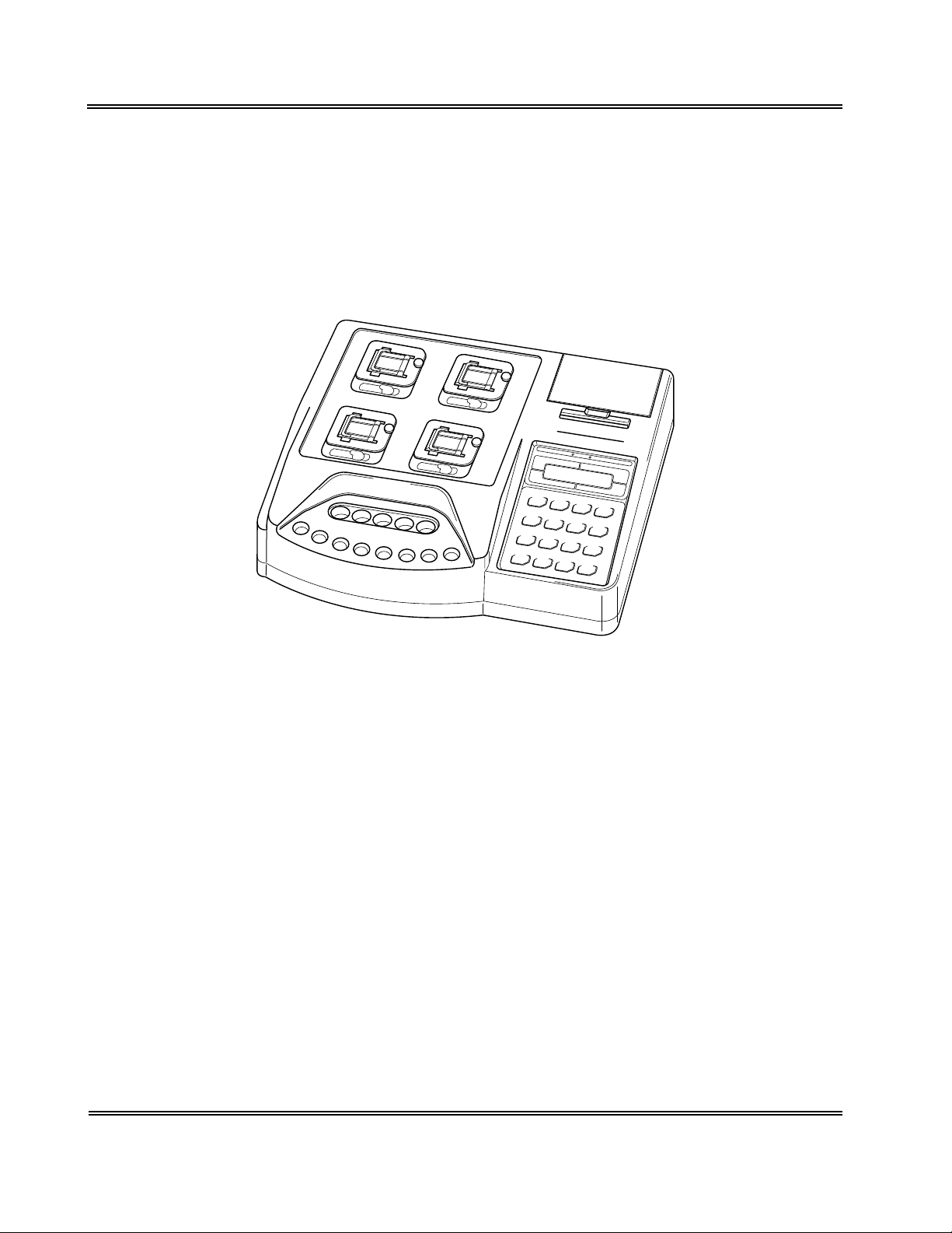
2 . INSTRUMENT OVERVIEW
The CA-50 is an automated blood coagulation analyzer that can quickly analyze samples with a
high degree of accuracy. The CA-50 can analyze samples using a Coagulation Method; and the
analyzed data can be displayed on its LCD screen and printed by the built-in printer. The CA-50
also has some supplemental functions including quality control.
Figure 1-1: Overview of CA-50
1-2 Sysmex CA-50 Operator’s Manual -- Revised December 2000
Page 18
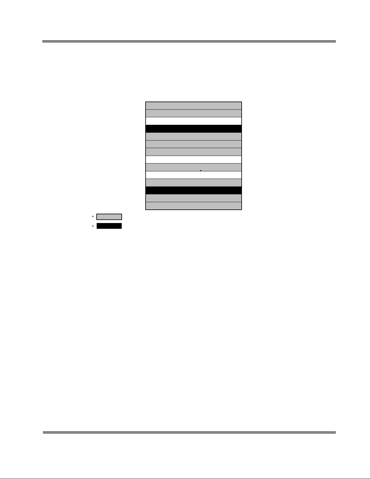
3 . OUTLINE OF OPERATION
g
The CA-50 performs an analysis by the following procedure.
Table 1-1: CA-50 Analysis Procedure
Check before turning ON power
Power ON
Self-check
Ready
Preparation for analysis
Work List
Press [START] key
Execution of sample incubation
Addition of reagents
Execution of analysis
Discard used reaction tubes
Ready
Power OFF
Operation after analysis completion
INTRODUCTION
Ready
:
Indicates actions performed by the operator.
:
Indicates that the instrument is in the ready status. At this time,
the detector LED of each channel will light up in green indicating
that you can perform operations such as analysis and settin
s.
Sysmex CA-50 Operator’s Manual -- Revised December 2000 1-3
Page 19
INTRODUCTION
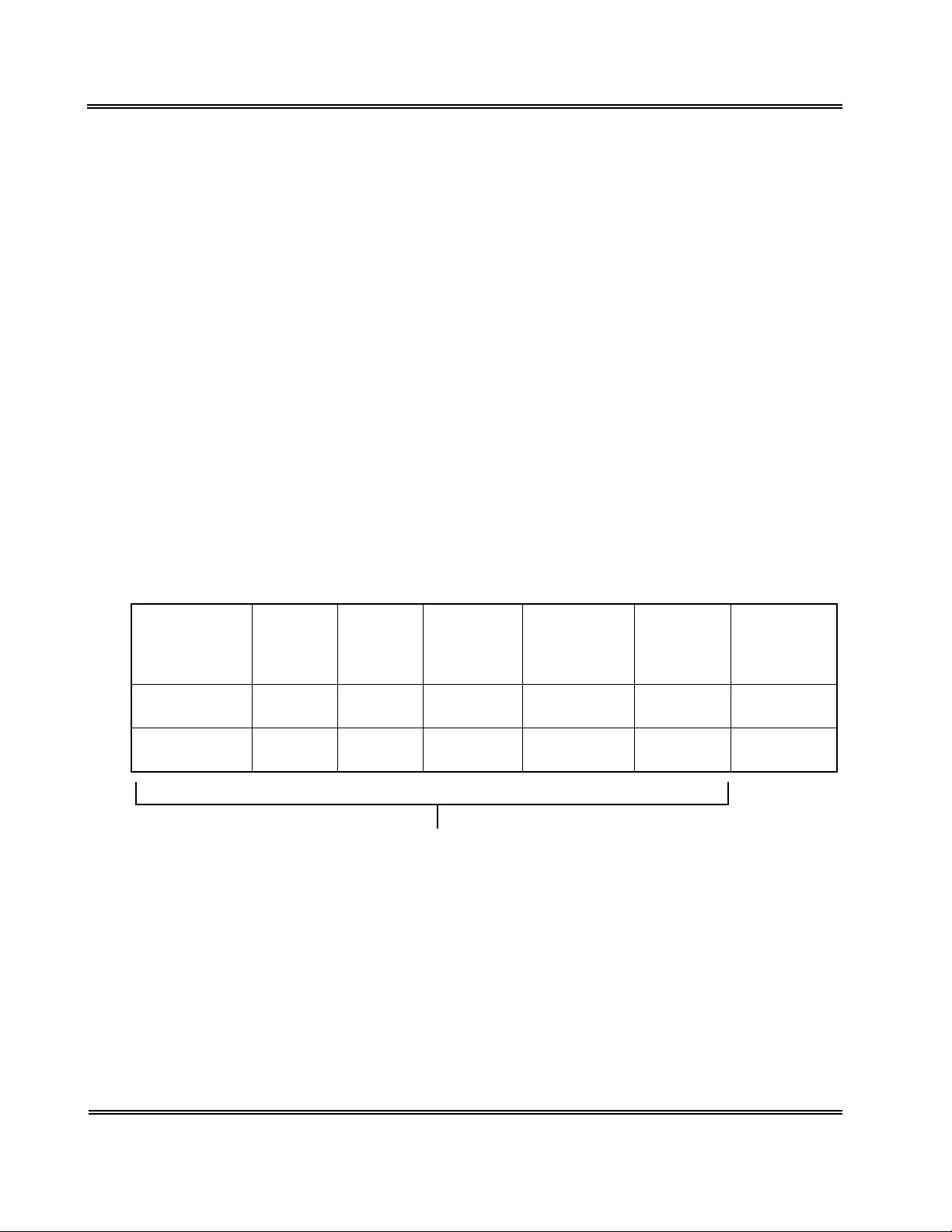
4 . ANALYSIS PARAMETERS AND CALCULATION PARAMETERS
The CA-50 can analyze and calculate the parameters shown below. Additional analysis and
calculation parameters can be registered as well.
The following list shows the analysis and calculation parameters that can be analyzed by the CA-
50.
Table 1-2: CA-50 Analysis Parameters and Calculation Parameters
Method Analysis parameter Calculation parameter
Coagulation
Method
Prothrombin Time (PT)
Activated Partial Thromboplastin Time
(APTT)
Fibrinogen (Fbg)
Thrombotest (TTO)
Normotest (NT)
Thrombin Time (TT)
Extrinsic Factor Deficiency Assay
(II, V, VII, X)
Intrinsic Factor Deficiency Assay
(VIII, IX, XI, XII)
Prothrombin Activity Percent
Prothrombin Ratio
INR
Derived Fbg
Fibrinogen Concentration
Thrombotest Activity Percent
Normotest Activity Percent
Factor II Activity Percent
Factor V Activity Percent
Factor VII Activity Percent
Factor VIII Activity Percent
Factor IX Activity Percent
Factor X Activity Percent
Factor XI Activity Percent
Factor XII Activity Percent
CAUTION
• If you analyze with a wrong reagent, correct analysis results will not be
obtained.
NOTE: • You can set up to 3 types of calculation parameters each for an analysis
parameter.
1-4 Sysmex CA-50 Operator’s Manual -- Revised December 2000
Page 20

INTRODUCTION
CAUTION
Interpretation of APTT Abnormal Early Reaction.
• APTT results less than or equal to 20.0 seconds, APTT results with NC
(No Coagulation), SC (Slight Coagulation) or CCE (Coag. Curve Error)
error messages, or abnormally short APTT results may be caused by an
abnormal early reaction.
APTT results with an abnormal early reaction can be identified in the
analysis data.
• If an APTT result less than or equal to 20.0 seconds is obtained, the
following steps should be taken:
1. Verify sample and reagent integrity along with maintenance procedures.
2. Print out the Analysis data.
See Chapter 4, Section 4: OUTPUTTING ANALYSIS RESULT and
Chapter 10, Section 4.2: Built-In Printer Settings.
Note that the stored analysis results will be deleted, when you start a
next analysis on the same channel or you turn OFF the power or so
on.
3. Observe time in the “2%” position.
4. If that time is equal to or less than 15 seconds, then an abnormal early
reaction may have occurred.
5. Re-analyze the sample.
6. If result is the same, it should not be reported.
7. Review the previous patient history to determine acceptability of
patient results. Results of the other parameters considered, then make
overall evaluation.
8. Follow your laboratory's alternate protocol.
• An error code may or may not be associated with this result.
• An abnormal early reaction rarely occurs.
• The CA-50 should be set up so that any APTT results of less than or
equal to 20.0 seconds will have a message of <20.1 seconds on the printout.
• To set up this function see Chapter 10, Section 3.4: Report Limit Settings
and enter 20.1 for the APTT lower limit.
• Remember to change the Built-in Printer Settings back to “List” after review
of the analysis data.
Sysmex CA-50 Operator’s Manual -- Revised December 2000 1-5
Page 21

INTRODUCTION
5 . LCD SCREEN AND INPUT KEYS
5. 1 LCD Screen
The instrument’s status, analysis results, and all other information are displayed on the CA-50’s
LCD screen. The screen is capable of displaying 16 characters by 2 lines maximum.
Display position of the each analysis channel on the screen
CH3 CH4
CH1 CH2
Figure 1-2: Display position of the each analysis channel on the screen
On the Analysis screen, the LCD screen is split into four parts to show the data of respective
channels from 1 to 4.
Analysis parameters are abbreviated into two characters as shown below:
• PT: PT • F5: Factor V
• AP: APTT • F7: Factor VII
• Fg: Fbg • F8: Factor VIII
• TO: TTO • F9: Factor IX
• NT: NT • 10: Factor X
• TT: TT • 11: Factor XI
• F2: Factor II • 12: Factor XII
Settings Screen
ID No. Entry
Select CH(1-4)?
1
Figure 1-3: Example of Settings Screen
On the Settings screen, parameters to be set or selected are displayed on the upper and lower
lines.
1-6 Sysmex CA-50 Operator’s Manual -- Revised December 2000
Page 22
INTRODUCTION
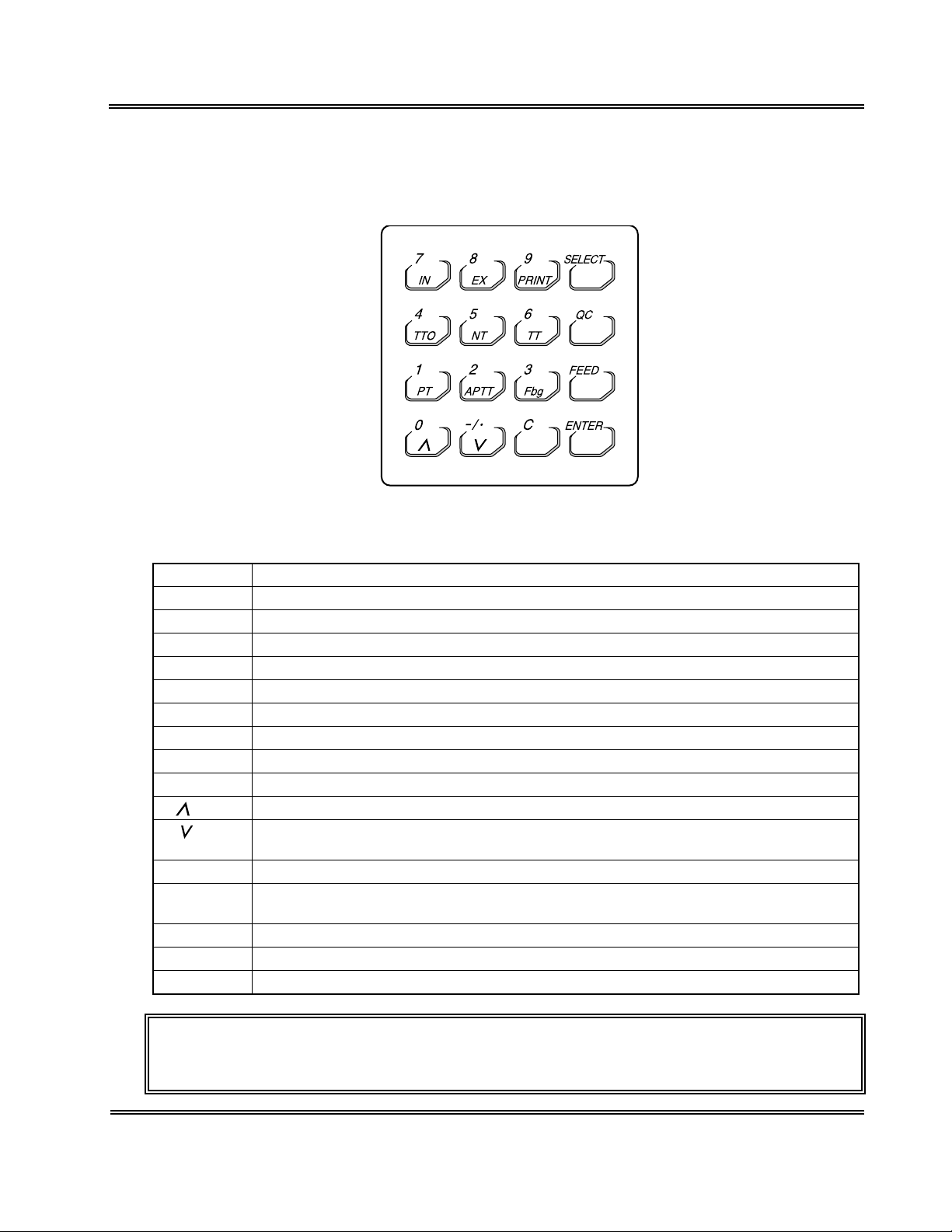
5. 2 Input Keys
By using the input keys, you can perform each setting such as entering numerals and selecting
various parameters.
Figure 1-4: Input Keys
Table 1-3: Operation of Input Keys
Key Operation
1/PT Press to input the number "1" or select "PT".
2/APTT Press to input the number "2" or select "APTT".
3/Fbg Press to input the number "3" or select "Fbg".
4/TTO Press to input the number "4" or select "TTO".
5/NT Press to input the number "5" or select "NT".
6/TT Press to input the number "6" or select "TT".
7/IN Press to input the number "7" or select "intrinsic factor".
8/EX Press to input the number "8" or select "extrinsic factor".
9/PRINT Press to input the number "9" or print a menu.
0/ Press to input the number "0", scroll a menu up, or switch to the previous data.
-/./ Press to input a hyphen or a decimal point, scroll a menu down, or switch to the next
data.
C Press to clear inputted data or stop an error beep.
SELECT Press to switch between Menu and Ready, cancel updated data (when confirmed), or
return to the previous screen.
QC Press to input "QC" (when inputting an ID number).
FEED Press to feed paper.
ENTER Press to set inputted data or execute updated data (when confirmed).
CAUTION: • When a key has two or more functions, the function will be changed over
depending on the situation when the key is pressed.
Sysmex CA-50 Operator’s Manual -- Revised December 2000 1-7
Page 23
INTRODUCTION
6 . PASSWORDS
Important programs are protected by a password so that the programs can be executed under the
control of a supervisor.
When a menu that is protected by a password is to be executed, a Password Entry window will
appear. To execute the menu, enter the preset password and press the [Enter] key.
For details on how to set the password, see Chapter 10, Section 5.4: Password Settings.
7 . ALARMS
The CA-50 makes three types of alarm sounds.
1. Key Entry
A short beep will sound each time an input key is pressed.
2. Reagent addition timing
Two short beeps followed by a long beep will sound to let you know the timing of adding
reagents.
The time allowed for reagent addition is preset at 10 seconds as default; 5 seconds before
and after the time of addition. If you wish to change the allowed time, see Chapter 10,
Section 3.2: Test Protocol Settings.
Table 1-4: Reagent Addition Timing Alarm
Reagent
addition allowed
time (start)
Two short
beeps
5 seconds
before
No sound A short
beep
• • •
A short beep A long beep A short beep A long beep
One beep
per second
Reagent
addition
For 0.5
seconds
Allowed time for reagent addition
3. Error
A long beep will sound when an error occurs on the instrument.
The beep will continue to sound until the [C] key is pressed.
• • •
One beep
per second
Reagent
addition
allowed time
(end)
An error beep
1-8 Sysmex CA-50 Operator’s Manual -- Revised December 2000
Page 24
8 . DETECTOR LED
The detector LED of each channel indicates the status as shown in the table below.
Table 1-5: Operation of Detector LED
INTRODUCTION
During
warming-up
Turns off Lights up in
Ready During
green
Reagent
incubation
Blinks in red Blinks in green Lights up in red Lights up in
addition timing
During photo
detection
green
9 . PACKAGING
The CA-50 is thoroughly checked before it is shipped from the factory, and is carefully
packaged to withstand shocks during shipment.
After the CA-50 has been delivered, check the packaging. Make sure that the instrument is free
of exterior damage.
Your Sysmex service representative will unpack and install the instrument after delivery and will
also set the initial settings.
Ready
Sysmex CA-50 Operator’s Manual -- Revised December 2000 1-9
Page 25
INTRODUCTION
10. INSTALLATION ENVIRONMENT
10.1 Installation and Relocation
The CA-50 is installed by your Sysmex Service representative. In case relocation becomes
necessary after installation, see Appendix A: INSTALLATION to install the instrument
correctly.
WARNING
CAUTION
• When relocating the CA-50, be sure to wear rubber gloves. After the
relocation, wash your hands with disinfectant solution.
If your hands are contaminated with blood, infection by bacteria or the like
can occur.
• When relocating the CA-50, hold the instrument securely. If the instrument
falls, you can get injured or the instrument can be damaged.
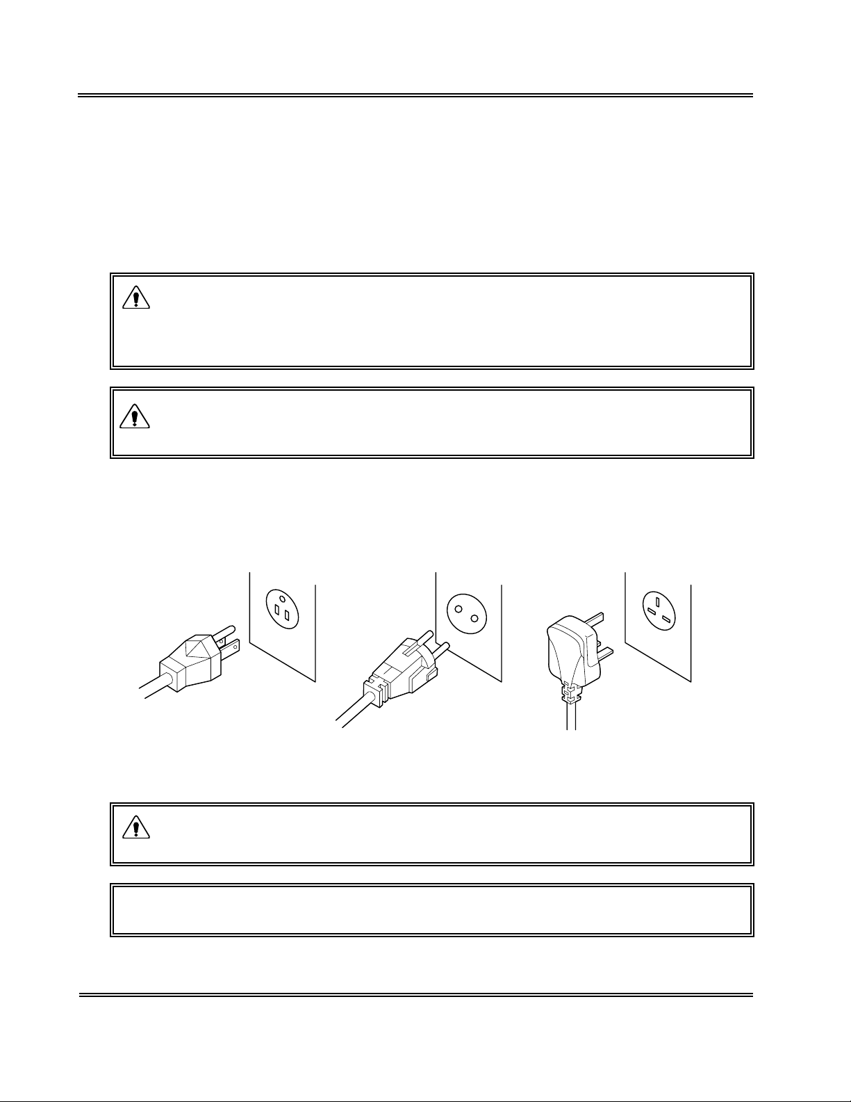
10.2 Grounding
The instrument power supply cord uses a 3-prong plug. When the power supply socket is 3prong (with grounded), simply plug it to the socket.
117 VAC Spec. 220 VAC Spec. 240 VAC Spec.
Figure 1-5: Plugs
WARNING
NOTE: • The number of power supply sockets required is 1.
• Make sure to ground the instrument. Inadequate grounding could cause
electrical shocks.
1-10 Sysmex CA-50 Operator’s Manual -- Revised December 2000
Page 26
INTRODUCTION
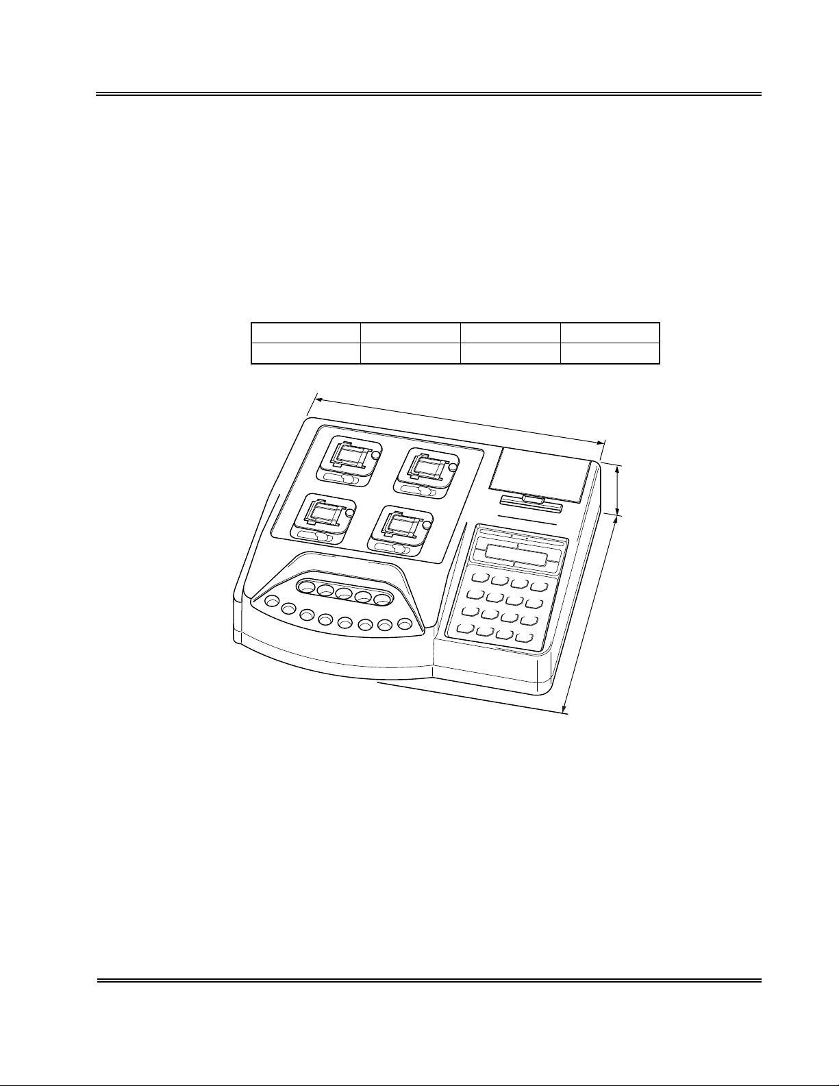
10.3 Installation Space
To ensure that the instrument fulfills its function, it is important to install it in an appropriate
place:
• Select a place that is close to the power supply.
• Secure a place spacious enough for maintenance and service. Giving consideration to heat
radiation by the instrument, provide at least 10 cm distance from the wall to the rear panel.
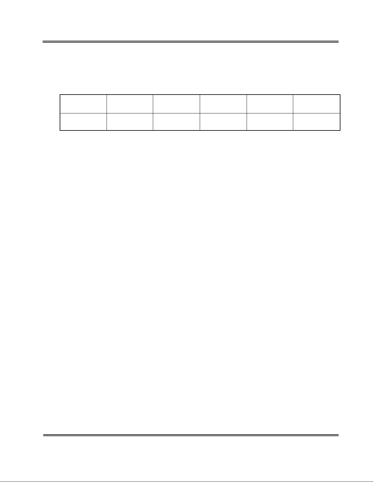
The instrument dimensions are shown below. The power supply cord is 1.8 m long.
Table 1-6: Instrument Dimensions
Width (mm) Depth (mm) Height (mm) Weight (kg)
327 302 113 4.5
327 mm
113 mm
302 mm
Figure 1-6: Instrument Dimensions
10.4 Installation Environment
• Use the instrument at an ambient temperature of 15°C - 35°C (optimum: 23°C).
• Use it at a relative humidity range of 30% - 85%.
• Avoid a place that can become extremely hot or cold.
• Avoid a place that can be exposed to direct sunlight.
• Choose a well-ventilated place.
• Avoid a place close to a wireless telegraph or communication facility where high frequency
waves can be generated or radio interference can occur.
• Do not use in dusty areas.
Sysmex CA-50 Operator’s Manual -- Revised December 2000 1-11
Page 27

INTRODUCTION
11 . INSTRUMENT SPECIFICATIONS
Analysis parameters/Calculation parameters
See Section 4: ANALYSIS PARAMETERS AND CALCULATION PARAMETERS in this
chapter.
Simultaneous Random Analysis of 4 Parameters
Random analysis is possible.
Required Sample
Prothrombin Time (PT): 50 µL
Activated Partial Thromboplastin Time (APTT): 50 µL
Fibrinogen (Fbg): 10 µL
Thrombotest (TTO): 20 µL
Normotest (NT): 10 µL
Thrombin Time (TT): 100 µL
Extrinsic Factor Deficiency Assay (II, V, VII, X): 5 µL
Intrinsic Factor Deficiency Assay (VIII, IX, XI, XII): 5 µL
Analysis Principles
Coagulation Method
1. Coagulation Reaction Detection Method (Scattered Light Detection Method)
Irradiates red light (660 nm) onto a mixture of blood plasma and reagent and detects the
change in turbidity (when the fibrin clots are formed) as the change in scattered light. And
measures the coagulation time.
2. Coagulation Point Detection Method (Percentage Detection Method)
Calculates the coagulation time as the time required to achieve the amount of scattered light
that is set for the coagulation detection point, using the amount of scattered light that is
present just after the start of detection as 0%, and the amount of scattered light that is
present at the completion of coagulation as 100%.
Range of Analysis
Fibrinogen Concentration
Can analyze from 50 mg/dL to 450 mg/dL.
Detection Time
Detects within the maximum detection time, and measures the result.
Typical maximum detection time: 100 seconds for PT and Fbg; 190 seconds for others.
Maximum detection time: 600 seconds for each parameter
1-12 Sysmex CA-50 Operator’s Manual -- Revised December 2000
Page 28

INTRODUCTION
Reproducibility
Prothrombin Time (PT): C.V. 2% or less
Activated Partial Thromboplastin Time (APTT): C.V. 2% or less
Fibrinogen (Fbg): C.V. 4% or less
Thrombotest (TTO): C.V. 4% or less
Normotest (NT): C.V. 4% or less
Thrombin Time (TT): C.V. 10% or less
Extrinsic Factor Deficiency Assay (II, V, VII, X): C.V. 5% or less
Intrinsic Factor Deficiency Assay (VIII, IX, XI, XII): C.V. 5% or less
* The data above are variation coefficients for coagulation times (in seconds) or for the amount
of change in activity% taken from 10 analyses of Dade Behring Ci-Trol Level 1 (control
plasma), with the reagents below used.
Thromboplastin•C plus
Dade Behring Actin Activated Cephaloplastin Reagent
20 mM Calcium Chloride Solution
Dade Behring Fibrinogen Determination Reagents
Owren's Veronal Buffer
CA Series Complex Factor TTO
CA Series Complex Factor HPT
Dade Behring Factor-deficient Plasma
Display
Displays characters on a liquid crystal display (LCD).
Printing
Permits graphic printing through a built-in printer. (Printer paper specification: F1-1, width: 58
mm)
External Input/Output
Equipped with an RS-232C serial port (bit serial voltage signal).
Detector
Detector: 4 wells (Scattered light detector)
Incubator
Incubator: 5 wells
Reaction Tube Holder
Reaction tube holder: 8 wells
Temperature Control
Detector: 37°C±0.5°C
Incubator: 37°C±1°C
Applies when room temperature is within 15°C - 35°C.
Time to Reach Temperature Setting
Reaches preset temperature within 30 minutes after power is turned ON (when the room
temperature is within the specified range).
Sysmex CA-50 Operator’s Manual -- Revised December 2000 1-13
Page 29

INTRODUCTION
Quality Control
control (L-J control): 50 points × 3 files, 14 parameters
X
Standard Curve
6 points, 14 parameters
Power
Rated voltage: 117 VAC±10%, 230 VAC±15%
Frequency: 50 Hz or 60 Hz
Power consumption: 90 VA or less
Temperature Compensation Required: Approx. 307 BTU/h (77 kcal/h)
Environmental Requirements
15°C - 35°C
Dimensions/Weight
Main Unit: 327 (W) × 302 (D) × 113 (H) mm; approx. 4.5 kg
1-14 Sysmex CA-50 Operator’s Manual -- Revised December 2000
Page 30

INTRODUCTION
CAUTION
Interpretation of APTT Abnormal Early Reaction.
• APTT results less than or equal to 20.0 seconds, APTT results with NC
(No Coagulation), SC (Slight Coagulation) or CCE (Coag. Curve Error)
error messages, or abnormally short APTT results may be caused by an
abnormal early reaction.
APTT results with an abnormal early reaction can be identified in the
analysis data.
• If an APTT result less than or equal to 20.0 seconds is obtained, the
following steps should be taken:
1. Verify sample and reagent integrity along with maintenance procedures.
2. Print out the Analysis data.
See Chapter 4, Section 4: OUTPUTTING ANALYSIS RESULT and
Chapter 10, Section 4.2: Built-In Printer Settings.
Note that the stored analysis results will be deleted, when you start a
next analysis on the same channel or you turn OFF the power or so
on.
3. Observe time in the “2%” position.
4. If that time is equal to or less than 15 seconds, then an abnormal early
reaction may have occurred.
5. Re-analyze the sample.
6. If result is the same, it should not be reported.
7. Review the previous patient history to determine acceptability of
patient results. Results of the other parameters considered, then make
overall evaluation.
8. Follow your laboratory's alternate protocol.
• An error code may or may not be associated with this result.
• An abnormal early reaction rarely occurs.
• The CA-50 should be set up so that any APTT results of less than or
equal to 20.0 seconds will have a message of <20.1 seconds on the printout.
• To set up this function see Chapter 10, Section 3.4: Report Limit Settings
and enter 20.1 for the APTT lower limit.
• Remember to change the Built-in Printer Settings back to “List” after review
of the analysis data.
Sysmex CA-50 Operator’s Manual -- Revised December 2000 1-15
Page 31
INTRODUCTION
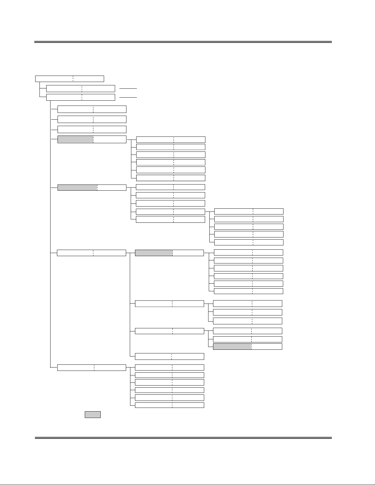
12 . MENU TREE
Ready
Analysis Start
MAIN MENU
Chapter 2, 3
Chapter 3, 3.1
Chapter 1, B
1. Select Test
2. ID No. Entry
3. Display Data
4. QC
5. Standard Curve
6. Settings
Chapter 3, 2.1
Chapter 3, 2.2
Chapter 4, 3
Chapter 6, 2
Chapter 7, 3
Chapter 10, 2
Press the [Start] switch.
Press the [SELECT] key.
1. Select Test
2. Select File
3. Print
4. Delete a Point
5. Settings
6. Clear a File
1. Select Test
2. Input
3. Print
4. Settings
5. Clear
1. Meas. Settings
Chapter 6, 3.1
Chapter 6, 3.2
Chapter 6, 4
Chapter 6, 5.1
Chapter 6, 6
Chapter 6, 5.2
Chapter 7, 4.1
Chapter 7, 4.2
Chapter 7, 5
Chapter 7, 6.1
Chapter 7, 7
Chapter 10, 3.1
1. Activity/Conc.
2. Ratio
3. INR
4. Dfbg
5. Print Settings
1. Test Protocol
2. Mark Limits
3. Report Limits
4. Diff. Check
5. Measure Mode
6. Conversion
Chapter 7, 6.2
Chapter 7, 6.3
Chapter 7, 6.4
Chapter 7, 6.5
Chapter 7, 6.6
Chapter 10, 3.2
Chapter 10, 3.3
Chapter 10, 3.4
Chapter 10, 3.5
Chapter 10, 3.6
Chapter 10, 3.7
Chapter 10, 4.2
Chapter 10, 4.3
Chapter 10, 4.4
Chapter 10, 5.2
Chapter 10, 5.3
Chapter 10, 5.4
7. Test Programs
2. I/O Settings
3. System Setting
4. Print Settings
Chapter 8, 4.1
: The password has to be entered if it is set.
1. Temperature
2. Sensor
3. Key
4. Printer
5. Host Computer
6. LCD
Chapter 10, 4.1
Chapter 10, 5.1
Chapter 10, 6
Chapter 8, 4.2
Chapter 8, 4.3
Chapter 8, 4.4
Chapter 8, 4.5
Chapter 8, 4.6
Chapter 8, 4.7
1. Printer
2. Host Computer
3. Print Settings
1. Date
2. Time
3. Password
1-16 Sysmex CA-50 Operator’s Manual -- Revised December 2000
Page 32

INTRODUCTION
13 . MAIN MENU
The Main Menu screen shows the menu for selecting and utilizing the functions provided with
the CA-50.
When you press the [SELECT] key on the Ready screen, the Main Menu screen will appear. For
details on the Ready screen, see Chapter 2, Section 3: TURNING ON THE POWER.
You can scroll the menu up and down by using the [ ] and [ ] keys.
MAIN MENU
1.Select Test
2.ID No. Entry
3.Display Data
4.QC
5.Standard Curve
6.Settings
7.Test Programs
Figure 1-7: Main Menu Screen
Pressing the following key will select each menu function.
[1] key: Moves the screen to the selection of analysis parameters (Select Test).
[2] key: Moves the screen to the entry of ID numbers (ID No. Entry).
[3] key: Moves the screen to the display of detailed analysis results (Display Data).
[4] key: Displays the quality control menu (QC).
[5] key: Displays the standard curve menu (Standard Curve).
[6] key: Displays the setting menu (Settings).
[7] key: Displays the test program menu (Test Programs).
[PRINT] key: Prints out the main menu.
[SELECT] key: Returns the screen to the Ready screen.
Sysmex CA-50 Operator’s Manual -- Revised December 2000 1-17
Page 33

CHAPTER 2 ANALYSIS PREPARATION
1. INTRODUCTION ................................................................................2-1
2. BEFORE TURNING ON THE POWER ......................................................2-2
3. TURNING ON THE POWER ..................................................................2-2
4. REAGENT PREPARATION....................................................................2-4
4.1 Preparing the Reagents ....................................................................2-4
4.2 Setting the Reaction Tubes and Reagents................................................2-5
5. CHECKING THE STANDARD CURVES ...................................................2-6
6. QUALITY CONTROL ...........................................................................2-7
7. SAMPLE PREPARATION......................................................................2-8
Sysmex CA-50 Operator’s Manual -- Revised July 1999
Page 34

ANALYSIS PREPARATION
1. INTRODUCTION
Before beginning analysis, it is necessary to prepare the instrument, reagents, and samples.
Prepare for analysis by following the steps described below.
Table 2-1: Analysis Flow Chart
Check visually before
Turning ON the Power
Turn ON the Power
Prepare Reagents
Set Reaction Tubes and Reagents
Check Standard Curves
Run Quality Control
Prepare Samples
Make Work List
Analyze Samples
Start an Analysis
Add Reagents
All are explained in this chapter.
Refer to
Chapter 3: SAMPLE
ANALYSIS.
Shutdown
Sysmex CA-50 Operator’s Manual -- Revised July 1999 2-1
Page 35

ANALYSIS PREPARATION
y
2 . BEFORE TURNING ON THE POWER
Before turning ON the power to the instrument, check the following items:
1 . CA-50 Instrument Visual Check
Make sure that the power cord is securely plugged into the AC outlet.
Also, check whether the used reaction tube is not left in the detector.
2 . Printer Paper
If a printer is provided, make sure that it contains the amount of paper necessary for the
number of samples to be processed that day. Prepare extra paper when the remains of
paper run short.
3 . TURNING ON THE POWER
When you turn ON the power switch that is located on the right side, the instrument will
automatically perform a self-check.
(1) Turn ON the power switch.
A self-check will automatically be performed. When the self-check is completed without
finding any error, "OK" will be displayed on the screen and the built-in printer will output
a test print.
If an error occurs during the self-check, see Chapter 8: TROUBLESHOOTING.
Sysmex CA-50
Self Test OK
Figure 2-1: Self-Check Screen
15/06/1999 09:00
This is CA-50.
Blood Coagulation Analyzer
Produced by Sysmex
Figure 2-2: Example of Test Print
When the self-check is completed, the detector and the incubator will be warmed up.
During the warming-up, "warm" will be displayed on each channel of the screen.
NOTE: • The analysis parameter that was used in the previous analysis is
displa
ed on each channel.
2-2 Sysmex CA-50 Operator’s Manual -- Revised July 1999
Sysmex CA-50 Operator’s Manual -- Revised August 1999
Page 36

ANALYSIS PREPARATION
Fg warm AP warm
PT warm AP warm
Figure 2-3: Warming-Up Screen
The "warm" will disappear and the detector LED will light up in green one by one as soon as
each channel completes the warming-up. It takes about 5 minutes to 30 minutes until the "warm"
disappears.
This status is called "Ready." You can perform various operations such as analysis and settings
on the channel that has entered the "Ready" status.
Fg AP
PT AP
Figure 2-4: Ready Screen
If you press the [SELECT] key on this screen, the Main Menu screen will appear. For details on
the Main Menu screen, see Chapter 1, Section 13: MAIN MENU.
Sysmex CA-50 Operator’s Manual -- Revised July 1999 2-3
Page 37
ANALYSIS PREPARATION
g
(
)
g
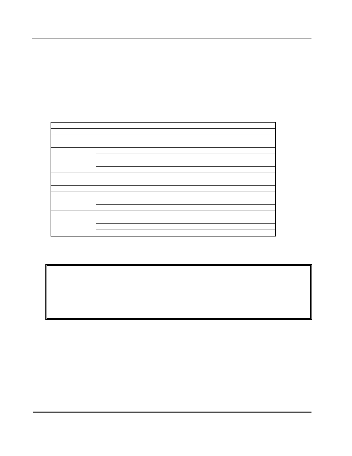
4. REAGENT PREPARATION
4.1 Preparing the Reagents
Prepare the required volume of coagulation reagents and Owren’s Veronal buffer for the
anticipated work load.
Table 2-2: Reagent Preparation
Parameter Reagent Consumption/Test
PT PT Reagent 100 µL
APTT APTT Reagent 50 µL
Calcium Chloride Solution 50 µL
Fbg Thrombin Reagent 50 µL
Owren's Veronal Buffer 90 µL
TTO Thrombotest Reagent 125 µL
Owren's Veronal Buffer 30 µL
NT Normotest Reagent 125 µL
Owren's Veronal Buffer 40 µL
TT Thrombin Time Reagent 50 µL
Extrinsic Factor PT Reagent 100 µL
Deficient Factor-deficient Plasma 50 µL
Assay Owren's Veronal Buffer 45 µL
Intrinsic Factor APTT Reagent 50 µL
Deficient Calcium Chloride Solution 50 µL
Assay Factor-deficient Plasma 50 µL
Owren's Veronal Buffer 45 µL
When you prepare reagents, take into account the analysis parameters and the number of
samples to be analyzed.
CAUTION: • We recommend that you use the following pipettes and pipette chips to
add plasma and dispense/add rea
• Pipette: Eppendorf reference 4910
• Pipette chip: Eppendorf 300 µL chip
For details on the usa
e of the pipette and pipette chip, refer to the
instruction manuals attached to them.
ents.
50 - 200 µL
2-4 Sysmex CA-50 Operator’s Manual -- Revised July 1999
Page 38

ANALYSIS PREPARATION
4.2 Setting the Reaction Tubes and Reagents
Set reaction tubes and reagents into the instrument.
(1) Set reaction tubes into the reaction tube holder. Prepare a sufficient number of reaction
tubes beforehand.
Reaction tube
Reaction tube holder
Figure 2-5: Setting the Reaction Tubes
CAUTION: • Be sure to use the specified reaction tube (SU-40).
(2) Dispense the reagents to be used into the sample cups, and set them into the incubator.
Incubator
Sample cup
Figure 2-6: Setting the Reagents
Sysmex CA-50 Operator’s Manual -- Revised July 1999 2-5
Page 39

ANALYSIS PREPARATION
(
q
WARNING
CAUTION: • Do not set the reagent of 2 mL or more in the incubator. The reagent will not
• Cap the sample cups that are set in the incubator if they are not used. If
contaminants or dusts get in the reagent, or if the reagent evaporates,
correct analysis results will not be obtained.
• Let the incubator incubate the reagents more than 10 minutes. If the
incubation is insufficient, correct analysis results may not be obtained.
As the reagent may deteriorate, do not use the APTT reagent incubated
for 20 minutes or more and the other reagents incubated for 40 minutes or
more.
• Do not replenish reagents. Correct analysis results may not be obtained.
reach the desired temperature.
• Be sure to use the specified sample cup
e
uivalent).
Uniflex Conical 4 mL or the
5 . CHECKING THE STANDARD CURVES
Before performing an analysis, print out standard curves and make sure that they are correctly
set.
For the procedure to print out standard curves, see Chapter 7, Section 5: PRINTING OUT THE
STANDARD CURVE.
CAUTION: • If the standard curve is not set correctly, it is not possible to calculate the
calculation parameters such as the PT %.
If the settings are incorrect, set them correctly referring to Chapter 7: SETTING STANDARD
CURVES.
2-6 Sysmex CA-50 Operator’s Manual -- Revised July 1999
Page 40

ANALYSIS PREPARATION
6. QUALITY CONTROL
To maintain reliable analysis data, it is necessary to implement quality control. With the CA-50,
a quality control file number (QC1 - QC3) can be registered as a sample ID number, the control
material (control plasma) is analyzed, and the analysis data is stored in a quality control file. This
data and a quality control program are used to monitor changes in the instrument and reagent
system that take place over time (day-to-day or hour-to-hour).
For details on quality control, see Chapter 6: QUALITY CONTROL.
Implementing Quality Control
When performing a quality control analysis, dispense control material into a reaction tube.
The procedure for a quality control analysis is the same as that for a sample analysis. For details,
see Chapter 3: SAMPLE ANALYSIS.
(1) Register the analysis parameter in the channel used for the analysis.
(2) Press the [QC] key on the ID No. Entry screen, and input the ID number for quality
control (any number from 1 to 3).
(3) Dispense control material into a reaction tube and set it into the detector.
(4) Press the [Start] switch.
(5) Add a reagent at the indicated timing, and close the pipette guide.
The analysis will be performed, and the analysis data will be stored in a quality control
file.
(6) Print out a QC chart and check the status of analysis data.
Sysmex CA-50 Operator’s Manual -- Revised July 1999 2-7
Page 41

ANALYSIS PREPARATION
y
y
y
y
7. SAMPLE PREPARATION
Prepare sample tubes containing plasma.
NOTE: • When handling the sample, be sure to wear rubber gloves. After the
operation is completed, wash
Failure to do so can cause infection b
(1) Add 1 part of 3.8%, 3.2% or 3.13% sodium citrate solution as anticoagulant to 9 parts of
venous blood, and mix the contents thoroughly.
(2) Centrifuge the mixture at 3000 rpm for 15 minutes to separate plasma components from
blood-cell components.
(3) Put only the centrifuged plasma into another test tube.
our hands with disinfectant solution.
bacteria.
CAUTION
Precautions when handling plasma:
• Containers should be plastic or silicone-coated glass tube.
• As anticoagulant, use 3.8%, 3.2% or 3.13% sodium citrate solution.
When any other anticoagulant is used, sedimentation may occur and
correct analysis result may not be obtained.
• Mix blood and sodium citrate solution in an accurate ratio of 9 parts to 1
part, respectively.
When the mixing ratio varies, coagulation time varies, occasionally
leading to incorrect analysis result.
• Store samples in the refrigerator and analyze within 4 hours of
collecting.
After 4 hours, or if the
ma
not be obtained.
are stored improperly, correct analysis results
2-8 Sysmex CA-50 Operator’s Manual -- Revised July 1999
Sysmex CA-50 Operator’s Manual -- Revised December 1999
Page 42

CHAPTER 3 SAMPLE ANALYSIS
1. INTRODUCTION................................................................................ 3-1
2. WORK LIST...................................................................................... 3-2
2.1 Selecting the Analysis Parameter.........................................................3-2
2.2 Registering the Sample ID Number......................................................3-4
3. SAMPLE ANALYSIS ...........................................................................3-6
3.1 Start of Analysis ........................................................................... 3-7
3.2 Adding the Reagents.......................................................................3-8
3.3 Registering and Analyzing the Next Sample...........................................3-11
4. SHUTDOWN ....................................................................................3-12
Sysmex CA-50 Operator’s Manual -- Revised July 1999
Page 43

SAMPLE ANALYSIS
1. INTRODUCTION
This chapter will explain the operating procedures for the order information registration and from
the start of analysis to shutdown.
Table 3-1: Analysis Flow Chart
Check visually before
Turning ON the Power
Turn ON the Power
Prepare Reagents
Set Reaction Tubes and Reagnets
Check Standard Curves
Run Quality Control
Prepare Samples
Make Work List
Analyze Samples
Start an analysis
Add Reagents
Shutdown
Refer to
PREPARATION.
All are explained in this chapter.
Chapter 2:
ANALYSIS
Sysmex CA-50 Operator’s Manual -- Revised July 1999 3-1
Page 44

SAMPLE ANALYSIS
p
2 . WORK LIST
Register the analysis parameter and the sample ID number of each channel.
2.1 Selecting the Analysis Parameter
NOTE: • When the power is turned ON, the analysis parameter used in the
revious analysis is displayed on each channel.
(1) Press the [SELECT] key to enter the Main Menu screen.
MAIN MENU
1.Select Test
2.ID No. Entry
3.Display Data
4.QC
5.Standard Curve
6.Settings
7.Test Programs
Figure 3-1: Main Menu Screen
(2) Press the [1] key on the Main Menu screen.
The Channel Selection screen will appear.
Select Test
Select CH(1-4)?1
Figure 3-2: Channel Selection Screen
If you press the [SELECT] key, the display will return to the Main Menu screen (Figure 3-
1).
3-2 Sysmex CA-50 Operator’s Manual -- Revised July 1999
Page 45

SAMPLE ANALYSIS
(3) Input the channel number (any number from 1 to 4) on which you wish to select the
analysis parameter, and press the [ENTER] key. However, when the replication measure
mode is set (See Chapter 10, Section 3.6: Measure Mode & Sample Incubation Ready
Check Settings.), select the channel number either 1 or 3.
The Analysis Parameter Selection screen will appear. (The parameter set in the previous
analysis is displayed.)
Select Test CH2
Test(PT-EX)? PT
Figure 3-3: Analysis Parameter Selection Screen
If you press the [SELECT] key, the display will return to the Channel Selection screen
(Figure 3-2).
(4) Press the key for the desired parameter, and press the [ENTER] key.
In the case of an intrinsic factor assay (8, 9, 11, or 12), press the [IN] key.
In the case of an extrinsic factor assay (2, 5, 7, or 10), press the [EX] key.
When you press the [IN] or [EX] key, the Factor Number Entry screen will appear.
When you press any of the other keys, the display will return to the Channel Selection
screen (Figure 3-2). Set the analysis parameter of the other channels in the same manner.
Select Test CH2
IN(8,9,11,12)? 8
Figure 3-4: Factor Number Entry Screen
If you press the [SELECT] key, the display will return to the Channel Selection screen
(Figure 3-2).
(5) In the case of an intrinsic factor assay, input any of 8, 9, 11, and 12.
In the case of an extrinsic factor assay, input any of 2, 5, 7, and 10.
Then press the [ENTER] key.
The display will return to the Channel Selection screen (Figure 3-2). Set the analysis
parameter of the other channels in the same manner.
Sysmex CA-50 Operator’s Manual -- Revised July 1999 3-3
Page 46

SAMPLE ANALYSIS
2.2 Registering the Sample ID Number
(1) Press the [SELECT] key to enter the Main Menu screen.
MAIN MENU
1.Select Test
2.ID No. Entry
3.Display Data
4.QC
5.Standard Curve
6.Settings
7.Test Programs
Figure 3-5: Main Menu Screen
(2) Press the [2] key on the Main Menu screen.
The Channel Selection screen will appear.
ID No. Entry
Select CH(1-4)?
Figure 3-6: Channel Selection Screen
If you press the [SELECT] key, the display will return to the Main Menu screen (Figure 3-
5).
(3) Input the channel number (any number from 1 to 4) on which you wish to register the
sample ID number, and press the [ENTER] key.
The ID No. Entry screen will appear.
ID No. Entry CH2
123-456
Figure 3-7: ID No. Entry Screen
If you press the [SELECT] key, the display will return to the Channel Selection screen
(Figure 3-6).
3-4 Sysmex CA-50 Operator’s Manual -- Revised July 1999
Page 47

SAMPLE ANALYSIS
q
g
p
p
p
yp
g
p
p
p
y
(4) Input the ID number, and press the [ENTER] key.
The display will return to the Channel Selection screen (Figure 3-6). The sample ID
number can be registered with up to 15 digits consisting of numerals and hyphens (-). The
hyphens, however, cannot be used consecutively or as the first or last digits of the sample
ID number.
When a quality control analysis is performed, press the [QC] key and input any number
from 1 to 3.
NOTE: • If you do not input a sample ID number after the power is turned ON, the
number will be se
re
ardless of the channel or the analysis parameter.
• If a sam
from the ID number in
arameter.
• When a h
automatic increment will be the di
For exam
will be "990601-00."
• If "0" is in
And, if "0", "QC1", "QC2", or "QC3" is in
onl
le ID number is input, the number will be sequentially incremented
hen is used in the sample ID number, the subject of the
le, when the sample ID number is "990601-99", the next number
ut to the ID number, an external output will not be carried out.
one time at the input without automatic incrementing.
uentially incremented from "1" in each analysis
ut last regardless of the channel or the analysis
its after the hyphen.
ut, the ID number will become
Sysmex CA-50 Operator’s Manual -- Revised July 1999 3-5
Page 48

SAMPLE ANALYSIS
p
y
g
y
g
g
m
g
g
y
y
pip
y
p
g
y
3. SAMPLE ANALYSIS
When the detector LED is lit in green, you can perform an analysis on this channel. It is possible
to perform analyses on multiple channels simultaneously.
The CA-50 has a function to turn off the detector LED indicating the Ready status and prevent an
analysis from being started when the timings of reagent addition are expected to overlap one
another.
WARNING
CAUTION
• Be sure to wear rubber gloves during the analysis. After the operation is
com
leted, wash your hands with disinfectant solution. Failure to do so can
cause infection b
• Handle reaction tubes containin
an
infection by bacteria.
When discardin
medical and infectious wastes.
• The total volume of blood and rea
L. If the volume exceeds this range, sample may spill out of the reaction
tube when bein
• Be careful not to spill blood or reagents into the detector. This may damage
the instrument.
• Use the correct volume of blood and rea
correct anal
not be detected. For the specific volume required for each analysis, see
Chapter 9, Section 2.6: Analysis Flow
• Use a new
one even when
contaminated with the other sam
not be obtained.
• Be careful so that rea
Correct anal
bacteria.
sample with extreme care in order to avoid
used reaction tubes, take proper disposing steps as
ents must be in the range of 150 to 200
mixed, resulting in infection by bacteria.
ents. If the volume is improper,
sis results may not be obtained, or addition of reagents ma
.
ette chip each time. Replace the pipette chip with a new
ou add the same reagent consecutively. If sample is
le or reagent, correct analysis results will
ents or contaminants will not get in the reaction tube.
sis results will not be obtained.
3-6 Sysmex CA-50 Operator’s Manual -- Revised July 1999
Page 49

3.1 Start of Analysis
y
p
(1) Pipette plasma into a reaction tube and set it into the detector.
At this time, push it into the bottom of the detector firmly.
SAMPLE ANALYSIS
Reaction tube
Detector
Figure 3-8: Setting Plasma
(2) Press the [Start] switch.
Incubation of plasma will start. The reagent to be added and the countdown of the
remaining time before the reagent addition timing will be displayed on the screen. The
detector LED will blink in red.
PT Fg
AP PT 179
Figure 3-9: Display of Countdown
CAUTION: • When you press the [Start] switch by mistake, you can cancel the
anal
sis by pressing the [Start] switch again. However, the alarm sounds
in this case, and sto
s the alarm by pressing the [C] key.
Sysmex CA-50 Operator’s Manual -- Revised July 1999 3-7
Page 50

SAMPLE ANALYSIS
)
(
)
p
p
p
p
p
p
p
p
y
g
g
y
g
g
p
g
y
g
g
p
3.2 Adding the Reagents
When a reagent addition timing comes, an alarm will begin to sound and the detector LED will
blink in green. The detailed operations of the alarm and the detector LED are as shown below:
Table 3-2: Reagent Addition Timing Alarm
Reagent
addition allowed
time (start
Two short
beeps
5 seconds
before
No sound A short
bee
· · ·
A short beepA long bee
One bee
er second
Reagent
addition
For 0.5
seconds
· · ·
A short beepA long bee
One bee
er second
Reagent
addition
allowed time
end
An error bee
Allowed time for reagent addition
The time allowed for reagent addition is preset at 10 seconds as default; 5 seconds before and
after the time of addition. If you wish to change the allowed time, see Chapter 10, Section 3.2:
Test Protocol Settings.
Table 3-3: Operation of Detector LED
During warming-upRead
Turns off Lights up in
reen
Durin
incubation
Blinks in red Blinks in green Lights up in red Lights up in
Reagent addition
timin
During photo
detection
Read
reen
(1) When the alarm begins to sound, take the reagent to be added with a pipette.
CAUTION
• When two or more reagents are set in the incubator, be careful not to mix
u
them. If an incorrect reagent is used, correct analysis results will not be
obtained.
• Use the rea
insufficient, correct anal
Also, as the rea
incubated for 20 minutes or more and the other rea
ent incubated more than 10 minutes. If the incubation is
sis results may not be obtained.
ent may deteriorate, do not use the APTT reagent
ents incubated for 40
minutes or more.
• Do not re
lenish reagents. Correct analysis results may not be obtained.
3-8 Sysmex CA-50 Operator’s Manual -- Revised July 1999
Page 51

SAMPLE ANALYSIS
pip
p
)
p
pip
p
y
CAUTION: • We recommend that you use the following pipettes and pipette chips to
ette plasma and dispense/add reagents.
•Pi
ette: Eppendorf reference 4910 (50 - 200 mL
•Pipette chip:Eppendorf 300 mL chi
For details on the usage of the pipette and pipette chip, refer to the
instruction manuals attached to them.
• Use the
ette correctly calibrated.
(2) Add the reagent when a long beep sounds.
Add the reagent in a manner as to avoid bubbling the sample, while fixing the pipette chip
to the pipette guide and applying the tip of the pipette chip to the inside wall of
the reaction tube.
Mark indicating the area where
the pipette chip tip should be fixed
CAUTION
Pipette guide
When holding
the pipette by
the right hand
Area where the pipette
chip tip should be fixed
When holding
the pipette by
the left hand
Figure 3-10: Adding the Reagent
• When you use multiple channels simultaneously, be careful not to mix u
the detectors. If you add a reagent into an incorrect detector, correct
anal
sis results will not be obtained.
Sysmex CA-50 Operator’s Manual -- Revised July 1999 3-9
Page 52

SAMPLE ANALYSIS
pip
g
p
pip
y
prop
y
g
y
y
g
y
p
prop
g
g
p
CAUTION: • Add the reagent to the reaction tube quickly after pipetting. However,
handle the
• Add the rea
addition is not
occur.
• The
If
• When
area shown in Fi
not be detected.
• When
shown in the fi
not be detected properly, and the sensor may detect the tip of the pipette
chi
ette guide is designed for the use of the recommended pipette chip.
ou use the other type of pipette chip, you may not be able to fix it
erly and reagent addition may not be detected.
ou add reagents, the tip of the pipette chip must be fixed in the
ou add reagents, the tip of the pipette chip must be in the area
as the reagent by mistake.
ette gently when dispensing and slowly when pipetting.
ent within the time allowed for the addition. If the reagent
erformed within the allowed time, an analysis error will
ure 3-10. If the tip is out of this area, reagent addition ma
ure below. If the tip is out of this area, reagent addition ma
9 mm
12 mm
• Do not add less than 50 mL of reagent. Reagent addition may not be
detected
• Do not add rea
more. Rea
NOTE: • You can prevent sample from bubbling by applying the tip of the pipette
chi
to the inside wall of the reaction tube.
erly.
ent when the volume of sample and reagent is 200 mL or
ent addition may not be detected properly.
When a reagent is added, mixing will start automatically, and the detector LED will light
up in red.
If the second reagent is required, the detector LED will blink in red and the countdown of
the remaining time will appear again. Then go back to step (1) and add the reagent in the
same manner.
If the second reagent is not required, go to the next step.
(3) Close the pipette guide as soon as you add the reagent.
Photo detection will start. ">" will be displayed on the screen as the detection progresses.
PT Fg
AP PT >>>
Figure 3-11: Display during Photo Detection
3-10 Sysmex CA-50 Operator’s Manual -- Revised July 1999
Page 53

SAMPLE ANALYSIS
g
y
g
g
g
y
y
g
y
g
g
g
CAUTION: • The pipette guide also serves as a lid to prevent disturbance light around
the detector. If the stand is not closed within two seconds after the addition
of rea
However, when
addition of the rea
except at the last rea
• Do not open the pipette
occur.
ent, an analysis error will occur.
ou analyze the parameter for which the continuous
ent is necessary, it does not become an analysis error
ent addition.
uide during photo detection. An analysis error will
When the analysis is completed, the analysis parameter and analysis results will be
displayed on the screen, and the detector LED will light up in green. For details on the
data display, see Chapter 4: DISPLAY OF ANALYSIS RESULTS.
The analysis results can be outputted to the built-in printer or the host computer. For
details on the settings of output, see Chapter 10, Section 4: I/O SETTINGS.
(4) Discard the used reaction tube.
WARNING
CAUTION: • Close the pipette guide immediately after removing the used reaction tube.
• Be sure to wear rubber gloves during the analysis. After the operation is
completed, wash
cause infection b
• Handle reaction tubes containin
an
infection by bacteria.
When discardin
medical and infectious wastes.
This will prevent the forei
Also, if the pipette
CH #” will occur.
our hands with disinfectant solution. Failure to do so can
bacteria.
sample with extreme care in order to avoid
used reaction tubes, take proper disposing steps as
n object etc. being entered into the detector.
uide is opened over 15 minutes, an error “Lid Open
3.3 Registering and Analyzing the Next Sample
When the analysis is completed at a certain channel, you can register the next sample and start an
analysis even if the other channels are still in process. However, when the replication measure
mode is selected, the registration and analysis of the next sample cannot be performed until both
channels used in a pair complete the analysis.
Sysmex CA-50 Operator’s Manual -- Revised July 1999 3-11
Sysmex CA-50 Operator’s Manual -- Revised December 1999
Page 54

SAMPLE ANALYSIS
p
4. SHUTDOWN
Check the status of the instrument, and then turn the power OFF.
CAUTION: • At the end of each day’s operations or after operating the instrument for 24
hours,
MAINTENANCE & SUPPLIES REPLACEMENT.
erform daily maintenance. For details, see
Chapter 5:
3-12 Sysmex CA-50 Operator’s Manual -- Revised July 1999
Page 55

CHAPTER 4 DISPLAY OF ANALYSIS RESULT
1. INTRODUCTION................................................................................ 4-1
2. DISPLAYING AND PRINTING OUT ANALYSIS RESULTS........................... 4-1
2.1 Displaying the Analysis Results..........................................................4-1
2.2 Printing Out the Analysis Results........................................................4-3
3. DISPLAYING DETAILED ANALYSIS RESULTS.........................................4-5
4. OUTPUTTING ANALYSIS RESULTS ...................................................... 4-7
Sysmex CA-50 Operator’s Manual -- Revised July 1999
Page 56

DISPLAY OF ANALYSIS RESULT
y
y
y
y
y
y
y
play
1. INTRODUCTION
This chapter explains the method of displaying and outputting analysis results.
CAUTION: • The CA-50 stores only the last analysis results of each channel. Note that
the stored anal
• When
• When
• When
• When
• When
sis results will be deleted in the following cases:
ou change the analysis parameter.
ou change the sample ID number.
ou change the measure mode.
ou start the next analysis on the same channel.
ou turn OFF the power.
2. DISPLAYING AND PRINTING OUT ANALYSIS RESULTS
When an analysis is completed, the analysis parameter and the analysis results will be displayed
on the screen. They can be printed out by the built-in printer at the same time.
2.1 Displaying the Analysis Results
Analysis parameter Analysis result
ch3
Fg+ 8.5AP ∗ 14.7
PT> 15.0PT 10.5
ch1
Flag
ch4
ch2
Figure 4-1: Analysis Results Screen
Analysis Parameter
The analysis parameter carried out on each channel is displayed.
Analysis Results
The analysis result of the preset data check parameter is displayed. For details on the data check
parameter settings, see Chapter 10, Section 3.3: Data Check Parameter & Mark Limit Settings.
NOTE: • When the replication measure mode is selected, the mean data of two
channels’ anal
each channel on the Dis
DISPLAYING DETAILED ANALYSIS RESULTS
Fg 8.5Fg 8.5
PT 15.0PT 15.0
sis results will be displayed. You can check the results of
Data screen (see
Chapter 4, Section 3:
.).
Figure 4-2: Analysis Results Screen
in the Replication Measure Mode
Sysmex CA-50 Operator’s Manual -- Revised July 1999 4-1
Page 57

DISPLAY OF ANALYSIS RESULT
Flag
When the analysis results are judged to be abnormal, one of the flags shown below will appear
on the left of the analysis results.
*: An error occurred, or data disparity exists between replication analysis results.
(Priority: high)
>: Data exceeded the upper report limit. (Priority: middle)
<: Data exceeded the lower report limit. (Priority: middle)
+: Data exceeded the upper mark limit. (Priority: low)
- : Data exceeded the lower mark limit. (Priority: low)
When two or more conditions are applicable, the flag of higher priority will be displayed.
The following figure shows the relation between the report limits and the mark limits. Note that
this relation holds when the lower mark limit is smaller than the upper mark limit.
For mark limits, it is possible that you set a smaller value (e.g. shorter time) as the upper limit
and a larger value (e.g. longer time) as the lower limit. In this case, "+" will appear when the
analysis results are smaller than the upper limit, and "-" will appear when the analysis results
exceed the lower limit.
Lower report limit Upper report limit
Report Limit
Mark Limit
(Analysis range)
(Normal range)
Upper mark limitLower mark limit
Figure 4-3: Relation between Report Limits and Mark Limits
4-2 Sysmex CA-50 Operator’s Manual -- Revised July 1999
Page 58

DISPLAY OF ANALYSIS RESULT
2.2 Printing Out the Analysis Results
For printing out analysis results, there are three types of formats - list, graph, and analysis. For
details on the setting of printout formats, see Chapter 10, Section 4.2: Built-In Printer Settings.
15/06/1999 09:00
37.0 ˚C
No. 123-456
PT 10.5 sec (50)
102.1 %
0.98 -
0.98 INR
210.0 mg/dL
Coag.Curve Error
->Caution:
Review Curve
CH No. 2
Figure 4-4: Printout Example (List)
15/06/1999 09:00
37.0 ˚C
No. 123-456
PT 10.5 sec (50)
102.1 %
0.98 -
0.98 INR
210.0 mg/dL
Coag.Curve Error
->Caution:
Review Curve
Date & time of analysis
Temperature at the detector
Sample ID number
Analysis parameter, coagulation time,
and coagulation detection point
Activity percent
Ratio
INR
DFbg
∗1
∗2
Channel number
∗1
∗2
Coagulation curve
0 60sec
Err 8
dH 97
bH 79
CH No. 2
Error code
Amount of scattered light change
in reactive process
Amount of scattered light of sample
in detection starting point
Channel number
Figure 4-5: Printout Example (Graph)
Sysmex CA-50 Operator’s Manual -- Revised July 1999 4-3
Sysmex CA-50 Operator’s Manual -- Revised August 1999
Page 59

DISPLAY OF ANALYSIS RESULT
15/06/1999 09:00
37.0 ˚C
No. 123-456
PT 10.5 sec (50)
102.1 %
0.98 -
0.98 INR
210.0 mg/dL
Analysis
2 % 3.5 sec
4 % 3.9 sec
50 % -> 10.5 sec
78 % 10.8 sec
80 % 11.6 sec
Coag.Curve Error
->Caution:
Review Curve
Data is shown from 2 to 80 %
in 2 % steps.
∗1
∗2
Coagulation curve
0 60sec
Err 8
dH 97
bH 79
CH No. 2
Error code
Amount of scattered light change
in reactive process
Amount of scattered light of sample
in detection starting point
Channel number
Figure 4-6: Printout Example (Analysis)
*1: When there are errors in the analysis results, all the errors will be printed with messages.
• For details on the errors, see Chapter 8, Section 3.3: Analysis Data Errors and Corrective
Actions.
*2: This message will be printed when there is an abnormality in the coagulation curve.
• In the case of mean data, "MEAN CH1&2" or "MEAN CH3&4" will be printed under the
date. There is no coagulation curve and analysis data for mean data.
• When the replication measure mode is selected, mean data and the data obtained on respective
channels will be printed after the analysis is completed on two channels used in a pair.
4-4 Sysmex CA-50 Operator’s Manual -- Revised July 1999
Sysmex CA-50 Operator’s Manual -- Revised August 1999
Page 60

DISPLAY OF ANALYSIS RESULT
3. DISPLAYING DETAILED ANALYSIS RESULTS
The Display Data screen displays detailed analysis results such as the results of all the calculation
parameters selected.
(1) Press the [SELECT] key to enter the Main Menu screen.
MAIN MENU
1.Select Test
2.ID No. Entry
3.Display Data
4.QC
5.Standard Curve
6.Settings
7.Test Programs
Figure 4-7: Main Menu Screen
(2) Press the [3] key on the Main Menu screen.
The Channel Selection screen will appear.
Display Data
Select CH(1-4)?
Figure 4-8: Channel Selection Screen
If you press the [SELECT] key, the display will return to the Main Menu screen (Figure 4-
7).
Sysmex CA-50 Operator’s Manual -- Revised July 1999 4-5
Page 61

DISPLAY OF ANALYSIS RESULT
(3) Input the channel number (any number from 1 to 4) on which you wish to display detailed
analysis results, and press the [ENTER] key.
The Display Data screen will appear.
You can scroll the screen up and down by using the [ ] and [ ] keys.
ID No. 123-456
PT 10.5 sec
ID No. 123-456
PT 102.1 %
ID No. 123-456
PT 0.98 -
ID No. 123-456
PT 0.98 INR
ID No. 123-456
PT 210.0 mg/dL
ID No. 123-456
PT CH2 E: 8 PH
The ID number of the channel selected and coagulation time
will be displayed.
This display is available when the activity percent is selected
as a calculation parameter.
This display is available when the ratio is selected as a
calculation parameter.
This display is available when the INR is selected as a
calculation parameter.
This display is available when the DFbg is selected as a
calculation parameter.
Channel number, error code, and output flag will be displayed.
P: Data is not yet printed.
This will not be displayed when the data has been printed.
H: Data is not yet transmitted.
This will not be displayed when the data has been transmitted.
E: Error code
ID No. 123-456
PT CH2 37.0 C
Channel number and the temperature at the detector will be
displayed.
In the case of mean data, this screen is not available.
Figure 4-9: Display Data Screen
• When the replication measure mode is selected, the screen will be scrolled in the order of
mean data, channel 1 (or 3), and channel 2 (or 4) each time the [
] key is pressed. In this
case, the same data will be displayed for both channel 1 (or 3) and channel 2 (or 4).
• When mean data is displayed, "m" will appear on the right of the analysis parameter. Also,
the channel number in this case will be "1&2" or "3&4".
• If you press the [PRINT] key, the analysis results will be outputted to the designated device.
For details on the settings of output, see Chapter 10, Section 4: I/O SETTINGS.
• If you press the [SELECT] key, the display will return to the Channel Selection screen
(Figure 4-8).
• When the ID number consists of 11 digits or more, "ID No." will not be displayed. (Only the
ID number will be displayed.)
4-6 Sysmex CA-50 Operator’s Manual -- Revised July 1999
Page 62

DISPLAY OF ANALYSIS RESULT
y
y
y
y
y
y
4. OUTPUTTING ANALYSIS RESULTS
Output of analysis results will be performed automatically after the analysis is completed. If you
wish to output the results again or when it was impossible to output them for some reason, you
can output the data by the following procedure.
CAUTION: • The CA-50 stores only the last analysis results of each channel. Note that
the stored anal
• When
• When
• When
• When
• When
ou change the analysis parameter.
ou change the sample ID number.
ou change the measure mode.
ou start the next analysis on the same channel.
ou turn OFF the power.
(1) Press the [PRINT] key on the Display Data screen.
When it is set to output the analysis results to the host computer, the Output Device
Selection screen will appear.
When this is not set, output to the built-in printer will start.
sis results will be deleted in the following cases:
1.Printer
2.Host Computer
Figure 4-10: Output Device Selection Screen
If you press the [SELECT] key, the display will return to the Display Data screen (Figure
4-9).
(2) Select the desired output device.
If you wish to select the built-in printer, press the [1] key; if the host computer, press the
[2] key.
If you press the [1] key, the following screen will appear and the built-in printer will start
printing out the analysis results.
Printing
Quit:SELECT
Figure 4-11: Printout Screen
• If you press the [SELECT] key, the printout will be canceled and the display will return to the
Output Device Selection screen (Figure 4-10).
• For details on the printout format, see Section 2.2: Printing Out the Analysis Results.
Sysmex CA-50 Operator’s Manual -- Revised July 1999 4-7
Page 63

DISPLAY OF ANALYSIS RESULT
If you press the [2] key, the following screen will appear and the analysis results will be
transmitted to the host computer.
Sending
Quit:SELECT
Figure 4-12: Transmission Screen
• If you press the [SELECT] key, the transmission will be canceled and the display will return
to the Output Device Selection screen (Figure 4-10).
• For details on the settings of the host computer, see Chapter 10, Section 4.3: Host Computer
Settings and Appendix B.
4-8 Sysmex CA-50 Operator’s Manual -- Revised July 1999
Page 64

CHAPTER 5 MAINTENANCE &
SUPPLIES REPLACEMENT
1. INTRODUCTION ............................................................................... 5-1
2. CA-50 MAINTENANCE CHECKLIST ......................................................5-2
3. DAILY MAINTENANCE AND INSPECTION ............................................. 5-3
3.1 Cleaning the Reaction Tube Holder, Incubator, and Pipette guide..................5-3
4. WEEKLY MAINTENANCE AND INSPECTION..........................................5-4
4.1 Cleaning the Instrument .................................................................. 5-4
4.2 Cleaning by Blower.......................................................................5-5
5. REPLACING SUPPLIES ...................................................................... 5-6
5.1 Replacing Fuses ........................................................................... 5-6
5.2 Replacing Printer Paper...................................................................5-7
5.3 Supply Parts List..........................................................................5-8
Sysmex CA-50 Operator’s Manual -- Revised December 1999
Page 65

MAINTENANCE & SUPPLIES REPLACEMENT
1. INTRODUCTION
To ensure the instrument will serve you in the optimal operating condition, it requires periodic
maintenance. Follow the maintenance schedule as described below and keep the result in the
Maintenance Checklist.
• Daily Maintenance
Clean the reaction tube holder
Clean the incubator
Clean the pipette guide
• Weekly Maintenance
Clean the instrument
Cleaning by blower
This chapter describes supplies replacement in addition to those inspection items mentioned
above:
• Supplies Replacement
Replace fuses
Replace printer paper
Sysmex CA-50 Operator’s Manual -- Revised December 1999 5-1
Page 66

MAINTENANCE & SUPPLIES REPLACEMENT
2. CA-50 MAINTENANCE CHECKLIST
Month Year
Date/Signature
Date/Signature
Date/Signature
Date/Signature
Date/Signature
Date/Signature
Date/Signature
Date/Signature
Date/Signature
Date/Signature
10 11 12 13 14 15 16 17 18 19 20 21 22 23 24 25 26 27 28 29 30 31
Date/Signature
Date/Signature
Date/Signature
Date/Signature
2 3 4 5 6 7 8 9
1
Day
Clean the instrument
Clean the reaction
tube holder
Maintenance item
DAILY MAINTENANCE
Clean the incubator
Clean the pipette guide
Signature
Maintenance item
WEEKLY MAINTENANCE/SUPPLIES REPLACEMENT
Cleaning by blower
Maintenance item
AS-NEEDED MAINTENANCE/SUPPLIES REPLACEMENT
Replace the printer paper
Replace the fuses
5-2 Sysmex CA-50 Operator’s Manual -- Revised December 1999
Page 67

MAINTENANCE & SUPPLIES REPLACEMENT
g
y
g
y
y
g
3. DAILY MAINTENANCE AND INSPECTION
3.1 Cleaning the Reaction Tube Holder, Incubator, and Pipette
guide
If samples and/or reagents are contaminated with foreign matters, correct analysis results will
not be obtained. Wipe off the reaction tube holder, incubator, and pipette guide after the
operation is completed.
WARNING
• Before cleaning the reaction tube holder, incubator, and pipette guide, be
sure to turn the power OFF and unplu
to avoid the risk of electrical shock.
• Be sure to wear rubber
completed, wash
contaminated with blood, infection b
loves during the cleaning. After the cleaning is
our hands with disinfectant solution. If the instrument is
the power cord. This is necessar
bacteria can occur.
(1) Turn OFF the power and unplug the power cord.
(2) Wipe off each part with a cloth that was moistened with water and wrung dry.
When dirt is hard to remove, wipe off the instrument with a cloth that was moistened with
water and a neutral detergent, and then wipe again with a soft, dry piece of cloth.
CAUTION: • Never use any other cleaning solution than water and a neutral detergent.
Otherwise, the surface coatin
may be damaged.
Sysmex CA-50 Operator’s Manual -- Revised December 1999 5-3
Page 68

MAINTENANCE & SUPPLIES REPLACEMENT
g
g
y
y
g
4. WEEKLY MAINTENANCE AND INSPECTION
4.1 Cleaning the Instrument
To maintain the instrument in good condition, it should be cleaned once a week.
WARNING
• Before cleaning the instrument, be sure to turn the power OFF and unplu
the power cord. This is necessary to avoid the risk of electrical shock.
• Be sure to wear rubber
completed, wash
contaminated with blood, infection b
loves during the cleaning. After the cleaning is
our hands with disinfectant solution. If the instrument is
bacteria can occur.
(1) Turn OFF the power and unplug the power cord.
(2) Wipe off the dirt of the instrument surface with a cloth that was moistened with water and
a neutral detergent, and then wipe again with a soft, dry piece of cloth.
(3) Remove the filter on the bottom surface. Wash it with water and dry it. Reinstall the filter
on the instrument.
Filter
Figure 5-1: Cleaning the Filter
CAUTION: • Never use any other cleaning solution than water and a neutral detergent.
Otherwise, the surface coatin
may be damaged.
5-4 Sysmex CA-50 Operator’s Manual -- Revised December 1999
Page 69

MAINTENANCE & SUPPLIES REPLACEMENT
4. 2 Cleaning by Blower
Clean the detector and the built-in printer every week by using a blower brush provided in the
supply part.
(1) Turn OFF the power and unplug the power cord.
(2) Remove the reagents placed in the incubator.
(3) Detach the brush from the end of a blower brush.
Figure 5-2: Detaching the brush
(4) Blow off dust on the surface of the instrument by using the blower with the pipette guide
closed.
(5) Blow off dust of the outlet of the built-in printer.
(6) Open the pipette guide and remove the reaction tube in the detector.
Blow off dust of the inside the detector hole with the blower.
Blow the air approximately 20 times each channel. If a heavier dirt is expected, repeat
blowing more.
Figure 5-3: Cleaning by blower
Sysmex CA-50 Operator’s Manual -- Revised December 1999 5-5
Sysmex CA-50 Operator’s Manual -- Revised February 2001
Page 70

MAINTENANCE & SUPPLIES REPLACEMENT
5. REPLACING SUPPLIES
5.1 Replacing Fuses
If a fuse is blown, replace it as described in the procedure below.
WARNING
• To avoid risk of electrical shock, disconnect the power cord before
replacing the fuses.
(1) Turn OFF the power and unplug the power cord.
(2) Using a regular screwdriver, pull out the two fuse holder caps on the rear face.
Fuse
Fuse holder cap
Figure 5-4: Replacing Fuses
(3) Replace the fuses and attach the fuse holder caps to the instrument.
CAUTION
• For continued protection against risk of fire, replace only with a fuse of
the specified type and current ratings.
Destination Specification Type Quantity
117V F1 250V 0.8A Time Lag 2
220 - 240V F1 250V 0.4A Time Lag 2
5-6 Sysmex CA-50 Operator’s Manual -- Revised December 1999
Page 71

MAINTENANCE & SUPPLIES REPLACEMENT
[
j
g
5.2 Replacing Printer Paper
When the built-in printer has run out of paper, replace it in the procedure below.
(1) Open the built-in printer cover.
(2) Remove the remained print paper and the paper roll core.
CAUTION: • When you intend to remove a remained portion of the printer paper,
remove the roll core from the paper roll, press the
pull the paper.
At this time, pull the paper out in the direction to which the printer paper is
e
ected at an ordinary print operation.
• Do not pull out the paper while printin
.
(3) Set a new printer paper roll, and insert the end of paper to the built-in printer.
Printer paper detection sensor
Direction to which the printer
paper is pulled out
Printer paper
FEED] key, and then
Paper cutter
Figure 5-5: Setting a Printer Paper
Sysmex CA-50 Operator’s Manual -- Revised December 1999 5-7
Page 72

MAINTENANCE & SUPPLIES REPLACEMENT
CAUTION: • Insert the printer paper straight to the built-in printer. Otherwise, the paper
may be caught or the life of the printer head may be shorten.
• Use a specified printer paper. Otherwise, print cannot be performed, or the
paper may be caught.
Specification: F1-1
• As for the printing side of the paper, insert the printer paper as shown in
Figure 5-3.
• Do not make the printer paper detection sensor dirty.
The presence of printing paper might not be able to be detected correctly
when becoming dirty. Wipe off dirt with a soft and dry cloth.
• Do not replace the printer paper by the wet hand.
It causes paper jam.
(4) Press the [FEED] key until the top of the printer paper comes out of the outlet.
CAUTION: • When paper jam occurs while printing, turn OFF the power of the Main
Unit, and remove the paper cutter by sliding it to the instrument rear side,
and then remove the printer paper.
When you install the paper cutter, push it until the click sound is heard
according to the reversed procedure of removal.
5. 3 Supply Parts List
Part No. Description Remarks
904-0721-9 Reaction Tube SU-40
424-1251-0
921-0352-1 Printer Paper F1-1
266-5110-5 Fuse 250V 1A ST4-0.8A-N1 (N.Amer) Main Unit, for 117V spec.
266-7132-4 Fuse S504 T0.4A-T Main Unit, for 220V/240V specs.
369-5029-5
665-8038-1 Filter CA-5D
421-9350-9 Blower Brush
Sample Cup Conical 4 mL
Indication Mark No. 1014
*1 For the Sample Cup, Uniflex Conical 4 mL or the equivalent can be used.
*2 Indication Mark No. 1014 is a label on which the analysis parameter is printed, and be
affixed on the incubator and/or around the detector etc.
5-8 Sysmex CA-50 Operator’s Manual -- Revised December 1999
*1
*2
Sysmex CA-50 Operator’s Manual -- Revised February 2001
Page 73

CHAPTER 6 QUALITY CONTROL
1. INTRODUCTION................................................................................ 6-1
1.1 Quality Control File........................................................................6-1
1.2 Quality Control Analysis..................................................................6-1
1.3 QC Error Check............................................................................ 6-2
2. QUALITY CONTROL MENU .................................................................6-3
2.1 Displaying the QC Chart..................................................................6-3
3. SELECTING THE QUALITY CONTROL FILE ............................................ 6-4
3.1 Selecting the Quality Control Parameter.................................................6-4
3.2 Selecting the Quality Control File........................................................6-5
4. PRINTING OUT THE QC CHART ........................................................... 6-6
5. DELETING THE QUALITY CONTROL DATA............................................. 6-7
5.1 Deleting the Data...........................................................................6-7
5.2 Deleting the File............................................................................6-8
6. QUALITY CONTROL SETTINGS............................................................6-9
Sysmex CA-50 Operator’s Manual -- Revised July 1999
Page 74

QUALITY CONTROL
p
g
p
g
g
y
1. INTRODUCTION
Quality control is implemented to ensure that highly reliable data is obtained over the long term
and to constantly monitor the instrument condition to prevent inaccurate results from being
reported.
The CA-50 analyzes control plasma and other samples (hereafter, quality control samples) and
statistically manages the results.
1.1 Quality Control File
The CA-50 can maintain three quality control files (QC1 - QC3), with each file capable of
saving up to 50 items of data. Up to 14 analysis parameters can be saved per file.
NOTE: • To enable simultaneous quality control of both the current and new
sam
les when quality control sample lots are switched, quality control
files QC1 and QC2 are used for current control, and the remainin
file is used to evaluate the new sam
les.
1.2 Quality Control Analysis
QC3
A quality control analysis is performed using quality control samples in the
same procedures as that for an ordinary analysis. The quality control file
number (QC1 to QC3) is registered as the sample ID number. When the
analysis is completed, it is automatically saved in the quality control file
instructed by the ID number. (See Chapter 2, Section 6: QUALITY
CONTROL.)
The two quality control methods listed below are available.
control: Analyzes QC samples with setting of the replication measure mode, and uses the
X
average value as control data.
L-J control: Analyzes QC samples with setting of the single measure mode, and uses the data
as control data. With L-J control, the range of control is easily affected by the
reproducibility of analysis; thus, the range is wider than that of
CAUTION: • Use the quality control samples and reagents in accordance with the
usa
e methods described in the package insert accompanied in each
control material.
• Chan
control.
e to the measure mode used usually after executing the qualit
control.
X
Sysmex CA-50 Operator’s Manual -- Revised July 1999 6-1
Page 75

QUALITY CONTROL
g
g
Here, the example for the quality control analysis is explained.
(1) Prepare two kinds of the quality control samples (normality and abnormality).
(2) Assign the ID number for a normal sample to QC1, and analyze PT, APTT, and Fbg
respectively.
(3) Assign the ID number for an abnormal sample to QC2, and analyze PT, APTT, and Fbg
respectively.
(4) Select QC1 and PT respectively in the Quality Control Menu screen by referring to
Section 3: SELECTING THE QUALITY CONTROL FILE.
(5) Perform Section 4: PRINTING OUT THE QC CHART, and check the data by the
Quality Control Menu screen.
(6) Perform (4) and (5) for APTT, Fbg, and also analyze PT, APTT, and Fbg for QC2 as
well.
1.3 QC Error Check
To check quality control errors, you can use a Control Limit method.
Control Limit Method
Error checks are made based on control limits that are set (shown in the table below).
Control Limit Error Check Method/Action
Upper Fla
Target This is the target value for the quality control analysis.
Lower Fla
If a quality control analysis result exceeds this value, a QC error is generated.
If a quality control analysis result is below this value, a QC error is generated.
6-2 Sysmex CA-50 Operator’s Manual -- Revised July 1999
Page 76

2. QUALITY CONTROL MENU
2.1 Displaying the QC Chart
(1) Press the [SELECT] key to enter the Main Menu screen.
MAIN MENU
1.Select Test
2.ID No. Entry
3.Display Data
4.QC
5.Standard Curve
6.Settings
7.Test Programs
QUALITY CONTROL
Figure 6-1: Main Menu Screen
(2) Press the [4] key on the Main Menu screen.
The Quality Control Menu screen will appear.
You can scroll the screen up and down by using the [ ] and [ ] keys.
QC QC1 PT
1.Select Test
2.Select File
3.Print
4.Delete a Point
5.Settings
6.Clear a File
Figure 6-2: Quality Control Menu Screen
Sysmex CA-50 Operator’s Manual -- Revised July 1999 6-3
Page 77

QUALITY CONTROL
Pressing the following key will select each menu function.
[1] key: Moves the screen to the selection of quality control parameters (Select Test).
[2] key: Moves the screen to the selection of quality control files (Select File).
[3] key: Prints out a QC chart (Print).
[4] key: Moves the screen to the deletion of quality control data (Delete a Point).
[5] key: Moves the screen to the quality control settings (Settings).
[6] key: Moves the screen to the deletion of quality control files (Clear a File).
[PRINT] key: Prints out the quality control menu.
[SELECT] key: Returns the screen to the main menu.
3. SELECTING THE QUALITY CONTROL FILE
3.1 Selecting the Quality Control Parameter
Select the quality control parameter for which you wish to perform quality control. “PT” is
selected as a default setting.
(1) Press the [1] key on the Quality Control Menu screen.
The Quality Control Parameter Selection screen will appear.
Select Test QC1
Test(PT-EX)? PT
Figure 6-3: Quality Control Parameter Selection Screen
If you press the [SELECT] key, the display will return to the Quality Control Menu
screen (Figure 6-2).
(2) Press the key for the desired parameter, and press the [ENTER] key.
In the case of an intrinsic factor assay (8, 9, 11, or 12), press the [IN] key.
In the case of an extrinsic factor assay (2, 5, 7, or 10), press the [EX] key.
When you press the [IN] or [EX] key, the Factor Number Entry screen will appear.
When you press any of the other keys, the display will return to the Quality Control Menu
screen (Figure 6-2).
Select Test QC1
IN(8,9,11,12)? 8
Figure 6-4: Factor Number Entry Screen
If you press the [SELECT] key, the display will return to the Quality Control Parameter
Selection screen (Figure 6-3).
6-4 Sysmex CA-50 Operator’s Manual -- Revised July 1999
Page 78

QUALITY CONTROL
(3) In the case of an intrinsic factor assay, input any of 8, 9, 11, and 12.
In the case of an extrinsic factor assay, input any of 2, 5, 7, and 10.
Then press the [ENTER] key.
The display will return to the Quality Control Menu screen (Figure 6-2).
3.2 Selecting the Quality Control File
Select the file for which you wish to perform quality control. “1” is selected as a default setting.
(1) Press the [2] key on the Quality Control Menu screen.
The Quality Control File Selection screen will appear.
Select File PT
File(1-3)? 1
Figure 6-5: Quality Control File Selection Screen
If you press the [SELECT] key, the display will return to the Quality Control Menu
screen (Figure 6-2).
(2) Input the file number (any number from 1 to 3) and press the [ENTER] key.
The display will return to the Quality Control Menu screen (Figure 6-2).
Sysmex CA-50 Operator’s Manual -- Revised July 1999 6-5
Page 79

QUALITY CONTROL
q
q
g
q
4 . PRINTING OUT THE QC CHART
You can print out the quality control data and the QC chart concerning the analysis parameters
selected in Section 3.1: Selecting the Quality Control Parameter and the file selected in Section
3.2: Selecting the Quality Control File.
(1) Press the [3] key on the Quality Control Menu screen.
The Printing screen will appear, and the quality control data will be printed out. If the
printout is completed, the display will return to the Quality Control Menu screen (Figure
6-2).
Printing
Quit:SELECT
Figure 6-6: Printing Screen
If you press the [SELECT] key, the printout will be canceled and the display will return to
the Quality Control Menu screen (Figure 6-2).
15/06/1999 09:00
QUALITY CONTROL
PT QC1 30 Sample
Date LL T UL
01/10 | | ∗ | | |
01/11 | | ∗ | | |
01/12 | | ∗ | | |
01/13 | | | | |
•
•
•
01/21 | | | ∗ | |
01/22 | | | | |
Mean 11.0 sec
SD 0.1
CV 1.5 %
UL 13.8 sec
Target 11.5 sec
LL 10.4 sec
Date & time of printout
Analysis parameter, file number,
and the number of samples
Date of each data and a QC chart
Mean data
Standard deviation
Coefficient of variation
Upper limit
Target value
Lower limit
Figure 6-7: Printout Example of Quality Control Data and QC Chart
NOTE: • “UL”, “T”, and “LL” shown in Figure 6-7 represent the followings:
• UL: If the result of the
a
uality control error will occur.
• T: This is the tar
• LL: If the result of the
uality control analysis exceeds this value,
et value for the quality control analysis.
uality control analysis is below this value,
a quality control error will occur.
6-6 Sysmex CA-50 Operator’s Manual -- Revised July 1999
Sysmex CA-50 Operator’s Manual -- Revised August 1999
Page 80

QUALITY CONTROL
y
5. DELETING THE QUALITY CONTROL DATA
5.1 Deleting the Data
You can select and delete particular data from those concerning the analysis parameters selected
in Section 3.1: Selecting the Quality Control Parameter and the file selected in Section 3.2:
Selecting the Quality Control File.
CAUTION: • Data that has been deleted cannot be recovered. Carefully verif
before deleting data.
(1) Press the [4] key on the Quality Control Menu screen.
The Deleting Data Selection screen will appear.
Delete QC1 Fbg
15/06 110.4mg/dL
Figure 6-8: Deleting Data Selection Screen
If you press the [SELECT] key, the deletion will be canceled and the display will return to
the Quality Control Menu screen (Figure 6-2).
(2) Select the data that you wish to delete by using the [ ] and [ ] keys, and then press the
[ENTER] key.
The Deletion Confirmation screen will appear.
15/06 110.4mg/dL
Delete OK?
Figure 6-9: Deletion Confirmation Screen
If you press the [SELECT] key, the deletion will be canceled and the display will return to
the Quality Control Menu screen (Figure 6-2).
(3) Press the [ENTER] key.
The selected data will be deleted, and the display will return to the Quality Control Menu
screen (Figure 6-2).
Sysmex CA-50 Operator’s Manual -- Revised July 1999 6-7
Sysmex CA-50 Operator’s Manual -- Revised August 1999
Page 81

QUALITY CONTROL
y
g
5.2 Deleting the File
You can delete all the data concerning the analysis parameters selected in Section 3.1: Selecting
the Quality Control Parameter and the file selected in Section 3.2: Selecting the Quality Control
File.
CAUTION: • Data that has been deleted cannot be recovered. Carefully verif
before deleting data.
NOTE: • All the data concerning the analysis parameter selected will be deleted.
The data concernin
(1) Press the [6] key on the Quality Control Menu screen.
The File Confirmation screen will appear.
the other parameters will remain.
File QC1 PT
Clear?
Figure 6-10: File Confirmation Screen
If you press the [SELECT] key, the deletion will be canceled and the display will return to
the Quality Control Menu screen (Figure 6-2).
(2) Press the [ENTER] key.
The Deletion Confirmation screen will appear.
Clear? Yes:ENTER
No:SELECT
Figure 6-11: Deletion Confirmation Screen
(3) Press the [ENTER] key.
The file will be deleted, and the display will return to the Quality Control Menu screen
(Figure 6-2).
6-8 Sysmex CA-50 Operator’s Manual -- Revised July 1999
Page 82

QUALITY CONTROL
6. QUALITY CONTROL SETTINGS
You can perform settings concerning the quality control over the analysis parameters selected in
Section 3.1: Selecting the Quality Control Parameter and the file selected in Section 3.2:
Selecting the Quality Control File.
(1) Press the [5] key on the Quality Control Menu screen.
The Control Parameter Selection screen will appear.
QC1 PT Param.
Ratio
Figure 6-12: Control Parameter Selection Screen
If you press the [SELECT] key, the Update Confirmation screen (Figure 6-16) will
appear.
(2) Select the desired control parameter by using the [
] and [ ] keys, and then press the
[ENTER] key.
The control parameter will be switched in the order of “analysis parameter” (coagulation
time), “Act.” (“Conc.” in the case of Fbg), “Ratio”, “INR”, and “DFbg” each time the [ ]
key is pressed. Note that only the parameters that have been selected as calculation
parameters for the standard curve will be displayed. (See Chapter 7, Section 6: SETTING
THE CALCULATION PARAMETERS.)
CAUTION: • When you change the control parameter, the saved quality control data will
be deleted.
The Upper Limit Entry screen will appear.
QC1 PT UL
11.5 sec
Figure 6-13: Upper Limit Entry Screen
If you press the [SELECT] key, the Update Confirmation screen (Figure 6-16) will
appear.
(3) Input an upper limit and press the [ENTER] key.
If you do not change the value, press the [ENTER] key only.
The Target Entry screen will appear.
QC1 PT Target
10.2 sec
Figure 6-14: Target Entry Screen
If you press the [SELECT] key, the Update Confirmation screen (Figure 6-16) will
appear.
Sysmex CA-50 Operator’s Manual -- Revised July 1999 6-9
Page 83

QUALITY CONTROL
p
q
q
g
q
(4) Input a target and press the [ENTER] key.
If you do not change the value, press the [ENTER] key only.
The Lower Limit Entry screen will appear.
QC1 PT LL
10.1 sec
Figure 6-15: Lower Limit Entry Screen
If you press the [ENTER] key, the display will return to the Control Parameter Selection
screen (Figure 6-12).
(5) Input a lower limit and press the [ENTER] key.
If you do not change the value, press the [ENTER] key only.
The Update Confirmation screen will appear.
Save? Yes:ENTER
No:SELECT
Figure 6-16: Update Confirmation Screen
If you press the [SELECT] key, the update will be canceled and the display will return to
the Quality Control Menu screen (Figure 6-2).
(6) Press the [ENTER] key.
The settings will be updated, and the display will return to the Quality Control Menu
screen.
When the inputted upper limit is smaller than the lower limit, a setting error will occur.
Then an error message will appear on the screen and an alarm will sound.
QC Setting Err
Figure 6-17: Error Notice Screen
If you press the [C] key, the alarm will stop and the Upper Limit Entry screen (Figure 6-
13) will appear. Then go back to step (3) and input the upper and lower limits again.
NOTE: • “UL”, “Target”, and “LL” shown in Figures 6-13, 6-14 and 6-15
re
resent the followings:
• UL: If the result of the
value, a
• Tar
• LL: If the result of the
et: This is the target value for the quality control analysis.
value, a quality control error will occur.
uality control error will occur.
uality control analysis exceeds this
uality control analysis is below this
6-10 Sysmex CA-50 Operator’s Manual -- Revised July 1999
Page 84

CHAPTER 7 SETTING STANDARD CURVES
1. INTRODUCTION................................................................................ 7-1
2. OBTAINING DATA FOR STANDARD CURVE ........................................... 7-1
3. STANDARD CURVE MENU .................................................................. 7-4
4. PREPARING THE STANDARD CURVE.................................................... 7-6
4.1 Selecting the Analysis Parameter......................................................... 7-6
4.2 Inputting the Standard Curve Data....................................................... 7-7
5. PRINTING OUT THE STANDARD CURVE ..............................................7-10
6. SETTING THE CALCULATION PARAMETERS.........................................7-11
6.1 Calculation Parameter Setting Menu....................................................7-11
6.2 Setting the Activity Percent and Concentration........................................7-12
6.3 Setting the Ratio........................................................................... 7-14
6.4 Setting the INR............................................................................7-15
6.5 Setting the DFbg..........................................................................7-16
6.6 Printing Out the Calculation Parameter Settings.......................................7-17
7. DELETING THE STANDARD CURVE DATA ............................................7-18
Sysmex CA-50 Operator’s Manual -- Revised July 1999
Page 85

SETTING STANDARD CURVES
1. INTRODUCTION
A standard curve is a parameter that is used to calculate the calculation parameters based on
the coagulation time and dOD obtained by analysis.
CAUTION
• The standard curve determines the accuracy of calculation parameters.
Prepare proper standard curves for the reagents be used.
2. OBTAINING DATA FOR STANDARD CURVE
In order to obtain standard curve data, let the instrument analyze the sample whose activity
percent or concentration has been determined beforehand.
The following are explained as an example of analyzing PT, Fbg, TTO, and NT respectively
by four points.
In the case of PT
Dilution Ratio
Dilution
Method
(1) Prepare 1 mL of sample whose activity percent has been determined.
(2) Mix the diluent (500 mL) and the sample (500 mL) to make 50% sample.
(3) Mix the diluent (500 mL) and the sample made in step (2) (500 mL), to make 25%
sample.
(4) Mix the diluent (500 mL) and the sample made in step (3) (500 mL), to make 12.5%
sample.
(5) Dispense 50 mL of sample for each dilution ratio into reaction tubes, and perform an
analysis.
(6) Input standard curve data based on the printed analysis results.
For the method of inputting the data, see Section 4: PREPARING THE STANDARD
CURVE.
(7) Print out the prepared standard curve for verification.
For the method of printing out the standard curve, see Section 5: PRINTING OUT
THE STANDARD CURVE. If an abnormality is found in the standard curve, go back
to step (1) and try the same procedure.
100 % (1/1) 50 % (1/2) 25% (1/4) 12.5 % (1/8)
Undiluted
sample
1mL
500uL
500uL 500uL
Diluent
500uL
Diluent
500uL
500uL
Diluent
CAUTION: • When you use commercially available calibrator plasma or a calibrator
packed in a reagent kit, follow the instruction in the manual attached to it.
Sysmex CA-50 Operator’s Manual -- Revised July 1999 7-1
Page 86

SETTING STANDARD CURVES
In the case of Fbg
Dilution Ratio
Dilution
Method
200 % (2/1) 100 % (1/1) 50 % (1/2) 25 % (1/4)
500uL
200uL
Undiluted sample
800uL
Diluent
500uL
500uL
Diluent
500uL
500uL
Diluent
500uL
Diluent
(1) Prepare 200 mL of sample whose concentration has been determined.
(2) Mix the diluent (800 mL) and the sample (200 mL) to make 200% sample.
(3) Mix the diluent (500 mL) and the sample made in step (2) (500 mL), to make 100%
sample.
(4) Mix the diluent (500 mL) and the sample made in step (3) (500 mL), to make 50%
sample.
(5) Mix the diluent (500 mL) and the sample made in step (4) (500 mL), to make 25%
sample.
(6) Dispense 100 mL of sample for each dilution ratio into reaction tubes, and perform an
analysis.
(7) Input standard curve data based on the printed analysis results.
For the method of inputting the data, see Section 4: PREPARING THE STANDARD
CURVE.
(8) Print out the prepared standard curve for verification.
For the method of printing out the standard curve, see Section 5: PRINTING OUT
THE STANDARD CURVE. If an abnormality is found in the standard curve, go back
to step (1) and try the same procedure.
7-2 Sysmex CA-50 Operator’s Manual -- Revised July 1999
Page 87

In the case of TTO
SETTING STANDARD CURVES
Dilution Ratio
Dilution
Method
100 % (1/1) 50 % (1/2) 25 % (1/4) 12.5 % (1/8)
500uL
400uL
Undiluted sample
600uL
Diluent
500uL
500uL
Diluent
500uL
500uL
Diluent
500uL
Diluent
(1) Prepare 400 mL of sample whose activity percent has been determined.
(2) Mix the diluent (600 mL) and the sample (400 mL) to make 100% sample.
(3) Mix the diluent (500 mL) and the sample made in step (2) (500 mL), to make 50%
sample.
(4) Mix the diluent (500 mL) and the sample made in step (3) (500 mL), to make 25%
sample.
(5) Mix the diluent (500 mL) and the sample made in step (4) (500 mL), to make 12.5%
sample.
(6) Dispense 50 mL of sample for each dilution ratio into reaction tubes, and perform an
analysis.
(7) Input standard curve data based on the printed analysis results.
For the method of inputting the data, see Section 4: PREPARING THE STANDARD
CURVE.
(8) Print out the prepared standard curve for verification.
For the method of printing out the standard curve, see Section 5: PRINTING OUT
THE STANDARD CURVE. If an abnormality is found in the standard curve, go back
to step (1) and try the same procedure.
Sysmex CA-50 Operator’s Manual -- Revised July 1999 7-3
Page 88

SETTING STANDARD CURVES
In the case of NT
Dilution Ratio
Dilution
Method
200 % (2/1) 100 % (1/1) 50 % (1/2) 25 % (1/4)
500uL
400uL
Undiluted sample
600uL
Diluent
500uL
500uL
Diluent
500uL
500uL
Diluent
500uL
Diluent
(1) Prepare 400 mL of sample whose activity percent has been determined.
(2) Mix the diluent (600 mL) and the sample (400 mL) to make 200% sample.
(3) Mix the diluent (500 mL) and the sample made in step (2) (500 mL), to make 100%
sample.
(4) Mix the diluent (500 mL) and the sample made in step (3) (500 mL), to make 50%
sample.
(5) Mix the diluent (500 mL) and the sample made in step (4) (500 mL), to make 25%
sample.
(6) Dispense 50 mL of sample for each dilution ratio into reaction tubes, and perform an
analysis.
(7) Input standard curve data based on the printed analysis results.
For the method of inputting the data, see Section 4: PREPARING THE STANDARD
CURVE.
(8) Print out the prepared standard curve for verification.
For the method of printing out the standard curve, see Section 5: PRINTING OUT
THE STANDARD CURVE. If an abnormality is found in the standard curve, go back
to step (1) and try the same procedure.
3. STANDARD CURVE MENU
(1) Press the [SELECT] key to enter the Main Menu screen.
MAIN MENU
1.Select Test
2.ID No. Entry
3.Display Data
4.QC
5.Standard Curve
6.Settings
7.Test Programs
Figure 7-1: Main Menu Screen
7-4 Sysmex CA-50 Operator’s Manual -- Revised July 1999
Page 89

SETTING STANDARD CURVES
p
(2) Press the [5] key on the Main Menu screen.
The Standard Curve Menu screen will appear.
You can scroll the menu up and down by using the [
STD PT
1.Select Test
2.Input
3.Print
4.Settings
5.Clear
] and [ ] keys.
Figure 7-2: Standard Curve Menu Screen
Pressing the following key will select each menu function.
[1] key: Moves the screen to the selection of analysis parameters (Select Test).
[2] key: Moves the screen to the entry of standard curve data (Input).
[3] key: Prints out the standard curve (Print).
[4] key: Displays the calculation parameter setting menu (Settings).
[5] key: Moves the screen to the deletion of the standard curve data (Clear).
[PRINT] key: Prints out the standard curve menu.
[SELECT] key: Returns the screen to the main menu.
CAUTION: • You cannot use the [2], [3], and [5] keys when you have not selected
calculation
PARAMETERS.
Sysmex CA-50 Operator’s Manual -- Revised July 1999 7-5
arameters in
Section 6: SETTING THE CALCULATION
Page 90

SETTING STANDARD CURVES
4. PREPARING THE STANDARD CURVE
Prepare a standard curve, based on the data obtained in Section 2: OBTAINING DATA FOR
STANDARD CURVE.
4.1 Selecting the Analysis Parameter
Select the analysis parameter for which you wish to prepare the standard curve. "PT" is
selected as a default setting.
(1) Press the [1] key on the Standard Curve Menu screen.
The Analysis Parameter Selection screen will appear.
Select Test STD
Test(PT-EX)? PT
Figure 7-3: Analysis Parameter Selection Screen
If you press the [SELECT] key, the display will return to the Standard Curve Menu
screen (Figure 7-2).
(2) Press the key for the desired parameter, and press the [ENTER] key.
In the case of an intrinsic factor assay (8, 9, 11, or 12), press the [IN] key.
In the case of an extrinsic factor assay (2, 5, 7, or 10), press the [EX] key.
When you press the [IN] or [EX] key, the Factor Number Entry screen will appear.
When you press any of the other keys, the display will return to the Standard Curve
Menu screen (Figure 7-2).
Select Test STD
IN(8,9,11,12)? 8
Figure 7-4: Factor Number Entry Screen
If you press the [SELECT] key, the display will return to the Analysis Parameter
Selection screen (Figure 7-3).
(3) In the case of an intrinsic factor assay, input any of 8, 9, 11, and 12.
In the case of an extrinsic factor assay, input any of 2, 5, 7, and 10.
Then press the [ENTER] key.
The display will return to the Standard Curve Menu screen (Figure 7-2).
7-6 Sysmex CA-50 Operator’s Manual -- Revised July 1999
Page 91

SETTING STANDARD CURVES
y
play
4. 2 Inputting the Standard Curve Data
Input the following standard curve data concerning the parameter selected in Section 4.1:
Selecting the Analysis Parameter. Items to be inputted will vary depending on the settings set
in Section 6: SETTING THE CALCULATION PARAMETERS.
· Activity percent (concentration) and coagulation time:
You can input data up to 6 points. Input 2 points at least.
· Normal:
This is the value to calculate the ratio. This parameter is available when the ratio or the
INR is selected as a calculation parameter.
· ISI:
This is the value to calculate the INR. This parameter is available when the INR is
selected as a calculation parameter.
· Standard concentration and dH:
This is the value to calculate the DFbg. This parameter is available when the DFbg is
selected as a calculation parameter.
CAUTION: • If the ratio is not selected as a calculation parameter but the INR has
been selected, the Normal Value Entr
neither the dis
case.
of the ratio nor the print of data are performed in this
screen will appear. However,
(1) Press the [2] key on the Standard Curve Menu screen.
The Activity Percent (Concentration) & Coagulation Time Entry screen will appear.
PT 100.0%
STD1 12.5sec
Figure 7-5: Activity Percent (Concentration) &
Coagulation Time Entry Screen
If you press the [SELECT] key, the Update Confirmation screen (Figure 7-9) will
appear.
(2) Input activity percent (concentration) and press the [ENTER] key.
If you do not change the value, press the [ENTER] key only.
Then input coagulation time and press the [ENTER] key. If you do not change the
value, press the [ENTER] key only.
Each time the [ENTER] key is pressed twice, the item will be switched in the order of
"STD1", "STD2", "STD3", "STD4", "STD5", and "STD6". The values should be
inputted in decreasing order of concentration, from STD1 to STD 6.
When you input the value for STD6 and press the [ENTER] key, the Normal Value
Entry screen (Figure 7-6) will appear depending on the calculation parameter settings.
When none of these calculation parameters has been selected, the display will return to
the screen to input the value for STD1. For default values, see Appendix B.
Sysmex CA-50 Operator’s Manual -- Revised July 1999 7-7
Page 92

SETTING STANDARD CURVES
y
g
p
p
PT Normal?
12.0sec
Figure 7-6: Normal Value Entry Screen
· This parameter will be displayed only when you have selected the ratio or the
INR as a calculation parameter.
· If you press the [SELECT] key, the Update Confirmation screen (Figure 7-9)
will appear.
CAUTION: •Input is permitted to the decimal places shown below:
• Activit
•
• ISI: Two decimal
%, mg/dL, IU, and time: One decimal place
/L: Three decimal
(3) Input a normal value and press the [ENTER] key.
If you do not change the value, press the [ENTER] key only.
Depending on the calculation parameter settings, either the ISI Entry (Figure 7-7) or the
Standard Concentration & dH Entry screen (Figure 7-8) screen will appear. If neither
of these calculation parameters has been selected, the display will return to the Activity
Percent (Concentration) & Coagulation Time Entry screen (Figure 7-5).
laces
laces
PT ISI?
1.00
Figure 7-7: ISI Entry Screen
• This parameter will be displayed only when you have selected the INR as a
calculation parameter.
• If you press the [SELECT] key, the Update Confirmation screen (Figure 7-9)
will appear.
(4) Input an ISI and press the [ENTER] key.
If you do not change the value, press the [ENTER] key only.
Depending on the calculation parameter settings, the Standard Concentration & dH
Entry screen will appear. If this parameter has not been selected, the display will return
to the Activity Percent (Concentration) & Coagulation Time Entry screen (Figure 7-5).
DFbg 200.0mg/dL
dH 110
Figure 7-8: Standard Concentration & dH Entry Screen
• This parameter will be displayed only when you have selected the DFbg as a
calculation parameter.
• If you press the [SELECT] key, the Update Confirmation screen (Figure 7-9)
will appear.
7-8 Sysmex CA-50 Operator’s Manual -- Revised July 1999
Page 93

SETTING STANDARD CURVES
p
(5) Input the standard concentration and dH, and press the [ENTER] key.
If you do not change the value, press the [ENTER] key only.
The display will return to the Activity Percent (Concentration) & Coagulation Time
Entry screen (Figure 7-5).
CAUTION: • When you have inputted a wrong value, go back to the first step and
in
ut the value again.
(6) Press the [SELECT] key.
The Update Confirmation screen will appear.
Save? Yes:ENTER
No:SELECT
Figure 7-9: Update Confirmation Screen
If you press the [SELECT] key, the update will be canceled and the display will return
to the Standard Curve Menu screen (Figure 7-2).
(7) Press the [ENTER] key.
The settings will be updated, and the display will return to the Standard Curve Menu
screen (Figure 7-2).
If there is an error in the settings, an error message will appear on the screen and an
alarm will sound.
STD Err PT
Figure 7-10: Error Notice Screen
If you press the [C] key, the alarm will stop and the display will return to the Activity
Percent (Concentration) & Coagulation Time Entry screen (Figure 7-5).
Sysmex CA-50 Operator’s Manual -- Revised July 1999 7-9
Page 94

SETTING STANDARD CURVES
5. PRINTING OUT THE STANDARD CURVE
Print out the content of standard curve settings for the parameter selected in Section 4.1:
Selecting the Analysis Parameter.
(1) Press the [3] key on the Standard Curve Menu screen.
The Printing screen will appear and the printout of the content of standard curve
settings will start. The subject of the printout is limited to the calculation parameters
selected in Section 6: SETTING THE CALCULATION PARAMETER. When the
printout is completed, the display will return to the Standard Curve Menu screen
(Figure 7-2).
Printing
Quit:SELECT
Figure 7-11: Printing Screen
If you press the [SELECT] key, the printout will be canceled and the display will
return to the Standard Curve Menu screen (Figure 7-2).
15/06/1999 09:00
STANDARD
PT 15/06/1999
100.0 % 12.0 sec
80.0 % 14.5 sec
60.0 % 18.2 sec
40.0 % 20.2 sec
Normal 12.5 sec
ISI 1.01
200.0mg/dL 100 dH
Log. Regress
LogP=a ∗LogT+b
r=0.996
a=-2.050E+00
b= 4.056E+00
Date & time of printout
Analysis parameter and date of setting
Activity percent (concentration) and
coagulation time set in STD1 - STD6.
Normal value
ISI
Standard concentration and dH
Calculation method
Standard curve graph
Expression
Correlation coefficient
Slope
Intercept
Figure 7-12: Printout Example of Standard Curve
7-10 Sysmex CA-50 Operator’s Manual -- Revised July 1999
Sysmex CA-50 Operator’s Manual -- Revised August 1999
Page 95

SETTING STANDARD CURVES
6. SETTING THE CALCULATION PARAMETERS
Set the calculation parameter for the analysis parameter selected in Section 4.1: Selecting the
Analysis Parameter.
6.1 Calculation Parameter Setting Menu
If you press the [4] key on the Standard Curve Menu screen, the Calculation Parameter
Setting Menu screen will appear.
You can scroll the menu up and down by using the [ ] and [ ] keys.
Settings PT
1.Activity/Conc.
2.Ratio
3.INR
4.DFbg
5.Print Settings
Figure 7-13: Calculation Parameter Setting Menu Screen
Pressing the following key will select each menu function.
[1] key: Moves the screen to the setting of activity percent and concentration.
[2] key: Moves the screen to the setting of ratio.
[3] key: Moves the screen to the setting of INR.
[4] key: Moves the screen to the setting of DFbg. (Can be used in the case of PT.)
[5] key: Prints out the calculation parameter setting.
[PRINT] key: Prints out the calculation parameter setting menu.
[SELECT] key: Returns the screen to the standard curve menu.
Sysmex CA-50 Operator’s Manual -- Revised July 1999 7-11
Page 96

SETTING STANDARD CURVES
6.2 Setting the Activity Percent and Concentration
Set whether to use the activity percent (concentration in the case of Fbg) as a calculation
parameter.
(1) Press the [1] key on the Calculation Parameter Setting Menu screen.
The ON/OFF Selection screen will appear.
PT Activity
ON
Figure 7-14: ON/OFF Selection Screen
If you press the [SELECT] key, the Update Confirmation screen (Figure 7-17) will
appear.
(2) Select whether to use the activity percent (concentration in the case of Fbg) by using
the [
The display will be switched between "ON (use)" and "OFF (do not use)" each time
the [ ] key is pressed.
When "ON" is selected, the Unit Selection screen will appear.
] and [ ] keys, and then press the [ENTER] key.
PT Activity
xxx.x %
Figure 7-15: Unit Selection Screen
If you press the [SELECT] key, the Update Confirmation screen (Figure 7-17) will
appear.
(3) Select the desired unit by using the [
] and [ ] keys, and press the [ENTER] key.
The display will be switched in the order of "xxx.x %", "xxx.x mg/dL", "x.xxx g/L",
"xx.xx –", and "x.xxx IU" each time the [ ] key is pressed.
The Calculation Method Selection screen will appear.
PT Activity
Log.Pt.Pt
Figure 7-16: Calculation Method Selection Screen
If you press the [ENTER] key, the display will return to the ON/OFF Selection screen
(Figure 7-14).
7-12 Sysmex CA-50 Operator’s Manual -- Revised July 1999
Sysmex CA-50 Operator’s Manual -- Revised December 1999
Page 97

SETTING STANDARD CURVES
(4) Select the desired calculation method by using the [ ] and [ ] keys, and press the
[SELECT] key.
The display will be switched in the order of "Log. Pt. Pt", "Log. Regress", "Lin.
Regress" each time the [ ] key is pressed.
The Update Confirmation screen will appear.
Save? Yes:ENTER
No:SELECT
Figure 7-17: Update Confirmation Screen
If you press the [SELECT] key, the update will be canceled and the display will return
to the Calculation Parameter Setting Menu screen (Figure 7-13).
(5) Press the [ENTER] key.
The settings will be updated and the display will return to the Calculation Parameter
Setting Menu screen (Figure 7-13).
Sysmex CA-50 Operator’s Manual -- Revised July 1999 7-13
Page 98

SETTING STANDARD CURVES
6.3 Setting the Ratio
Set whether to use the ratio as a calculation parameter.
(1) Press the [2] key on the Calculation Parameter Setting Menu screen.
The ON/OFF Selection screen will appear.
PT Ratio
ON
Figure 7-18: ON/OFF Selection Screen
If you press the [SELECT] key, the Update Confirmation screen (Figure 7-19) will
appear.
(2) Select whether to use the ratio by using the [
] and [ ] keys, and press the [ENTER]
key.
The display will be switched between "ON (use)" and "OFF (do not use)" each time
the [ ] key is pressed.
The Update Confirmation screen will appear.
Save? Yes:ENTER
No:SELECT
Figure 7-19: Update Confirmation Screen
If you press the [SELECT] key, the update will be canceled and the display will return
to the Calculation Parameter Setting Menu screen (Figure 7-13).
(3) Press the [ENTER] key.
The settings will be updated and the display will return to the Calculation Parameter
Setting Menu screen (Figure 7-13).
7-14 Sysmex CA-50 Operator’s Manual -- Revised July 1999
Page 99

SETTING STANDARD CURVES
6.4 Setting the INR
Set whether to use the INR as a calculation parameter.
(1) Press the [3] key on the Calculation Parameter Setting Menu screen.
The ON/OFF Selection screen will appear.
PT INR
ON
Figure 7-20: ON/OFF Selection Screen
If you press the [SELECT] key, the Update Confirmation screen (Figure 7-22) will
appear.
(2) Select whether to use the INR by using the [
] and [ ] keys, and press the [ENTER]
key.
The display will be switched between "ON (use)" and "OFF (do not use)" each time
the [ ] key is pressed.
The Unit Selection screen will appear.
PT INR
xx.xx -
Figure 7-21: Unit Selection Screen
If you press the [ENTER] key, the display will return to the ON/OFF Selection screen
(Figure 7-20).
(3) Select the desired unit by using the [
] and [ ] keys, and press the [SELECT] key.
The display will be switched between "xx.xx –" and "xx.xx INR" each time the [ ]
key is pressed.
The Update Confirmation screen will appear.
Save? Yes:ENTER
No:SELECT
Figure 7-22: Update Confirmation Screen
If you press the [SELECT] key, the update will be canceled and the display will return
to the Calculation Parameter Setting Menu screen (Figure 7-13).
(4) Press the [ENTER] key.
The settings will be updated and the display will return to the Calculation Parameter
Setting Menu screen (Figure 7-13).
Sysmex CA-50 Operator’s Manual -- Revised July 1999 7-15
Page 100

SETTING STANDARD CURVES
6.5 Setting the DFbg
Set whether to use the DFbg as a calculation parameter.
(1) Press the [4] key on the Calculation Parameter Setting Menu screen.
The ON/OFF Selection screen will appear.
PT DFbg
ON
Figure 7-23: ON/OFF Selection Screen
If you press the [SELECT] key, the Update Confirmation screen (Figure 7-25) will
appear.
(2) Select whether to use the DFbg by using the [
] and [ ] keys, and press the [ENTER]
key.
The display will be switched between "ON (use)" and "OFF (do not use)" each time
the [ ] key is pressed.
The Unit Selection screen will appear.
PT DFbg
xxx.x mg/dL
Figure 7-24: Unit Selection Screen
If you press the [ENTER] key, the display will return to the ON/OFF Selection screen
(Figure 7-23).
(3) Select the desired unit by using the [
] and [ ] keys, and press the [SELECT] key.
The display will be switched between "xxx.x mg/dL" and "x.xxx g/L" each time the
[ ] key is pressed.
The Update Confirmation screen will appear.
Save? Yes:ENTER
No:SELECT
Figure 7-25: Update Confirmation Screen
If you press the [SELECT] key, the update will be canceled and the display will return
to the Calculation Parameter Setting Menu screen (Figure 7-13).
(4) Press the [ENTER] key.
The settings will be updated and the display will return to the Calculation Parameter
Setting Menu screen (Figure 7-13).
7-16 Sysmex CA-50 Operator’s Manual -- Revised July 1999
 Loading...