

Page 1

Z3801A
GPS Receiver
097-Z3801-01
Issue 1: May 00
User’s Guide
Copyright © 2000 Symmetricom, Inc. All rights reserved. Printed in U.S.A.
Page 2

This guide describes how to install and operate the
Z3801A GPS Receiver. The information in this guide
applies to instruments having the number prefix
listed below, unless accompanied by a
“Manual Updating Changes” package indicating
otherwise.
SERIAL PREFIX NUMBER: 3506A and above
For assistance, contact:
Symmetricom, Inc.
2300 Orchard Parkway
San Jose, CA 95131-1017
U.S.A. Call Center:
888-367-7966 (from inside U.S.A. only – toll
free)
408-428-7907
Warning Symbols That May Be Used In This Book
Instruction manual symbol; the product will be marked with this
symbol when it is necessary for the user to refer to the
instruction manual.
Indicates hazardous voltages.
Indicates earth (ground) terminal.
U.K. Call Center:
+44.7000.111666 (Technical Assistance)
+44.7000.111888 (Sales)
Fax: 408-428-7998
E-mail: ctac@symmetricom.com
Internet: http://www.symmetricom.com
or
Indicates terminal is connected to chassis when such connection
is not apparent.
Indicates Alternating current.
Indicates Direct current.
Page 3

Contents
In This Guide
Guide Organization..................................................................... vii
Description of the Z3801A GPS Receiver .............................. viii
Options ............................................................................................. ix
Accessories Supplied and Available.......................................... ix
Accessories Supplied ................................................................... ix
Accessories Available .................................................................. ix
Manuals............................................................................................xi
Supplied Manual ......................................................................... xi
Available Documents .................................................................. xi
1Getting Started
Z3801A Front Panel at a Glance ............................................... 1-2
Z3801A Rear Panel at a Glance ............................................... 1-3
Preparing the GPS Receiver for Use ...................................... 1-4
To Assemble and Install the Antenna System ........................ 1-4
To Assemble the DC Power Connector..................................... 1-5
Powering Up the Receiver......................................................... 1-6
Overview of the Power-Up Procedure (What to Expect) ......... 1-6
To Power Up the Receiver......................................................... 1-6
To Understand the Receiver Status Screen Data.................. 1-10
Installing the Automated SatStat Program for Continual
Status Updates ........................................................................... 1-11
Operating the Automated SatStat Program........................ 1-12
Customizing the Receiver Operation ................................... 1-13
Using Commands to Control Key Functions (Examples). 1-14
To Perform Basic Installation and Simple Customizing....... 1-14
If required, restore all of the Receiver’s internal settings
to their factory shipment values by invoking a system
preset.................................................................................. 1-14
Initiate “surveying”, an automatic determination of the
Receiver’s antenna position. ............................................. 1-15
Set the Receiver to compensate for the length of the antenna
cable. .................................................................................. 1-15
Set the Receiver to exclude satellites which appear below a
specified elevation angle. .................................................. 1-16
Set the Receiver to display local time rather than
UTC time. .......................................................................... 1-16
To Install With a Limited View of the Sky, To Bypass Position
Survey Operation .................................................................... 1-16
User Guide iii
Page 4

Contents
2 Features and Functions
Chapter Contents ........................................................................ 2-2
Inputs ............................................................................................. 2-3
ANTENNA Input ...................................................................... 2-3
Recommended Antenna Cable Assemblies ........................2-3
Antenna Cable Length Delay ............................................. 2-5
DC INPUT J4 Power Jack ........................................................ 2-6
Outputs .......................................................................................... 2-7
10 MHz OUT J2 Output ........................................................... 2-7
10 MHz Outputs—via I/O Port 1 J3......................................... 2-7
1 PPS (One Pulse Per Second) Outputs—via I/O Port 1 J3 .... 2-7
RS-422 Serial Port, I/O Port 1 J3 ............................................. 2-8
Indicators ...................................................................................... 2-9
Power Indicator ......................................................................... 2-9
Enabled/Active Indicator .......................................................... 2-9
Alarm Indicator ......................................................................... 2-9
GPS Lock Indicator ................................................................... 2-9
Holdover Indicator .................................................................... 2-9
Connecting to a Computer ...................................................... 2-10
Operating Concepts .................................................................. 2-11
General .................................................................................... 2-11
Holdover Description .............................................................. 2-11
In Case of a Problem ................................................................. 2-12
Hours after powerup, Receiver not establishing GPS lock ... 2-12
Receiver not maintaining GPS lock ....................................... 2-13
3 Using the Receiver Status Screen
Chapter Contents ........................................................................ 3-2
Using and Reading the Receiver Status Screen ................... 3-3
Tutorial on Using the Status Screen to Interface With the
Receiver...................................................................................... 3-4
Demonstration of Holdover Operation ..................................... 3-8
Receiver Status Screen Data .................................................. 3-11
SYNCHRONIZATION Section of the Status Screen............. 3-12
SYNCHRONIZATION Summary Line ............................ 3-12
SmartClock Mode .............................................................. 3-12
Reference Outputs ............................................................. 3-13
ACQUISITION Section of the Status Screen ........................ 3-14
ACQUISITION Line.......................................................... 3-14
Tracking, Not Tracking..................................................... 3-15
Time ................................................................................... 3-16
iv User Guide
Page 5

Contents
Position .............................................................................. 3-17
HEALTH MONITOR Section of the Screen...........................3-18
The Receiver Status Screen at a Glance .............................. 3-19
4 Command Listing and Status Information
Chapter Contents ........................................................................ 4-2
Z3801A Commands ...................................................................... 4-3
SCPI Conformance Information ............................................... 4-3
SCPI Syntax Conventions......................................................... 4-3
Description of Commands ......................................................... 4-3
Detailed Description of the Two Time Code Formats ........... 4-12
Status Information .................................................................... 4-14
Standard Event Register Bit Assignments............................ 4-14
Questionable Status Register Bit Assignments .................... 4-15
Operation Status Register Bit Assignments.......................... 4-15
Powerup Status Register Bit Assignments ............................ 4-16
Holdover Status Register Bit Assignments ........................... 4-16
Hardware Status Register Bit Assignments ......................... 4-17
Information that Appears in the Diagnostic Log............... 4-18
Model for Powerup, Locked, and Holdover States ............ 4-19
Error Messages........................................................................... 4-21
5 Specifications Summary
Specifications and Characteristics ......................................... 5-2
GPS Receiver Features ............................................................. 5-2
10 MHz Output Characteristics ............................................... 5-2
J2................................................................................................ 5-2
1 PPS Output Characteristics .................................................. 5-3
Front Panel Indicators (LEDs) ................................................. 5-3
Remote Interface (Port 1).......................................................... 5-3
Antenna and Cabling Information ........................................... 5-3
Environmental........................................................................... 5-4
58504A Antenna Assembly................................................. 5-4
GPS Time and Frequency Reference Receiver .................. 5-4
Power Requirements ................................................................. 5-4
General Information ................................................................. 5-4
Other Information ..................................................................... 5-4
Index
User Guide v
Page 6

Contents
vi User Guide
Page 7

In This Guide
This preface contains the following information:
• Guide Organization page vii
• Description of the Z3801A GPS Receiver page viii
• Options page ix
• Accessories Supplied and Available page ix
• Manuals page xi
Guide Organization
Table of Contents
In This Guide (this preface) introduces you to the User’s Guide, and
provides general information on the GPS Receiver.
Chapter 1, “Getting Started,” is a quick-start chapter that introduces
you to the GPS Receiver with a brief overview of the Receiver’s
indicators and connectors. Installation and power-up instructions, and
a section that provides sample commands to start operating the
Receiver are provided to get you familiar and comfortable with
operating the Receiver.
Chapter 2, “Features and Functions,” provides information on
Receiver’s features and functions, connecting to computers, and
problem solving (that is, a section titled “In Case of a Problem”).
Chapter 3, “Using the Receiver Status Screen,” provides
information on how to use the Receiver Status screen and the SatStat
program. An illustrated foldout of the Receiver Status screen, which is
a comprehensive summary of key operation conditions and settings, is
provided at the end of this chapter.
Chapter 4, “Command Listing and Status Information,” briefly
lists all of the commands that can be used to operate the Receiver and
provides Receiver status and error message information.
Chapter 5, “Specifications Summary,” lists the Z3801A
specifications and characteristics.
Index
User Guide vii
Page 8

In This Guide
Description of the Z3801A GPS Receiver
The Z3801A GPS Receiver provides highly accurate time and
frequency outputs that can be used for synchronizing CDMA Cellular
Land Network wireless base stations.
The Receiver provides highly accurate timing. If a satellite signal is
lost, the Receiver automatically switches to holdover mode, which
ensures system synchronization for up to 24 hours with reduced
accuracy.
The Z3801A has the following rear-panel Input/Output connectors:
• an I/O Port 1 25-pin female rectangular D subminiature connector
(This connector provides two 1 PPS time outputs, two 10 MHz
frequency outputs, and an RS-422 serial interface port).
• 10 MHz output BNC connector
• an Antenna N-type connector
• Power input jack
The front panel contains six Light-Emitting-Diode (LED) indicators to
indicate that power has been applied (Power), the module has tracked
and locked on to one or more GPS satellites (GPS Lock), the GPS system
is operating in holdover mode (Holdover), and an error or invalid
condition exists due to system fault or reduced accuracy of the outputs
(Alarm), and two LEDs illuminated under user-defined conditions
(Enabled, Active).
The Z3801A has no front panel display or keypad entry. Information is
remotely entered into and retrieved from the Z3801A using customersupplied DCE (Digital Communications Equipment) connected to the
rear-panel 25-pin RS-422 serial interface port.
viii User Guide
Page 9

In This Guide
Options
• Rack Mount Tray 29.5 inch (750-millimeter)
• CV90-14271-1 GPS Receiver Unit, +27 Vdc, beige, single output
• CV90-14271-2 GPS Receiver Unit, --54 Vdc, beige, single output
• CV90-14271-11 GPS Receiver Unit, -+27 Vdc, gray, single output
• CV90-14271-12 GPS Receiver Unit, --54 Vdc, gray, single output
• CV90-15357-1 GPS Receiver Unit, +27 Vdc, beige, single output
• CV90-15357-2 GPS Receiver Unit, --54 Vdc, beige, single output
• CV90-14805-1 Shelf, Dual GPS Receiver Mounting, beige
• CV90-14805-11 Shelf, Dual GPS Receiver Mounting, gray
Accessories Supplied and Available
Accessories Supplied
SatStat Program (59551-13401)
Accessories Available
For more details on available GPS accessories refer to the Designing
Your GPS Antenna System Configuration Guide (P/N 5964-9068E).
Refer to the subsections titled “Recommended Antenna Cable
Assemblies” and “Antenna Cable Length Delay” in Chapter 2 of this
guide for more cable information.
• CV90-14807 Coaxial cables
• CE90-14806 Antenna, GPS Receiver
• CE90-15275 Lightning Arrestor, GPS Receiver
• CE90-15276 Line Amplifier, GPS Receiver
• 58504A GPS Antenna Assembly
• 58510A GPS Antenna Environmental Cover and Ground Plane
(optional use with the 58504A GPS Antenna Assembly)
• 58513A GPS Antenna Assembly
1
• 58505B Lightning Arrester
• 58509A Antenna Line Amplifier (recommended for distances
greater than 175ft./53.3 meters for RG-213 cable; 200 ft/61 meters
for LMR cable)
User Guide ix
Page 10

In This Guide
• 58518A RG-213 Antenna Cable Assembly (3.3 to 164.0 ft, or
1 to 50 meters)—TNC-to-N connectors
• 58519A RG-213 Interconnect Cable Assembly (3.3 to 164.0 ft, or
1 to 50 meters)—N-to-N connectors
• 58520A LMR 400
2
Antenna Cable Assembly (3.3 to 360.8 ft, or
1 to 110 meters)—TNC-to-N connectors
2
• 58521A LMR 400
Interconnect Cable Assembly (3.3 to 360.8 ft, or
1 to 110 meters)—N-to-N connectors
• 58518AA
3
RG-213 TNC-N Antenna Cable Assembly
(3.3 to 164.0 ft, or 1 to 50 meters) without connectors attached
3
• 58519AA
RG-213 N-N Interconnect Cable Assembly
(3.3 to 164.0 ft, or 1 to 50 meters)—without connectors attached
3
• 58520AA
LMR 4002 TNC-N Antenna Cable Assembly
(3.3 to 360.8 ft, or 1 to 110 meters)—without connectors attached
• 58521AA
3
LMR 4002 N-N Interconnect Cable Assembly
(3.3 to 360.8 ft, or 1 to 110 meters)—without connectors attached
1
The 58513A is a completely assembled unit, which includes the 58504A Antenna, a 4-foot cable, the
58510A environmental cover and ground plane, and a 1-foot stainless steel mounting mast.
2
LMR 400 cables are low-loss, less flexible than RG-213, but are very good coaxial cables.
3
These cables do not have the connectors attached. A connector kit is supplied.
xUser Guide
Page 11

In This Guide
Manuals
Supplied Manual
Z3801A User’s Guide (this guide), P/N Z3801-01
User Guide xi
Page 12

In This Guide
xii User Guide
Page 13

1
Getting Started
Page 14
Chapter 1 Getting Started
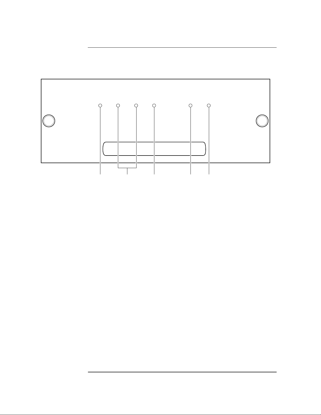
Z3801A Front Panel at a Glance
Z3801A Front Panel at a Glance
I N C O R P O R A T E D
Power
Enabled Active
123 45
1 When the Power indicator is illuminated, it
indicates that the proper input power is
supplied to the Receiver.
2 User-definable indicators labeled Enabled and
Active. These can be turned on through the
RS-422 port.
3 When the Alarm indicator is illuminated, it
indicates that the receiver has detected an
internal condition that requires attention.
GPS RECEIVER
Alarm
GPS Lock
4 When the GPS Lock indicator is illuminated, it
indicates that the Receiver is receiving the
GPS signal and is locked on one or more
satellite(s).
5 When the Holdover indicator is illuminated, it
indicates that the Receiver is NOT locked to
the GPS signal. The Receiver is keeping time
based on the internal reference oscillator
signal. The internal reference oscillator will
determine the accuracy of the 1 PPS signal
and the 10 MHz reference output. (See
specification for Accuracy in Holdover in
Chapter 5, “Specifications Summary,” in this
guide.)
Holdover
1-2 User Guide
Page 15

Chapter 1 Getting Started
Z3801A Rear Panel at a Glance
Z3801A Rear Panel at a Glance
1
2
ANTENNA
J1 J2
!
I/O
Port 1
J3
4
10 MHz OUT
SERIAL PLATE
Made in U.S.A.
with domestic and
foreign content.
!
NRTL/C
TESTED TO UL 1950
WARNING:
To avoid electric shock:
Do not remove covers.
No user serviceable parts inside.
Refer all servicing to qualified personnel.
This unit must be earth grounded.
CAUTION
METRIC & INCH HARDWARE
CONSULT SERVICE MANUAL
DC INPUT
!
BTS
CV90 - 15357 - 1
19.5 - 30VDC
BSC
CV90 - 15357 - 2
38 - 60VDC
3
J4
E1
5
1 ANTENNA J1 N-type (female) connector.
2 10 MHz OUT J2 BNC (female) output connector
for user-specific applications.
3 DC INPUT J4 power connector.
User Guide 1-3
4 I/O Port 1 J3 25-pin female D Subminiature
RS-422 serial interface port for remote
control, monitoring, and retrieving of the
unit’s memory data. This port also provides
two 1 PPS time outputs, and two 10 MHz
frequency outputs.
5 E1 Ground stud provides a low impedance
ground for safety and systems grounding.
WARNING: Ground stud must be connected
to Safety Earth Ground.
Page 16

Chapter 1 Getting Started
Preparing the GPS Receiver for Use
Preparing the GPS Receiver for Use
To Assemble and Install the Antenna System
CABLE CONSIDERATIONS. When using the antenna cables with the
GPS Receiver, you should observe certain precautions. Consult your
local electrical and building ordinance codes on how to install RG-213
cables (58518A/519A) or LMR 400 cables (58520A/521A). Certain
codes might require you to put the cables inside a conduit, or to use
cables made with a non-toxic fire retardant insulation.
To assist you with installing your GPS antenna system, refer to the
following documents:
• Information Notes that provide installation procedures for the
applicable GPS antenna and accessories that you purchase.
• The subsection titled “ANTENNA Input” in Chapter 2, “Features
and Functions,” of this guide.
To Assemble the DC Power Connector
1 Note that you will have to assemble your own dc power cable using
18 AWG connecting wires and a three-pin AMP Universal
MATE-N-LOKII® (female) connector plug (shown in Figure 1-1).
4
1
2
3
1 dc supply (+)
3 dc supply (-)
2 Not used
Figure 1-1. Three-Pin Plug Pinouts (Front View)
2 From the rear of the plug, connect the supply-side wire of the external
power supply or battery to pin 1 of the plug. Connect the external
1-4 User Guide
4 Cable wires
Page 17

Chapter 1 Getting Started
Preparing the GPS Receiver for Use
battery’s return (ground) wire to pin 3. Use the rear-panel E1 ground
stud to connect the GPS Receiver chassis to a system ground.
3 Observing the correct polarity, attach the other ends of the wires to a
proper dc power source to operate the Receiver.
NOTE Do not apply power to the Receiver unless a fully operational antenna
system is connected to the rear-panel ANTENNA J1 connector.
Power applied with no antenna input can initiate an extended search
process that may increase time to reach GPS lock. You can halt the
extended search by disconnecting and reconnecting (cycling) the
external dc supply (you may need to leave power disconnected for
greater than five seconds).
User Guide 1-5
Page 18

Chapter 1 Getting Started
Powering Up the Receiver
Powering Up the Receiver
Overview of the Power-Up Procedure (What to
Expect)
When you power up the GPS Receiver for the first time, you should
expect it to run through the following sequence:
• goes through internal diagnostics and all front-panel lights flash,
• acquires and tracks four satellites,
• computes the Receiver’s position,
• locks to the 1 PPS (one pulse-per-second) time standard provided by
GPS, and
• begins steady-state operation, acting as a source of timing and
synchronization information derived from the GPS standard.
Elapsed time for each step will vary, depending largely on how many
satellites your antenna is able to “see” when you power up. If many
satellites are visible when you power up, the Receiver will take at least
8 minutes and at most 25 minutes to calculate its position from the
constellation of satellites overhead. The derived position will be
improved over a period of time by further averaging. When the
GPS Lock indicator lights, the basic functionality of the Receiver is
available; however, optimal performance is delivered later.
To Power Up the Receiver
1 Connect the antenna system to the rear-panel ANTENNA J1 Type-N
connector of the Receiver as described in the instructions given in the
subsection titled “To Assemble and Install the Antenna System” on
page 1-4 of this chapter.
NOTE Although connecting the GPS Receiver to a terminal or computer isn’t
necessary for it to attain GPS lock, the terminal is needed for you to
observe the progress of the Receiver or to configure alarms.
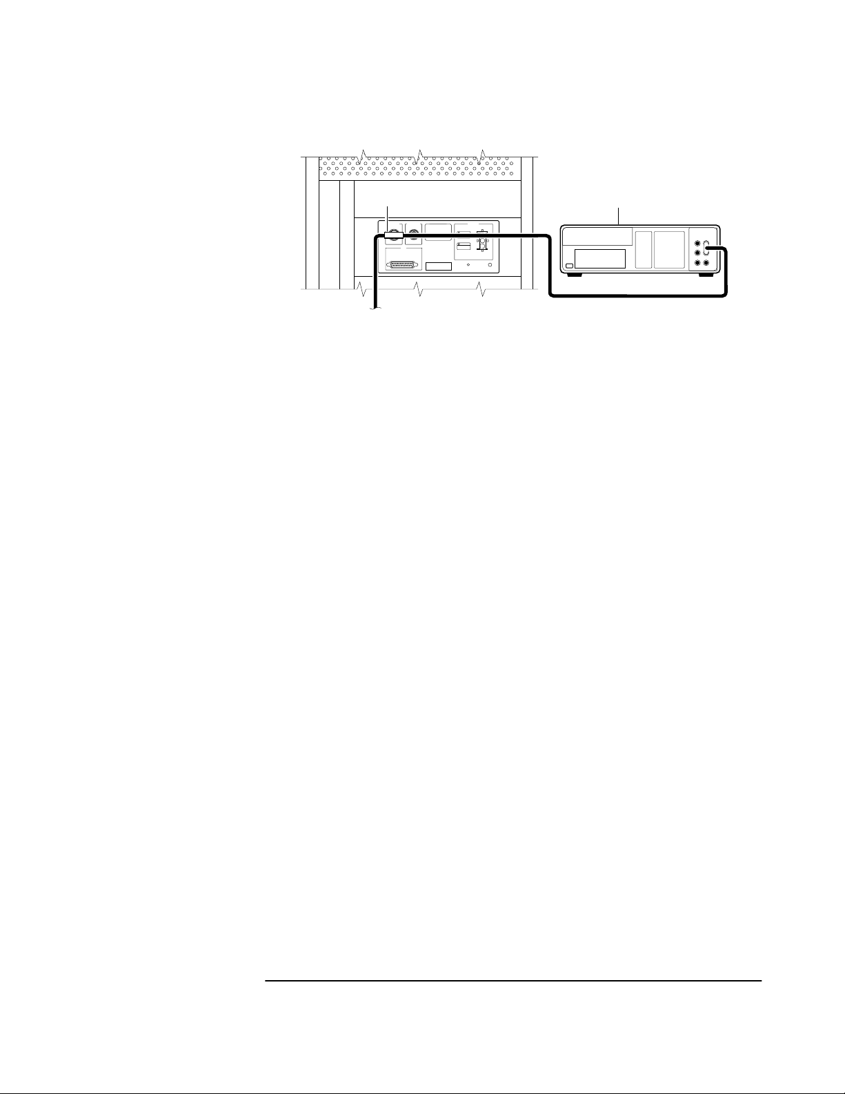
2 Connect the GPS Receiver to your system DCE device (Digital
Communications Equipment) via the rear-panel I/O Port 1 J3
RS-422 port using an appropriate (customer supplied) system interface
cable as shown in Figure 1-2.
1-6 User Guide
Page 19

Chapter 1 Getting Started
Powering Up the Receiver
NOTE Do not apply power to the Receiver unless a fully operational antenna
system is connected to the rear-panel ANTENNA J1 connector.
Power applied with no antenna input can initiate an extended search
process that may increase time to reach GPS lock. You can halt the
extended search by disconnecting and reconnecting (cycling) the
external dc supply (you may need to leave power disconnected for
greater than five seconds).
GPS Receiver
(Rear view)
DCE Device
Figure 1-2. Connecting the GPS Receiver to a DCE Device
(DTE-to-DCE Interface cable is customer supplied)
3 Turn your DCE device (or PC equipped with a correctly wired RS-422
serial-port connector) on.
You will need to run a terminal emulation program on your DCE device
in order to communicate via the RS-422 serial port. Most PCs contain a
terminal emulation program, especially PCs with Windows
application. If your PC does not contain a terminal emulation program,
purchase one of the following programs: PROCOMM PLUS
(DATASTORM Technologies, Inc.®), PROCOMM PLUS for Windows,
Cross Talk (Hayes®), or any other terminal emulation program.
(Note: Symmetricom is not endorsing any of these products.)
Another option to purchasing and installing a terminal emulation
program is to use the SatStat Program. See the section titled
“Installing the Automated SatStat Program for Continual Status
Updates” on page 1-11 for installation and operating information.
User Guide 1-7
Page 20

Chapter 1 Getting Started
Powering Up the Receiver
4 Set the RS-422 port of your DCE device (or PC) to match the following
values:
Pace: NONE
Baud Rate: 19200
Parity: Odd
Data Bits: 7/char
Start Bits: 1
Stop Bits: 1
NOTE The RS-422 port configurations of the Receiver and the DCE device/PC
must be the same for communications between the two. Thus, for this
power-up procedure, set your DCE device/PC to match the default
values listed above.
5 Apply the proper power source to the rear-panel Power input jack of the
Receiver. (See the appropriate subsection titled “To Assemble the DC
Power Connector” on page 1-4)
The following sequence of events occurs after power is applied to the
Receiver.
a. Only the front-panel Power indicator lights.
b. After a moment, the Receiver runs through its self-test diagnostics
as indicated by the flashing front-panel indicators.
c. After the self test is completed, just the Power indicator remains lit.
If the Alarm indicator lights, a failure may have occurred during the
self test. Refer to Table 4-2 in Chapter 4, “Command Listing and
Status Information,” of this guide for information on the Alarm
capability.
d. The Receiver begins to search the sky for all available satellites.
1-8 User Guide
Page 21

Chapter 1 Getting Started
Powering Up the Receiver
e. From the DCE device keyboard, type
:SYSTEM:STATUS? and press Enter (or Return).
Confirm that the scpi> prompt is displayed after pressing Return.
If no prompt or an error-number prompt (E-xxx>) is displayed, then
try typing the command again.
The computer displays the status screen as shown in the sample
status screen in Figure 1-3.
You must re-enter the :SYSTEM:STATUS? command each
time you want an updated status screen.
NOTE You have been provided a Windows program called SatStat, which
provides continual status updates of the GPS Receiver’s status screen.
If you are using an RS-422 equipped PC, it must have Windows
installed to operate the user interface application. The application is
easy to install and operate.
See the section titled “Installing the Automated SatStat Program for
Continual Status Updates” on page 1 in this guide.
f. When four or more satellites are tracked as will be indicated in the
status screen, automatic position computation is initiated.
g. Finally, the Receiver goes into steady-state operation (which
requires one satellite) and the GPS Lock indicator lights, indicating
the Receiver has locked on to the GPS signal.
After the initial powerup, the Receiver is set for basic operation.
That is, the Receiver operating parameters are set to their powerup
default values or states.
If you need to customize the Receiver operation, see the section titled
“Customizing the Receiver Operation” on page 1-13 for a list of key
things you may want to perform to customize the operating parameters
of the Receiver.
User Guide 1-9
Page 22

Chapter 1 Getting Started
Powering Up the Receiver
---------------------------- ----------------------------
SYNCHRONIZATION
SmartClock Mode
Locked to GPS: stabilizing frequency...
>>
Recovery
Holdover
Power-up
ACQUISITION
Satellite Status
Tracking: 5
PRN El Az
ELEV MASK
HEALTH MONITOR
Self Test: OK | Int Pwr: OK Oven Pwr: OK OCXO: OK EFC: OK GPS Rcv: OK
El
2
70
337
7
46
188
15
33
19
28
113
27
65
10
Az
82
91
.........................
.......................................
Not Tracking: 4
PRN
SS
134
117
54
29
128
12 11 292
16 24 243
*26 Acq..
31 -- ---
*attempting to track
......................................................
Receiver Status
[
Outputs Valid/Reduced Accura
Reference Outputs
TFOM
FFOM
1PPS TI
HOLD THR
Time
GPS
1PPS CLK Synchronized to GPS Ti
ANT DLY
Position
MODE
AVG LAT
AVG LON
AVG HGT
3
0
+20 ns relative to GPS
1.000 us
[GPS 1PPS CLK Accurate]
03:56:44 1994 DEC 01
120 ns
Survey: 57.3% complete
NW37:19:31.330
121:59:50.468
+54.89 m (MSL)
cy ]
[ OK ]
Figure 1-3. Sample Status Screen
To Understand the Receiver Status Screen Data
me
One of the key indicators on the screen is the ACQUISITION
status indicator. It shows “GPS 1 PPS Valid ” as soon as satellite
information is sufficient.
Refer to Chapter 3, “Using the Receiver Status Screen,” in this guide
for a tutorial on how to use the status screen (shown in Figure 1-3).
A reference section that defines the different data indicated in the
status screen is also provided in Chapter 3.
1-10 User Guide
Page 23

Chapter 1 Getting Started
Installing the Automated SatStat Program for Continual Status
Updates
Installing the Automated SatStat Program for Continual Status Updates
This Windows application provides continual status updates of the
Receiver Status screen. Your PC must be equipped with a correctly
wired (See Table 2-3 in Chapter 2.) RS-422 serial-port adapter and
have Windows installed to operate the user interface application. The
application is easy to install and operate.
1 Insert the SatStat disk in drive A.
2 From the File menu in either the Program Manager or File Manager,
choose Run.
3 Type a:setup, and press Enter (or Return). The SatStat Setup screen
will appear, and installation will proceed.
4 Once the program is installed, you can start it by double-clicking the
SatStat icon that was created during the installation.
5 You should establish communication with the GPS Receiver.
This requires connection from the DCE device (Digital
Communications Equipment) via the rear-panel I/O Port 1 J3 RS-422
port using an appropriate (customer supplied) system interface cable.
Assuming you’ve got the cable attached to make this connection, you
may want to check the settings.
a. Select CommPort, then choose Settings.
The Communication Settings dialog box is displayed.
Unless someone has reprogrammed the CommPort settings on the
GPS Receiver, these settings are probably OK. The one setting that
is likely to need changing is the Com Port. The application defaults
it to Com1, but the serial port on your PC may be assigned to a
different Com Port. Select the appropriate setting. If you are unsure,
Com1 will be your best bet (worst case, you can cycle through all of
them until it works).
b. If you made any changes on this Settings form, select OK,
otherwise you can just Cancel.
User Guide 1-11
Page 24

Chapter 1 Getting Started
Operating the Automated SatStat Program
Operating the Automated SatStat Program
1 Select CommPort, then choose Port Open.
The main form of the Receiver Status screen is displayed. The program
will send some commands to the GPS Receiver and then the main form
should begin to periodically update every few seconds. If you are
getting screen updates, proceed to the next step. Otherwise, something
is wrong with your CommPort settings or perhaps the physical
connection between your PC and the Receiver.
If you need to control the Receiver or query for the status of a setting of
the Receiver, use the “Control & Query” form (this form will usually be
stacked beneath the main form). To activate this form, click anywhere
on it. Select Control (or Query), then choose the type of control (or
query) you want. This will pull down a list of control (or query)
functions that you can choose from, and the corresponding command
will be displayed. To send the command, click on Send Cmd. Hence,
with the Control & Query form you can control the Receiver without
knowing the command or query.
More information about the Windows program is provided in the
“Getting Started” Help file.
2 Refer to the section titled “Using and Reading the Receiver Status
Screen” in Chapter 3, “Using the Receiver Status Screen,” of this guide
for a tutorial and demonstration of what to look for when viewing the
status screen.
1-12 User Guide
Page 25

Chapter 1 Getting Started
Customizing the Receiver Operation
Customizing the Receiver Operation
Here are some key things you might want to perform to customize the
Receiver operation:
• Execute a system preset if you've found the Receiver in an
unknown or questionable operating state.
• Make the Receiver survey if it wasn’t already surveying.
• Set the antenna delay.
• Set the elevation mask angle.
• Set the time zone.
See the section titled “Using Commands to Control Key Functions
(Examples)” on the following page for more information.
User Guide 1-13
Page 26

Chapter 1 Getting Started
Using Commands to Control Key Functions (Examples)
Using Commands to Control Key Functions
(Examples)
The operation of the GPS Receiver is designed to be as automatic as
possible. However, there are several situations where serial interface
control is required. The tasks described here are those most commonly
encountered.
For each task in this section, you can use either a terminal emulation
program or the SatStat program to issue the selected commands.
Additional information about the commands is provided in Chapter 4,
“Command Listing and Status Information,” of this guide.
To Perform Basic Installation and Simple
Customizing
After connecting the Receiver to the antenna, power source, DCE
device RS-422 port, and after the self test is completed, you may want
to complete installation using one or more of the capabilities described
below.
If required, restore all of the Receiver’s internal settings to
their factory shipment values by invoking a system preset.
After executing the system preset, the Receiver will begin normal
operation: it will acquire GPS signals, determine the date, time, and
position automatically, bring the reference oscillator ovens to a stable
operating temperature, lock the reference oscillator and its output to
10 MHz, and synchronize the 1 PPS output to UTC.
Settings affected by system preset are listed in Chapter 4, “Command
Listing and Status Information,” of this guide under the
:SYSTEM:PRESET command definition.
The Receiver is preset using the command:
:SYSTEM:PRESET
Note that system preset should be performed only when necessary.
1-14 User Guide
Page 27

Chapter 1 Getting Started
Using Commands to Control Key Functions (Examples)
Initiate “surveying”, an automatic determination of the
Receiver’s antenna position.
When “position survey” is invoked, the Receiver is set to ascertain the
position of its antenna automatically. This survey is important; correct
antenna position data is required for the Receiver to deliver specified
performance.
The Receiver uses data from orbiting satellites to survey; hence, the
antenna must be installed and operational for the survey to work.
However, if you have a limited view of the sky, you can complete basic
installation, then read forward to the section titled “To Install With a
Limited View of the Sky, To Bypass Position Survey Operation” on
page 1-16 for a means of overriding the survey operation and entering
position data directly.
The survey is an iterative process. The Receiver transits to “Position
Hold” when a usable position has been obtained.
Set the Receiver to survey using command:
:PTIME:GPSYSTEM:POSITION:SURVEY ONCE
Set the Receiver to compensate for the length of the
antenna cable.
The Receiver can be custom-configured to compensate for the length of
the antenna cable. The phase of the Receiver’s internal clock is
therefore offset from the GPS standard by the number of nanoseconds
of delay introduced through the antenna cable. The amount of error is
typically on the order of a few hundred nanoseconds. Should you decide
to correct for this error, Table 2-1A and Table 2-1B in Chapter 2,
“Features and Functions,” of this guide provides typical corrections for
standard antenna cable lengths.
Set the Receiver to compensate for antenna cable delay using
command:
:PTIME:GPSYSTEM:ADELAY <seconds>
or
:PTIME:GPSYSTEM:ADELAY <nanoseconds> NS
It is normal to observe that the Receiver momentarily goes into
holdover after any change in antenna delay.
User Guide 1-15
Page 28

Chapter 1 Getting Started
Using Commands to Control Key Functions (Examples)
Set the Receiver to exclude satellites which appear below a
specified elevation angle.
At the factory, and whenever the Receiver is preset, the Receiver is set
to seek satellites visible from zenith down to 10 degrees above the
horizon—down to an “elevation mask angle” of 10 degrees. The factory
elevation mask angle setting is intended to provide a full view of the
sky. The Receiver can be custom-configured to use a different elevation
mask angle.
Set the Receiver elevation mask angle using the command:
:PTIME:GPSYSTEM:EMANGLE <degrees>
Set the Receiver to display local time rather than
UTC time.
Set the offset from UTC time to local time using the command:
:PTIME:TZONE <hours>, <minutes>
To Install With a Limited View of the Sky, To Bypass
Position Survey Operation
In order to reach steady-state operation, the Receiver must know the
position of the antenna. The Receiver is able to collect enough
information from four satellites to compute this position. The “position
survey operation” takes in data from the satellites, iterating until the
antenna position is known to the required precision. The Receiver will
automatically use its position survey operation on powerup and
:SYSTEM:PRESET.
Alternatively, if the antenna position is already known to seconds of
arc, and the Receiver cannot see enough satellites, you may manually
enter antenna position as shown in the following text.
NOTE An incorrect value for the position will confuse the Receiver, and will
degrade the timing information accuracy or even prevent tracking any
satellites.
Set the Receiver antenna position using the command format shown
below (for clarity, an example is provided rather than a complex
description.):
:PTIM:GPS:POS N,37,19,32.5,W,121,59,51.2,40.12
1-16 User Guide
Page 29

Chapter 1 Getting Started
Using Commands to Control Key Functions (Examples)
Set the latitude, longitude, and height parameters to represent the
latitude (in degrees, minutes, seconds), longitude (in degrees, minutes,
seconds), and altitude in meters above mean sea level (MSL). (Note: if
you know the position to this accuracy, the desired position is of the
antenna rather than the Receiver.)
NOTE For faster acquisition following repair, or power failure you may want
to write down the position after the Receiver has completed its survey.
User Guide 1-17
Page 30

Chapter 1 Getting Started
Using Commands to Control Key Functions (Examples)
1-18 User Guide
Page 31

2
Features and Functions
Page 32

Chapter 2 Features and Functions
Chapter Contents
Chapter Contents
You will find that this section makes it easy to look up all the details
about a particular feature of the Z3801A GPS Receiver. This chapter
provides inputs, outputs, indicators, terminal and computer
connections, operating concepts (GPS lock and holdover), and
problem-solving information.
This chapter is organized as follows:
• Inputs page 2-3
– ANTENNA Input page 2-3
– DC INPUT J4 Power Jack page 2-6
• Outputs page 2-7
– 10 MHz OUT J2 Output page 2-7
– 10 MHz Outputs—via I/O Port 1 J3 page 2-7
– 1 PPS (One Pulse Per Second) Outputs— via I/O
Port 1 J3
– RS-422 Serial Port, I/O Port 1 J3 page 2-8
• Indicators page 2-9
– Power Indicator page 2-9
– Enabled/Active Indicator page 2-9
– Alarm Indicator page 2-9
– GPS Lock Indicator page 2-9
–Holdover Indicator page2-9
• Connecting to a Computer page 2-10
• Operating Concepts page 2-11
– General page 2-11
– Holdover Description page 2-11
• In Case of a Problem page 2-12
page 2-7
2-2 User Guide
Page 33

Chapter 2 Features and Functions
Inputs
Inputs
ANTENNA Input
The N-type (female) ANTENNA connector allows you to connect the
58504A or 58513A Antenna Assembly. The antenna assemblies are
“active” antennas; a “passive” antenna will not work with the Receiver.
Integral to the antenna assembly is a low noise amplifier (LNA) that is
provided for Receiver operation with antenna cable lengths up to
378 feet (115.2 meters) for LMR 400 cables or 175 feet
for RG-213 cables. The single coax cable is used to provide signals from
the antenna to the Receiver and to supply a dc voltage to the LNA.
For longer antenna feed runs, an additional amplifier (58509A
Antenna Line Amplifier) is required to compensate for lengths greater
than 378 feet (115.2 meters) or 175 feet (53.3 meters).
An environmental cover that shields the antenna from wind, rain, and
snow, and a ground plane that prevents problems with reflected
signals is available as the 58510A—or combined in the 58513A.
1
(53.3 meters)
Refer to Chapter 1, “Getting Started,” in this guide for information on
the components of the antenna system and installation instructions.
Recommended Antenna Cable Assemblies
There are two types of cable assemblies that we recommend you use to
connect your antenna system: LMR 400 or RG-213 (Belden® 8267).
The following paragraphs describes when and how many line
amplifiers are required with the LMR 400 and RG-213 cables.
1
One hundred and seventy-five feet includes the sum total of all of the cables used to connect the
antenna to the (such as the cable between the antenna and line amplifier, the cable between the line
amplifier and lightning arrester, and the cable between the lightning arrester and the ).
User Guide 2-3
Page 34

Chapter 2 Features and Functions
Inputs
LMR 400 Cable Line Amplifier Requirements
If cable length between GPS Receiver and antenna is:
• Less than 115 meters (377 feet), no line amplifier is necessary.
• More than 115 meters (377 feet) and less than 240 meters
(787 feet), you need 1 line amplifier.
• More than 240 meters (787 feet) and less than 360 meters
(1181 feet), you need 2 line amplifiers.
• More than 360 meters (1181 feet), contact sales/support for
assistance.
RG-213 Cable Line Amplifier Requirements
If cable length between GPS Receiver and antenna is:
• Less than 53 meters (174 feet), no line amplifier is necessary.
• More than 53 meters (174 feet) and less than 105 meters (345 feet),
you need 1 line amplifier.
• More than 105 meters (345 feet) and less than 158 meters
(518 feet), you need 2 line amplifiers.
• More than 158 meters (518 feet), contact sales/support for
assistance.
2-4 User Guide
Page 35

Chapter 2 Features and Functions
Inputs
Antenna Cable Length Delay
The RG 213 propagation delay is 1.54 nanoseconds per foot
(5.05 ns/meter). The LMR 400 propagation delay is 1.2 nanoseconds
per foot (3.93 µs/meter). Given these delay values per foot you can
calculate the delay for your cable length.
Tables 2-1A and 2-1B list the delay values that you need to use with
the :GPSYSTEM:REFERENCE:ADELAY <seconds> command for the
available the cable assemblies.
Table 2-1A. Delay Values for the 58518A/519A and 58518AA/519AA
RG-213 Antenna Cables
Cable Option Length RG 213 or Belden 8267
Antenna Delay Value
001 3.3 ft (1m) 5.0 nanoseconds
002 6.7 ft (2 m) 10.3 nanoseconds
005 16.4 ft (5 m) 25.2 nanoseconds
010 32.8 ft (10 m) 50.5 nanoseconds
015 49.2 ft (15 m) 75.7 nanoseconds
030 98.4 ft (30 m) 151.5 nanoseconds
050 164.0 ft (50 m) 252.5 nanoseconds
The nominal delay value is labeled on the cables. Refer to the
Designing Your GPS Antenna System Configuration Guide
(P/N 5964-9068E for more information.)
User Guide 2-5
Page 36

Chapter 2 Features and Functions
Inputs
Table 2-1B. Delay Values for the 58520A/521A and 58520AA/521A
LMR 400 Antenna Cables
Cable Option Length LMR 400 Antenna Delay
Value
001 3.3 ft (1m) 3.9 nanoseconds
002 6.7 ft (2 m) 8.0 nanoseconds
005 16.4 ft (5 m) 19.6 nanoseconds
010 32.8 ft (10 m) 39.3 nanoseconds
015 49.2 ft (15 m) 59.0 nanoseconds
030 98.4 ft (30 m) 118.0 nanoseconds
060 196.8 ft (60 m) 236.1 nanoseconds
110 360.8 ft. (110 m) 432.9 nanoseconds
The nominal delay value is labeled on the cables. Refer to the
Designing Your GPS Antenna System Configuration Guide
(P/N 5964-9068E for more information.)
DC INPUT J4 Power Jack
The DC INPUT J4 jack allows you to connect a BTS 19.5-30.0 Vdc or
BSC -38 to -60 Vdc power source to drive the Receiver.
Table 2-2 lists the input jack pin assignments. This jack is used for DC
power only.
Table 2-2. DC INPUT J4 Power Connections
Pin Number Signal Name
1 dc supply (+)
3 dc return (−)
See Figure 1-1 in Chapter 1, “Getting Started,” in this guide for an
illustration of the AMP Universal MATE-N-LOKII® dc power jack.
2-6 User Guide
Page 37

Chapter 2 Features and Functions
Outputs
Outputs
10 MHz OUT J2 Output
This is a 10 MHz output reference signal traceable to UTC (USNO)
that can be used for synchronizing CDMA test equipment.
10 MHz Outputs—via I/O Port 1 J3
Two additional 10 MHz synchronization signals are available through
the I/O Port 1 J3 connector. Refer to Table 2-3 for signal characteristics
and connector pin assignment information.
1 PPS (One Pulse Per Second) Outputs—
via I/O Port 1 J3
The Receiver outputs two highly accurate 1 PPS time standard outputs
for user-specific synchronization applications. Refer to Table 2-3 for
signal characteristics and connector pin assignment information.
In the GPS locked mode, the Receiver outputs a 1 PPS signal derived
from the internal oscillator, which is locked and traceable back to
Coordinated Universal Time (UTC) as determined by GPS. In the
absence of GPS, the 1 PPS signal will continue to exist, but the
oscillator will go into a holdover mode in which the SmartClock™
algorithm will compensate for the instabilities in the oscillator. In the
holdover mode, the timing 1 PPS accuracy will degrade as the holdover
time increases.
User Guide 2-7
Page 38

Chapter 2 Features and Functions
Outputs
RS-422 Serial Port, I/O Port 1 J3
The 25-pin female D Subminiature (DB-25) connector located on the
rear panel provides RS-422 serial communications capability.
This can be used by connecting a DCE device with an RS-422 serial
interface port (wired to interface with the receiver's I/O port as listed in
Table 2-3) and suitable terminal emulation software, then sending the
correct commands for transmitting or retrieving data. You can
customize the Receiver on installation, to change the Receiver’s
operating characteristics, retrieve Receiver state information, and
clear the stored data. The pins used are described in Table 2-3.
Table 2-3. Rear-Panel RS-422 Serial Port/10 MHz/1PPS Pin
Assignments
*Pin Number Input/Output Description
1 Cable Shield
2 (A),
14 (B)
3 (A),
16 (B)
7 ——— Signal Ground (SG)
15
12
11
24
17
9
8
21
*All other pins, no connection.
Output Transmit Data (TxD)—GPS Receiver
output RS-422 (per RS-530)
Input Receive Data (RxD)—GPS Receiver
input RS-422 (per RS-530)
10 MHz_1-
10 MHz_1+
10 MHz_2-
10 MHz_2+
1 PPS/_1-
1 PPS/_1+-
1 PPS/_2-
1 PPS/_2+
Differential pseudo ECL
10 MHz output
Differential pseudo ECL
10 MHz output
Differential pseudo ECL
1 PPS output
Differential pseudo ECL
1 PPS output
2-8 User Guide
Page 39

Chapter 2 Features and Functions
Indicators
Indicators
Power Indicator
This indicator lights when the input power is supplied to the Receiver.
Enabled/Active Indicator
These user definable indicators light when turned on through the
RS-422 serial interface port.
Alarm Indicator
The Receiver lights this indicator to indicate it has detected an internal
condition that requires attention.
Refer to Table 4-2 in Chapter 4, “Command Listing and Status
Information” of this guide for information on Alarm capability.
GPS Lock Indicator
This indicator lights when the Receiver is tracking satellites and
phase-locked its internal reference to the reference time derived from
satellite data. This indicator will go off whenever the above condition is
not met, which would typically occur when satellite tracking is lost or
while the Receiver is powering up.
The principal Receiver setting that can affect this indication is manual
selection of reference oscillator holdover operation.
Holdover Indicator
The Receiver lights this indicator to show that GPS lock has been lost
and the Receiver is in holdover mode. It only lights it the Receiver has
been locked once; it will never light until the Receiver has been locked
once. While in holdover, the internal reference oscillator will be
adjusted by SmartClock™ technology .
NOTE If the Holdover indicator lights before the Receiver has been locked
24 hours, then the Receiver has not had sufficient time to learn the
characteristics of the internal reference oscillator. In this case, the
specification for Timing Accuracy during holdover may not be met.
This specification applies only after the Receiver has had sufficient
stable operation time.
Refer to the subsection titled “Holdover Description” on page 2-11 in
this chapter for more information.
User Guide 2-9
Page 40

Chapter 2 Features and Functions
Connecting to a Computer
Connecting to a Computer
To connect the GPS Receiver to a computer, you must have an
appropriately wired RS-422 interface cable (customer supplied).
Refer to Table 2-3 for rear-panel I/O Port 1 J3 pin assignments and
signal characteristic information.
The interface cable must also have the proper connector on each end
and the internal wiring must be correct. The GPS Receiver is
considered the Data Terminal Equipment (DTE) for this interface.
The Z3801A rear-panel serial interface port has a fixed configuration
as described in Chapter 1 of this guide on page 1-3.
2-10 User Guide
Page 41

Chapter 2 Features and Functions
Operating Concepts
Operating Concepts
General
The time required to acquire GPS lock as described in the following
paragraph can vary significantly depending on your local conditions.
In general, we strongly recommends that your antenna and cables be
set up in accordance with the information provided in this guide prior
to using the output signals of the Receiver to ensure they are valid.
Acquiring lock does not mean that the Receiver is fully operational and
meeting all specifications. It just means that the Receiver has detected
enough satellites to start its survey mode to determine its precise
location. An internal measurement FFOM (Frequency Figure of Merit)
becomes 0 when the internal loops reach their proper time constants,
indicating that the output frequency and 1 PPS signals are now fully
operational and meeting their specifications. Under the worst
conditions, the Receiver may take up to 24 hours to achieve FFOM = 0.
FFOM can be monitored in the Reference Outputs quadrant of the
Receiver Status screen (see Figure 3-1 in Chapter 3, “Using the
Receiver Status Screen,” of this guide). Also, using the appropriate
SCPI query command will provide FFOM value (refer to Chapter 4,
“Command Listing and Status Information,” in this guide for specifics).
The Receiver is designed to automatically detect and acquire satellites
in order to begin providing precise frequency and time information.
Until such acquisition is complete and the instrument is locked with
FFOM = 0, the signals produced on the rear panel are not precise.
Holdover Description
If the GPS signal is interrupted, the Receiver enters an intelligent
holdover mode that uses SmartClock® technology. SmartClock takes
over control of the quartz oscillator that has been steered to the GPS
reference during locked operation. SmartClock predicts the
performance of the quartz oscillator based on the information gathered
during the “learning period” (locked to GPS). Corrections are
automatically issued over time, keeping the performance of the quartz
oscillator as close as possible to the performance achieved while locked
to the GPS reference signal.
Holdover frequency is maintained to better than <1 × 10
The time specifications 1 µs locked, and 7µs unlocked for 24 hours.
When the GPS reference signal is restored, the Receiver automatically
switches back to normal mode of operation.
-9
per day.
User Guide 2-11
Page 42

Chapter 2 Features and Functions
In Case of a Problem
In Case of a Problem
Hours after powerup, Receiver not establishing
GPS lock
SYMPTOM
Solution Check antenna:
Date, time, and position still show power-up defaults, or these
parameters are incorrect.
Receiver Position Mode = Survey.
Receiver cycling from one set of satellites to another.
No satellites consistently tracked.
• Verify antenna has an unobstructed view of the sky—antenna is
not under or beside an impervious object.
• Verify antenna is connected.
• Verify antenna is connected properly:
– cable run not too long.
– cable with antenna attached neither shorted nor open.
• Verify antenna is being properly driven—Hint:
(1) connect Tee-connector to Receiver’s rear-panel ANTENNA J1
input; connect antenna cable to one end of Tee. Measure a little
less than +5 Volts from the other end of the Tee using a digital
voltmeter (DVM) as shown in Figure 2-1. If your reading is a lot
less than +5 Volts, you will have to determine if the line
amplifier or lightning arrester is at fault by using conventional
troubleshooting isolation techniques. If the line amplifier and
lightning arrester are good, then the antenna may be faulty.
(2) If the Receiver +5 Volts is okay, check +5 Volts at the antenna
end of the cable with a voltmeter connected between the center
conductor and shell. If insufficient voltage is present, it may
indicate that the shield of the cable is not making adequate
contact to one of the cable connectors.
• After the antenna connection has been verified, cycle power on the
Receiver to facilitate rapid recovery from the fault.
NOTE Remove the Tee connector and restore antenna connection as loading of
the Tee connector will prevent proper reception of the GPS signal by
the antenna.
2-12 User Guide
Page 43
Chapter 2 Features and Functions
In Case of a Problem
SYMPTOM
SOLUTION
SYMPTOM
SOLUTION
1
1 Tee-connector 2 DVM
2
Figure 2-1. Measuring +5 Volts Across Antenna Input
Same as previous symptoms, except Receiver Position Mode = Hold.
Enable SURVEY mode using specified command.
Receiver not maintaining GPS lock
Position data incorrect.
Survey to obtain correct position,
or
SYMPTOM
SOLUTION
Correct position data using specified command.
Position data correct.
Sufficient satellites in view.
No satellites tracked.
If candidate satellites are marked “Ignore” on status screen, disable
the feature which ignores satellites.
If candidate satellites are below the mask angle specified on Receiver
Status screen, reset the elevation mask angle. Default is 10 degrees—
all satellites between the horizon and 10 degrees of the horizon are
masked.
User Guide 2-13
Page 44

Chapter 2 Features and Functions
In Case of a Problem
2-14 User Guide
Page 45

3
Using the Receiver Status Screen
Page 46

Chapter 3 Using the Receiver Status Screen
Chapter Contents
Chapter Contents
This chapter provides a tutorial section on how to use the Receiver
Status screen, a comprehensive reference information section, and an
illustrated foldout of the Receiver Status screen, which is a
comprehensive summary of key operation conditions and settings.
This chapter is organized as follows:
• Using and Reading the Receiver Status Screen page 3-3
– Tutorial on Using the Status Screen to Interface
With the Receiver
– Demonstration of Holdover Operation page 3-8
• Receiver Status Screen Data page 3-11
– SYNCHRONIZATION Section of the Status
Screen
– ACQUISITION Section of the Status Screen page 3-14
– HEALTH MONITOR Section of the Screen page 3-18
• The Receiver Status Screen at a Glance page 3-20
page 3-4
page 3-12
3-2 User Guide
Page 47

Chapter 3 Using the Receiver Status Screen
Using and Reading the Receiver Status Screen
Using and Reading the Receiver Status
Screen
The Receiver Status screen can be accessed when the GPS Receiver is
connected to a properly configured terminal or PC. There are two ways
to access and use the Receiver Status screen:
• By installing a commercially available terminal emulation
program, connecting the GPS receiver to a DCE device (Digital
Communications Equipment) via the rear-panel I/O Port 1 J3 RS-422
port using an appropriate (customer supplied) system interface
cable, and manually sending the :SYSTEM:STATUS? query. (Refer
to Chapter 1, “Getting Started,” in this guide.)
• By installing and operating the SatStat program which
automatically generates continual status screen updates, and
connecting the GPS Receiver to a PC via via the rear-panel I/O Port 1
J3 RS-422 port using an appropriate (customer supplied) system
interface cable. (Refer to the sections titled “Installing the
Automated HP SatStat Program for Continual Status Updates”
and “Operating the Automated HP SatStat Program” in Chapter 1,
“Getting Started,” of this guide for details on installation.)
The following tutorial demonstrates how you can use the Receiver
Status screen to observe GPS Receiver operation. The tutorial uses the
manual (:SYSTEM:STATUS?) method.
User Guide 3-3
Page 48

Chapter 3 Using the Receiver Status Screen
Using and Reading the Receiver Status Screen
Tutorial on Using the Status Screen to Interface With
the Receiver
Type :SYSTEM:STATUS? at the scpi> prompt.
An initial power-up screen is displayed, which is similar to the
demonstration screen shown in Figure 3-1. The first data that you
should look at is in the SYNCHRONIZATION area of the screen. It is
telling you that it is in the Power-up state as indicated by the >>
marker. That is, the Receiver has just been put on line.
---------------------------- ---------------------------SYNCHRONIZATION
SmartClock Mode
Locked
Recovery
Holdover
>>
Power-up:GPS acquisition
ACQUISITION
Satellite Status
Tracking: 0
ELEV MASK
HEALTH MONITOR
Self Test: OK Int Pwr: OK Oven Pwr: OK OCXO: OK EFC: OK GPS Rcv: OK
10 deg
.........................................
.............................................
Not Tracking: 6
PRN
El Az
*1 -- --*6 -- --*9 -- ---
*14 -- --*22 -- --*24 -- --*attempting to track
......................................................
Receiver Status
[
Reference Outputs
TFOM
1PPS TI
HOLD THR
Holdover Uncertainty
Predict --
Time
UTC
GPS 1PPS Invalid:not tracking
ANT DLY
Position
MODE
INIT LAT
INIT LON
INIT HGT
9
--
1.000 us
12:00:00[?] 01 JAN 1996
0 ns
Survey: 0% complete
Suspended:Track <4 sats
NW0:00:00.000
Outputs Invalid
FFOM
[GPS 1PPS Invalid]
0:00:00.000
0 m (MSL)
[ OK ]
Figure 3-1. Receiver Status Screen at Powerup
The ACQUISITION area of the screen is telling you that no satellites
have been tracked. The identification numbers of several satellites
appear in the Not Tracking column. The asterisk next to the satellite
identification number, or pseudorandom noise code (PRN), indicates
the Receiver is attempting to track it.
]
3
The current time and date are shown in the Time quadrant of the
ACQUISITION area. The default power-up setting, indicated by [?], is
corrected when the first satellite is tracked. Since the Receiver is not
tracking any satellites, the GPS 1 PPS reference signal is invalid.
3-4 User Guide
Page 49

Chapter 3 Using the Receiver Status Screen
Using and Reading the Receiver Status Screen
An accurate position is necessary to derive precise time from GPS. The
Position quadrant indicates that the Receiver is in survey mode, which
uses GPS to determine the position of the GPS antenna. This process
has not yet started, since position calculations can be performed only
while tracking four or more satellites. INIT LAT, INIT LON, and INIT
HGT are the initial estimate of the true position. These coordinates are
refined by the survey process. The Receiver uses this position and the
time-of-day to select satellites to track. Therefore, you can reduce
satellite acquisition time by specifying an close approximation of
position and time.
Now, let’s send the :SYSTEM:STATUS? query again to see what kind
of progress the Receiver has made.
You can now see that the Receiver is tracking several satellites as
shown in Figure 3-2. The process of acquiring and tracking satellites is
described in the following paragraphs.
---------------------------- ----------------------------
SYNCHRONIZATION
SmartClock Mode
Locked to GPS: stabilizing frequency
>>
Recovery
Holdover
Power-up
ACQUISITION
Satellite Status
Tracking: 5
PRN El Az
El
Az
2
70
337
7
46
188
15
33
82
19
28
113
22
65
91
ELEV MASK
HEALTH MONITOR
Self Test: OK Int Pwr: OK Oven Pwr: OK OCXO: OK EFC: OK GPS Rcv: OK
10 deg
...........................
................................................
Not Tracking: 4
SS
PRN
134
117
54
29
128
......................................................
9 11 292
16 24 243
*26 Acq..
31 -- ---
*attempting to track
Receiver Status
[
Outputs Valid/Reduced Accuracy
Reference Outputs
TFOM FFOM
1PPS TI
HOLD THR
Holdover Uncertainty
Predict --
Time
UTC
GPS 1PPS Synchronized to UTC
ANT DLY
Position
MODE
AVG LAT
AVG LON
AVG HGT
61
+71 ns relative to GPS
1.000 us
[GPS 1PPS Valid]
17:56:44 31 Jan 1996
0 ns
Survey: 1.2% complete
NW37:19:34.746
121:59:50.502
+34.14 m (MSL)
[ OK ]
Figure 3-2. Receiver Status Screen Displaying Initial Satellite
Acquisition
]
User Guide 3-5
Page 50

Chapter 3 Using the Receiver Status Screen
Using and Reading the Receiver Status Screen
An asterisk (*) next to the PRN of a satellite in the Not Tracking
column indicates the Receiver is attempting to track it. The elevation
(El) and azimuth (Az) angles of the satellite are indicated. Acq . or Acq..
tell you that the Receiver is attempting to track that satellite. One dot
after the Acq indicator shows that the Receiver is attempting to
acquire its signal, and two dots indicate impending lock. Eventually,
you will see the satellite move from the Not Tracking column, which
shows the satellite PRN, the elevation angle of the satellite in the sky
(90° being zenith), the azimuth angle (number of degrees bearing from
true north), and the signal strength (SS). A good signal strength is a
number above 20, which would be efficient for the Receiver to operate.
Numbers below 20, suggest intermittent tracking of the satellite or no
tracking; check your antenna system should this be the case.
As indicated by the demonstration screen in Figure 3-2, the Receiver is
now surveying for position. It is tracking four satellites which is the
minimum number that must be tracked to determine position. As you
can see, the Position MODE line indicates survey is 1.2% complete.
A complete survey would take two hours during which four satellites or
more are continuously tracked.
Also, you can see the initial (estimated) position has been replaced
with a computed position, which the Receiver continuous to refine until
it gets a very accurate position. The status screen indicates that a
computed position is being used by displaying the averaged latitude,
and longitude height (AVG LAT, AVG LON, and AVG HGT).
If the position were not precise, GPS timing information would be
inaccurate by an amount corresponding to the error in the computed
position. An error in the computed position of the antenna translates
into an error in the derived time and will compromise the Receiver’s
ability to be a timing source.
Let’s consider a case where four satellites are not visible at powerup
because of a poor antenna location, such as an “urban canyon” (located
between tall city buildings). If accurate position is known from a
Geodetic survey of that site, it can be programmed with the position
command, thereby bypassing the survey operation. This is useful when
four satellites cannot be tracked for an extended period of time.
Let’s send the :SYSTEM:STATUS? query again to observe the current
status of the Receiver.
The updated demonstration status screen in Figure 3-3 indicates that
the position survey is now 5.4% complete. Thus, the survey task is
beginning to iterate toward an accurate position. In the Time
quadrant, the UTC time is now correct. The date is correct, and the
GPS reference signal is synchronized to UTC.
3-6 User Guide
Page 51

Chapter 3 Using the Receiver Status Screen
Using and Reading the Receiver Status Screen
---------------------------- ----------------------------
SYNCHRONIZATION
SmartClock Mode
Locked to GPS: stabilizing frequency
>>
Recovery
Holdover
Power-up
ACQUISITION
Satellite Status
Tracking: 6
PRN El Az
El
Az
2
70
301
7
35
186
19
40
102
22
71
60
26
19
317
31 5216 41
ELEV MASK
HEALTH MONITOR
Self Test: OK Int Pwr: OK Oven Pwr: OK OCXO: OK EFC: OK GPS Rcv: OK
10 deg
............................
...............................................
Not Tracking: 1
SS
PRN
82
71
61
84
54
16 13 258
......................................................
Receiver Status
[
Outputs Valid/Reduced Accuracy
Reference Outputs
TFOM FFOM
1PPS TI
HOLD THR
Holdrover Uncertainty
Predict 432.0 us/initial 24 hrs
Time
UTC
GPS 1PPS Synchronized to UTC
ANT DLY
Position
MODE
AVG LAT
AVG LON
AVG HGT
41
+20 ns relative to GPS
1.000 us
[GPS 1PPS Valid]
18:47:07 31 Jan 1996
0 ns
Survey: 5.4% complete
NW37:19:34.937
121:59:50.457
+67.94 m (MSL)
[ OK ]
Figure 3-3. Receiver Status Screen Displaying Progress Towards
Steady-State Operation
]
In the SYNCHRONIZATION area, the >> marker is pointed at the
Locked to GPS line, indicating that the Receiver is locked to GPS and
stabilizing the frequency of its oscillator. This means that the Receiver
has phase-locked its oscillator to the 1 PPS reference signal provided
by GPS, but it is not at its final, or most stable, state. The Receiver is
locked and the front-panel GPS Lock LED is illuminated.
For users without the command interface (PC/Terminal emulator
connected to the Receiver), the illuminated GPS Lock LED is probably
the first indication that after powerup that the Receiver is moving
towards a stable state.
With the command interface and status screen, you can get more detailed
information. For example, you can read the reference outputs quality
indicators in the Reference Outputs area of the status screen. These are
the Time Figure of Merit (TFOM) and Frequency Figure of Merit (FFOM)
indicators. As shown in Figure 3-3, the TFOM is 4 and the FFOM is 1.
These values will eventually decrease towards the ultimate values that
represent steady-state performance. Refer to the subsection titled
“Reference Outputs,” on page 3-13 in this chapter for more information
about TFOM and FFOM.
Also indicated is a prediction of the accuracy of the Receiver should it
go into holdover operation.
User Guide 3-7
Page 52

Chapter 3 Using the Receiver Status Screen
Using and Reading the Receiver Status Screen
Demonstration of Holdover Operation
CAUTION The Receiver typically reaches stable state 24 hours after powerup,
and it will learn best if its experiences no holdover in the first 24 hours.
Therefore, the holdover demonstration in the following paragraphs will
compromise the Receiver’s ability to learn the characteristics of its
internal reference oscillator. For the purpose of education only, you will
be shown how to initiate a holdover.
A user should never initiate holdover during the first 24 hours while
the Receiver is learning its internal oscillator characteristics. The
Receiver should maintain GPS lock during this time because it is using
the GPS signal to discipline the oscillator. It will learn what the
oscillator drift characteristics are relative to the GPS signal. It will
learn how the oscillator ages, and the software will learn how to
compensate for that aging.
Thus, it is recommended that the Receiver is always kept locked to
GPS during the first 24 hours.
For demonstration purposes, and since the Receiver has been powered
up for a while, let’s put the Receiver into holdover by simply removing
the antenna connection. (Note that holdover also can be manually
initiated by sending the SYNCHRONIZATION:HOLDOVER:INITIATE
command; however, for this demonstration, disconnect the antenna
cable.) The following will occur :
• The front-panel Holdover LED will illuminate, and
• after sending the :SYSTEM:STATUS? query again, a screen similar
to Figure 3-4 should appear.
Let’s send the :SYSTEM:STATUS? query. Figure 3-4 should appear.
3-8 User Guide
Page 53

Chapter 3 Using the Receiver Status Screen
Using and Reading the Receiver Status Screen
---------------------------- ---------------------------SYNCHRONIZATION
SmartClock Mode
Locked to GPS
Recovery
Holdover: GPS 1PPS invalid
>>
Power-up
ACQUISITION
Satellite Status
Tracking: 0
ELEV MASK
HEALTH MONITOR
Self Test: OK Int Pwr: OK Oven Pwr: OK OCXO: OK EFC: OK GPS Rcv: OK
10 deg
...........................
Holdover Duration: 0m 14s
.............................................
Not Tracking: 7
El Az
PRN
*2 71 316
*7 41 186
15 11 86
*19 35 107
*22 68 78
*26 23 314
*attempting to track
......................................................
Receiver Status
[
PRN El Az
*31 12 29
Outputs Valid/Reduced Accuracy
Reference Outputs
TFOM FFOM
1PPS TI -HOLD THR
Holdover Uncertainty
Predict 432.0 us/initial 24 hrs
Present 1.0 us
Time
UTC
GPS 1PPS Inaccurate: not tracking
ANT DLY
Position
MODE
LAT
LON
HGT
32
1.000 us
[GPS 1PPS Invalid]
20:56:14 31 Jan 1996
0 ns
Survey: 71.1% complete
NW37:19:32.472
121:59:51.784
+42.19 m (MSL)
[ OK ]
Figure 3-4. Receiver Status Screen Displaying Holdover Operation
In the SYNCHRONIZATION area, you can see that the Receiver has
gone into holdover as indicated by >> marker that is pointing at the
Holdover line. The status screen indicates that the reason the Receiver
is in holdover is because the GPS 1 PPS reference signal is invalid.
]
You would expect this since the antenna has been disconnected.
The status screen shows, instantaneously, loss of the GPS signal.
As you can see on the screen, all of the satellites in the Tracking
column moved into the Not Tracking column.
The status screen in Figure 3-4 shows that the Receiver has been in
holdover operation for 14 seconds.
If the Receiver SmartClock had had enough time to learn the internal
oscillator characteristics (24 hours), the Receiver status screen would
show that the Receiver went into holdover, and the Receiver’s outputs
were maintained during holdover by the SmartClock.
When the GPS antenna is re-connected and the GPS signal has been
re-acquired, the Receiver has the ability to recover from holdover by
itself. The SYNCHRONIZATION area of the screen will show the >>
marker pointing at the Recovery line (and then eventually at the
Locked to GPS line), the GPS Lock LED will illuminate, and the screen
will look similar to Figure 3-5.
User Guide 3-9
Page 54

Chapter 3 Using the Receiver Status Screen
Using and Reading the Receiver Status Screen
---------------------------- ----------------------------
SYNCHRONIZATION
SmartClock Mode
Locked to GPS: Stabilizing frequency
>>
Recovery
Holdover
Power-up
ACQUISITION
Satellite Status
Tracking: 6
PRN
2
7
19
22
26
31 12 27
ELEV MASK
HEALTH MONITOR
Self Test: OK Int Pwr: OK Oven Pwr: OK OCXO: OK EFC: OK GPS Rcv: OK
71
34
41
67
24
Az
317
185
101
80
312
10 deg
............................
...............................................
Not Tracking: 0
SSEl
80
73
64
87
55
49
......................................................
Receiver Status
Outputs Valid/Reduced Accuracy
[
Reference Outputs
TFOM FFOM
1PPS TI +10.6 ns relative to GPS
HOLD THR
Holdover Uncertainty
Predict 432.0 us/initial 24 hrs
Time
UTC
GPS 1PPS Synchronized to UTC
ANT DLY
Position
MODE
LAT
LON
HGT
31
1.000 us
[GPS 1PPS Valid]
20:59:28 31 Jan 1996
0 ns
Survey: 71.4% complete
NW37:19:32.486
121:59:52.082
+40.06 m (MSL)
[ OK ]
Figure 3-5. Receiver Status Screen Following Recovery from
Holdover Operation
]
You can see the Receiver has recovered from holdover almost
immediately and it has returned to locked operation.
3-10 User Guide
Page 55

Chapter 3 Using the Receiver Status Screen
Receiver Status Screen Data
Receiver Status Screen Data
This section defines the data displayed in the Receiver Status screen,
shown in Figure 3-6.
---------------------------- ---------------------------SYNCHRONIZATION
SmartClock Mode
>>
Locked to GPS
Recovery
Holdover
Power-up
ACQUISITION
Tracking: 6
PRN
El Az
2 49 243
16 24 282
18 38 154
19 65 52
27 62 327
31 34 61
ELEV MASK
HEALTH MONITOR
Self Test: OK Int Pwr: OK Oven Pwr: OK OCXO: OK EFC: OK GPS Rcv: OK
10 deg
..........................................
................................................
SS
168
125
132
168
246
133
Not Tracking: 1
PRN El Az
14 11 82
......................................................
Receiver Status
[
Reference Outputs
TFOM FFOM
1PPS TI +7.2 ns relative to GPS
HOLD THR
Holdover Uncertainty
Predict 49.0 us/initial 24 hrs
Time
UTC
GPS 1PPS Synchronized to UTC
ANT DLY
Position
MODE
AVG LAT
AVG LON
AVG HGT
30
1.000 us
+1 leap second pending
23:59:59 31 Dec 1995
120 ns
Survey: 17.5% complete
NW37:19:32.264
121:59:52.112
Outputs Valid
[GPS 1PPS Valid]
+41.86 m (MSL)
[ OK ]
Figure 3-6. Sample Status Screen
The status screen has three major sections:
]
• SYNCHRONIZATION
• ACQUISITION
• HEALTH MONITOR
The SYNCHRONIZATION section of the status screen shows how the
GPS Receiver’s SmartClock™ technology is progressing towards its
objective, which is to synchronize the Receiver’s oscillator to the 1 PPS
reference signal produced by the Receiver’s internal GPS Engine.
The ACQUISITION section of the status screen shows how the
Receiver’s internal GPS Engine is progressing towards its objective,
which is to produce an accurate internal 1 PPS reference signal. It does
so through tracking GPS satellites.
The HEALTH MONITOR section of the status screen summarizes the
overall health of the product.
User Guide 3-11
Page 56

Chapter 3 Using the Receiver Status Screen
Receiver Status Screen Data
SYNCHRONIZATION Section of the Status Screen
SYNCHRONIZATION Summary Line
The SYNCHRONIZATION line in the screen summarizes the
SmartClock Status and Reference Outputs. One of three
SYNCHRONIZATION messages is shown:
Outputs Invalid while the Receiver (unit) is warming up,
Outputs Valid/
Reduced Accuracy
Outputs Valid while the unit is in steady-state operation.
while the unit is in holdover or is locked but has not
achieved steady-state operation, or
SmartClock Mode
The SmartClock Mode area of the screen shows the four operating
modes:
•Locked to GPS
• Recovery
•Holdover
• Power-up
As shown in the sample status screen in Figure 3-6, a >> symbol
indicates the current operating mode.
Locked to GPS indicates that the Receiver is locked to GPS.
The front-panel GPS Lock LED will be illuminated.
When stabilizing frequency ... is shown, the time output (1 PPS) signal is
locked and can be used, but the frequency outputs (10 MHz) are not at
their final or most stable state.
Recovery indicates that the Receiver is actively working to become
locked to GPS. All conditions needed to proceed towards a lock have
been met. Expect an eventual spontaneous transition to a lock (unless
changing external conditions prevent this, such as loss of tracked
satellites.)
Holdover indicates that the Receiver is waiting for conditions that are
needed to allow the process of recovery from holdover to begin.
Once these conditions are met, the Receiver will transition on its own
to the recovery mode.
When the GPS 1PPS CLK invalid message follows the Holdover label,
the internal GPS 1 PPS reference signal is inaccurate.
3-12 User Guide
Page 57

Chapter 3 Using the Receiver Status Screen
Receiver Status Screen Data
When the manually initiated message follows the Holdover label, the
Receiver has been placed in holdover by the user. An explicit command
is required to initiate an exit from manual holdover.
When the 1 PPS TI exceeds hold threshold message follows the
Holdover label, the phase difference between the 1 PPS time output
signal and the internal GPS 1 PPS reference signal has exceeded the
user-entered holdover threshold value.
When the internal hardware problem message follows the Holdover
label, a measurement hardware error exists.
The Holdover Duration message indicates the duration that the
Receiver has been operating in holdover (and recovery). Thus, this
message gives you an assessment of the quality of the outputs. The
longer the Receiver is in holdover the more degraded the outputs
become.
Power-up indicates that the Receiver hasn’t yet achieved GPS lock or
acquired satellites since it has been powered up. The Receiver is
measuring the internal reference oscillator’s frequency and adjusting it
to 10 MHz during this power-up period. Other queries can provide
insight as to the cause if the Receiver is remaining in powerup longer
than expected.
Reference Outputs
TFOM (Time Figure of Merit) indicates the accuracy of the Receiver’s
1 PPS output. A low TFOM value indicates a more accurate output. In
the sample screen of Figure 3-6, a value of 3 is displayed, meaning that
the Time Error ranges from 100 to 1000 nanoseconds. The following
table lists the TFOM values that could be displayed and the
corresponding Time Error.
TFOM Value Time Error
(in nanoseconds)
*0 less than 1 5 10
*1 1–10 6 105–10
*2 10–100 7 106–10
3 100–1000 8 107–10
3
410
–10
4
TFOM Value Time Error
(in nanoseconds)
4
5
–10
6
7
8
9 greater than 10
8
* The TFOM values 0, 1, and 2 are not presently used in the Receiver. The Receiver will display
TFOM values ranging from 9 to 3, which is consistent with the specified accuracies of each product.
User Guide 3-13
Page 58

Chapter 3 Using the Receiver Status Screen
Receiver Status Screen Data
FFOM (Frequency Figure of Merit) indicates the stability of the
Receiver’s 10 MHz output. The 10 MHz output is controlled by the
SmartClock’s Phase-Locked Loop (PLL). Thus, the FFOM value is
determined by monitoring the status of the PLL.
In the sample screen of Figure 3-6, the 0 indicates that the
SmartClock’s PLL is stabilized. The following table lists and defines
the FFOM values that could be displayed.
FFOM Value Definition
0 PLL stabilized—10 MHz output within specification.
1 PLL stabilizing
2 PLL unlocked (holdover)—Initially the 10 MHz output
will be within specifications. However, when in holdover,
the 10 MHz output will eventually drift out of
specification.
3 PLL unlocked (not in holdover)—Do not use the output.
1PPS TI indicates the difference (timing shift) between the SmartClock
1 PPS and the internal GPS 1 PPS signals.
HOLD THR (holdover threshold) displays the user-entered time error
value.
ACQUISITION Section of the Status Screen
ACQUISITION Line
The ACQUISITION line in the screen summarizes the state of the
internal GPS Engine as indicated by the Tracking, Not Tracking, and
Position areas of the screen.
If the Receiver Engine was considered to be synchronized to the GPS
signal, the [GPS 1 PPS Valid] message will appear at the end of the
ACQUISITION line. If the Receiver has not yet synchronized to GPS,
the [GPS 1 PPS CLK Invalid] message will be displayed.
3-14 User Guide
Page 59

Chapter 3 Using the Receiver Status Screen
Receiver Status Screen Data
Tracking, Not Tracking
The Tracking table indicates the number of satellites the unit is
tracking.
The Not Tracking table indicates satellites predicted to be visible that
are not tracked, and all of the satellites that are assigned to a GPS
Engine channel but are not currently tracked.
Health and status indicators in the tables are defined as follows:
PRN indicates the pseudorandom noise code assigned to the
satellite.
El indicates the predicted elevation angle, from a range of
0 to 90°. The predicted elevation is derived from the almanac.
- - indicates that the elevation angle is unknown (the almanac did
not provide this data).
Az indicates the predicted azimuth angle, from a range of
0 to 359°. The predicted azimuth angle is referenced to true
north, and is derived from the almanac.
- - - indicates that the azimuth angle is unknown (the almanac did
not provide this data).
SS indicates the strength of the signal, from a range of 0 to 255.
A signal strength of 20 to 30 is a weak signal that may not be
acquired by the Receiver.
The health and status indicators in the Not Tracking table are
described as follows:
Ignore
Not OK
Acq
Acq .
Acq . .
ELEV MASK indicates the elevation mask angle in degrees. Satellites at or
indicates that the user has chosen to exclude this satellite from
a list of satellites available for tracking.
indicates GPS has reported that this satellite is unhealthy.
indicates the unit is attempting to acquire the satellite signal.
indicates the unit is reading timing information from the
satellite.
indicates the unit is reading satellite orbital information.
above this elevation angle are considered for tracking.
*attempting
indicates that the unit is attempting to track a satellite.
to track
User Guide 3-15
Page 60

Chapter 3 Using the Receiver Status Screen
Receiver Status Screen Data
Time
When you first power up the unit the time and date that is stored in
the internal GPS Engine may not be the actual date. The actual time
and date will be valid after one satellite has been tracked by the
Receiver.
NOTE There are two accurate ways to express time (GPS or UTC). GPS time
is offset from UTC time by the number of accumulated leap seconds
since midnight of January 6, 1980 UTC.
The Time area of the status screen provides three types of information:
Time, 1PPS CLK, and ANT DLY.
Time has four possible modes: GPS, UTC, LOCL GPS, and LOCAL.
GPS indicates current time and date collected from a satellite in GPS
Time.
LOCL GPS indicates GPS Time, offset for the local time zone.
UTC indicates current time and date collected from a satellite in UTC
time.
LOCAL indicates current time and date collected from a satellite offset
from UTC for the local time zone.
1PPS CLK can indicate several possible advisory messages.
These messages are:
Synchronized to
GPS Time
Synchronized To
UTC
Assessing
stability ...
Inaccurate,
not tracking
Inaccurate,
inacc position
1 PPS locked to GPS, referenced to GPS Time.
1 PPS locked to GPS, referenced to UTC.
applying hysteresis to locked 1 PPS signal.
not tracking satellites.
in survey mode, but has not yet calculated a position.
Absent or
freq incorrect
ANT DLY (antenna delay) displays the user-entered value that is used
to compensate for the propagation delay of the antenna cable.
3-16 User Guide
no 1 PPS signal; or the internal GPS Engine is idle.
Page 61

Chapter 3 Using the Receiver Status Screen
Receiver Status Screen Data
Position
Position area of the status screen provides four types of information:
MODE (hold or survey), LAT (latitude), LON (longitude), and HGT
(height).
MODE indicates whether the unit is set to Hold or Survey position mode.
When Hold is displayed, the unit’s antenna position has been provided
by the user, or the average position has been found after completion of
survey.
If the unit is in the position Hold mode, the LAT, LON, and HGT “held”
position coordinates will be displayed.
If Survey: 57.3% complete is displayed, for example, the Receiver is
set to survey mode trying to determine the position of the antenna. The
% value indicates the progress of the surveying.
At the beginning of a survey (0% completion), the following “estimated”
position coordinates will be displayed:
INIT LAT indicates the estimated latitude (North or South) position of
the unit in degrees, minutes, and seconds.
INIT LON indicates the estimated longitude (East or West) position of
the unit in degrees, minutes, and seconds.
INIT HGT indicates estimated height of the unit’s antenna, in meters
above mean sea level (MSL).
Once survey starts, the following “averaged” position coordinates will
be displayed:
AVG LAT indicates the average latitude (North or South) position of
the unit in degrees, minutes, and seconds.
AVG LON indicates the average longitude (East or West) position of the
unit in degrees, minutes, and seconds.
AVG HGT indicates average height of the unit’s antenna, in meters
above mean sea level (MSL).
The possible advisory messages that can be displayed when position
mode is Survey are:
Suspended: track <4 sats
Suspended: poor geometry
Suspended: no track data
User Guide 3-17
Page 62

Chapter 3 Using the Receiver Status Screen
Receiver Status Screen Data
HEALTH MONITOR Section of the Screen
The HEALTH MONITOR section of the status screen reports errors or
failures of the key hardware functions. The OK summary message at
the end of the HEALTH MONITOR line indicates that no errors or
failures were detected. Error indicates that one or more hardware tests
failed.
For each hardware function, OK is reported when it is operating
normally; Err is displayed when a failure or an error is detected.
Hardware functions are monitored periodically, with the exception of
Self Test, which is performed at powerup or when requested.
The health and status indicators in the HEALTH MONITOR section
are described as follows:
Self Test Last diagnostic check of the microprocessor system,
reference oscillator, satellite receiver, and power supplies
failed.
Int Pwr Internal power supply voltage(s) exceeds tolerance.
Oven Pwr Oscillator oven power supply voltage exceeds tolerance.
OCXO Oscillator output failed
EFC Oscillator control voltage is at or near full-scale.
GPS Rcv Satellite receiver communication failed, or GPS 1PPS
reference is absent.
3-18 User Guide
Page 63

Chapter 3 Using the Receiver Status Screen
Receiver Status Screen Data
User Guide 3-19
Page 64

Chapter 3 Using the Receiver Status Screen
t
.
K
e
t
v
k
c
e
d
c
N
o
c
The Receiver Status Screen at a Glance
The Receiver Status Screen at a Glance
SYNCHRONIZATION
SYNCHRONIZATION
time and frequency reference signals with GPS.
HP SmartClock technology compares and adjusts (locks) the
reference oscillator to GPS. In the absence of GPS, HP SmartClock operates in "holdover" mode, which maintains precise
time and frequency over an extended duration by predicting
and compensating for aging and temperature effects.
SmartClock Mode
Locked to GPS
Reference signals are synchronous with GPS. When
is reported, short-term frequency errors limit the
frequency
accuracy of the 10-MHz reference.
Recovery: ...
Adjusting the frequency and phase of the oscillator to correct
errors accrued while in holdover operation. The phase difference
between the GPS 1PPS reference and disciplined oscillator
1PPS signal is shown.
Holdover: ...
Reference outputs are not synchronous with GPS due to the
reported condition. HP SmartClock maintains timing accuracy
by applying learned oscillator characteristics.
GPS 1PPS invalid
Not tracking any satellites, or position is inaccurate
1PPS TI exceeds hold threshold
Phase difference between 1PPS signals exceeds a specified
limit (HOLD THR)
manually initiated
User-initiated holdover.
Holdover Duration is the cumulative duration of holdover and
recovery operations.
Power-up: ...
Warm-up/initial adjustment of the oscillator.
Reference Outputs
Measures of signal quality:
TFOM (Time Figure of Merit)
Accuracy of the 1PPS reference. A number between 0 (best)
and 9 that denotes a timing error of 10
nanoseconds.
FFOM (Frequency Figure of Merit)
Frequency stability of the 10-MHz reference:
0 Stable, signal within specification
1 Stabilizing this signal
2 Holdover mode; frequency will drift
3 Signal is unusable.
1PPS TI (Time Interval)
Average phase difference between the GPS reference and
oscillator 1PPS signals.
HOLD THR (Holdover Threshold)
1PPS phase difference that while exceeded forces holdover
operation.
profiles the process of synchronizing
stabilizing
TFOM-1
to 10
TFOM
---------------------------SYNCHRONIZATION
SmartClock Mode
Locked
Recovery:
>>
Holdover
Power-up
.........................
phase alignment [TI +1.296 us]
Holdover Duration: 1m 45s
ACQUISITION
Tracking: 1
PRN El AzSSEl
31 16875 254
ELEV MASK
HEALTH MONITOR
Self Test: OK Int Pwr: OK Oven Pwr: O
.............................
Az
10 deg
Not Tracking: 9
PRN
* 2 19 313
* 4 Acq
* 5
* 7 -- --* 9
15
*24
*26
*attempting to track
.
Acq
35 140
Ignore
Acq
47 258
..
..........................
HEALTH MONITOR
HEALTH MONITOR
components and internal signals.
Self Test Result of the last diagnostic check of the processor
Int Pwr
Oven Pwr
OCXO
EFC
GPS Rcv
Holdover Uncertainty
Estimations of timing accuracy while in holdover mode, which
reflect the extent to which HP SmartClock has learned the
oscillator's characteristics:
Predict
Maximum timing error that can be expected over the initial
24 hours of holdover operation.
Present
Maximum timing error currently expected.
reports the operational status of key receiver
system, reference oscillator, satellite receiver and
power supplies
Internal power supplies
Oscillator oven power supply
Oscillator 1PPS output
Oscillator frequency control voltage
Satellite receiver communication interface.
Receiver S
PRN El Az
29
Not OK
Tra
Sat
mus
deri
trac
sele
elev
Not
Sat
be v
pre
Tra
abo
PR
EI
Az
SS
Acq
Acq
Acq
Ign
Not
3-20 User Guide
Page 65

Chapter 3 Using the Receiver Status Screen
The Receiver Status Screen at a Glance
eiver Status
.........
1.296 us]
n: 1m 45s
.........................
NElAz
9
Not OK
track
....................................
n Pwr: OK OCXO: OK EFC: OK GPS Rcv: OK
Tracking
Satellites currently tracked by the receiver. Four or more satellites
must be tracked to determine position. Timing information is
derived from all tracked satellites, and is considered accurate while
tracking at least one satellite from a known position. The receiver
selects satellites highest in the sky that are at or above the minimum
elevation angle specified by ELEV MASK.
Not Tracking
Satellites considered for tracking. These satellites are predicted to
be visible or are selected by the "sky search" algorithm. Visibility is
predicted from the satellite almanac, current time and position.
Tracking and Not Tracking tables provide supplemental information
about satellite position, signal strength and health:
PRN Identification number (pseudorandom noise code)
EI Elevation of the satellite (degrees) predicted by the
Az Azimuth of the satellite (degrees), referenced to true
SS Relative signal strength, proportional to the signal-to-
Acq Locking code and carrier tracking loops to initially
Acq . Demodulating the satellite broadcast (NAV) message,
Acq .. Reading the satellite ephemeris (orbital information)
Ignore The satellite is excluded from the selection process.
Not OK GPS or Time RAIM reports the satellite is unhealthy.
----------------------------
Outputs Valid/Reduced Accuracy
[
Reference Outputs
TFOM FFOM
1PPS TI -HOLD THR
Holdover Uncertainty
Predict 55.8 us/initial 24 hrs
Present 1.0 us
Time
UTC
GPS 1PPS Synchronized to UTC
ANT DLY
Position
MODE
AVG LAT
AVG LON
AVG HGT
32
1.000 us
[ GPS 1PPS Valid ]
03:11:57 31 Jan 1996
120 ns
Survey: 26.1% complete
Suspended: track <4 sats
NW37:19:31.797
121:59:52.018
60.52 m (MSL)
[ OK ]
assigned to the satellite. Satellites are sorted by
ascending PRNs.
almanac. "---" denotes it is unknown, such as when
the satellite is not predicted to be visible but is selected
for tracking by the sky search algorithm.
north, predicted by the almanac; "---" if unknown.
noise ratio of the received signal. The maximum value
is 255; 20 to 30 is the minimum range for stable tracking.
acquire the satellite signal.
and determining current time.
from the NAV message.
]
ACQUISITION
ACQUISITION
GPS. GPS provides time-of-day information and a 1PPS reference
signal used to discipline the internal oscillator.
Time
Time of day:
UTC
LOCAL
GPS
LOCL GPS
[ ? ] identifies a default power-up setting that is corrected when the
first satellite is tracked.
+1 (or -1) leap second pending
correction to UTC is pending.
GPS 1PPS indicates the validity of the GPS 1PPS reference:
Synchronized to UTC (or GPS Time)
1PPS reference is synchronous with GPS
Questionable accuracy...
Assessing stability...
1PPS must be accurate for 35 seconds
Inaccurate: not tracking
One or more satellites must be tracked
Inaccurate: inacc position
Postition must be known to derive time
Inaccurate: Time RAIM err
GPS timing integrity is suspect.
ANT DLY offsets the GPS 1PPS reference to compensate for
signal propagation delays introduced by the antenna system.
(Time is referenced to the position of the antenna.)
Position
An accurate position is necessary to transfer time from GPS.
Two position MODEs are provided, hold and survey.
In Hold mode, a fixed position is used to derive time. This position
may be specified if known, or determined by the survey process.
In Survey mode, position is determined from GPS. Four or more
satellites must be tracked. Successive positional estimates
(pseudoranges) are refined to obtain the true position, which is
entered as the held position at the completion of this process.
Averaged (AVG) position coordinates and progress are reported
while surveying. When surveying is suspended, an advisory
message describes the reason:
Suspended: track <4 sats
Four or more satellites must be tracked to determine position
Suspended: poor geometry
DOP (dilution of precision) is too large for an accurate pseudo range measurement.
Specifying an approximate initial (INIT) position will reduce
satellite acquisition time.
profiles the process of acquiring precise time from
Coordinated Universal Time
UTC with local time zone offset
GPS Time
GPS Time, with time zone offset.
is reported if a leap second
User Guide 3-21
Page 66

Chapter 3 Using the Receiver Status Screen
The Receiver Status Screen at a Glance
3-22 User Guide
Page 67

4
Command Listing and Status Information
Page 68

Chapter 4 Command Listing and Status Information
Chapter Contents
Chapter Contents
This chapter provides a description of each command that can be used
to operate the Z3801A GPS Receiver.
This chapter is organized as follows:
• Z3801A Commands page 4-3
– SCPI Conformance Information page 4-3
– SCPI Syntax Conventions page 4-3
– Description of Commands page 4-3
– Detailed Description of the Two Time Code
Formats
• Status Information page 4-14
– Standard Event Register Bit Assignments page 4-14
– Questionable Status Register Bit Assignments page 4-15
– Operation Status Register Bit Assignments page 4-15
– Powerup Status Register Bit Assignments page 4-16
– Holdover Status Register Bit Assignments page 4-16
– Hardware Status Register Bit Assignments page 4-17
• Information that Appears in the Diagnostic Log page 4-18
• Model for Powerup, Locked, and Holdover States page 4-19
• Error Messages page 4-21
page 4-12
4-2 User’s Guide
Page 69

Chapter 4 Command Listing and Status Information
Z3801A Commands
Z3801A Commands
SCPI Conformance Information
The Standard Commands for Programmable Instruments (SCPI)
commands used in the Z3801A are in conformance with the SCPI
Standard Version 1994.0.
SCPI Syntax Conventions
[ ] An element inside brackets is optional. Note, the brackets
are NOT part of the command and should NOT be sent to
the Receiver.
1 | 2 Means use either 1 or 2.
<numeric_value> Means enter a number.
SENSe Means you MUST use either all the upper case letters or
the entire word. The lower case letters are optional.
For example, SENS and SENSE are both valid. However,
SEN is not valid. (Note, SENSe is used here as an
example, but this convention is true for all SCPI
commands.) In other words, the short form of the
keywords is shown in uppercase.
<n> the notation <n> ending a command keyword indicates a
numeric suffix, used to differentiate multiple instances of
the same structure. The numeric suffix is applied to both
the short and long forms. The valid range for the value n
is specified from an enumerated list, for example [1|2|3],
or from a range, for example [1..3] to indicate any of the
integers from 1 to 3.
NOTE When you see quotation marks in the command’s parameter you must
send the quotation marks with the command.
Description of Commands
Two command tables are provided:
• Table 4-1, which lists the “INSTALL” language commands (used to
download firmware).
• Table 4-2, which lists the “PRIMARY” language commands (used
for normal instrument operation).
User’s Guide 4-3
Page 70

Chapter 4 Command Listing and Status Information
Z3801A Commands
Refer to the 58503B/59551A GPS Receivers Operating and
Programming Guide (58503-90013) for detailed descriptions of
commands listed in tables 4-1 and 4-2.
Table 4-1. Z3801A INSTALL Commands
Keyword/Syntax Parameters/
Responses
*CLS Clear errors.
*IDN? returns unquoted string Identify revision of download control firmware.
DIAGnostic
:DOWNload <Motorola® S_Record> Send down a Motorola S-Record.
:ERASe Erase Flash.
:SYSTem Node Only.
:ERRor? returns INT, quoted string first parameter is error number, quoted string is error
:LANGuage “PRIMARY” | “INSTALL” Use “PRIMARY” to switch to normal operation
Comments
Node Only. “INSTALL” language is used for
downloading firmware.
description.
commands.
Table 4-2. Z3801A PRIMARY Commands
Keyword/Syntax Parameters/
Responses
Comments
*CLS Clears event status registers and error queue.
*ESE <mask value> Sets or returns standard event status enable
register.
*ESR? returns register value Returns and clears standard event status
register.
*IDN? returns unquoted string Returns identification string.
*SRE <mask value> Sets or returns service request enable register.
*STB? returns INTEGER Returns the value of the Status Byte.
*TST? returns INTEGER Runs self tests. 0 = passed, non-zero is test
specific code.
4-4 User’s Guide
Page 71

Chapter 4 Command Listing and Status Information
Z3801A Commands
Table 4-2. Z3801A PRIMARY Commands (continued)
Keyword/Syntax Parameters/
Responses
:DIAGnostic
:IDENtification Node Only.
:GPSystem? returns a sequence of
quoted strings
:LIFetime Node Only.
:COUNt? returns 32-bit integer Returns lifetime count, indicating total powered
:LOG Node Only. See list of log messages later in this
:CLEar [<log count>] Clears the log. The optional log count parameter
:COUNt? returns INTEGER Identifies number of entries in log.
[:READ]?
[<numeric>]
send: [<numeric>]
returns: quoted string
Comments
Node Only
Returns the model number, serial number, and
revision of the internal GPS receiver.
on time.
document.
is provided to ensure that no log entries are
unread at the time of the clear. If value sent in
doesn't match current log entry count (Use
:DIAG:LOG:COUNt? to obtain this number.), the
clear will not take place.
Outputs single log entry. Optional numeric
parameter can be used to identify a specific log
entry. If no numeric is provided, will output most
recent log entry.
:ROSCillator Node Only.
:EFControl Node Only.
[:RELative]? returns INTEGER in % Outputs EFC value in %, range -100% to +100%.
Note :DIAG:ROSC:EFC? will give same
response.
:QUERY Node Only
:RESPonse? returns unquoted string Queries the last response item. Used when
transmission error has occurred.
:LED
:ACTive 0 | OFF | 1 | ON Sets or queries Active LED.
:ALARm? returns 0 | 1 Query Alarm LED. Conditions for enabling alarm
:USER 0 | OFF | 1 | ON Provides a way to directly set Alarm.
:ENABled 0 | OFF | 1 | ON Sets or queries Enabled LED.
:GPSLock? returns 0 | 1 Queries Lock LED.
:HOLDover? returns 0 | 1 Queries Holdover LED.
Node Only
are determined via :LED:ALARm:USER.
User’s Guide 4-5
Page 72

Chapter 4 Command Listing and Status Information
Z3801A Commands
Table 4-2. Z3801A PRIMARY Commands (continued)
Keyword/Syntax Parameters/
Responses
[SOURce]:PTIMe
:FFOMerit? returns INT Frequency figure of merit. Generates an error
:GPSystem Node Only
:ADELay <numeric in seconds> Sets antenna delay in seconds. Caution: use of
:EMANgle <numeric in deg> Sets elevation mask angle in degrees. 90 is
:INITial Node Only. By setting all of the commands in this
Comments
Node Only
(−230, Data corrupt or stale) when this value is
unavailable.
this command while Receiver is in normal locked
operation can cause jump to holdover.
straight up.
group, faster initial GPS acquisition may occur.
Receiver uses initial date, time, position with
almanac to predict which satellite should be
visible. Note that time and position only have to
be approximate for this to speed up acquisition.
Acquisition will still occur even if these commands
are not used.
:DATE <yr>,<mo>,<day> Use to speed up tracking of first satellite.
Not queryable.
:TIME <hr>,<min>,<sec> Use to speed up tracking of first satellite.
Not queryable.
:POSition <location> Use to speed up tracking of first satellite.
<location> = N | S, <deg>, <min>,
<sec>,E|W,<deg>,<min>,<sec>,<elevation in m
(mean sea level). Not queryable.
:POSition send: <location> |
SURVey | LAST
returns: <location>
:HOLD Node Only
:LAST? returns location
(see definition with
:GPS:INIT:POSition)
Places Receiver in position-hold mode at this
location. See above for <location> definition.
SURV means to use current survey location
estimate, LAST means use last position-hold
value. During survey, query returns current
survey location estimate.
Identifies last hold position. This can be used if
the Receiver has been commanded to survey but
is making no progress. This query returns the last
location.
4-6 User’s Guide
Page 73

Chapter 4 Command Listing and Status Information
Z3801A Commands
Table 4-2. Z3801A PRIMARY Commands (continued)
Keyword/Syntax Parameters/
Responses
[SOURce]:PTIMe (Cont.)
:GPSystem (Cont.)
:POSition (Cont.)
:SURVey (Cont.) Node Only
:PROGress? returns INT in % During survey, provides % completed (from
[:STATe] send: ONCE
returns: ONCE | 0
:SATellite Node Only.
:TRACking? returns INT, INT, ... Returns a list of all satellites being tracked.
:TRACKing Node Only.
:COUNt? returns INTEGER Returns the number of satellites being tracked.
Comments
survey start until automatic transition to position
hold).
Specify ONCE to survey position. When position
hold mode is attained, 0 is returned when
queried.
Satellites are identified by PRN (range 1...32).
0 means no satellites being tracked.
:IGNore INT, INT, ...
(one or more PRNs)
:COUNt? returns INTEGER Returns the number of satellites excluded from
:INCLude INT, INT, ...
(one or more PRNs)
:COUNt? returns INTEGER Returns the number of satellites considered for
:VISible Node Only.
:PREDicted Node Only.
:COUNt? returns INTEGER Returns the number of satellites that the almanac
:PREDicted? returns INT, INT, ... Returns list of satellites (PRN) that the almanac
Sends or queries list of satellites (use PRN) to
ignore. 0 means no satellites being ignored.
tracking.
Sends or queries for list of satellites (use PRN) to
include. 0 means no satellites being included
(i.e., they are all on ignore list).
tracking.
predicts are visible.
predicts should be visible, given date, time, and
location (If any of these values are incorrect, the
prediction will be incorrect). 0 means no satellites
are predicted to be visible.
User’s Guide 4-7
Page 74

Chapter 4 Command Listing and Status Information
Z3801A Commands
Table 4-2. Z3801A PRIMARY Commands (continued)
Keyword/Syntax Parameters/
Responses
[SOURce]:PTIMe (Cont.)
:LEAPsecond
:ACCumulated? returns INT Identifies accumulated time difference (in
:GPSTime? returns INT in HEX GPS time of next pending leapsecond.
:SYNChronization Node Only.
:IMMediate Used during recovery to initiate a near
:TCODe:FORMat F1 | F2 Selects or queries the format of the time code
:TCODe? returns quoted string Provides timecode message 980 to 20 ms prior to
Comments
seconds) between GPS and UTC time scales.
instantaneous alignment of GPS
1 PPS and Receiver output 1 PPS.
message returned by :PTIM:TCOD?
1 PPS of indicated time. Format is specified by
:PTIM:TCOD:FORMat. Type of data provided:
time in secs of next on-time edge, TFOM, leapsec
data, alarm indication, and service request.
See “Detailed Description of the Two Time Code
Formats” on page 4-12 for complete information.
:TINTerval? returns REAL in seconds Returns the filtered GPS 1 PPS to internal
oscillator 1 PPS interval. Generates an error
(−230, Data corrupt or stale) when this interval
is unavailable (e.g., if no GPS 1 PPS or no
satellites available).
[SOURce]:ROSCillator
:HOLDover Node Only
:DURation? returns REAL in seconds,
0 | 1
:INITiate Places the Receiver in holdover. It will stay there
:RECovery Node Only
:INITiate Initiates a recovery from holdover. Use this
Node Only. (Note: [SOURCe]:SYNChronization
is an alias for [SOURCe]:ROSCillator.)
First parameter is amount of time that Receiver
has been in current holdover or amount of time of
last holdover, depending on holdover state.
Second parameter identifies holdover state: 0 =
not in holdover, 1 = in holdover.
until you send :ROSC:HOLD:REC:INITiate.
command to take the Receiver out of a manually
selected holdover. It is not used to initiate
holdover recovery in any other situation.
4-8 User’s Guide
Page 75

Chapter 4 Command Listing and Status Information
Z3801A Commands
Table 4-2. Z3801A PRIMARY Commands (continued)
Keyword/Syntax Parameters/
Responses
[SOURce]:ROSCillator
(Cont.)
:HOLDover (Cont.)
:RECovery (Cont.)
:LIMit Node Only.
:IGNore Action only. Causes transition in holdover state
:DURation Node Only.
:THReshold send: <numeric> [s]
returns: INTEGER
:EXCeeded? returns 0 | 1 Returns 1 when the duration of holdover
Comments
from waiting-to-recover to recovering when the
reason this transition isn't taking place is due to
the TI limit being exceeded.
Sets the duration (in seconds) that should be
used as a limit each time holdover begins. When
the receiver remains in holdover longer than this
duration, the EXCeed state will change (see next
command).
operation exceeds the threshold set by
:ROSC:HOLD:DUR:THReshold.
:LIMit Node Only.
:THReshold <numeric in seconds> Sets the time interval limit (in seconds) which, if
exceeded for some duration, will cause a
transition from locked to holdover.
:TUNCertainty Node Only.
:PREDicted? returns REAL in seconds Returns an estimate of the time error that can be
expected for a 1 day holdover, given the current
state of SmartClock learning in the Receiver.
:PRESent? returns REAL in seconds Returns the present timing uncertainty while in
holdover operation.
:WAITing? returns HARDware | GPS |
LIMit | NONE
[:STATe]? OTH, or HOLD, or WAIT,
or REC, or LOCK, or
POW.
Returns prioritized reason why Receiver is
waiting to recover: HARD means there is an
internal hardware reason, GPS means there are
no satellites, LIM means the TI between GPS and
internal oscillator is exceeding the limit. NONE
means it isn't waiting to recover.
OTH indicates in diagnostic mode or temporary
start-up mode; HOLD indicates in manual
holdover mode; WAIT indicates waiting for
external conditions to allow recovery from
holdover; LOCK indicates locked to GPS; POW
indicates in power-up prior to first lock.
User’s Guide 4-9
Page 76

Chapter 4 Command Listing and Status Information
Z3801A Commands
Table 4-2. Z3801A PRIMARY Commands (continued)
Keyword/Syntax Parameters/
Responses
:STATus
:OPERation Node Only.
:CONDition? returns register value
:ENABle <mask value>
[:EVENt]? returns register value
:HARDware Node Only. (See table in “Status Information”
:CONDition? returns register value
:ENABle <mask value>
[:EVENt]? returns register value
:NTRansition <filter value>
:PTRansition <filter value>
:HOLDover Node Only. (See table in “Status Information”
:CONDition? returns register value
:ENABle <mask value>
Comments
Node Only.
starting on page 4-14 for bit assignments.)
starting on page 4-14 for bit assignments.)
[:EVENt]? returns register value
:NTRansition <filter value>
:PTRansition <filter value>
:NTRansition <filter value>
:POWerup Node Only. (See table in “Status Information”
starting on page 4-14 for bit assignments.)
:CONDition? returns register value
:ENABle <mask value>
[:EVENt]? returns register value
:NTRansition <filter value> ____
:PTRansition <filter value> ____
:PTRansition <filter value> ____
4-10 User’s Guide
Page 77

Chapter 4 Command Listing and Status Information
Z3801A Commands
Table 4-2. Z3801A PRIMARY Commands (continued)
Keyword/Syntax Parameters/
Responses
:STATus (Cont.)
:PRESet
:ALARm Presets the status/alarm reporting system to
:QUEStionable Node Only. (See table in “Status Information”
:CONDition? returns register value ____
:USER CLEar | SET User-controlled condition for questionable
:ENABle <mask value> ____
[:EVENt]? returns register value ____
:NTRansition <filter value> ____
:PTRansition <filter value> ____
Comments
Node Only
generate an alarm when one or more
factory-default operating conditions occurs.
These conditions are also retored by
:SYST:PRESet.
starting on page 4-14 for bit assignments.)
register. When SET, Alarm LED will light.
See Questionable register assignments below.
:SYSTem
:ERRor? returns INT, quoted string The first parameter is error number, quoted string
:LANGuage “PRIMARY” | “INSTALL” Select “INSTALL” for firmware download.
:PRESet Returns Receiver parameters to factory settings.
:STATus? returns ASCII Outputs a fully formatted status screen.
Node Only
is error description.
User’s Guide 4-11
Page 78

Chapter 4 Command Listing and Status Information
Z3801A Commands
Detailed Description of the Two Time Code Formats
The :PTIMe:TCODe? time code query returns an ASCII string that
begins with “T1” or “T2” followed by the time of the next 1 PPS pulse,
measures of the accuracy and stability of reference signals, and
service-request status.
The syntax and content of these messages are (Note that spaces are
inserted here for clarity; there are no embedded spaces in the actual
message.):
T1 #Hxxxxxxxx t f l r v cc <cr><lf> (19 characters,
excluding <cr><lf>)
T2 yyyymmddhhmmss t f l r v cc <cr><lf> (23 characters,
excluding <cr><lf>)
where (see next page for description of each item in the format):
4-12 User’s Guide
Page 79

Chapter 4 Command Listing and Status Information
Z3801A Commands
T1 or T2 is a literal, two-character header that identifies the format of
the message.
[T1 format]
#H
xxxxxxxx is the date and time of the next 1 PPS pulse, referenced to
[T2 format]
yyyymmdd
hhmmss is the time of the next 1 PPS pulse, referenced to UTC or local
is a literal, two-character prefix of the unsigned hexadecimal
number that follows.
GPS Time, expressed as the number of seconds that have
elapsed since January 6, 1980.
is the date of the next 1 PPS pulse, referenced to UTC or local
time, expressed in year (yyyy)/month (mm)/day (dd) format.
time, expressed in hour (hh)/minute (mm)/second (ss) format.
t is the Time Figure of Merit, a measure of the accuracy of the
1 PPS pulse.
f is the Frequency Figure of Merit, a measure of the stability of
the 10 MHz signal.
l is the status of a pending leap second adjustment:
0 (no adjustment pending), or
+ (a positive adjustment is pending), or
− (a negative adjustment is pending).
r is the request-for-service summary bit of the Status Byte
Register.
v is the validity of time-related information in this message:
0 (valid) or 1 (invalid).
cc is the checksum of all preceding characters, computed as the
sum of their ASCII-encoded values, and reported as a
two-digit, ASCII-encoded hexadecimal number.
Use the :PTIMe:TCODe:FORMat <format> command to change the
format of this message:
:PTIMe:TCODe:FORMat F1 — to select “T1”
:PTIMe:TCODe:FORMat F2 — to select “T2”
:PTIMe:TCODe:FORMat? queries the current setting. It returns an
ASCII string, either “F1” or “F2”.
T1 is the default time code format.
User’s Guide 4-13
Page 80

Chapter 4 Command Listing and Status Information
Status Information
Status Information
Listed below are the specific bit assignments for the status registers
that have assignments that are customized by the timing Receiver.
See Figure 4-1 for a simplified illustration of the relationships between
the Status Registers.
Powerup
Operation
Holdover
Hardware
Questionable
Standard Event
Figure 4-1. Simplified Relationships Between Status Registers
Standard Event Register Bit Assignments
Bit Information Reported Comments
0 Not Used ____
Status Byte Registers &
Service Request Enable
1 Not Used ____
2 Not Used ____
3 Device-dependent Error These are errors in the -3xx range or any positive numbered errors.
4 Execution Error These are errors in the -2xx range.
5 Command Error These are errors in the -1xx range.
6 Not Used ____
7 Power-On Identifies that the unit has undergone a transition to power-on
(useful for detecting if power has been lost).
4-14 User’s Guide
Page 81

Chapter 4 Command Listing and Status Information
Status Information
Questionable Status Register Bit Assignments
= Positive Transition
P
= Negative Transition
N
= Enable
E
= Alarm LED
A
Bit Information Reported Comments P N E A
0 Time has been set. Event only This could occur after an extensive holdover
period. When GPS is re-acquired, if receiver
time differs from GPS time, this bit will be set.
1 User-reported ____ 0000
__11
Operation Status Register Bit Assignments
= Positive Transition
P
= Negative Transition
N
= Enable
E
= Alarm LED
A
Bit Information Reported Comments P N E A
0 Powerup operation summary Summary of powerup status register 1000
1 Locked operation Condition = 1 if locked to GPS, 0 otherwise. 1000
2 Holdover operation summary Summary of holdover status register. 1011
3 Position hold operation Condition = 1 if in position-hold mode, 0 if in
survey mode.
4 Sufficient satellites to allow
lock to GPS
5 Hardware status summary Summary of hardware status register. 1011
6 Log almost full Condition = 1 indicates that the diagnostic log
Condition = 1 indicates current satellite
tracking allows for locking.
is nearly full (you may want to read and clear it)
1000
1000
1000
User’s Guide 4-15
Page 82

Chapter 4 Command Listing and Status Information
Status Information
Powerup Status Register Bit Assignments
= Positive Transition
P
= Negative Transition
N
= Enable
E
= Alarm LED
A
Bit Information Reported Comments P N E A
0 First satellite tracked Condition = 1 when first satellite becomes
tracked following powerup.
1 Oscillator oven warmed up This bit sets when the internal oscillator has
warmed up following powerup.
2 Date & Time Valid This bit sets when first lock is attained after
powerup.
1010
1010
1010
Holdover Status Register Bit Assignments
= Positive Transition
P
= Negative Transition
N
= Enable
E
= Alarm LED
A
Bit Information Reported Comments P N E A
0 Holding Condition = 1 if in holdover and holding. 1000
1 Waiting Condition = 1 if in holdover and waiting to
recover.
2 Recovering Condition = 1 if in holdover and recovering. 1000
3 User-specified threshold
exceeded
Condition = 1 if in holdover longer than value
set by :ROSC:HOLD:DUR:THReshold.
1000
1011
4-16 User’s Guide
Page 83

Chapter 4 Command Listing and Status Information
Status Information
Hardware Status Register Bit Assignments
= Positive Transition
P
= Negative Transition
N
= Enable
E
= Alarm LED
A
Bit Information Reported Comments
(NOTE: For every bit in this register,
STAT:PRES or SYST:PRES will cause an
alarm to be generated if the bit sets)
0 Selftest failure. Sets if something failed during powerup or
user-initiated selftest.
1 +15V supply out of range Continually evaluated during normal operation.
Sets if detected.
2 -15V supply out of range Continually evaluated during normal operation.
Sets if detected.
3 +5V supply out of range Continually evaluated during normal operation.
Sets if detected.
4 Primary oven voltage out of
range
5 Secondary oven voltage out or
range
6 EFC voltage within 5% of limit Continually evaluated during normal operation.
7 EFC voltage at limit Continually evaluated during normal operation.
Continually evaluated during normal operation.
Sets if detected.
Continually evaluated during normal operation.
Sets if detected.
Sets if detected.
Sets if detected.
PNEA
1011
1011
1011
1011
1011
1011
1011
1011
8 GPS 1 PPS failure Continually evaluated during normal operation.
Sets if detected.
9 GPS Failure Continually evaluated during normal operation.
Sets if detected.
10 Time Interval Errors have
occurred. This is an event
only. (There is no condition
information; condition bit will
always be 0.)
11 EEPROM write failure. This is
an event only. (There is no
condition information;
condition bit will always be 0.)
12 Internal Reference Failure Continually evaluated during normal operation.
Continually evaluated during normal operation.
Sets if detected. Event only (i.e., condition bit
doesn't change).
Sets if there is a failure in any attempt to save
information to non-volatile memory
Sets if detected.
User’s Guide 4-17
1011
1011
__11
__11
1011
Page 84

Chapter 4 Command Listing and Status Information
Information that Appears in the Diagnostic Log
Information that Appears in the Diagnostic
Log
Significant events are logged by the timing Receiver. Each entry
contains a brief description of the event and a time of occurrence.
See the DIAG:LOG command node for commands that allow control
and retrieval of logged information. Listed below are the possible log
messages:
Log Message Comments
Log cleared Always becomes first log message when the log is cleared. See
:DIAG:LOG:CLEar.
Power on Indicates Receiver has been powered on.
Re-boot Indicates Receiver processor has re-booted.
Survey mode started Indicates beginning of survey for position.
Position hold mode started Indicates transition from survey to position hold.
GPS lock started Indicates transition into locked operation.
Holdover started, manual Indicates transition to holdover based on user-request.
See :ROSC:HOLD:INITiate.
Holdover started, GPS Indicates transition to holdover due to GPS satellite conditions (e.g., loss
of satellite) or gross problem with GPS 1 PPS.
Holdover started, TI error Indicates transition to holdover due to problem detected with Receiver
ability to properly measure interval between GPS 1 PPS and internal
oscillator’s 1 PPS.
Holdover started, TI limit
exceeded
Holdover started Indicates transition to holdover for any reason not covered above.
SYST:PRES performed Indicates that the instrument has been preset to factory settings.
System preset indicates that the instrument has been preset to factory settings.
EEPROM save failed Indicates that an attempt to save information to the EEPROM has failed.
Indicates transition to holdover due to the interval from GPS 1 PPS to
internal oscillator’s 1 PPS exceeding a limit threshold for numerous
measurements. See :ROSC:HOLD:LIM:THReshold.
4-18 User’s Guide
Page 85

Chapter 4 Command Listing and Status Information
Model for Powerup, Locked, and Holdover States
Model for Powerup, Locked, and Holdover
States
Figure 4-2 provides a model for thinking about the relationships
between powerup, locked, and holdover operation of the Receiver.
This model is consistent with commands that allow these states to be
evaluated (e.g., see :ROSC:STATe?). Three of the states are part of
holdover operation. If the Receiver is in any of these states, the
holdover LED will be lit:
• Holding means that the Receiver has been placed in holdover by
the user. An explicit command will be required to initiate an exit
from holdover.
• Waiting to recover means that the Receiver is waiting for conditions
that are needed to allow the process of recovery from holdover to
begin. Once these conditions are met, the Receiver will transition
on its own to the Recovering state.
• Recovering means that the Receiver is actively working to become
locked. All conditions needed to proceed toward locked have been
met. Expect an eventual spontaneous transition to locked (unless
external conditions change to prevent this, such as loss of tracked
satellites).
The other two states are:
• Powerup, indicating that the Receiver hasn't yet achieved GPS lock
since it's been powered on. Other queries can provide insight as to
the cause if the Receiver is remaining in powerup longer than
expected.
• Locked, meaning that the Receiver is locked to GPS. The locked
LED will be lit.
Commands that can be used to transition between states are shown in
Figure 4-2.
User’s Guide 4-19
Page 86

Chapter 4 Command Listing and Status Information
Model for Powerup, Locked, and Holdover States
Powerup
ROSC:HOLD:REC:INIT
Holdover Operation
Holding
ROSC:HOLD:INIT
Waiting
to
ROSC:HOLD:INIT
external
conditions
external
conditions
ROSC:HOLD:INIT
Recovering
lock condition
satisfied
lock condition
satisfied
Locked
Recover
external conditions
Figure 4-2. Model of Relationships Between Powerup, Locked, and
Holdover Operation of the Receiver
4-20 User’s Guide
Page 87

Chapter 4 Command Listing and Status Information
Error Messages
Error Messages
Number Error String Cause
+0 No Error The error queue is empty. Every error in the queue has been
read (:SYSTem:ERRor? query) or the queue was cleared by
power-on or *CLS.
-100 Command error This is the generic syntax error used if the Receiver cannot
detect more specific errors.
-101 Invalid character A syntactic element contains a character that is invalid for
that type.
-102 Syntax error An unrecognized command or data type was encountered.
-103 Invalid separator The parser was expecting a separator and encountered an
illegal character.
-104 Data type error The parser recognized a data element different than the one
allowed. For example, numeric or string data was expected,
but block data was received.
-108 Parameter not allowed More parameters were received than expected for the
header.
-109 Missing parameter Fewer parameters were received than required for the
header.
-112 Program mnemonic too long The header or character data element contains more than
twelve characters.
-113 Undefined header The header is undefined. For example, the command
“:HELLO”.
-120 Numeric data error This error, as well as errors -121 through -129, is generated
when parsing a data element which appears to be numeric.
This particular error message is used when the Receiver
cannot detect a more specific error.
-121 Invalid character in number An invalid character for the data type being parsed was
encountered. For example, a “9” in octal data.
-123 Exponent too large Numeric overflow.
-124 Too many digits The mantissa of a decimal numeric data element contained
more than 255 digits excluding leading zeros.
-128 Numeric data not allowed A legal numeric data element was received, but the Receiver
does not accept one in this position for the header.
-131 Invalid suffix The suffix does not follow the syntax described in IEEE 488.2
or the suffix is inappropriate for the Receiver.
-134 Suffix too long The suffix contained more than 12 characters.
-138 Suffix not allowed A suffix was encounterd after a numeric element that does
not allow a suffix.
User’s Guide 4-21
Page 88

Chapter 4 Command Listing and Status Information
Error Messages
Number Error String Cause
-141 Invalid character data The character data element contains an invalid character.
-148 Character data not allowed A legal character data element was encountered where
prohibited by the Receiver.
-150 String data error This error can be generated when parsing a string data
element. This particular error message is used if the
Receiver cannot detect a more specific error.
-151 Invalid string data A string data element was expected but was invalid for some
reason.
-158 String data not allowed A string data element was encountered but was not allowed
by the Receiver at this point in parsing.
-170 Expression error This error can be generated when parsing an expression
data element. It is used if the Receiver cannot detect a more
specific error.
-178 Expression data not allowed Expression data was encountered but was not allowed by the
Receiver at this point in parsing.
-200 Execution error This is the generic syntax error if the Receiver cannot detect
more specific errors.
-220 Parameter error Indicates that a program data element error occurred. This
error is used when the Receiver cannot detect more specific
errors.
-221 Settings conflict Indicates that a legal program data element was parsed but
cound not be executed due to the current receiver state.
-222 Data out of range Indicates that a legal program data element was parsed but
could not be executed because the interpreted value is
outside the legal range defined by the Receiver.
-223 Too much data Indicates that a legal program data element of block,
expression, or string type was received that contained more
data than the Receiver could handle due to memory or
related receiver-specific requirements.
-224 Illegal parameter value Used where exact value, from a list of possible values, was
expected (but not received).
-230 Data corrupt or stale No valid data available.
-240 Hardware error Indicates that a legal program command or query could not
be executed because of a hardware problem in the Receiver.
-241 Hardware missing Indicates that a legal program command or query could not
be executed because of missing receiver hardware.
-300 Device-specific error This is the generic device-dependent error.
-310 System error Indicates that a system error occurred.
-321 Out of memory Indicates that the Receiver has detected that insufficient
memory is available.
4-22 User’s Guide
Page 89

Chapter 4 Command Listing and Status Information
Error Messages
Number Error String Cause
-330 Self-test failed Indicates at least one failure occurred when *TST? or
:DIAG:TEST? was executed.
-360 Communication error This is the generic communication error for devices that
cannot detect the more specific errors described for errors
-361 through -363.
-361 Parity error in program
message
-362 Framing error in program
message
-363 Input buffer overrun Software or hardware input buffer on serial port overflows
+521 EEPROM failed An attempt to write to EEPROM failed.
Parity bit not correct when data received.
A stop bit was not detected when data was received.
with data caused by improper or nonexistent pacing.
User’s Guide 4-23
Page 90

Chapter 4 Command Listing and Status Information
Error Messages
4-24 User’s Guide
Page 91

5
Specifications Summary
Page 92

Chapter 5 Specifications Summary
Specifications and Characteristics
Specifications and Characteristics
The specifications and characteristics of the Z3801A GPS Time and
Frequency Reference Receiver are provided in this chapter.
GPS Receiver Features
Six-channel, parallel tracking GPS engine
C/A Code, L1 Carrier
SmartClock™ technology
Enhanced GPS technology
10 MHz Output Characteristics
Frequency Accuracy: < 1 × 10⁻⁹ , one day average
Phase Noise:
Offset (Hz) SSB Phase Noise (dBc)
100 -120
1000 -135
10000 -135
J2
Waveform: Sine wave, 1.9 Vp-p into a 50Ω load (typical)
Source Impedance (nominal): 50Ω
Coupling: AC
Connector: BNC
NOTE Complete product specifications are defined by Qualcomm CDMA Land
Network Specification 80-12225.
5-2 User Guide
Page 93

Chapter 5 Specifications Summary
Specifications and Characteristics
1 PPS Output Characteristics
Jitter of leading edge: < 200 nanoseconds between pulses.
Accumulated time error: < 7 microseconds per day unlocked, for
24 hours, after one day of stabilization and 2 days of locked operation
with a fixed antenna location.
Waveform: Pulse width 10 to 50 microseconds.
Time Accuracy: < 1 microsecond (Locked to GPS)
Connector: DB-25 (J3)
Front Panel Indicators (LEDs)
Power (Z3801A has power applied)
Enabled, Active (user-defined operation)
GPS Lock (Z3801A is locked to GPS)
Holdover (Z3801A is operating in holdover mode)
Alarm (indicates an alarm condition)
Remote Interface (Port 1)
RS-422 DTE configuration: Complete remote control and
interrogation of all instrument functions and parameters.
Baud Rate: 19200—7 data bits, 1 start bit, 1 stop bit, odd parity
(fixed configuration).
Connectors: 25-pin female rectangular D subminiature (DB-25) on
rear panel.
Antenna and Cabling Information
The 58504A Antenna Assembly is recommended to ensure specified
performance.
Power Requirements (supplied by the Z3801A): 5 Volts nominal;
50 ma maximum.
Antenna Cable: 200 feet Cables are Belden 9913 with a type N
connector one end and a type TNC connector on the other.
User Guide 5-3
Page 94

Chapter 5 Specifications Summary
Specifications and Characteristics
Environmental
58504A Antenna Assembly
Operating: -40° C to +80° C
Storage: -40° C to +85° C
GPS Time and Frequency Reference Receiver
Operating: 0° C to +50° C
Storage: -40° C to +80° C
Power Requirements
DC Power:
BTS; +27 Vdc nominal (19 Vdc ± 0.5 Vdc to 30 Vdc ± 0.5 Vdc operating
range). Greater than 23 Vdc ± 0.5 Vdc starting.
BSC; -54 Vdc nominal (-60 Vdc ± 0.5 Vdc to -37 Vdc ± 0.5 Vdc
operating range). Less than -46 Vdc ± 0.5 Vdc starting.
Input Power (BTS and BSC): < 25 Watts (nominal)
General Information
Dimensions: 127 mm Height × 301.5 mm Width × 345.4 mm Depth.
(Half-Rack Module)
Weight: 3.6 kg
Acceleration: 2g
Power: < 25 Watts
Surge withstand: Meets IEEE/ANSI C37.90, C37.90.1, C37.90.2
Other Information
The standard Z3801A does not include a display or a keypad. While not
necessary, it may be convenient to track the Receiver’s progress during
installation and startup by monitoring the satellites being tracked,
location (position), time and other parameters.
Achieving accurate time of day requires care in determining cable
delays, Receiver bias, position (Lat, Lon, Alt), atmospheric conditions,
and other parameters which are dependent on each individual
installation.
5-4 User Guide
Page 95

Index
NUMERICS
1 PPS output, 1-2
1 PPS output
1 PPS output synchronization
10 MHz OUT J2 connector
10 MHz output
10 MHz reference output
10811 oven reference oscillator
1 PPS output
, 2-7
, 1-14
, 1-3
, 2-7
, 1-2, 1-14
, 2-9
, 1-3
A
accessories
available
supplied
acquiring GPS lock
ACQUISITION
Active indicator
Alarm
Alarm indicator
AMP SYMBOL 226 f
antenna
cable length delay
delay values
propagation delay
ANTENNA and Cabling Information
antenna assembly
antenna cable
antenna cables
antenna delay
ANTENNA J1 connector
Antenna Line Amplifier
application note
, ix
, ix
, 2-11
, 3-11, 3-14
, 1-2, 2-9
, viii
, 1-2, 1-8, 2-9
, 1-5
, 2-3
, 2-5
, 2-5
, 2-5
, 5-3
, ix
, x, 2-3
, x
, 3-16
, 1-3
, ix
, xi
arrester
lightning, ix
azimuth angle
, 3-15
B
Belden( 8267 cable, 2-3
BTS power supply
, ix
C
cable
antenna
interconnect, antenna
LMR_400
recommended
RG213
cable assemblies
cable length delay
cables
CDMA Cellular Land Network wireless
base stations
chassis ground
commands
, x, 2-3
, x
, 2-3
, 2-3
, 1-4, 2-3
, 2-3
, 2-5
, 2-5
, viii, 2-7
, 1-3
, 1-14
commands, examples
compensating for antenna cable
delay, 1-15
configuration guide
configuration, DCE device or PC
2-10
conformance
, 4-3
SCPI
connecting a computer
connecting power
Coordinated Universal Time (UTC)
customer supplied RS-422 interface
cable, 2-10
customizing installation
customizing the Receiver operation
D
DC INPUT J4 connnector, 1-3
dc power connections
DCE device
, viii
DCE device configuration
dc-power connector wiring
delay value
delay values
, 2-5
, 2-5
description
holdover, 2-11
description of the HPZ3801A
diagnostic log
, 4-18
difficulty
in case of a problem, 2-12
digital communications equipment
documents
available, xi
E
E1 ground stud, 1-3, 1-5
EFC
, 3-18
elevation angle
elevation mask angle
Enabled indicator
environmental information
error messages
example commands
external power supply
F
features and functions, 5-2
FFOM (Frequency Figure of Merit)
FFOM value
foldout
, 3-14
, 3-19
foldout, Receiver Status screen
G
GPS ANTENNA input, 2-3
, 1-14
, xi, 1-4
, 1-8,
, 2-10
, 1-5
, 2-7
, 1-14
, 1-13
, 2-6
, 1-8
, 1-5
, viii
, viii
, 3-15
, 1-16, 3-15
, 1-2, 2-9
, 5-4
, 4-21
, 1-14
, 1-5
, 2-11
, 3-19
User Guide Index-1
Page 96

Index
GPS Lock indicator, 1-2, 2-9
GPS status
GPS time
ground plane
ground stud
guide organization
, 1-9
, 3-16
, ix
, 1-3
, vii
H
HEALTH MONITOR, 3-11
health monitor screen
height
, 1-17
help from HP
, 1-4, 2-4
Hold position mode
holdover
tutorial
, 2-9, 3-12
, 3-8
holdover description
Holdover indicator
holdover mode
, viii, 2-7
holdover operation
holdover state
, 4-19
Holdover Status Register
holdover threshold
How to use the Status Screen
HP 10811 oven oscillator
HP 58506A 50ft Cable
, 3-11
, 3-17
, 2-11
, 1-2, 2-9
, 3-8
, 4-16
, 3-14
, 3-4
, 2-9
, x
HP 58509A antenna line amplifier
HP 58518A/519A cable
HP 58518AA/519AA cable
HP 58520A/521A cable
HP 58520AA/521AA cable
HP SmartClock
HP_SatStat
operating
, 1-11, 3-3
, 1-12
HP_SmartClock
HP_SmartClock compensation
, 2-5
, 2-5
, 2-6
, 2-6
, 2-9
, 3-11
, 2-7
HP_Z3801A GPS Receiver
Commands
, 4-2
I
I/O Port 1 J3 connector, 1-3
, 3-15
Ignore
in case of a problem
indicator
Active, 1-2, 2-9
, 1-2, 1-8, 2-9
Alarm
Enabled
GPS Lock
Holdover
Power
indicators
, 1-2, 2-9
, 1-2, 2-9
, 1-2, 2-9
, 1-2, 1-8, 2-9
, 2-9
input
antenna, 2-3
POWER
, 2-3, 2-6
Input/Output (I/O)
INSTALL Commands
installing HP_SatStat
interconnect cables
, 2-12
, 2-8
, 4-4
, 1-11
, x
, ix
interface cable, 2-10
internal reference oscillator
, 1-2, 2-9
L
latitude, 1-17
LED
, 1-2, 2-9
Active
Alarm
, 1-2, 1-8, 2-9
Enabled
GPS Lock
Holdover
Power
Light-Emitting Diodes
lightning arrester
line amplifier
line amplifier requirements
list of options
LMR cables
LMR_400 cable
local time
local time zone
locked state
longitude
, 1-2, 2-9
, 1-2, 2-9
, 1-2, 2-9
, 1-2, 1-8, 2-9
, viii
, ix
, ix
, 2-4
, ix
, 1-4
, 2-3
, 1-16
, 3-16
, 4-19
, 1-17
M
manuals, xi
messages
diagnostic log, 4-18
Model for Powerup, Locked, and Holdover
, 4-19
States
N
not tracking., 3-15
O
obtaining GPS status, 1-9
One Pulse Per Second
Operation Status Register
, ix
options
, 2-7
, 4-15
output
1 PPS, 2-7
10 MHz
, 2-7
P
plug, dc-power connector, 1-5
Position
position survey
power connection
Power indicator
POWER input jack
power requirements
powering up the Receiver
power-on self test
power-up procedure
powerup state
Powerup Status Register
PRIMARY Commands
propagation delay
, 3-17
, 1-15
, 1-5
, 1-2, 1-8, 2-9
, 2-3, 2-6
, 5-4
, 1-6
, 1-8
, 1-6
, 4-19
, 4-16
, 4-4
, 2-5
Index-2 User Guide
Page 97

Index
pseudorandom noise, 3-15
Q
quality
FFOM
, 3-14
, 3-13, 3-14
signal
, 3-13
TFOM
Questionable Status Register
, 4-15
R
rack mount tray, ix
reading Receiver Status screen
rear-panel RS-422 Serial Port/10 MHz/
1PPS connection wiring, 2-8
receiver
antenna cable delay
compensation
, 1-15
command syntax conventions
controlling functions via
commands, 1-14
customizing operation
degraded timing performance
diagnostic log
, 4-18
elevation mask angle
error messages
grounding
, 4-21
, 1-3
HP_SatStat installation
INSTALL commands
messages, diagnostic log
messages, error
position survey
power input
, 4-21
, 1-15
, 1-3
power-on event sequence
power-on self test
, 1-8
PRIMARY commands
relationships between powerup, locked,
and holdover operation, 4-20
RS-422 serial port
, 1-3
RS-422 serial port, specifications
serial-port configuration
specifications and characteristics
status information
Receiver Status screen
, 4-14
, 3-3, 3-11
Receiver Status Screen at a Glance
Recovery
recovery from Holdover
RG213 cable
RG213 cables
RS-232 cables supplied
, 3-12
, 3-10
, 2-3
, 1-4
, 1-4
RS-422 interface cable, customer
supplied
RS-422 serial port
, 2-10
, ix, 1-9, 2-8
RS-422 serial port, specifications
RS-422 serial-port configuration
values, 1-8, 2-10
, 3-11
, 4-3
, 1-9, 1-13
, 1-16
, 1-16
, 1-11
, 4-4
, 4-18
, 1-8
, 4-4
, 5-3
, 1-8, 2-10
, 5-2
, 3-19
, 5-3
S
Safety Earth Ground, 1-3
sample status screen
Satellite Status
, 1-10, 3-11
, 3-15
SCPI
conformance, 4-3
version
Self Test
serial interface
, 4-3
, 3-18
, 1-3
serial-port configuration values
signal
quality, 3-13, 3-14
signal strength
SmartClock
SmartClock Mode
SmartClock’s PLL
specifications
HP Z3801A
Standard Event Register
, 3-15
, 2-9
, 3-12
, 3-14
, 5-2
, 5-2
, 4-14
Status Registers
Hardware Status, 4-17
Holdover Status
Operation Status
Powerup Status
Questionable Status
simplified relationships
Standard Event
status screen
strength of the signal
Survey position mode
survey using command
SYNCHRONIZATION
, 4-16
, 4-15
, 4-16
, 4-15
, 4-14
, 4-14
, 3-4, 3-11
, 3-15
, 3-17
, 1-15
, 3-11
SYSTEM
PRESET command
STATUS?
, 4-11
STATUS? command
, 1-14
, 1-9
T
terminal emulation program, 1-7
TFOM value
, 3-13
Time and Frequency Reference
Receiver
, viii
Timing Receiver Windows User
Interface, 1-7
timing shift
troubleshooting
tutorial
using the Status Screen
, 3-14
, 2-12
, 3-3
, 3-4
U
user interface, ix
, 2-7
UTC
UTC (USNO)
UTC time
, 2-7
, 1-16, 3-16
W
Windows, 1-9
, 1-8
User Guide Index-3
Page 98

Index
wiring, dc-power input, 1-5
Index-4 User Guide
 Loading...