

Page 1

XLi IEEE 1588 Clock
User Guide
997-01510-03, Rev. C, December 2006
Page 2

Notices
Symmetricom, Inc.
Timing Test & Measurement
3750 Westwind Blvd.
Santa Rosa, CA 95403-1053
http://www.symmetricom.com
Copyright © 2006, Symmetricom, Inc.
All rights reserved. Printed in U.S.A.
All product names, service marks, trademarks, and registered trademarks
used in this document are the property of their respective owners.
The manual’s contents do not apply to previously released versions of XLi hardware or
software.
Page 3

SSSSSSSSSSSS SSSSSSSSSS SSSSSSS S SSS S SSSSS S
Table of Contents
1: Overview and Features . . . . . . . . . . . . . . . . . . . . . . . . . . . . . . . .1
Overview . . . . . . . . . . . . . . . . . . . . . . . . . . . . . . . . . . . . . . . . . . . . . . .1
Description . . . . . . . . . . . . . . . . . . . . . . . . . . . . . . . . . . . . . . . . . . . .1
Standard Configuration . . . . . . . . . . . . . . . . . . . . . . . . . . . . . . . . . .1
1588-Related Specifications . . . . . . . . . . . . . . . . . . . . . . . . . . . . . . . . .2
IEEE 1588 card . . . . . . . . . . . . . . . . . . . . . . . . . . . . . . . . . . . . . . . .2
IEEE 1588 Subsystem . . . . . . . . . . . . . . . . . . . . . . . . . . . . . . . .2
Physical . . . . . . . . . . . . . . . . . . . . . . . . . . . . . . . . . . . . . . . . . . .2
Network Port (“1588”) . . . . . . . . . . . . . . . . . . . . . . . . . . . . . . . . .3
PPS Output (“SYNC OUT”) . . . . . . . . . . . . . . . . . . . . . . . . . . . .3
Behavior . . . . . . . . . . . . . . . . . . . . . . . . . . . . . . . . . . . . . . . . . . .3
User Interface . . . . . . . . . . . . . . . . . . . . . . . . . . . . . . . . . . . . . . .3
LEDs . . . . . . . . . . . . . . . . . . . . . . . . . . . . . . . . . . . . . . . . . . . . . .4
GPS C/A Receiver (87-8028-2) . . . . . . . . . . . . . . . . . . . . . . . . . . . .4
Introduction . . . . . . . . . . . . . . . . . . . . . . . . . . . . . . . . . . . . . . . . .4
Specifications . . . . . . . . . . . . . . . . . . . . . . . . . . . . . . . . . . . . . . .5
Standard TCVCXO Oscillator . . . . . . . . . . . . . . . . . . . . . . . . . . . . .5
Standard 110 VAC Power Supply . . . . . . . . . . . . . . . . . . . . . . . . . .6
Clock Architecture . . . . . . . . . . . . . . . . . . . . . . . . . . . . . . . . . . . . . . . .7
2
1
2: System Specifications . . . . . . . . . . . . . . . . . . . . . . . . . . . . . . . . .9
Mechanical/Environmental . . . . . . . . . . . . . . . . . . . . . . . . . . . . . . . . . .9
AC Power Supply . . . . . . . . . . . . . . . . . . . . . . . . . . . . . . . . . . . . . . . . .9
System Time & Frequency Accuracy . . . . . . . . . . . . . . . . . . . . . . . . .10
GPS Receiver . . . . . . . . . . . . . . . . . . . . . . . . . . . . . . . . . . . . . . . .10
Aux Ref Input . . . . . . . . . . . . . . . . . . . . . . . . . . . . . . . . . . . . . . . . .10
Chassis . . . . . . . . . . . . . . . . . . . . . . . . . . . . . . . . . . . . . . . . . . . . . . .10
Standard Inputs and Outputs . . . . . . . . . . . . . . . . . . . . . . . . . . . . . . .11
Serial I/O Port . . . . . . . . . . . . . . . . . . . . . . . . . . . . . . . . . . . . . . . .11
NET – Network Port . . . . . . . . . . . . . . . . . . . . . . . . . . . . . . . . . . . .11
J1 Input – Time Interval - Event Time . . . . . . . . . . . . . . . . . . . . . .12
J2 Output – Rate Out . . . . . . . . . . . . . . . . . . . . . . . . . . . . . . . . . . .12
J3 Input – Auxiliary Reference . . . . . . . . . . . . . . . . . . . . . . . . . . .13
1 PPS – Pulse Per Second Output . . . . . . . . . . . . . . . . . . . . . . . .13
CODE – Time Code Output . . . . . . . . . . . . . . . . . . . . . . . . . . . . . .13
ALARM Output . . . . . . . . . . . . . . . . . . . . . . . . . . . . . . . . . . . . . . .14
Certifications . . . . . . . . . . . . . . . . . . . . . . . . . . . . . . . . . . . . . . . . . . .14
3: Installation and Set-up . . . . . . . . . . . . . . . . . . . . . . . . . . . . . . .15
Installing the GPS Antenna . . . . . . . . . . . . . . . . . . . . . . . . . . . . . . . .15
Selecting a GPS Antenna Site . . . . . . . . . . . . . . . . . . . . . . . . . . . .15
Verifying the Site . . . . . . . . . . . . . . . . . . . . . . . . . . . . . . . . . . . . . .16
Mounting the GPS Antenna . . . . . . . . . . . . . . . . . . . . . . . . . . . . . .16
GPS Signal Strength Requirements . . . . . . . . . . . . . . . . . . . . . . .17
Making Additional Connections and Powering Up . . . . . . . . . . . . . . .18
Configuring Network Settings . . . . . . . . . . . . . . . . . . . . . . . . . . . . . . .19
Configuring the XLi . . . . . . . . . . . . . . . . . . . . . . . . . . . . . . . . . . . . . . .19
5
XLi IEEE 1588 Clock iii
997-01510-03, Rev. C, 12/12/2006
Page 4

SSSSSSSSSSSS SSSSSSSSSS SSSSSSS S SSS S SSSSS S
Configuring the IEEE 1588 Card(s) . . . . . . . . . . . . . . . . . . . . . . . . . 20
PTP Master . . . . . . . . . . . . . . . . . . . . . . . . . . . . . . . . . . . . . . . . . 20
PTP Slave . . . . . . . . . . . . . . . . . . . . . . . . . . . . . . . . . . . . . . . . . . 21
Rack Mounting the XLi . . . . . . . . . . . . . . . . . . . . . . . . . . . . . . . . . . . 22
1
4: User Interfaces . . . . . . . . . . . . . . . . . . . . . . . . . . . . . . . . . . . . .25
Alarm Status LED . . . . . . . . . . . . . . . . . . . . . . . . . . . . . . . . . . . . . . . 25
Keypad/Display Interface . . . . . . . . . . . . . . . . . . . . . . . . . . . . . . . . . 25
Time Display . . . . . . . . . . . . . . . . . . . . . . . . . . . . . . . . . . . . . . . . . 25
Status Display . . . . . . . . . . . . . . . . . . . . . . . . . . . . . . . . . . . . . . . . 26
Menu Display . . . . . . . . . . . . . . . . . . . . . . . . . . . . . . . . . . . . . . . . 26
Keypad Operation . . . . . . . . . . . . . . . . . . . . . . . . . . . . . . . . . . . . 27
Keypad Examples . . . . . . . . . . . . . . . . . . . . . . . . . . . . . . . . . . . . 28
Command Line Interface . . . . . . . . . . . . . . . . . . . . . . . . . . . . . . . . . . 29
Logging In . . . . . . . . . . . . . . . . . . . . . . . . . . . . . . . . . . . . . . . . . . . 29
Operator Login . . . . . . . . . . . . . . . . . . . . . . . . . . . . . . . . . . . . . 29
Guest Login . . . . . . . . . . . . . . . . . . . . . . . . . . . . . . . . . . . . . . . 29
Logging Out . . . . . . . . . . . . . . . . . . . . . . . . . . . . . . . . . . . . . . . . . 30
Changing Username and Password . . . . . . . . . . . . . . . . . . . . . . . 30
Session Timeout and Priority . . . . . . . . . . . . . . . . . . . . . . . . . . . . 30
Web Interface . . . . . . . . . . . . . . . . . . . . . . . . . . . . . . . . . . . . . . . . . . 31
User Privileges . . . . . . . . . . . . . . . . . . . . . . . . . . . . . . . . . . . . . . . 31
Sessions . . . . . . . . . . . . . . . . . . . . . . . . . . . . . . . . . . . . . . . . . . . . 32
User Names and Passwords . . . . . . . . . . . . . . . . . . . . . . . . . . . . 32
Logging In . . . . . . . . . . . . . . . . . . . . . . . . . . . . . . . . . . . . . . . . . . . 32
Navigating . . . . . . . . . . . . . . . . . . . . . . . . . . . . . . . . . . . . . . . . . . 32
Submitting Changes . . . . . . . . . . . . . . . . . . . . . . . . . . . . . . . . . . . 33
Logging Out . . . . . . . . . . . . . . . . . . . . . . . . . . . . . . . . . . . . . . . . . 33
Notes . . . . . . . . . . . . . . . . . . . . . . . . . . . . . . . . . . . . . . . . . . . . . . 33
5: Function Reference . . . . . . . . . . . . . . . . . . . . . . . . . . . . . . . . . .35
Function Summary . . . . . . . . . . . . . . . . . . . . . . . . . . . . . . . . . . . . . . 35
F1 – Time Zone Offset . . . . . . . . . . . . . . . . . . . . . . . . . . . . . . . . . . . 38
F2 – 12/24 Hour Format . . . . . . . . . . . . . . . . . . . . . . . . . . . . . . . . . . 39
F3 – Time & Date . . . . . . . . . . . . . . . . . . . . . . . . . . . . . . . . . . . . . . . 40
F4 – Serial Port Configuration . . . . . . . . . . . . . . . . . . . . . . . . . . . . . . 42
F5 – Time-Quality Setup . . . . . . . . . . . . . . . . . . . . . . . . . . . . . . . . . . 43
F6 – Keypad Lock . . . . . . . . . . . . . . . . . . . . . . . . . . . . . . . . . . . . . . . 45
F8 - Continuous Time Once-per-Second . . . . . . . . . . . . . . . . . . . . . 46
The Format of the F8 Output String . . . . . . . . . . . . . . . . . . . . . . . 47
While Synchronizing to a Reference Source . . . . . . . . . . . . . . . . 48
After Loosing a Reference Source . . . . . . . . . . . . . . . . . . . . . . . . 48
F9 - Time On Request . . . . . . . . . . . . . . . . . . . . . . . . . . . . . . . . . . . . 49
F11 - Time Output Format . . . . . . . . . . . . . . . . . . . . . . . . . . . . . . . . . 50
F13 – Time Error . . . . . . . . . . . . . . . . . . . . . . . . . . . . . . . . . . . . . . . . 52
F18 – Software Version Request . . . . . . . . . . . . . . . . . . . . . . . . . . . 53
F27 – FTM III Configuration . . . . . . . . . . . . . . . . . . . . . . . . . . . . . . . 53
F42 – Multicode Output Configuration . . . . . . . . . . . . . . . . . . . . . . . 53
F44 – N.8 Frequency Synthesizer . . . . . . . . . . . . . . . . . . . . . . . . . . 53
F50 – GPS Receiver LLA/XYZ Position . . . . . . . . . . . . . . . . . . . . . . 53
iv XLi IEEE 1588 Clock
997-01510-03, Rev. C, 12/12/2006
Page 5

SSSSSSSSSSSS SSSSSSSSSS SSSSSSS S SSS S SSSSS S
F51 – GPS Antenna Cable Delay . . . . . . . . . . . . . . . . . . . . . . . . . . .55
F52 – Distribution Cable Delay . . . . . . . . . . . . . . . . . . . . . . . . . . . . .57
F53 – GPS Operation Mode . . . . . . . . . . . . . . . . . . . . . . . . . . . . . . . .58
F60 – GPS Receiver Satellite List . . . . . . . . . . . . . . . . . . . . . . . . . . .60
F66 – Daylight Saving Time (DST) Mode . . . . . . . . . . . . . . . . . . . . . .63
F69 – Time Mode . . . . . . . . . . . . . . . . . . . . . . . . . . . . . . . . . . . . . . . .65
F71 – Oscillator Statistics . . . . . . . . . . . . . . . . . . . . . . . . . . . . . . . . . .67
F72 – Fault Status . . . . . . . . . . . . . . . . . . . . . . . . . . . . . . . . . . . . . . .68
F73 – Alarm Control / Status . . . . . . . . . . . . . . . . . . . . . . . . . . . . . . .69
F74 – Clock Source Control . . . . . . . . . . . . . . . . . . . . . . . . . . . . . . . .77
F90 – Code Output Configuration . . . . . . . . . . . . . . . . . . . . . . . . . . .78
F100 – Network Port Configuration & XLi Firmware . . . . . . . . . . . . .80
F100 EA – Ethernet Address . . . . . . . . . . . . . . . . . . . . . . . . . . . . .82
F100 IP – IP Address . . . . . . . . . . . . . . . . . . . . . . . . . . . . . . . . . .82
F100 SM – Subnet Mask . . . . . . . . . . . . . . . . . . . . . . . . . . . . . . . .83
F100 G – Gateway . . . . . . . . . . . . . . . . . . . . . . . . . . . . . . . . . . . .84
F100 IC – Network Port Settings . . . . . . . . . . . . . . . . . . . . . . . . . .85
F100 BASET – 10/100 BASE- T . . . . . . . . . . . . . . . . . . . . . . . . . .85
F100 L/LOCK/UNLOCK – Remote Lockout . . . . . . . . . . . . . . . . .86
F100 L – Remote Lockout . . . . . . . . . . . . . . . . . . . . . . . . . . . . . . .87
F100 ST – Self Test Status . . . . . . . . . . . . . . . . . . . . . . . . . . . . . .88
F100 BH – Burn Host . . . . . . . . . . . . . . . . . . . . . . . . . . . . . . . . . .89
F100 BUB – Burn BootLoader . . . . . . . . . . . . . . . . . . . . . . . . . . . .89
F100 BU – Burn . . . . . . . . . . . . . . . . . . . . . . . . . . . . . . . . . . . . . . .90
F100 BF – Burn File System . . . . . . . . . . . . . . . . . . . . . . . . . . . . .91
F100 BUFP – Burn FPGA Firmware . . . . . . . . . . . . . . . . . . . . . . .91
F100 CONFIG – Configure NTP & SNMP . . . . . . . . . . . . . . . . . . .92
F100 J – Factory Mode Jumper . . . . . . . . . . . . . . . . . . . . . . . . . . .93
F100 K I L L – Reboot . . . . . . . . . . . . . . . . . . . . . . . . . . . . . . . . . .94
F100 P – Change User Password . . . . . . . . . . . . . . . . . . . . . . . . .95
F100 PI – PING . . . . . . . . . . . . . . . . . . . . . . . . . . . . . . . . . . . . . . .96
F100 PN – Change User Name . . . . . . . . . . . . . . . . . . . . . . . . . . .97
F108 – Oscillator Configuration . . . . . . . . . . . . . . . . . . . . . . . . . . . . .98
F110 – J1 Input (TIET) . . . . . . . . . . . . . . . . . . . . . . . . . . . . . . . . . . . .99
F111 – J2 Output (Rate) . . . . . . . . . . . . . . . . . . . . . . . . . . . . . . . . . .102
F113 – J3 Input Configuration (Aux Ref) . . . . . . . . . . . . . . . . . . . . .104
F116 – Display Brightness Level . . . . . . . . . . . . . . . . . . . . . . . . . . .106
F117 – Factory Configuration . . . . . . . . . . . . . . . . . . . . . . . . . . . . . .107
F118 – Option Board Configuration . . . . . . . . . . . . . . . . . . . . . . . . .108
F119 – GPS Receiver Configuration . . . . . . . . . . . . . . . . . . . . . . . .110
F120 - N.1 Frequency Synthesizer . . . . . . . . . . . . . . . . . . . . . . . . .114
F123 – Have Quick Input/1 PPS Sync Configuration . . . . . . . . . . . . 114
F126 – Options Key Entry . . . . . . . . . . . . . . . . . . . . . . . . . . . . . . . .115
F128 – Have Quick Output . . . . . . . . . . . . . . . . . . . . . . . . . . . . . . . .115
F130 - Precision Time Protocol Status . . . . . . . . . . . . . . . . . . . . . . . 116
F131 - Precision Time Protocol Network Config . . . . . . . . . . . . . . . 119
Option bay location of the IEEE 1588 cards . . . . . . . . . . . . . . . . 119
Static IP address, subnet mask and default gateway for the network port 119
DHCP enabled/disabled . . . . . . . . . . . . . . . . . . . . . . . . . . . . . . .120
DHCP-assigned IP address, subnet mask and default gateway for the network port 120
2
1
5
XLi IEEE 1588 Clock v
997-01510-03, Rev. C, 12/12/2006
Page 6

SSSSSSSSSSSS SSSSSSSSSS SSSSSSS S SSS S SSSSS S
PTP Sync message interval . . . . . . . . . . . . . . . . . . . . . . . . . . . . 120
PTP burst mode enabled/disabled . . . . . . . . . . . . . . . . . . . . . . . 121
PTP network port enabled/disabled . . . . . . . . . . . . . . . . . . . . . . 121
PTP subdomain same . . . . . . . . . . . . . . . . . . . . . . . . . . . . . . . . 121
1
Reset PTP settings to factory defaults . . . . . . . . . . . . . . . . . . . . 121
PTP initialize to user entered values . . . . . . . . . . . . . . . . . . . . . 121
PTP Master or Slave (PRI/SEC/STBY) . . . . . . . . . . . . . . . . . . . 122
PTP Slave Synchronization Threshold . . . . . . . . . . . . . . . . . . . . 122
PTP Preferred Master Configuration . . . . . . . . . . . . . . . . . . . . . 122
Request a summary of the PTP card configuration . . . . . . . . . . 125
Set Internet Configuration settings . . . . . . . . . . . . . . . . . . . . . . . 125
Set the IP Address . . . . . . . . . . . . . . . . . . . . . . . . . . . . . . . . . . . 126
Set the Subnet Mask . . . . . . . . . . . . . . . . . . . . . . . . . . . . . . . . . 126
Set the Default Gateway . . . . . . . . . . . . . . . . . . . . . . . . . . . . . . 127
Setting the Internet Configuration . . . . . . . . . . . . . . . . . . . . . . . . 128
Enable/Disable DHCP . . . . . . . . . . . . . . . . . . . . . . . . . . . . . . . . 128
Get PTP Protocol settings . . . . . . . . . . . . . . . . . . . . . . . . . . . . . 129
Request the PTP Subdomain Name . . . . . . . . . . . . . . . . . . . . . 130
Set the PTP Subdomain Name . . . . . . . . . . . . . . . . . . . . . . . . . 130
Reset the PTP Parameters to the Factory Default settings . . . . 131
Initialize the PTP Protocol to User-entered Values . . . . . . . . . . 131
Configuring the PTP Reference Clock Settings . . . . . . . . . . . . . 132
Request the PTP Slave Synchronization Threshold . . . . . . . . . 133
Set the PTP Slave Synchronization Threshold . . . . . . . . . . . . . 133
Request the PTP Preferred Master Clock Configuration . . . . . . 134
Enable or Disable the PTP Preferred Master Clock Configuration 134
F131 B<N> S<CR> REQUEST PTP NETWORK PARAMETERS STATUS 134
9: XLi-Generated Messages 137
Error Messages . . . . . . . . . . . . . . . . . . . . . . . . . . . . . . . . . . . . . . . . 137
Informational Messages . . . . . . . . . . . . . . . . . . . . . . . . . . . . . . . . . 139
A: Using F100 Configuration 141
Configuring SNMP Parameters . . . . . . . . . . . . . . . . . . . . . . . . . . . . 141
Overview of Steps . . . . . . . . . . . . . . . . . . . . . . . . . . . . . . . . . . . 141
Set up the FTP Server . . . . . . . . . . . . . . . . . . . . . . . . . . . . . . . . 141
Get the IP Address of the FTP Server/Workstation . . . . . . . . . . 141
Copy the Configuration Files to the FTP Server . . . . . . . . . . . . . 142
Edit the Configuration Files . . . . . . . . . . . . . . . . . . . . . . . . . . . . 142
Move the Configuration Files Back to the XLi . . . . . . . . . . . . . . 143
B: Upgrading System Firmware 145
Overview of Procedure . . . . . . . . . . . . . . . . . . . . . . . . . . . . . . . . 145
Set up the FTP Server . . . . . . . . . . . . . . . . . . . . . . . . . . . . . . . . 145
Open a Command Line Session on the XLi . . . . . . . . . . . . . . . . 145
Upgrade the Firmware . . . . . . . . . . . . . . . . . . . . . . . . . . . . . . . . 146
Troubleshooting . . . . . . . . . . . . . . . . . . . . . . . . . . . . . . . . . . . . . 148
FAQ . . . . . . . . . . . . . . . . . . . . . . . . . . . . . . . . . . . . . . . . . . . . . . 149
vi XLi IEEE 1588 Clock
997-01510-03, Rev. C, 12/12/2006
Page 7

SSSSSSSSSSSS SSSSSSSSSS SSSSSSS S SSS S SSSSS S
C: SNMP 151
SymmetricomTtm-SMIv2.mib . . . . . . . . . . . . . . . . . . . . . . . . . . . . . .151
xliMainCard-SMIv2.mib . . . . . . . . . . . . . . . . . . . . . . . . . . . . . . . . . .161
xli-SMIv2.mib . . . . . . . . . . . . . . . . . . . . . . . . . . . . . . . . . . . . . . . . . .165
xliSystem-SMIv2.mib . . . . . . . . . . . . . . . . . . . . . . . . . . . . . . . . . . . .165
Editing snmp.conf . . . . . . . . . . . . . . . . . . . . . . . . . . . . . . . . . . . . . . .176
SNMP Private Enterprise MIB Structure . . . . . . . . . . . . . . . . . . . . .177
SNMP Addressing . . . . . . . . . . . . . . . . . . . . . . . . . . . . . . . . . . . .177
New Top Level Structure of Enterprise MIB for XLi . . . . . . . . . . .177
XLi System Group . . . . . . . . . . . . . . . . . . . . . . . . . . . . . . . . . .179
The XLi Fault Group . . . . . . . . . . . . . . . . . . . . . . . . . . . . . . . .180
The XLi System Status Group . . . . . . . . . . . . . . . . . . . . . . . .181
XLi MainCard Group . . . . . . . . . . . . . . . . . . . . . . . . . . . . . . . .182
XLi Traps . . . . . . . . . . . . . . . . . . . . . . . . . . . . . . . . . . . . . . . . . . .182
Future Expansion . . . . . . . . . . . . . . . . . . . . . . . . . . . . . . . . . . . .182
Glossary of SNMP-Related Terms . . . . . . . . . . . . . . . . . . . . . . . .183
Configuring and Testing SNMP . . . . . . . . . . . . . . . . . . . . . . . . . . . .184
Materials Needed . . . . . . . . . . . . . . . . . . . . . . . . . . . . . . . . . . . .184
HP OpenView Configuration . . . . . . . . . . . . . . . . . . . . . . . . . . . .184
XLi Configuration . . . . . . . . . . . . . . . . . . . . . . . . . . . . . . . . . . . . .186
Test Procedure . . . . . . . . . . . . . . . . . . . . . . . . . . . . . . . . . . . . . .186
2
1
E: Time Code Formats 189
Overview . . . . . . . . . . . . . . . . . . . . . . . . . . . . . . . . . . . . . . . . . . . . .189
IRIG . . . . . . . . . . . . . . . . . . . . . . . . . . . . . . . . . . . . . . . . . . . . . . . . .189
Introduction . . . . . . . . . . . . . . . . . . . . . . . . . . . . . . . . . . . . . . . . .189
IRIG Code Format . . . . . . . . . . . . . . . . . . . . . . . . . . . . . . . . . . . .189
IRIG-B Time Quality Flags . . . . . . . . . . . . . . . . . . . . . . . . . . . . . .190
Output . . . . . . . . . . . . . . . . . . . . . . . . . . . . . . . . . . . . . . . . . . .190
Input . . . . . . . . . . . . . . . . . . . . . . . . . . . . . . . . . . . . . . . . . . . .190
NASA 36 . . . . . . . . . . . . . . . . . . . . . . . . . . . . . . . . . . . . . . . . . . . . .190
Introduction . . . . . . . . . . . . . . . . . . . . . . . . . . . . . . . . . . . . . . . . .190
NASA 36 Code Format . . . . . . . . . . . . . . . . . . . . . . . . . . . . . . . .191
Output . . . . . . . . . . . . . . . . . . . . . . . . . . . . . . . . . . . . . . . . . . .191
Input . . . . . . . . . . . . . . . . . . . . . . . . . . . . . . . . . . . . . . . . . . . .191
F: World Map of Time Zones: 193
G: Part Numbers 195
H: Sales and Customer Assistance 197
Glossary of IEEE 1588-related Terms 199
Index 201
5
XLi IEEE 1588 Clock vii
997-01510-03, Rev. C, 12/12/2006
Page 8

SSSSSSSSSSSS SSSSSSSSSS SSSSSSS S SSS S SSSSS S
1
viii XLi IEEE 1588 Clock
997-01510-03, Rev. C, 12/12/2006
Page 9

SSSSSSSSSSSS SSSSSSSSSS SSSSSSS S SSS S SSSSS S
1: Overview and Features
Overview
Description
The standard XLi IEEE 1588 Clock, also referred to as the “XLi”, provides a complete implement ation of
a Precise Time Protocol (PTP) “ordinary clock” over a dedicated IEEE 1588 card. The IEEE 1588 card
can be configured to operate as a PTP grandmaster or as a PTP slave.
As a PTP grandmaster, the IEEE 1588 card typically synchronizes PTP slaves on the network to
International Atomic Time (TAI). The XLi IEEE 1588 Clock derives TAI from the Global Positioning
System (GPS). In addition, Symmetricom designed the XLi IEEE 1588 Clock so the user can distribute
Coordinated Universal Time (UTC) or user-entered time over PTP.
2
1
As a PTP slave, the IEEE card automatically discovers a PTP master within its subnet/subdomain and
synchronizes to it. The PTP slave in turn, can be configured as the primary reference source for the XLi
IEEE 1588 Clock (the clock synchronizes to the PTP slave).
The XLi’s Time Interval/Event Time (TIET) feature can be used to measure PTP synchronization across
timing networks. For example, to measure a PTP slave’s synchronization to the PTP grandmaster, the
user connects the PPS output of a PTP slave to the XLi IEEE 1588 Clock and configures F110 to display
the time interval between each PPS.
See F130 - Precision Time Protocol Status
Config (page 119) for more information.
Standard Configuration
(page 116) and F131 - Precision Time Protocol Network
The XLi IEEE 1588 Clock can be purchased in two configurations. The first configuration includes one
IEEE 1588 card preconfigured as a PTP master and located in Option Bay 4. The second configuration
has an additional IEEE 1588 card preconfigured as a PTP slave located in Option Bay 2. Both
configurations include the following items.
• XLi chassis and CPU card running special firmware
• The IEEE 1588 card(s)
• GPS C/A Receiver (87-8028-2)
• L1 GPS Antenna
• GPS antenna cable: 50 ft. (15.24 m) of RG-59
• Time Interval Event Time (TIET)
• Standard 110 VAC Power Supply
• Standard TCVCXO Oscillator
1. Other GPS antenna cable lengths can be specified at the time of purchase.
XLi IEEE 1588 Clock 1
997-01510-03, Rev. C, 12/12/2006
1
5
Page 10

SSSSSSSSSSSS SSSSSSSSSS SSSSSSS S SSS S SSSSS S
Only the features listed above are supported for the XLi IEEE 1588 clock. At the time of this writing, none
of the other options for the XLi Time and Frequency system are supported on the XLi IEEE 1588 clock.
Contact Symmetricom Sales to obtain a special supported configuration of the XLi IEEE 1588 clock. For
contact information, please see Sales and Customer Assistance (page 197).
1
1588-Related Specifications
The specifications in this section cover options included as standard features in the XLi IEEE 1588
Clock. See also “2: System Specifications” on page 9.
IEEE 1588 card
IEEE 1588 Subsystem
Compliance: IEEE 1588-2002
While operating as Grandmaster:
• Time stamp accuracy is equivalent to XLi clock accuracy: Please consult the datasheet online.
• Sync Intervals: 1, 2, 8, 16, and 64 seconds
• Packet throughput: >100 Delay_Req/second
• Delay_Req buffer: 256 time stamps
1
While operating as a Slave:
• Sync accuracy to master via crossover cable: Please consult datasheet online.
• Sync Interval: 2 seconds
Physical
Size: One option bay (1.9 cm h x 10.5 cm w x 17.4 d)
Connectors: One network port (RJ-45), labelled “1588”
One PPS output (BNC), labelled “SYNC OUT”
LEDs See “LEDs”, page 4.
1. http://www.symmttm.com/pdf/gps/DS_XLi1588.pdf
2 XLi IEEE 1588 Clock
997-01510-03, Rev. C, 12/12/2006
Page 11

SSSSSSSSSSSS SSSSSSSSSS SSSSSSS S SSS S SSSSS S
Network Port (“1588”)
A IEEE1588-compliant “ordinary clock” is available from a stand-alone Ethernet port, labelled “1588”, on
the rear panel of the IEEE 1588 card.
Type: Standard RJ-45 8-pin connector, 100 Base-T
Qty: 1
Packet type
Protocols
Ethernet DIX II (RFC 894)
IPV4, IEEE1588, 802.3, ARP, and PING
2
PPS Output (“SYNC OUT”)
A raw unfiltered PPS output is available from the stand-alone BNC connector, labelled “SYNC OUT”, on
the rear panel of the IEEE 1588 card.
The PPS Output from the IEEE 1588 card while configured as a PTP master:
• 50% duty-cycle, +/-10% typical
• Please consult the datasheet online for additional specifications.
Behavior
The IEEE 1588 card can function as:
• PTP Grandmaster
- Best Master
- Preferred Master
• PTP Slave
- Primary Reference
- Secondary Reference
- Standby
1
1
5
User Interface
All of the IEEE 1588 card’s functions can be managed using the Web Interface (page 31), Command
Line Interface (page 29), or Keypad/Display Interface (page 25).
The following 1588-related functions are available from the command and keypad/display interfaces:
• F130 - Precision Time Protocol Status
• F131 - Precision Time Protocol Network Config
1. http://www.symmttm.com/pdf/gps/DS_XLi1588.pdf
XLi IEEE 1588 Clock 3
997-01510-03, Rev. C, 12/12/2006
(page 116)
(page 119)
Page 12

SSSSSSSSSSSS SSSSSSSSSS SSSSSSS S SSS S SSSSS S
LEDs
The following LEDs are available on the IEEE 1588 card rear panel:
1
• Network Port (1588), Green and Amber LEDs illuminate when receiving or transmitting network
traffic.
• PPS: LED illuminates (green) while the SYNC OUT signal is high. See “PPS Output (“SYNC
OUT”)” on page 3.
• TX: LED illuminates (green) with transmission of a PTP packet.
• RX: LED illuminates (green) with arrival of a PTP packet.
• M/S: 1588 port operating as PTP master or slave:
- Green: PTP master.
- Amber: PTP slave.
ENA: Indicates the state of the 1588 port whether the 1588 software is running:
• Green: 1588 port is enabled, and the 1588 software is running.
• Amber: 1588 port is disabled, and the 1588 software is running.
• Red: The state of the 1588 port is unknown, and the 1588 software is not running.
See “F131 - Precision Time Protocol Network Config” on page 119.
GPS C/A Receiver (87-8028-2)
Introduction
The GPS C/A Receiver acts as a S tratum 0 timing reference source to the XLi. It tr acks up to 12 L1 GPS
satellites, decodes their signals for time and position, and feeds this data to the XLi through the internal
backplane. When available and enabled, the GPS C/A Receiver card provides superior time and
frequency accuracy on the XLi (See “
Receiver card comes with an L1 GPS antenna, cabling, and mounting hardware unless otherwise
specified at the time of purchase.
The GPS C/A Receiver uses a TRAIM (Time Receiver Autonomous Integrity Monitoring) algorithm to
monitor the integrity of the receiver’s timing solution. Using redundant measurements, TRAIM detects
and quarantines anomalous GPS signals, independent of the GPS health ephemeris data. The
quarantined signal is excluded from the timing solution for 12 hours before it is requalified for inclusion in
the timing solution.
See “
Installing the GPS Antenna” on page 15 for information on selecting an antenna site, mounting the
antenna, and signal strength requirements.
The GPS C/A Receiver card can be managed and configured using F53 – GPS Operation
Mode (page 58) and F119 – GPS Receiver Configuration (page 110).
System Time & Frequency Accuracy” on page 10). The GPS C/A
4 XLi IEEE 1588 Clock
997-01510-03, Rev. C, 12/12/2006
Page 13

SSSSSSSSSSSS SSSSSSSSSS SSSSSSS S SSS S SSSSS S
Specifications
Frequency 1575.42 MHz (L1 signal)
Code Coarse Acquisition (C/A) code
Tracking Up to 12 satellites with TRAIM
Position Accuracy Typically < 10m when tracking four (4) satellites
TRAIM Mask 1 μS
1 PPS Accuracy UTC-USNO ±30 ns RMS 100 ns Peak
Time standard: UTC or GPS
Antenna input Female BNC
Antenna Power 20 mA – 220 mA, +12 V
Related topics:
Installing the GPS Antenna” on page 15
• “
• “F50 – GPS Receiver LLA/XYZ Position” on page 53
• “F51 – GPS Antenna Cable Delay” on page 55
• “F53 – GPS Operation Mode” on page 58
• “F60 – GPS Receiver Satellite List” on page 60
• “F69 – Time Mode” on page 65
• “F73 – Alarm Control / Status” on page 69
• “F74 – Clock Source Control” on page 77
• “F119 – GPS Receiver Configuration” on page 110
Standard TCVCXO Oscillator
Frequency/Timing Allan Deviation,
Stability
Temp
Drift Rate
-9
1 x 10
2 x 10
3 x 10
5x10
5 x 10
@ 1 sec
-10
@ 1K sec
-12
@ 1 day
-7
, over 0°C to 50°C when not locked to a reference
-9
/ Day
2
1
5
The XLi comes with the standard TCVCXO oscillator described below. The stability of the following
oscillators is dependent on the reference source. For reference source accuracies, see “
System Time &
Frequency Accuracy” on page 10 .
XLi IEEE 1588 Clock 5
997-01510-03, Rev. C, 12/12/2006
Page 14

SSSSSSSSSSSS SSSSSSSSSS SSSSSSS S SSS S SSSSS S
Standard 110 VAC Power Supply
The XLi’s internal fault detector can monitor the three output voltages from the primary and the
secondary power supplies. With the Primary Power or Secondary Power indicators in F73 enabled, a
10% decrease in any of the output voltages triggers an alarm. See “
1
page 69.
Warning: Ensure that a disconnect device, such as a switch, with the appropriate volt age/current ra ting,
is provided when operating/installing the XLi.
Warning: Prior to servicing the interior of a unit with dual power supplies, remove both power cords.
Input connector: IEC 320 type
Input voltage range: Universal, 90 – 260 VAC and 110 – 370 VDC
Input frequency range: 47 Hz – 440 Hz
Isolation, ground: For 110-370 VDC operation, the input is fully floating. Either
input polarity may be strapped to chassis ground.
Isolation: 1,500 VAC, input to ground
Output Specifications: +5.2 V (5.0 to 5.4 V), 25 watts, 0 to 5 amps
+12 V (11.4 to 12.6 V), 45 watts, 0 to 3.8 amps
-12 V (–11.4 to –12.6 V) 32 watts, 0 to 2.7 amps
F73 – Alarm Control / Status” on
Fan: Exhaust 3-6CFM
6 XLi IEEE 1588 Clock
997-01510-03, Rev. C, 12/12/2006
Page 15

SSSSSSSSSSSS SSSSSSSSSS SSSSSSS S SSS S SSSSS S
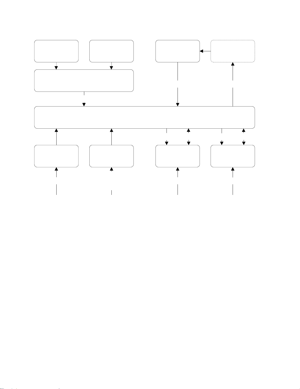
Clock Architecture
Figures 1 and 2 on the following pages provide a simplified view of the standard XL i's clock a rchitectu re.
16.384 MHz Osc. PLL
2
Aux Ref
Aux Ref
1,5,10 MHz
Phase Measurement
1 PPS A
1PPS B
Code Input
DAC
10 MHz Osc.
1 PPS
Timing
Select
Time and Clock
Recovery
Code Input
Clock DPLL
200 MHz PLL
Phase Compare
Clock Machine
Code Generation
1 PPS
Output
Code Out
1
5
1 PPS Out
Code Out
Rate Gen
Rate Out
Rate Out
Figure 1: Functional Timing Block Diagram
XLi IEEE 1588 Clock 7
997-01510-03, Rev. C, 12/12/2006
Page 16
SSSSSSSSSSSS SSSSSSSSSS SSSSSSS S SSS S SSSSS S
1
Display Rb Power
Display/Keypad Interf ace
I/O
Power Supply AC
+5 V, +/- 12 V
110/220 AC
Keypad Oscillator
Backplane Interface
Power
Power Supply
DC +5 V, +/- 12 V
9-18 VDC
18-36 VDC
36-72 VDC
10 MHz
Option
User I/O
I/O
Power
Power, Vc
I/O
T&F CPU
User I/O
Figure 2: Interface Architecture Block Diagram
8 XLi IEEE 1588 Clock
997-01510-03, Rev. C, 12/12/2006
Page 17

SSSSSSSSSSSS SSSSSSSSSS SSSSSSS S SSS S SSSSS S
2: System Specifications
Mechanical/Environmental
Power: 95-260 VAC, 47 to 440 Hz
Operating Temperature: 0 °C to +50 °C (+32 °F to +122 °F)
Maximum Rate of Change: 8 °C per hour
Storage Temperature: -55 °C to +85 °C (-67 °F to +185 °F)
Humidity: To 95% non-condensing
Operating Altitude: Maximum 4 km (2.49 mi. or 13147 ft.)
Front Panel Display: Vacuum Fluorescent Display (VFD) 4.38” x 0.88" (11.13cm x 2.24 cm). 160X16
pixels. Displays startup messages, clock status, time and day of year, and
interactive clock functions. TIME mode displays Time and Day of Y ea r (T OD) on
one full-height line.
Keypad: 0–9, UP, DOWN, LEFT, RIGHT, ENTER, CLR, TIME, STATUS, MENU
Serial I/O: Full user-selectable RS-232/422 communication protocol up to 19200 baud
Vibration Operating: GR-CORE-63, 4.5.2/4, locked to 1.0 g
Storage Transport: GR-CORE-63.4.4.1 to 1.5g
2
1
AC Power Supply
Input:
Input connector: IEC 320 connector
5
Input voltage range: Universal, 90 – 260 VAC and 110 – 370 VDC
Input freq. range: 47 Hz – 440 Hz
Output: +5.2 V (5.0 to 5.4 V), 25 watts, 0 to 5 amps
+12 V (11.4 to 12.6 V), 45 watts, 0 to 3.8 amps
-12 V (-11.4 to -12.6 V) 32 watts, 0 to 2.7 amps
Wattage: 104 watts
Power Supply Status: The Fault Detector monitors all three output voltages and provides a visual
(panel LED) and fault status if any output voltag e decreases by 10%.
Alarm Status LED: Green LED on with no fault and AC power applied. Green LED of f with fault or no
AC power applied.
Fan: Exhaust 3-6 CFM
XLi IEEE 1588 Clock 9
997-01510-03, Rev. C, 12/12/2006
Page 18

SSSSSSSSSSSS SSSSSSSSSS SSSSSSS S SSS S SSSSS S
System Time & Frequency Accuracy
The tables below describe system clock accuracy while locked to the reference source indicated.
Currently, GPS is the only supported reference source.
1
GPS Receiver
1 PPS Output: ±30 ns RMS, 100 ns peak without SA (99%)
Frequency Output Accuracy:
Frequency/Timing, Allan
Deviation, Stability:
< 2x 10
1 x 10
2 x 10
1x 10
-12
-9
@ 1 sec
-10
@ 1000 sec
-12
@ 1 day
AM Code Output Accuracy: 10
DC Level Shift Code Output
Accuracy:
Time to System Lock <20 min. typical
μS to the 1 PPS
200 ns to the 1 PPS
See GPS Signal Strength Requirements (page 17) and GPS C/A Receiver (87-8028-2) (page 4).
Aux Ref Input
If an Aux Ref input is available and enabled, the XLi assumes that Aux Ref is a better frequency source
than its own oscillator. If a timing reference is not available (or becomes unavailable) and Aux Ref is
enabled, the XLi locks to the Aux Ref input. Under those conditions, frequency output accuracy is equal
to the reference < 1 x 10
-12.
Note: To set the time and date manually, see “F3 – Time & Date” on page 40.
Chassis
1U Chassis: Standard 19" EIA Rack System, hardware included
Receiver Size: 1.75 in. x 17.1 in. x 15.35 in.
Weight: Standard configuration, without options ~9.25 lb. Fully loaded ~ 10.95 lb
10 XLi IEEE 1588 Clock
997-01510-03, Rev. C, 12/12/2006
Page 19

SSSSSSSSSSSS SSSSSSSSSS SSSSSSS S SSS S SSSSS S
Standard Inputs and Outputs
The following specifications describe the standard (as opposed to optional) inputs and outputs on the
standard configuration of the XLi.
Serial I/O Port
The standard serial data port is a bi-directional EIA standard RS-232C interface. The serial data port is
configured via the Keypad / Display and Standard network port.
Interface: RS-232 or RS-422
Data Rates: 1200, 2400, 4800, 9600 and 19200 bps
Data Bits: 7 or 8
Parity: even, odd, or none
Stop Bits: 1 or 2
Connector: Male 9-pin D subminiature
Pin Assignment: 1------N/C
2------Rx (RS-232)
3------Tx (RS-232)
4------N/C
5------GND
6------Rx- (RS-422)
7------Rx+ (RS-422)
8------Tx- (RS-422)
9------Tx+ (RS-422)
Factory settings: 9600, 8, N, 1
Note: Parity - NONE is only available/valid when Data Bits is set to 8.
2
1
See “
F4 – Serial Port Configuration” on page 42.
5
NET – Network Port
The Ethernet port interface has a standard RJ-45 connector that provides IEEE 802.3 frame 10/100
Base-T Ethernet. See “
XLi IEEE 1588 Clock 11
997-01510-03, Rev. C, 12/12/2006
F100 – Network Port Configuration & XLi Firmware” on page 80.
Page 20

SSSSSSSSSSSS SSSSSSSSSS SSSSSSS S SSS S SSSSS S
J1 Input – Time Interval - Event Time
The Time Interval - Event Time (TIET) option measures a 1 PPS or Event input signal on J1 against the
XLi derived time. The rising edge of the pulse is measured against XLi time with 5 ns resolution.
1
Pulse Width 100 ns, min.
Active Edge: Rising
Amplitude (DC):
Logic Low: < 1.25V and Min. 300mV
Logic Hi: >1.25V and Max 10V
Impedance: 100 k
Resolution: 5 ns, Single Shot
Accuracy
F110 – J1 Input (TIET)” on page 99.
See “
Ω, 50 Ω
Refer to
“System Time & Frequency Accuracy” on page 10
Note: Any stray input capacitance loading will impact TIET measurements
Note: Configuring J1 as the input for a time code reference source is not supported.
J2 Output – Rate Out
Rate: 1 PPS, 10 PPS, 100 PPS, 1 kPPS, 10 kPPS, 100 kPPS, 1 MPPS, 5
MPPS, 10 MPPS
Duty cycle: 40-60%
Amplitude (TTL): TTL Levels into 50
Quantity: 1
Connector: Female BNC
± 10%
Ω
Factory setting: 10 MPPS
See “F111 – J2 Output (Rate)” on page 102.
Note: Configuring J2 as a Programmable Pulse Output (PPO) is not supported.
12 XLi IEEE 1588 Clock
997-01510-03, Rev. C, 12/12/2006
Page 21

SSSSSSSSSSSS SSSSSSSSSS SSSSSSS S SSS S SSSSS S
J3 Input – Auxiliary Reference
Auxiliary Reference (Aux Ref):
Frequency: 1, 5, 10 MHz
Amplitude: 1 Vp-p to 10 Vp-p at 1 k
Amplitude: 1 Vp-p to 3 Vp-p at 50
Impedance: Configurable 1 k
SNR: >20db
Quantity: 1
Connector: Female BNC
Factory Configuration: Disabled
F113 – J3 Input Configuration (Aux Ref)” on page 104.
See “
Ω or 50 Ω to ground
1 PPS – Pulse Per Second Output
Pulse width: 20
On time edge: Rising
Amplitude: TTL Levels into 50
Quantity: 1
Connector: Female BNC
μS ±1 μS
Ω
Ω to ground
Ω to ground
2
1
If a time reference is unavailable, 1 PPS is as stable as the frequency reference (e.g., OCXO, Aux Ref).
CODE – Time Code Output
5
Format: IRIG-B 000, IRIG-B 120, IRIG-A 003, IRIG-A 133, and NASA 36
Amplitude (AM): 3 Vp-p, into 50
Ratio (AM): 3:1
Amplitude (DC): TTL into 50
Quantity: 1
Connector: Female BNC
Phasing: In phase with carrier
Factory setting: IRIG-B 120
Many IRIG devices only look at the BCD portion of the IRIG frame. Devices that use IRIG A002, B002
and B122 should be able to synchronize with the XLi’s time code outputs.
XLi IEEE 1588 Clock 13
±10%
Ω ±10%
Ω
± 10 μS
997-01510-03, Rev. C, 12/12/2006
Page 22

SSSSSSSSSSSS SSSSSSSSSS SSSSSSS S SSS S SSSSS S
ALARM Output
High Z: Power off
High Z: Alarm (enabled alarm fault)
1
Low Z: Normal (no enabled alarm faults)
Drive: Open Collector
Max. Voltage: 25 VDC
Max. Current: 50 mA
Quantity: 1
Connector: Female BNC
Certifications
UL, C-UL: UL 1950/CSA 22.2 950, Sta ndard for Safety, Information Technology
Equipment (ITE)
FCC: FCC Part 15, Subpart B
CE: 89/336/EEC EMC Directive
73/23/EEC Low Voltage Safety Directive
IEC 60950 Safety of Information Technology Equipment (ITE)
14 XLi IEEE 1588 Clock
997-01510-03, Rev. C, 12/12/2006
Page 23

SSSSSSSSSSSS SSSSSSSSSS SSSSSSS S SSS S SSSSS S
3: Installation and Set-up
In a nutshell:
• Install the GPS antenna outdoors, run the cable, and connect it to the XLi’s GPS receiver.
• Make the following connections to the XLi (all cables supplied):
- From the network to the NET port (for access to the command line and web interfaces).
- From an AC outlet to the XLi’s AC power supply.
• Configure the network settings of the XLi’s standard network port.
• Configure the network settings of the XLi’s IEEE 1588 network port.
Installing the GPS Antenna
Precise Time Protocol (P TP) grandmasters are typically synchronized to International Atomic T ime (TAI).
To accomplish this, the user sets up the GPS antenna, connects it to the GPS receiver in the XLi IEEE
1588 Clock, and configures GPS as its primary reference source. When the XLi IEEE 1588 Clock locks
to the GPS reference source, it computes TAI and synchronizes the PTP grandmaster (the IEEE 1588
card). When the PTP grandmaster is synchronized to the XLi IEEE 1588 clock it starts operating,
sending out PTP Sync and Follow_Up messages and responding to PTP requests.
2
1
Selecting a GPS Antenna Site
Select a site outdoors that...
• Is the highest point available
• Offers a full 360° view horizontally, to within 10° vertically of the horizon
• Is higher than neighboring buildings/obstructions
• Is protected from strong radio frequency (RF) and microwave transmissions
• Is set away from RF-reflective surfaces that cause multipath interference
• Is set 3 ft. (1 m) away from other GPS antennas
• Is within the maximum GPS antenna cable length from the XLi
Typically, this site is on the roof of the building.
Avoid...
• Mounting the antenna between tall buildings or next to walls and equipment
• Exceeding the maximum cable-lengths specified for a particular cabling arrangement.
• Patching multiple cables together to make a single cable run
• Running the cable through bulkheads and along side high-energy cables
• Crimping or damaging the cable
• Mounting within 15 meters/yards of lightning rods, tower, or structures that attract lightning
5
XLi IEEE 1588 Clock 15
997-01510-03, Rev. C, 12/12/2006
Page 24

SSSSSSSSSSSS SSSSSSSSSS SSSSSSS S SSS S SSSSS S
Blocked signals and multipath cancellation significantly increase GPS acquisition time. Multipath
cancellation is caused by reflected signals that reach the antenna out of phase with the direct signal.
Multipath cancellation and blocked signals are typically caused by vertical reflective objects positioned to
the side and above the antenna. To solve these problems, mast mount the antenna at least 1 meter
away from and above the reflecting surface.
1
Verifying the Site
Verify that the length of cable from the GPS antenna site to the XLi does not exceed the maximum GPS
antenna lengths recommended to meet the GPS signal strength requirements. When calculating the
total antenna cable length, include cable that is needed to meet safety and regulatory requirements,
such as lightning arrestors and building code requirements for running coaxial cable from the exterior to
the interior of a building.
If possible, test the GPS signal reception of a particular site before mounting the antenna and running
the cable indoors. Some sites may turn out to be unsuitable due to interference.
Notes:
• The XLi requires a 12-volt compatible antenna. Antennas not rated for 12 V will be damaged.
• Use a splitter, not a BNC “T” connector, when connecting an antenna to multiple receivers.
• The L1 GPS antenna is designed to operate with up to 150 ft. (45.72 m) of RG-59 coax cable.
•A line amplifier is available for cable runs between 150 - 300 ft. (46 - 91 m) in length (RG-59).
•A down-converter kit is available for cable runs of 1,500 ft. (457.2 m) in length (RG-58).
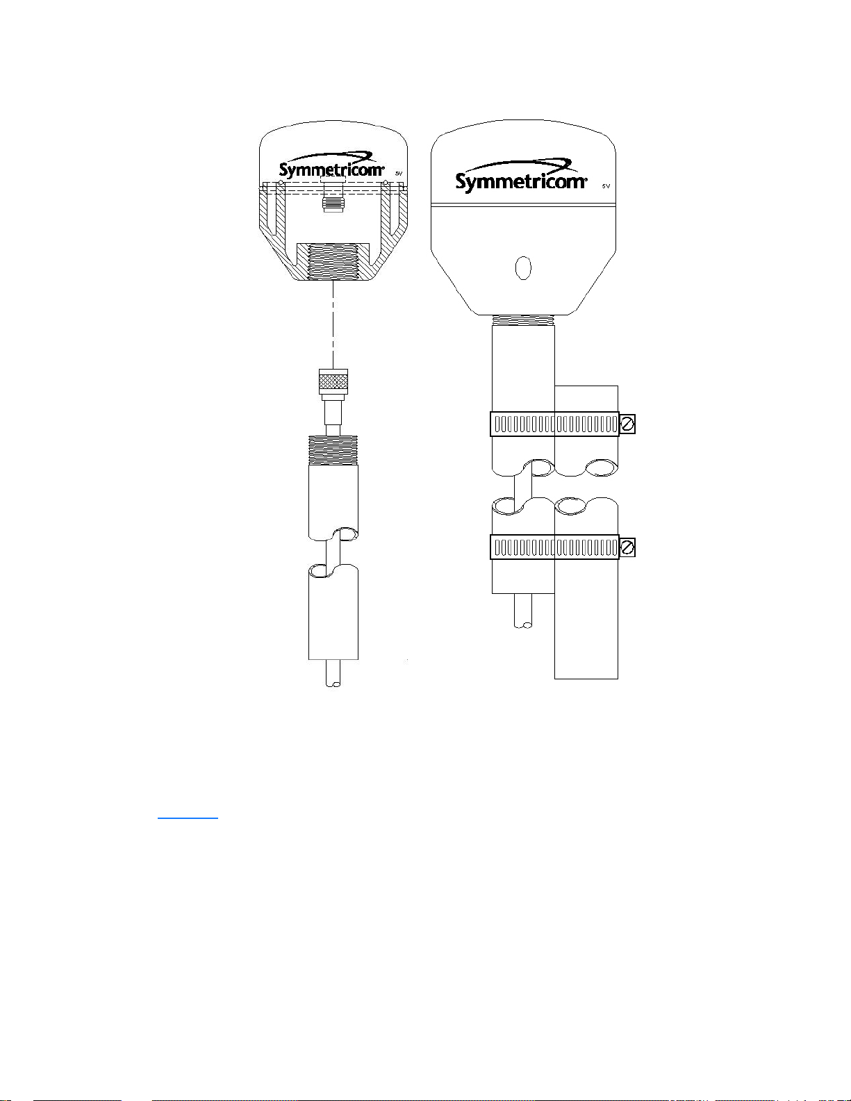
Mounting the GPS Antenna
Mount the GPS antenna on an antenna mast (recommended) or on the peak of a building. For the mast,
use 2-inch (5.08-cm) diameter PVC pipe or conduit that is rigid enough to withstand high winds without
flexing. Use guy wires to stabilize masts longer than 10 ft. (3.048 m). Avoid mounting the antenna on a
tower, which requires a specialist to maintain.
16 XLi IEEE 1588 Clock
997-01510-03, Rev. C, 12/12/2006
Page 25
SSSSSSSSSSSS SSSSSSSSSS SSSSSSS S SSS S SSSSS S
2
1
5
Figure 3: L1 GPS Antenna - methods for cabling and mounting
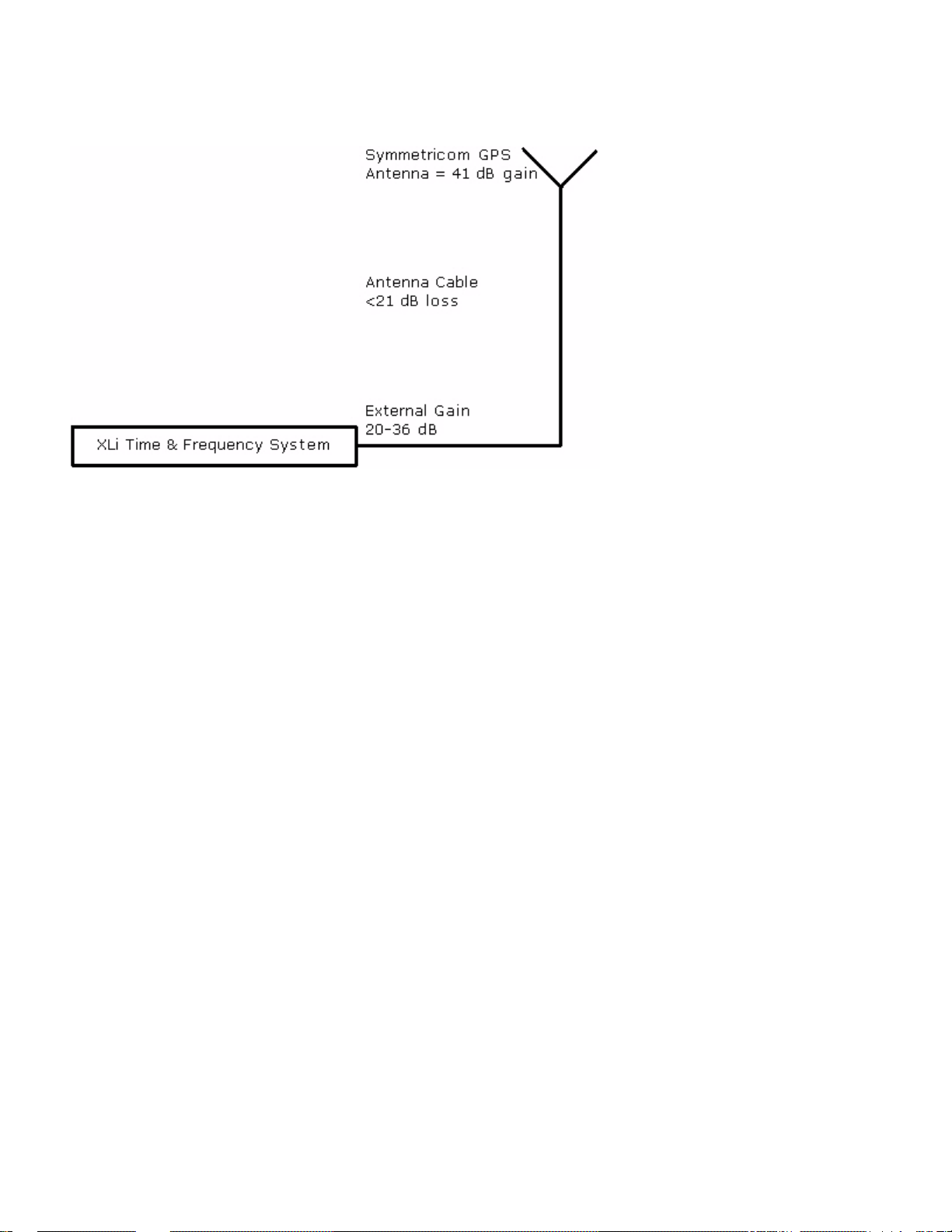
GPS Signal Strength Requirements
Refer to Figure 4:The required gain at the GPS receiver’s ANTENNA connector is greater than 20 dB
and less than 36 dB. A 150 foot length of RG-59 coax cable of has a loss of 16-21 dB, which meets this
requirement. Abide by the minimum input gain requirements if using other cable types. Additionally, if
changing the antenna, abide by the 41 dB gain requirement. Other factors, such as radiation, coverage ,
XLi IEEE 1588 Clock 17
997-01510-03, Rev. C, 12/12/2006
Page 26
SSSSSSSSSSSS SSSSSSSSSS SSSSSSS S SSS S SSSSS S
VSWR, and input impedance also affect system performance. Symmetricom recommends using the
standard 12-volt capable antenna and cable provided with the GPS receiver.
1
Figure 4: GPS Signal Strength Requirements
Connect the GPS antenna cable to the GPS receiver’s ANTENNA connector at the rear of the XLi.
Note: Use a 12-volt capable GPS antenna.
Making Additional Connections and Powering Up
Make the following connections to the XLi (all cables supplied):
1. For access to the web and command line interfaces, connect NET network po rt (on the Main CPU
Card, 87-8000) to the LAN using the Cat 5 network cable (supplied).
For local access to the command line interface only, connect the SERIAL I/O port (on the Main CPU
Card, 87-8000) to the to the PC’s serial port using a null modem cable.
2. Connect the 1588 network port to the timing network.
3. Connect the AC Power Supply it to a power source. The green STATUS light on the power supply
indicates that the XLi is receiving power.
Upon receiving power, the XLi goes through its startup sequence; displaying “BOOTING”, “LOADING”, and “ST ARTING”. After approxima tely 40 seconds, the XLi displays the clock status, and user
interfaces (front panel/command line) become available. The IEEE 1588 card requires an additional
2 minutes to complete its startup sequence before it is available from the user interfaces.
Warning: Ensure that a disconnect device, such as a switch, with the appropriate voltage/
current rating is provided when operating/installing the XLi.
18 XLi IEEE 1588 Clock
997-01510-03, Rev. C, 12/12/2006
Page 27

SSSSSSSSSSSS SSSSSSSSSS SSSSSSS S SSS S SSSSS S
Configuring Network Settings
The following steps are required to make the XLi’s Main CPU card operational on a network. Do this if
you plan on using the command line or web interface to manage the XLi over the network.
Using the front panel keypad/display configure the network port settings as follows:
Press Result
ENTER Displays “FUNCTION”
100 Enters 100 as the function number
2
ENTER Displays Function 100’s first screen: “
ENTER Displays “
1-9… Enter the unit’s IP Address (e.g., 192.168.0.11
ENTER Displays “
1-9… Enter the Subnet Mask (e.g., 255.255.255.000)
ENTER Displays “
1-9… Enter the Default Gateway’s IP address (e.g., 192.168.0.1)
ENTER Displays “
ENTER Displays “
ENTER (5 times) Displays “
ENTER Saves the new network parameters, and reboots the XLi
IP ADDRESS…”
SUBNET MASK…”
DEFAULT GATEWAY…”
10-100 BASE-T (CURR BW 10) - AUTO”
REMOTE LOCKOUT – UNLOCK” (Leave unchanged)
SAVE CHANGES – YES”
COMPANY 00-A0-69…”
1
Configuring the XLi
Enter the XLi’s IP address as the address in a browser and log on to the XLi’ s web interface. The factory
set user name is “operator1” and the password is “zeus”. If this XLi was field-upgraded for IEEE 1588
operation, the password may also be “casey”.
5
• Click the Admin Home link and then the Accounts Admin link. Change the factory set user
names and passwords.
• Click the Admin Home link and then the Option Bay # GPS M12 RECEIVER link.
- Verify that the Antenna Cable Delay is correct. For the standard 50 foot (15.24 m) coaxial
cable supplied with the GPS antenna, the Antenna Cable Delay is 60 ns. To compute the correct value for other antenna cable lengths, see “
page 55.
- Leave GPS Operation Mode as “Dynamic” and Time Reference as “Primary”.
• Click the GPS Config & Status link. After approximately 20 minutes of operation, check that
GPS Clock Status is locked and GPS Antenna is OK.
- If GPS Antenna is OK and GPS Clock Status is unlocked, click the GPS Satellite List link.
The Tracked Satellite List should list four or more “current” GPS satellites. It may take significantly longer than 20 minutes for four or more “current” GPS satellites to appear if the GPS
XLi IEEE 1588 Clock 19
997-01510-03, Rev. C, 12/12/2006
F51 – GPS Antenna Cable Delay” on
Page 28

SSSSSSSSSSSS SSSSSSSSSS SSSSSSS S SSS S SSSSS S
antenna is not in an optimal site or there is a problem with the antenna cable connections. If
this delay is unexpected, consider relocating the GPS antenna to a better site or troubleshooting the GPS antenna cable.
• Press the ST ATUS key on the front panel. The display shou ld show “LOCKED GPS PRI” without
1
an asterisk (“*”). If an asterisk appears, it means that the GPS receiver is currently unlocked
from the GPS satellites, this may indicate a problem with GPS satellite visibility or signal strength.
Configuring the IEEE 1588 Card(s)
Two versions of the XLi IEEE 1588 clock are currently available:
The first version has:
• An IEEE 1588 card configured as a PTP master in Option Bay 4
• A GPS receiver in Option Bay 1
The second version has:
• An IEEE 1588 card configured as a PTP master in Option Bay 4
• An IEEE 1588 card configured as a PTP slave in Option Bay 2
• A GPS receiver in Option Bay 1
Note: With two IEEE cards, be mindful of the Option Bay number when changing the settings.
PTP Master
Note: The IEEE 1588 card requires 5 minutes from power up to initialize. Until then, the card does not
appear in the user interfaces, or is reported as "NOT AVAILABLE".
Function F131 is available for configuring IEEE 1588 cards. The IEEE 1588 card located in Option Bay 4
is preconfigured as a PTP master, as shown here:
• PTP AVAILABILITY - OPTION BAY 4
• PTP IP ADDRESS (STATIC) - 010.048.000.103
• PTP SUBNET MASK (STATIC) - 255.255.000.000
• PTP DEFAULT GATEWAY (STATIC) - 010.024.000.001
• PTP DHCP - ENABLE
• PTP SYNC INTERVAL - 2 SECONDS
• PTP BURST MODE - DISABLE
• PTP PORT STATE - ENABLE
• PTP SUBDOMAIN NAME - _DFLT
• PTP RESET TO FACTORY DFLT? - NO
• PTP INIT TO USER SETTINGS? - NO
• PTP CLOCK CONFIG, BAY 1 - MASTER
20 XLi IEEE 1588 Clock
997-01510-03, Rev. C, 12/12/2006
Page 29

SSSSSSSSSSSS SSSSSSSSSS SSSSSSS S SSS S SSSSS S
• SLAVE SYNC THRESHOLD - 5 microsec
• PTP PREFERRED MASTER - DISABLE
Note: When two IEEE 1588 cards are present, use the up/down arrow keys to select the PTP master in
Option Bay 4 before making changes.
Using the familiar keypad display interface, modify the following F131 settings:
• If a DHCP server is not available on the timing network, disable DHCP and set static values for
the PTP IP ADDRES, SUBNET MASK, and DEFAULT GATEWAY.
• Configure the following settings on so that the PTP master and PTP slaves match each other:
- PTP SYNC INTERVAL - The rate at which synchronization packets are sent out. The factory
setting, 2 seconds, is the recommended value.
- PTP BURST MODE - Enables quick and accurate synchronization. Generates additional net-
work traffic.
- PTP SUBDOMAIN - Defines the PTP master as a member of a logical timing network.
• (Recommended) Enable PTP PREFERRED MASTER to have P TP slaves on the timing network
favor the PTP grandmaster over other potential masters.
1
2
1
IMPORTANT: If one of the PTP slaves on the timing network is a Symmetricom IEEE 1588 card,
the interval for all PTP masters and PTP slaves must be set to 2 SECONDS.
PTP Slave
To reconfigure the IEEE 1588 card from being a PTP master to being a PTP slave, complete the
following steps:
1. Having logged in to the web interface, from the Admin Homepage, click the link Option Bay 4 IEEE
1588 Master. The new 1588 web page takes approximately 5 seconds to load.
2. Set Clock Configuration to Slave Primary.
5
3. Try operating with Slave Synchronization Threshold at 5 microseconds. Timing networks with bursty
or heavy traffic, routers, or many layers of hubs and switches may nee d the hig her 1000 microsecond setting.
4. Click the Submit Changes button.
5. The front panel display should show "LOCKED PTP PRI" soon after.
The IEEE 1588 card is now operating as a PTP slave and is also functioning as the primary reference
source to the PTP master. The GPS receiver, which was previously operating as the primary reference
source to the IEEE 1588 clock, is now a STANDBY reference source.
1. After saving changes, if DHCP is enabled and a DHCP server is available, F131 displays the DHCP-assigned settings following the PTP DHCP ENABLE screen.
XLi IEEE 1588 Clock 21
997-01510-03, Rev. C, 12/12/2006
Page 30
SSSSSSSSSSSS SSSSSSSSSS SSSSSSS S SSS S SSSSS S
Note: The IEEE 1588 card configured as a PTP slave relies on TAI as the time scale of the PTP master.
Distributing non-TAI time over PTP while the PTP slave is a reference source will have a predictable effect on the XLi’s system time.
Note: Later on, when reconfiguring the IEEE 1588 card as a PTP master, use F119 to set the GPS
1
receiver as the PRIMARY reference source. (In F119: Set GPS TIME REFERENCE, BAY 1 to
PRIMARY.)
Note: For XLi IEEE 1588 Clocks with the second IEEE 1588 card in Option Bay 2 (preconfigured a PTP
slave, configure the network settings, PTP SYNC INTERVAL, PTP BURST MODE, and PTP
SUBDOMAIN. The factory settings are the same as for the PTP master, except the static IP
Address is 010.048.000.105 and Clock Configuration is Slave Primary.
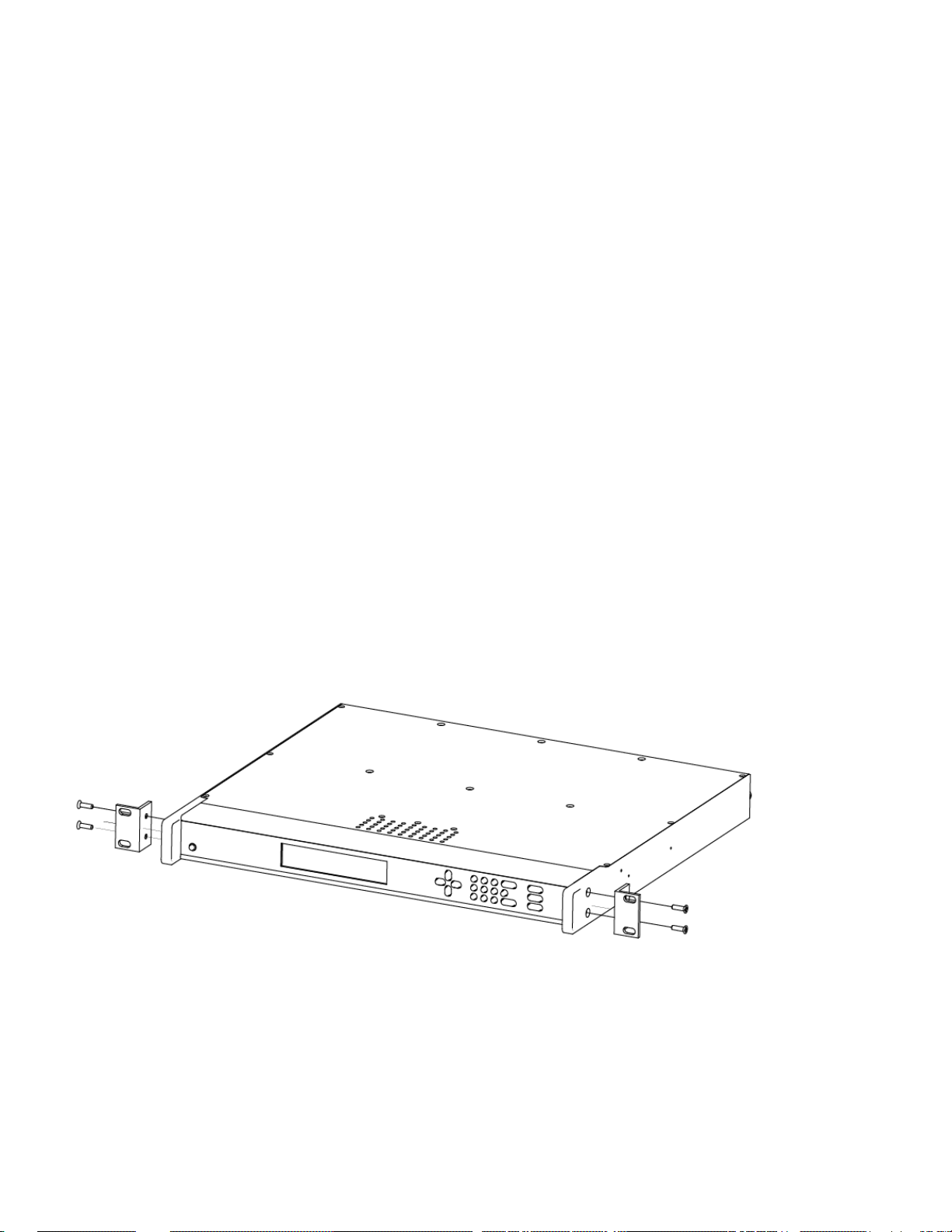
Rack Mounting the XLi
The XLi comes with the following parts needed to mount the XLi securely in any EIA standard 19-inch
(48.26-cm) rack:
• 2 mounting brackets
• 4 flat-head, Phillips screws
Have the following items ready and available:
• The appropriate AC source to connect to the XLi’s power supply.
• A #2 size Phillips bit screwdriver
To rack mount the XLi:
• Unscrew the four phillips-head screws from the front end of the side panels.
• Use the same screws to attach the rack mount brackets, as shown.
• Tighten the screws using a #2 size Phillips screwdriver.
• Position the XLi in any EIA Standard 19-inch (48.26 cm) rack system, and line up holes in the
brackets with the holes in the rack.
22 XLi IEEE 1588 Clock
997-01510-03, Rev. C, 12/12/2006
Page 31

SSSSSSSSSSSS SSSSSSSSSS SSSSSSS S SSS S SSSSS S
• Secure the brackets to the rack using rack mount screws.
2
Note: Ensure that the ambient operating temperature does not exceed +50° C. Install the XLi chassis so
that the top and bottom holes are unobstructed and have suf ficient clearance to allow 6 cfm of air
to pass through the chassis. To maintain recommended operating temperatures, install a rackcooling fan capable of 100 cfm in heavily loaded racks.
1
5
XLi IEEE 1588 Clock 23
997-01510-03, Rev. C, 12/12/2006
Page 32

SSSSSSSSSSSS SSSSSSSSSS SSSSSSS S SSS S SSSSS S
1
24 XLi IEEE 1588 Clock
997-01510-03, Rev. C, 12/12/2006
Page 33

SSSSSSSSSSSS SSSSSSSSSS SSSSSSS S SSS S SSSSS S
4: User Interfaces
The XLi features two user interfaces for controlling the XLi’s functions:
• A keypad/display interface
• A command line interface
• A web interface
There is also an Alarm Status LED
, available from a browser connected to the XLi’s network port.
on the front panel of the XLi
, available through the serial and network ports
on the front panel.
2
Alarm Status LED
The Alarm Status LED, located on the front panel, displays the alarm-state of the XLi unit. The LED has
four states:
Dark
Green
Amber
Red
Notes:
= Power is off.
= No F73-related alarms. The current reference source input is locked.
= No F73 Alarms. Ti meout Delay is counting down, but hasn’t elapsed. The current reference
source input is unlocked (e.g. broken antenna cable or no GPS signal)
= An indicator in F73 has triggered an alarm. Check F73 to find out what the fault/unlock condition
is and take appropriate action.
• The amber LED can turn green again while the reference source input remains unlocked
because:
- F119’s ‘GPS Status’ controls whether
- F73’s ‘Timeout Delay’ controls how long
• The blinking of the LED has no meaning. It is a user preference that can be enabled or disabled
using the F73’s ‘LED Blink’ setting. If enabled, the LED blinks when it is green and yellow, but
stays unblinking when it is red. If disabled, the LED doesn’t blink.
the LED turns amber.
the LED remains amber.
1
5
Keypad/Display Interface
Time Display
Press the TIME button on the keypad to display the time only. Use the TIME button to exit the STATUS,
MENU, or function displays. The time format is DDD:HH:MM:SS.
200:21:24:09
XLi IEEE 1588 Clock 25
997-01510-03, Rev. C, 12/12/2006
Page 34

SSSSSSSSSSSS SSSSSSSSSS SSSSSSS S SSS S SSSSS S
Time Display related functions:
• Select between the 12 or 24 hour format displayed: “
Time related functions:
1
F1 – Time Zone Offset” on page 38
• “
F2 – 12/24 Hour Format” on page 39.
• “F3 – Time & Date” on page 40
• “F66 – Daylight Saving Time (DST) Mode” on page 63
Status Display
The Status Display comes up automatically when the XLi is rebooted. To manually switch from another
display to the Status Display, press STATUS button on the keypad. The keypad appears as follows:
LOCKED ∗ GPS PRI
UTC 200:21:24:09 2002
where:
LOCKED = System Clock Status is Locked or Unlocked to the current reference source. See Clock
Status in
“F73 – Alarm Control / Status” on page 69
* = A reference source input has been configured, but is not available. (Note: When using
GPS, “*” may remain visible for up to 13 minutes) See
“F119 – GPS Receiver
Configuration” on page 110
GPS PRI = Shows the reference source type (The function that controls each one is noted below):
• GPS PRI, GPS SEC (
• PTP PRI, PTP SEC (“F131 - Precision Time Protocol Network Config” on
“F119 – GPS Receiver Configuration” on page 110)
page 119)
The “IRIG” and “AUX REF” reference sources are also possible, but not supported.
Automatic switching between the reference sources listed above is controlled by
“F74 –
Clock Source Control” on page 77.
UTC =
Time display mode: GPS, UTC, TAI, Standard, or Local (
“F69 – Time Mode” on
page 65)
200:21:24:09 2002 =
The time, in DDD:HH:MM:SS YYYY format (
See “Time Display” on page 25.)
Menu Display
To use the XLi functions that are available from the keypad, press the MENU button on the keypad.
Function Summary” on page 35 lists which functions are available from the Menu Display.
“
26 XLi IEEE 1588 Clock
997-01510-03, Rev. C, 12/12/2006
Page 35

SSSSSSSSSSSS SSSSSSSSSS SSSSSSS S SSS S SSSSS S
Pressing the MENU key on the front of the XLi displays the first function, F1: TIME ZONE OFFSET:
F1:
TIME ZONE OFFSET
Pressing the UP ARROW key increments to the next function, F2 - 12/24 HOUR FORMAT, and so on.
Pressing the DOWN ARROW key skips to the highest available function, F126 OPTIONS KEY ENTRY,
and, from there, decrements through the functions.
2
The section, “
functions.
Keypad Operation
Use XLi’s front panel keypad to operate the menu-driven keypad/display interface.
5: Function Reference” on page 35, provides detailed information on all of the XLi’s
1
The following table explains how the individual keys work:
UP ARROW Increase value/Display next choice above
DOWN ARROW Decrease value/Display next choice below
RIGHT ARROW Move cursor right
LEFT ARROW Move cursor left
0-9 Enter numeric values
ENTER Enters currently displayed choice, e.g., a function or yes/confirmatio n to save changes
CLR Clears the current selection/choice and returns to the last saved value
TIME Displays the current time. Can also be used to exit a function without saving changes.
STATUS Displays the clock status and time. Can be used to exit a function without saving
changes.
MENU Displays first item in function menu. Use UP/DOWN ARROWs to display other functions.
5
XLi IEEE 1588 Clock 27
997-01510-03, Rev. C, 12/12/2006
Page 36

SSSSSSSSSSSS SSSSSSSSSS SSSSSSS S SSS S SSSSS S
Keypad Examples
The following examples show how to use the keypad effectively.
To open a function using ENTER:
1
Press Result
ENTER Displays the “FUNCTION” prompt
2 Enter the function’s number (“2” in this example)
ENTER Displays F2’s first screen, “
DISPLAY HOUR FORMAT: 24 HOUR”
To open a function using MENU:
Press Result
MENU Displays F1 on the front panel display
UP/DOWN ARROW Scrolls through the list of functions
ENTER Opens the function and displays its first screen
To change the settings in a function, and not save them:
Press Result
MENU Displays “F1: TIME ZONE OFFSET”
ENTER Displays “
UP ARROW Changes the minus sign in “
RIGHT ARROW Moves the cursor to the right, under “
UP ARROW Changes “
TIME ZONE OFFSET –08:00”
– 08:00” to a plus in “+08:00”
0”.
0” to “1”, making “+18:00”
ENTER XLi asks “
UP ARROW Changes “
ENTER Abandons the changes and displays the Status Display
SAVE CHANGES? YES”
YES” to “NO”
Other ways to abandon new settings in a function:
Press Result
CLR Abandons all changes and displays to the first screen in the function
TIME Abandons all changes, exits the function, and displays the Time Display
STATUS Abandons all changes, exits the function, and displays the Status Display
28 XLi IEEE 1588 Clock
997-01510-03, Rev. C, 12/12/2006
Page 37

SSSSSSSSSSSS SSSSSSSSSS SSSSSSS S SSS S SSSSS S
To enter numeric values in a function:
Press Result
ENTER Displays the “FUNCTION” prompt
3 Enters “
ENTER Opens Function 3, displays the first screen, “
ENTER Displays the second parameter, “
05152002 Enters May 15, 2002 as today’s date. (replace)
ENTER Displays “
ENTER XLi asks “
ENTER Selects “
Command Line Interface
To open a command line session, connect to the serial or network port using a terminal or a terminal
emulation program on a PC.
Consult “
5: Function Reference” on page 35 for information on the function commands.
3” as the function number
TIME MODE – LOCAL”
DATE-TIME…<mm>/<dd>/<yyyy>”
DATE-TIME”
SAVE CHANGES? YES”
YES”, saves the changes, and displays the Status Display
2
1
Logging In
Two u ser names are available for logging in to the network po rt’s command line interface: “operator” an d
“guest”. The serial port’s command line interface does not require the user to log in.
Operator Login
The Operator has full privileges to change the settings in all the XLi’s functions and to perform firmware
updates. As shipped, you can log in as Operator using:
User Name: operator
Password: janus
To maintain security, change the Operator password at installatio n. If you are logged in as “operator”, the
only command line interface function you cannot perform is changing the Guest password.
Guest Login
Use the guest login to view function settings. As shipped, you can log in as guest using:
User Name: guest
Password: ttm
To maintain security, change the Guest password at installation. If you try to use a function that is not
accessible from the guest login, you will see a message such as “Access denied” or “Command
canceled”.
XLi IEEE 1588 Clock 29
5
997-01510-03, Rev. C, 12/12/2006
Page 38

SSSSSSSSSSSS SSSSSSSSSS SSSSSSS S SSS S SSSSS S
Logging Out
You can log out using any of the following commands:
logout
1
logoff
exit
quit
Changing Username and Password
To change the user name and password, use the following commands:
• “
F100 P – Change User Password” on page 95
• “F100 PN – Change User Name” on page 97
To reset a lost or forgotten operator username/password , use F100 P and F100 PN comma nds from the
command line interface on the serial port.
Session Timeout and Priority
The XLi’s system firmware closes inactive command line sessions on the network port after 15 minutes.
The XLi does not terminate inactive command line sessions on the serial port.
The user can open a network port session and a serial ports session concurrently, provided the other
session is inactive
(i.e., not actively performing a function such as F8 - Continuous Time Once-per-
Second). The XLi does not allow two or more concurrent network port sessions.
A network port session can be active while an inactive serial port session is open. However, if the serial
port session receives user input at this point, it takes control away from the network port and does not
yield control to the network port again. The network port will show a prompt, but won’t accept additional
commands after the serial port has taken control. Attempting to close the network port session and open
a new one will fail; a network port connection cannot be re-established until the serial port has been
closed. The following transcripts shows a ‘contest’ between a serial and a network port session:
Serial port session:
>f100 ic
f100 IP:192.168.46.150 SM:255.255.255.0 G:192.168.46. 1
>NOTICE: A NEW TELNET SESSION HAS BEEN STARTED ON THE INTERNET POR T!
>f100 ic
NOTICE: THERE IS ALREADY A TELNET SESSION ON THE INTE RNET PORT!
NOTICE: YOU HAVE TAKEN CONTROL AWAY FROM THE TELNET S ESSION!
f100 IP:192.168.46.150 SM:255.255.255.0 G:192.168.46. 1
>f100 ic
f100 IP:192.168.46.150 SM:255.255.255.0 G:192.168.46. 1
>
30 XLi IEEE 1588 Clock
997-01510-03, Rev. C, 12/12/2006
Page 39

SSSSSSSSSSSS SSSSSSSSSS SSSSSSS S SSS S SSSSS S
Network port session:
WELCOME TO SYMMETRICOM NETWORK INTERFACE!
USER NAME: operator
PASSWORD: *****
NETWORK INTERFACE 192-8001 (c) 1998 - 2003 SYMME TRICOM
ALL RIGHTS RESERVED
LOGIN SUCCESSFUL!
>f100 ic
f100 IP:192.168.46.150 SM:255.255.255.0 G:192.168.46. 1
2
>NOTICE: UTILITY MONITOR SESSION HAS TAKEN PRIORITY F ROM THIS TELNE T SESSION!
>f100 ic
NOTICE: CANNOT RESPOND TO COMMAND BECAUSE UTILITY POR T SESSION HAS PRIORITY!
Web Interface
The web interface makes most of the XLi’s functions conveniently accessible using a browser.
1
5
Figure 5. The web interface showing the XLi Admin Homepage
User Privileges
Administrative users can view status information and change the XLi’ s configuration. Non-administrative
users can view status information, but cannot change the XLi’s configuration.
XLi IEEE 1588 Clock 31
997-01510-03, Rev. C, 12/12/2006
Page 40

SSSSSSSSSSSS SSSSSSSSSS SSSSSSS S SSS S SSSSS S
The web interface manages this distinction by providing two sets of web pages. Pages available from the
XLi Admin Homepage display status information and let the user change the XLi’s configuration settings.
Pages available from the XLi User Homepage only display status information.
Administrative users (e.g., operator1) have access to both the XLi Admin Homepage and the XLi User
1
Homepage sets of pages. Non-administrative users (e.g., user1) only have access to the XLi User
Homepage set of pages.
Sessions
Only one user can be logged into the web interface at a time. The web interface does not support
concurrent web sessions. If a second user tries to log in, the browser displays a "503 Web Page Server
Busy" message.
The XLi supports concurrent user sessions on the web and command line interfaces (on the network or
serial port). However, Symmetricom recommends avoiding concurrent administrative user sessions.
The XLi’s web server automatically closes inactive web sessions after 30 minutes of inactivity.
User Names and Passwords
The ten administrative user names, “operator1” through “operator10”, have “zeus” as the factory set
password.
The ten non-administrative user names, “user1” through “user10”, have “ttm” as the factory set
password.
Only administrative users can change the user names and passwords. User names and p asswords must
have 1 to 15 characters, and are limited to upper/lower case alphanumeric and underscore (“_”)
characters. No “special” characters.
Logging In
To log in, enter the IP address of the XLi’s “NET” network port into the web browser’s address field. At
the XLi Home Page, click the Login button. Enter the appro priate user name and p assword and click the
Login button with your mouse. The browser displays the XLi Admin Homepage or XLi User Homepage.
Navigating
Several notes about using the web interface:
• The home page presents an image of the XLi’ s front p anel to assist with ident ification, should the
user need to find it on a rack.
• The images of the 1U chassis show the position of the options bays as seen from t he rear of the
unit.
The links on the left navigation bar provide access to three different aspects of the XLi:
• General - the general status and configuration of the XLi system (e.g., user accounts, clock
32 XLi IEEE 1588 Clock
997-01510-03, Rev. C, 12/12/2006
Page 41

SSSSSSSSSSSS SSSSSSSSSS SSSSSSS S SSS S SSSSS S
settings, alarms, and SNMP).
• System I/O - the status and configuration of the input and output connectors on the rear of the
main CPU card (e.g., communication settings, code out, J1, J2, and J3).
• Subsystem - configuration of the option cards located in the option bays
Under Subsystem, the XLi names CPU-aware option cards to the right of the option bay where they are
located. Non-CPU aware cards can be present and fully operational in an option bay, but are not shown
in the web interface. For more information, see F118 – Option Board Configuration
Only option bays with CPU-aware option cards will have active links. Clicking the link of an unpopulated
or non-existent option bay simply refreshes the web page.
When clicking on links, allow each page to load before clicking another link. Clicking links too quickly
may cause the Login page to appear.
(page 108).
2
Submitting Changes
When submitting changes, only click the Submit Changes button once. Wait for the web page to load
before navigating away from the page or submitting another change.
1
Logging Out
To log out, click the Logout button located in the upper left corner of the page.
If the user closes the browser without logging out, a new session will not be available until the XLi closes
the inactive session after 30 minutes.
Notes
Notes for specific pages in the web interface:
• Units equipped with the GPS C/A Receiver (87-8028-2): When the user changes the M12 GPS
Mode setting and applies the changes, the GPS C/A Receiver goes through several states
before attaining the user-specified mode.
• Change Login Page: To change the Operator name, but not the password, leave the password
field blank and submit the change.
• The NTP option, though mentioned in the Web Interface, is currently unavailable for the st andard
XLi IEEE 1588 clock.
5
XLi IEEE 1588 Clock 33
997-01510-03, Rev. C, 12/12/2006
Page 42

SSSSSSSSSSSS SSSSSSSSSS SSSSSSS S SSS S SSSSS S
1
34 XLi IEEE 1588 Clock
997-01510-03, Rev. C, 12/12/2006
Page 43

SSSSSSSSSSSS SSSSSSSSSS SSSSSSS S SSS S SSSSS S
5: Function Reference
Function Summary
The following summary lists all the XLi functions, identifies the user interfaces from which each one is
available, and provides a brief description of the function.
Available from: K = keypad, N = Network Port (Telnet), S = Serial Port, W = Web
Function
F1 – Time Zone Offset
F2 – 12/24 Hour Format
F3 – Time & Date
F4 – Serial Port Configuration
F5 – Time-Quality Setup
F6 – Keypad Lock
F8 - Continuous Time Once-perSecond
F9 - Time On Request
F11 - Time Output Format
F13 – Time Error
F18 – Software Version Request
Available
From
K,N,S,W Set the time offset for Standard and Local time
K,N,S,W Apply a 12 or 24-hour format to the Front Panel Display, to
K,N,S,W Set the time and date (when not already provided by a
K,N,W Configure the main serial port settings
K,N,S,W Set the thresholds for each of the four time quality flags
K*,N,S Lock keypad access to the XLi’s functions. (When locked,
N,S Output the time once -per-second (to the command line)
N,S Output the time when triggere d (to the command line)
N,S Change the format of the time output by F8 and F9
K,N,S,W View the current estimated worst case time error
K,N,S,W View the XLi’s software version information
Description
F8, F9, and F90.
reference source)
F6 is the only function available from the keypad.)
2
1
5
F27 – FTM III Configuration
F42 – Multicode Output Configuration K,N,S,W Not supported.
F44 – N.8 Frequency Synthesizer
F50 – GPS Receiver LLA/XYZ Position
F51 – GPS Antenna Cable Delay
F52 – Distribution Cable Delay
F53 – GPS Operation Mode
F60 – GPS Receiver Satellite List
XLi IEEE 1588 Clock 35
997-01510-03, Rev. C, 12/12/2006
K,N,S,W Not supported.
K,N,S,W Not supported.
K,N,S,W View the Latitude/Longitude/Altitude or geocentric X/Y/Z
coordinates of one or more GPS antennas.
K,N,S,W Compensate for the delay caused by the length of the GPS
antenna cable. (Use F52 to adjust timing
K,N,S,W Compensate for the length of the distribution cable on J2.
K,N,S,W Operate specific GPS receivers in Time Mode for static
applications, or in Dynamic Mode for mobile applications.
K,N,S,W View a list of current and tracked satellites.
outputs.)
Page 44

SSSSSSSSSSSS SSSSSSSSSS SSSSSSS S SSS S SSSSS S
F66 – Daylight Saving Time (DST)
Mode
F69 – Time Mode
1
F71 – Oscillator Statistics
F72 – Fault Status
F73 – Alarm Control / Status
F74 – Clock Source Control
F90 – Code Output Configuration
F100 – Network Port Configuration &
XLi Firmware
F100 EA – Ethernet Address
F100 IP – IP Address
F100 SM – Subnet Mask
K,N,S,W Schedule when DST starts and ends (Local time only)
K,N,S,W Set the time scale (T AI, GPS, UTC, S t andard, Local) output
by the IEEE 1588 card and displayed on the front panel of
the XLi. (TAI is the recommended setting).
K,N,S,W Display the XLi oscillator’s phase, offset, drift, and DAC
values
K,N,S,W View clock and power supply faul t status
K,N,S,W View the status of all the alarm indicators. Enable/disable
alarms for each indicator. Set alarm thresholds. Enable or
disable LED blink
K,N,S,W Select the pattern of switching between reference sources
K,N,S,W Configure settings for CODE – time code output
K,N,S,W Configure the standard network port se ttings
K,N,S,W Display the Ethernet (MAC) address
K,N,S,W Configure the IP address
K,N,S,W Configure the subnet mask
F100 G – Gateway
F100 IC – Network Port Settings
F100 L/LOCK/UNLOCK – Remote
Lockout
F100 L – Remote Lockout
F100 ST – Self Test Status
F100 BH – Burn Host
F100 BUB – Burn BootLoader
F100 BU – Burn
F100 BF – Burn File System
F100 BUFP – Burn FPGA Firmware
F100 CONFIG – Configure NTP &
SNMP
K,N,S,W Configure the default gateway
K,N,S,W Display all the standard network port’s settings
K,N,S Lock remote access to the XLi’s standard network port
K,N*,S Display the status of F100 LOCK
*Locked through the network port, serial port, and keypad.
Can be unlocked only through the keypad or serial port.
K,N,S Display the XLi’s self test results for Flash CRC, RAM,
Serial Port, and NVRAM
N,S Upgrading system firmware: select the FTP host, path, and
filename of the system firmware
N,S Upgrading system firm wa re : ‘bur n’ the boo tloader file (* .b t)
selected using F100 BH to flash memory
N,S Upgrading system firmware: ‘b urn’ the system fir mware file
(*.bin) selected using F100 BH to flash memory
N,S Upgrading system firmware: ‘burn’ the file system file (*.fs)
selected using F100 BH to flash memory
N,S Upgrading system firmware: burn the FPGA program file
(*.bin) selected using F100 BH to the flash memory
a
N,S,W*
Transfer the SNMP configuration file between the XLi and
an FTP server for editing
F100 J – Factory Mode Jumper
36 XLi IEEE 1588 Clock
N,S View the status of the factory mode jumper, which is used
by factory technicians. Not of interest to most end users.
997-01510-03, Rev. C, 12/12/2006
Page 45

SSSSSSSSSSSS SSSSSSSSSS SSSSSSS S SSS S SSSSS S
F100 K I L L – Reboot
F100 P – Change User Password
F100 PI – PING
F100 PN – Change User Name
F108 – Oscillator Configuration
F110 – J1 Input (TIET)
F111 – J2 Output (Rate)
F113 – J3 Input Configuration (Aux
Ref)
F116 – Display Brightness Level
F117 – Factory Configuration
F118 – Option Board Configuration
F119 – GPS Receiver Configuration
F120 - N.1 Frequency Synthesizer
N,S Reboot the XLi
N,S,W Change the XLi password
N,S Ping from the XLi to another host on the network
N,S,W Change the User Name
K,N,S,W View the oscillator type
K,N,S,W Configure the J1 input connector. IRIG Time Code not
supported.
K,N,S,W Configure the J2 output connector. PPO not supported.
K,N,S,W Configure the J3 input connector. Freq Meas not
supported.
K Set the brightness of the display on the XLi’s front panel
K,N,S,W View some of the factory settings such as the serial
number
K,N,S,W View the contents of each option bay. Only recognizes
certain cards
K,N,S,W Configure and display status for GPS Receivers
K,N,S,W Not supported.
2
1
F123 – Have Quick Input/1 PPS Sync
Configuration
F126 – Options Key Entry
F128 - Have Quick Output
a.The web interface makes it convenient to edit the SNMP configuration files directly in the browser. Symmetricom
recommends this approach versus the more complicated approach of transferring configuration files to an FTP server.
K,N,S,W Not supported.
K,N,S Enable an XLi option by entering a software key
K,N,S,W Not supported.
Please note that the functions marked “Not Supported” are associated with options that are unavailable for
the XLi IEEE 1588 clock. While those functions remain in the user interfaces, many references to them have
5
been removed from this manual to avoid confusion. For additional information on these functions, consult the
User Guide for the standard XLi Time and Frequency System, available from the XLi Product Information
CD-ROM and from http://www.symmetricom.com/media/pdf/manuals/man-xli.pdf
.
XLi IEEE 1588 Clock 37
997-01510-03, Rev. C, 12/12/2006
Page 46

SSSSSSSSSSSS SSSSSSSSSS SSSSSSS S SSS S SSSSS S
F1 – Time Zone Offset
Use function F1 to display and set the time zone of fset betwee n your Standard T ime zone and Unive rsal
Time Coordinated (UTC). Refer to “
1
St andard T ime and Local Time used by F69. For an expanded explanation of Local, S ta ndard, UTC, T AI,
and GPS time, see “
F69 – Time Mode” on page 65.
For example, to set the time zone for Pacific Standard Time (UTC –8 hours), set the value in F1 to –
08:00. Exclude the 1-hour Daylight Saving T ime (DST) offse t from this value . DST is handled sep arately
by “
F66 – Daylight Saving Time (DST) Mode” on page 63.
Because the front panel display and Multicode Output card can be configured to display/distribute Local
or Standard time, we recommended configuring F1 as described in the “
page 15.
The factory setting for F1 is UTC –8:00 hours (Pacific Standard Time).
Related topics:
• “
F2 – 12/24 Hour Format” on page 39
• “F11 - Time Output Format” on page 50
• “F27 – FTM III Configuration” on page 53
F: World Map of Time Zones:” on page 193. F1 is the basis for
3: Installation and Set-up” on
Command Line
To display the time zone offset, enter “F1<CR>” on the command line. The XLi responds with the
following character string:
F1<S><SIGN><HH>:<MM><CR><LF>
where:
F
01 = function number
<S> = ASCII space character (one or more)
<SIGN> = either no character or + for positive offsets or – for negative offsets
<HH> = one – or two-digit hours offset from 00 to12 hours
: = ASCII character for a colon
<MM> = two-digit minutes offset
<CR> = carriage return character
<LF> = line feed character
= ASCII character F
For example, to set the time zone offset, enter:
F1 –8:00<CR>
38 XLi IEEE 1588 Clock
997-01510-03, Rev. C, 12/12/2006
Page 47

SSSSSSSSSSSS SSSSSSSSSS SSSSSSS S SSS S SSSSS S
XLi responds:
OK<CR><LF>
To verify the change, enter:
F1<CR>
XLi Responds:
F1 –8:00<CR><LF>
2
F2 – 12/24 Hour Format
Use function F2 to make 12 or 24-hour time notation available from:
• Keypad/Display Interface
• F8 - Continuous Time Once-per-Second (page 46)
• F9 - Time On Request (page 49)
And separately from:
• CODE – Time Code Output
F2 does not affect the output of the IEEE 1588 card.
The factory settings for F2 are 24-hour format for the display and 24-hour format for IRIG (F90)
The user can apply F2 regardless of the time scale selected using F69 (Local, Standard, TAI, GPS,
UTC).
(page 25)
(page 13)
1
5
Typically, 12 hour notation only applied to Standard and Local time. Symmetricom strongly recommends
using 24 notation when F69 is set to TAI, GPS, and UTC. Applying 12 hour notation to those time scales
is non-standard and causes ambiguous representation of time. For example, if 12 hour notation is
applied to TAI, the front panel displays “249:10:21:34” once in the morning, and once at night.
Note: Symmetricom strongly recommends using only 24 hour notation for the XLi IEEE 1588 Clock.
The 12-hour notation counts hours from 1 to 12 twice per da y, like a conventional wall clock. The 24-hour
notation counts hours from 0 to 23 once per day. For example, in the 24 hour notation, 18:00 is
equivalent to 06:00 in the 12-hour notation (i.e., 18:00 – 12 hours = 06:00).
Command Line
To display the current hour format, send:
F2<CR>
XLi IEEE 1588 Clock 39
997-01510-03, Rev. C, 12/12/2006
Page 48

SSSSSSSSSSSS SSSSSSSSSS SSSSSSS S SSS S SSSSS S
The XLi responds:
F2<S>D<HH><SEP>I<HH><CR><LF>
where:
1
F = ASCII character F.
02 = Function number.
<S> = ASCII space character (one or more).
D = ASCII character for Display format.
<HH> = 12 or 24.
I = ASCII character for IRIG format
<CR> = Carriage return character.
<LF> = Line feed character.
For example, to display the current hour format, send:
F2<CR>
The XLi responds:
F2 D24 I24<CR><LF>
To set the hour format, send:
F2 D12 I24<CR>
XLi responds:
OK<CR><LF>
F3 – Time & Date
Use function F3 to set the XLi system clock’s time and date. If the XLi is using GPS as its primary
reference source, setting F3 manually is unnecessary. Following startup, the XLi synchronizes its time
1
and date to the GPS reference source
F3 to set the time for the IEEE 1588 option card.
. If the XLi doesn’t have GPS as its primary reference source, use
F3 prompts the user for the Time Mode, the Date in mm/dd/yyyy format, and the Time in hh:mm:ss
format. The hours in hh:mm:ss should be given using 24-hour notation (e.g., 6 pm = 18:00).
1. Normally, with the factory configured settings and a good GPS antenna placement.
40 XLi IEEE 1588 Clock
997-01510-03, Rev. C, 12/12/2006
Page 49

SSSSSSSSSSSS SSSSSSSSSS SSSSSSS S SSS S SSSSS S
TIME MODE selects which time scale (TAI, Local, Standard, GPS, UTC) is being entered by the user.
The XLi, translates the user entry into its equivalents in other time scales. For example, if Local time is 5 hours relative to UTC, entering LOCAL - 07/14/2006 - 10:47:10 in F3 shows up on the front keypad
display as UTC 198:15:47:10.
TIME MODE in F3 defines only the entry of time
output by the XLi. F3’s Time Mode should not be confused with F69 (see “
page 65). F69 controls the time scale displayed/output on the front panel display, F8 - Continuous Time
Once-per-Second, F9 - Time On Request, and F90 – Code Output Configuration.
Notes:
• Avoid saving/applying new F3 settings while the XLi is locked to a reference source and
distributing time information. Doing so allows the XLi to distribute the potentially incorrect time set
by F3 for up to 8 seconds until the XLi re-synchronizes to the (GPS) reference source. If the user
applies new F3 settings while the XLi is locked to the reference source, the XLi switches to the
F3 time and then back to GPS reference without generating an alarm. With IEEE 1588 packets,
for example, this means that the incorrect time would be distributed for a sh ort period of time until
the XLi resynchronized with the GPS reference source.
in F3; it does not control the time scale displayed or
F69 – Time Mode” on
2
1
Command Line
To display the time and date, send:
F3<CR>
XLi responds:
F3<S><MM>/<DD>/<YYYY><SEP><hh>:<mm>:<ss><CR><LF>
where:
F3 = ASCII string for function F3.
<S> = ASCII space character (one or more).
<TIME MODE> = the time mode the entered time refers to; LOCAL, STANDARD, GPS,
UTC, and TAI
<SEP> = one or more separator characters: either space, comma or tab
<MM> = two-digit month
<DD> = two-digit day of month
<YYYY> = four-digit year
/ = ASCII character for slash delimiter
: = ASCII character for a colon delimiter.
<hh> = one- or two-digit hours.
<mm> = two-digit minutes.
5
XLi IEEE 1588 Clock 41
997-01510-03, Rev. C, 12/12/2006
Page 50

SSSSSSSSSSSS SSSSSSSSSS SSSSSSS S SSS S SSSSS S
<ss>
<CR> = carriage return character.
<LF> = line feed character.
= two-digit seconds.
1
For example, to display the date and time, send:
F3<CR>
XLi responds:
F3 UTC 01/01/2002 00:05:34<CR><LF>
To set the time and date, send:
F3 UTC 07/14/2002 18:20:30<CR>
Only valid times and dates are accepted. The XLi responds:
OK<CR><LF>
F4 – Serial Port Configuration
Use function F4 to change or display the serial port settings. The factory settings are:
• Interface – RS-232
• Baud rate – 9600
• Data bits – 8
• Parity – NONE (only available/valid when Data Bits is set to 8)
• Stop bits – 1
Command Line
To display the Serial Port settings, send:
F4<CR>
XLi responds:
F4<S><RS><SEP><BR><SEP><DB><SEP><P><SEP><SB><CR><LF>
42 XLi IEEE 1588 Clock
997-01510-03, Rev. C, 12/12/2006
Page 51

SSSSSSSSSSSS SSSSSSSSSS SSSSSSS S SSS S SSSSS S
where:
F = ASCII character F.
04 = function number.
<S> = ASCII space character (one or more).
<SEP> = One or more separator characters: either space, comma or tab.
<RS> = Interface type, RS-232 or RS-422
<BR> = Baud Rate, with possible values 1200, 2400, 4800, 9600, or 19200
<DB> = Data Bits, with possible values 7 or 8
<P> = Parity, with possible values “even” or “odd” or “none”
<SB> = Stop Bits, with possible values 1 or 2.
<CR> = Carriage return character.
<LF> = Line feed character.
2
1
Note: Parity - NONE is only available/valid when Data Bits is set to 8.
For example, to display the serial port settings, send:
F4<CR>
The XLi responds:
F4 232 9600 8 none 1<CR><LF>
To set the serial port settings, send:
F4 422 9600 7 even 1<CR>
XLi responds:
OK<CR><LF>
5
F5 – Time-Quality Setup
Use function F5 to enable/disable time quality reporting, and to set the thre sholds of the four time-quality
flags.
How time quality reporting works in the XLi: When a reference source becomes unavailable, the XLi
uses its own oscillator to keep track of time. Without the reference source, the XLi can no longer adjust,
or steer, the oscillator to remain synchronized with the reference source. The rate at which the oscillator
counts time is slightly faster or slower than the reference source. The resulting difference, time error,
accumulates over time.
XLi IEEE 1588 Clock 43
997-01510-03, Rev. C, 12/12/2006
Page 52

SSSSSSSSSSSS SSSSSSSSSS SSSSSSS S SSS S SSSSS S
The XLi estimates the time error based on the oscillator-type and on the degree of ste ering (DAC value)
applied to the oscillator before the reference source became unavailable. As time error grows and
exceeds the thresholds of each time-quality flag, the XLi generates a different time-quality indicator. The
time-quality indicator is represented as a time quality character in the following text-based time outputs:
1
• “
F8 - Continuous Time Once-per-Second” on page 46
• “F9 - Time On Request” on page 49
In addition, a time quality indicator is encoded in IRIG-B time code generated by the following functions:
F90 – Code Output Configuration” on page 78
• “
For more information on time quality indicators, see “IRIG Standard Format A” on page 192.
The XLi accepts threshold values from 200 ns to 40000000000 ns.
The factory settings for F5 are as follows:
• Time quality reporting - enabled
• First time quality flag 150 ns
• Second time quality flag 15,000 ns
• Third time quality flag 1,000,000 ns
• Fourth time quality flag 150,000,000 ns
The IEEE 1588 stratum of the PTP master is determined from the following relational t able based on the
XLi time quality flag settings:
• Stratum 1: 150 ns or better (GPS equivalent performance)
• Stratum 2: From 150 ns to better than 15,000 ns
• Stratum 4: From 15,00ns to better than 150,000,000 ns
Related topics (Time Error):
• “
F13 – Time Error” on page 52 displays the current time error
• “
F71 – Oscillator Statistics” on page 67 provides the DAC value
Command Line
To determine if the time quality characters are enabled and what the thresholds are, enter:
F5<CR>
XLi responds The XLi responds:
F5<S><STATE><SEP><FLAG><SEP><FLAG><SEP><FLAG><SEP><FL AG><CR><LF>
44 XLi IEEE 1588 Clock
997-01510-03, Rev. C, 12/12/2006
Page 53

SSSSSSSSSSSS SSSSSSSSSS SSSSSSS S SSS S SSSSS S
where:
F
05 = function number
<S> = ASCII space character (one or more)
<SEP> = one or more separator characters; either space, comma or tab
<STATE> = ENABLE or DISABLE
<FLAG> = one error threshold in nanoseconds, 1 to 11 digits with or without leading zeros
<CR> = carriage return character
<LF> = line feed character
For example, to display the time quality status and flags, enter:
F5<CR>
= ASCII character F
2
1
XLi responds:
F5 DISABLE 00000001000 00000010000 00000100000 000010 00000<CR><LF>
To enable time quality reporting, and change the thresholds of the time quality flags, enter:
F5 ENABLE 2000 20000 200000 2000000<CR>
XLi responds:
OK<CR><LF>
Note: Leading zeros aren’t required for to enter new settings, but are included in readouts of the set-
tings.
5
F6 – Keypad Lock
F6 – Keypad Lock enables or disables the keypad, preventing accidental changes to the XLi’s settings.
When enabled, the display responds ‘KEYPAD LOCKOUT BY FUNC 6’ when the user attempts to
access any function other than F6
setting for F6 – Keypad Lock is disabled.
Command Line
To display the Keypad Lock status, send:
. F6 remains available through the keypad at all times. The factory
F6<CR>
XLi IEEE 1588 Clock 45
997-01510-03, Rev. C, 12/12/2006
Page 54

SSSSSSSSSSSS SSSSSSSSSS SSSSSSS S SSS S SSSSS S
XLi responds:
F6<S><STATE><CR><LF>
where:
1
F = ASCII character F
6 = function number
<S> = ASCII space character (one or more)
<STATE> = ENABLE or DISABLE
<CR> = carriage return character
<LF> = line feed character
For example, to display the Keypad Lock status, send:
F6<CR>
XLi responds:
F6 DISABLE<CR><LF>
To enable Keypad Lock, send the following string:
F6 ENABLE<CR>
XLi responds:
OK<CR><LF>
To disable Keypad Lock, send the following string:
F6 DISABLE<CR>
XLi responds:
OK<CR><LF>
F8 - Continuous Time Once-per-Second
The function F8 commands and outputs are available only on the command line interface (through the
serial and network ports). They are not available through the keypad display or web interfaces.
Function F8 outputs the time-of-year once per second, condition ally followed by a time quality character.
F8 is affected by the following functions:
• F2 – 12/24 Hour Format (page 39)
46 XLi IEEE 1588 Clock
997-01510-03, Rev. C, 12/12/2006
Page 55

SSSSSSSSSSSS SSSSSSSSSS SSSSSSS S SSS S SSSSS S
• F5 – Time-Quality Setup (page 43)
• F11 - Time Output Format (page 50)
• F69 – Time Mode (page 65)
The Format of the F8 Output String
The factory setting for the output string format is as follows:
<SOH>DDD:HH:MM:SSQ<CR><LF>
where:
<SOH> = ASCII Start-of-Heading character
<CR> = ASCII Carriage Return character
<LF> = ASCII Line Feed character
DDD = day-of-year.
HH = hours.
MM = minutes.
SS = seconds.
mmm = milliseconds.
: = colon separator.
Q = time quality character (see the following table)
The time quality character, "Q", is one of the following characters:
SPACE = Time error is less than time quality flag 1's threshold
. = Time error has exceeded time quality flag 1's threshold
* = Time error has exceeded time quality flag 2's threshold
2
1
5
# = Time error has exceeded time quality flag 3's threshold
? = Time error has exceeded time quality flag 4's threshold
or a reference source is unavailable
The time quality characters can not be modified.
Use F11 - Time Output Format
Use F5 – Time-Quality Setup
XLi IEEE 1588 Clock 47
997-01510-03, Rev. C, 12/12/2006
(page 50) to change the format of the F8 output string.
(page 43) to set the four time quality thresholds.
Page 56

SSSSSSSSSSSS SSSSSSSSSS SSSSSSS S SSS S SSSSS S
While Synchronizing to a Reference Source
Following startup, the user should avoid using F8 outputs until the XLi has acquired and locked to a
timing reference source such as GPS PRI (when F131 is set to PTP MASTER) or the IEEE 1588 card
(when F131 is set to PTP SLAVE PRIMARY).
1
F8’s output appears similar to the following example while the XLi locks and synchronizes to a reference:
001:00:13:45*
001:00:13:46?
...
001:00:14:05?
001:00:13:44
001:00:13:59
...
001:00:14:05
322:17:59:34
322:17:59:35
When the time quality characters clear, and the time-of-year synchronizes to the reference source time,
the F8 output string should be considered accurate and reliable.
After Loosing a Reference Source
If the system clock comes unlocked from the reference source (no reference sources available), F8
continues generating time-of-year information based on the synchronized time. Gradually, as the
estimated worst case time error (“F13 – Time Error”, page 52) accumulates and exceeds each time
quality threshold (“F5 – Time-Quality Setup”, page 43), F8 appends the appropriate time quality
character to the time-of-year string. This progression appears similar to the following example:
322:18:02:31
322:18:02:32.
322:18:02:33*
322:18:02:34*
Command Line
For example, to initiate Continuous Time once-per-second, enter:
F8<CR>
The XLi replies:
199:11:19:30<CR><LF>
199:11:19:31<CR><LF>
199:11:19:32<CR><LF>
To stop F8 Continuous Time Once-Per-Second, press Ctrl-C on your keyboard.
48 XLi IEEE 1588 Clock
997-01510-03, Rev. C, 12/12/2006
Page 57

SSSSSSSSSSSS SSSSSSSSSS SSSSSSS S SSS S SSSSS S
F9 - Time On Request
This function is available through the command line interface only. It is not available from the keypad.
Use function F9 to record the exact time the XLi receives a request from the user.
Enter the command "F9<CR>" to prepare the XLi for the user's request. At the desired moment, send
the request to the XLi by entering an upper case "T". The XLi saves the current time-of-day, accurate to
within 1μS, to a buffer, and then outputs it to the command line interface. The XLi continues to provide
the time-of-day each time it receives a "T" until F9 is cancelled. To cancel F9, enter Ctrl-C on your
keyboard. The command line disregards all input other than SHIFT-T and Ctrl-C.
The time-of-day output is only available on the network or serial port used to give the F9 command.
F9’s factory set output string is as follows:
<SOH>DDD:HH:MM:SS.mmmQ<CR><LF>
2
where:
<SOH> = ASCII Start-of-Heading character
<CR> = ASCII Carriage Return character
<LF> = ASCII Line Feed character
YYYY = year
DDD = day-of-year.
HH = hours.
MM = minutes.
SS = seconds.
mmm = milliseconds.
: = colon separator.
Q = time quality character (see the following table)
The time quality character, "Q", is one of the following characters:
SPACE = Time error is less than time quality flag 1's threshold
1
5
. = Time error has exceeded time quality flag 1's threshold
* = Time error has exceeded time quality flag 2's threshold
# = Time error has exceeded time quality flag 3's threshold
? = Time error has exceeded time quality flag 4's threshold, or a reference source is unavailable
For example, to prepare Time on Request, enter:
XLi IEEE 1588 Clock 49
997-01510-03, Rev. C, 12/12/2006
Page 58

SSSSSSSSSSSS SSSSSSSSSS SSSSSSS S SSS S SSSSS S
F9<CR>
Then, to request the current time, enter SHIFT -T on your keyboard. ("T" does not appea r). XLi responds:
1
<SOH>128:20:30:04.357*<CR><LF>
To exit F9 press Ctrl-C on your keyboard.
F11 - Time Output Format
Use function F11 to change the format of the F8 and F9 time output strings. The factory setting for F11
format is null, which reinstates the factory default time output formats for F8 and F9:
<SOH>DDD:HH:MM:SSQ<CR><LF> (for F8)
<SOH>DDD:HH:MM:SS.mmmQ<CR><LF> (for F9)
To display the default format for F11, enter:
F11
F11 responds:
F11 DDD:HH:MM:SS.mmmQ
where:
<SOH> = ASCII Start-of-Heading character
<CR> = ASCII Carriage Return character
<LF> = ASCII Line Feed character
DDD = day-of-year.
HH = hours.
MM = minutes.
SS = seconds.
mmm = milliseconds.
: = colon separator.
Q = time quality character (see the following table)
50 XLi IEEE 1588 Clock
997-01510-03, Rev. C, 12/12/2006
Page 59

SSSSSSSSSSSS SSSSSSSSSS SSSSSSS S SSS S SSSSS S
The time quality character, "Q", is one of the following characters:
SPACE = Time error is less than time quality flag 1's threshold
. = Time error has exceeded time quality flag 1's threshold
* = Time error has exceeded time quality flag 2's threshold
# = Time error has exceeded time quality flag 3's threshold
? = Time error has exceeded time quality flag 4's threshold, or a reference source is unavailable
Note: F8 does not display milliseconds, regardless of the format defined in F11.
Suppress the “DDD”, “HH”, “MM”, “SS”, “mmm”, and “Q” segments of F11 by placing an “X” (Shift-X) in
the leading position of any segment, followed by any placeholder characters, and the following
separator. For example, to suppress “DDD”, enter:
F11 X--:
2
1
To see the resulting change to F11, enter:
F11
F11, with “DDD” suppressed, responds:
F11 XDD:HH:MM:SS.mmmQ
With “DDD” suppressed, the output of F8 would look like this example:
:16:23:32
Ending a format string early (no “:” or “.” separator at the end) with a carriage return, enables the
remaining un-typed characters. This makes it easy to restore the default F11 formatting.
5
To return F11 to its default format, enter:
F11 D
To display the restored defaults, enter “F11” again. F11 responds:
F11 DDD:HH:MM:SS.mmmQ
The “DDD”, “HH”, “MM”, “SS”, “mmm”, and “Q” segments can not be replaced with characters, they can
only be suppressed.
The “:” and “.” separators can be replaced with ASCII characters or suppressed using “X”. For example,
to replace the separators with characters, enter:
F11 ---D--H--M--S
When you check the results by entering “F11”, F11 responds:
XLi IEEE 1588 Clock 51
997-01510-03, Rev. C, 12/12/2006
Page 60

SSSSSSSSSSSS SSSSSSSSSS SSSSSSS S SSS S SSSSS S
F11 DDDDHHHMMMSSSmmmQ
With the new formatting, F8 displays:
1
128D16H41M27*
And F9 displays:
365D16H45M22S680*
F13 – Time Error
Use function F13 to request the estimated worst-case time error due to oscillator drift during periods of
unlock from a reference source. See “System Time & Frequency Accuracy” on page 10 for more
information on time error for different reference sources. Time error begins to accumulate when the
receiver loses lock to a reference source. The XLi calculates the worst-case time error based on the
stability of system clock’s oscillator type, and the time elapsed since loss of lock.
Command Line
The Command line interface will report time error when it receives the following string:
F13<CR>
The XLi responds:
F13<S><ERROR><CR><LF>
where:
F13
<S> = ASCII space character
<ERROR> = calculated worst-case erro r in seconds
<CR> = carriage return character
<LF> = line feed
= ASCII string for function F13
For example, to display the time error, enter:
F13<CR>
XLi responds (example):
F13 TIME ERROR -0.002932863<CR><LF>
52 XLi IEEE 1588 Clock
997-01510-03, Rev. C, 12/12/2006
Page 61

SSSSSSSSSSSS SSSSSSSSSS SSSSSSS S SSS S SSSSS S
F18 – Software Version Request
Use function F18 to display the current firmware version numbers of the firmware in the XLi:
• Bootloader
• Software (firmware)
• File System
•Project Rev #
•FPGA
2
Command Line
Use Command Line Function F18 to obtain the system’s firmware version information.For example,
enter:
F18<CR>
1
The XLi responds:
F18 BOOTLOADER 192-8000
SOFTWARE 192-8001
FILE SYSTEM 192-8002v1.80
PROJ REV # 1.80
FPGA # 184-8000V50
F27 – FTM III Configuration
Note: The FTM III card is currently unavailable as an option for the standard XLi IEEE 1588 clock.
5
F42 – Multicode Output Configuration
Note: The Multicode card is currently unavailable as an option for the standard XLi IEEE 1588 clock.
F44 – N.8 Frequency Synthesizer
Note: The N.8 card is currently unavailable as an option for the standard XLi IEEE 1588 clock.
F50 – GPS Receiver LLA/XYZ Position
Use function F50 to display the current GPS position. Specifically, Use function F50 to:
XLi IEEE 1588 Clock 53
997-01510-03, Rev. C, 12/12/2006
Page 62

SSSSSSSSSSSS SSSSSSSSSS SSSSSSS S SSS S SSSSS S
• Display the option bay location of the GPS receiver(s). If multiple GPS receivers are available,
use the UP/DOWN ARROW keys to select a receiver.
• Select the positional coordinate system, Latitude Longitude Altitude (LLA) or XYZ (Earth-
Centered, Earth-Fixed XYZ coordinates).
1
• If LLA is selected, Altitude Mode shows the elevation in given meters.
Command Line
Use the following format to display the current settings display the current position for the GPS receiver
in LLA coordinates:
F50<S>B<N><SEP>LLA<CR>
XLi responds with the coordinate information in the following format:
F50<S>B<N><SIGN><S><DEG>d<MIN>'<SEC>"<S><SIGN><S><DEG >d<MIN>'<SEC> "<S><ALT><UNITS><CR
><LF>
where:
F50
<S> = ASCII space character one or more.
B = ASCII letter to denote Option Bay number follows
<N> = Option Bay Number, 1 through 4.
<SEP> = Separator
LLA = LLA mode
<CR> = carriage return character.
<SIGN> = N or S for latitude; E or W for longitude; – for negative altitude and <S> or + for positive altitude.
<DEG> = two-digit degrees for latitude or three-digit degrees for longitude.
d = ASCII character d
<MIN> = two-digit minutes.
' = ASCII character '
<SEC> = two-digit seconds + 1 digit 10ths of seconds.
" = ASCII character "
<ALT> = altitude in meters
<UNITS> = unit of altitude, “m” fo r me te rs
<LF> = line feed character.
= Function 50
For example, to display the LLA coordinates of the antenna connected to card #2, enter:
F50 B1 LLA<CR>
54 XLi IEEE 1588 Clock
997-01510-03, Rev. C, 12/12/2006
Page 63

SSSSSSSSSSSS SSSSSSSSSS SSSSSSS S SSS S SSSSS S
XLi responds:
F50 B1 N 38d23'51.3" W 122d42'53.2" 58m<CR><LF>
To display the present antenna position using ECEF XYZ coordinates in meters, use the following
format:
F50<S>B<N><SEP>XYZ<CR>
XLi responds using the following format:
F50B<N><S><SIGN><S><MX>m<S><SIGN><S><MY>m<S><SIGN><MZ >m<CR><LF>
where:
F = ASCII character F
50 = function number
<S> = ASCII space character
B = ASCII letter to denote Option Bay number follows
<N> = Option Bay Number, 1 through 4.
<SIGN> = Either + or - for the position of the ECEF XYZ coordinates
<MX> = Antenna X-position in meters to tenths of a meter
<MY> = Antenna Y-position in meters to tenths of a meter
<MZ> = Antenna Z-position in meters to tenths of a meter
m = ASCII character m for Meters
<ALT> = altitude in meters
<CR> = carriage return character
<LF> = line feed character
2
1
5
For example:
F50 B1 XYZ<CR>
XLi responds:
F50 B1 X –4474331m Y 2668899m Z –3668099m<CR><LF>
F51 – GPS Antenna Cable Delay
Use function F51 to display or configure the GPS antenna cable delay. Setting a positive value for F51
compensates for the time the signal takes to travel the length of the cable from the GPS antenna to the
receiver. When multiple GPS receivers are installed, a separate value can be set for each unique
receiver. The factory setting for F51 is +60 ns, which corresponds to the 50-foot (15.24-meter) long RG-
XLi IEEE 1588 Clock 55
997-01510-03, Rev. C, 12/12/2006
Page 64

SSSSSSSSSSSS SSSSSSSSSS SSSSSSS S SSS S SSSSS S
59 GPS antenna cable supplied with the XLi. If the GPS antenna is connected using a different antenna
length, calculate the new value using the multiple given below and adjust the value of F51. If using an
optional Down/Up Converter, consult that product’s documentation for directions on setting the correct
cable delay.
1
F51 Guidelines:
• For RG-59: multiply the cable length by 1.24 ns/ft. to get the value for F51.
• For RG-58: multiply the cable length by 1.4 ns/ft. to get the value for F51.
• Don’t use function F51 to adjust the XLi’s timing outputs; use F52 Distribution Cable Delay
instead.
Command Line
Use the following format to display the current Antenna Cable Delay setting:
F51<S>B<N><CR>
The XLi responds using the following format:
F51<S>B<N><SEP><SIGN><DELAY>ns<CR><LF>
where:
F
51 = the function number.
<S> = ASCII space character one or more.
B = ASCII letter to denote Option Bay number follows
<N> = Option Bay Number of the GPS option card, 1 through 4.
<CR> = carriage return character.
<SEP> = one or more space characters.
<SIGN> = either + or blank
<DELAY> = 1 to 6 digit delay from 0 ns to 999999 ns.
ns = nanoseconds (ns or NS for input string).
<LF> = line feed character.
= ASCII character F (f or F for input string).
For example, to see the antenna cable delay for the GPS card in option bay 4, enter:
F51 B4<CR>
XLi responds:
F51 B4 +000060ns<CR><LF>
56 XLi IEEE 1588 Clock
997-01510-03, Rev. C, 12/12/2006
Page 65

SSSSSSSSSSSS SSSSSSSSSS SSSSSSS S SSS S SSSSS S
To set the antenna cable delay for an option card, use the following format:
F51<S>B<N><S><DELAY>NS<CR>
For example, to set the antenna cable delay for the GPS card in option bay 4 to 100 ns, enter:
F51 B4 100NS<CR>
XLi responds:
OK<CR><LF>
2
F52 – Distribution Cable Delay
Use function F52 to display or set the distribution cable delay for the time code and 1 PPS outputs. F52
compensates for the signal’s travel time from the XLi to its point of use. The distribution cable delay
applies uniformly to all output ports. The as-shipped factory setting is +0 ns. The range of possible
values is +999,999 ns to –999,999 ns. Positive values advance the timing signals, while negative values
retard them.
To calculate what the setting should be, multiply the delay/foot by the length of the cable in feet. The
typical delays for the following cable types are:
• RG-58 – approximately 1.4 ns/foot
• RG-59 – approximately 1.24 ns/foot
Command Line
To display the current distribution cable delay, enter:
1
F52<CR>
The XLi responds using the following format:
F52<SEP><SIGN><DELAY>ns<CR><LF>
XLi IEEE 1588 Clock 57
997-01510-03, Rev. C, 12/12/2006
5
Page 66

SSSSSSSSSSSS SSSSSSSSSS SSSSSSS S SSS S SSSSS S
where:
F = ASCII character F (f or F for input string).
52 = the function number.
1
<S> = one or more space characters.
<SIGN> = either + or –
<D> = 1 to 9 digit delay from +999999 ns to –999999 ns
ns = nanoseconds (ns or NS for input string)
<CR> = carriage return character
<LF> = line feed character
For example, to display the current distribution cable delay, enter:
F52<CR>
XLi responds:
F52 +000000ns<CR><LF>
To set the distribution cable delay to 60 ns, enter:
F52 +000060ns<CR>
XLi responds:
OK<CR><LF>
F53 – GPS Operation Mode
The GPS C/A Receiver (87-8028-2) has two modes:
• Select “Dynamic Mode” if the position of the receiver is subject to frequent change, or if it is in
continuous motion. For example, use Dynamic Mode when the XLi is used in mobile vehicles
such as ships, land vehicles, or aircraft. With Dynamic Mode selected, the receiver updates the
position information repeatedly to arrive at the best time calculations for a mobile environment.
• Select “Time Mode” if the receiver used in a st atic environment such as a server roo m. With T ime
Mode, the receiver averages the position data over time to determine the antenna position and
calculate the time precisely and accurately.
Keypad
While viewing the Status screen on the XLi front panel display, press the following keypad buttons:
ENTER 53 ENTER
58 XLi IEEE 1588 Clock
997-01510-03, Rev. C, 12/12/2006
Page 67

SSSSSSSSSSSS SSSSSSSSSS SSSSSSS S SSS S SSSSS S
If an GPS C/A Receiver is available, F53 displays:
GPS M12 AVAILABILITY
OPTION BAY #
Where # is the option bay number the card is located in. If more than on e GPS C/A Rece ive r is present,
use the UP/DOWN ARROW buttons to select the option bay location of a specific card.
To view the mode the GPS C/A Receiver is in, press ENTER again, and F53 displays the current mode:
GPS MODE SELECT
AUTO MODE (or DYNAMIC MODE)
To change the mode, use the UP/DOWN ARROW buttons and press ENTER. F53 asks:
SAVE CHANGES?
YES
To save changes, press ENTER.
2
1
Command Line
To request the GPS operation mode of the GPS C/A Receiver (87-8028-2), enter:
F53 B<N>
F53 responds using the following format:
F53<SP>B<N><SEP><STATUS><CR><LF>
where:
F
53 = the function number.
<SP> = ASCII space character one or more.
B = ASCII letter to denote Option Bay number follows
<N> = Option Bay Number, 1 through 4.
<SEP> = one or more space characters.
<STATUS> = DYNAMIC MODE or AUTO MODE
<CR> = carriage retu rn char a cte r.
<LF> = line feed character.
For example, enter:
F53 B1
XLi IEEE 1588 Clock 59
997-01510-03, Rev. C, 12/12/2006
= ASCII character F (f or F for input string).
5
Page 68

SSSSSSSSSSSS SSSSSSSSSS SSSSSSS S SSS S SSSSS S
Example response:
F53 B1 AUTO MODE (or DYNAMIC MODE)
To set the GPS Operation Mode, enter a command using the following format:
1
F53<SP>B<N><SEP><MODE><CR><LF>
where <MODE> equals “DYNAMIC MODE” or “AUTO MODE”.
For example, enter:
F53 B1 DYNAMIC MODE
F53 responds:
OK<CR><LF>
F60 – GPS Receiver Satellite List
Use function F60 to display the identification number and signal strength of tracked or current satellites.
‘Tracked’ means a satellite’ s sig nal is being received and interpreted by the receiver (or th at t he XLi has
GPS data that suggests this satellite should be visible to the antenna).
GPS satellite are grouped into the following categories:
• Tracked: the XLi is receiving the GPS signal, but isn’t using it to calculate time and position.
• Current: the XLi is using the satellite’s GPS signal to calculate time and position.
• Bad: the GPS satellite is transmitting information that it has been removed from service.
• Rejected: the XLi M12 receiver’s TRAIM feature has detected anomalous signals from this
satellite and has quarantined it from the timing solution for 12 hours.
GPS satellite signal strengths are reported in units of dBW. Signals below -170 dBW (e.g., -171 dBW)
are not usable by the GPS receiver. See “
If multiple GPS receivers are installed in the XLi, F60 identifies the GPS receiver by the option bay
number in which it is located. For a diagram of option bay numbers, see “
Configuration” on page 108.
If you’re using the keypad/display interface, use the UP/DOWN ARROWs to scroll through the list of
satellites.
GPS Signal Strength Requirements” on page 17.
F118 – Option Board
Command Line
Use Serial Function F60 to request a list of all, current, and tracked satellites. To display the list, enter a
string using the following format:
60 XLi IEEE 1588 Clock
997-01510-03, Rev. C, 12/12/2006
Page 69

SSSSSSSSSSSS SSSSSSSSSS SSSSSSS S SSS S SSSSS S
F60<S>B<N><SEP><TYPE><CR>
XLi responds with approximately 32 lines that use the following format:
F60<S>B<N><S>prn<NN><S><STATE> tracked current<LEVEL><CR><LF>
where:
F60
<S> = ASCII space character one or more.
B = ASCII letter to denote Option Bay number follows
<N> = Option Bay Number, 1 throug h 4.
<SEP> = One or more separator characters; either space, comma or tab.
<TYPE> = ALL, CURRENT, or TRACKED.
<CR> = Carriage return character.
prn = Pseudo Random Number
<NN> = 1 through 32 (prn<NN> identifies specific GPS satellites)
<STATE> = Good, Bad, or Unknown
tracked = Either “tracked” or blank
current = Either “current” or blank
<LEVEL> = Satellite signal strength in dBW
<LF> = Line feed character
= ASCII string indicating function F60.
For example, to display the complete GPS satellite list, enter:
2
1
F60 B1 ALL<CR>
XLi responds:
F60 B1 prn1 good current -159dBW
F60 B1 prn2 good current -162dBW
F60 B1 prn3 good current -163dBW
F60 B1 prn4 unknown
F60 B1 prn5 unknown
F60 B1 prn6 unknown
F60 B1 prn7 unknown
F60 B1 prn8 good current -161dBW
F60 B1 prn9 unknown
F60 B1 prn10 unknown
F60 B1 prn11 unknown
F60 B1 prn12 unknown
F60 B1 prn13 good current -159dBW
F60 B1 prn14 unknown
F60 B1 prn15 unknown
F60 B1 prn16 unknown
F60 B1 prn17 unknown
XLi IEEE 1588 Clock 61
997-01510-03, Rev. C, 12/12/2006
5
Page 70

SSSSSSSSSSSS SSSSSSSSSS SSSSSSS S SSS S SSSSS S
F60 B1 prn18 unknown
F60 B1 prn19 unknown
F60 B1 prn20 unknown
F60 B1 prn21 unknown
1
F60 B1 prn22 good current -164dBW
F60 B1 prn23 unknown
F60 B1 prn24 unknown
F60 B1 prn25 unknown
F60 B1 prn26 unknown
F60 B1 prn27 good current -156dBW
F60 B1 prn28 unknown
F60 B1 prn29 unknown
F60 B1 prn30 unknown
F60 B1 prn31 unknown
F60 B1 prn32 unknown
Similarly, to display a list of the current or tracked satellites, enter:
F60 B1 CURRENT<CR>
Or
F60 B1 TRACKED<CR>
62 XLi IEEE 1588 Clock
997-01510-03, Rev. C, 12/12/2006
Page 71

SSSSSSSSSSSS SSSSSSSSSS SSSSSSS S SSS S SSSSS S
F66 – Daylight Saving Time (DST) Mode
Use function F66 to enable or disable Daylight Saving Time (DST), and to schedule when Local time
enters and leaves DST. The factory setting for F66 is Manual (i.e., DST On). The hour for entering/
leaving DST is given in the 24-hour format. Entering/leaving DST can be scheduled for any hour of the
day , any day of the year. However , transition s scheduled within 24 hours of the beginn ing/end of the year
may not occur at the desired time. This function also works for locations in the southern hemisphere,
where DST spans the new year.
Command Line
To display the current status of F66, enter a command using the following format:
F66<CR>
XLi responds using the following format:
F66<S><STATE><ENTER/EXIT><CR>
where:
F
66 = function number
<S> = ASCII space character one or more.
<STATE> = Off or Manual.
<ENTER/EXIT> = If <STATE> is Manual, <ENTER/EXIT> are the dates it enters and exits DST.
<CR> = carriage return character.
<LF> = line feed character.
= ASCII character F
2
1
For example, to disable DST, enter:
5
F66 Off<CR>
XLi responds:
OK<CR><LF>
To enable DST and set the DST entry and exit times, use the following format:
F66 MANUAL<INHOUR><SEP><INWEEK><SEP><INDAY><SEP><INMO NTH><OUTHOUR>
<SEP> <OUTWEEK><SEP><OUTDAY><SEP><OUTMONTH><CR>
XLi IEEE 1588 Clock 63
997-01510-03, Rev. C, 12/12/2006
Page 72

SSSSSSSSSSSS SSSSSSSSSS SSSSSSS S SSS S SSSSS S
where:
<INHOUR> = time to enter DST in 24-hour format.
<SEP> = one or more separator characters, either space comma or tab characters. For output strings
1
<INWEEK> = which week to enter DST, 1, 2, 3, 4 or 0 (for last).
<INDAY> = day of week to enter DST, 1 through 7 where Sunday is 1.
<INMONTH> = month to enter DST, 1 through 12 where 1 is January.
<OUTHOUR> = hour to exit DST , in 24 hour format.
<OUTWEEK> = which week to exit DST, 1, 2, 3, 4 or 0 (for last).
<OUTDAY> = day in to exit DS T, 1 through 7 where Sunday is 1.
<OUTMONTH> = month to exit DST, 1 through 12 where 1 is January
<CR> = carriage return character.
<LF> = line feed character.
this will be a single space character.
For example, enter:
F66 MANUAL 02 1 1 04 02 0 1 10
Meaning:
• Manual settings are in effect.
• The entry time is 02 a.m., week 1 (first), day 1 (Sunday), month 4 (April)
• The exit time is 02 a.m., week 0 (last), day 1 (Sunday), month 10 (October).
To leave the value of any item unchanged, insert a semicolon in its place. For example, to change the
week DST begins, enter:
F66 MANUAL ; 0 ; ; ; ; ; ;<CR>
XLi responds to all changes with:
OK<CR><LF>
Meaning that Local time will enter DST on the last week of the month. All other parameters remain
unchanged.
The XLi automatically reboots when the user changes the DST entry/exit times in F66.
If any of the items in an input string are invalid, an error message will be returned.
64 XLi IEEE 1588 Clock
997-01510-03, Rev. C, 12/12/2006
Page 73

SSSSSSSSSSSS SSSSSSSSSS SSSSSSS S SSS S SSSSS S
F69 – Time Mode
Use function F69 to select the time mode (time scale) shown or output by:
• The XLi’s front panel display
• The following command line functions (network and serial port):
F8 - Continuous Time Once-per-Second” on page 46
- “
- “
F9 - Time On Request” on page 49
• The CODE output on the Main CPU card. (“F90 – Code Output Configuration” on page 78)
• The PTP packets output by the IEEE 1588 card’s network port (“
Network Config” on page 119)
Select between the following time scales:
• TAI (International Atomic Time) is the basis for UTC and GPS time. TAI is the recommended
time scale for IEEE 1588 standard.
• UTC (Universal Coordinated Time) differs from GPS Time by the addition of leap-second
corrections to compensate for variations in the earth’s rotation.
• Standard T ime is UTC plus a time zone adjustment. For example , Pacific Standard Ti me is UTC
minus 8 hours.
• GPS Time is derived directly from the GPS constellation and doesn’t contain any leap-second
adjustments or other GPS-to-UTC corrections.
• Local Time is UTC plus a time zone and a daylight saving time adjustment.
F131 - Precision Time Protocol
2
1
IMPORTANT interactions between F69 and the IEEE1588 card:
• When the IEEE 1588 card is operating as a PTP master, if F69 is set to TAI, Local, or GPS, the
1588 port outputs PTP with TAI time.
• When the IEEE 1588 card is operating as a PTP master, if F69 is set to Standard or UTC, the
1588 port outputs PTP with Standard or UTC time respectively.
• When the IEEE 1588 card is operating as a PTP slave, only TAI and GPS are valid settings for
F69. the reference source so can cause the XLi to output the incorrect time on the display, the
CODE output, F8, and F9.
• F69 has no effect on the IEEE 1588 card operating as a PTP slave. The IEEE 1588 card
operating as a PTP slave expects TAI from PTP.
The factory default for the XLi IEEE 1588 clock is TAI.
1. When F69 is configured for Local or GPS time, the display, the CODE output, F8, and F9 all output Local or GPS
time respectively. Only the IEEE 1588 card “redefines” Local and GPS from F69 as TAI.
2. The XLi requires the value of the offset between GPS and UTC in seconds to compute Local, Standard, and UTC
time. This offset can change by one second, and can potentially be updated at two times during the year. The XLi
typically obtains the offset from GPS while GPS is the primary reference source. The value of the offset isn’t
available from PTP should slave were the reference source). If a PTP slave is the reference source, a reference
source doesn’t obtain the offset from PTP and provide it to the XLi. If the PTP slave and GPS are both reference
sources, the value of offset is not reliable because.
2
1
5
XLi IEEE 1588 Clock 65
997-01510-03, Rev. C, 12/12/2006
Page 74

SSSSSSSSSSSS SSSSSSSSSS SSSSSSS S SSS S SSSSS S
Related functions:
• “
F1 – Time Zone Offset” on page 38
• “F66 – Daylight Saving Time (DST) Mode” on page 63
1
• “F8 - Continuous Time Once-per-Second” on page 46
• “F9 - Time On Request” on page 49
Command Line
Local Time modifies UTC time to include the Time Zone and Daylight Saving Time adjustments, if
enabled by the user.
Use the following format to display the time mode currently used:
F69<CR>
The XLi responds using the following format:
F69<SEP><TT><CR><LF>
where:
F
69 = Function number.
<SEP> = One or more separator characters, either space comma or tab characters. For output strings this
<TT> = Time Type. Either GPS, UTC, TAI, LOCAL, or STANDARD.
<CR> = Carriage return character.
<LF> = Line feed character.
= ASCII character F.
will be a single space character.
For example, enter:
F69<CR>
XLi gives one of the following responses:
F69 GPS <CR><LF>
F69 UTC <CR><LF>
F69 LOCAL <CR><LF>
F69 STANDARD <CR><LF>
F69 TAI <CR><LF>
To set the time mode, enter a command using the following format:
F69<S><TT><CR>
66 XLi IEEE 1588 Clock
997-01510-03, Rev. C, 12/12/2006
Page 75

SSSSSSSSSSSS SSSSSSSSSS SSSSSSS S SSS S SSSSS S
where:
F
= ASCII character F.
69 = Function number.
<S> = ASCII space character.
<TT> = Time Type. Either GPS, UTC, TAI, LOCAL, or
STANDARD.
<CR> = carriage return character.
<LF> = line feed character.
For example, to change the time mode to local time, enter:
F69 LOCAL<CR>
Or, to change the time mode to UTC, enter:
2
1
F69 UTC<CR>
XLi responds to these changes with:
OK<CR><LF>
F71 – Oscillator Statistics
Use F71 to display the phase, frequency offset, drift rate, and DAC value of an internal or optional
external oscillator.
Definitions:
5
The phase is the instantaneous error in seconds between the oscillator and the control loop zero servo
point. The frequency offset is computed using an averaging time that is equal to the effective averaging
time of the oscillator controller. The oscillator Drift Rate is computed using a 24-hour average and is the
daily Drift Rate of the oscillator. The oscillator DAC value is the signed 16-bit integer that controls the
DAC output voltage. It ranges from 0 to 65536.
Command Line
To display the F71 settings, enter:
F71<CR>
XLi responds using the following format:
F71<S>phase=<SIGN><MULT>E<SIGN><EXP><S>s<S><S>offset= <SIGN><MULT>E< SIGN><EXP><S><S>dr
ift=<SIGN><MULT>E<SIGN><EXP>/DAY<S><S>DAC=<SIGN><INT> <CR><LF>
XLi IEEE 1588 Clock 67
997-01510-03, Rev. C, 12/12/2006
Page 76

SSSSSSSSSSSS SSSSSSSSSS SSSSSSS S SSS S SSSSS S
where:
F = ASCII string indicating function F71
<S> = ASCII space character one or more.
1
<MULT> = multiplier, 4 digits with decimal point.
E = ASCII character E for exponent.
s = ASCII character s for seconds abbreviation
<SIGN> = - for negative or <S> for positive.
<EXP> = 2 digit exponent.
/DAY = ASCII characters, units of Drift Rate
<INT> = integer, 5 digits
<CR> = carriage return.
<LF> = line feed.
For example, enter:
F71<CR>
XLi responds:
F71 PHASE=-5.678E-09 s OFFSET=-1.986E-07 DRIFT= 6.013 E-08/DAY DAC= 24567<CR><LF>
F72 – Fault Status
Use function F72 to display the fault status of the clock.
• Clock PLL – Locked or unlocked
• Clock Status – Unlocked or locked plus one of the following reference types:
- GPS Primary receiver
- GPS Secondary receiver
- PTP Primary (when configured as a PTP slave)
- PTP Secondary (when configured as a PTP slave)
- (IRIG-A, IRIG-B, NASA 36 not supported)
• Primary power supply – OK or failed
• Secondary power supply – OK or failed
• Rubidium oscillator (if installed) – OK or fault
Command Line
To display the status of the fault detectors, enter:
68 XLi IEEE 1588 Clock
997-01510-03, Rev. C, 12/12/2006
Page 77

SSSSSSSSSSSS SSSSSSSSSS SSSSSSS S SSS S SSSSS S
F72<CR>
The XLi responds:
F72<SP>PLL: <CLK PLL ><SP> CLK: <CLK STATUS><SP><CLK REF:><SP> PWR1:<PWR1 STATUS><SP>
PWR2: <PWR2 STATUS><SP>OSC: <OSC STATUS> <CR><LF>
where:
F = ASCII character F
72 = function number
<SP> = ASCII space character one or more.
<CLK PLL> = Clock Phase Loop Lock status, LOCKED or UNLOCKED
<CLK STATUS> = Clock Status, LOCKED or UNLOCKED to the reference source shown. The
LOCKED state is based on the F73 Time Threshold value entered by the
operator. F73 Time Threshold sets the threshold in ns above which Time Error
triggers an alarm. When the oscillator's predicted worst-case time error ("F13 Time Error" on page 51) exceeds F73 Time Threshold, Time Error enters a fault
state and the CLOCK STATUS becomes UNLOCKED. Otherwise the CLOCK
STATUS is LOCKED.
<CLK REF> = Clock reference source GPS PRI, GPS SEC, PTP PRI, PTP SEC, (not
supported: IRIG A, IRIG B, NASA 36) AUX REF.
<PWR1 STATUS> = Primary Power Supply status, OK or FAILED
<PWR2 STATUS> = Secondary Power Supply status, OK or FAILED
<OSC STATUS> = Rubidium oscillator status, OK or F A ILED (if installed)
<CR><LF> = o utput line terminator
For example, enter:
2
1
F72<CR>
The XLi responds:
F72 CLOCK PLL LOCKED
CLOCK STATUS LOCKED GPS PRI
PRIMARY POWER SUPPLY OK
SECONDARY POWER SUPPLY OK
5
F73 – Alarm Control / Status
Use function F73 to do the following:
• See the state of an indicator (“Locked/Unlocked” or “OK/Fault”)
• Enable or disable the alarm for each indicator
XLi IEEE 1588 Clock 69
997-01510-03, Rev. C, 12/12/2006
Page 78

SSSSSSSSSSSS SSSSSSSSSS SSSSSSS S SSS S SSSSS S
• See the state of the Alarm Latch for each indicator
• Clear the Alarm Latch for all indicators
• Enable or disable blinking of the Alarm Status LED on the front panel while it is green or amber
1
• Set the values for Time Threshold, Timeout Delay, and Power-On Alarm Suppress
The following table summarizes F73’s alarm indicators and parameters, as well as the factory settings
for an XLi with one GPS C/A receiver card. The factory settings vary depending on the options included
at the XLi at the time it ships from the factory. For example, for an XLi with an GPS receiver, the GPS
Primary Receiver indicator setting would be Alarm Enabled.
Update the alarm settings when adding or removing option cards from the XLi.
Indicator/Parameter Name Status Factory Setting
(for XLi without option cards)
Clock Status Locked/Unlocked Always Enabled
PLL Locked Locked/Unlocked Alarm Enabled
Low Phase Noise (LPN) PLL Locked Locked/Unlocked Alarm Enabled
GPS Primary Receiver OK/Fault Alarm Enabled
GPS Secondary Receiver OK/Fault Alarm Disabled
IRIG Fault OK/Fault Alarm Disabled
Aux Ref Fault OK/Fault Alarm Disabled
Primary Power OK/Fault Alarm Enabled
Secondary Power OK/Fault Alarm Disabled
Rubidium oscillator
(XLi w. optional Rubidium oscillator)
DAC OK/Fault Alarm Disabled
First Time Lock OK/Fault Alarm Enabled
Time Error OK/Fault Alarm Enabled
Time Threshold (Range 0 to 99,999 ns) 0000 ns
Alarm LED Blink n/a Blink Enabled
Timeout OK/Fault Alarm Enabled
Timeout Delay (Range 0 to 86,400 sec.) 300 sec.
Power-On Alarm Suppress (Range 0 to 86,400 sec.) 300 sec.
NTP Fault
(XLi w. NTP option)
OK/Fault Alarm Disabled
OK/Fault Alarm Disabled
Clear Alarm Latch Yes/No No
Note: The Rubidium Oscillator and NTP option are currently unavailable for the standard XLi IEEE 1588
clock.
70 XLi IEEE 1588 Clock
997-01510-03, Rev. C, 12/12/2006
Page 79

SSSSSSSSSSSS SSSSSSSSSS SSSSSSS S SSS S SSSSS S
Alarms - General Information
With Alarm Disabled, an F73 indicator does not trigger and alarm when it enters an Unlocked or Fault
state.
With Alarm Enabled, an F73 indicator triggers an alarm when it enters an Unlocked or Fault state, and
the following events take place:
• The Alarm Status LED changes color from green to amber or red (See “
page 25.)
• The ALARM output on the rear panel changes from low Z to high Z (impedance).
• If configured, SNMP sends a trap out over the network port. (See “
The following items may delay an unlocked or fault state from triggering an alarm immediately:
• Timeout and Timeout Delay postpone Time Error alarms for a user-configured interval. See
“Timeout and Timeout Delay” on page 71.
• Power-on Alarm Suppress prevents alarms from being triggered for a user-configured interval
after the XLi boots and starts. See “
Time Error and Time Threshold
Time Threshold sets the threshold in ns above which Time Error triggers an alarm. When the oscillator’s
predicted worst-case time error (“
enters a fault state.
F13 – Time Error” on page 52) exceeds Time Thresh o ld, Time Error
Power On Alarm Suppress” on page 72.
Alarm Status LED” on
2
C: SNMP” on page 151.)
1
Note: When Time Threshold is set to zero, it defaults to an appropriate value for the type of refer-
ence source. For example, when Time Threshold is set to “0”, the XLi applies 150 ns as the
value while the reference locked to a GPS reference.
LED Blink
When LED Blink is enabled, the Alarm Status LED on the front panel blinks when it is green or yellow.
The LED does not blink when it is red, even if LED Blink is enabled. Some users disable LED Blink to
ensure that the LED’s color (state) is displayed without interruption.
Timeout and Timeout Delay
Timeout and Timeout Delay allow you to add the dimension of time to the Time Error indicator. With
Timeout disabled, a Time Error fault triggers an alarm immediately. With Timeout is enabled, a Time
Error fault starts counting down the number of seconds specified by Timeout Delay. When the Timeout
Delay countdown finishes, the Time Error fault triggers an alarm. (Note: the Alarm Status LED on the
front panel turns amber while the Timeout Delay is counting down). If the Time Error fault returns to an
OK state during the Timeout Delay countdown, the countdown clears. A new Time Error fault starts the
Timeout Delay countdown from the beginning. In other words, Timeout Delay countdown does not keep
track of the cumulative duration of multiple Time Error faults.
XLi IEEE 1588 Clock 71
997-01510-03, Rev. C, 12/12/2006
5
Page 80

SSSSSSSSSSSS SSSSSSSSSS SSSSSSS S SSS S SSSSS S
The keyboard/display interface shows the Alarm Latch as an asterisk next to an indicator, as follows:
GPS PRI OK ∗
1
ALARM ENABLED
Power On Alarm Suppress
Power On Alarm Suppress prevents all F73 alarms from occurring for a specified interval after the unit
starts up. The factory setting is 300 seconds (five minutes). When that interval ends, current and new
alarms are reported normally.
Clear Alarm Latch
Each indicator has an Alarm Latch. The Alarm Latch shows that indicator that has been in an alarm
state, even if it presently reports as “Locked” or “OK”. The Alarm Latch is useful for finding transient
alarms. Clear the alarm latch settings after troubleshooting or fixing the cause of an alarm so new alarms
can be distinguished from previous ones.
Note that an alarm latch only records the occurrence of an alarm if it the indicator’s alarm is enabled.
The alarm latch does not record the occurrence of a fault or unlocked state if the indicator’s alarm is
disabled.
Keypad
Note: The Alarm Latch asterisk is not the same as the “reference source unavailable” asterisk that can
sometimes be seen on the STATUS display.
Command Line
To see the fault status of the alarm indicators, enter the following command:
F73<CR>
XLi replies:
F73<S>S<STATUS><SOURCE><S><123456789ABCDE><CR><LF>
where:
F = ASCII character F
7 = ASCII character 7
3 = ASCII character 3
<SP> = ASCII space character one or more.
<SEP> = one or more separators characte rs, space, tab, or comma.
72 XLi IEEE 1588 Clock
997-01510-03, Rev. C, 12/12/2006
Page 81

SSSSSSSSSSSS SSSSSSSSSS SSSSSSS S SSS S SSSSS S
S = ASCII character S, Status delimiter
<STATUS> = 'L' Locked
'U' Unlocked
<SOURCE> = 'A' Clock IRIG A
'B' Clock IRIG B
'G' Clock IRIG G
'N' lock NASA 36
'P' Clock Primary
'S' Clock Secondary
'R' Clock to Aux Ref
'F' None
1 = '-' PLL Synthesizer Locked
'C' PLL Synthesizer Unlocked
2 = '-' LPN PLL Locked
'L' LPN PLL Unlocked
3 ='-' Primary OK
'P' Primary Fault
4 = '-' Secondary OK
'S' Secondary Fault
5 = '-' IRIG OK
'I' IRIG Fault
6 = '-' Aux Ref OK
'A' Aux Ref Fault
7 = '-' Primary Power OK
'W' Primary Power Fault
2
1
5
8 = '-' Secondary Power OK
'w' Secondary Power Fault
9 = '-' Rb oscillator OK
'R' Rb oscillator Fault
A ='-' DAC OK
'X' DAC Fault
B = '-' First time lock OK
'a' Clock has locked since power on but still within the user defined power on
time out
'A' Clock has not locked since power on
C = '-' Time error OK
XLi IEEE 1588 Clock 73
997-01510-03, Rev. C, 12/12/2006
Page 82

SSSSSSSSSSSS SSSSSSSSSS SSSSSSS S SSS S SSSSS S
'U' Time error Fault
D = '-' Timeout OK
'T' Timeout Fault
1
E ='-' NTP OK
'N' NTP Fault
To see the states the Alarm Latches for all of the indicators, enter:
F73<S>LATCH<CR>
XLi replies:
F73<S>LATCH<SEP><123><CR><LF>
To clear the Alarm Latches, enter:
F73<S>CLEAR<SEP>ALARM<SEP>LATCH<CR>
XLi replies:
OK
The command line uses a ‘mask’ to enable or disable each indicator’s alarm. To see which indicators are
Alarm Enabled, enter:
F73<S>MASK<CR>
XLi replies:
F73<S>MASK<SEP>M<12346789ABCDE><CR><LF>
where:
‘E’ = enabled
‘D’ = Disabled
74 XLi IEEE 1588 Clock
997-01510-03, Rev. C, 12/12/2006
Page 83

SSSSSSSSSSSS SSSSSSSSSS SSSSSSS S SSS S SSSSS S
The following reference table identifies the indicators that correspond to each position in F73 mask
syntax. Use this table when entering or reviewing MASK settings. Table also provides the factory
settings for a unit with one or two GPS receivers:
One GPS receiver Two GPS receivers
1 = PLL Synthesizer Alarm Enabled E E
2 = LPN PLL Alarm Enabled E E
3 = GPS Primary Alarm Enabled E E
4 = GPS Secondary Alarm Enabled D E
2
5 = IRIG Alarm Enabled D D
6 = Aux Ref Alarm Enabled D D
7 = Primary Power Alarm Enabled E E
8 = Secondary Power Alarm Enabled D D
9 = Rb Oscillator Alarm Enabled E E
A = DAC Alarm Enabled D D
B = First time lock Alarm Enabled E E
C = Time error Alarm Enabled E E
D = Time out Alarm Enabled E E
E = NTP Alarm Enabled (if NTP present) D D
Note: Alarm Mask does not provide an setting for LED BLINK, which is not an alarm setting. Also, the
Rb Oscillator Alarm Enabled setting is available even if a Rubidium oscillator is not present.
To change the Alarm Enabled setting for each indicator, enter to E (Enable), D (Disable), or “-”
(Unchanged) using this format:
1
F73<S>MASK<SEP><123456789ABCDE><CR>
For example, to enter new mask settings, enter:
F73 MASK DDE-EEEEEEEEEE
XLi replies:
OK
To verify the changes, enter:
F73 MASK
XLi replies:
F73 MASK DDE-EEEEEEEEEE
XLi IEEE 1588 Clock 75
997-01510-03, Rev. C, 12/12/2006
5
Page 84

SSSSSSSSSSSS SSSSSSSSSS SSSSSSS S SSS S SSSSS S
To view the Time Threshold setting, enter:
F73<S>THRESHOLD<CR>
XLi replies:
1
F73<S>THRESHOLD<S><nanoseconds><S>ns<CR><LF>
where <nanoseconds> is the time error threshold in ns
To set a new Time Threshold, enter a new value for
F73<S>THRESHOLD<SEP><nanoseconds><CR>
<nanoseconds> (Range 0 to 99,999 ns), as follows:
XLi replies:
OK<CR><LF>
To view Timeout Delay, enter:
F73<S>TIMEOUT<CR>
XLi replies:
F73<S>TIMEOUT<SEP><seconds><S>s<CR><LF>
To enter a new Time Delay, enter a value for <seconds> (Range 0 to 86,400 ns), as follows:
F73<S>TIMEOUT<SEP><seconds><CR>
XLi replies:
OK<CR><LF>
To enable LED Blink, enter:
F73<S>BLINK<SEP> ENABLE<CR>
XLi responds:
OK<CR><LF>
To disable LED Blink, enter:
F73<S>BLINK<SEP> DISABLE<CR>
To view the Power-On Alarm Suppress setting, enter:
F73<S>SUPPRESS<CR>
76 XLi IEEE 1588 Clock
997-01510-03, Rev. C, 12/12/2006
Page 85

SSSSSSSSSSSS SSSSSSSSSS SSSSSSS S SSS S SSSSS S
The XLi responds:
F73 POWER-ON MINOR ALARM SUPPRESS 300
To set a new Power-On Alarm Suppress value, enter the following string, replacing <SEC> with the
number of seconds
F73 SUPPRESS <SEC>
The XLi responds:
(Range 0 to 86,400 seconds), enter:
OK<CR><LF>
2
F74 – Clock Source Control
Use function F74 to select the primary and secondary reference sources and configure the fail-over
sequences. The switching modes are:
• PRI or “Primary”: Ensures the unit remains connected to the primary source and doesn’t attemp t
to switch. PRI is the factory setting.
• SEC or “Secondary”: Ensures the unit remains connected to the secondary source and doesn’t
attempt to switch.
• PRI – SEC – SEC or “Primary – Secondary – Secondary”: the clock synchronizes with the
primary source. If the primary source becomes unavailable, it switches to the secondary source
and stays there, even if the primary source becomes available again. It stays on secondary even
if the secondary source becomes unavailable.
• PRI – SEC – PRI or “Primary – Secondary – Primary”: the clock synchronizes with the primary
source. If the primary source becomes unavailable, it switches to the secondary source. When
the primary source becomes available again, it switches back to the primary.
• PRI – NSEC – PRI or “Primary – No Secondary – Primary”: the clock synchronizes with the
primary source. If the primary source becomes unavailable, it switches to the secondary source.
If the secondary source becomes unavailable, AND the primary is available, switches back to the
primary.
1
5
Clock source switching is affected by the setting in F73 Timeout. When a reference source becomes
unavailable, or unlocked, the number of seconds set in F73 Timeout must elapse before the switch
occurs. While the reference source is unavailable the clock relies on a frequency source, such as it s own
oscillator or Aux Ref, to keep time. (If Aux Ref is available and enabled, the XLi will use Aux Ref as its
frequency source. See “
After the timeout has elapsed, the switching sequence begins.
When a time reference becomes unavailable, the XLi switches to the other time reference, if available.
The configuration of the time reference (e.g., Primary or Secondary) and the settings in F74 – Clock
Source Control (page 77) determine if and how switching takes place. If no other time reference is
available, the XLi will use an Aux Ref frequency input on J3 (“
page 104) as its reference. If references are available, the XLi “freewheels” on its internal oscillator.
XLi IEEE 1588 Clock 77
997-01510-03, Rev. C, 12/12/2006
F113 – J3 Input Configuration (Aux Ref)” on page 104 for more information.)
F113 – J3 Input Configuration (Aux Ref)”,
Page 86

SSSSSSSSSSSS SSSSSSSSSS SSSSSSS S SSS S SSSSS S
Command Line
To display the current settings, enter:
1
F74<CR>
XLi responds, using the following format:
F74<S><CLK SOURCE><CR><LF>
where:
F = ASCII character F.
74 = function number.
<S> = Space
<CLK SOURCE> = Clock Source:
•PRI
• SEC
• PRI-SEC-SEC
• PRI-SEC-PRI
• PRI-NSEC-PRI
<CR> = carriage return character.
<LF> = line feed character.
For example, enter:
F74<CR>
XLi responds (example):
F74 PRI<CR><LF>
To select PRI-SEC-SEC as the new clock source/fail-over pattern, enter:
F74 PRI-SEC-SEC<CR>
XLi responds:
OK<CR><LF >
F90 – Code Output Configuration
Use function F90 to configure the time code output format (IRIG-A, IRIG-B, or NASA 36) and modulation
type (AM or DC) on the XLi’s standard CODE output.
78 XLi IEEE 1588 Clock
997-01510-03, Rev. C, 12/12/2006
Page 87

SSSSSSSSSSSS SSSSSSSSSS SSSSSSS S SSS S SSSSS S
The factory settings for F90 are IRIG-B and AM.
Although the factory configuration outputs UTC time in 24-hour format, the following can be used to
modify the code output of F90 for non-standard applications:
• “
F2 – 12/24 Hour Format” on page 39 selects between a 12 or 24-hour time format.
• “
F69 – Time Mode” on p age 65 selects between the following time scales: Local, Standard, GPS,
UTC, and TAI.
Command Line
To display the current settings, enter:
F90<CR>
XLi responds using the following format:
F90<S><CODE OUTPUT><TYPE><CR>
where:
F
90 = function number.
<S> = Space
<CODE OUTPUT> = IRIG-A, IRIG-B, NASA 36
<TYPE> = AM, DC
<CR> = carriage return character.
<LF> = line feed character.
= ASCII character F.
2
1
For example, enter:
F90<CR>
XLi responds (example):
F90 IRIG-B AM<CR><LF>
To change the Code Output selection enter:
F90 IRIG-B DC<CR>
XLi responds:
OK<CR><LF>
XLi IEEE 1588 Clock 79
997-01510-03, Rev. C, 12/12/2006
5
Page 88

SSSSSSSSSSSS SSSSSSSSSS SSSSSSS S SSS S SSSSS S
F100 – Network Port Configuration & XLi Firmware
F100 provides two groups of commands:
1
• Group 1, available through the keypad/display and the command line, provides access to
network port settings and hardware/Firmware status information.
• Group 2, available through the command line only, provides commands for changing system
firmware, changing SNMP parameters, changing the user name/password, resetting the unit,
and pinging other network devices.
Warning: The F100 commands have the capacity to remove the XLi from the network and disable the
XLi’s system firmware. Use judiciously.
Reboot Warning: Saving changes to any F100 parameter
Some of the F100 command line commands also reboot the XLi. These are identified in the following
documentation.
Group 1
You can use both the keypad/display and the command line interface to access the following
parameters:
• Ethernet address: XLi contains a unique Ethernet or Media Access Control (MAC) address
comprised of a unique number assigned to the manufacturer, and a unique number assigned to
the unit. This is factory set and cannot be changed.
• IP Address: Sets a static Internet Protocol (IP) address for the unit.
• Subnet Mask: Sets a valid subnet-mask used in IP addressing. Subnetting allows for the more
efficient allocation of network addresses and management of network traffic.
• Default Gateway: The address of the router that handles packets addressed to IP devices
outside the local-area network.
• 10 100 BASE-T: The network port bandwidth setting, 10 Base-T or AUTO. (10 Base-T only for
earlier XLi hardware).
• Remote Lockout: Enables or disables remote access through the XLi’s standard network port.
Enabling Remote Lockout limits users to the front-panel keypad or Serial I/O port.
• Flash CRC: Status - Passed or failed.
• RAM: Status - Passed or failed.
• Serial: Status - Passed or failed.
• Version Test: Status - Passed or failed
using the keypad/display will reboot the XLi.
80 XLi IEEE 1588 Clock
997-01510-03, Rev. C, 12/12/2006
Page 89

SSSSSSSSSSSS SSSSSSSSSS SSSSSSS S SSS S SSSSS S
The following table gives the command line equivalents for each of the preceding parameters:
Description “F100” followed by: Comments
Ethernet address
(MAC address)
IP Address IP Displays, configures and reboots
Subnet Mask SM Displays, configures and reboots
Default Gateway G Displays, configures and reboots
IP Address, Subnet Mask,
and Default Gateway
10 100 BASE-T BASET Displays, configures and reboots
Remote Lockout L (for status), LOCK, UNLOCK Displa ys an d co nf igu re s
Flash CRC ST Displays information
RAM ST Displays information
Serial ST Displays information
Version Test
(NVRAM Ver)
EA Displays information
IC Displays several IP parameters
ST Displays information
2
1
Group 2
The following expanded command set is available through the command line interface:
Description “F100” followed by: Comments
Burn Host BH Configure
Burn BU Commit action
Burn Bootloader BUB Commit action
Burn Filesystem BF Commit action
Configure SNMP Parameters CONFIG Move files
Factory Mode Jumper J Display only
Reboot K I L L Commit action – reboot the XLi
Change User Password P Configure
Ping PI Commit action
Change User Name PN Commit action
5
You can reconfigure two or more network parameters in a single entry by sending the F100 command
and entering new values. Leading zeros may be omitted when entering IP Address, Subnet Mask, and
Default Gateway . Any field may be omitted a nd order is not sig nificant. Blanks are allowed on either side
of a colon. The unit reboots after any network parameter is changed.
XLi IEEE 1588 Clock 81
997-01510-03, Rev. C, 12/12/2006
Page 90

SSSSSSSSSSSS SSSSSSSSSS SSSSSSS S SSS S SSSSS S
F100 EA – Ethernet Address
Use function F100 EA to display the Ethernet Address (MAC Address) (Note: An Ethernet or MAC
Address is not the same thing as an IP Address), a fixed, six-byte, hexadecimal value specific to the
unit’s standard network port. The first three bytes are registered to Symmetricom Inc.; the last three
1
bytes are the hex value identifying the network port.
To display the Ethernet address of the unit standard network port, enter:
F100 EA<CR>
The XLi responds:
F100 EA:00-A0-69-xx-xx-xx<CR><LF>
where “00-A0-69” is the portion of the address assigned to the manufacturer, and “xx-xx-xx” is unit’s
unique address (in hexadecimal).
An example of the response is:
F100 EA:00-A0-69-99-00-37
Attempts to set this field will be rejected with a syntax error message.
F100 IP – IP Address
Use function F100 IP to display or change the unit’s IP Address.
Use the following format to display the IP address:
F100<S>IP<CR>
Use the following format to set the IP address and restart the unit, enter:
F100<S>IP<S><nnn.nnn.nnn.nnn><CR>
where:
F = ASCII character F
100 = unit function number
<S> = space
IP = specify IP command
<nnn.nnn.nnn.nnn> = dotted decimal address (0 to 255)
<CR> = input line terminator
82 XLi IEEE 1588 Clock
997-01510-03, Rev. C, 12/12/2006
Page 91

SSSSSSSSSSSS SSSSSSSSSS SSSSSSS S SSS S SSSSS S
For example, enter:
F100 IP 206.54.0.21<CR>
XLi responds:
OK<CR><LF>
RESETING THE UNIT<CR><LF>
PLEASE WAIT…<CR><LF>
To obtain the IP address of the unit Standard network port, enter:
F100 IP<CR>
The XLi responds (example):
F100 IP 206.54.0.21<CR><LF>
The three commands, F100 IP, F100 SM, and F100 G, can be concatenated to set all three values
simultaneously. To do so use the following format:
F100<S>IP<S><nnn.nnn.nnn.nnn><S>SM<S><nnn.nnn.nnn.nnn ><S>G<S><nnn.n nn.nnn.nnn><CR>
2
1
Note: The three commands (i.e., IP, SM, G) can be used in any order relative to each other. A colon
separator “:” can be used instead of <S> following IP, SM, and G (e.g.,
For example, using appropriate values for your network, enter something similar to:
F100 IP 192.169.46.150 SM:255.255.255.0 G 192.168.46. 1<CR>
XLi responds:
OK<CR><LF>
RESETING THE UNIT<CR><LF>
PLEASE WAIT…<CR><LF>
IP:192.168.46.150)
5
F100 SM – Subnet Mask
Note: F100 SM can be used concurrently with F100 IP and F100 G. See the last example provided in
the F100 IP – IP Address
Use function F100 SM to display or configure the Subnet Mask. To set the Subnet Mask and restart the
unit, enter:
F100<S>SM<S><nnn.nnn.nnn.nnn><CR>
XLi IEEE 1588 Clock 83
997-01510-03, Rev. C, 12/12/2006
section, directly above this one.
Page 92

SSSSSSSSSSSS SSSSSSSSSS SSSSSSS S SSS S SSSSS S
where:
F
100 = unit function number
= ASCII character F
1
<S> = space
IP = specify IP command
<nnn.nnn.nnn.nnn> = dotted decimal address (0 to 255)
<CR> = input line terminator
For example, enter:
F100 SM 255.255.255.240<CR>
XLi responds:
OK<CR><LF>
RESETING THE UNIT<CR><LF>
PLEASE WAIT…<CR><LF>
To obtain the Subnet Mask of the unit Standard network port, enter:
F100 SM<CR>
The XLi responds:
F100 SM <nnn.nnn.nnn.nnn><CR><LF>
where “<nnn.nnn.nnn.nnn>” is the dotted decimal address notation.
An example of the response is:
F100 SM:255.255.255.125<CR><LF>
F100 G – Gateway
Note: F100 G can be used concurrently with F100 IP and F100 SM. See the last example provided in
the F100 IP – IP Address
Use function F100 G to display or configure the Default Gat eway. To set the Default Gateway and rest art
the unit, enter:
F100<S>G<S><nnn.nnn.nnn.nnn><CR>
section, which starts on page 82.
84 XLi IEEE 1588 Clock
997-01510-03, Rev. C, 12/12/2006
Page 93

SSSSSSSSSSSS SSSSSSSSSS SSSSSSS S SSS S SSSSS S
where:
F = ASCII character F
100 = unit function number
<S> = space
IP = specify IP command
<nnn.nnn.nnn.nnn> = dotted decimal address (0 to 255)
<CR> = input line terminator
2
For example, enter:
F100 G 206.54.0.17<CR>
XLi responds:
OK<CR><LF>
RESETING THE UNIT<CR><LF>
PLEASE WAIT…<CR><LF>
To obtain the Default Gateway of the unit Standard network port, enter:
F100 G<CR>
The XLi responds:
F100 G <nnn.nnn.nnn.nnn><CR><LF>
where “<nnn.nnn.nnn.nnn>” is the dotted decimal address notation.
An example of the response is:
1
5
F100 G:206.54.0.1<CR><LF>
F100 IC – Network Port Settings
Use function F100 IC to review the entire configuration of the standard network port, enter:
F100<S>IC<CR>
An example of the response is:
F100 IP:206.54.0.21 SM:255.255.255.240 G:206.54.0.17<CR><LF>
F100 BASET – 10/100 BASE- T
The BASET command displays the data rate of the Ethernet port. On the current version of the Main
CPU card (87-8000) running the current system software version, the user also has the option of
XLi IEEE 1588 Clock 85
997-01510-03, Rev. C, 12/12/2006
Page 94

SSSSSSSSSSSS SSSSSSSSSS SSSSSSS S SSS S SSSSS S
selecting between 10 Base-T and Auto. If you have questions about your unit, contact H: Sales and
Customer Assistance (page 197).
To display the current Base-T setting, enter:
1
F100<S>BASET<CR>
where
F
100 = unit function number
<S> = Space
BASET = specify Base-T command
<CR> = input line terminator
= ASCII character F
The XLi responds:
F100 BASET 10T<CR><LF>
To set the Ethernet port to automatically negotiate the maximum connection speed, enter:
F100<SP>BASET<SP>AUTO
To set the Ethernet port’s connection speed to 10Base-T, enter:
F100<SP>BASET<SP>10
XLi responds:
OK <CR><LF>
RESETING THE UNIT<CR><LF>
PLEASE WAIT…<CR><LF>
F100 L/LOCK/UNLOCK – Remote Lockout
Use function F100 LOCK or UNLOCK to enable/disable remote access to the command line interface
through the network port. Use function F100 L to display the status of Remote Lockout. Remote Lockout
can also be set using F100 on the keypad/display interface. The factory setting is “Unlocked”. To unlock
remote lockout, use the keypad/display or the serial port’s command line interface (The network port is
not available because it has been locked).
Warning: F100 L and F100 LOCK terminates any active network sessions and prevents future
network sessions. To unlock F100 L or F100 LOCK, use the serial port command line
interface or the keypad display.
To lock the unit from a remote location, enter:
F100 LOCK<CR>
86 XLi IEEE 1588 Clock
997-01510-03, Rev. C, 12/12/2006
Page 95

SSSSSSSSSSSS SSSSSSSSSS SSSSSSS S SSS S SSSSS S
where:
F = ASCII character F
100 = unit function number
<S> = space
LOCK = specify LOCK command
<CR> = input line terminator
For example, enter:
F100 LOCK<CR>
To users on the serial port, XLi responds:
OK<CR><LF>
2
1
Or, to users on the network port, XLi gives the following response and then closes the port:
GOODBYE.<CR><LF>
To unlock remote lockout, use the command line interface on the serial port to enter:
F100 UNLOCK<CR>
Or use the keypad/display’s F100.
F100 L – Remote Lockout
Command Line Only – Not available in display.
Use function F100 L to display the status of the remote lock. For more information, see F100 LOCK
above.
To view the lock setting for remote access, enter:
F100 L<CR>
where:
F = ASCII character F
100 = unit function number
<S> = space
L = specify L command
<CR> = input line terminator
XLi IEEE 1588 Clock 87
997-01510-03, Rev. C, 12/12/2006
5
Page 96

SSSSSSSSSSSS SSSSSSSSSS SSSSSSS S SSS S SSSSS S
XLi responds:
F100 L LOCKED<CR><LF>
or
1
F100 L UNLOCKED<CR><LF>
F100 ST – Self Test Status
Use function F100 ST to display whether the Self Test Status parameters passed or failed. The
parameters include: flash-memory checksum test, nonvolatile (NV) RAM, Serial Port, and version check.
To query the self-test status, enter:
F100<S>ST<CR>
where:
F
100 = unit function number
<S> = space
ST = specify ST command
<CR> = input line terminator
= ASCII character F
The XLi responds:
F100<S>ST<S>FLASH/CRC:<S><STATUS>,<S>RAM:<S><STATUS>, <S>SERIAL:<S> <STATUS>,
<S>NVRAM<S>VER:<S><STATUS><CR><LF>
88 XLi IEEE 1588 Clock
997-01510-03, Rev. C, 12/12/2006
Page 97

SSSSSSSSSSSS SSSSSSSSSS SSSSSSS S SSS S SSSSS S
where:
F = ASCII character F
100 = Unit function number
<S> = Space
ST = Specify ST command
FLASH/CRC: = Specify flash checksum result
RAM: = Specify RAM test result
SERIAL: = Specify Serial Port test result.
NVRAM VER: = Specify version test result. This test compares the version of the code against the version
recorded in Non-Volatile memory
<STATUS> = Is either ASCII PASS or FAIL
, = ASCII comma
: = ASCII colon
<CR><LF> = Output line terminator
2
1
An example of the response is:
F100 ST FLASH/CRC : PASS, RAM : PASS, SERIAL : PASS, NVRAM VER : PA SS<CR><LF>
F100 BH – Burn Host
Use function F100 BH, when upgrading firmware, to select the FTP host and the file to be transferred.
To select the FTP host and file for upgrading, enter:
F100 BH <FTP HOST IP ADDRESS><S><UPGRADE FILE PATH>/< FILE NAME><CR>
5
Use UNIX style forward slashes ‘/’ in path and leave the drive letter (e.g., ‘C’) out of the path.
For example:
F100 BH 10.1.7.20 truetime/xli/192-8001.bin<CR>
The XLi responds:
BURN HOST IS READY!!!<CR><LF>
F100 BUB – Burn BootLoader
Note: See “B: Upgrading System Firmware” on page 145.
When upgrading the system firmware, use function F100 BUB to burn the BootLoader, to write the
BootLoader to flash memory.
XLi IEEE 1588 Clock 89
997-01510-03, Rev. C, 12/12/2006
Page 98

SSSSSSSSSSSS SSSSSSSSSS SSSSSSS S SSS S SSSSS S
To write the BootLoader to the flash, send the F100 BH command with the FTP host, file p ath and name,
and then enter:
F100 BUB<CR>
1
XLi responds:
OK<CR><LF>
For example:
>f100 bub
OK
BURNING FILE 192-8000.bt WITH SIZE 452164 TO PARTITIO N:0 SECTOR:0
SEC: 0 RE: 0
SEC: 1 RE: 0
SEC: 2 RE: 0
SEC: 3 RE: 0
SEC: 4 RE: 0
SEC: 5 RE: 0
SEC: 6 RE: 0
FLASH SUCCESSFULLY PROGRAMMED CRC32 = 0x9EFBE60A
If more than ten flash sectors are written during this process, you must rewrite both the bootloader
sectors (0 to 9) and the program binary sectors (10 to 93).
F100 BU – Burn
Note: See “B: Upgrading System Firmware” on page 145.
Use function F100 BH when upgrading firmware, to write the file selected with F100 BH to the flash
memory. Flash memory is checked to ensure that the correct file is used.
To write the file to the flash, send the F100 BH command with the FTP host, file path and name, and then
enter:
F100 BU<CR>
XLi responds:
OK<CR><LF>
And, for example, displays the following text:
>f100 bu
OK
BURNING FILE 192-8001.bin WITH SIZE 803016 TO PARTITI ON:1 SECTOR:1 0
SEC: 10 RE: 0
SEC: 11 RE: 0
SEC: 12 RE: 0
SEC: 13 RE: 0
90 XLi IEEE 1588 Clock
997-01510-03, Rev. C, 12/12/2006
Page 99

SSSSSSSSSSSS SSSSSSSSSS SSSSSSS S SSS S SSSSS S
SEC: 14 RE: 0
SEC: 15 RE: 0
SEC: 16 RE: 0
SEC: 17 RE: 0
SEC: 18 RE: 0
SEC: 19 RE: 0
SEC: 20 RE: 0
SEC: 21 RE: 0
SEC: 22 RE: 0
FLASH SUCCESSFULLY PROGRAMMED CRC32 = 0x2D9A260A
F100 BF – Burn File System
2
Note: See “B: Upgrading System Firmware” on page 145.
Use function F100 BF to burn file system when upgrading firmware, to write a file system to the flash
memory.
To write the file system to the flash, send the F100 BH command with the FTP host, file p a th and name,
and then enter:
F100<S>BF<CR>
XLi responds:
OK<CR><LF>
For example:
>f100 bf
OK
BURNING FILE 192-8002.fs WITH SIZE 524288
SEC: 94
SEC: 95
SEC: 96
SEC: 97
SEC: 98
SEC: 99
SEC: 100
SEC: 101
SEC: 102
FILE SYSTEM FLASH BURN COMPLETED
1
5
F100 BUFP – Burn FPGA Firmware
Note: See “B: Upgrading System Firmware” on page 145.
F100 BUFP - Burn FPGA firmware from host to target flash
Use Serial/Network port F100 BUFP when upgrading FPGA firmware - to write the FPGA program file
selected with F100 BH to the flash memory. Prior to issuing the F100 BUFP command, the host
computer must be setup as an FTP server with the new FPGA program file stored on the FTP server.
XLi IEEE 1588 Clock 91
997-01510-03, Rev. C, 12/12/2006
Page 100

SSSSSSSSSSSS SSSSSSSSSS SSSSSSS S SSS S SSSSS S
The existence of the FPGA program file on the FTP server and an Ethe rnet connection is checke d when
the command is issued.
To write the FPGA program to the flash, send the F100 BH command with the FTP host, file path and
name, and then send the following command:
1
F100 BUFP
This command is only valid for XLi with an 86-8000 Rev. G or higher CPU card. If the CPU card is of the
wrong version, an error message “ERROR: INVALID COMMAND!” will be displayed.
This command is valid only via the command line interface in the following scenarios: (1) the terminal is
communicating to the XLi directly via the serial port, or (2) the terminal is connected to the XLi network
port and the user is logged in as an “operator”. If the terminal is connected to the XLi network port and
the user is logged in as a “guest”, this command will be deemed invalid and an error message, “ERROR:
ACCESS DENIED!” will be displayed.
Prior to burning the FPGA program to the target flash, another error checking step is performed. The
new FPGA program size is checked against the designated memory sector in the target flash. If the
memory sector is not big enough to store the FPGA program, the command will be aborted, an error
message, “FILE FN, EXT (yyy BYTES) TOO LARGE FOR PARTITIONING (zzz BYTES), LOAD
ABORTED” will be displayed, and the new program will not be loaded to the flash.
After all the requirements for burning the FPGA program are met, XLi will proceed to burn the FPGA
program from the FTP host computer to the target flash by responding with the following output string.
OK<CR><LF>
Then, during the file burning process, output strings will be displayed on the terminal to provide status to
the operator. The following is an example of a successful F100 BUFP command execution.
BURNING FILE 184-8000V57.bin WITH SIZE 97652 TO PARTI TION:3 SECTOR :10
FILE: 97652 BYTES, PARTITION: 393204 BYTES (24% used)
SEC: 10 RE: 0
SEC: 11 RE: 0
FLASH SUCCESSFULLY PROGRAMMED
To load the FPGA program from the target flash to the FPGA, a reboo t of t he XLi is required fo r the new
FPGA program to take effect. The XLi can be rebooted via power cycle or by issuing the F100 K I L L
command on the serial port interface.
F100 CONFIG – Configure NTP & SNMP
Note: The NTP option is unavailable for the standard XLi IEEE 1588 clock. NTP-related information has
been removed from this section of the manual.
Note: Symmetricom recommends using the Web Interface (versus than F100 CONFIG) as the most convenient method for editing the SNMP configuration file.
92 XLi IEEE 1588 Clock
997-01510-03, Rev. C, 12/12/2006
 Loading...