

Page 1

TimeSource 3500
GPS Primary Reference Source
097-72050-01
Issue 7: August 2003
Page 2

FCC Regulatory Notice
Warning: This equipment generates, uses, and can radiate
radio frequency energy, and if not used in accordance with
the instruction manual, may cause interference to radio
communications. It has been tested and found to comply with
the limits for a Class A computing device pursuant to Subpart
B of Part 15 of FCC rules, which are designed to provide
reasonable protection against such interference when
operated in a commercial environment. Operation of this
equipment in a residential area is likely to cause interference
in which case the user at his own expense will be required to
take whatever measures may be required to correct the
interference.
Symmetricom, Inc.
2300 Orchard Parkway
San Jose, CA 95131-1017
http://www.symmetricom.com
Copyright © 2003 Symmetricom, Inc.
All rights reserved. Printed in U.S.A.
Symmetricom is a registered trademark of Symmetricom, Inc. BesTime, DCD, and TimeSource are
trademarks of Symmetricom, Inc. All other product names, service marks, trademarks, and registered
trademarks used in this document are the property of their respective owners.
2 TimeSource 3500
097-72050-01 Issue 7: August 2003
Contents
Page 3

Acronyms and Abbreviations
AIS alarm indication signal
ANSI American National Standards Institute
DS1 digital signal, level 1 (1.544 Mb/s)
ESD electrostatic discharge
ESF extended superframe
GPS Global Positioning System
LOS loss of signal
MDEV mean time deviation
pps pulse per second
PRS primary reference source
RO remote oscillator
RU rack unit (1.75 in.)
SSM synchronization status messaging
T1 digital transmission (1.544 Mb/s)
TDEV time deviation
TOD time of day
UTC Universal Coordinated Time
TimeSource 3500 3
Contents
097-72050-01 Issue 7: August 2003
Page 4

What’s New in This Manual
This issue of the TimeSource 3500 user manual has the following
changes from the previous issue:
• Added “Antenna Installation and Lightning Protection”,
“Startup”, “Bridging/Holdover Behavior” and “Time Figure of
Merit” sections to Chapter 1.
• Removed TimeScan Craft connection key (020-46700-001)
from system equipment lists in Chapter 2.
• Added wall antenna L1 outdoor lightning suppressor kit (09372050-93) to Wall Antenna kit listing in Chapter 2.
• Added wall antenna lightning suppressor kit (093-72050-94)
to Wall Antenna kit listing in Chapter 2.
• Added information on installing wall antenna indoor lightning
suppressor kit to Procedure E, Wall Antenna Installation, in
Chapter 3.
• Added information on installing wall antenna outdoor lightning suppressor kit to Procedure E, Wall Antenna Installation,
in Chapter 3.
• Added section on TimeWizard software installation application to Chapter 3.
• Added Procedure I, TimeWizard Installation and Operation,
to Chapter 3.
4 TimeSource 3500
097-72050-01 Issue 7: August 2003
Contents
Page 5

• Added TL1 command “RTRV-HDR” for NMA keep alive
responses.
TimeSource 3500 5
Contents
097-72050-01 Issue 7: August 2003
Page 6

6 TimeSource 3500
097-72050-01 Issue 7: August 2003
Contents
Page 7

Description
Overview . . . . . . . . . . . . . . . . . . . 20
Chapter 1
Global Positioning System . . . . . . . . 21
Physical Description . . . . . . . . . . . . 22
Roof Antenna . . . . . . . . . . . . . . 24
Mechanical Window Antenna . . 25
Self-Adhesive Window Antenna . . 26
Wall Antenna . . . . . . . . . . . . . . 27
Functional Description . . . . . . . . . . . 28
Overview . . . . . . . . . . . . . . . . 28
Antenna . . . . . . . . . . . . . . . . . 30
Antenna Installation and Lightning
Protection . . . . . . . . . . . . . . 30
IF Interface . . . . . . . . . . . . . . . . 32
GPS Receiver . . . . . . . . . . . . . . 32
Local Oscillator . . . . . . . . . . . . . 32
Clock Extractors . . . . . . . . . . . . 32
Power Supply . . . . . . . . . . . . . . 33
NTP TimeServer . . . . . . . . . . . . 33
Network Time Protocol Password
Activation . . . . . . . . . . . . . . 33
BesTime Ensemble Timing Generator 33
Eight Mixed E1/T1 Outputs . . . . 34
Eight Mixed T1/CCK Outputs . . . 34
TimeSource 3500 7
Contents
097-72050-01 Issue 7: August 2003
Page 8

T1 Outputs . . . . . . . . . . . . . . . . 34
Additional T1 Outputs
(990-72050-02 Systems Only) 35
TOD Output . . . . . . . . . . . . . . . 35
IRIG-B TOD Outputs
(990-72050-05 Systems Only) 35
1 PPS Output . . . . . . . . . . . . . . 35
10 MHz Output . . . . . . . . . . . . 36
Composite Clock Outputs
(990-72050-03 Systems Only) 36
Alarm Interface . . . . . . . . . . . . . 36
Communication Ports . . . . . . . . . 36
Ethernet . . . . . . . . . . . . . . . . . . 36
Passthrough . . . . . . . . . . . . . . . 37
Alarm Programmability . . . . . . . . . 38
Startup . . . . . . . . . . . . . . . . . . . 39
Bridging/Holdover Behavior . . . . 40
Time Figure of Merit . . . . . . . . . . 42
Engineering &
Ordering
Antenna Guidelines . . . . . . . . . . . . 46
Roof Antenna Location and Cabling
Guidelines . . . . . . . . . . . . . . 48
Chapter 2
Roof Antenna Earth Ground Location
Guidelines . . . . . . . . . . . . . . 53
8 TimeSource 3500
Contents
097-72050-01 Issue 7: August 2003
Page 9

Roof Antenna Cable Choices . . . 54
Window and Wall Antenna
Location Guidelines . . . . . . . . 56
Window and Wall Antenna
Cable Choices . . . . . . . . . . . 58
IRIG-B TOD (990-72050-05
System Only) . . . . . . . . . . . . 60
RJ-422–to–RS-232 TOD Converter 61
Shelf Considerations . . . . . . . . . . . . 62
Systems . . . . . . . . . . . . . . . . . . . . 63
Standard System (Two T1 Outputs) 64
With Eight Additional T1 Outputs 65
With Eight Additional Mixed
E1/T1 Outputs . . . . . . . . . . . 66
With Eight Additional Mixed
T1/CCK Outputs . . . . . . . . . 67
With Eight Composite Clock
Outputs . . . . . . . . . . . . . . . . 68
With Two IRIG-B TOD Outputs . . 69
Antennas . . . . . . . . . . . . . . . . . . . 70
Roof Antenna . . . . . . . . . . . . . . 71
Mechanical Window Antenna . . 72
Self-Adhesive Window Antenna . . 73
Wall Antenna . . . . . . . . . . . . . . 74
TimeSource 3500 9
Contents
097-72050-01 Issue 7: August 2003
Page 10

User-Supplied Tools and Materials . . 76
For Roof Antenna Installation . . . . 77
For Mechanical Window Antenna
Installation . . . . . . . . . . . . . . 78
For Self-Adhesive Window Antenna
Installation . . . . . . . . . . . . . . 79
For Wall Antenna Installation . . . . 80
For Shelf Installation . . . . . . . . . . 81
Outputs, Power, and Miscellaneous 82
Installation
Chapter 3
Unpacking . . . . . . . . . . . . . . . . . 86
Antenna . . . . . . . . . . . . . . . . . . . 87
Roof Antenna . . . . . . . . . . . . . . 87
Mechanical Window Antenna . . . 93
Self-Adhesive Window Antenna . . 97
Wall Antenna . . . . . . . . . . . . . . 100
Shelf . . . . . . . . . . . . . . . . . . . . . 108
Rack Mounting . . . . . . . . . . . . . 108
Power and Signal Cabling . . . . . 109
Frame Ground . . . . . . . . . . . . 111
Power . . . . . . . . . . . . . . . . . 113
Alarms Output . . . . . . . . . . . . 114
GPS Antenna . . . . . . . . . . . . 114
Additional T1 Outputs
(990-72050-02 System Only) 115
10 TimeSource 3500
Contents
097-72050-01 Issue 7: August 2003
Page 11

Mixed E1/T1 Outputs . . . . . . 115
Mixed T1/CCK Outputs
(990-72050-07 System Only) 116
Composite Clock Outputs
(990-72050-03 System Only) 116
IRIG-B TOD Outputs
(990-72050-05 System Only) 116
1 PPS Output . . . . . . . . . . . . 118
10 MHz Output . . . . . . . . . . 118
Ethernet . . . . . . . . . . . . . . . . 119
Time of Day Output . . . . . . . . 120
T1 Reference Inputs . . . . . . . . 124
T1 Synchronization Outputs . . 125
Communication Port 1 . . . . . . 126
Communication Port 2 . . . . . . 127
Craft Port . . . . . . . . . . . . . . . 128
Power-Up . . . . . . . . . . . . . . . . . . . 129
TimeWizard . . . . . . . . . . . . . . . . . 142
Factory-Set Values . . . . . . . . . . . . . 157
TL1 Reference
Chapter 4
Conventions . . . . . . . . . . . . . . . . . 162
Command Format . . . . . . . . . . . . . 164
Response Format . . . . . . . . . . . . . . 165
Parameters . . . . . . . . . . . . . . . . . . 166
Autonomous Messages . . . . . . . . . . 171
Report Alarm . . . . . . . . . . . . . . 172
Report Event . . . . . . . . . . . . . . . 173
TimeSource 3500 11
Contents
097-72050-01 Issue 7: August 2003
Page 12

Tasks/Commands . . . . . . . . . . . . . 174
Commands . . . . . . . . . . . . . . . . . 176
Activate User . . . . . . . . . . . . . . 177
Cancel User . . . . . . . . . . . . . . . 178
Copy Memory . . . . . . . . . . . . . 179
Delete Equipment . . . . . . . . . . . . 182
Delete User Security . . . . . . . . . . 183
Edit Communication . . . . . . . . . . 184
Edit Date . . . . . . . . . . . . . . . . . 188
Edit Equipment . . . . . . . . . . . . . 191
Enter Equipment . . . . . . . . . . . . . 201
Enter User Security . . . . . . . . . . . 203
Initialize Log . . . . . . . . . . . . . . . 204
Initialize Register . . . . . . . . . . . . 205
Initialize System . . . . . . . . . . . . . 206
Operate Alarm Cutoff All . . . . . . 207
Retrieve Alarm All . . . . . . . . . . . 208
Retrieve Alarm Equipment . . . . . . 209
Retrieve Communication . . . . . . . 211
Retrieve Condition All . . . . . . . . . 214
Retrieve Condition Equipment . . . . 215
Retrieve Equipment . . . . . . . . . . . 217
12 TimeSource 3500
Contents
097-72050-01 Issue 7: August 2003
Page 13

Retrieve GPS Status . . . . . . . . . . 227
Retrieve Header . . . . . . . . . . . . 229
Retrieve Inventory . . . . . . . . . . . 230
Retrieve Log . . . . . . . . . . . . . . . 233
Retrieve Performance Monitoring . 234
Retrieve User Security . . . . . . . . . 250
Set Source Identifier . . . . . . . . . . 251
Troubleshooting
Chapter 5
Specifications
Chapter 6
Troubleshooting with Front Panel Items 254
Troubleshooting with Error Messages . 257
Card Replacement . . . . . . . . . . . . . 264
Repair and Return . . . . . . . . . . . . . 266
Technical Assistance . . . . . . . . . . . . 268
Sales . . . . . . . . . . . . . . . . . . . . . . 269
Manual Updates . . . . . . . . . . . . . . 270
Antennas . . . . . . . . . . . . . . . . . 272
Roof Antenna . . . . . . . . . . . . 272
Mechanical Window Antenna 272
Wall Antenna . . . . . . . . . . . . 273
Self-Adhesive Window Antenna 273
Communication Ports . . . . . . . . . 274
Port 1 . . . . . . . . . . . . . . . . . 274
Port 2 . . . . . . . . . . . . . . . . . 275
Craft Port . . . . . . . . . . . . . . . 276
TimeSource 3500 13
Contents
097-72050-01 Issue 7: August 2003
Page 14

Ethernet Port . . . . . . . . . . . . . . . 277
Time of Day Outputs . . . . . . . . . 278
Network Time Protocol (NTP),
Type 4, Format 2 Driver Format 278
Cisco Systems . . . . . . . . . . . . 279
IRIG-B TOD Outputs
(990-72050-05 System Only) 280
T1 Inputs . . . . . . . . . . . . . . . . . 281
1 PPS Output . . . . . . . . . . . . . . 282
T1 Outputs . . . . . . . . . . . . . . . . 283
Standard . . . . . . . . . . . . . . . 283
Additional T1 Outputs
(990-72050-02 System Only) 284
Mixed E1/T1 Outputs . . . . . . . . 286
E1/T1 Common . . . . . . . . . . 286
E1 Outputs . . . . . . . . . . . . . . 286
T1 Outputs . . . . . . . . . . . . . . 287
Mixed T1/CCK Outputs
(990-72050-07 System Only) . 288
T1/CCK Common . . . . . . . . . 288
T1 Outputs . . . . . . . . . . . . . . 288
CCK Outputs . . . . . . . . . . . . 289
Composite Clock Outputs
(990-72050-03 System Only) . 290
10 MHz Output . . . . . . . . . . . . 291
Office Alarms . . . . . . . . . . . . . . 292
Rear Panel Contacts . . . . . . . . 292
Front Panel Lamps . . . . . . . . . 292
14 TimeSource 3500
Contents
097-72050-01 Issue 7: August 2003
Page 15

Index
Front Panel Control . . . . . . . . 292
Simple Network Time Protocol . . . 293
Power . . . . . . . . . . . . . . . . . . . 294
Shelf Mechanical . . . . . . . . . . . 294
Shelf Environmental . . . . . . . . . . 295
Figures
1. Shelf . . . . . . . . . . . . . . . . . . . . 23
2. Roof Antenna . . . . . . . . . . . . . . 24
3. Mechanical Window Antenna . . 25
4. Self-Adhesive Window Antenna . 26
5. Wall Antenna . . . . . . . . . . . . . 27
6. Block Diagram . . . . . . . . . . . . . 29
7. Zone of Protection . . . . . . . . . . . 31
8. TimeSource 3500 Passthrough
Function . . . . . . . . . . . . . . . . 38
9. Antenna Field of View . . . . . . . . 49
10. Antenna Location Examples . . . 50
11. Sample Rooftop Antenna Mount 52
12. Antenna Mask Angle . . . . . . . . 57
TimeSource 3500 15
Contents
097-72050-01 Issue 7: August 2003
13. Rack Mounting Options . . . . . . 62
14. Roof Antenna-to-Shelf Cabling . . 88
Page 16

15. Mechanical Window Antenna-to-Shelf
Cabling . . . . . . . . . . . . . . . . . . 94
16. Attaching the Mechanical Window
Antenna . . . . . . . . . . . . . . . . . . 96
17. Mechanical Window Antenna Pivot
Screws . . . . . . . . . . . . . . . . . . . 96
18. Self-Adhesive Window Antenna-to-Shelf
Cabling . . . . . . . . . . . . . . . . . . 97
19. Attaching the Self-Adhesive Window
Antenna to a Window . . . . . . . . 99
20. Attaching the IF Converter . . . . . 99
21. Wall Antenna-to-Shelf Cabling . . 100
22. Hole Spacing . . . . . . . . . . . . . 105
23. Wall Antenna Mounting . . . . . . 106
24. Wall Antenna Outdoor Lightning
Suppressor Mounting . . . . . . . . . . 107
25. Rack Mounting Options . . . . . . 108
26. Rear Panel Connectors . . . . . . . 110
27. Front Panel Connector . . . . . . . 110
28. Battery Connections . . . . . . . . . 111
29. Alarm Connections . . . . . . . . . 114
30. OPTIONS I/O Wire-Wrap Pin
Connections . . . . . . . . . . . . . . . 115
31. IRIG-B TOD BNC Output
Connections . . . . . . . . . . . . . . . 117
16 TimeSource 3500
Contents
097-72050-01 Issue 7: August 2003
Page 17

32. RS-422–to–RS-232 TOD Converter
Mounting Plate . . . . . . . . . . . . . 122
33. RS-422–to–RS-232 TOD Converter
Connections . . . . . . . . . . . . . . . 122
34. T1 Input Connections . . . . . . . . 124
35. T1 Output Connections . . . . . . 125
36. Command Format . . . . . . . . . . 164
37. Completed Response Format . . . 165
38. Deny Response Format . . . . . . . 165
39. Controls and Indicators . . . . . . 254
40. Front of Shelf . . . . . . . . . . . . . 265
41. NTP Type 4 Data Format . . . . . 278
42. Cisco Systems Data Format . . . 279
Tables
A. Timing Source Characteristics . . . 30
B. Ethernet 10base-T RJ-45 Connector
Pinouts . . . . . . . . . . . . . . . . . . 119
C. TOD Connector Pinouts . . . . . . . 120
D. Converter DB-25 Connector Pinouts 123
E. COM1 Pinouts . . . . . . . . . . . . . 126
F. COM2 Connector Pinouts . . . . . . 127
G. Craft Pinouts . . . . . . . . . . . . . . 128
H. Parameter Factory Settings . . . . . 157
TimeSource 3500 17
Contents
097-72050-01 Issue 7: August 2003
Page 18

I. Parameter Definitions . . . . . . . . . . 166
J. Commands for Tasks . . . . . . . . . . 174
K. Front Panel Items . . . . . . . . . . . . 255
L. Message Troubleshooting . . . . . . . 257
Procedures
A. Site Survey . . . . . . . . . . . . . . . . 47
B. Roof Antenna Mounting and Cable
Connection . . . . . . . . . . . . . . . . 89
C. Mechanical Window Antenna
Mounting and Cable Connection . 95
D. Self-Adhesive Window Antenna
Mounting and Cable Connection . 98
E. Wall Antenna Installation . . . . . . . 101
F. IRIG-B TOD Output Installation . . . 117
G. RS-422–to–RS-232 TOD
Converter Installation . . . . . . . . . 121
H. Power-Up . . . . . . . . . . . . . . . . . 129
I. TimeWizard Installation and
Operation . . . . . . . . . . . . . . . . . 142
J. Card Replacement . . . . . . . . . . . 264
K. Equipment Return . . . . . . . . . . . . 267
18 TimeSource 3500
Contents
097-72050-01 Issue 7: August 2003
Page 19

Description
This chapter provides an overview
of the global positioning system,
Chapter
1
and a physical and functional
description.
Page 20

SSSSSSSSSSSS SSSSSSSSSS SSSSSSS
Overview
1
The TimeSource 3500 is a Primary Reference Source (PRS) that
receives and processes signals from GPS satellites, and outputs
Stratum 1 synchronization signals traceable to UTC. TimeSource
3500 applications include synchronization for central offices,
wireless base stations, transmission nodes, and other cases where
a primary reference source can improve the performance of a
telecommunications network infrastructure.
The TimeSource 3500 is also ideal for installation in environments
where receiving GPS signals is difficult. Examples of environments
hostile to GPS signals include urban canyons which have a very
limited view of the sky because of blockage from nearby buildings,
and high interference zones where GPS signals are jammed by
competing over-the-air signals.
The TimeSource 3500 creates timing outputs by ensembling
signals from several sources. The sources include GPS signals, an
onboard rubidium local oscillator, and optional T1 signals. Timing
outputs created from the ensemble are composed of the most
stable and least noisy parts of each input. The performance of the
T1 sources can be monitored and classified using standard
measures. Synchronization outputs are delivered in a framed, allones, T1 format, a 10 MHz signal, a 1 pps signal, a composite
clock format (optional), and a choice of time of day (TOD) formats.
The TimeSource 3500 minimizes timing impairments, such as
jitter and wander, that are created by network and transmission
systems. The synchronization timing is traceable to the GPS,
which provides the highest level of synchronization for telephony
networks. The TimeSource 3500 with its GPS input is a standalone office PRS. With the optional inputs ensembled, holdover is
extended if GPS signals are disrupted.
20 TimeSource 3500
Description
097-72050-01 Issue 7: August 2003
Page 21

SSSSSSSSSSSS SSSSSSSSSS SSSSSSS
Global Positioning System
The United States Government developed the GPS navigation
system. It is a satellite-based, radio navigation aid designed to
provide global, all-weather, precise navigation and timing
capability to users 24 hours a day.
The satellites, circling the earth at approximately 12,550 statute
miles, are arranged in 6 orbits with 4 operational satellites in each
orbit. Each satellite has an orbital period of approximately
12 hours. This configuration assures that a minimum of
4 satellites, and as many as 12, are in view anywhere in the world
at all times.
The TimeSource 3500 tracks all satellites within its field of view.
The performance of each tracked satellite is observed and
compared to the others, and available for use in the timing
solution. A satellite with unacceptable performance data is
dropped from the timing solution.
GPS antennas must have line-of-sight access to the transmitting
satellites. Any structure that interferes with, or blocks, the view of
the satellites disrupts the reception of the signals, and can
adversely impact the timing performance of a receiver.
1
2
3
The TimeSource 3500 bridges frequent GPS outage periods with
BesTime algorithms, its ultra-stable Rubidium local oscillator and
advanced holdover technology. The technology anticipates the
outages and uses BesTime-generated predictor values to optimize
the performance of timing without direct satellite input.
TimeSource 3500 21
Description
097-72050-01 Issue 7: August 2003
4
5
Page 22

SSSSSSSSSSSS SSSSSSSSSS SSSSSSS
Physical Description
1
The TimeSource 3500 consists of a shelf, a plug-in card, an
antenna, cables, hardware, and software. Optional system
configurations include eight additional T1 outputs, eight
additional composite clock outputs, two IRIG-B TOD timing
outputs, or eight mixed E1/T1 outputs.
The shelf (Figure 1) occupies two rack mounting units (RU), and
can be mounted in a 19 inch rack or a 23 inch rack. One RU
(1.75 in.) of air space above the TimeSource 3500 is required for
proper ventilation. Other than a communications connector on the
front panel, all connectors are at the rear of the shelf.
Four types of antennas are available:
• roof antenna for installation outdoors, usually on a roof
• mechanical antenna for installation indoors, mounted on a
window sill or wall for reception through a window
• self-adhesive antenna for installation indoors, adhered directly
to a window
• wall antenna for installation outdoors, through a hole in the wall
22 TimeSource 3500
Description
097-72050-01 Issue 7: August 2003
Page 23

SSSSSSSSSSSS SSSSSSSSSS SSSSSSS
.
Figure 1. Shelf
Air space (required for proper ventilation)
17.25 in.
1.75 in
3.25 in
1
2
3
TimeSource 3500 23
Description
097-72050-01 Issue 7: August 2003
4
5
Page 24

SSSSSSSSSSSS SSSSSSSSSS SSSSSSS
Roof Antenna
1
The roof antenna (Figure 2) is encased in weather-resistant plastic
housing for outdoor installation, usually on a roof. A single coaxial
cable carries signals and power between the antenna and the
shelf.
Figure 2. Roof Antenna
12.375 in.
1.75 in.
24 TimeSource 3500
Description
097-72050-01 Issue 7: August 2003
Page 25

SSSSSSSSSSSS SSSSSSSSSS SSSSSSS
Mechanical Window Antenna
The mechanical window antenna (Figure 3) may be attached to a
window sill or wall, in any position that allows the antenna to be
moved flush against the window. The antenna can be swung away
from the window for window maintenance, and returned to its
original position.
A single length of coaxial cable carries signals and power between
the antenna assembly and the shelf.
Figure 3. Mechanical Window Antenna
Mounting Assembly
1
2
Antenna
Coaxial Cable
3
17 in.
IF Converter
Coaxial Cable
to TimeSource 3500 Shelf
(not included with
antenna assembly)
TimeSource 3500 25
Description
097-72050-01 Issue 7: August 2003
4
5
Page 26
SSSSSSSSSSSS SSSSSSSSSS SSSSSSS
Self-Adhesive Window Antenna
1
The self-adhesive window antenna assembly (Figure 4) consists of
the antenna and two pieces of self-stick hook-and-loop fabric
fasteners (Velcro brand or equivalent). The hook-and-loop fabric
attaches directly to a window. Coaxial cables carry signals and
power between the antenna and the IF converter, and between the
IF converter and the shelf.
Figure 4. Self-Adhesive Window Antenna
GPS WINDOW
ANTENNA
26 TimeSource 3500
Description
097-72050-01 Issue 7: August 2003
Page 27

SSSSSSSSSSSS SSSSSSSSSS SSSSSSS
Wall Antenna
The wall antenna (Figure 5) is mounted on the outside of a
building wall. The antenna attaches magnetically to the mounting
bracket. The cable from the antenna is routed through a hole
drilled in the wall. Coaxial cables carry signals and power between
the antenna and the IF converter, and between the IF converter
and the shelf.
Figure 5. Wall Antenna
1
2
Antenna Mounting Bracket
Antenna
3
Coaxial Cable
3 in.
TimeSource 3500 27
Description
097-72050-01 Issue 7: August 2003
4
5
Page 28

1
SSSSSSSSSSSS SSSSSSSSSS SSSSSSS
Functional Description
Overview
Figure 6 shows the main functions of the TimeSource 3500. The
center of the TimeSource 3500 is the BesTime Ensemble Timing
Generator, which uses the BesTime algorithm to analyze the phase
and frequency relationships, individually and collectively, of the
timing sources. Each type of timing source has a particular
characteristic that gives it an advantage over other sources, as
listed in Table A.
The BesTime algorithm uses the best characteristic of each source
to produce an output signal with greater overall accuracy and
stability than any single source. The contribution of a source is
based on its deviation from the weighted average of all the
sources. The more accurate a source, the more weight it has in the
final output. Every source is under constant evaluation and its
contribution subject to periodic adjustment. The output is
essentially the best performance of the best source.
28 TimeSource 3500
Description
097-72050-01 Issue 7: August 2003
Page 29

SSSSSSSSSSSS SSSSSSSSSS SSSSSSS
Figure 6. Block Diagram
Clock input & dc
power to antenna
Antenna
input
Optional sources
T1 Span
Input #1
T1 Span
Input #2
–48 V A
–48 V B
IF
Interface
Local
Oscillator
Clock
Extractor
Clock
Extractor
Power
Supply
processor
Ensemble
Generator
Power to
shelf
Alarm
Interface
Micro-
BesTime
Timing
Alarms
COM Ports
Ethernet Port
Status Lamps
T1 Output A
T1 Output B
1 pps Output
TOD Output
10 MHz Output
8 Composite
Clock Outputs
8 mixed E1/T1
Outputs
2 IRIG-B
Outputs
1
2
3
8 T1 Outputs
8 mixed T1/CCK
Outputs
Optional outputs
TimeSource 3500 29
Description
097-72050-01 Issue 7: August 2003
4
5
Page 30

SSSSSSSSSSSS SSSSSSSSSS SSSSSSS
Table A. Timing Source Characteristics
1
Source Characteristic
Local Oscillator Short term stability
T1 Line Intermediate term stability
GPS Signal Long term stability
Antenna
The antenna types include a roof antenna, mechanical window
antenna, self-adhesive window antenna, or wall antenna. All
antennas include a GPS receiver, amplifier, and intermediatefrequency (IF) downconverter.
The GPS Receiver extracts a clock signal from the GPS satellite
signals. The receiver can process the signals from all satellites in
view, while simultaneously using the Earth location of the receiver
and other factors to determine an accurate clock signal.
An amplifier provides signal gain.
The downconverter converts the L1-band GPS signal to IF for
long-distance transport on the coaxial antenna cable. The antenna
cable provides current from the shelf to the antenna, and
transports GPS satellite IF signals from the antenna to the shelf.
Antenna Installation and Lightning Protection
The TimeSource 3500 standard wall antenna kits do not include
lightning protectors. When the antenna is installed on the side of
the building, the antenna is in the zone of protection and is
protected from lightning strikes as described in the Standard for
the Installation of Lightning Protection Systems (NFPA 780), 2000
edition.
30 TimeSource 3500
Description
097-72050-01 Issue 7: August 2003
Page 31

SSSSSSSSSSSS SSSSSSSSSS SSSSSSS
The zone of protection shall include the space not intruded by a
rolling sphere having a radius of 150 ft (45.72 meters). Where the
sphere is tangent to earth and resting against a strike termination
device, all space in the vertical plane between the two points of
contact and under the sphere shall be considered to be in the zone
of protection. A zone of protection shall also be formed where such
a sphere is resting on two or more strike termination devices and
shall include the space between those devices (see Figure 7). All
possible placements of the sphere shall be considered when
determining the zone of protection using the rolling sphere model.
Figure 7. Zone of Protection
1
2
150 ft.
(45.72 m) R
For structure heights exceeding 150 ft (45.72 m) above earth or
above a lower strike termination device, the zone of protection
shall be considered to be the space in the vertical plane between
the points of contact and under the sphere where the sphere is
resting against a vertical surface of the structure and the lower
strike termination device or earth. The zone of protection shall be
limited to the space above the horizontal plane of the lowest
3
4
5
TimeSource 3500 31
Description
097-72050-01 Issue 7: August 2003
Page 32

SSSSSSSSSSSS SSSSSSSSSS SSSSSSS
terminal unless it can be extended by further analysis, such as in
rolling the sphere to be tangent to earth.
1
If the wall antenna is installed outside the zone of protection,
Symmetricom offers an outdoor and/or indoor lightning protector
kits for these installations. Refer to Chapter 2, Engineering &
Ordering, for more information on these kits.
IF Interface
An IF interface accepts the signals from the antenna/IF converter,
and provides the clock information to the BesTime Ensemble
Timing Generator.
GPS Receiver
The GPS Receiver continuously tracks up to eight satellites, using
both carrier and code lock. The recovered pseudo-range
measurement data is processed to determine precise time and
frequency state estimates for the local oscillator. The receiver
software is optimized to track and update state estimates, when as
few as one satellite is in view.
Local Oscillator
A rubidium oscillator, based on a digitally controlled servo-loop,
provides an ultra-stable local oscillator signal, which is sent to the
BesTime Ensemble Timing Generator.
Clock Extractors
A clock extractor circuit extracts a timing signal from each
external reference source. (External sources, other than the GPS
antenna, are optional.) The extracted timing signal is sent to the
BesTime Ensemble Timing Generator.
32 TimeSource 3500
Description
097-72050-01 Issue 7: August 2003
Page 33

SSSSSSSSSSSS SSSSSSSSSS SSSSSSS
Power Supply
A power converter filters and converts –48 volts dc power supplied
to the shelf into the voltages required by the circuitry.
NTP TimeServer
The TimeServer is a Simple Network Time Protocol (SNTP) device.
The SNTP TimeServer function is provided via the TimeSource
Ethernet interface and associated IP address. User software
requests UTC time of day via NTP protocol. The TimeSource SNTP
server responds with current UTC time. The TimeServer is
compatible with the SNTP RFC-1769 format.
To enable the SNTP feature, a password must be entered using the
ED-EQPT TL1 command. If a user makes a fourth attempt of an
incorrect password entry, the TimeServer will lock out the user for
1 hour.
Network Time Protocol Password Activation
1
2
3
Use of the Network Time Protocol (NTP) feature requires activation
with a password. Activation is accomplished through receipt of a
Network Time Protocol Activation Certificate from Symmetricom.
This certificate contains the unit purchase order number, unit
model number, unit activation date, unit serial number, and unit
activation key. The unit activation key is the password that
enables the NTP feature. To activate the NTP feature, enter the TL1
command printed on the activation certificate. Once activated, this
feature will be permanently enabled. To order the NTP feature,
contact the local Symmetricom sales representative.
BesTime Ensemble Timing Generator
Clock signals from the GPS antenna (via the IF interface), local
oscillator, and optional T1 span lines are used as sources by the
TimeSource 3500 33
Description
097-72050-01 Issue 7: August 2003
4
5
Page 34

1
SSSSSSSSSSSS SSSSSSSSSS SSSSSSS
BesTime algorithms in the BesTime Ensemble Timing Generator.
The signals are analyzed for MDEV, TDEV, and other phase and
frequency characteristics.
The BesTime Ensemble Timing Generator uses mathematical
models to analyze each clock. The ensemble algorithms use the
comparisons and analyses to generate a highly stable timing
signal, which uses the best qualities of all inputs.
Eight Mixed E1/T1 Outputs
This feature enables a user to mix any combination of E1 and T1
outputs. A user can also use any combination of framing. For E1,
CCS, CAS, CCS with CRC4, and CAS with CRC4 can be used per
G.703 table 6. For T1, D4 or ESF can be used per ANSI T1.101. In
addition, there is support for analog (2.048 MHz) per G.703 table
10 and support for synchronization status messaging (SSM) per
TR-33 for E1 and T1.
Eight Mixed T1/CCK Outputs
This feature enables a user to mix any combination of T1 and CCK
outputs. For T1, D4 or ESF framing can be used per ANSI T1.101.
Support for SSM is per TR-33 for T1.
T1 Outputs
The BesTime Ensemble Timing Generator provides the timing for
the T1 timing signal available at the T1 OUT A and B connectors
in a framed, all-ones format, which can be set to ESF or D4
framing.
34 TimeSource 3500
097-72050-01 Issue 7: August 2003
Description
Page 35

SSSSSSSSSSSS SSSSSSSSSS SSSSSSS
Additional T1 Outputs
(990-72050-02 Systems Only)
This option provides eight additional T1 outputs. The outputs are
available at the OPTIONS I/O wire-wrap pins on the rear panel.
These outputs function the same as the standard T1 outputs.
TOD Output
1
The BesTime Ensemble Timing Generator provides the timing for
the TOD timing signal available at the RJ-45 connector, which
provides time code to devices compatible with NTP Type 4 or Cisco
ASCII format.
IRIG-B TOD Outputs
(990-72050-05 Systems Only)
This option provides two additional TOD outputs in IRIG-B format.
The outputs are available at a BNC output module on the
OPTIONS I/O wire-wrap pins mounted on the rear panel.
The BesTime Ensemble Timing Generator provides the timing for
the TOD timing signal, which provides timing code to devices
compatible with IRIG-B.
1 PPS Output
2
3
4
The BesTime Ensemble Timing Generator provides the timing for
the 1 pulse-per-second timing signal available at the 1 PPS
connector, which can be used for application-specific
requirements. This signal is not squelched during an alarm.
TimeSource 3500 35
Description
097-72050-01 Issue 7: August 2003
5
Page 36

SSSSSSSSSSSS SSSSSSSSSS SSSSSSS
10 MHz Output
1
The BesTime Ensemble Timing Generator provides timing for the
10 MHz timing signal available at the 10 MHZ connector, which
can be used for local cellular frequency or testing purposes. This
signal is not squelched during an alarm.
Composite Clock Outputs
(990-72050-03 Systems Only)
This option provides eight composite clock signals. The outputs
are available at the OPTIONS I/O wire-wrap pins on the rear
panel.
Alarm Interface
The microprocessor delivers alarms to normally open dry-contact
type connections. Alarms are also indicated by the front-panel
status lamps.
Communication Ports
Three serial communication ports carry TL1 commands,
responses, and autonomous messages between the TimeSource
3500 and an external terminal.
Ethernet
TimeSource 3500 has six Ethernet ports to carry TL1 commands,
responses, and autonomous messages between the TimeSource
3500 and an external terminal, or an Element Manager, or both.
The user can configure the IP address, subnet mask, and gateway
address for the Ethernet ports.
36 TimeSource 3500
097-72050-01 Issue 7: August 2003
Description
Page 37

SSSSSSSSSSSS SSSSSSSSSS SSSSSSS
Four ports (5001, 5002, 5003, and 5004) are configured to act as
though a serial-port communication terminal were connected to
them. These ports communicate TL1 commands, responses and
autonomous messages.
Two additional ports communicate with Element Managers, which
may have NMS, OSMF, or similar software. An Element Manager
establishes a connection with one port (5551) for TL1 commands
and responses. Another port (5550) establishes a connection to an
Element Manger, sends autonomous messages, and closes the
connection when finished.
Passthrough
The Passthrough feature of the TimeSource 3500 allows the unit
to front a DCD product to provide one management interface for a
user site. Passthrough allows a user to do the following:
1
2
• COM1 or COM2 is connected to the DCD product
• The user port can be any unused port, including the Ethernet
port
• Messages can pass from a user to the DCD product and from the
DCD product to a user through the TimeSource 3500
• The TID (SID for DCD) is used to identify commands that go to
the DCD product. The TimeSource 3500 passes any TID not its
own through to the DCD product. In the reverse direction, all
commands received from the DCD product are passed through
to the user.
Note: The TID of the TL1 command must be the SID of MIS.
• DCD is fully managed except for firmware download.
• GUI interfaces to the DCD product are not supported through
the Passthrough, only TL1 responses are available.
3
4
5
TimeSource 3500 37
Description
097-72050-01 Issue 7: August 2003
Page 38
SSSSSSSSSSSS SSSSSSSSSS SSSSSSS
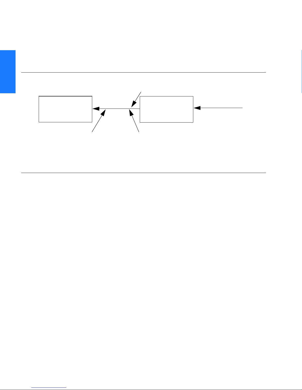
Figure 8 shows a TimeSource 3500 Passthrough setup.
1
Figure 8. TimeSource 3500 Passthrough Function
Straight cable
DCD-5X
COM 1, 2, COM 1 or 2 (COM 1 is
or 3
Alarm Programmability
Releases of TimeSource (1.05.03 and above) allow the user to
provision the alarm escalation parameters that were hardcoded in
the previous releases of TS3000.hex. The defaults for this release
remain the same as were previously hardcoded. This feature can
be used to set the programmability for such alarms as GPS,
HOLDOVER, SPAN-X, and RO-X.
DCDPASSTHRU
User port (any port)
TS-3500
DCDUSERPORT
COM 1, 2, 3
IP: 5001 - 5004
DB-25 and COM 2 is
RJ-45)
The TS3500 alarms can be programmed for GPS and HOLDOVER
types of events. The SPAN-X alarms can be programmed for AIS,
ERROR, and LOS types of events. The RO-X alarms can be
programmed for ERROR and LOS types of events.
The user can set the parameters for SEVERITY1 and SERAFF1
which initially come into effect when the condition is detected. The
user can also set the parameters for SEVERITY2 and SERAFF2
which come into effect after TIME (another user programmable
parameter).
38 TimeSource 3500
Description
097-72050-01 Issue 7: August 2003
Page 39

SSSSSSSSSSSS SSSSSSSSSS SSSSSSS
Startup
When the TimeSource starts up, the CRIT lamp lights. The CRIT
lamp remains on for approximately 50 seconds to 60 seconds and
then shuts off.
During startup, the TimeSource performs several self-tests to
verify the integrity of the hardware and software. Neither
communication nor outputs are possible at this time, and the
CRIT lamp is switched on. Once the self-tests are done, a
connection to the system can be made and the events viewed.
Two events are initially provided. These events are:
• "Power Up Restart"
• "Settling Period"
In the "Power Up Restart" event, which lasts for approximately 2
minutes, the system does additional checks and starts all the
various tasks within the system.
The "Settling Period" event is an informational message that lasts
until the TimeSource’s BesTime engine reaches the highest
possible stable point. The time taken to reach this point depends
on satellite availability, type of oscillator, ambient temperature,
etc. and may take up to 20 hours to clear. Since "Settling Period"
is independent of the quality of the output and is the normal
behavior of the system, it is generated as an event rather than an
alarm. If "Settling Period" is not cleared after 24 hours, another
"Settling Period" event is generated as a marker. This is still NonService-Affecting.
1
2
3
4
As soon as the "Power Up Restart" message is cleared, the "BT3
Warmup" event is generated. This is also an informational
message that lasts till the time it takes the system to acquire the
satellites, warm up the oscillator, and start giving out valid
outputs. It may take up to 2 hours for the message to clear, but
typically takes approximately 40 minutes. During the "BT3
Warmup" time, the outputs will generally be squelched. If the
TimeSource 3500 39
Description
097-72050-01 Issue 7: August 2003
5
Page 40

1
SSSSSSSSSSSS SSSSSSSSSS SSSSSSS
outputs are enabled using the TL1 command
(ED-EQPT::TS3500:ctag:::ALMCOND=ALW;) they may not be within the
PRS mask. In case the system is not able to acquire sufficient
number of satellites and/or discipline the oscillator within 2
hours, the event escalates into a Non Service Affecting Minor
alarm.
Once the warm up is complete, the system generates valid outputs
and the event is cleared.
Bridging/Holdover Behavior
In the TimeSource 3500, alarms are designed with a built-in
hysteresis. This means that an alarm is not announced as soon as
some error condition is detected. There is a pre-integration time
during which the error must persist in order for the alarm to be
announced. On the flip side, the error must be clear for a certain
time for an alarm condition to be cleared. This ensures that
intermittent conditions are not flagged unnecessarily.
During the normal working of the TimeSource 3500, it is a very
common occurrence that the GPS satellites may not be visible
during certain parts of the day, depending on the installation of
the antenna. This is particularly true with wall and, especially,
window antenna installations. The TimeSource 3500 has been
designed to work around this situation.
The TimeSource 3500 enters "Bridging" mode when all satellite
locks are lost. There is no TL1 annunciation that the system has
entered "Bridging" mode. This is "Non Service Affecting" and the
outputs are not affected. The system runs off its internal oscillator
and the outputs are kept within the GR-2830 PRC mask by the
BesTime engine.
When "Bridging" mode persists for more than 30 minutes, the
system enters "Holdover" mode and a "Holdover" event is
generated. This may or may not affect the outputs depending on
the alarm integration parameters that can be set by the user.
40 TimeSource 3500
Description
097-72050-01 Issue 7: August 2003
Page 41

SSSSSSSSSSSS SSSSSSSSSS SSSSSSS
The system allows the user to set various parameters for GPS
error, Holdover error, and SPAN error conditions. These
parameters are:
• Initial Severity
• Initial Service Affecting state
• Integration Time
•Final Severity
• Final Service Affecting state
The system also allows the user to set a parameter to define how
outputs should behave in an alarm condition. Outputs can be set
to AIS, Squelch, or SSM on an alarm. Outputs can also be set to
ignore alarm conditions.
1
2
When the "Holdover" event is announced, it is announced with the
Initial Severity and Initial Service Affecting state. If the "Holdover"
event persists for the length of the Integration Time, the alarm is
escalated to the Final Severity and Final Service Affecting state.
The "Holdover" event/alarm is cleared when the satellites are
visible again.
3
4
5
TimeSource 3500 41
Description
097-72050-01 Issue 7: August 2003
Page 42

SSSSSSSSSSSS SSSSSSSSSS SSSSSSS
Time Figure of Merit
1
Time Figure of Merit (TFOM) is a moving 24 hour measurement
reported in nanosecond (ns) against an ideal model. TFOM has a
frequency component used to measure GPS wander caused by
multipath and a time loop component used to measure long term
oscillator wander.
The TFOM alarm threshold is set to 500 ns and is not user
configurable. A TFOM below 500 ns indicates a stable clock well
within PRS output performance specifications. A TFOM between
500 ns and 800 ns is an early warning of a clock becoming
unstable and in danger of going out of PRS specification. When the
TFOM exceeds 800 ns, the clock is no longer meeting the stratum
1 MTIE mask.
TFOM is most useful for installations where the antenna has a
limited view to the sky. This is defined as any installation where
fewer than 4 satellites are in view for greater than 1 hour per day
on average. This is typical for installations where the antenna is
mounted in a window or on an outside wall of a building, but can
also include rooftop installations with partial sky view blockage.
TFOM’s primary use is to help troubleshoot multipath issues
associated with antenna placement and incorrect latitude,
longitude, and/or altitude (location) data entry.
Installations with full view to the sky see 4 satellites 23+ hours a
day, seven days a week. It is relatively easy to filter out multipath
signals using multiple satellites and simple voting schemes. In
addition, rooftop antennas are mounted vertically and all signals
below the horizon are obvious multipath interference and can be
masked out of the system. With 4 satellites in view, the GPS
timing receiver will provide an error-free lock on its location
through an automatic survey function.
With wall/window installations, voting schemes become less
effective as the number of satellites in view drop. Also, wall/
window antennas are mounted horizontally and are prone to
seeing multipath signals reflected off nearby structures and the
42 TimeSource 3500
Description
097-72050-01 Issue 7: August 2003
Page 43

SSSSSSSSSSSS SSSSSSSSSS SSSSSSS
ground. Wall/window installations also require the manual input
of location data, creating the potential for errors and the need to
detect these errors.
The TimeSource has unique algorithms to account for, and defeat,
the added multipath complications and location data entry error
possibilities of wall/window antenna installations. Large amounts
of multipath or major errors in location data entry are easier to
identify and are detected over a relatively short period of time.
These short-term errors are normally reported via the TimeSource
tracking success rate parameter.
Small amounts of multipath or minor errors in location data entry
are difficult to identify because they mimic a true signal or an
expected satellite behavior pattern. Single satellite reception over
limited periods of time complicates the ability for the internal
TimeSource algorithms to filter out these ghost signals and longer
periods of time are needed to sort them out. TFOM tracks and
reports these long-term errors.
1
2
At time of installation, marginal or unacceptable TFOM readings
can indicate the need to adjust the antenna placement, the mask
angle, and/or the location data. Relatively small changes in the
antenna placement can improve the ability of the system to see
satellites and therefore improve performance. The mask angle can
be adjusted to block out lower elevation portions of the sky if there
is good visibility at higher elevations, thereby reducing multipath.
Correct location data is very helpful in identifying and tracking
satellites.
In addition, a clock may be stable for many weeks, months, or
years but could degrade because of changes in its environment.
TFOM is useful in detecting these infrequent subtle changes
including:
• Maturing foliage or seasonal foliage changes
• Installation of new transmitters nearby (i.e. wireless base station)
3
4
5
TimeSource 3500 43
Description
097-72050-01 Issue 7: August 2003
Page 44

1
SSSSSSSSSSSS SSSSSSSSSS SSSSSSS
• New building construction
• Variations in the day-to-day temperature of the CO
44 TimeSource 3500
Description
097-72050-01 Issue 7: August 2003
Page 45

Engineering
& Ordering
This chapter provides information to
assist in planning the installation and
ordering a system appropriate for a
specific site.
Chapter
2
Page 46

2
SSSSSSSSSSSS SSSSSSSSSS SSSSSSS
Antenna Guidelines
Perform a site survey as described in Procedure A before ordering
the system. Use the guidelines and considerations in the Roof/
Window/Wall Antenna Location and Cabling Guidelines section
and the Shelf Considerations section.
46 TimeSource 3500
Engineering & Ordering
097-72050-01 Issue 7: August 2003
Page 47

SSSSSSSSSSSS SSSSSSSSSS SSSSSSS
Procedure A. Site Survey
Step Action
1
2 Determine the best location for mounting the antenna (less than 1,000 ft of cable
3 If a roof-mounted antenna is installed, determine the location of the grounding
4 If a roof-mounted antenna is installed, two lengths of cable are required. Plan the
Determine the shelf location.
from the shelf). Use the guidelines and considerations in the Roof Antenna
Location and Cabling Guidelines section.
point for the lightning suppressor, then determine the location of the lightning
suppressor. The cable length between the lightning suppressor and the grounding
point must be less than 15 ft. If the grounding point is inside the building, the
cable length between the grounding point and the cable entry must be less than
50 ft. Valid lightning suppressor grounding points are:
• Valid ring ground system (usually for roof-mounted lightning suppressors)
• Structural steel of building (for interior-mounted or exterior-mounted lightning
suppressors, attach with a cad weld)
• Central Office ground plate (usually for interior-mounted lightning suppressors)
cable route and measure the length of cable required between the antenna and
the lightning suppressor, and between the lightning suppressor and the shelf.
2
3
5 If a window or wall-mounted antenna is installed, plan the cable route and
measure the length of cable required between the antenna and the shelf.
6 Determine the two separate –48 V power sources for the shelf. If only one –48 V
power source is available, it must be cabled to both TimeSource 3500 power
inputs.
End of Procedure
TimeSource 3500 47
Engineering & Ordering
097-72050-01 Issue 7: August 2003
4
5
Page 48

SSSSSSSSSSSS SSSSSSSSSS SSSSSSS
Roof Antenna Location and Cabling Guidelines
DANGER: Do not select an antenna location that could be
an electrical or physical hazard to work persons or
equipment. Avoid proximity to all high-voltage sources.
Mount in an easily maintainable location.
The ideal roof antenna location provides a clear, unobstructed
view of the sky from the zenith to the horizon line, and 360
degrees around the horizon.
2
A compromise often must be made between location and satellite field
of view. With a smaller field of view, the TimeSource 3500 can use
fewer satellites in the solution for GPS derived time. The TimeSource
3500 will operate with an average of one satellite in view for 40 percent
of the time in a day.
Signals closer to the horizon are often subject to multipath effects,
which degrade the timing solution. The TimeSource 3500 can be
set to ignore, or mask, all signals from the horizon up to a chosen
angle of elevation (mask angle). (See Figure 9.)
48 TimeSource 3500
Engineering & Ordering
097-72050-01 Issue 7: August 2003
Page 49

SSSSSSSSSSSS SSSSSSSSSS SSSSSSS
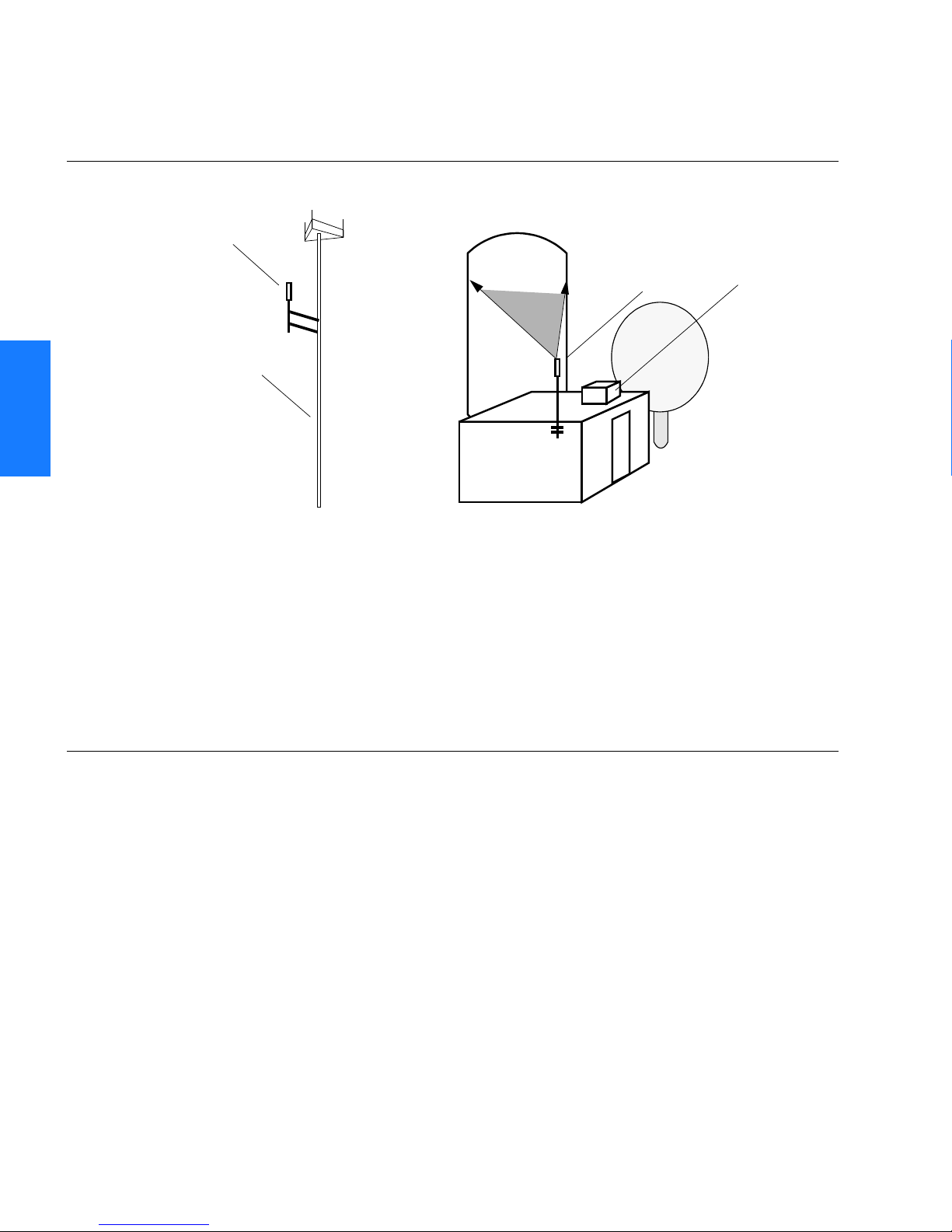
Figure 9. Antenna Field of View
Antenna position
Antenna
field of view
Obstructions
toward the pole
if possible
Mask angle*
10°
Horizon
Equator
* An angle of 10° masks objects up to about 3.5 ft above the
horizon at 20 ft from the antenna (illustration at right.)
Due to the geometry of the GPS satellite orbits, more satellites are
visible in the direction of the equator than the poles. If possible, place
the antenna so that the antenna has a clear view toward the equator
(toward the south in the northern hemisphere, or toward the north in
the southern hemisphere). Up to 60 degrees of arc, centered at the
pole, may be blocked with little effect in the temperate latitudes. This
note is less applicable in latitudes nearer the equator.
The total of obstructions above the mask angle should not obscure
more than 25 percent of the total field of view (90 degrees of
azimuth) (Figure 10).
10°
10°
Mask angle*
Pole
20 ft
2
3.5 ft
3
4
TimeSource 3500 49
Engineering & Ordering
097-72050-01 Issue 7: August 2003
5
Page 50
SSSSSSSSSSSS SSSSSSSSSS SSSSSSS
Figure 10. Antenna Location Examples
2
Antenna tower
antenna
location
(Note 1)
Antenna
tower
Location A Location B
Notes:
1. Place the antenna high enough on the tower that obstructions are below the mask angle;
mount the antenna more than 3 feet away from the tower, and far below the interference
of the antennas at the top of the tower. Tower mounting is the least desirable location because of the potential for severe multipath, and difficulty in troubleshooting and maintenance.
2. Place the antenna high enough that the roof structure and tree are below the mask angle,
and the water tower does not block more than 12.5 percent of the sky.
Water
tower
Building
antenna
location
(Note 2)
Tree
Roof
structure
No single obstruction should block a large portion (45 degrees of
azimuth) of the view.
The most important obstructions are within 1/4 mile (400 yards)
of the antenna. Obstructions may include, but are not limited to,
towers, buildings, other construction, trees, and high-voltage
power lines.
Attempt to avoid locating the antenna within 30 degrees azimuth
of the transmission direction of any transmitting antenna in the
area, even if the transmitting antenna operates at a different
50 TimeSource 3500
Engineering & Ordering
097-72050-01 Issue 7: August 2003
Page 51

SSSSSSSSSSSS SSSSSSSSSS SSSSSSS
frequency. A transmitting antenna may cause the GPS antenna to
become overloaded and reduce its reception capabilities.
The minimum horizontal distance from other receiving antennas is
3 feet.
To reduce multipath signal distortions, the minimum horizontal
distance from vertical reflective structures (e.g., heating ducts,
equipment housings, etc.) is twice the height of the structure, and
no less than 10 feet (Figure 11).
Do not locate the antenna underneath high power lines. If this
cannot be avoided, ensure the antenna is placed at least twice as
far from the power line as the power line is high (to avoid danger
to personnel and multipath effects).
Cables must be run as straight as possible. All cables should be
routed in accordance with local company practices.
Note: Keep all impedances as low as possible, otherwise the
grounding scheme may be defeated.
Observe the following guidelines during the placement and
installation of the cables:
• Route cables as straight as possible (bends in the cable
increase impedance at lightning frequencies), in accordance
with local company practices.
• Any opening where conduit enters the building must be
waterproofed per local company practices.
2
3
4
• Treat all exposed connections with an electrically conductive
anti-corrosion compound (Kopr-Shield or equivalent).
Warning: Avoid small-radius turns and unnecessary turns.
TimeSource 3500 51
Engineering & Ordering
097-72050-01 Issue 7: August 2003
5
Page 52
2
SSSSSSSSSSSS SSSSSSSSSS SSSSSSS
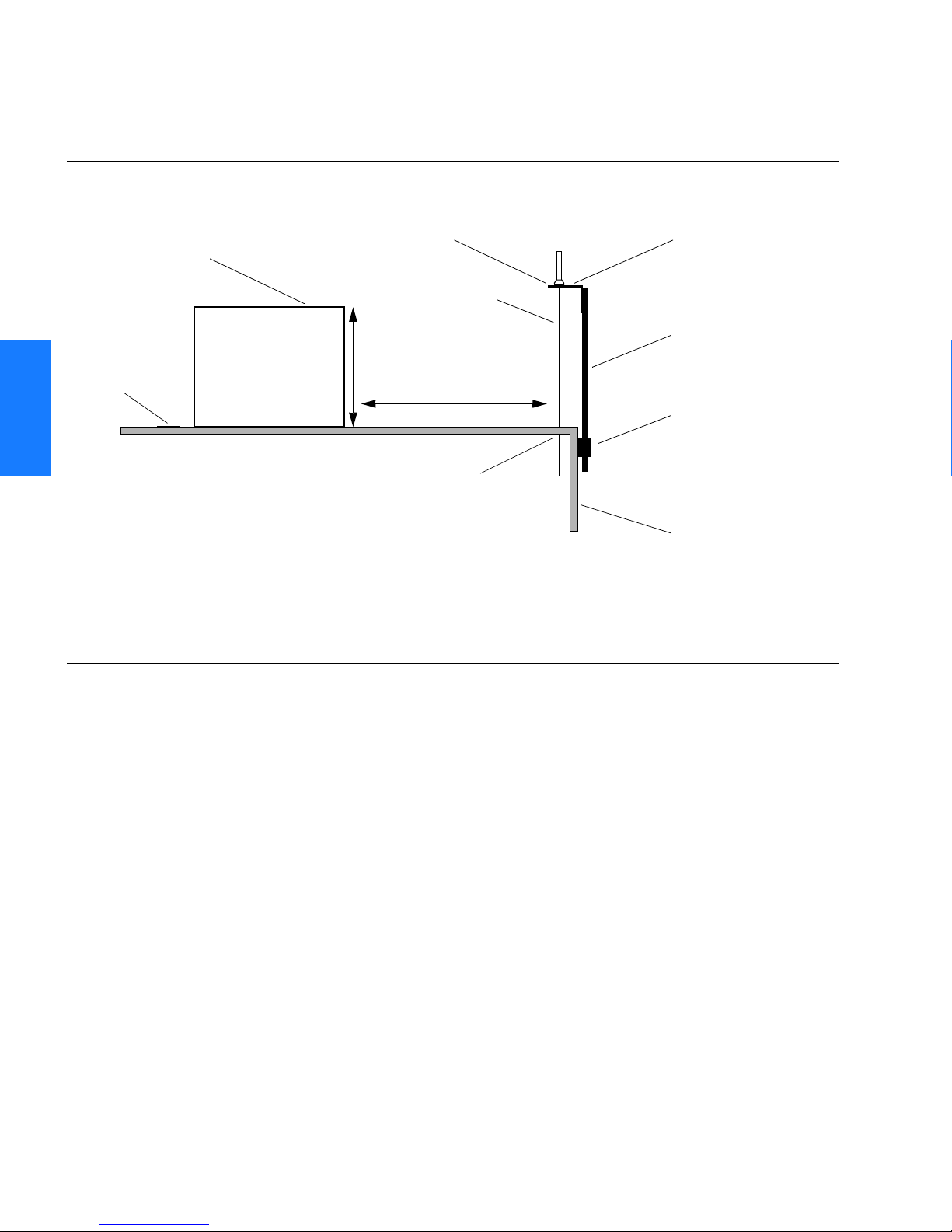
Figure 11. Sample Rooftop Antenna Mount
At or above the
level of the
Reflective
surface
reflective surface
Cable
conduit
8 ft
Rooftop
Heating
Ducts
(twice the 8 ft height)
16 ft
(10 ft minimum)
Cable entry
into building
Antenna
Mounting
Bracket
Mounting Pipe
Pipe clamped
to wall
Building Wall
Note: This is an example only. Not all parts are available from Symmetricom.
52 TimeSource 3500
Engineering & Ordering
097-72050-01 Issue 7: August 2003
Page 53

SSSSSSSSSSSS SSSSSSSSSS SSSSSSS
Roof Antenna Earth Ground Location Guidelines
The roof ring ground system, a Central Office grounding plate, and
building structural steel are examples of valid earth ground
points. If the mounting plate cannot be bolted to a valid earth
ground, or if the mounting plate is to be installed in a nonmetallic
junction box, bolt the mounting plate to a point within 15 feet of
the valid earth ground.
2
3
4
5
TimeSource 3500 53
Engineering & Ordering
097-72050-01 Issue 7: August 2003
Page 54

2
SSSSSSSSSSSS SSSSSSSSSS SSSSSSS
Roof Antenna Cable Choices
The antenna assembly uses the same coaxial cable for power and
antenna signals. The length of cable is determined by
circumstances of the installation and site.
Symmetricom offers RG-59/U plenum-rated coaxial cable (20 AWG
[0.812 mm], 75 ohm coaxial) with male TNC connectors attached,
in the following lengths:
• 10 feet (060-72010-01)
• 20 feet (060-72010-02)
• 50 feet (060-72010-05)
• 100 feet (060-72010-10)
• 200 feet (060-72010-20)
• 300 feet (060-72010-30)
• 500 feet (060-72010-50)
• 600 feet (060-72010-60)
• 800 feet (060-72010-80)
• 1000 feet (060-72010-99)
Two cables are required: one to connect the antenna to the
lightning suppressor, and another to connect the lightning
suppressor to the TimeSource 3500 Shelf.
Optionally, one length of coaxial cable may be ordered, which
must be cut and prepared with end-connectors at the point where
the suppressor is located.
54 TimeSource 3500
Engineering & Ordering
097-72050-01 Issue 7: August 2003
Page 55

SSSSSSSSSSSS SSSSSSSSSS SSSSSSS
The following items, which must be ordered separately, are
available for this type of installation:
• TNC connector kit (093-72010-98) includes:
- TNC connectors for RG-59/U cables (8)
-Rubber boots (8)
- TNC adapter connectors (2)
• TNC crimp tool (154-00023-01)
2
3
4
5
TimeSource 3500 55
Engineering & Ordering
097-72050-01 Issue 7: August 2003
Page 56

SSSSSSSSSSSS SSSSSSSSSS SSSSSSS
Window and Wall Antenna Location Guidelines
When selecting a window or wall in which to install the antenna,
select the window or wall which has the maximum unobstructed
view of the sky. Do not select a window or wall which has the view
of the sky obstructed by trees, buildings, or towers. The smaller
the field of view, the fewer the number of satellites that can be
used in the timing solution for GPS derived time. The consequence
of this is that the timing generator may experience holdover more
often and may eventually go into alarm.
2
Due to the geometry of the GPS satellite orbits, more satellites are
visible in the direction of the equator than the poles. If possible,
select a window or wall which has a clear view toward the equator
(toward the south in the northern hemisphere, or toward the north
in the southern hemisphere). This guideline is less applicable in
latitudes nearer the equator and more important nearer the poles.
Certain parts of the sky are blocked from view. These obstructions
usually exist from the horizon line and up, for example, a building
or mountain. The processor inside the GPS receiver possesses
every piece of the sky, whether it is blocked or not. If unproductive
parts of the sky are masked from the processor’s view, the
processing time is reduced, and the timing solution can be
achieved more quickly.
Note: A band of the sky from the horizon up to a point where a
view of the sky begins is called a mask angle. The mask angle typically should not exceed 10 degrees (if the mask angle is set too
high, too little of the sky is available to the receiver). Determine the
mask angle for the selected antenna location (Figure 12) and make
a note of it. The mask angle, in degrees, will be entered during the
initial setup.
56 TimeSource 3500
Engineering & Ordering
097-72050-01 Issue 7: August 2003
Page 57

SSSSSSSSSSSS SSSSSSSSSS SSSSSSS
Figure 12. Antenna Mask Angle
10° mask angle*
TimeSource 3500
Antenna
20 ft
*An angle of 10° masks objects up to about 3.5 ft above the horizon at
20 ft from the antenna.
3.5 ft
Note: TimeSource 3500 does
not detect satellites in the
masked area.
2
3
4
5
TimeSource 3500 57
Engineering & Ordering
097-72050-01 Issue 7: August 2003
Page 58

2
SSSSSSSSSSSS SSSSSSSSSS SSSSSSS
Window and Wall Antenna Cable Choices
A window or wall antenna includes an attached coaxial cable
terminating in a male SMA connector.
A separate cable is required to connect the IF converter to the
TimeSource 3500 shelf. Two types of plenum-rated cable are available.
The cables with longer length capabilities (060-72010-xx) are
RG-59/U (20 AWG [0.812 mm], 75 ohm coaxial) with male TNC
connectors attached to each end. Assembled cables are available
in the following lengths:
• 10 feet (060-72010-01)
• 20 feet (060-72010-02)
• 50 feet (060-72010-05)
• 100 feet (060-72010-10)
• 200 feet (060-72010-20)
• 300 feet (060-72010-30)
• 500 feet (060-72010-50)
• 600 feet (060-72010-60)
• 800 feet (060-72010-80)
• 1000 feet (060-72010-99)
58 TimeSource 3500
Engineering & Ordering
097-72050-01 Issue 7: August 2003
Page 59

SSSSSSSSSSSS SSSSSSSSSS SSSSSSS
The more flexible cables (060-72050-xx) are Mini RG-59/U
(20 AWG [0.812 mm], 75 ohm coaxial) with male TNC connectors
attached to each end. Assembled cables are available in the
following lengths:
• 50 feet (060-72050-05)
• 100 feet (060-72050-10)
• 200 feet (060-72050-20)
• 500 ft (060-72050-50)
2
3
4
5
TimeSource 3500 59
Engineering & Ordering
097-72050-01 Issue 7: August 2003
Page 60

2
SSSSSSSSSSSS SSSSSSSSSS SSSSSSS
IRIG-B TOD (990-72050-05 System Only)
If using the IRIG-B TOD outputs (990-72050-05 TimeSource 3500
System), right-angle BNC connectors are provided to prevent small
radius turns in the IRIG-B TOD cables. The right-angle BNC
connectors may be attached to the IRIG-B BNC adapter (also
provided) BNC connectors, to direct the cables from the shelf as
desired.
For each IRIG-B TOD output, a user-supplied cable with BNC
connectors on each end is installed between the adapter and the
network elements requiring IRIG-B TOD timing.
60 TimeSource 3500
Engineering & Ordering
097-72050-01 Issue 7: August 2003
Page 61

SSSSSSSSSSSS SSSSSSSSSS SSSSSSS
RJ-422–to–RS-232 TOD Converter
If using time-of-day (TOD), and the device receiving the time code
accepts an RS-232 signal instead of an RS-422 signal (for
example, a Cisco router), an RJ-422–to–RJ-232 TOD Converter Kit
is required (ordered separately, part number 093-72000-98).
The RJ-422–to–RJ-232 TOD Converter Kit consists of a mounting
plate with a female RJ-45 connector, a female DB-25 connector, a
TOD converter, and two screws.
Install the converter anywhere (for example, on unused space on a
rack) within 1,000 cable feet of the TimeSource 3500 shelf, and
within 50 cable feet of the device receiving the time code.
The user must supply two cables. One cable is a Category 5 fourpair RS-422 cable, 1,000 feet maximum, with RJ-45 connectors on
each end. Route this cable between the TimeSource 3500 Shelf
and the converter.
The other cable is an RS-232 data communications cable, 50 feet
maximum, with a 25-pin male D-type connector and another
connector determined by the device receiving the time code. Route
this cable between the converter and the device receiving the time
code.
2
3
4
TimeSource 3500 61
Engineering & Ordering
097-72050-01 Issue 7: August 2003
5
Page 62

2
SSSSSSSSSSSS SSSSSSSSSS SSSSSSS
Shelf Considerations
The TimeSource 3500 Shelf can be mounted in a 19 inch rack or a
23 inch rack. The shelf is shipped with supplied mounting ears
positioned for flush mounting on a 23 inch rack. Attach the
mounting ears, as shown in Figure 13, for flush mounting or 5
inch offset mounting. Attach the long side of the mounting ear to
the shelf for a 23 inch rack, and attach the short side of the
mounting ears to the shelf for a 19 inch rack. Mount the shelf in
the rack according to standard company practices. Leave one RU
(1.75 inches) of air space above the TimeSource 3500 Shelf for
proper ventilation. Mount the shelf in the rack according to
standard company practices.
Note: Two screws can be used in each mounting ear if the holes
in the rack are spaced 1.75 inches apart.
Figure 13. Rack Mounting Options
Rear of rack
Top of shelf
A. Flush mounting – 19 in. rack
Rear of rack
Top of shelf
C. 5 in. offset – 19 in. rack
Rear of rack
Top of shelf
B. Flush mounting – 23 in. rack
Rear of rack
Top of shelf
D. 5 in. offset – 23 in. rack
62 TimeSource 3500
Engineering & Ordering
097-72050-01 Issue 7: August 2003
Page 63

SSSSSSSSSSSS SSSSSSSSSS SSSSSSS
Systems
The TimeSource 3500 Systems available are listed below. The
antenna must be ordered separately.
2
3
4
5
TimeSource 3500 63
Engineering & Ordering
097-72050-01 Issue 7: August 2003
Page 64

SSSSSSSSSSSS SSSSSSSSSS SSSSSSS
Standard System (Two T1 Outputs)
This system (990-72050-01) includes:
• TimeSource 3000 Shelf (090-72000-01)
• TimeSource 3500 card (090-72050-01)
• Hardware kit (093-72050-87)
• System software compact disc (CD) (992-72050-xx) Version
1.05.04 or higher
2
• TimeScan Craft (keyless version) software CD (992-46750-xx)
Version 7.2.0 or higher
64 TimeSource 3500
Engineering & Ordering
097-72050-01 Issue 7: August 2003
Page 65

SSSSSSSSSSSS SSSSSSSSSS SSSSSSS
With Eight Additional T1 Outputs
This system (990-72050-02) includes:
• TimeSource 3000 Shelf (090-72000-01)
• TimeSource 3500 card with additional T1 outputs
(090-72050-02)
• Hardware kit (093-72050-87)
• System software CD (992-72050-xx)
Version 1.05.04 or higher
• TimeScan Craft (keyless version) software CD (992-46750-xx)
Version 7.2.0 or higher
2
3
4
5
TimeSource 3500 65
Engineering & Ordering
097-72050-01 Issue 7: August 2003
Page 66

SSSSSSSSSSSS SSSSSSSSSS SSSSSSS
With Eight Additional Mixed E1/T1 Outputs
This system (990-72050-06) includes:
• TimeSource 3000 Shelf (090-72000-01)
• TimeSource 3500 card with mixed E1/T1 outputs
(090-72050-06)
• Hardware kit (093-72050-87)
2
• System software CD (992-72050-xx)
Version 1.05.04 or higher
• TimeScan Craft (keyless version) software CD (992-46750-xx)
Version 7.2.0 or higher
66 TimeSource 3500
Engineering & Ordering
097-72050-01 Issue 7: August 2003
Page 67

SSSSSSSSSSSS SSSSSSSSSS SSSSSSS
With Eight Additional Mixed T1/CCK Outputs
This system (990-72050-07) includes:
• TimeSource 3000 Shelf (090-72000-01)
• TimeSource 3500 card with mixed T1/CCK outputs
(090-72050-07)
• Hardware kit (093-72050-87)
• System software CD (992-72050-xx)
Version 1.06.02 or higher
• TimeScan Craft (keyless version) software CD (992-46750-xx)
Version 7.2.0 or higher
2
3
4
TimeSource 3500 67
Engineering & Ordering
097-72050-01 Issue 7: August 2003
5
Page 68

2
SSSSSSSSSSSS SSSSSSSSSS SSSSSSS
With Eight Composite Clock Outputs
This system (990-72050-03) includes:
• TimeSource 3000 Shelf (090-72000-01)
• TimeSource 3500 card with composite clock outputs
(090-72050-03)
• Hardware kit (093-72050-87)
• System software CD (992-72050-xx)
Version 1.05.04 or higher
• TimeScan Craft (keyless version) software CD (992-46750-xx)
Version 7.2.0 or higher
68 TimeSource 3500
Engineering & Ordering
097-72050-01 Issue 7: August 2003
Page 69

SSSSSSSSSSSS SSSSSSSSSS SSSSSSS
With Two IRIG-B TOD Outputs
This system (990-72050-05) includes:
• TimeSource 3000 Shelf (090-72000-01)
• TimeSource 3500 card with IRIG-B TOD outputs
(090-72050-05)
• IRIG-B BNC adapter board (090-72100-06)
• Two right-angle BNC connectors (121-00530-01)
• Hardware kit (093-72050-87)
• System software CD (992-72050-xx)
Version 1.05.04 or higher
• TimeScan Craft (keyless version) software CD (992-46750-xx)
Version 7.2.0 or higher
2
3
4
5
TimeSource 3500 69
Engineering & Ordering
097-72050-01 Issue 7: August 2003
Page 70

2
SSSSSSSSSSSS SSSSSSSSSS SSSSSSS
Antennas
The antennas available are listed below. A TimeSource 3500
System must be ordered separately.
70 TimeSource 3500
Engineering & Ordering
097-72050-01 Issue 7: August 2003
Page 71

SSSSSSSSSSSS SSSSSSSSSS SSSSSSS
Roof Antenna
This antenna kit (990-72050-96) includes:
• IF antenna assembly (090-72010-97)
• Rooftop antenna installation kit (093-72050-96) includes:
- Antenna cable bracket kit (070-00377-01)
- Mounting bracket for surge suppressor (070-00300-02)
- Surge suppressor (143-00018-01)
- Miscellaneous installation parts
2
3
4
TimeSource 3500 71
Engineering & Ordering
097-72050-01 Issue 7: August 2003
5
Page 72

2
SSSSSSSSSSSS SSSSSSSSSS SSSSSSS
Mechanical Window Antenna
This antenna kit (990-72050-97) comes as a fully assembled
antenna with the following major components:
• Antenna, with cable and SMA connector attached
(090-72050-90)
• IF converter (090-72050-97)
• Mechanical chassis (074-72050-97)
72 TimeSource 3500
Engineering & Ordering
097-72050-01 Issue 7: August 2003
Page 73

SSSSSSSSSSSS SSSSSSSSSS SSSSSSS
Self-Adhesive Window Antenna
This antenna kit (990-72050-98) includes:
• Antenna (090-71010-87)
• IF converter (090-72050-97)
• Self-adhesive window antenna installation kit (093-72050-98)
includes:
- RG316 cable, 10 feet (060-00062-01)
- Cable tie mounts (128-00302-02) and
cable ties (128-00500-05)
2
3
4
5
TimeSource 3500 73
Engineering & Ordering
097-72050-01 Issue 7: August 2003
Page 74

2
SSSSSSSSSSSS SSSSSSSSSS SSSSSSS
Wall Antenna
Order one of these two available wall antenna kits based on the
users antenna cable length installation requirements:
This antenna kit (990-72050-99) includes:
• IF converter (090-72050-97)
• Wall antenna kit (093-72050-99) includes:
- Antenna, with 19 feet of cable and SMA connector
attached (112-00013-01)
- Antenna mounting bracket (070-00383-02)
- Clamp tie mounts (128-00302-02) and
cable ties (128-00500-05)
OR
This antenna kit (990-72050-95) includes:
• IF converter (090-72050-97)
• Wall antenna kit (093-72050-95) includes:
- Antenna, with 6 feet of cable and SMA connector attached
(112-00013-03)
- Antenna mounting bracket (070-00383-02)
- Clamp tie mounts (128-00302-02) and
cable ties (128-00500-05)
74 TimeSource 3500
Engineering & Ordering
097-72050-01 Issue 7: August 2003
Page 75

SSSSSSSSSSSS SSSSSSSSSS SSSSSSS
Wall Antenna (cont’d)
• Wall antenna indoor lightning suppressor kit (093-72050-94)
(optional) includes:
- Mounting bracket (070-00300-02)
- Surge protector (143-00018-01)
- RG59 cable, 2 feet (060-72010-92)
• Wall antenna L1 outdoor lightning suppressor kit (09372050-93) (optional) includes:
- Mounting bracket (070-00300-03)
- Surge protector (143-00018-02)
- RG316 cable, 10 feet, SMA(m)-SMA(m) (060-00062-01)
2
3
4
TimeSource 3500 75
Engineering & Ordering
097-72050-01 Issue 7: August 2003
5
Page 76

2
SSSSSSSSSSSS SSSSSSSSSS SSSSSSS
User-Supplied Tools and Materials
Ensure that the user-supplied tools and materials listed below are
on hand for installation, as applicable.
76 TimeSource 3500
Engineering & Ordering
097-72050-01 Issue 7: August 2003
Page 77

SSSSSSSSSSSS SSSSSSSSSS SSSSSSS
For Roof Antenna Installation
• 1 inch diameter galvanized metal pipe, used as a mast to
mount the antenna. Mast should be long enough to position
the antenna above any metal object on the roof.
• Screws to attach the lightning suppressor mounting plate.
• Plumb line or bubble level.
• Nonmetallic junction box for lightning suppressor (optional if
lightning suppressor mounted indoors).
• 1 inch diameter PVC pipe as conduit for outdoor cables.
• PVC fittings appropriate to the installation and cable route.
• Appropriate tools and materials for cutting, shaping, and
connecting PVC pipe.
2
•6 AWG ground wire.
• Spade lugs for 6 AWG ground wire.
• Crimp tool for 6 AWG spade lugs.
• Hardware to attach the ground wire to a valid earth ground.
• Fire-stopping material to seal conduit hole in roof or wall.
• Electrically conductive antioxidant compound (Kopr-Shield or
equivalent) to coat exposed connections to prevent oxidation.
• Tool to cut cable, if installation requires custom lengths of
cable.
3
4
5
TimeSource 3500 77
Engineering & Ordering
097-72050-01 Issue 7: August 2003
Page 78

SSSSSSSSSSSS SSSSSSSSSS SSSSSSS
For Mechanical Window Antenna Installation
• Drill with bit of appropriate size and type to make pilot holes
for the mounting screws
• 2 screws of appropriate size and type to attach the foot of the
mechanical chassis to a window sill or wall near a window.
• Screwdriver
• Cable ties or other method of securing cable
2
• GPS handheld receiver, personal computer with GPS location
software, or other method of determining latitude, longitude,
and altitude
78 TimeSource 3500
Engineering & Ordering
097-72050-01 Issue 7: August 2003
Page 79

SSSSSSSSSSSS SSSSSSSSSS SSSSSSS
For Self-Adhesive Window Antenna Installation
• Drill with bit of appropriate size and type to make pilot holes
for the mounting screws
• 4 screws of appropriate size and type to attach the IF
converter to a wall or other mounting surface.
• Screwdriver
• GPS handheld receiver, personal computer with GPS location
software, or other method of determining latitude, longitude,
and altitude
2
3
4
5
TimeSource 3500 79
Engineering & Ordering
097-72050-01 Issue 7: August 2003
Page 80

2
SSSSSSSSSSSS SSSSSSSSSS SSSSSSS
For Wall Antenna Installation
• Ladder, or safe method of reaching the antenna location on
the exterior wall
• Drill with bits of appropriate size and type to make pilot holes
for the antenna mounting bracket screws, and to make a
hole through the wall for the antenna cable
• 2 screws of appropriate size and type to attach the antenna
mounting bracket to an exterior wall.
• Screwdriver
• Electrically conductive antioxidant compound (Kopr-Shield
or equivalent) to coat exposed connections to prevent
oxidation
• Fire stopping material to seal the hole in the wall
• GPS handheld receiver, personal computer with GPS location
software, or other method of determining latitude, longitude,
and altitude
80 TimeSource 3500
Engineering & Ordering
097-72050-01 Issue 7: August 2003
Page 81

SSSSSSSSSSSS SSSSSSSSSS SSSSSSS
For Shelf Installation
• A Phillips-head screwdriver for installing the TimeSource
3500 Shelf in a rack
• Four screws to mount the shelf in a rack
2
3
4
5
TimeSource 3500 81
Engineering & Ordering
097-72050-01 Issue 7: August 2003
Page 82

SSSSSSSSSSSS SSSSSSSSSS SSSSSSS
Outputs, Power, and Miscellaneous
• RG-58 coaxial cable for 1 PPS, 10 MHZ outputs
• Ethernet 10BaseT cable for Ethernet port
• Category 5 four-pair RS-422 cable, with RJ-45 connector for
the TOD output, RS-422–to–RS-232 TOD converter
• RS-232 cable with DB-25 connector for the RS-422–to–
RS-232 TOD converter
2
• RS-232 cable with DB-9 connector for COM2 port
•6AWG ground wire
• 16 AWG green insulated ground wire
• 16 AWG red insulated wire
• 16 AWG black insulated wire
• T1 cables
82 TimeSource 3500
Engineering & Ordering
097-72050-01 Issue 7: August 2003
Page 83

SSSSSSSSSSSS SSSSSSSSSS SSSSSSS
This page intentionally left blank.
2
3
4
5
TimeSource 3500 83
Engineering & Ordering
097-72050-01 Issue 7: August 2003
Page 84

2
SSSSSSSSSSSS SSSSSSSSSS SSSSSSS
84 TimeSource 3500
Engineering & Ordering
097-72050-01 Issue 7: August 2003
Page 85

Installation
This chapter is the sequential order of
procedures for installation and powerup.
Chapter
3
Page 86

3
SSSSSSSSSSSS SSSSSSSSSS SSSSSSS
Unpacking
Use the procedures in the order they appear in this chapter to
install the TimeSource 3500. If any difficulties are encountered
during the installation process, contact Symmetricom’s Customer
Technical Assistance Center (CTAC). Refer to the Technical
Assistance section of the Troubleshooting chapter for telephone
numbers.
CTAC includes Product Technical Support for technical
information, and Customer Service for information about an order,
RMAs, and other information.
Warning: When handling electronic equipment, use local
office procedures regarding electrostatic discharge (ESD),
including:
• Use grounded wrist straps connected to equipment
frame ground when handling cards.
• Store cards only in antistatic packaging provided by
the factory.
Note: Save packing material. All equipment returned must be
packed in the original packing material. Contact Customer Service if
additional packaging is needed.
Unpack equipment carefully; check for completeness against the
purchase order. Notify Symmetricom if items are missing.
Inspect equipment for shipping damage, including bent or loose
hardware, and broken connectors.
If equipment was damaged in transit, contact Customer Service to
request an RMA, and notify the carrier.
86 TimeSource 3500
097-72050-01 Issue 7: August 2003
Installation
Page 87

SSSSSSSSSSSS SSSSSSSSSS SSSSSSS
Antenna
Roof Antenna
Installation procedures are to follow local company procedures
and the Installation Job Specification.
Prior to installing the antenna, the site, antenna location,
lightning suppressor location, lightning suppressor grounding
point, cable route, and all other details should have been planned.
To install the antenna, refer to Figure 14 and perform
Procedure B. Ensure all user-supplied materials are available.
Warning: Ensure that the lightning suppressor is placed away
from electrical devices or cabling that may induce arcing.
1
Notes:
1. Recommended grounding points:
a. Valid roof ring ground system.
b. Cad weld to building structural steel.
c. Central office ground plate within 50 feet of antenna cable
entrance into building.
2. Order two cables or a single cable run can be made from the
antenna to the TimeSource Shelf. The cable can then be cut at
the lightning suppressor location, and TNC connectors attached
to the cut ends of the cable. The “xx” in the part number
indicates the cable length.
3
4
5
TimeSource 3500 87
Installation
097-72050-01 Issue 7: August 2003
Page 88

SSSSSSSSSSSS SSSSSSSSSS SSSSSSS
Figure 14. Roof Antenna-to-Shelf Cabling
Antenna
090-72010-97
Antenna Mounting
Hardware
(070-00377-01)
3
RG-59/U Cable
(060-72010-xx)
(See Note 2)
Lightning Suppressor
(143-00018-01)
and Mounting Bracket
(070-00300-02)
Valid earth ground
(See Note 1)
RG-59/U Cable
(060-72010-xx)
(See Note 2)
TNC Connector
(on shelf)
TNC Connector
(Attached
to cable)
TNC Connector
(Attached
to cable)
TNC Connector
(Attached
to cable)
TNC Connector
(Attached
to cable)
TimeSource 3500 Shelf
88 TimeSource 3500
097-72050-01 Issue 7: August 2003
Installation
Page 89

SSSSSSSSSSSS SSSSSSSSSS SSSSSSS
Procedure B. Roof Antenna Mounting and Cable Connection
Step Procedure
1 Attach the antenna mounting bracket to a pipe (1 in. diameter) or a wood post.
• If mounting the bracket to a pipe, slide the two V-bolts over the pipe, and
through the mounting bracket slots; then place the provided four washers
and four nuts over the V-bolts, against the mounting bracket. Leave the
V-bolts loose enough to allow for final adjustments.
Mounting
Bracket
Washers (4)
Nuts (4)
Pipe
V-Bolts (2)
1
3
• If mounting the bracket to a wood post, use the provided two self-tapping
screws in two diagonally positioned mounting bracket slots, and attach to
the post.
Mounting
Bracket
Screws (2)
Post
TimeSource 3500 89
Installation
097-72050-01 Issue 7: August 2003
4
5
Page 90

SSSSSSSSSSSS SSSSSSSSSS SSSSSSS
Procedure B. Roof Antenna Mounting and Cable Connection (cont’d)
Step Procedure
2 Slide the antenna bolts through the holes in the mounting bracket, then attach the
antenna to the bracket, using the provided three nuts and three lockwashers.
Antenna
(±5° of vertical)
090-72010-97
Antenna Bolts (3)
3
Lock washers (3)
Mounting
Bracket
Nuts (3)
3 Using a plumb line or bubble level, ensure the antenna is within 5° of vertical
(perpendicular to the horizon), and tighten the mounting bracket bolts.
4 Bolt the lightning suppressor mounting plate to a flange that is attached to a valid
earth ground. The roof ring ground system, a Central Office grounding plate, and
building structural steel are examples of valid earth ground points. If the mounting
plate cannot be bolted to a valid earth ground, bolt the mounting plate to a point
within 15 ft of the chosen valid earth ground. If the mounting plate is to be
installed in a nonmetallic junction box, perform the installation, and bolt the
assembly near the chosen valid earth ground.
90 TimeSource 3500
097-72050-01 Issue 7: August 2003
Installation
Page 91
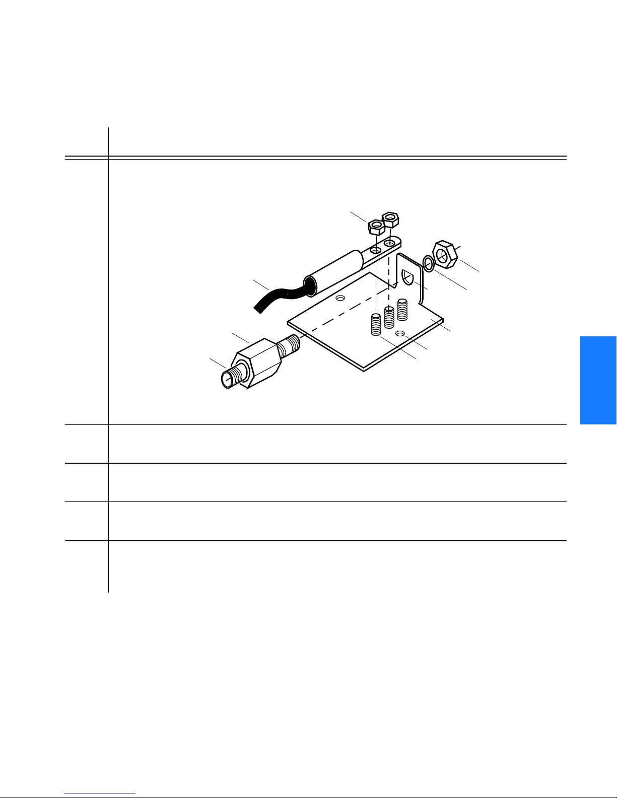
SSSSSSSSSSSS SSSSSSSSSS SSSSSSS
Procedure B. Roof Antenna Mounting and Cable Connection (cont’d)
Step Procedure
5 Slide the longer bolt of the lightning suppressor through the D-hole, and attach
with a nut and a washer (provided).
KEPS nut (2)
6 AWG (4.115 mm)
ground wire
D-hole
Nut
Washer
1
Lightningsuppressor
Cable connector (2)
Threaded posts (3)
(use any 2)
6 Install 1 in. nonmetallic conduit from the antenna to the lightning suppressor, and
from the lightning suppressor to the cable entrance into the building.
7 Install a user-supplied bracket, preferably non-metallic, to support the vertical
section of conduit to the antenna.
8 Connect a cable to the antenna, route the cable through the conduit, and
connect the cable to the lightning suppressor.
9 Connect a cable to the lightning suppressor, route the cable through the conduit
into the building, and route the cable through the building to the
TimeSource 3500 Shelf location.
Mounting plate
Hole for mounting bolt (2)
3
4
5
TimeSource 3500 91
Installation
097-72050-01 Issue 7: August 2003
Page 92

SSSSSSSSSSSS SSSSSSSSSS SSSSSSS
Procedure B. Roof Antenna Mounting and Cable Connection (cont’d)
Step Procedure
10 If the lightning suppressor was not mounted directly to a valid earth ground, crimp
a length of 6 AWG (4.115 mm) ground cable to the two-hole terminal, slide the
terminal over two of the three threaded posts on the lightning suppressor mounting
plate, and attach the terminal to the mounting plate with two KEPS nuts. Use the
two posts that allow the least bending of the 6 AWG (4.115 mm) ground cable.
11 Attach the other end of the cable to a valid earth ground.
12 Install fire-stopping material in all holes opened in the roof and/or walls during
this procedure.
13 Check all connections for tightness to prevent arcing and intermittent operation.
14 Coat all exposed connectors with an electrically conductive antioxidant
compound (e.g., Kopr-Shield spray).
3
End of Procedure
92 TimeSource 3500
097-72050-01 Issue 7: August 2003
Installation
Page 93

SSSSSSSSSSSS SSSSSSSSSS SSSSSSS
Mechanical Window Antenna
Installation procedures are to follow local company procedures
and the Installation Job Specification.
Prior to installing the antenna, the site, antenna location, cable
route, and all other details should have been planned.
For best results, choose a window facing the equator (facing south
in the northern hemisphere, facing north in the southern
hemisphere), and with the fewest obstructions of the sky.
To install the antenna, refer to Figure 15 and perform
Procedure C.
1
3
TimeSource 3500 93
Installation
097-72050-01 Issue 7: August 2003
4
5
Page 94

SSSSSSSSSSSS SSSSSSSSSS SSSSSSS
Figure 15. Mechanical Window Antenna-to-Shelf Cabling
3
Components of
990-72050-97
antenna
assembly
(Attached to cable, and on shelf)
Antenna
Antenna-to-IF cable
IF Converter
TNC Connector
(on IF converter)
TNC Connector
(Attached to cable)
TNC Connector
Antenna Assembly
990-72050-97
IF-to-shelf cable
RG-59/U Cable
060-72010-xx
(10 feet to 1,000 feet) or
Mini RG-59 Cable
060-72050-xx
(50 feet to 500 feet)
TimeSource 3500 Shelf
94 TimeSource 3500
097-72050-01 Issue 7: August 2003
Installation
Page 95

SSSSSSSSSSSS SSSSSSSSSS SSSSSSS
Procedure C. Mechanical Window Antenna Mounting and Cable Connection
Step Procedure
Prerequisite:
Observe all guidelines, considerations, Dangers, Warnings, Cautions, and Notes in the
Engineering and Ordering chapter.
Symmetricom Parts:
• Mechanical Window Antenna (990-72050-97)
• A length of RG-59/U plenum-rated coaxial cable (060-72010-xx), or
• A length of Mini RG-59/U plenum-rated coaxial cable (060-72050-xx)
User-Supplied Materials:
• Drill with bit of appropriate size and type to make pilot holes for the mounting screws
• Two screws of appropriate size and type to attach the foot of the mechanical chassis
to a window sill or wall near a window
•Screwdriver
• Cable ties or other method of securing cable
• GPS handheld receiver, personal computer with GPS location software, or other
method of determining latitude, longitude, and altitude
1 At the window chosen in Chapter 2, Engineering and Ordering, attach the base
of the mechanical window antenna to the chosen location (sill, wall, etc.) using
user-supplied screws (Figure 16).
1
3
2 Use the pivots on the mechanical window antenna to place the antenna section
flat against the window.
3 Tighten the pivot screws to secure the antenna (Figure 17).
4 Connect the antenna cable to the IF downconverter on the mechanical window
antenna assembly and route the cable to the TimeSource 3500 Shelf location.
5 Secure the cable using local company procedures.
6 Check all connections for tightness to prevent intermittent operation.
End of Procedure
TimeSource 3500 95
Installation
097-72050-01 Issue 7: August 2003
4
5
Page 96

SSSSSSSSSSSS SSSSSSSSSS SSSSSSS
Figure 16. Attaching the Mechanical Window Antenna
Use 2 user-supplied
screws to attach to wall
or window sill
Figure 17. Mechanical Window Antenna Pivot Screws
3
Place the antenna
against the window by
moving the chassis on
these pivots.
Tighten these pivot screws
to lock antenna position.
96 TimeSource 3500
097-72050-01 Issue 7: August 2003
Installation
Page 97
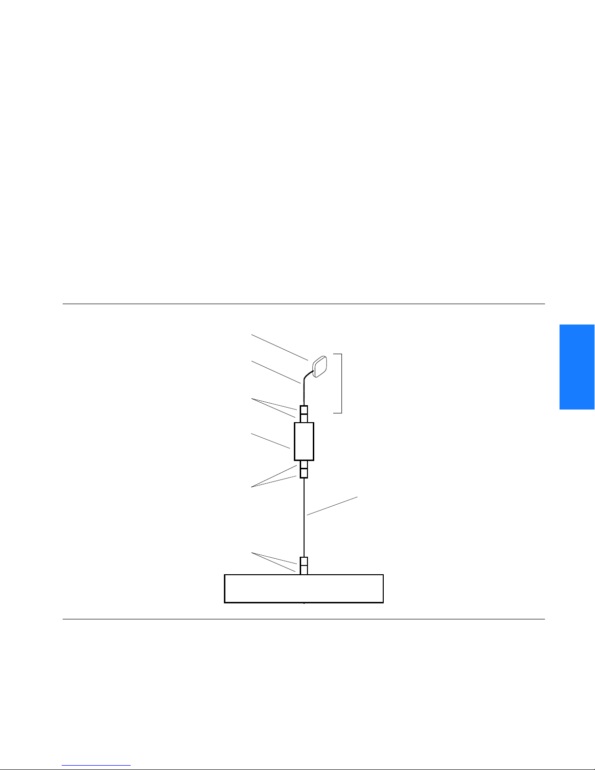
SSSSSSSSSSSS SSSSSSSSSS SSSSSSS
Self-Adhesive Window Antenna
Prior to installing the antenna, the site, antenna location, cable
route, and all other details should have been planned.
Installation procedures are to follow local company procedures
and the Installation Job Specification.
For best results, choose a window facing the equator (facing south
in the northern hemisphere, facing north in the southern
hemisphere), and with the fewest obstructions of the sky.
To install the antenna, refer to Figure 18 and perform
Procedure D.
Figure 18. Self-Adhesive Window Antenna-to-Shelf Cabling
Antenna
090-71010-87
Antenna-to-IF cable (10 ft)
060-00062-01
SMA connector
(Attached to cable,
and on IF converter)
IF converter
090-72050-97
and Mounting Kit
TNC connector
(Attached to cable,
and on IF converter)
TNC Connector
(Attached to cable, and on shelf)
Antenna kit
990-72050-98
IF-to-shelf cable
RG-59/U Cable
060-72010-xx
(10 feet to 1,000 feet) or
Mini RG-59 Cable
060-72050-xx
(50 feet to 500 feet)
1
3
4
TimeSource 3500 97
Installation
097-72050-01 Issue 7: August 2003
TimeSource 3500 Shelf
5
Page 98

3
SSSSSSSSSSSS SSSSSSSSSS SSSSSSS
Procedure D. Self-Adhesive Window Antenna Mounting and Cable Connection
Step Procedure
Prerequisite:
Observe all guidelines, considerations, Dangers, Warnings, Cautions, and Notes in the
Engineering and Ordering chapter.
Symmetricom Parts:
• Self-Adhesive Window Antenna kit (990-72050-98)
• A length of RG-59/U plenum-rated coaxial cable (060-72010-xx), or
• A length of Mini RG-59/U plenum-rated coaxial cable (060-72050-xx)
User-Supplied Materials:
• Drill with bit of appropriate size and type to make pilot holes for the mounting screws
• Four screws of appropriate size and type to attach the IF converter to a wall or other
mounting surface
•Screwdriver
• GPS handheld receiver, personal computer with GPS location software, or other
method of determining latitude, longitude, and altitude
1 Peel off the backing of one of the self-adhesive hook-and-loop strips and stick the
strip to the antenna (Figure 19).
2 Attach the hook-and-loop side of the other strip to the hook-and-loop side of the
strip on the antenna.
3 Peel off the backing and stick the antenna to the position on the window selected
in Chapter 2, Engineering & Ordering.
4 Use user-supplied screws to mount the IF downconverter to a suitable wall or other
structure (Figure 20). Be sure the distance along the cable route between the IF
downconverter and the antenna is no more than 10 ft.
5 Route and connect the antenna cable to the antenna side of the IF
downconverter.
6 Connect a cable to the TimeSource 3500 shelf side of the IF downconverter and
route the cable to the shelf location.
7 Secure the cable using local company procedures.
98 TimeSource 3500
097-72050-01 Issue 7: August 2003
Installation
Page 99
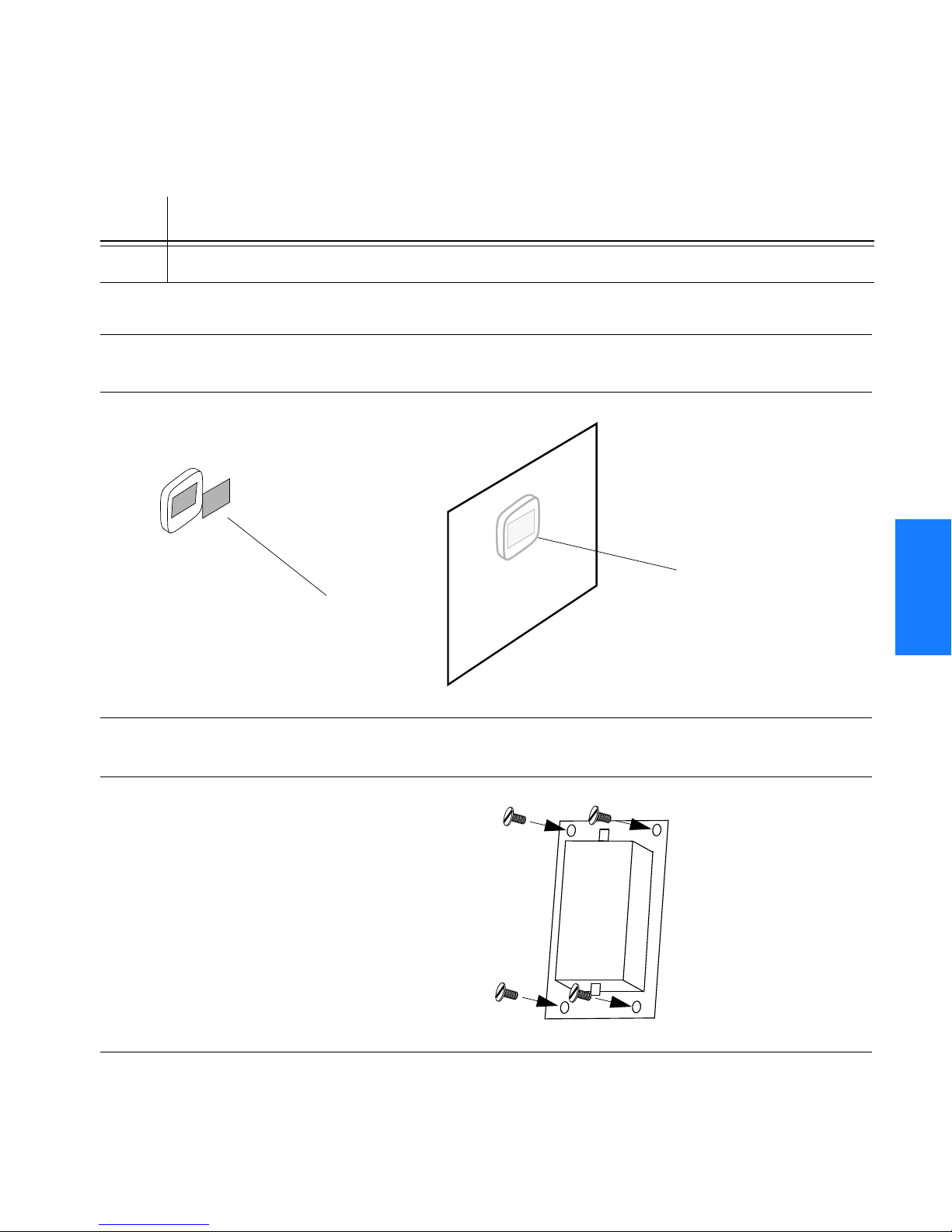
SSSSSSSSSSSS SSSSSSSSSS SSSSSSS
Procedure D. Self-Adhesive Window Antenna Mounting and Cable Connection (cont’d)
Step Procedure
8 Check all connections for tightness to prevent intermittent operation.
End of Procedure
Figure 19. Attaching the Self-Adhesive Window Antenna to a Window
Stick the
Attach the hook-and-
loop fabric pieces
together.
antenna to the
window.
1
3
Figure 20. Attaching the IF Converter
Use 4 user-supplied
screws to attach to a
wall or other structure.
TimeSource 3500 99
Installation
097-72050-01 Issue 7: August 2003
4
5
Page 100
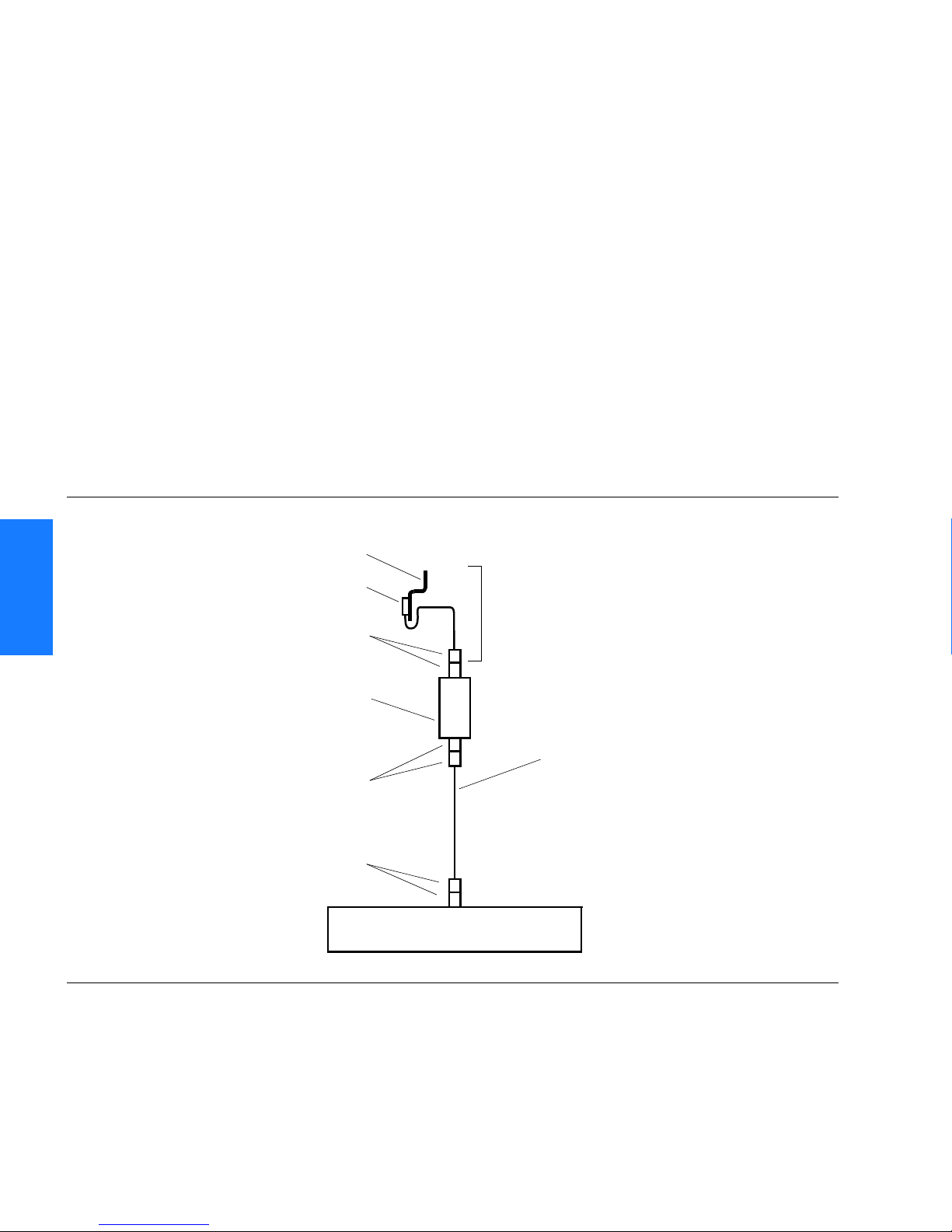
3
SSSSSSSSSSSS SSSSSSSSSS SSSSSSS
Wall Antenna
Prior to installing the antenna, the site, antenna location, cable
route, and all other details should have been planned.
Installation procedures are to follow local company procedures
and the Installation Job Specification.
For best results, choose a wall facing the equator (facing south in
the northern hemisphere, facing north in the southern
hemisphere), and with the fewest obstructions of the sky.
To mount the antenna through the wall, refer to Figure 21
and follow Procedure E.
Figure 21. Wall Antenna-to-Shelf Cabling
Antenna Mounting Bracket
070-00383-02
Antenna
112-00013-01
SMA connector
(Attached to cable,
and on IF converter)
Antenna kit
990-72050-95 (w/ 6’ antenna cable) or
990-72050-99 (w/19’ antenna cable)
IF converter
090-72050-97
and Mounting Kit
TNC connector
(Attached to cable,
and on IF converter)
TNC Connector
(Attached to cable, and on shelf)
TimeSource 3500 Shelf
IF-to-shelf cable
RG-59/U Cable
060-72010-xx
(10 feet to 1,000 feet) or
Mini RG-59 Cable
060-72050-xx
(50 feet to 500 feet)
100 TimeSource 3500
097-72050-01 Issue 7: August 2003
Installation
 Loading...