

Page 1

TimeSource 3600
GPS Primary Reference Source
097-72060-01
Issue 2
Page 2

FCC Regulatory Notice
Warning: This equipment generates, uses, and can radiate radio
frequency energy, and if not used in accordance with the instruction
manual, may cause interference to radio communications. It has
been tested and found to comply with the limits for a Class A
computing device pursuant to Subpart B of Part 15 of FCC rules,
which are designed to provide reasonable protection against such
interference when operated in a commercial environment. Operation
of this equipment in a residential area is likely to cause interference
in which case the user at his own expense will be required to take
whatever measures may be required to correct the interference.
Symmetricom, Inc.
2300 Orchard Parkway
San Jose, CA 95131-1017
http://www.symmetricom.com
Copyright © 1999–2001 Symmetricom, Inc.
All rights reserved. Printed in U.S.A.
Symmetricom is a registered trademark of Symmetricom, Inc. BesTime, DCD, and TimeSource are
trademarks of Symmetricom, Inc. All other product names, service marks, trademarks, and registered
trademarks used in this document are the proper ty of their respective owners.
2
TimeSource 3600
Page 3

Acronyms and Abbreviations
AIS alarm indication signal
E1 digital transmission (2.048 Mb/s)
ESD electrostatic discharge
ESF extended superframe
GPS Global Positioning System
LOS loss of signal
MDEV mean time deviation
pps pulse per second
PRS primary reference source
RO remote oscillator
SSM synchronization status messaging
TDEV time deviation
TOD time of day
UTC Universal Coordinated Time
Contents
3
Page 4

This page intentionally left blank.
4
TimeSource 3600
Page 5

Description
Chapter 1
Overview . . . . . . . . . . . . . . . . . . . . . . . . . . 18
Global Positioning System . . . . . . . . . . . . 19
Physical Description . . . . . . . . . . . . . . . . . 20
Roof Antenna . . . . . . . . . . . . . . . . . . . 22
Mechanical Window Antenna . . . . . . 23
Self-Adhesive Window Antenna . . . . 24
Wall Antenna . . . . . . . . . . . . . . . . . . . . 25
Functional Description . . . . . . . . . . . . . . . 26
Overview . . . . . . . . . . . . . . . . . . . . . . . 26
Antenna . . . . . . . . . . . . . . . . . . . . . . . . 28
IF Interface . . . . . . . . . . . . . . . . . . . . . . 28
GPS Receiver . . . . . . . . . . . . . . . . . . . . 28
Local Oscillator . . . . . . . . . . . . . . . . . . 28
Clock Extractors . . . . . . . . . . . . . . . . . 29
Power Supply . . . . . . . . . . . . . . . . . . . . 29
BesTime Ensemble Timing Generator 29
E1 or Analog Outputs . . . . . . . . . . . . 29
Eight Additional E1 or Analog Outputs
(990-72060-02 Systems Only) . . . 30
TOD Output . . . . . . . . . . . . . . . . . . . . 30
IRIG-B TOD Outputs
(990-72060-05 Systems Only) . . . 30
1 PPS Output . . . . . . . . . . . . . . . . . . . 30
Contents
5
Page 6

Description
Chapter 1
(cont’d)
10 MHz Output . . . . . . . . . . . . . . . . . 31
Two ESCIU Por ts
(990-72060-04 Systems Only) . . . 31
Alarm Interface . . . . . . . . . . . . . . . . . . 32
Communication Ports . . . . . . . . . . . . 32
Ethernet . . . . . . . . . . . . . . . . . . . . . . . . 32
Engineering &
Ordering
Chapter 2
Antenna Guidelines . . . . . . . . . . . . . . . . . 36
Roof Antenna Location and
Cabling Guidelines . . . . . . . . . . . . . 38
Roof Antenna Earth Ground Location
Guidelines . . . . . . . . . . . . . . . . . . . . 42
Roof Antenna Cable Choices . . . . . . 43
Window and Wall Antenna
Location Guidelines . . . . . . . . . . . . 45
Window and Wall Antenna
Cable Choices . . . . . . . . . . . . . . . . 47
IRIG-B TOD
(990-72060-05 System Only) . . . 48
RJ-422–to–RS-232 TOD Converter . 48
Shelf Considerations . . . . . . . . . . . . . . . . 49
Systems . . . . . . . . . . . . . . . . . . . . . . . . . . . 50
Standard System (Two T1 Outputs) 50
With Eight Additional E1 or
2.048 MHz Outputs . . . . . . . . . . . 51
6
TimeSource 3600
Page 7

Engineering &
Ordering
Chapter 2
(cont’d)
With Two E1 Synchronization
Insertion (ESCIU) Ports . . . . . . . . 51
With Four IRIG-B TOD Outputs . . . 52
Antennas . . . . . . . . . . . . . . . . . . . . . . . . . . 53
Roof Antenna . . . . . . . . . . . . . . . . . . . 53
Mechanical Window Antenna . . . . . . 53
Self-Adhesive Window Antenna . . . . 54
Wall Antenna . . . . . . . . . . . . . . . . . . . . 54
User-Supplied Tools and Materials . . . . . 55
For Roof Antenna Installation . . . . . . 55
For Mechanical Window Antenna
Installation . . . . . . . . . . . . . . . . . . . . 56
For Self-Adhesive Window Antenna
Installation . . . . . . . . . . . . . . . . . . . . 56
For Wall Antenna Installation . . . . . . 56
For Shelf Installation . . . . . . . . . . . . . . 57
Installation
Chapter 3
Outputs, Power, and Miscellaneous . 58
Unpacking . . . . . . . . . . . . . . . . . . . . . . . . . 60
Antenna . . . . . . . . . . . . . . . . . . . . . . . . . . . 61
Roof Antenna . . . . . . . . . . . . . . . . . . . 61
Mechanical Window Antenna . . . . . . 67
Self-Adhesive Window Antenna . . . . 70
Wall Antenna . . . . . . . . . . . . . . . . . . . . 73
Contents
7
Page 8

Installation
Chapter 3
(cont’d)
Rack Mounting . . . . . . . . . . . . . . . . . . . . . 77
Output Module Installation . . . . . . . . . . . 78
Power and Signal Cabling . . . . . . . . . . . . 80
Frame Ground . . . . . . . . . . . . . . . . . . . 82
Power . . . . . . . . . . . . . . . . . . . . . . . . . . 84
GPS Antenna . . . . . . . . . . . . . . . . . . . . 85
10 MHz Output . . . . . . . . . . . . . . . . . 85
E1 or Analog Synchronization
Outputs . . . . . . . . . . . . . . . . . . . . . . 86
Expansion Bus . . . . . . . . . . . . . . . . . . . 87
1 PPS Output . . . . . . . . . . . . . . . . . . . 87
E1 or Analog Reference Inputs . . . . . 88
Module for Additional E1 or
Analog Outputs
(990-72060-02 System Only) . . . 89
Module for IRIG-B TOD Outputs
(990-72060-05 System Only) . . . 90
Module for ESCIU Ports
(990-72060-04 System Only) . . . 91
Cutover Procedures for
Out-of-Service Equipment . . . 92
Cutover Procedures for
In-Service Equipment . . . . . . . . 94
Time of Day Output . . . . . . . . . . . . . 96
Ethernet . . . . . . . . . . . . . . . . . . . . . . . . 99
8
TimeSource 3600
Page 9

Installation
Chapter 3
(cont’d)
Communication Port 1 . . . . . . . . . . . 100
Communication Port 2 . . . . . . . . . . . 101
Alarms . . . . . . . . . . . . . . . . . . . . . . . . . 102
Craft Port . . . . . . . . . . . . . . . . . . . . . . . 103
Power-Up . . . . . . . . . . . . . . . . . . . . . . . . . . 104
Factory-Set Values . . . . . . . . . . . . . . . . . . 118
TL1 Reference
Chapter 4
Conventions . . . . . . . . . . . . . . . . . . . . . . . 122
Command Format . . . . . . . . . . . . . . . . . . 124
Response Format . . . . . . . . . . . . . . . . . . . 125
Parameters . . . . . . . . . . . . . . . . . . . . . . . . 127
Autonomous Messages . . . . . . . . . . . . . . 131
Report Alarm . . . . . . . . . . . . . . . . . . . 132
Report Event . . . . . . . . . . . . . . . . . . . . 133
Tasks/Commands . . . . . . . . . . . . . . . . . . . 134
Commands . . . . . . . . . . . . . . . . . . . . . . . . 136
Activate User . . . . . . . . . . . . . . . . . . . . 137
Cancel User . . . . . . . . . . . . . . . . . . . . . 138
Copy Memory . . . . . . . . . . . . . . . . . . . 139
Delete Equipment . . . . . . . . . . . . . . . . 142
Delete User Security . . . . . . . . . . . . . 143
Edit Communication . . . . . . . . . . . . . . 144
Edit Date . . . . . . . . . . . . . . . . . . . . . . . 148
Contents
9
Page 10

TL1 Reference
Chapter 4
(cont’d)
Edit Equipment . . . . . . . . . . . . . . . . . . 150
Enter Equipment . . . . . . . . . . . . . . . . . 158
Enter User Security . . . . . . . . . . . . . . . 160
Initialize Register . . . . . . . . . . . . . . . . . 161
Initialize System . . . . . . . . . . . . . . . . . . 162
Operate Alarm Cutoff All . . . . . . . . . 163
Retrieve Alarm All . . . . . . . . . . . . . . . 164
Retrieve Alarm Equipment . . . . . . . . 165
Retrieve Communication . . . . . . . . . . 167
Retrieve Condition All . . . . . . . . . . . . 170
Retrieve Condition Equipment . . . . . 171
Retrieve Equipment . . . . . . . . . . . . . . 173
Retrieve GPS Status . . . . . . . . . . . . . . 180
Retrieve Inventory . . . . . . . . . . . . . . . 182
Retrieve Performance Monitoring . . 184
Troubleshooting
Chapter 5
10
TimeSource 3600
Retrieve User Security . . . . . . . . . . . . 200
Set Source Identifier . . . . . . . . . . . . . . 201
Troubleshooting with Front Panel Items 204
Troubleshooting with Error Messages . . 209
Card Replacement . . . . . . . . . . . . . . . . . . 216
Repair and Return . . . . . . . . . . . . . . . . . . 218
Technical Assistance . . . . . . . . . . . . . . . . . 220
Page 11

Troubleshooting
Chapter 5
(cont’d)
Sales . . . . . . . . . . . . . . . . . . . . . . . . . . . . . . 221
Manual Updates . . . . . . . . . . . . . . . . . . . . 222
Specifications
Chapter 6
Antenna . . . . . . . . . . . . . . . . . . . . . . . . 224
Roof Antenna . . . . . . . . . . . . . . . . . 224
Mechanical Window Antenna . . . 224
Wall Antenna . . . . . . . . . . . . . . . . . 225
Self-Adhesive Antenna . . . . . . . . . 225
Communication Ports . . . . . . . . . . . . 226
Port 1 . . . . . . . . . . . . . . . . . . . . . . . 226
Port 2 . . . . . . . . . . . . . . . . . . . . . . . 227
Craft Port . . . . . . . . . . . . . . . . . . . . 228
Ethernet Port . . . . . . . . . . . . . . . . . . . . 229
Time of Day Outputs . . . . . . . . . . . . . 230
Network Time Protocol (NTP),vt
Type 4, Format 2 Driver Format 230
Cisco Systems Format . . . . . . . . . . 231
IRIG-B TOD Outputs
(990-72060-05 System Only) . 232
E1 Inputs . . . . . . . . . . . . . . . . . . . . . . . 233
Analog 2.048 MHz Inputs . . . . . . . . . 234
1 PPS Output . . . . . . . . . . . . . . . . . . . 235
E1 Outputs . . . . . . . . . . . . . . . . . . . . . 236
Standard . . . . . . . . . . . . . . . . . . . . . 236
Contents
11
Page 12

Specifications
Chapter 6
(cont’d)
Additional E1 Outputs
(990-72060-02 System Only) . 238
Analog 2.048 MHz Outputs . . . . . . . 240
Standard . . . . . . . . . . . . . . . . . . . . . 240
Additional Analog Outputs
(990-72060-02 System Only) . 241
10 MHz Output . . . . . . . . . . . . . . . . . 242
ESCIU Ports
(990-72060-04 System Only) . . . 243
Office Alarms . . . . . . . . . . . . . . . . . . . . 244
Connector Panel Contacts . . . . . . 244
Front Panel Lamps . . . . . . . . . . . . . 244
Front Panel Control . . . . . . . . . . . . 244
Power . . . . . . . . . . . . . . . . . . . . . . . . . . 245
Shelf Mechanical . . . . . . . . . . . . . . . . . 245
Shelf Environmental . . . . . . . . . . . . . . 246
Index
Figures
12
TimeSource 3600
1. Shelf . . . . . . . . . . . . . . . . . . . . . . . . . . . . 21
2. Roof Antenna . . . . . . . . . . . . . . . . . . . . 22
3. Mechanical Window Antenna . . . . . . 23
4. Self-Adhesive Window Antenna . . . . 24
5. Wall Antenna . . . . . . . . . . . . . . . . . . . . 25
Page 13

Figures
(cont’d)
6. Block Diagram . . . . . . . . . . . . . . . . . . . 27
7. ESCIU Signals . . . . . . . . . . . . . . . . . . . . 32
8. Antenna Field of View . . . . . . . . . . . . . 39
9. Antenna Location Examples . . . . . . . . 40
10. Sample Rooftop Antenna Mount . . 42
11. Antenna Mask Angle . . . . . . . . . . . . . 46
12. Rack Mounting Options . . . . . . . . . . 49
13. Roof Antenna-to-Shelf Cabling . . . . 62
14. Mechanical Window Antenna-to-Shelf
Cabling . . . . . . . . . . . . . . . . . . . . . . . . 67
15. Attaching the Mechanical Window
Antenna . . . . . . . . . . . . . . . . . . . . . . . 69
16. Mechanical Window Antenna Pivot
Screw . . . . . . . . . . . . . . . . . . . . . . . . . 69
17. Self-Adhesive Window Antenna-to-Shelf
Cabling . . . . . . . . . . . . . . . . . . . . . . . . 70
18. Attaching the IF Converter . . . . . . . 72
19. Wall Antenna-to-Shelf Cabling . . . . . 73
20. Hole Spacing . . . . . . . . . . . . . . . . . . . . 75
21. Wall Antenna Mounting . . . . . . . . . . 76
22. Rack Mounting Options . . . . . . . . . . 77
23. Options I/O Connector . . . . . . . . . . 79
24. Connector Panel and Front Panel
Connectors . . . . . . . . . . . . . . . . . . . . 81
Contents
13
Page 14

Figures
(cont’d)
25. Connector Panel Terminal Block
Connections . . . . . . . . . . . . . . . . . . . 82
26. E1 or Analog Output Wire-Wrap
Connections . . . . . . . . . . . . . . . . . . . 86
27. E1 or Analog Input Wire-Wrap
Connections . . . . . . . . . . . . . . . . . . . 88
28. Eight E1 or Analog Outputs
Connections . . . . . . . . . . . . . . . . . . . 89
29. IRIG-B TOD Output Connections . 90
30. Connector Layout of ESCIU Modules 91
31. ESCIU Cutover without Jacks
(Out-of-Service) . . . . . . . . . . . . . . . 93
32. ESCIU Cutover with Jacks
(In-Service) . . . . . . . . . . . . . . . . . . . . 95
33. RS-422–to–RS-232 TOD Converter
Mounting Plate . . . . . . . . . . . . . . . . . 97
34. RS-422–to–RS-232 TOD Converter
Connections . . . . . . . . . . . . . . . . . . . 98
14
35. Alarm Connections . . . . . . . . . . . . . . 102
36. Command Format . . . . . . . . . . . . . . . 124
37. Completed Response Format . . . . . 125
38. Deny Response Format . . . . . . . . . . 126
39. Controls and Indicators . . . . . . . . . . 205
40. Front of Shelf . . . . . . . . . . . . . . . . . . . 217
TimeSource 3600
Page 15

Ta b l e s
A. Timing Source Characteristics . . . . . . 27
B. TOD Connector Pinouts . . . . . . . . . . 96
C. Converter DB-25 Connector Pinouts 98
D. Ethernet 10base-T RJ-45 Connector
Pinouts . . . . . . . . . . . . . . . . . . . . . . . . 99
E. COM1 Connector Pinouts . . . . . . . . . 100
F. COM2 Connector Pinouts . . . . . . . . . 101
G. Craft Terminal Connector Pinouts . . 103
H. Parameter Factor y Settings . . . . . . . . 118
I. Parameter Definitions . . . . . . . . . . . . . . 127
J. Commands for Tasks . . . . . . . . . . . . . . . 134
K. Front Panel Items . . . . . . . . . . . . . . . . . 206
L. Message Troubleshooting . . . . . . . . . . 209
Contents
15
Page 16

This page intentionally left blank.
16
TimeSource 3600
Page 17

Description
This chapter provides an overview of the
global positioning system, and a physical
and functional description.
Chapter
Chapter
1
Page 18

SSSSSSSSSSSS SSSSSSSSSS SSSSSSS
Overview
The TimeSource 3600 is a Primary Reference Source (PRS) that
receives and processes signals from GPS satellites, and outputs
Stratum 1 synchronization signals traceable to UTC. TimeSource
3600 applications include synchronization for central offices,
wireless base stations, transmission nodes, and other cases where
a primary reference source can improve the performance of a
telecommunications network infrastructure.
The TimeSource 3600 is also ideal for installation in environments
where receiving GPS signals is difficult. Examples of environments
hostile to GPS signals include urban canyons which have a very
limited view of the sky because of blockage from nearby buildings,
and high interference zones where GPS signals are jammed by
competing over-the-air signals.
The TimeSource 3600 creates timing outputs by ensembling
signals from several sources. The sources include GPS signals, an
onboard rubidium local oscillator, and optional E1 or analog.
Timing outputs created from the ensemble are composed of the
most stable and least noisy parts of each input. The performance
of the E1 sources can be monitored and classified using standard
measures. Synchronization outputs are delivered in a framed, allones, E1 format or 2.048 MHz analog signal, a 10 MHz signal, a 1
pps signal, and a choice of time of day (TOD) formats.
18
The TimeSource 3600 minimizes timing impairments, such as
jitter and wander, that are created by network and transmission
systems. The synchronization timing is traceable to the GPS,
which provides the highest level of synchronization for telephony
networks. The TimeSource 3600 with its GPS input is a standalone office PRS. With the optional inputs ensembled, holdover is
extended if GPS signals are disrupted.
TimeSource 3600
Page 19

SSSSSSSSSSSS SSSSSSSSSS SSSSSSS
Global Positioning System
The United States Government developed the GPS navigation
system. It is a satellite-based, radio navigation aid designed to
provide global, all-weather, precise navigation and timing
capability to users 24 hours a day.
The satellites, circling the earth at approximately 20,197 km, are
arranged in 6 orbits with 4 operational satellites in each orbit.
Each satellite has an orbital period of approximately 12 hours.
This configuration assures that a minimum of 4 satellites, and as
many as 12, are in view anywhere in the world at all times.
The TimeSource 3600 tracks all satellites within its field of view.
The performance of each tracked satellite is observed and
compared to the others, and available for use in the timing
solution. A satellite with unacceptable performance data is
dropped from the timing solution.
GPS antennas must have line-of-sight access to the transmitting
satellites. Any structure that interferes with, or blocks, the view of
the satellites disrupts the reception of the signals, and can
adversely impact the timing performance of a receiver.
The TimeSource 3600 bridges frequent GPS outage periods with
BesTime algorithms, its ultra-stable Rubidium local oscillator and
advanced holdover technology. The technology anticipates the
outages and uses BesTime-generated predictor values to optimize
the performance of timing without direct satellite input.
1
2
3
4
Description
5
19
Page 20

SSSSSSSSSSSS SSSSSSSSSS SSSSSSS
Physical Description
The TimeSource 3600 consists of a shelf, plug-in card, antenna,
cables, hardware, and software. Optional system configurations
include eight additional E1 or analog outputs, two E1
synchronous clock insertion unit (ESCIU) ports, or four IRIG-B
TOD timing outputs.
The shelf (Figure 1) can be mounted in a 48 cm rack or an ETSI
53.5 cm rack. Other than a communications connector on the
front panel, all connectors are at the connector panel.
Four types of antennas are available:
• roof antenna for installation outdoors, usually on a roof
• mechanical antenna for installation indoors, mounted on a
window sill or wall for reception through a window
• self-adhesive antenna for installation indoors, adhered directly
to a window
20
• wall antenna for installation outdoors, through a hole in the wall
TimeSource 3600
Page 21

SSSSSSSSSSSS SSSSSSSSSS SSSSSSS
Figure 1. Shelf
22 cm
43.8 cm
990-72060-01, -02, -05 Systems
1
2
8.2 cm
3
22 cm
43.8 cm
990-72060-04 Systems
Description
4
8.2 cm
5
21
Page 22

SSSSSSSSSSSS SSSSSSSSSS SSSSSSS
Roof Antenna
The roof antenna (Figure 2) is encased in weather-resistant plastic
housing for outdoor installation, usually on a roof. A single coaxial
cable carries signals and power between the antenna and the
shelf.
Figure 2. Roof Antenna
31.4 cm
22
4.4
cm
TimeSource 3600
Page 23

SSSSSSSSSSSS SSSSSSSSSS SSSSSSS
Mechanical Window Antenna
The mechanical window antenna (Figure 3) may be attached to a
window sill or wall, in any position that allows the antenna to be
moved flush against the window. The antenna can be swung away
from the window for window maintenance, and returned to its
original position.
A single length of coaxial cable carries signals and power between
the antenna assembly and the shelf.
Figure 3. Mechanical Window Antenna
Coaxial Cable
Mounting Assembly
IF Converter
1
2
Antenna
3
43 cm
4
to TimeSource 3600 Shelf
Coaxial Cable
(not included with
antenna assembly)
Description
5
23
Page 24

SSSSSSSSSSSS SSSSSSSSSS SSSSSSS
Self-Adhesive Window Antenna
The self-adhesive window antenna assembly (Figure 4) consists of
the antenna and two pieces of self-stick hook-and-loop fabric
fasteners (Velcro brand or equivalent). The hook-and-loop fabric
attaches directly to a window. Coaxial cables carry signals and
power between the antenna and the IF converter, and between the
IF converter and the shelf.
Figure 4. Self-Adhesive Window Antenna
GPS WINDOW
ANTENNA
24
TimeSource 3600
Page 25

SSSSSSSSSSSS SSSSSSSSSS SSSSSSS
Wall Antenna
The wall antenna (Figure 5) is mounted on the outside of a
building wall. The antenna attaches magnetically to the mounting
bracket. The cable from the antenna is routed through a hole
drilled in the wall. Coaxial cables carry signals and power between
the antenna and the IF converter, and between the IF converter
and the shelf.
Figure 5. Wall Antenna
7.5 cm
1
2
Antenna Mounting Bracket
Antenna
3
Coaxial Cable
Description
4
5
25
Page 26

SSSSSSSSSSSS SSSSSSSSSS SSSSSSS
Functional Description
Overview
Figure 6 shows the main functions of the TimeSource 3600. The
center of the TimeSource 3600 is the BesTime Ensemble Timing
Generator, which uses the BesTime algorithm to analyze the phase
and frequency relationships, individually and collectively, of the
timing sources. Each type of timing source has a particular
characteristic that gives it an advantage over other sources, as
listed in Table A.
The BesTime algorithm uses the best characteristic of each source
to produce an output signal with greater overall accuracy and
stability than any single source. The contribution of a source is
based on its deviation from the weighted average of all the
sources. The more accurate a source, the more weight it has in the
final output. Every source is under constant evaluation and its
contribution subject to periodic adjustment. The output is
essentially the best performance of the best source.
26
TimeSource 3600
Page 27

SSSSSSSSSSSS SSSSSSSSSS SSSSSSS
Al
Figure 6. Block Diagram
arm
Interface
Alarms
1
Clock input & dc
power to antenna
Antenna
input
Optional source s
E1 Span
Input #1
E1 Span
Input #2
–48 V A
–48 V B
IF
Interface
Local
Oscillator
Clock
Extractor
Clock
Extractor
Power
Supply
Power to
shelf
Micro-
processor
BesTime
Ensemble
Timing
Generator
COM ports
Ethernet port
Status lamps
E1/analog output A
E1/analog output B
1 pps output
TOD output
10 MHz output
8 E1/analog
outputs
4 IRIG-B
TOD outputs
2 ESCIU ports
Optional ports
2
3
4
Table A. Timing Source Characteristics
Source Characteristic
Local Oscillator Short term stability
E1 Line Intermediate term stability
GPS Signal Long term stability
Description
5
27
Page 28

SSSSSSSSSSSS SSSSSSSSSS SSSSSSS
Antenna
The antenna types include a roof antenna, mechanical window
antenna, self-adhesive window antenna, or wall antenna. All
antennas include a GPS receiver, amplifier, and intermediatefrequency (IF) downconverter.
The GPS Receiver extracts a clock signal from the GPS satellite
signals. The receiver can process the signals from all satellites in
view, while simultaneously using the Earth location of the receiver
and other factors to determine an accurate clock signal.
The downconverter converts the L1-band GPS signal to IF for
long-distance transport on the coaxial antenna cable. The antenna
cable provides current from the shelf to the antenna, and
transports GPS satellite IF signals from the antenna to the shelf.
IF Interface
An IF interface accepts the signals from the antenna/IF converter,
and provides the clock information to the BesTime Ensemble
Timing Generator.
28
GPS Receiver
The GPS Receiver continuously tracks up to eight satellites, using both
carrier and code lock. The recovered pseudo-range measurement data
is processed to determine precise time and frequency state estimates
for the local oscillator. The receiver software is optimized to track and
update state estimates, when as few as one satellite is in view.
Local Oscillator
A rubidium oscillator, based on a digitally controlled servo-loop,
provides an ultra-stable local oscillator signal, which is sent to the
BesTime Ensemble Timing Generator.
TimeSource 3600
Page 29

SSSSSSSSSSSS SSSSSSSSSS SSSSSSS
Clock Extractors
A clock extractor circuit extracts a timing signal from each
external reference source. (External sources, other than the GPS
antenna, are optional.) The extracted timing signal is sent to the
BesTime Ensemble Timing Generator.
Power Supply
A power converter filters and converts –48 volts dc power supplied
to the shelf into the voltages required by the circuitry.
BesTime Ensemble Timing Generator
Clock signals from the GPS antenna (via the IF interface), local
oscillator, and two optional E1 span lines are used as sources by
the BesTime algorithms in the BesTime Ensemble Timing
Generator. The signals are analyzed for MDEV, TDEV, and other
phase and frequency characteristics.
The BesTime Ensemble Timing Generator uses mathematical
models to analyze each clock. The ensemble algorithms use the
comparisons and analyses to generate a highly stable timing
signal, which uses the best qualities of all inputs.
1
2
3
4
E1 or Analog Outputs
The BesTime Ensemble Timing Generator provides the timing for
the E1 or analog (2.048 MHz) timing signal available at the E1
OUT A and B connectors. E1 is provided in a framed, all-ones
format, which can be set to CAS, CAS4, CCS, or CCS4 framing.
2.048 MHz is provided in accordance with G.703/10.
Description
5
29
Page 30

SSSSSSSSSSSS SSSSSSSSSS SSSSSSS
Eight Additional E1 or Analog Outputs (990-72060-02 Systems Only)
This option provides a module for eight additional E1 or analog
(2.048 MHz) outputs. The module mounts in the OP TIONS I/O
mountings on the connector panel. These outputs function the
same as the standard E1 outputs.
TOD Output
The BesTime Ensemble Timing Generator provides the timing for
the TOD timing signal available at the RJ-45 connector, which
provides time code to devices compatible with NTP Type 4 or Cisco
format.
IRIG-B TOD Outputs (990-72060-05 Systems Only)
This option provides a module for four additional TOD outputs in
IRIG-B format. The module mounts in the OPTIONS I/O
mountings on the connector panel.
30
The BesTime Ensemble Timing Generator provides the timing for
the TOD timing signal, which provides timing code to devices
compatible with IRIG-B.
1 PPS Output
The BesTime Ensemble Timing Generator provides the timing for
the 1 pulse-per-second timing signal available at the 1 PPS
connector, which can be used for application-specific
requirements. This signal is not squelched during an alarm.
TimeSource 3600
Page 31

SSSSSSSSSSSS SSSSSSSSSS SSSSSSS
10 MHz Output
The BesTime Ensemble Timing Generator provides timing for the
10 MHz timing signal available at the 10 MHZ connector, which
can be used for local cellular frequency or testing purposes. This
signal is not squelched during an alarm.
Tw o E S C I U Po r t s (990-72060-04 Systems Only)
This option provides a module for two E1 ports. The module
mounts in the OPTIONS I/O mountings on the connector panel.
E1 traffic-carrying signals are synchronized using the Bestime
ensemble timing generator. Jitter and wander are also removed
before sending the E1 signals to network elements.
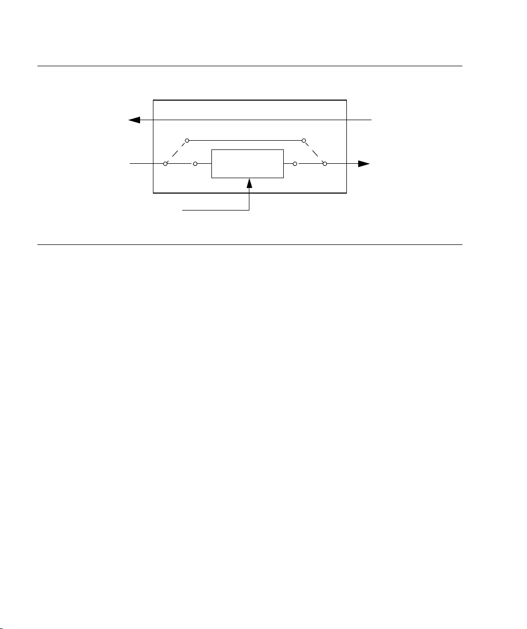
If an alarm condition or power failure occurs, relays allow the E1
signals to bypass the system. (See Figure 7.)
1
2
3
Description
4
5
31
Page 32
SSSSSSSSSSSS SSSSSSSSSS SSSSSSS
Figure 7. ESCIU Signals
ESCIU
Pass-through in Return Direction
Relay Bypass Path
Datastream
Synchronizer
BesTime Ensemble
Timing Generator
Synchronizing signal
Alarm Interface
The microprocessor delivers alarms to normally open dry-contact
type connections. Alarms are also indicated by the front-panel
status lamps.
32
Communication Ports
Three serial communication ports carry TL1 commands,
responses, and autonomous messages between the TimeSource
3600 and an external terminal.
Ethernet
The TimeSource 3600 has six Ethernet ports to carry TL1
commands, responses, and autonomous messages between the
TimeSource 3600 and an external terminal, or an Element
Manager, or both. The user can configure the IP address, subnet
mask, and gateway address for the Ethernet ports.
TimeSource 3600
Page 33

SSSSSSSSSSSS SSSSSSSSSS SSSSSSS
Four ports (5001, 5002, 5003, and 5004) are configured to act as
though a serial-port communication terminal were connected to
them. These ports communicate TL1 commands, responses and
autonomous messages.
Two additional ports communicate with Element Managers, which
may have NMS, OSMF, or similar software. An Element Manager
establishes a connection with one port (5551) for TL1 commands
and responses. Another port (5550) establishes a connection to an
Element Manager, sends autonomous messages, and closes the
connection when finished.
1
2
3
Description
4
5
33
Page 34

SSSSSSSSSSSS SSSSSSSSSS SSSSSSS
This page intentionally left blank.
34
TimeSource 3600
Page 35

Engineering & Ordering
This chapter provides information to assist
in planning the installation and ordering a
system appropriate for a specific site.
Chapter
2
Page 36

SSSSSSSSSSSS SSSSSSSSSS SSSSSSS
Antenna Guidelines
Perform a site survey as described in Procedure A before ordering
the system. Use the guidelines and considerations in the Roof
Antenna Location and Cabling Guidelines section and the Shelf
Considerations section.
36
TimeSource 3600
Page 37

SSSSSSSSSSSS SSSSSSSSSS SSSSSSS
Procedure A. Site Survey
Step Action
1
Determine the shelf location.
2 Determine the best location for mounting the antenna (less than 330 m of cable
from the shelf). Use the guidelines and considerations in the Roof Antenna Location
and Cabling Guidelines section.
3 If a roof-mounted antenna is installed, determine the location of the grounding point
for the lightning suppressor, then determine the location of the lightning suppressor.
The cable length between the lightning suppressor and the grounding point must be
less than 4.6 m. If the grounding point is inside the building, the cable length between
the grounding point and the cable entry must be less than 15 m. Valid lightning
suppressor grounding points are:
• Valid ring ground system (usually for roof-mounted lightning suppressors)
• Structural steel of building (for interior-mounted or exterior-mounted lightning
suppressors, attach with a cad weld)
• Central Office ground plate (usually for interior-mounted lightning suppressors)
4 If a roof-mounted antenna is installed, two lengths of cable are required. Plan the
cable route and measure the length of cable required between the antenna and the
lightning suppressor, and between the lightning suppressor and the shelf.
2
2
3
5 If a window or wall-mounted antenna is installed, plan the cable route and measure
the length of cable required between the antenna and the shelf.
6 Determine the two separate –48 V power sources for the shelf. If only one –48 V
power source is available, it must be cabled to both TimeSource 3600 power inputs.
End of Procedure
Engineering & Ordering
4
5
37
Page 38

SSSSSSSSSSSS SSSSSSSSSS SSSSSSS
Roof Antenna Location and Cabling Guidelines
DANGER:
electrical or physical hazard to work persons or equipment.
Avoid proximity to all high-voltage sources. Mount in an
easily maintainable location.
The ideal roof antenna location provides a clear, unobstructed
view of the sky from the zenith to the horizon line, and 360
degrees around the horizon.
A compromise often must be made between location and satellite field
of view. With a smaller the field of view, the TimeSource 3600 can use
fewer satellites in the solution for GPS derived time. The TimeSource
3600 will operate with an average of one satellite in view for 40% of the
time in a day.
Signals closer to the horizon are often subject to multipath effects,
which degrade the timing solution. The TimeSource 3600 can be
set to ignore, or mask, all signals from the horizon up to a chosen
angle of elevation (mask angle). (See Figure 8.)
Do not select an antenna location that could be an
38
TimeSource 3600
Page 39

SSSSSSSSSSSS SSSSSSSSSS SSSSSSS
Figure 8. Antenna Field of View
Antenna position
Antenna
field of view
10°
Mask angle*
Horizon
Equator
* An angle of 10° masks objects up to about 1 m above the
horizon at 6 m from the antenna (illustration at right.)
Due to the geometry of the GPS satellite orbits, more satellites are
visible in the direction of the equator than the poles. If possible, place
the antenna so that the antenna has a clear view toward the equator
(toward the south in the northern hemisphere, or toward the north in
the southern hemisphere). Up to 60 degrees of arc, centered at the
pole, may be blocked with little effect in the temperate latitudes. This
note is less applicable in latitudes nearer the equator.
Obstructions
toward the pole
if possible
10°
Mask angle*
10°
6 m
Pole
1 m
2
2
3
4
The total of obstructions above the mask angle should not obscure
more than 25 percent of the total field of view (90 degrees of
azimuth) (Figure 9).
Engineering & Ordering
39
5
Page 40
SSSSSSSSSSSS SSSSSSSSSS SSSSSSS
Figure 9. Antenna Location Examples
Antenna tower
antenna
location
(Note 1)
Antenna
tower
Location A Location B
Notes:
1. Place the antenna high enough on the tower that obstructions are below the mask angle;
mount the antenna more than 1 meter away from the tower, and far below the interference
of the antennas at the top of the tower. Tower mounting is the least desirable location because of the potential for severe multipath, and difficulty in troubleshooting and maintenance.
2. Place the antenna high enough that the roof structure and tree are below the mask angle,
and the water tower does not block a large portion of the sky.
Water
tower
Building
antenna
location
(Note 2)
Tree
Roof
structure
40
No single obstruction should block a large portion (45 degrees of
azimuth) of the view.
The most important obstructions are within 400 meters of the
antenna. Obstructions may include, but are not limited to, towers,
buildings, other construction, trees, and high-voltage power lines.
Attempt to avoid locating the antenna within 30 degrees azimuth
of the transmission direction of any transmitting antenna in the
area, even if the transmitting antenna operates at a different
frequency. A transmitting antenna may cause the GPS antenna to
become overloaded and reduce its reception capabilities.
TimeSource 3600
Page 41

SSSSSSSSSSSS SSSSSSSSSS SSSSSSS
The minimum horizontal distance from other receiving antennas is
1 meter.
To reduce multipath signal distortions, the minimum horizontal
distance from vertical reflective structures (e.g., heating ducts,
equipment housings, etc.) is twice the height of the structure, and
no less than 3 meters (Figure 10).
Do not locate the antenna underneath high power lines. If this
cannot be avoided, ensure the antenna is placed at least twice as
far from the power line as the power line is high (to avoid danger
to personnel and multipath effects).
Cables must be run as straight as possible. All cables should be
routed in accordance with local company practices.
2
2
Note:
routed in accordance with local company practices.
Observe the following guidelines during the placement and
installation of the cables:
Warning:
Keep all impedances as low as possible. All cables should be
• Route cables as straight as possible (bends in the cable
increase impedance at lightning frequencies), in accordance
with local company practices.
• Any opening where conduit enters the building must be
waterproofed per local company practices.
• Treat all exposed connections with an electrically conductive
anti-corrosion compound (Kopr-Shield or equivalent).
Avoid small-radius turns and unnecessary turns.
3
4
5
Engineering & Ordering
41
Page 42

SSSSSSSSSSSS SSSSSSSSSS SSSSSSS
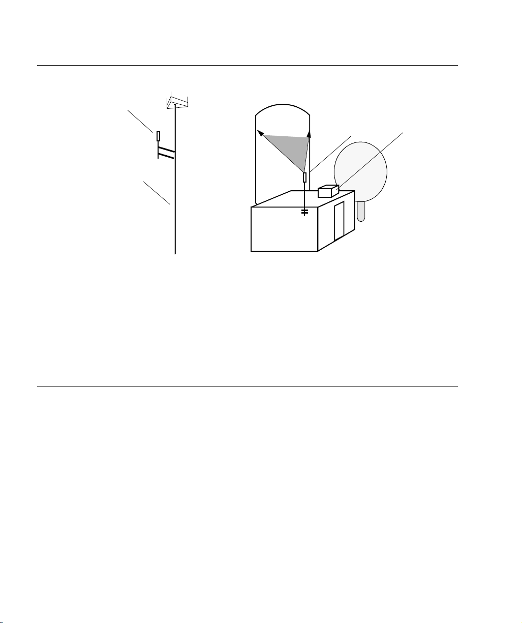
Figure 10. Sample Rooftop Antenna Mount
At or above the
level of the
Reflective
surface
reflective surface
Cable
conduit
2.4 m
Rooftop
Heating
Ducts
(twice the 2.4 m height)
4.8 m
(3 m minimum)
Cable entry
into building
Note: This is an example only. Not all parts are available from Symmetricom.
Antenna
Mounting
Bracket
Mounting Pipe
Pipe clamped
to wall
Building Wall
42
Roof Antenna Earth Ground Location Guidelines
The roof ring ground system, a Central Office grounding plate, and
building structural steel are examples of valid earth ground
points. If the mounting plate cannot be bolted to a valid earth
ground, or if the mounting plate is to be installed in a nonmetallic
junction box, bolt the mounting plate to a point within 4.6 meters
of the valid earth ground.
TimeSource 3600
Page 43

SSSSSSSSSSSS SSSSSSSSSS SSSSSSS
Roof Antenna Cable Choices
The antenna assembly uses the same coaxial cable for power and
antenna signals. The length of cable is determined by
circumstances of the installation and site.
Symmetricom offers RG-59/U plenum-rated coaxial cable (0.812
mm [20 AWG], 75 ohm coaxial) with male TNC connectors
attached, in the following lengths:
• 3 m cable (060-72010-01)
• 6 m cable (060-72010-02)
• 15 m cable (060-72010-05)
• 30 m cable (060-72010-10)
• 61 m cable (060-72010-20)
• 91 m cable (060-72010-30)
• 152 m cable (060-72010-50)
• 182 m cable (060-72010-60)
• 243 m cable (060-72010-80)
• 305 m cable (060-72010-99)
Two cables are required: one to connect the antenna to the
lightning suppressor, and another to connect the lightning
suppressor to the TimeSource 3600 Shelf.
Optionally, one length of coaxial cable may be ordered, which
must be cut and prepared with end-connectors at the point where
the suppressor is located.
2
2
3
4
Engineering & Ordering
5
43
Page 44

SSSSSSSSSSSS SSSSSSSSSS SSSSSSS
The following items, which must be ordered separately, are
available for this type of installation:
• TNC connector kit (093-72010-98) includes:
- TNC connectors for RG-59/U cables (8)
- Rubber boots (8)
- TNC adapter connectors (2)
• TNC crimp tool (154-00023-01)
44
TimeSource 3600
Page 45

SSSSSSSSSSSS SSSSSSSSSS SSSSSSS
Window and Wall Antenna Location Guidelines
When selecting a window or wall in which to install the antenna,
select the window or wall which has the maximum unobstructed
view of the sky. Do not select a window or wall which has the view
of the sky obstructed by trees, buildings, or towers. The smaller
the field of view, the fewer the number of satellites that can be
used in the timing solution for GPS derived time. The consequence
of this is that the timing generator may experience holdover more
often and may eventually go into alarm.
Due to the geometry of the GPS satellite orbits, more satellites are
visible in the direction of the equator than the poles. If possible,
select a window or wall which has a clear view toward the equator
(toward the south in the northern hemisphere, or toward the north
in the southern hemisphere). This guideline is less applicable in
latitudes nearer the equator and more important nearer the poles.
2
2
Certain parts of the sky are blocked from view. These obstructions
usually exist from the horizon line and up, for example, a building
or mountain. The processor inside the GPS receiver possesses
every piece of the sky, whether it is blocked or not. If unproductive
parts of the sky are masked from the processor’s view, the
processing time is reduced, and the timing solution can be
achieved more quickly.
Note:
view of the sky begins is called a mask angle. The mask angle typically should not exceed 10 degrees (if the mask angle is set too
high, too little of the sky is available to the receiver). Determine the
mask angle for the selected antenna location (Figure 11) and make
a note of it. The mask angle, in degrees, will be entered during the
initial setup.
A band of the sky from the horizon up to a point where a
Engineering & Ordering
45
3
4
5
Page 46

SSSSSSSSSSSS SSSSSSSSSS SSSSSSS
Figure 11. Antenna Mask Angle
TimeSource 3600
Antenna
1 m
6 m
Note: TimeSource 3600 does
not detect satellites in the
masked area.
*An angle of 10° masks objects up to about 1 m above the horizon at
6 m from the antenna.
10° mask angle*
46
TimeSource 3600
Page 47

SSSSSSSSSSSS SSSSSSSSSS SSSSSSS
Window and Wall Antenna Cable Choices
A window or wall antenna includes an attached coaxial cable
terminating in a male SMA connector.
A separate cable is required to connect the IF converter to the
TimeSource 3600 shelf. Two types of plenum-rated cable are available.
The cables with longer length capabilities (060-72010-xx) are
RG-59/U (0.812 mm [20 AWG], 75 ohm coaxial) with male TNC
connectors attached to each end. Assembled cables are available
in the following lengths:
• 3 m cable (060-72010-01)
• 6 m cable (060-72010-02)
• 15 m cable (060-72010-05)
• 30 m cable (060-72010-10)
• 61 m cable (060-72010-20)
• 91 m cable (060-72010-30)
2
2
3
• 152 m cable (060-72010-50)
• 182 m cable (060-72010-60)
• 243 m cable (060-72010-80)
• 305 m cable (060-72010-99)
The more flexible cables (060-72050-xx) are Mini RG-59/U
(0.812 mm [20 AWG], 75 ohm coaxial) with male TNC connectors
attached to each end. Assembled cables are available in the
following lengths:
• 15 m (060-72050-05)
• 30 m (060-72050-10)
• 61 m (060-72050-20)
• 152 m cable (060-72010-50)
Engineering & Ordering
47
4
5
Page 48

SSSSSSSSSSSS SSSSSSSSSS SSSSSSS
IRIG-B TOD (990-72060-05 System Only)
If using the IRIG-B TOD outputs (990-72060-05 TimeSource 3600
System), right-angle BNC connectors are provided to prevent small
radius turns in the IRIG-B TOD cables. The right-angle BNC
connectors may be attached to the IRIG-B BNC adapter (also
provided) BNC connectors, to direct the cables from the shelf as
desired.
For each IRIG-B TOD output, a user-supplied cable with BNC
connectors on each end is installed between the adapter and the
network elements requiring IRIG-B TOD timing.
RJ-422–to–RS-232 TOD Converter
If using time-of-day (TOD), and the device receiving the time code
accepts an RS-232 signal instead of an RS-422 signal (for
example, a Cisco router), an RJ-422–to–RJ-232 TOD Converter Kit
is required (ordered separately, part number 093-72000-98).
The RJ-422–to–RJ-232 TOD Converter Kit consists of a mounting
plate with a female RJ-45 connector, a female DB-25 connector, a
TOD converter, and two screws.
48
Install the converter anywhere (for example, on unused space on a
rack) within 305 cable meters of the TimeSource 3600 shelf, and
within 15 cable meters of the device receiving the time code.
The user must supply two cables. One cable is a Category 5 fourpair RS-422 cable, 305 meter maximum, with RJ-45 connectors
on each end. Route this cable between the TimeSource 3600 Shelf
and the converter.
The other cable is an RS-232 data communications cable, 15
meters maximum, with a 25-pin male D-type connector and
another connector determined by the device receiving the time
code. Route this cable between the converter and the device
receiving the time code.
TimeSource 3600
Page 49
SSSSSSSSSSSS SSSSSSSSSS SSSSSSS
Shelf Considerations
The TimeSource 3600 Shelf can be mounted in an ETSI 53.5 cm
rack or a 48 cm rack. The shelf is shipped with supplied mounting
ears positioned for flush mounting on an ETSI 53.5 cm rack.
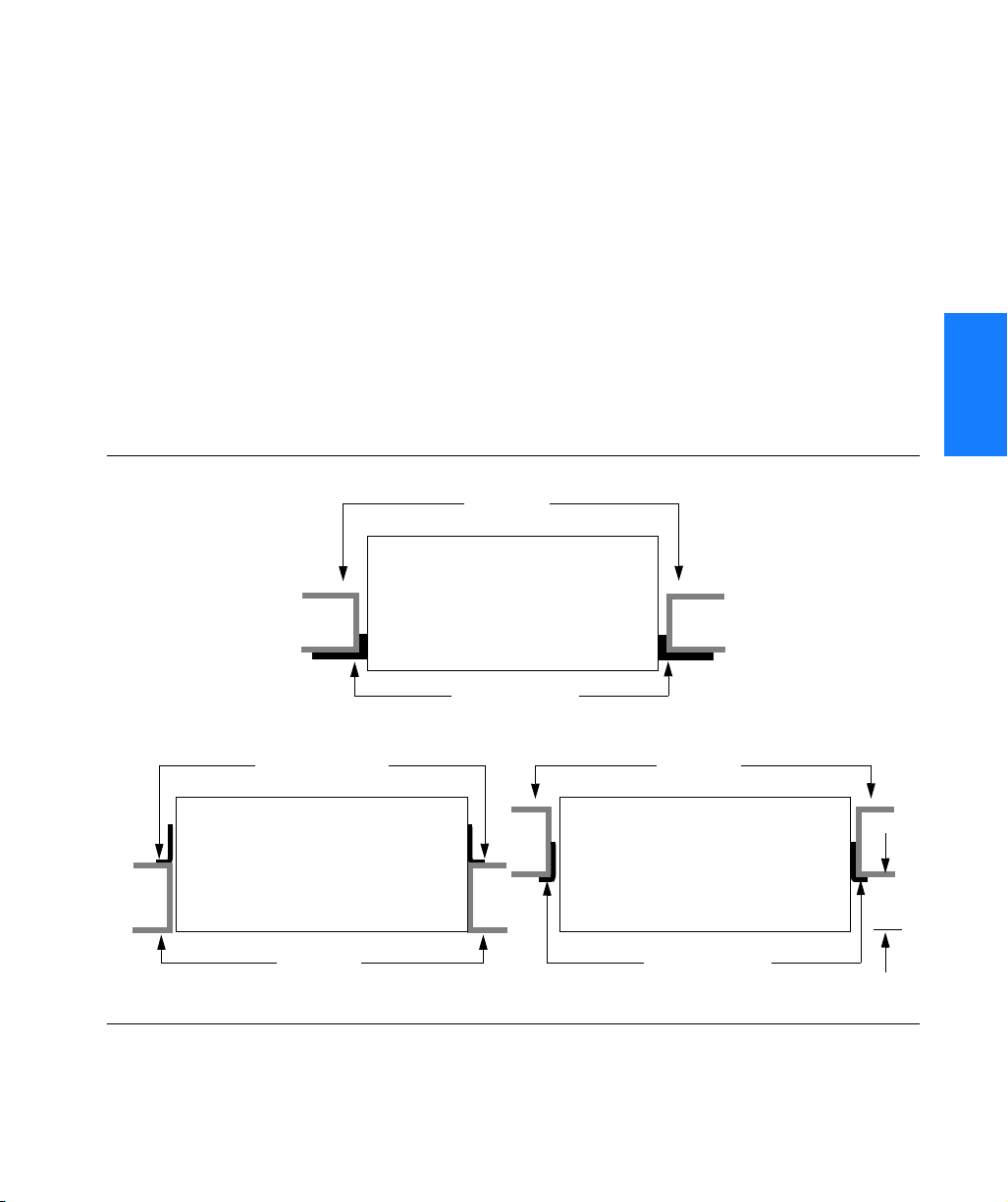
Attach the mounting ears, as shown in Figure 12, for flush
mounting or 12.7 cm offset mounting. Attach the long side of the
mounting ear to the shelf for an ETSI 53.5 cm rack, and attach
the short side of a mounting ear to the shelf for a 48 cm rack.
Mount the shelf in the rack according to standard company
practices.
Figure 12. Rack Mounting Options
Rack rails
Rear of rack
Top of shelf
2
2
3
A. ETSI – 53.5 cm rack
Mounting ears
Rear of rack
Top of shelf
Top of shelf
Rack rails Mounting ears
B. Flush mounting – 48 cm rack
Mounting ears
Rack rails
Rear of rack
Top of shelf
Top of shelf
C. 12.7 cm offset – 48 cm rack
Engineering & Ordering
4
12.7
cm
5
49
Page 50

SSSSSSSSSSSS SSSSSSSSSS SSSSSSS
Systems
The TimeSource 3600 Systems available are listed below. The
antenna must be ordered separately.
Standard System (Two E1 Outputs)
This system (990-72060-01) includes:
• TimeSource 3100 Shelf (090-72000-11)
• TimeSource 3600 card (090-72060-01)
• Hardware kit (093-72060-87)
• System software compact disc (CD) (992-72060-xx) Version
1.04.02 or higher
• TimeScan Craft software compact disc (CD) (992-46750-xx)
Version 7.0.1 or higher
• TimeScan Craft connection key (020-46700-001)
50
TimeSource 3600
Page 51

SSSSSSSSSSSS SSSSSSSSSS SSSSSSS
With Eight Additional E1 or 2.048 MHz Outputs
This system (990-72060-02) includes:
• TimeSource 3100 Shelf (090-72000-11)
• TimeSource 3600 card with additional E1 or 2.048 MHz
outputs (090-72060-02)
• Hardware kit (093-72060-87)
• System software compact disc (CD) (992-72060-xx) Version
1.04.02 or higher
• TimeScan Craft software compact disc (CD) (992-46750-xx)
Version 7.0.1 or higher
• TimeScan Craft connection key (020-46700-001)
With Two E1 Synchronization Insertion (ESCIU) Ports
This system (990-72060-04) includes:
• TimeSource 3100 Shelf (090-72000-11)
2
2
3
• TimeSource 3600 card with ESCIU ports (090-72060-04)
• Hardware kit (093-72060-87)
• System software compact disc (CD) (992-72060-xx) Version
1.04.02 or higher
• TimeScan Craft software compact disc (CD) (992-46750-xx)
Version 7.0.1 or higher
• TimeScan Craft connection key (020-46700-001)
Engineering & Ordering
4
5
51
Page 52

SSSSSSSSSSSS SSSSSSSSSS SSSSSSS
With Four IRIG-B TOD Outputs
This system (990-72060-05) includes:
• TimeSource 3100 Shelf (090-72000-11)
• TimeSource 3600 card with IRIG-B TOD outputs (090-72060-
05)
• Hardware kit (093-72060-87)
• System software compact disc (CD) (992-72060-xx) Version
1.04.02 or higher
• TimeScan Craft software compact disc (CD) (992-46750-xx)
Version 7.0.1 or higher
• TimeScan Craft connection key (020-46700-001)
52
TimeSource 3600
Page 53

SSSSSSSSSSSS SSSSSSSSSS SSSSSSS
Antennas
The antennas available are listed below. A TimeSource 3600
System must be ordered separately.
Roof Antenna
This antenna kit (990-72050-96) includes:
• IF antenna assembly (090-72010-97)
• Rooftop antenna installation kit (093-72050-96) includes:
- Antenna cable bracket kit (093-00001-01)
- Mounting bracket for surge suppressor (070-00300-02)
- Surge suppressor (143-00018-01)
- Miscellaneous installation parts
Mechanical Window Antenna
This antenna kit (990-72050-97) comes as a fully assembled
antenna with the following major components:
• Antenna, with cable and SMA connector attached (09072050-90)
• IF converter (090-72050-97)
• Mechanical chassis (074-72050-97)
2
2
3
4
Engineering & Ordering
5
53
Page 54

SSSSSSSSSSSS SSSSSSSSSS SSSSSSS
Self-Adhesive Window Antenna
This antenna kit (990-72050-98) includes:
• Antenna (090-72010-87)
• IF converter (090-72050-97)
• Self-adhesive window antenna installation kit (093-72050-98)
includes:
- RG316 cable, 3 m (060-00062-01)
- Cable tie mounts (128-00302-02) and
cable ties (128-00500-05)
Wall Antenna
This antenna kit (990-72050-99) includes:
• IF converter (090-72050-97)
54
• Wall antenna kit (093-72050-99) includes:
- Antenna, with 5.8 m of cable and SMA connector attached
(112-00013-01)
- Antenna mounting bracket (070-00413-01)
- Cable tie mounts (128-00302-02) and
cable ties (128-00500-05)
TimeSource 3600
Page 55

SSSSSSSSSSSS SSSSSSSSSS SSSSSSS
User-Supplied Tools and Materials
Ensure that the user-supplied tools and materials listed below are
on hand for installation, as applicable.
For Roof Antenna Installation
• 2.5 cm diameter galvanized metal pipe, used as a mast to
mount the antenna. Mast should be long enough to position
the antenna above any metal object on the roof
• Screws to attach the lightning suppressor mounting plate
• Plumb line or bubble level
• Nonmetallic junction box for lightning suppressor (optional if
lightning suppressor mounted indoors)
2
2
• 2.5 cm diameter PVC pipe as conduit for outdoor cables
• PVC fittings appropriate to the installation and cable route
• Appropriate tools and materials for cutting, shaping, and
connecting PVC pipe
• 4.115 mm (6 AWG) ground wire
• Spade lugs for 4.115 mm (6 AWG) ground wire
• Crimp tool for 4.115 mm (6 AWG) spade lugs
• Hardware to attach the ground wire to a valid earth ground
• Fire-stopping material to seal conduit hole in roof or wall
• Electrically conductive antioxidant compound (Kopr -Shield or
equivalent) to coat exposed connections to prevent oxidation
• Tool to cut cable, if installation requires custom lengths of cable
Engineering & Ordering
55
3
4
5
Page 56

SSSSSSSSSSSS SSSSSSSSSS SSSSSSS
For Mechanical Window Antenna Installation
• Drill with bit of appropriate size and type to make pilot holes
for the mounting screws
• 2 screws of appropriate size and type to attach the foot of the
mechanical chassis to a window sill or wall near a window.
• Screwdriver
• Cable ties or other method of securing cable
• GPS handheld receiver, personal computer with GPS location
software, or other method of determining latitude, longitude,
and altitude
For Self-Adhesive Window Antenna Installation
• Drill with bit of appropriate size and type to make pilot holes
for the mounting screws
• 4 screws of appropriate size and type to attach the IF
converter to a wall or other mounting surface.
56
• Screwdriver
• GPS handheld receiver, personal computer with GPS location
software, or other method of determining latitude, longitude,
and altitude
For Wall Antenna Installation
• Ladder, or safe method of reaching the antenna location on
the exterior wall
• Drill with bits of appropriate size and type to make pilot holes
for the antenna mounting bracket screws, and to make a
hole through the wall for the antenna cable
TimeSource 3600
Page 57

SSSSSSSSSSSS SSSSSSSSSS SSSSSSS
• 2 screws of appropriate size and type to attach the antenna
mounting bracket to an exterior wall.
• Screwdriver
• Electrically conductive antioxidant compound (Kopr-Shield
or equivalent) to coat exposed connections to prevent
oxidation
• Fire stopping material to seal the hole in the wall
• GPS handheld receiver, personal computer with GPS location
software, or other method of determining latitude, longitude,
and altitude
For Shelf Installation
• A Phillips-head screwdriver for installing the TimeSource
3600 Shelf in a rack
• Four screws to mount the shelf in a rack
2
2
3
Engineering & Ordering
4
5
57
Page 58

SSSSSSSSSSSS SSSSSSSSSS SSSSSSS
Outputs, Power, and Miscellaneous
• RG-58 coaxial cable for 1 PPS, 10 MHZ outputs
• Ethernet 10BaseT cable for Ethernet port
• Category 5 four-pair RS-422 cable, with RJ-45 connector for
the TOD output, RS-422–to–RS-232 TOD converter
• RS-232 cable with DB-25 connector for the RS-422–to–
RS-232 TOD converter
• RS-232 cable with DB-9 connector for COM2 port
• 4.115 mm (6 AWG) ground wire
• 1.47 mm (16 AWG) green insulated ground wire
• 1.47 mm (16 AWG) red insulated wire
• 1.47 mm (16 AWG) black insulated wire
58
TimeSource 3600
Page 59

Installation
This chapter is the sequential order of
procedures for installation and power-up.
Chapter
3
Page 60

SSSSSSSSSSSS SSSSSSSSSS SSSSSSS
Unpacking
Use the procedures in the order they appear in this chapter to
install the TimeSource 3600. If any difficulties are encountered
during the installation process, contact Symmetricom’s Customer
Technical Assistance Center (CTAC). Refer to the Technical
Assistance section of the Troubleshooting chapter for telephone
numbers.
CTAC includes Product Technical Support for technical
information, and Customer Service for information about an order,
RMAs, and other information.
Warning:
procedures regarding electrostatic discharge (ESD), including:
•Use grounded wrist straps connected to equipment frame
•Store cards only in antistatic packaging provided by the
Note:
packed in the original packing material. Contact Customer Service
if additional packaging is needed.
Unpack equipment carefully; check for completeness against the
purchase order. Notify Symmetricom if items are missing.
Inspect equipment for shipping damage, including bent or loose
hardware, and broken connectors.
If equipment was damaged in transit, contact Customer Service to
request an RMA, and notify the carrier.
When handling electronic equipment, use local office
ground when handling cards.
factory.
Save packing material. All equipment returned must be
60
TimeSource 3600
Page 61

SSSSSSSSSSSS SSSSSSSSSS SSSSSSS
Antenna
Roof Antenna
Installation procedures are to follow local company procedures
and the Installation Job Specification.
Prior to installing the antenna, the site, antenna location,
lightning suppressor location, lightning suppressor grounding
point, cable route, and all other details should have been planned.
To install the antenna, refer to Figure 13 and perform
Procedure B. Ensure all user -supplied materials are available.
Warning:
from electrical devices or cabling that may induce arcing.
Notes:
1. Recommended grounding points:
a. Valid roof ring ground system.
b. Cad weld to building structural steel.
c. Central office ground plate within 15 m of antenna cable
2. Order two cables or a single cable run can be made from the
antenna to the TimeSource Shelf. The cable can then be cut at the
lightning suppressor location, and TNC connectors attached to the
cut ends of the cable. The “xx” in the part number indicates the
cable length.
Ensure that the lightning suppressor is placed away
entrance into building.
3
3
4
5
Installation
61
Page 62

SSSSSSSSSSSS SSSSSSSSSS SSSSSSS
Figure 13. Roof Antenna-to-Shelf Cabling
Antenna
090-72010-97
Antenna Mounting
Hardware
(070-00377-01)
RG-59/U Cable
(060-72010-xx)
(See Note 2)
Lightning Suppressor
(143-00018-01)
and Mounting Bracket
(070-00300-02)
Valid earth ground
(See Note 1)
RG-59/U Cable
(060-72010-xx)
(See Note 2)
TNC Connector
(on shelf)
TNC Connector
(Attached
to cable)
TNC Connector
(Attached
to cable)
TNC Connector
(Attached
to cable)
TNC Connector
(Attached
to cable)
TimeSource 3600 Shelf
62
TimeSource 3600
Page 63

SSSSSSSSSSSS SSSSSSSSSS SSSSSSS
Procedure B. Roof Antenna Mounting and Cable Connection
Step Procedure
1 Attach the antenna mounting bracket to a pipe (2.5 cm diameter) or a wood post.
• If mounting the bracket to a pipe, slide the two V-bolts over the pipe, and
through the mounting bracket slots; then place the provided four washers
and four nuts over the V-bolts, against the mounting bracket. Leave the
V-bolts loose enough to allow for final adjustments.
Mounting
Bracket
Washers (4)
Nuts (4)
Pipe
• If mounting the bracket to a wood post, use the provided two self-tapping
screws in two diagonally positioned mounting bracket slots, and attach to the
post.
Screws (2)
V-Bolts (2)
Mounting
Bracket
Post
3
3
4
5
Installation
63
Page 64

SSSSSSSSSSSS SSSSSSSSSS SSSSSSS
Procedure B. Roof Antenna Mounting and Cable Connection (cont’d)
Step Procedure
2 Slide the antenna bolts through the holes in the mounting bracket, then attach the
antenna to the bracket, using the provided three nuts and three lockwashers.
Antenna
(±5° of vertical)
090-72010-97
Antenna Bolts (3)
Lock washers (3)
Mounting
Bracket
Nuts (3)
3 Using a plumb line or bubble level, ensure the antenna is within 5° of vertical
(perpendicular to the horizon), and tighten the mounting bracket bolts.
4 Bolt the lightning suppressor mounting plate to a flange that is attached to a valid
earth ground. The roof ring ground system, a Central Office grounding plate, and
building structural steel are examples of valid earth ground points. If the mounting
plate cannot be bolted to a valid earth ground, bolt the mounting plate to a point
within 4.6 m of the chosen valid earth ground. If the mounting plate is to be installed
in a nonmetallic junction box, perform the installation, and bolt the assembly near the
chosen valid earth ground.
64
TimeSource 3600
Page 65

SSSSSSSSSSSS SSSSSSSSSS SSSSSSS
Procedure B. Roof Antenna Mounting and Cable Connection (cont’d)
Step Procedure
5 Slide the longer bolt of the lightning suppressor through the D-hole, and attach with a
nut and a washer (provided).
KEPS nut (2)
4.115 mm (6 AWG)
ground wire
D-hole
Nut
Washer
Lightningsuppressor
Cable connector (2)
6 Install 2.5 cm nonmetallic conduit from the antenna to the lightning suppressor, and
from the lightning suppressor to the cable entrance into the building.
7 Install a user-supplied bracket, preferably non-metallic, to support the vertical section
of conduit to the antenna.
8 Connect a cable to the antenna, route the cable through the conduit, and connect
the cable to the lightning suppressor.
9 Connect a cable to the lightning suppressor, route the cable through the conduit into
the building, and route the cable through the building to the TimeSource 3600 Shelf
location.
10 If the lightning suppressor was not mounted directly to a valid earth ground, crimp a
length of 4.115 mm (6 AWG) ground cable to the two-hole terminal, slide the
terminal over two of the three threaded posts on the lightning suppressor mounting
plate, and attach the terminal to the mounting plate with two KEPS nuts. Use the two
posts that allow the least bending of the 4.115 mm (6 AWG) ground cable.
Mounting plate
Hole for mounting bolt (2)
Threaded posts (3)
(use any 2)
3
3
4
5
Installation
65
Page 66

SSSSSSSSSSSS SSSSSSSSSS SSSSSSS
Procedure B. Roof Antenna Mounting and Cable Connection (cont’d)
Step Procedure
11 Attach the other end of the cable to a valid earth ground.
12 Install fire-stopping material in all holes opened in the roof and/or walls during this
procedure.
13 Check all connections for tightness to prevent arcing and intermittent operation.
14 Coat all exposed connectors with an electrically conductive antioxidant compound
(e.g., Kopr-Shield spray).
End of Procedure
66
TimeSource 3600
Page 67

SSSSSSSSSSSS SSSSSSSSSS SSSSSSS
Mechanical Window Antenna
Installation procedures are to follow local company procedures
and the Installation Job Specification.
Prior to installing the antenna, the site, antenna location, cable
route, and all other details should have been planned.
For best results, choose a window facing the equator (facing south
in the northern hemisphere, facing north in the southern
hemisphere), and with the fewest obstructions of the sky.
To install the antenna, refer to Figure 14 and perform
Procedure C.
Figure 14. Mechanical Window Antenna-to-Shelf Cabling
Components of
990-72050-97
antenna
assembly
(Attached to cable, and on shelf)
Antenna-to-IF cable
TNC Connector
(on IF converter)
TNC Connector
(Attached to cable)
TNC Connector
Antenna
IF Converter
Antenna Assembly
990-72050-97
TimeSource 3600 Shelf
IF-to-shelf cable
RG-59/U Cable
060-72010-xx
(3 m to 305 m) or
Mini RG-59 Cable
060-72050-xx
(15 m to 152 m)
Installation
67
3
3
4
5
Page 68

SSSSSSSSSSSS SSSSSSSSSS SSSSSSS
Procedure C. Mechanical Window Antenna Mounting and Cable Connection
Step Procedure
Prerequisite:
Observe all guidelines, considerations, Dangers, Warnings, Cautions, and Notes in the
Engineering and Ordering chapter.
Symmetricom Parts
• Mechanical Window Antenna (990-72050-97)
• A length of RG-59/U plenum-rated coaxial cable (060-72010-xx), or
• A length of Mini RG-59/U plenum-rated coaxial cable (060-72050-xx)
User-Supplied Materials:
For Mechanical Window Antenna Installation
• Drill with bit of appropriate size and type to make pilot holes for the mounting screws
• 2 screws of appropriate size and type to attach the foot of the mechanical chassis to a
window sill or wall near a window.
• Screwdriver
• Cable ties or other method of securing cable
• GPS handheld receiver, personal computer with GPS location software, or other method
of determining latitude, longitude, and altitude
1 At the window chosen in Chapter 2, Engineering and Ordering, attach the base of the
mechanical window antenna to the chosen location (sill, wall, etc.) using user-supplied
screws (Figure 15).
2 Use the pivots on the mechanical window antenna to place the antenna section flat
against the window.
3 Tighten the pivot screws to secure the antenna (Figure 16).
4 Connect the antenna cable to the IF downconverter on the mechanical window
antenna assembly and route the cable to the TimeSource 3600 Shelf location.
5 Secure the cable using local company procedures.
6 Check all connections for tightness to prevent intermittent operation.
End of Procedure
68
TimeSource 3600
Page 69

SSSSSSSSSSSS SSSSSSSSSS SSSSSSS
Figure 15. Attaching the Mechanical Window Antenna
Use 2 user-supplied
screws to attach to wall
or window sill
Figure 16. Mechanical Window Antenna Pivot Screws
Place the antenna
against the window by
moving the chassis on
these pivots.
Tighten these pivot screws
to lock antenna posit ion.
3
3
4
Installation
5
69
Page 70

SSSSSSSSSSSS SSSSSSSSSS SSSSSSS
Self-Adhesive Window Antenna
Prior to installing the antenna, the site, antenna location, cable
route, and all other details should have been planned.
Installation procedures are to follow local company procedures
and the Installation Job Specification.
For best results, choose a window facing the equator (facing south
in the northern hemisphere, facing north in the southern
hemisphere), and with the fewest obstructions of the sky.
To install the antenna, refer to Figure 17 and perform
Procedure D.
Figure 17. Self-Adhesive Window Antenna-to-Shelf Cabling
Antenna
090-72010-87
Antenna-to-IF cable (10 ft)
060-00062-01
SMA connector
(Attached to cable,
and on IF converter)
IF converter
090-72050-97
and Mounting Kit
TNC connector
(Attached to cable,
and on IF converter)
TNC Connector
(Attached to cable, and on shelf)
Antenna kit
990-72050-98
IF-to-shelf cable
RG-59/U Cable
060-72010-xx
(3 m to 305 m) or
Mini RG-59 Cable
060-72050-xx
(15 m to 152 m)
70
TimeSource 3600 Shelf
TimeSource 3600
Page 71

SSSSSSSSSSSS SSSSSSSSSS SSSSSSS
Procedure D. Self-Adhesive Window Antenna Mounting and Cable Connection
Step Procedure
Prerequisite:
Observe all guidelines, considerations, Dangers, Warnings, Cautions, and Notes in the
Engineering and Ordering chapter.
Symmetricom Parts:
• Self-Adhesive Window Antenna Kit (990-72050-98)
• A length of RG-59/U plenum-rated coaxial cable (060-72010-xx), or
• A length of Mini RG-59/U plenum-rated coaxial cable (060-72050-xx)
For Self-Adhesive Window Antenna Installation
• Drill with bit of appropriate size and type to make pilot holes for the mounting screws
• 4 screws of appropriate size and type to attach the IF converter to a wall or other
mounting surface.
• Screwdriver
• GPS handheld receiver, personal computer with GPS location software, or other method
of determining latitude, longitude, and altitude
1 Peel off the backing of one of the self-adhesive hook-and-loop strips and stick the
strip to the antenna.
3
3
2 Attach the hook-and-loop side of the other strip to the hook-and-loop side of the
strip on the antenna.
3 Peel off the backing and stick the antenna to the position on the window selected in
Chapter 2, Engineering & Ordering.
4 Use user-supplied screws to mount the IF downconverter to a suitable wall or other
structure (Figure 18). Be sure the distance along the cable route between the IF
downconverter and the antenna is no more than 3 m.
5 Route and connect the antenna cable to the antenna side of the IF downconverter.
6 Connect a cable to the TimeSource 3600 shelf side of the IF downconverter and
route the cable to the shelf location.
7 Secure the cable using local company procedures.
Installation
71
4
5
Page 72

SSSSSSSSSSSS SSSSSSSSSS SSSSSSS
Procedure D. Self-Adhesive Window Antenna Mounting and Cable Connection (cont’d)
Step Procedure
8 Check all connections for tightness to prevent intermittent operation.
End of Procedure
Figure 18. Attaching the IF Converter
Use 4 user-supplied
screws to attach to a
wall or other stru c ture.
72
TimeSource 3600
Page 73

SSSSSSSSSSSS SSSSSSSSSS SSSSSSS
Wall Antenna
Prior to installing the antenna, the site, antenna location, cable
route, and all other details should have been planned.
Installation procedures are to follow local company procedures
and the Installation Job Specification.
For best results, choose a wall facing the equator (facing south in
the northern hemisphere, facing north in the southern
hemisphere), and with the fewest obstructions of the sky.
To mount the antenna through the wall, refer to Figure 19
and follow Procedure E.
Figure 19. Wall Antenna-to-Shelf Cabling
Antenna Mounting Bracket
070-00413-01
Antenna
112-0013-01
SMA connector
(Attached to cable,
and on IF converter)
IF converter
090-72050-97
and Mounting Kit
TNC connector
(Attached to cable,
and on IF converter)
TNC Connector
(Attached to cable, and on shelf)
Antenna kit
990-72050-99
IF-to-shelf cable
RG-59/U Cable
060-72010-xx
(3 m to 305 m) or
Mini RG-59 Cable
060-72050-xx
(15 m to 152 m)
3
3
4
TimeSource 36 00 She lf
Installation
5
73
Page 74

SSSSSSSSSSSS SSSSSSSSSS SSSSSSS
Procedure E. Wall Antenna Installation
Step Action
Prerequisite:
Observe all guidelines, considerations, Dangers, Warnings, Cautions, and Notes in the
Engineering and Ordering chapter.
Symmetricom Parts:
• Wall Antenna Kit (990-72050-99)
• A length of RG-59/U plenum-rated coaxial cable (060-72010-xx), or
• A length of Mini RG-59/U plenum-rated coaxial cable (060-72050-xx)
User-Supplied Materials:
• Ladder, or safe method of reaching the antenna location on the exterior wall
• Drill with bits of appropriate size and type to make pilot holes for the antenna mounting
bracket screws, and to make a hole through the wall for the antenna cable
• Two screws of appropriate size and type to attach the antenna mounting bracket to an
exterior wall
• Screwdriver
• Electrically conductive antioxidant compound (Kopr-Shield or equivalent) to coat exposed
connections to prevent oxidation
• Fire stopping material to seal the hole in the wall
• GPS handheld receiver, personal computer with GPS location software, or other method
of determining latitude, longitude, and altitude
1 Attach the IF downconverter (Figure 18) inside the building to a suitable wall or
other structure. Be sure the distance along the cable route between the IF converter
and the antenna is no more than 5.8 m. Include allowances for the drip loop and local
company procedures for cable routing.
2 Use Figure 20 to determine the spacing of the 2 holes for mounting the bracket, and
the distance to the hole for passing the cable into the building.
3 Drill a 10-mm diameter hole through the wall for the antenna cable. The diameter of
the hole should be larger than the outer diameter of the SMA connector on the
antenna cable, which will pass through the hole from the antenna to the inside of the
building.
4 Drill two pilot holes for the user-supplied screws or bolts that attach the mounting
bracket to the outside wall.
5 Using two screws or bolts, mount the antenna bracket assembly to the outside wall.
74
TimeSource 3600
Page 75

SSSSSSSSSSSS SSSSSSSSSS SSSSSSS
Procedure E. Wall Antenna Installation (cont’d)
Step Action
6 Place the magnetic side of the antenna on the outside of the mounting bracket.
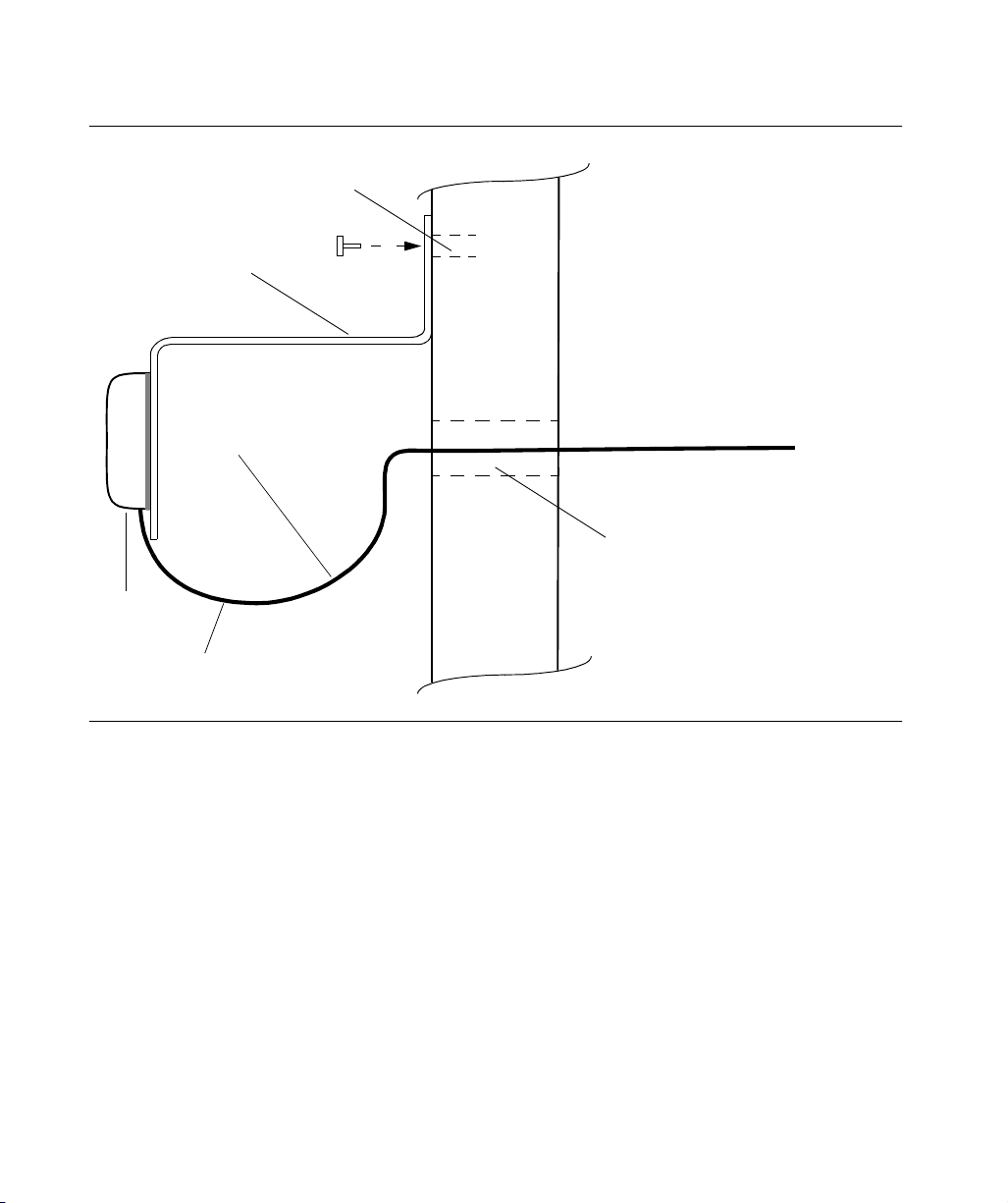
7 Push the SMA connector of the antenna cable through the hole drilled in the wall in
Step 3. Be sure the antenna cable forms a drip loop between the antenna and the
cable entry into the building (Figure 21).
8 Route the antenna cable to the antenna side of the IF converter and connect the
cable.
9 Connect a cable to the TimeSource 3600 shelf side of the IF downconverter and
route the cable to the shelf location.
10 Secure the cable using local company procedures.
11 Install fire-stopping material in all holes opened in the roof and/or walls during this
procedure.
12 Check all connections for tightness to prevent intermittent operation.
13 Coat all exposed connectors with an electrically conductive antioxidant compound
(e.g., Kopr-Shield spray).
3
3
Figure 20. Hole Spacing
8.6 cm
End of Procedure
5 cm
2.5 cm
Bracket mounting hole (2)
Antenna Cable hole
Installation
4
5
75
Page 76
SSSSSSSSSSSS SSSSSSSSSS SSSSSSS
Figure 21. Wall Antenna Mounting
Holes for
bolts/screws
Mounting
bracket
Antenna
cable
Antenna
Wall
Hole for cable
76
Drip loop
TimeSource 3600
Building exterior Building interior
Page 77

SSSSSSSSSSSS SSSSSSSSSS SSSSSSS
Rack Mounting
The shelf is shipped with the ears positioned for ETSI 53.5 cm
mounting (Figure 22A). For 48 cm racks, the shelf can be
positioned to the rear of the rack rail for flush mounting
(Figure 22B) or to the front of the rack rail for 12.7 cm offset
mounting (Figure 22C). Leave 1 RU (4.4 cm) of air space above the
TimeSource 3600 Shelf for proper ventilation. Mount the shelf in
the rack according to standard company practices.
Figure 22. Rack Mounting Options
Rack rails
Rear of rack
Top of shelf
Mounting ears
A. ETSI – 53.5 cm rack
3
3
Mounting ears
Rear of rack
Top of shelf
Top of shelf
Rack rails Mounting ears
B. Flush mounting – 48 cm rack
Rack rails
Rear of rack
Top of shelf
Top of shelf
C. 12.7 cm offset – 48 cm rack
Installation
4
12.7
cm
5
77
Page 78

SSSSSSSSSSSS SSSSSSSSSS SSSSSSS
Output Module Installation
Warning:
to electrostatic discharge (ESD) damage. Be sure to wear an
ESD wrist strap when making connections to the connector
panel. Failure to observe this warning may result in
equipment damage.
If an E1 8-output module, a IRIG-B 4-output module, or a ESCIU
2-port module is supplied with the system, install the module as
follows:
1. Remove the shelf cover to access the shelf connector panel.
2. Plug the module into the OPTIONS I/O connector on the
3. Align the three spring-loaded screws on the module with the
4. Use a medium flat-blade screwdriver to lock each screw in
The circuitry on the plug-in circuit board is subject
connector panel (refer to Figure 23).
threaded holes on the panel.
place. Torque the screws evenly to prevent skewing the
module.
78
TimeSource 3600
Page 79
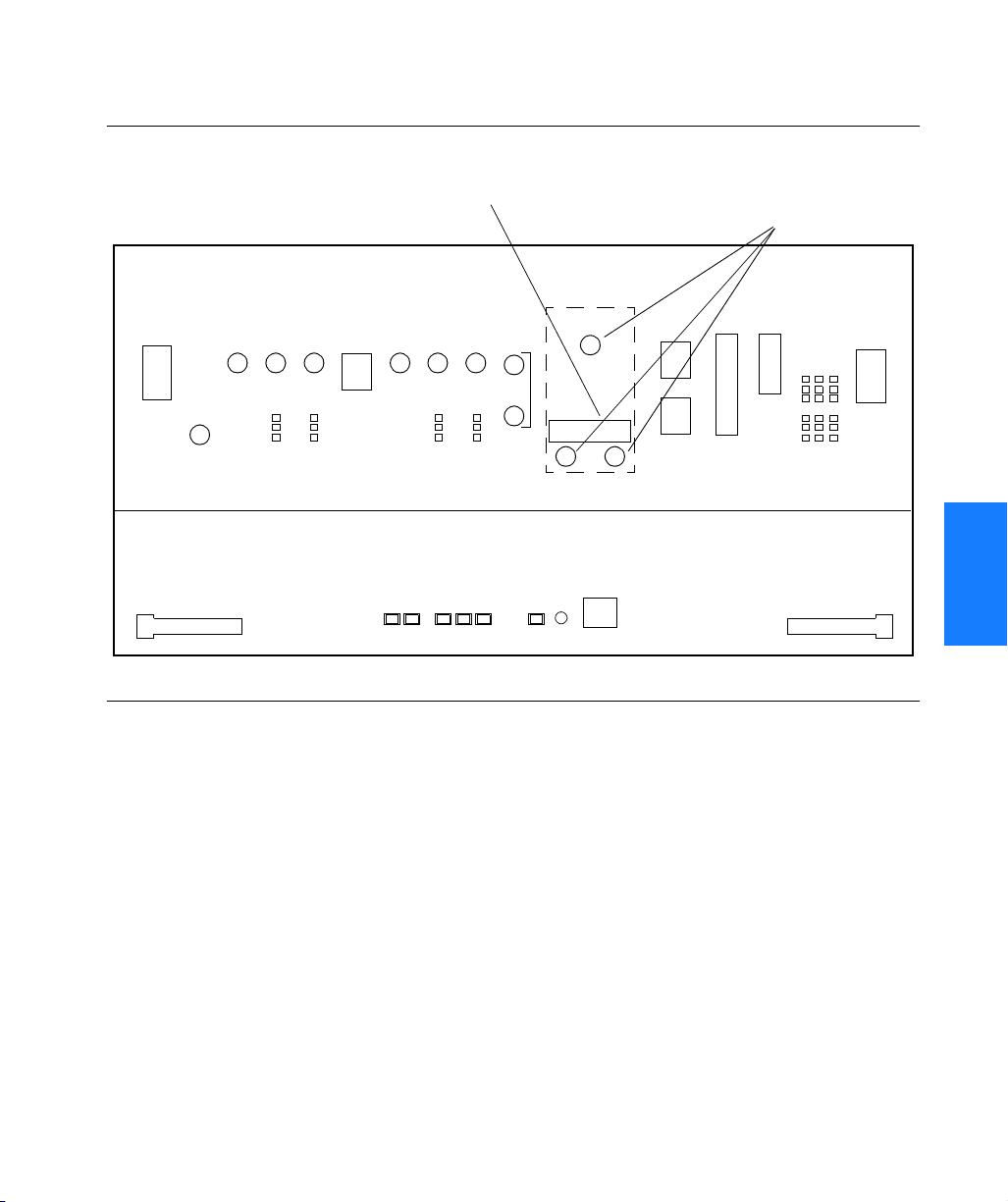
SSSSSSSSSSSS SSSSSSSSSS SSSSSSS
Figure 23. Options I/O Connector
OPTIONS I/O connector
Threaded screw holes
3
3
Installation
4
5
79
Page 80

SSSSSSSSSSSS SSSSSSSSSS SSSSSSS
Power and Signal Cabling
Warning:
to electrostatic discharge (ESD) damage. Be sure to wear an
ESD wrist strap when making connections to the connector
panel. Failure to observe this warning may result in
equipment damage.
Warning:
bonded to the metal plate with an adhesive. The overlay is an
integral part of the ESD protection. Do not pierce, peel, or
otherwise violate the integrity of the overlay. Failure to
observe this warning may result in equipment damage.
The Craft connection is made at the shelf front panel. All other
connections are made at the shelf connector panel. To access the
shelf connector panel, remove its cover.
Figure 24 shows the connectors on the front panel and connector
panel.
The circuitry on the plug-in circuit board is subject
The faceplate on the card contains a plastic overlay
80
TimeSource 3600
Page 81

SSSSSSSSSSSS SSSSSSSSSS SSSSSSS
Figure 24. Connector Panel and Front Panel Connectors
10 MHz
output
E1 outputs
A & B
(BNC)
Battery A
& frame
ground
(TB2)
1 pps
output
E1 inputs A & B
(BNC)
E1 outputs
A & B
(wire-wrap)
GPS
antenna
input
Time of day
E1 inputs
A & B
(wire-wrap)
Expansion Bus
(Reserved for
future use)
Com
port 1
4 IRIG-B TOD outputs (BNC) or
Alarms
Com
port 2
Craft
Output Module:
8 E1 outputs (BNC or
wire-wrap) or
2 ESCIU ports (BNC or
wire-wrap)
Battery B
& frame
ground
(TB1)
Ethernet
3
3
4
Installation
5
81
Page 82

SSSSSSSSSSSS SSSSSSSSSS SSSSSSS
Frame Ground
Frame ground connections are made on power terminal blocks
TB1 and TB2. Refer to Figure 24 for the location of the terminals
on the rear of the shelf, and refer to Figure 25 for the terminal
connections.
Figure 25. Connector Panel Terminal Block Connections
TB (1 or 2)
BATT (A or B)
RTN
N/C
82
Ensure the frame ground wires are long enough to reach from the
shelf connector panel to the frame ground connection. Use one
1.47 mm (16 AWG) green insulated wire to connect the frame
ground ( ) terminal of power terminal block TB1 to the frame
ground, and use another 1.47 mm (16 AWG) green insulated wire
to connect the terminal of TB2 to frame ground.
TimeSource 3600
Page 83

SSSSSSSSSSSS SSSSSSSSSS SSSSSSS
Make the ground connection, following one of the methods
described below, depending on whether a ground rod is installed:
With ground rod:
Solder the frame ground connection to the 4.115 mm (6 AWG)
frame ground rod run vertically on each side of the rack. Two
methods are acceptable:
• Crimp an appropriate-size spade lug (user-supplied) to the
1.47 mm (16 AWG) wire, bend the lug around the 4.115
mm (6 AWG) rod, and solder.
• Strip enough insulation from the 1.47 mm (16 AWG) wire
to permit three complete turns around the 4.115 mm
(6 AWG) rod, and solder.
Note:
the 4.115 mm (6 AWG) rod is heated sufficiently to prevent a
cold solder connection.
When soldering, use a 25 watt soldering iron to ensure
Without ground rod:
Crimp the supplied spade lug to the 1.47 mm (16 AWG) wire, and
screw the lug to a screw hole on the rack. Remove the paint and
use sandpaper or a file to remove oxidation around the screw hole
to ensure proper conductivity. Coat the connection with an
electrically conductive antioxidant compound, for example, KoprShield spray.
Crimp the supplied spade lug to the other end of the 1.47 mm
(16 AWG) wire, and connect it to the terminals on TB1 and TB2
(Figure 25).
If the power is not to be connected immediately, replace the
protective covers on the terminal blocks.
3
3
4
5
Installation
83
Page 84

SSSSSSSSSSSS SSSSSSSSSS SSSSSSS
Power
Warning:
restricted access location. Power source protective fusing
must be provided as part of the installation.
Caution:
instructed in this procedure. Before connecting the power cables to
the TimeSource 3600, ensure the fuses are removed from the fuse
panel that supplies power to the power cables.
Note:
replaceable fuses in the TimeSource 3600.
Power connections are made on power terminal blocks TB1 and
TB2. Refer to Figure 24 for the location of the terminals on the
rear of the shelf, and refer to Figure 25 for the terminal
connections.
Remove the protective covers from the terminal blocks, if covered.
Ensure the power wires are long enough to reach from the shelf
connector panel to the office battery source connection.
Use two 1.47mm (16 AWG) stranded wires for the power
connection, one with red insulation (BATT), and the other with
black insulation (RTN). Crimp a supplied spade lug to each wire.
This equipment is intended for installation in a
Do not apply power to the TimeSource 3600 before
Input power is reverse polarity protected; there are no user
84
Connect the power wires with red insulation to the –48V wire
receptacles on TB1 and TB2. Connect the power wires with black
insulation to the RTN wire receptacles on TB1 and TB2.
Replace the protective covers on the terminal blocks.
Note:
recommended. If separate office battery supplies are not available,
connect a single office battery to both inputs (TB1 and TB2) to
avoid a standing battery-failure alarm.
TimeSource 3600
Two separate office battery supplies (–48V A and –48V B) are
Page 85

SSSSSSSSSSSS SSSSSSSSSS SSSSSSS
GPS Antenna
Use the supplied 90 degree adapter to connect the coaxial cable
from the lightning suppressor or IF downconverter to the TNC
connector labeled GPS ANT. Refer to Figure 24 for the connector
location.
10 MHz Output
Connect a user-supplied RG-58 coaxial cable from the connector
labeled 10 MHz to the equipment that will use the 10 MHz output
signal. See Figure 24 for the connector location.
3
3
Installation
4
5
85
Page 86

SSSSSSSSSSSS SSSSSSSSSS SSSSSSS
E1 or Analog Synchronization Outputs
Warning:
lightning protection, do not connect the E1 output line
directly to a point outside the building. Failure to observe this
warning may result in equipment damage.
Connect the E1 or analog synchronization outputs at the wirewrap pins or BNC connectors labeled E1 OUT A and E1 OUT B. If
using the wire-wrap pins, connect the tip wire to the pins labeled
T, the ring wire to the pins labeled R, and the shield to the pins
labeled S. See Figure 24 for the location of the connectors and
pins, and Figure 26 for the wire-wrap connections.
Because the E1 output circuits do not provide
Notes:
1. For wire-wrap connections, the shield pin is provided to ground
the cable shield at the shelf, if required. Normally, the shield is
grounded at the source. Grounding the shield at both ends is not
recommended.
2. A BNC connector can be used for one output, and a wire-wrap
connector can be used for the other output, but do not use the
BNC and wire-wrap connectors of the same output
simultaneously. For example, a BNC connector can be used for
output A and the wire-wrap pins for output B, but do not use
the output A BNC connector with the output A wire-wrap
connector.
Figure 26. E1 or Analog Output Wire-Wrap Connections
86
B
T
R
S
TimeSource 3600
A
T
R
S
Page 87

SSSSSSSSSSSS SSSSSSSSSS SSSSSSS
Expansion Bus
Reserved for future use.
1 PPS Output
Connect a user-supplied RG-58 coaxial cable from the connector
labeled TTL PPS to the equipment that will use the 1 pulse-persecond TTL output signal. See Figure 24 for the connector
location.
3
3
Installation
4
5
87
Page 88

SSSSSSSSSSSS SSSSSSSSSS SSSSSSS
E1 or Analog Reference Inputs
Warning:
lightning protection, do not connect the E1 input line directly
to a point outside the building. Failure to observe this
warning may result in equipment damage.
E1 or analog reference sources, traceable to an independent
Stratum 1 source, can be connected to further increase holdover
stability, or to be monitored by the TimeSource 3600. In either
case, connect reference inputs to the wire-wrap pins or BNC
connectors labeled SPAN IN A and SPAN IN B. If using the wirewrap pins, connect the tip wire to the pin labeled T, the ring wire
to the pin labeled R, and the shield (if connected at the
TimeSource 3600) to the pin labeled S. See Figure 24 for the
location of the connectors and pins, and Figure 27 for the wirewrap connections.
Because the E1 input circuits do not provide
Notes:
1. The shield pin is capacitively coupled to ground. Normally, the
shield is grounded at the source. Grounding the shield at both
ends is not
2. A BNC connector can be used for one input, and a wire-wrap
connector can be used for the other input, but do not use the
BNC and wire-wrap connectors of the same input
simultaneously. For example, a BNC connector can be used for
input A and the wire-wrap pins for input B, but do not use the
input A BNC connector with the input A wire-wrap connector.
recommended.
Figure 27. E1 or Analog Input Wire-Wrap Connections
B
T
R
S
88
TimeSource 3600
A
T
R
S
Page 89

SSSSSSSSSSSS SSSSSSSSSS SSSSSSS
Module for Additional E1 or Analog Outputs (990-72060-02 System Only)
Connect up to eight optional E1 or analog outputs at the wirewrap or BNC output module. See Figure 24 for the connector
location, and Figure 28 for the connections.
Note:
The shield pin is capacitively coupled to ground, therefore,
the shield must be connected at the source end. The shield may
also be connected at the TimeSource 3600 end for additional
longitudinal noise protection.
Figure 28. Eight E1 or Analog Outputs Connections
Wire-Wrap BNC
OUT 7OUT 8
Output 8
Output 5
Output 6
Output 3
T
R
S
OUT 6 OUT 5 OUT 4
T
R
S
T
R
S
T
R
S
T
R
S
T
Output 7
R
S
T
Output 4
R
S
Output 2
OUT 1OUT 2OUT 3
T
Output 1
R
S
Output 8
Output 6
Output 4
Output 2
OUT 8
OUT 6
OUT 4
OUT 2
OUT 7
OUT 5
OUT 3
OUT 1
Output 7
Output 5
Output 3
Output 1
3
3
4
Installation
5
89
Page 90

SSSSSSSSSSSS SSSSSSSSSS SSSSSSS
Module for IRIG-B TOD Outputs (990-72060-05 System Only)
Connect up to four optional IRIG-B TOD outputs at the output
module. See Figure 24 for the connector location, and Figure 29
for the connections.
Figure 29. IRIG-B TOD Output Connections
Note:
Output 4
Output 2
OUT 8
OUT 6
OUT 4
OUT 2 OUT 1
OUT 7
OUT 5
OUT 3
Note: Outputs 5, 6, 7 and 8 are not used
Output 3
Output 1
90
TimeSource 3600
Page 91

SSSSSSSSSSSS SSSSSSSSSS SSSSSSS
Module for ESCIU Ports (990-72060-04 System Only)
The ESCIU ports (Figure 30) have a different function than the
synchronization outputs. A synchronization output provides an
all-ones reference clock signals for network elements. An ESCIU
port carries live E1 traffic, and synchronizes the live traffic as it
passes through. The ESCIU module can synchronize 2 spans in
one direction. The return direction passes through as it is.
The ESCIU ports can connect at the digital distribution frame
(DDF). The network elements receiving the ESCIU output signal
must be able to receive E1 signals that conform to CCITT G.703
paragraph 6 specifications. The network element can be
configured to extract its timing from the live E1 traffic signal.
A bypass relay directs E1 traffic around the ESCIU circuitry to
maintain span continuity if a TimeSource 3600 fault occurs.
Figure 30. Connector Layout of ESCIU Modules
Span 2 NE
return (not syn-
chronized)
Span 2 to NE
(synchronized)
RTN2 OUT
RTN2 IN
OUT
IN
SPAN 2
RTN1 OUT
RTN1 IN
OUT
IN
SPAN 1
Span 1 NE
return (not
synchronized)
Span 1 to NE
(synchronized)
Span 2 NE
return (not
synchronized)
Span 2 toNE
(synchronized)
RTN2
SPAN 2 SPAN 1
IN
OUT
T
R
S
IN
T
R
S
OUT
T
R
S
IN
RTN1
T
R
S
T
R
S
T
R
S
OUT
IN
OUT
Span 1 NE
return (not
synchronized)
Span 1 to NE
(synchronized)
3
3
4
BNC Module Wire-Wrap Module
Installation
5
91
Page 92

SSSSSSSSSSSS SSSSSSSSSS SSSSSSS
Cutover Procedures for Out-of-Service Equipment
If DDF access jack sets are not cabled to the ESCIU module, the
following out-of-service cutover procedure must be used. Consult
the local company Installation Job Specifications to ensure that
the network element to be retimed is connected to the ESCIU
module correctly. Refer to Figure 31 for the following procedure:
1. Remove from service (turn down) the traffic trunks on the E1
system to be cutover to the ESCIU module.
2. Remove the existing cabling in both directions between the
transmit (OUT) and receive (IN) terminals of the NEs that will
connect to the ESCIU module.
3. In the direction not to be synchronized by the ESCIU module,
connect new cables from the ESCIU module RTNx IN connector
to the NE transmit (OUT) terminal, and connect from the ESCIU
module RTNx OUT connector to the NE receive (IN) terminal.
4. In the direction to be synchronized by the ESCIU module,
connect new cables from the ESCIU module IN connector to the
NE transmit (OUT) terminal, and connect from the ESCIU
module OUT connector to the NE receive (IN) terminal.
92
5. Verify that there are no alarms on the NEs on the E1 system. If
Note:
satellites, alarms may be present. All synchronization-related alarms
should clear while the TimeSource 3600 is in steady-state operation.
6. Restore (turn up) the traffic trunks to service.
TimeSource 3600
there are alarms, recheck the new cabling between the NEs and
the ESCIU module.
If the TimeSource 3600 is still in warm-up or searching for GPS
Page 93

SSSSSSSSSSSS SSSSSSSSSS SSSSSSS
Figure 31. ESCIU Cutover without Jacks (Out-of-Service)
REMOVE EXISTING
NETWORK
ELEMENT OR
FACILITY
NOT BEING
TIMED FROM
ESCIU
MODULE
RECEIVE
(IN)
TRANSMIT
(OUT)
CABLING
RTN1 OUT
RTN1 IN
RECEIVE
(IN)
TRANSMIT
(OUT)
NETWORK
ELEMENT
BEING TIMED
FROM
ESCIU
MODULE
SPAN 1
ESCIU
MODULE
OUT
IN
Existing cabling
Remove existing cabling
New cabling
Connection point
Installation
93
3
3
4
5
Page 94

SSSSSSSSSSSS SSSSSSSSSS SSSSSSS
Cutover Procedures for In-Service Equipment
If standard digital signal level access jack sets, such as DDF or DSX-1
jacks, were cabled to the ESCIU module, the following in-service
cutover procedure must be used. Consult the local company
Installation Job Specifications to ensure that the network element to
be retimed from the ESCIU module is connected to the ESCIU module
A OUT terminals. Refer to Figure 32 for the following procedure:
1. Patch a bridging repeater from the MON jack of one NE to the IN
jack of the other NE in both directions of transmission on the E1
system to be cutover. Place a 75 Ω termination plug in the OUT
jack in each direction.
2. Remove the cross-connect wiring from the OUT and IN jacks (offnormal side of jacks) in both directions of transmission.
3. In the direction not to be synchronized by the ESCIU module,
connect new cables from the ESCIU module RTNx IN connector
to the NE transmit (OUT) terminal, and connect from the ESCIU
module RTNx OUT connector to the NE receive (IN) terminal.
4. In the direction to be synchronized by the ESCIU module,
connect new cables from the ESCIU module IN connector to the
NE transmit (OUT) terminal, and connect from the ESCIU
module OUT connector to the NE receive (IN) terminal.
94
5. Remove the 75 Ω (E1) termination plug from the OUT jack and
6. Verify that there are no alarms on the NEs on the E1 system. If
Note:
satellites, alarms may be present. All synchronization-related alarms
should clear while the TimeSource 3600 is in steady-state operation.
7. Remove the remaining patch cords from the NE MON jack.
TimeSource 3600
patch cords from the NE IN jack. The E1 system bitstream is now
going through the ESCIU module.
there are alarms, repeat Step 1 and recheck the cross-connect
wiring. Repeat Step 5.
If the TimeSource 3600 is still in warm-up or searching for GPS
Page 95

SSSSSSSSSSSS SSSSSSSSSS SSSSSSS
Figure 32. ESCIU Cutover with Jacks (In-Service)
PRIMARY
REFERENCE
E1
LINE
INTF
EQPMT
SECONDARY
REFERENCE
E1
LINE
INTF
EQPMT
T
R
T
R
T
R
T
R
IN
OUT
MON
IN
OUT
1
2
2
1
1
2
2
OUT
IN
OUT
IN
MON
MON
T
R
INTERFACE
T
R
T
R
INTERFACE
T
R
E1
DIGITAL
PORT
DIGITAL
SWITCH
MACHINE*
E1
DIGITAL
PORT
3
3
1
Patch Cord
Bridging Repeaters
DSX-1 Jacks
Existing cabling
2
to be removed
3
ESCIU cabling
Refer to In-Service
Equipment for procedures
MON
3
OUT
3
IN
MON
1
RTN1 OUT
RTN1 IN
OUT
IN
SPAN 1
3
IN
OUT
MON
ESCIU
MODULE
3
4
* Some digital switch
machines designate
two traffic-carrying
E1 systems as their
primary and
secondary clock
reference sources.
Installation
95
5
Page 96

SSSSSSSSSSSS SSSSSSSSSS SSSSSSS
Time of Day Output
Connect a time of day (TOD) output at the female RJ-45 connector
labeled TOD. See Figure 24 for the connector location, and Table B
for the connector pinouts.
Table B. TOD Connector Pinouts
Pin Signal Abbreviation Direction
1 1 pps A TOD PPS + From TimeSource 3600
2 1 pps B TOD PPS – From TimeSource 3600
3 12 V power source TOD P12V —
4 Receive data B TOD RXD – To TimeSource 3600
5 Receive data A TOD RXD + To TimeSource 3600
6 Circuit ground TOD GND —
7 Transmit data A TOD TXD + From TimeSource 3600
96
8 Transmit data B TOD TXD – From TimeSource 3600
Note: Pins not listed are reserved for future use.
If the device receiving the time code (for example, Cisco router)
accepts an RS-232 cable instead of an RS-422 cable, follow
Procedure F to install the RS-422–to–RS-232 TOD converter.
Note:
Cisco router or NTP Type 4 compatible device is installed, and
power applied, per manufacturer’s instructions.
TimeSource 3600
Before performing Procedure F, ensure that the appropriate
Page 97

SSSSSSSSSSSS SSSSSSSSSS SSSSSSS
Procedure F. RJ-422–to–RS-232 TOD Converter Installation
Step Procedure
1 Secure the provided mounting plate to the RS-422–to–RS-232 TOD converter, using
the two provided screws. The plate may be attached to the top or front of the
converter, depending on the desired surface (for example, a rack or cabinet) to which
the converter will be mounted (see Figure 33).
Notes:
1. Due to distance constraints, the converter must be placed no more than 305 m
from the TimeSource 3600 Shelf, and no more than 15 m from the device
receiving the time code.
2. The converter dimensions are 7.5 cm by 3.8 cm by 2.5 cm.
3. The mounting plate dimensions are 7.5 cm by 5 cm.
2 Secure the converter to the desired surface, using the slots in the plate and user-
supplied bolts.
3 Install a user-supplied Category 5 four-pair RS-422 cable, with RJ-45 connectors on
each end, between the TimeSource 3600 Shelf and the converter (see Figure 34).
4 Install a user-supplied RS-232 cable, with DB-25 connectors on each end, between
the converter and the device receiving the time code (see Figure 34). See Table
Table C for the DB-25 connector pinouts.
End of Procedure
Figure 33. RS-422–to–RS-232 TOD Converter Mounting Plate
Screws
(supplied)
TOD
Converter
Mounting plate
attached to top
of converter
TOD
Converter
Mounting plate
attached to front
of converter
Screws
(supplied)
Installation
97
3
3
4
5
Page 98
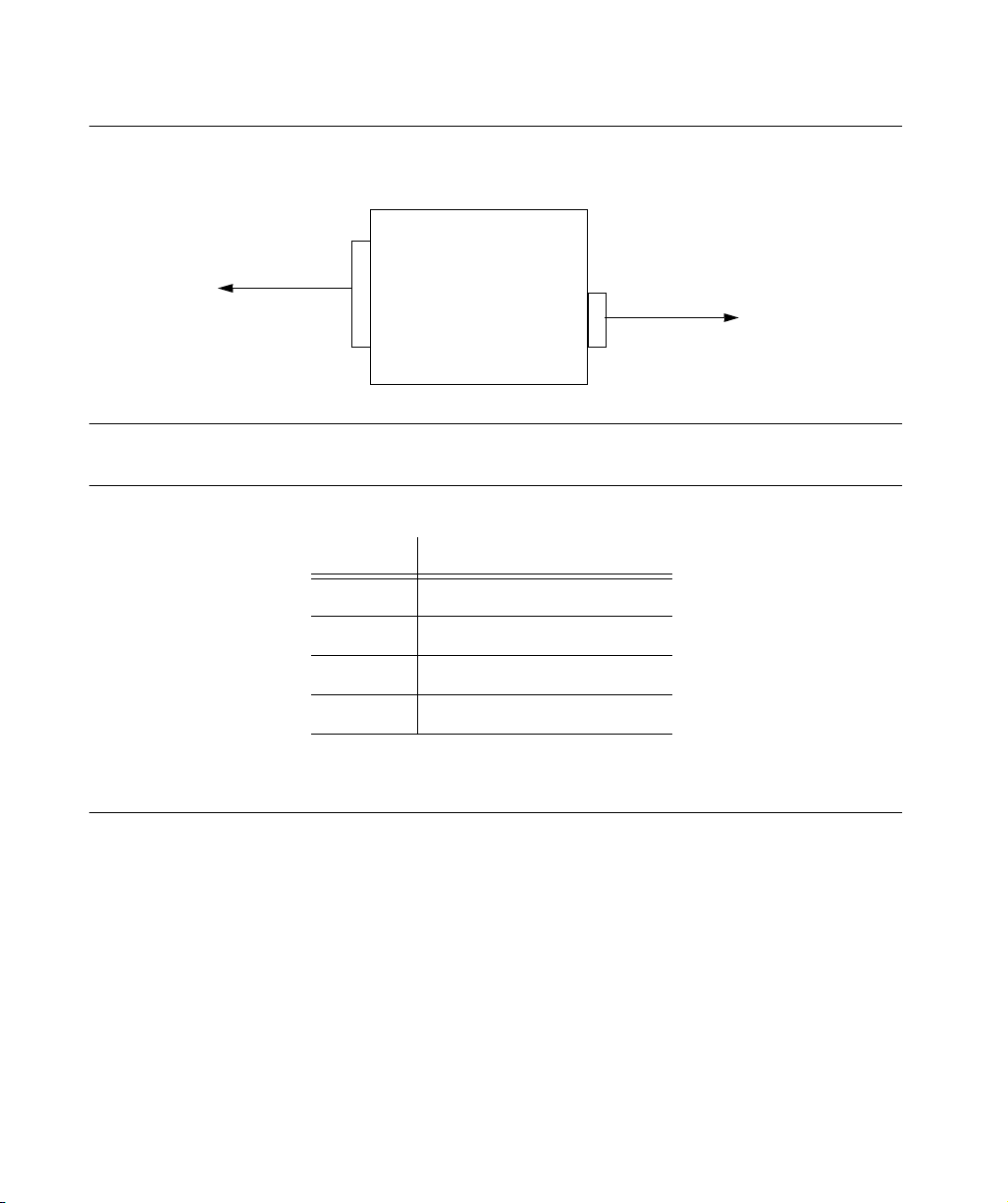
SSSSSSSSSSSS SSSSSSSSSS SSSSSSS
Figure 34. RS-422–to–RS-232 TOD Converter Connections
DB-25
Connector
To device
receiving
time code
(Female)
15 m
max.
TOD
Converter
RJ-45
Connector
(Female)
Table C. Converter DB-25 Connector Pinouts
Pin Signal
1 Frame ground
3 Data output (RS-232)
305 m
max.
To TimeSource
3600
98
5 1 pps (RS-232)
7 Signal ground
Note: Pins not listed are reserved for
future use.
TimeSource 3600
Page 99

SSSSSSSSSSSS SSSSSSSSSS SSSSSSS
Ethernet
Connect a user-supplied Ethernet cable from the network to the
10base-T Ethernet connector labeled E-NET. See Figure 24 for the
connector location, and Table D for the connector pinouts.
Table D. Ethernet 10base-T RJ-45 Connector Pinouts
Pin Signal Abbreviation Direction
1 Transmit data + TXD + From TimeSource 3600
2 Transmit data – TXD – From TimeSource 3600
3 Receive data + RXD + To TimeSource 3600
4— — —
5— — —
6 Receive data – RXD – To TimeSource 3600
7— — —
3
3
8— — —
Installation
99
4
5
Page 100

SSSSSSSSSSSS SSSSSSSSSS SSSSSSS
Communication Port 1
To provide an RS-232 link for TL1 command access to the
TimeSource 3600, connect to port 1 at the female 25-pin D
connector labeled COM1. See Figure 24 for the location of the
connector. See Table E for the connector pinouts.
Note:
data on pin 3. Be sure the other equipment receives data from the
transmitting pin, and transmits data to the receiving pin.
Table E. COM1 Connector Pinouts
Pin Signal Abbreviation Direction
2 Transmit data TXD From TimeSource 3600
3 Receive data RXD To TimeSource 3600
4 Request to send RTS From TimeSource 3600
5 Clear to send CTS To TimeSource 3600
7Signal ground GND —
20 Data terminal ready DTR From TimeSource 3600
The COM1 connector transmits data on pin 2, and receives
Note: Pins not listed are reserved for future use.
100
TimeSource 3600
 Loading...