

Page 1

TimeSource 3100
GPS Primary Reference Source
User Guide
Revision K – December 2005
Part Number 097-72020-01
Page 2

Symmetricom, Inc.
2300 Orchard Parkway
San Jose, CA 95131-1017
U.S.A.
http://www.symmetricom.com
Copyright © 2003–2005 Symmetricom, Inc.
All rights reserved. Printed in U.S.A.
All product names, service marks, trademarks, and registered trademarks
used in this document are the property of their respective owners.
Page 3

Table of Contents
Contents
How to Use This Guide
Chapter 1 Overview of the TimeSource 3100
Overview . . . . . . . . . . . . . . . . . . . . . . . . . . . . . . . . . . . . . . . . . . . . . . . . . . . . . . . . . . 18
Global Positioning System . . . . . . . . . . . . . . . . . . . . . . . . . . . . . . . . . . . . . . . . 18
Physical Description. . . . . . . . . . . . . . . . . . . . . . . . . . . . . . . . . . . . . . . . . . . . . . . . . . 18
Roof Antenna. . . . . . . . . . . . . . . . . . . . . . . . . . . . . . . . . . . . . . . . . . . . . . . . . . . . . . . 20
Functional Description . . . . . . . . . . . . . . . . . . . . . . . . . . . . . . . . . . . . . . . . . . . . . . . . 20
Overview . . . . . . . . . . . . . . . . . . . . . . . . . . . . . . . . . . . . . . . . . . . . . . . . . . . . . . 20
Antenna. . . . . . . . . . . . . . . . . . . . . . . . . . . . . . . . . . . . . . . . . . . . . . . . . . . . . . . 22
IF Interface . . . . . . . . . . . . . . . . . . . . . . . . . . . . . . . . . . . . . . . . . . . . . . . . . . . . 22
Local Oscillator . . . . . . . . . . . . . . . . . . . . . . . . . . . . . . . . . . . . . . . . . . . . . . . . . 22
Clock Extractors . . . . . . . . . . . . . . . . . . . . . . . . . . . . . . . . . . . . . . . . . . . . . . . . 22
Power Supply . . . . . . . . . . . . . . . . . . . . . . . . . . . . . . . . . . . . . . . . . . . . . . . . . . 22
NTP TimeServer . . . . . . . . . . . . . . . . . . . . . . . . . . . . . . . . . . . . . . . . . . . . . . . . 22
Network Time Protocol Password Activation. . . . . . . . . . . . . . . . . . . . . . . . . . . 23
BesTime Ensemble Timing Generator . . . . . . . . . . . . . . . . . . . . . . . . . . . . . . . 23
E1 or Analog Outputs . . . . . . . . . . . . . . . . . . . . . . . . . . . . . . . . . . . . . . . . . . . . 23
Eight Mixed E1/T1 Outputs (990-72020-06 Systems Only) . . . . . . . . . . . . . . . 23
Eight Additional E1 Outputs (990-72020-02 Systems Only) . . . . . . . . . . . . . . . 24
TOD Output. . . . . . . . . . . . . . . . . . . . . . . . . . . . . . . . . . . . . . . . . . . . . . . . . . . . 24
IRIG-B TOD Outputs (990-72020-05 Systems Only) . . . . . . . . . . . . . . . . . . . . 24
1 PPS Output . . . . . . . . . . . . . . . . . . . . . . . . . . . . . . . . . . . . . . . . . . . . . . . . . . 24
10 MHz Output . . . . . . . . . . . . . . . . . . . . . . . . . . . . . . . . . . . . . . . . . . . . . . . . . 24
Two ESCIU Ports (990-72020-04 Systems Only). . . . . . . . . . . . . . . . . . . . . . . 24
Alarm Interface . . . . . . . . . . . . . . . . . . . . . . . . . . . . . . . . . . . . . . . . . . . . . . . . . 25
Communications Ports . . . . . . . . . . . . . . . . . . . . . . . . . . . . . . . . . . . . . . . . . . . 25
Ethernet. . . . . . . . . . . . . . . . . . . . . . . . . . . . . . . . . . . . . . . . . . . . . . . . . . . . . . . 25
Passthrough . . . . . . . . . . . . . . . . . . . . . . . . . . . . . . . . . . . . . . . . . . . . . . . . . . . 25
Alarm Programmability . . . . . . . . . . . . . . . . . . . . . . . . . . . . . . . . . . . . . . . . . . . 26
Startup. . . . . . . . . . . . . . . . . . . . . . . . . . . . . . . . . . . . . . . . . . . . . . . . . . . . . . . . 27
Bridging/Holdover Behavior. . . . . . . . . . . . . . . . . . . . . . . . . . . . . . . . . . . . . . . . 28
Time Figure of Merit . . . . . . . . . . . . . . . . . . . . . . . . . . . . . . . . . . . . . . . . . . . . . 29
Chapter 2 Engineering & Ordering
Site Survey. . . . . . . . . . . . . . . . . . . . . . . . . . . . . . . . . . . . . . . . . . . . . . . . . . . . . . . . . 32
Lightning Suppressor Guidelines. . . . . . . . . . . . . . . . . . . . . . . . . . . . . . . . . . . . . . . . 33
Antenna Location Guidelines. . . . . . . . . . . . . . . . . . . . . . . . . . . . . . . . . . . . . . . . . . . 33
Earth Ground Location Guidelines. . . . . . . . . . . . . . . . . . . . . . . . . . . . . . . . . . . . . . . 36
Antenna Cable Choices . . . . . . . . . . . . . . . . . . . . . . . . . . . . . . . . . . . . . . . . . . . . . . . 37
Remote Oscillator Cabling. . . . . . . . . . . . . . . . . . . . . . . . . . . . . . . . . . . . . . . . . 38
097-72020-01 Revision K – December 2005 TimeSource 3100 User’s Guide iii
Page 4

Table of Contents
IRIG-B TOD (990-72020-05 Systems Only) . . . . . . . . . . . . . . . . . . . . . . . . . . . 39
RJ-422–to–RJ-232 TOD Converter. . . . . . . . . . . . . . . . . . . . . . . . . . . . . . . . . . 39
Shelf Considerations . . . . . . . . . . . . . . . . . . . . . . . . . . . . . . . . . . . . . . . . . . . . . . . . . 39
Systems . . . . . . . . . . . . . . . . . . . . . . . . . . . . . . . . . . . . . . . . . . . . . . . . . . . . . . . . . . . 40
Standard System (Two E1 or 2.048 MHz Outputs). . . . . . . . . . . . . . . . . . . . . . 40
With Eight Additional E1 or 2.048 MHz Outputs . . . . . . . . . . . . . . . . . . . . . . . . 41
With Eight Additional Mixed E1/T1Outputs. . . . . . . . . . . . . . . . . . . . . . . . . . . . 41
With Two E1 Synchronization Insertion (ESCIU) Ports. . . . . . . . . . . . . . . . . . . 42
With Four IRIG-B TOD Outputs. . . . . . . . . . . . . . . . . . . . . . . . . . . . . . . . . . . . . 42
User-Supplied Tools and Materials . . . . . . . . . . . . . . . . . . . . . . . . . . . . . . . . . . . . . . 43
For Antenna Installation . . . . . . . . . . . . . . . . . . . . . . . . . . . . . . . . . . . . . . . . . . 43
For Shelf Installation . . . . . . . . . . . . . . . . . . . . . . . . . . . . . . . . . . . . . . . . . . . . . 43
Outputs, Power, and Miscellaneous . . . . . . . . . . . . . . . . . . . . . . . . . . . . . . . . . 43
Chapter 3 Installing the TimeSource 3100
Unpacking the Unit . . . . . . . . . . . . . . . . . . . . . . . . . . . . . . . . . . . . . . . . . . . . . . . . . . . 46
Installing the Antenna. . . . . . . . . . . . . . . . . . . . . . . . . . . . . . . . . . . . . . . . . . . . . . . . . 47
Installing the Shelf . . . . . . . . . . . . . . . . . . . . . . . . . . . . . . . . . . . . . . . . . . . . . . . . . . . 51
Installing Output Modules . . . . . . . . . . . . . . . . . . . . . . . . . . . . . . . . . . . . . . . . . 51
Rack Mounting . . . . . . . . . . . . . . . . . . . . . . . . . . . . . . . . . . . . . . . . . . . . . . . . . 52
Making Cable Connections . . . . . . . . . . . . . . . . . . . . . . . . . . . . . . . . . . . . . . . . . . . . 53
Frame Ground. . . . . . . . . . . . . . . . . . . . . . . . . . . . . . . . . . . . . . . . . . . . . . . . . . 54
Making Power Connections. . . . . . . . . . . . . . . . . . . . . . . . . . . . . . . . . . . . . . . . 56
Making GPS Antenna Connections. . . . . . . . . . . . . . . . . . . . . . . . . . . . . . . . . . 56
Making 10 MHz Output Connections. . . . . . . . . . . . . . . . . . . . . . . . . . . . . . . . . 56
Making E1 or Analog Synchronization Output Connections . . . . . . . . . . . . . . . 57
Making 1 PPS Output Connections. . . . . . . . . . . . . . . . . . . . . . . . . . . . . . . . . . 57
Connecting E1 or Analog Reference Inputs . . . . . . . . . . . . . . . . . . . . . . . . . . . 58
Connecting Remote Oscillator Inputs . . . . . . . . . . . . . . . . . . . . . . . . . . . . . . . . 58
Installing a Module for Additional E1 or Analog Outputs. . . . . . . . . . . . . . . . . . 61
Installing the Mixed E1/T1 Output Module . . . . . . . . . . . . . . . . . . . . . . . . . . . . 62
Installing the IRIG-B TOD Output Module. . . . . . . . . . . . . . . . . . . . . . . . . . . . . 62
Installing the ESCIU Port Module . . . . . . . . . . . . . . . . . . . . . . . . . . . . . . . . . . . 63
Connecting the Time of Day Output . . . . . . . . . . . . . . . . . . . . . . . . . . . . . . . . . 68
Making Ethernet Connections. . . . . . . . . . . . . . . . . . . . . . . . . . . . . . . . . . . . . . 70
Connecting to Communication Port 1 . . . . . . . . . . . . . . . . . . . . . . . . . . . . . . . . 70
Connecting to Communication Port 2 . . . . . . . . . . . . . . . . . . . . . . . . . . . . . . . . 71
Connecting Alarm Outputs . . . . . . . . . . . . . . . . . . . . . . . . . . . . . . . . . . . . . . . . 71
Making Craft Port Connections . . . . . . . . . . . . . . . . . . . . . . . . . . . . . . . . . . . . . 72
Powering Up the Shelf . . . . . . . . . . . . . . . . . . . . . . . . . . . . . . . . . . . . . . . . . . . . . . . . 73
Installing TimeWizard. . . . . . . . . . . . . . . . . . . . . . . . . . . . . . . . . . . . . . . . . . . . . . . . . 81
Factory Default Values. . . . . . . . . . . . . . . . . . . . . . . . . . . . . . . . . . . . . . . . . . . . . . . . 90
iv TimeSource 3100 User’s Guide 097-72020-01 Revision K – December 2005
Page 5

Table of Contents
Chapter 4 TL1 Reference
Conventions. . . . . . . . . . . . . . . . . . . . . . . . . . . . . . . . . . . . . . . . . . . . . . . . . . . . . . . . 94
Command Format . . . . . . . . . . . . . . . . . . . . . . . . . . . . . . . . . . . . . . . . . . . . . . . . . . . 94
Response Format. . . . . . . . . . . . . . . . . . . . . . . . . . . . . . . . . . . . . . . . . . . . . . . . . . . . 95
Parameters. . . . . . . . . . . . . . . . . . . . . . . . . . . . . . . . . . . . . . . . . . . . . . . . . . . . . . . . . 96
Autonomous Messages . . . . . . . . . . . . . . . . . . . . . . . . . . . . . . . . . . . . . . . . . . . . . . . 99
Report Alarm. . . . . . . . . . . . . . . . . . . . . . . . . . . . . . . . . . . . . . . . . . . . . . . . . . . 99
Report Event . . . . . . . . . . . . . . . . . . . . . . . . . . . . . . . . . . . . . . . . . . . . . . . . . . . 99
Tasks/Commands . . . . . . . . . . . . . . . . . . . . . . . . . . . . . . . . . . . . . . . . . . . . . . . . . . 100
Commands. . . . . . . . . . . . . . . . . . . . . . . . . . . . . . . . . . . . . . . . . . . . . . . . . . . . . . . . 101
Activate User. . . . . . . . . . . . . . . . . . . . . . . . . . . . . . . . . . . . . . . . . . . . . . . . . . 102
Cancel User. . . . . . . . . . . . . . . . . . . . . . . . . . . . . . . . . . . . . . . . . . . . . . . . . . . 103
Copy Memory . . . . . . . . . . . . . . . . . . . . . . . . . . . . . . . . . . . . . . . . . . . . . . . . . 104
Delete Equipment . . . . . . . . . . . . . . . . . . . . . . . . . . . . . . . . . . . . . . . . . . . . . . 106
Delete User Security. . . . . . . . . . . . . . . . . . . . . . . . . . . . . . . . . . . . . . . . . . . . 107
Edit Communication . . . . . . . . . . . . . . . . . . . . . . . . . . . . . . . . . . . . . . . . . . . . 108
Edit Date . . . . . . . . . . . . . . . . . . . . . . . . . . . . . . . . . . . . . . . . . . . . . . . . . . . . . 111
Edit Equipment . . . . . . . . . . . . . . . . . . . . . . . . . . . . . . . . . . . . . . . . . . . . . . . . 113
Enter Equipment . . . . . . . . . . . . . . . . . . . . . . . . . . . . . . . . . . . . . . . . . . . . . . . 122
Enter User Security. . . . . . . . . . . . . . . . . . . . . . . . . . . . . . . . . . . . . . . . . . . . . 124
Initialize Log . . . . . . . . . . . . . . . . . . . . . . . . . . . . . . . . . . . . . . . . . . . . . . . . . . 125
Initialize Register. . . . . . . . . . . . . . . . . . . . . . . . . . . . . . . . . . . . . . . . . . . . . . . 126
Initialize System . . . . . . . . . . . . . . . . . . . . . . . . . . . . . . . . . . . . . . . . . . . . . . . 127
Operate Alarm Cutoff All . . . . . . . . . . . . . . . . . . . . . . . . . . . . . . . . . . . . . . . . . 128
Retrieve Alarm All . . . . . . . . . . . . . . . . . . . . . . . . . . . . . . . . . . . . . . . . . . . . . . 129
Retrieve Alarm Equipment . . . . . . . . . . . . . . . . . . . . . . . . . . . . . . . . . . . . . . . 130
Retrieve Communication. . . . . . . . . . . . . . . . . . . . . . . . . . . . . . . . . . . . . . . . . 131
Retrieve Condition All . . . . . . . . . . . . . . . . . . . . . . . . . . . . . . . . . . . . . . . . . . . 134
Retrieve Condition Equipment. . . . . . . . . . . . . . . . . . . . . . . . . . . . . . . . . . . . . 135
Retrieve Equipment. . . . . . . . . . . . . . . . . . . . . . . . . . . . . . . . . . . . . . . . . . . . . 136
Retrieve GPS Status. . . . . . . . . . . . . . . . . . . . . . . . . . . . . . . . . . . . . . . . . . . . 143
Retrieve Header . . . . . . . . . . . . . . . . . . . . . . . . . . . . . . . . . . . . . . . . . . . . . . . 144
Retrieve Inventory. . . . . . . . . . . . . . . . . . . . . . . . . . . . . . . . . . . . . . . . . . . . . . 145
Retrieve Log . . . . . . . . . . . . . . . . . . . . . . . . . . . . . . . . . . . . . . . . . . . . . . . . . . 147
Retrieve Performance Monitoring . . . . . . . . . . . . . . . . . . . . . . . . . . . . . . . . . . 148
Retrieve User Security . . . . . . . . . . . . . . . . . . . . . . . . . . . . . . . . . . . . . . . . . . 157
Set Source Identifier . . . . . . . . . . . . . . . . . . . . . . . . . . . . . . . . . . . . . . . . . . . . 158
Chapter 5 Troubleshooting
Troubleshooting with Front Panel Items. . . . . . . . . . . . . . . . . . . . . . . . . . . . . . . . . . 160
Troubleshooting with Error Messages . . . . . . . . . . . . . . . . . . . . . . . . . . . . . . . . . . . 164
Replacing Cards. . . . . . . . . . . . . . . . . . . . . . . . . . . . . . . . . . . . . . . . . . . . . . . . . . . . 170
Returning the TimeSource. . . . . . . . . . . . . . . . . . . . . . . . . . . . . . . . . . . . . . . . . . . . 171
Repacking the Unit . . . . . . . . . . . . . . . . . . . . . . . . . . . . . . . . . . . . . . . . . . . . . 172
097-72020-01 Revision K – December 2005 TimeSource 3100 User’s Guide v
Page 6

Table of Contents
Equipment Return Procedure . . . . . . . . . . . . . . . . . . . . . . . . . . . . . . . . . . . . . 172
User Guide Updates. . . . . . . . . . . . . . . . . . . . . . . . . . . . . . . . . . . . . . . . . . . . . . . . . 173
Chapter 6 Specifications
Antenna . . . . . . . . . . . . . . . . . . . . . . . . . . . . . . . . . . . . . . . . . . . . . . . . . . . . . . . . . . 176
Communication Ports. . . . . . . . . . . . . . . . . . . . . . . . . . . . . . . . . . . . . . . . . . . . . . . . 176
Port 1 . . . . . . . . . . . . . . . . . . . . . . . . . . . . . . . . . . . . . . . . . . . . . . . . . . . . . . . 176
Port 2 . . . . . . . . . . . . . . . . . . . . . . . . . . . . . . . . . . . . . . . . . . . . . . . . . . . . . . . 177
Craft Port. . . . . . . . . . . . . . . . . . . . . . . . . . . . . . . . . . . . . . . . . . . . . . . . . . . . . 177
Ethernet Port. . . . . . . . . . . . . . . . . . . . . . . . . . . . . . . . . . . . . . . . . . . . . . . . . . 178
Time of Day Outputs . . . . . . . . . . . . . . . . . . . . . . . . . . . . . . . . . . . . . . . . . . . . . . . . 179
Network Time Protocol (NTP) Type 4, Format 2 Driver Format . . . . . . . . . . . 179
Cisco Systems Format . . . . . . . . . . . . . . . . . . . . . . . . . . . . . . . . . . . . . . . . . . 180
IRIG-B TOD Outputs (990-72020-05 System Only) . . . . . . . . . . . . . . . . . . . . 181
Remote Oscillator Inputs . . . . . . . . . . . . . . . . . . . . . . . . . . . . . . . . . . . . . . . . . . . . . 181
E1 Inputs . . . . . . . . . . . . . . . . . . . . . . . . . . . . . . . . . . . . . . . . . . . . . . . . . . . . . . . . . 182
Analog 2.048 MHz Inputs. . . . . . . . . . . . . . . . . . . . . . . . . . . . . . . . . . . . . . . . . . . . . 183
1 PPS Output. . . . . . . . . . . . . . . . . . . . . . . . . . . . . . . . . . . . . . . . . . . . . . . . . . . . . . 184
E1 Outputs. . . . . . . . . . . . . . . . . . . . . . . . . . . . . . . . . . . . . . . . . . . . . . . . . . . . . . . . 185
Standard . . . . . . . . . . . . . . . . . . . . . . . . . . . . . . . . . . . . . . . . . . . . . . . . . . . . . 185
Additional E1 Outputs (990-72020-02 System Only) . . . . . . . . . . . . . . . . . . . 186
Analog 2.048 MHz Outputs . . . . . . . . . . . . . . . . . . . . . . . . . . . . . . . . . . . . . . . . . . . 187
Standard . . . . . . . . . . . . . . . . . . . . . . . . . . . . . . . . . . . . . . . . . . . . . . . . . . . . . 187
Additional Analog Outputs (990-72020-02 System Only) . . . . . . . . . . . . . . . . . . . . 188
Mixed E1/T1 Outputs (990-72020-06 System Only) . . . . . . . . . . . . . . . . . . . . . . . . 189
E1/T1 Common. . . . . . . . . . . . . . . . . . . . . . . . . . . . . . . . . . . . . . . . . . . . . . . . 189
E1 Outputs . . . . . . . . . . . . . . . . . . . . . . . . . . . . . . . . . . . . . . . . . . . . . . . . . . . 189
T1 Outputs. . . . . . . . . . . . . . . . . . . . . . . . . . . . . . . . . . . . . . . . . . . . . . . . . . . . 190
10 MHz Output. . . . . . . . . . . . . . . . . . . . . . . . . . . . . . . . . . . . . . . . . . . . . . . . . . . . . 190
ESCIU Ports (990-72020-04 System Only) . . . . . . . . . . . . . . . . . . . . . . . . . . . . . . . 191
Office Alarms . . . . . . . . . . . . . . . . . . . . . . . . . . . . . . . . . . . . . . . . . . . . . . . . . . . . . . 192
Connector Panel Contacts . . . . . . . . . . . . . . . . . . . . . . . . . . . . . . . . . . . . . . . 192
Front Panel Lamps . . . . . . . . . . . . . . . . . . . . . . . . . . . . . . . . . . . . . . . . . . . . . 192
Front Panel Control. . . . . . . . . . . . . . . . . . . . . . . . . . . . . . . . . . . . . . . . . . . . . 192
Simple Network Time Protocol. . . . . . . . . . . . . . . . . . . . . . . . . . . . . . . . . . . . . . . . . 193
Power. . . . . . . . . . . . . . . . . . . . . . . . . . . . . . . . . . . . . . . . . . . . . . . . . . . . . . . . . . . . 193
Shelf Mechanical . . . . . . . . . . . . . . . . . . . . . . . . . . . . . . . . . . . . . . . . . . . . . . . . . . . 194
Shelf Environmental. . . . . . . . . . . . . . . . . . . . . . . . . . . . . . . . . . . . . . . . . . . . . . . . . 194
vi TimeSource 3100 User’s Guide 097-72020-01 Revision K – December 2005
Page 7

List of Figures
Figures
1-1 TimeSource 3100 Shelf . . . . . . . . . . . . . . . . . . . . . . . . . . . . . . . . . . . . . . . . 19
1-2 The GPS Antenna. . . . . . . . . . . . . . . . . . . . . . . . . . . . . . . . . . . . . . . . . . . . . 20
1-3 Block Diagram of the TimeSource 3100. . . . . . . . . . . . . . . . . . . . . . . . . . . . 21
1-4 ESCIU Signals . . . . . . . . . . . . . . . . . . . . . . . . . . . . . . . . . . . . . . . . . . . . . . . 25
1-5 TimeSource 3100 Passthrough Function . . . . . . . . . . . . . . . . . . . . . . . . . . . 26
2-1 Locating the GPS Antenna. . . . . . . . . . . . . . . . . . . . . . . . . . . . . . . . . . . . . . 34
2-2 GPS Antenna Location Examples . . . . . . . . . . . . . . . . . . . . . . . . . . . . . . . . 35
2-3 Sample Rooftop Antenna Mounting . . . . . . . . . . . . . . . . . . . . . . . . . . . . . . . 36
2-4 Rack Mounting Options . . . . . . . . . . . . . . . . . . . . . . . . . . . . . . . . . . . . . . . . 40
3-1 Antenna-to-Shelf Cabling . . . . . . . . . . . . . . . . . . . . . . . . . . . . . . . . . . . . . . . 47
3-2 Installing the Antenna Bracket on a Pipe . . . . . . . . . . . . . . . . . . . . . . . . . . . 48
3-3 Installing the Antenna Bracket on a Post . . . . . . . . . . . . . . . . . . . . . . . . . . . 48
3-4 Attaching the Antenna to the Bracket. . . . . . . . . . . . . . . . . . . . . . . . . . . . . . 49
3-5 Assembling the Lightning Suppressor . . . . . . . . . . . . . . . . . . . . . . . . . . . . . 50
3-6 Location of the Options I/O Connector . . . . . . . . . . . . . . . . . . . . . . . . . . . . . 52
3-7 Rack Mounting Options . . . . . . . . . . . . . . . . . . . . . . . . . . . . . . . . . . . . . . . . 53
3-8 Connector Panel and Front Panel Connectors. . . . . . . . . . . . . . . . . . . . . . . 54
3-9 Terminal Block Connections on the Connector Panel. . . . . . . . . . . . . . . . . . 55
3-10 E1 or Analog Output Wire-Wrap Connections . . . . . . . . . . . . . . . . . . . . . . . 57
3-11 E1 or Analog Output Wire-Wrap Connections . . . . . . . . . . . . . . . . . . . . . . . 58
3-12 DCD Shelf, Isolation Module, and TimeSource 3100 Connections . . . . . . . 60
3-13 Eight E1 or Analog Output Connections. . . . . . . . . . . . . . . . . . . . . . . . . . . . 61
3-14 Eight Mixed E1/T1 Output Connections . . . . . . . . . . . . . . . . . . . . . . . . . . . . 62
3-15 IRIG-B TOD Output Connections . . . . . . . . . . . . . . . . . . . . . . . . . . . . . . . . 63
3-16 Connector Layout of ESCIU Modules. . . . . . . . . . . . . . . . . . . . . . . . . . . . . . 64
3-17 ESCIU Cutover without Jacks (Out-of-Service) . . . . . . . . . . . . . . . . . . . . . . 65
3-18 ESCIU Cutover with Jacks (In-Service) . . . . . . . . . . . . . . . . . . . . . . . . . . . . 67
3-19 RS-422 to RS-232 TOD Converter Mounting Plate . . . . . . . . . . . . . . . . . . . 69
3-20 RJ-45 to DB-25 TOD Converter Connections. . . . . . . . . . . . . . . . . . . . . . . . 69
3-21 Alarm Connector. . . . . . . . . . . . . . . . . . . . . . . . . . . . . . . . . . . . . . . . . . . . . . 72
3-22 The TimeWizard Main Screen . . . . . . . . . . . . . . . . . . . . . . . . . . . . . . . . . . . 82
3-23 The Download GPS.hex Screen. . . . . . . . . . . . . . . . . . . . . . . . . . . . . . . . . . 83
3-24 The Load GPS File Dialog Box. . . . . . . . . . . . . . . . . . . . . . . . . . . . . . . . . . . 84
3-25 The Download Progress Dialog Box. . . . . . . . . . . . . . . . . . . . . . . . . . . . . . . 84
3-26 The Status Information Screen. . . . . . . . . . . . . . . . . . . . . . . . . . . . . . . . . . . 86
3-27 The Set the Alarm Parameters Screen. . . . . . . . . . . . . . . . . . . . . . . . . . . . . 87
3-28 The View the Alarm Parameters Window. . . . . . . . . . . . . . . . . . . . . . . . . . . 88
3-29 The Exit Application Window . . . . . . . . . . . . . . . . . . . . . . . . . . . . . . . . . . . . 89
3-30 The Save Log File Dialog Box . . . . . . . . . . . . . . . . . . . . . . . . . . . . . . . . . . . 90
4-1 Command Format. . . . . . . . . . . . . . . . . . . . . . . . . . . . . . . . . . . . . . . . . . . . . 95
4-2 Completed Response Format. . . . . . . . . . . . . . . . . . . . . . . . . . . . . . . . . . . . 95
4-3 Deny Response Format . . . . . . . . . . . . . . . . . . . . . . . . . . . . . . . . . . . . . . . . 96
4-4 Alarm Conditioning Flow Chart. . . . . . . . . . . . . . . . . . . . . . . . . . . . . . . . . . . 121
5-1 Controls and Indicators. . . . . . . . . . . . . . . . . . . . . . . . . . . . . . . . . . . . . . . . . 160
5-2 Front of Shelf . . . . . . . . . . . . . . . . . . . . . . . . . . . . . . . . . . . . . . . . . . . . . . . . 171
6-1 NTP Type 4 Data Format . . . . . . . . . . . . . . . . . . . . . . . . . . . . . . . . . . . . . . . 179
6-2 NTP Type 4 Data Format . . . . . . . . . . . . . . . . . . . . . . . . . . . . . . . . . . . . . . . 180
097-72020-01 Revision K – December 2005 TimeSource 3100 User’s Guide vii
Page 8

List of Figures
viii TimeSource 3100 User’s Guide 097-72020-01 Revision K – December 2005
Page 9

List of Tables
Tables
1-1 Timing Source Characteristics . . . . . . . . . . . . . . . . . . . . . . . . . . . . . . . . . . . . .21
2-1 Isolation Kits for DCD Shelves . . . . . . . . . . . . . . . . . . . . . . . . . . . . . . . . . . . . .38
3-1 DCD Connections to the TimeSource 3100 . . . . . . . . . . . . . . . . . . . . . . . . . . .59
3-2 TOD Connector Pinout . . . . . . . . . . . . . . . . . . . . . . . . . . . . . . . . . . . . . . . . . . .68
3-3 Converter DB-25 Connector Pinout . . . . . . . . . . . . . . . . . . . . . . . . . . . . . . . . .69
3-4 Ethernet RJ-45 Connector Pinout. . . . . . . . . . . . . . . . . . . . . . . . . . . . . . . . . . .70
3-5 COM 1 Connector Pinout . . . . . . . . . . . . . . . . . . . . . . . . . . . . . . . . . . . . . . . . .70
3-6 COM 1 Connector Pinout . . . . . . . . . . . . . . . . . . . . . . . . . . . . . . . . . . . . . . . . .71
3-7 COM 1 Connector Pinout . . . . . . . . . . . . . . . . . . . . . . . . . . . . . . . . . . . . . . . . .72
3-8 Alarm Parameters. . . . . . . . . . . . . . . . . . . . . . . . . . . . . . . . . . . . . . . . . . . . . . .87
3-9 Parameter Factory Settings. . . . . . . . . . . . . . . . . . . . . . . . . . . . . . . . . . . . . . .90
4-1 Parameter Definitions. . . . . . . . . . . . . . . . . . . . . . . . . . . . . . . . . . . . . . . . . . . .96
4-2 Commands for Tasks . . . . . . . . . . . . . . . . . . . . . . . . . . . . . . . . . . . . . . . . . . .100
5-1 Front Panel Items . . . . . . . . . . . . . . . . . . . . . . . . . . . . . . . . . . . . . . . . . . . . . .161
5-2 Message Troubleshooting. . . . . . . . . . . . . . . . . . . . . . . . . . . . . . . . . . . . . . . .164
097-72020-01 Revision K – December 2005 TimeSource 3100 User’s Guide ix
Page 10

List of Tables
x TimeSource 3100 User’s Guide 097-72020-01 Revision K – December 2005
Page 11

How to Use This Guide
This section describes the format, layout, and purpose of this guide.
In This Preface
Purpose of This Guide
Who Should Read This Guide
Structure of This Guide
Conventions Used in This Guide
Warnings, Cautions, Recommendations, and Notes
Related Documents and Information
Where to Find Answers to Product and Document Questions
What’s New in This Document
097-72020-01 Revision K – December 2005 TimeSource 3100 User’s Guide xi
Page 12

How to Use This Guide
Purpose of This Guide
The TimeSource 3100 User’s Guide describes the procedures for unpacking,
installing, using, maintaining, and troubleshooting the Symmetricom TimeSource
3100.
Who Should Read This Guide
Chapter 1, Overview of the TimeSource 3100, and Chapter 2, Engineering &
Ordering, are written for non-technical audiences who need general information
about the product. Chapter 3, Installing the TimeSource 3100 and subsequent
chapters contain technical information about the product. Other chapters and
appendixes describe installation, maintenance, and configuration instructions or
details primarily intended for qualified maintenance personnel.
Structure of This Guide
This guide contains the following sections and appendixes:
Chapter, Title Description
Chapter 1, Overview of the
TimeSource 3100
Chapter 2, Engineering &
Ordering
Chapter 3, Installing the
TimeSource 3100
Chapter 4, TL1 Reference
Chapter 5, Troubleshooting Contains preventive and corrective maintenance, and
Chapter 6, Specifications Lists the specifications for the TimeSource 3100
Index Provides references to individual topics within this guide.
Provides an overview of the product, describes the major
hardware and software features, and lists the system
specifications.
Lists the part number and ordering procedure for all
TimeProvider parts and accessories.
Contains procedures for unpacking and installing the product.
Includes a list of the factory default values for ha rd wa re and
software parameters
Describes
TimeProvider after installing the unit.
troubleshooting procedures for the product.
the TL1 commands required to provision the
xii TimeSource 3100 User’s Guide 097-72020-01 Revision K – December 2005
Page 13

How to Use This Guide
Conventions Used in This Guide
This guide uses the following conventions:
Acronyms and Abbreviations – Terms are spelled out the first time they appear
in text. Thereafter, only the acronym or abbreviation is used.
Revision Control – The title page lists the printing date and versions of the
product this guide describes.
Typographical Conventions – This guide uses the typographical conventions
described in the table below.
When text appears
this way...
TimeSource 3100 User’s
Guide
GPS
CRITICAL
TS3100
Select File, Open... Click the Open option on the File menu.
Press
Enter
Press ;
TimeSource
Username:
PING
STATUS
The title of a document.
An operating mode, alarm state, status, or chassis label.
A named keyboard key.
The key name is shown as it appears on the keyboard.
An explanation of the key’s acronym or function
immediately follows the first reference to the key, if
required.
Text in a source file or a system pro mpt or other text that
appears on a screen.
A command you enter at a system prompt or text you
enter in response to a program prompt. You must enter
commands for case-sensitiv e operating systems exactly
as shown.
... it means:
A re-timing application A word or term being emphasized.
Symmetricom does not
recommend...
A word or term given special emphasis.
Warnings, Cautions, Recommendations, and Notes
Warnings, Cautions, Recommendations, and Notes attract attention to essential or
critical information in this guide. The types of information included in each are
explained in the following examples.
097-72020-01 Revision K – December 2005 TimeSource 3100 User’s Guide xiii
Page 14

How to Use This Guide
Warning: To avoid serious personal injury or death, do not
disregard warnings. All warnings use this symbol. Warnings are
installation, operation, or maintenance procedures, practices, or
statements, that if not strictly observed, may result in serious
personal injury or even death.
Caution: To avoid personal injury, do not disregard caut ion s . All
cautions use this symbol. Cautions are installation, operation, or
maintenance procedures, practices, conditions, or statements, that
if not strictly observed, may result in damage to, or destruction of,
the equipment. Cautions are also used to indi cat e a lon g- te rm
health hazard.
ESD Caution: To avoid personal injury and electrostatic discharge
(ESD) damage to equipment, do not disregard ESD cautions. All
ESD cautions use this symbol. ESD cautions are installation,
operation, or maintenance procedures, practices, conditions, or
statements that if not strictly observed, may result in possible
personal injury, electrostatic discharge damage to, or destruction
of, static sensitive components of the equipment.
Electrical Shock Caution: To avoid electrical shock and possible
personal injury, do not disregard electrical shock cautions. All
electrical shock cautions use this symbol. Electrical shock cautions
are practices, procedures, or statements, that if not strictly
observed, may result in possible personal injury, electr ical shock
damage to, or destruction of components of the equipment.
Recommendation: All recommendations use this symbol.
Recommendations indicate manufacturer-tested methods or known
functionality. Recommendations contain installation, operation, or
maintenance procedures, practices, conditions, or statements, that
provide important information for optimum performance results.
Note: All notes use this symbol. Notes contain installation,
operation, or maintenance procedures, practices, conditions, or
statements, that alert you to importa nt information, which may
make your task easier or increase your understanding.
xiv TimeSource 3100 User’s Guide 097-72020-01 Revision K – December 2005
Page 15

How to Use This Guide
Related Documents and Information
Other helpful documents and software tools are listed below. See your
Symmetricom representative or sales office for a complete list of available
documentation.
Software Release Notice, part number 097-72020-14
Note: Symmetricom offers a number of applicable training courses
designed to enhance product usability. Contact your local sales
office or representative for a complete list of courses and outlines.
Where to Find Answers to Product and Document
Questions
For additional information about the products described in this guide, please cont act
your Symmetricom representative or your local sales office. You can also contact us
on the web at www.symmetricom.com.
What’s New in This Document
This guide includes the following new topics:
Reformat of the User Guide using more-legible fonts and navigation aids.
Added Figure 4-4, Alarm conditioning flow chart
097-72020-01 Revision K – December 2005 TimeSource 3100 User’s Guide xv
Page 16

How to Use This Guide
xvi TimeSource 3100 User’s Guide 097-72020-01 Revision K – December 2005
Page 17

Chapter 1 Overview of the TimeSource 3100
This chapter provides an overview of the global positioning system, and a physical
and functional description.
In This Chapter
Overview
Physical Description
Roof Antenna
Functional Description
097-72020-01 Revision K – December 2005 TimeSource 3100 User’s Guide 17
Page 18

Chapter 1 Overview of the TimeSource 3100
Overview
Overview
The TimeSource 3100 is a Primary Reference Source (PRS) that receives and
processes signals from GPS satellites, and outputs Stratum 1 synchronization
signals traceable to UTC. Ti meSource 3100 applications include synchronization for
central offices, radio base stations, transmission nodes, and other instances where
a primary reference source can improve the performance of telephony network
facilities.
The TimeSource 3100 creates timing outputs by ensembling signals from several
sources. The sources include GPS signals, an onboard local oscillator , and op tional
E1 or analog and remote oscillator signals. Timing outputs created from the
ensemble are composed of the most stable and least noisy parts of each input.
Synchronization outputs are delivered in a framed, all-ones, E1 or 2.048 MHz
analog signal, a 1 pps signal, T1 signals (optional), and time of day (TOD) signals.
The TimeSource 3100 minimizes timing impairments, such as jitter and wander,
that are created by network and transmission systems. The synchronization timing
is traceable to the GPS, which provides the highest level of synchronization for
telephony networks. The TimeSource 3100 with its GPS input is a stand-alone
office PRS. With the optional inputs ensembled, overall system performance is
improved, and holdover is extended if GPS signals become disrupted.
Global Positioning System
The United States Government developed the GPS navigation system. It is a
satellite-based, radio navigation aid designed to provide global, all-weather, precise
navigation and timing capability to users 24 hours a day.
The satellites, circling the earth at approximately 20.197 km, are arranged in 6
orbits with 4 operational satellites in each orbit. Each satellite has an orbital period
of approximately 12 hours. This configuration assures that a minimum of 4
satellites, and as many as 12, are in view anywhere in the world at all times.
The TimeSource 3100 tracks all satellites wit hin its field o f view . The p erformance of
each tracked satellite is observed and compared to th e others, and available for use
in the timing solution. A satellite with unacceptable performance data is dropped
from the timing solution.
Physical Description
The TimeSource 3100 consists of a shelf, a plug-in card, an antenna, cables,
hardware, and software. Optional system configurations include eight additional E1
or analog outputs, two E1 synchronous clock insertion unit (ESCIU) ports, four
IRIG-B TOD timing outputs, or eight mixed E1/T1 outputs.
18 TimeSource 3100 User’s Guide 097-72020-01 Revision K – December 2005
Page 19

Chapter 1 Overview of the TimeSource 3100
Physical Description
The shelf (Figure 1-1) can be mounted in a 48 cm rack or an ETSI 53.5 cm rack.
Other than a communications connector on the front panel, all connectors are at the
connector panel.
Figure 1-1. TimeSource 3100 Shelf
097-72020-01 Revision K – December 2005 TimeSource 3100 User’s Guide 19
Page 20

Chapter 1 Overview of the TimeSource 3100
Roof Antenna
Roof Antenna
The antenna (Figure 1-2) is encased in weather-resistant plastic housing for outdoor
installation, usually on a roof. A single coaxial cable carries signals and power
between the antenna and the shelf.
Figure 1-2. The GPS Antenna
Functional Description
Overview
Figure 1-3 shows the main functions of the TimeSource 3100. The center of the
TimeSource 3100 is the Ensemble Timing Generator, which uses the BesTime
algorithm to analyze the phase and frequency relationships, individually and
collectively, of the timing sources. Each type of timing source has a particular
characteristic that gives it an advantage over other sources, as listed in Table 1-1.
The BesTime algorithm uses the best characteristic of each source to produce an
output signal with greater overall accuracy and stability than any single source. The
contribution of a source is based on its deviation from the weighted average of all
the sources. The more accurate a source, the more weight it has in the final output.
Every source is under constant evaluation and its contribution subject to periodic
adjustment. The output is essentially the best performance of the best source.
20 TimeSource 3100 User’s Guide 097-72020-01 Revision K – December 2005
Page 21

Table 1-1. Timing Source Characteristics
Source Characteristic
Local Oscillator Short term stability
E1 Line Intermediate term stability
External Oscillator Intermediate term stability
GPS Signal Long term stability
Chapter 1 Overview of the TimeSource 3100
Functional Description
Figure 1-3. Block Diagram of the TimeSource 3100
097-72020-01 Revision K – December 2005 TimeSource 3100 User’s Guide 21
Page 22

Chapter 1 Overview of the TimeSource 3100
Functional Description
Antenna
The antenna housing includes a volute antenna, GPS receiver, amplifier, and
intermediate-frequency (IF) downconverter.
The GPS Receiver extracts a clock signal from the GPS satellite signals. The
receiver can process the signals from all satellites in view, while simultaneously
using the Earth location of the receiver and other factors to determine an accurate
clock signal.
An amplifier in the antenna provides 23 dB of signal gain.
A downconverter converts the L-band GPS signal to IF for long-distance transport
on the coaxial antenna cable. The antenna cable provides 125 mA power from the
shelf to the antenna, and transports GPS satellite IF signals from the antenna to the
shelf.
IF Interface
An IF interface accepts the signals from the antenna, and provides the clock
information to the BesTime Ensemble Timing Generator.
Local Oscillator
A digitally controlled, oven-controlled crystal oscillator (OCXO) develops a highly
stable local oscillator signal, independent of factors that exist outside the shelf. This
signal is sent to the BesTime Ensemble Timing Generator.
Clock Extractors
A clock extractor circuit extracts a timing signal from each external reference source
(External sources, other than the GPS antenna, are optional). The extracted timing
signal is sent to the BesTime Ensemble Timing Generator.
Power Supply
A power converter filters and converts -48 volts dc power supplied to the shelf into
the voltages required by the shelf.
NTP TimeServer
The TimeServer is a Simple Network Time Protocol (SNTP) device. The SNTP
TimeServer function is provided via the TimeSource Ethernet interface and
associated IP address. User software requests UTC time of day via NTP protocol.
The TimeSource SNTP server responds with current UTC time. The TimeServer is
compatible with the SNTP RFC-1769 format.
22 TimeSource 3100 User’s Guide 097-72020-01 Revision K – December 2005
Page 23

Chapter 1 Overview of the TimeSource 3100
To enable the SNTP feature, a password must be entered using the ED-EQPT TL1
command. If a user makes a fourth attempt of an incorrect password entry, the
TimeServer will lock out the user for 1 hour.
Functional Description
Network Time Protocol Password Activation
Use of the Simple Network Time Protocol (SNTP) feature requires activation with a
password. Activation is accomplished through receipt of a Network Time Protocol
Activation Certificate from Symmetricom. This certificate cont a ins the unit purch ase
order number, unit model number, unit activation date, unit serial number, and unit
activation key. The unit activation key is the password that enables the SNTP
feature. To activate the SNTP feature, enter the TL l command printed on the
activation certificate. Once activated, this feature will be permanently enabled. To
order the SNTP feature, contact the local Symmetricom sales representative.
BesTime Ensemble Timing Generator
Clock signals from the GPS antenna (via the IF interface), the local oscillator, the
optional external sources (E1 span lines and remote oscillators) are used as
sources by the BesTime algorithms in the BesTime Ensemble Timing Generator.
The signals are analyzed for MTIE, TDEV, and other phase and frequency
characteristics.
The BesTime Ensemble Timing Generator uses mathematical models to analyze
each clock. The ensemble algorithms use the comparisons and analyses to
generate a highly stable timing signal, which uses the best qualities of all inputs.
E1 or Analog Outputs
The BesTime Ensemble Timing Generator provides the timing for the E1 or analog
(2.048 MHz) timing signal available at the E1 OUT A and B connectors. E1 is
provided in a framed, all-ones format, which can be set to CAS, CAS4, CCS, or
CCS4 framing. 2.048 MHz is provided in accordance with G.703/10.
Eight Mixed E1/T1 Outputs (990-72020-06 Systems Only)
This option enables a user to mix any combination of E1 and T1 outputs. A user can
also use any combination of framing. For El, CCS, CAS, CCS with CRC4, and CAS
with CRC4 can be used per G.703 table 6. For T1, D4 or ESF can be used per ANSI
T1.101. In addition, there is support for analog (2.048 MHz) per G.703 table 10 and
support for synchronization status messaging (SSM) per TR-33 for El and T1. The
module mounts in the OPTIONS I/O mountings on the connector panel.
097-72020-01 Revision K – December 2005 TimeSource 3100 User’s Guide 23
Page 24

Chapter 1 Overview of the TimeSource 3100
Functional Description
Eight Additional E1 Outputs (990-72020-02 Systems Only)
This option provides a module for eight additional E l or analog (2.048 MHz)
outputs. The module mounts in the OPTIONS I/O mountings on the connector
panel. These outputs function the same as the standard E l outputs.
TOD Output
The BesTime Ensemble Timing Generator provides the timing for the TOD timing
signal available at the RJ-45 connector, which provides time code to devices
compatible with NTP Type 4 or Cisco format.
IRIG-B TOD Outputs (990-72020-05 Systems Only)
This option provides a module for four additional TOD output s in IRIG-B format. The
module mounts in the OPTIONS I/O mountings on the connector panel. The
BesTime Ensemble T iming Gene rator provides the timing for the T OD timing signal,
which provides timing code to devices compatible with IRIG-B.
1 PPS Output
The BesTime Ensemble Timing Generator provides the timing for the 1
pulse-per-second timing signal available at the 1 PPS connector , which can be used
for application-specific requirements.
10 MHz Output
The BesTime Ensemble Timing Generator provides timing for the 10 MHz timing
signal available at the 10 MHz connector, which can be used for local cellular
frequency or testing purposes.
Two ESCIU Ports (990-72020-04 Systems Only)
This option provides a module for two E1 ports. The module mounts in the
OPTIONS I/O mountings on the connector panel. E1 traffic-carrying signals are
synchronized using the BesTime Ensemble Timing Generator. Jitter and wander
are also removed before sending the E1 signals to network elements.
If an alarm condition or power failure occurs, relays allow the E1 signals to bypass
the system (see Figure 1-4).
24 TimeSource 3100 User’s Guide 097-72020-01 Revision K – December 2005
Page 25

Chapter 1 Overview of the TimeSource 3100
Figure 1-4. ESCIU Signals
Functional Description
Alarm Interface
The microprocessor delivers alarms to normally open dry-contact type connections.
Alarms are also indicated by the front-panel status lamps.
Communications Ports
Three RS-232 serial communications ports carry TL1 commands, responses, and
autonomous messages between the TimeSource 3100 and an external terminal.
Ethernet
TimeSource 3100 has six Ethernet ports to carry TL1 commands, responses, and
autonomous messages between the T imeSource 3100 and an external terminal, or
an Element Manager. The user can configure the IP address, subnet mask, and
gateway address for the Ethernet ports.
Four ports (5001, 5002, 5003, and 5004) are configured to act as though a
serial-port communication terminal were connected to them. These ports
communicate TL1 commands, responses and autonomous messages.
Two additional ports communicate with Element Managers, which may have NMS,
OSMF, or similar software. An Element Manager establishes a connection with one
port (5551) for TL1 commands and responses. Another port (5550) establishes a
connection to an Element Manager, sends autonomous messages, and closes the
connection when finished.
Passthrough
The Passthrough feature of the TimeSource 3100 allows the unit to front a DCD
product to provide one management interface for a user site. Passthrough allows a
user to do the following:
097-72020-01 Revision K – December 2005 TimeSource 3100 User’s Guide 25
Page 26

Chapter 1 Overview of the TimeSource 3100
Functional Description
Provide a no download exclusion for the Passthrough port
COM 1 or COM2 is connected to the DCD product
The user port can be any unused port, including the Ethernet port
Messages can pass from a user to the DCD product and from the DCD product
to a user through the TimeSource 3100
The TID (SID for DCD) is used to identify commands that go to the DCD product.
The TimeSource 3100 passes any TID not its own through to the DCD product.
In the reverse direction, all commands received from the DCD product are
passed through to the user.
Note: The TID of the TL1 command must be the SID of MIS.
DCD is fully managed except for firmware download.
Figure 1-5 shows a TimeSource 3100 Passthrough setup.
DCDPASSTHRU
Straight cable
User port (any port)
DCD-5X TS-3100
DCDUSERPORT
COM 1, 2, 3
IP:5001-5004
COM 1, 2, or 3
COM1 or 2 (COM-1 is
DB-25 and COM-2 is
DB-9)
Figure 1-5. TimeSource 3100 Passthrough Function
Alarm Programmability
New releases of TimeSource (1.05.03 and higher) allows the user to provision the
alarm escalation parameters that were hardcoded in the previous releases of
TS3100.hex. The defaults for this release remain the same as were previously
hardcoded. This feature can be used to set the programmability for such alarms as
GPS, HOLDOVER, SPAN-X, and RO-X.
The TS3100 alarms can be programmed for GPS and HOLDOVER types of event s.
The SPAN-X alarms can be programmed for AIS, ERROR, and LOS types of
events. The RO-X alarms can be programmed for ERROR and LOS types of
events.
26 TimeSource 3100 User’s Guide 097-72020-01 Revision K – December 2005
Page 27

Chapter 1 Overview of the TimeSource 3100
Functional Description
The user can set the parameters for SEVERITY1 and SERAFF1 which initially
come into effect when the condition is detected. The user can also set the
parameters for SEVERITY2 and SERAFF2 which come into effect after TIME
(another user programmable parameter).
Startup
When the TimeSource starts up, the CRIT lamp lights. The CRIT lamp remains on
for approximately 50 seconds to 60 seconds and then shuts off.
During startup, the TimeSource performs several self-tests to verify the integrity of
the hardware and software. Neither communication nor outputs are possible at this
time, and the CRIT lamp is switched on. Once the self-tests are done, a connection
to the system can be made and the events viewed.
Two events are initially provided. These events are:
“Power Up Restart”
“Settling Period”
In the “Power Up Restart” event, which lasts for approximately 2 minutes, the
system does additional checks and starts all the various tasks within the system.
The “Settling Period” event is an informational message that lasts until the
TimeSource’s BesTime engine reaches the highest possible stable point. The time
taken to reach this point depends on satellite availability, type of oscillator, ambient
temperature, etc. and may take up to 20 hours to clear. Since “Settling Period” is
independent of the quality of the output and is the normal behavior of the system, it
is generated as an event rather than an alarm. If “Settling Period” is not cleared
after 24 hours, another “Settling Period” event is generated as a marker. This is still
Non-Service-Affecting.
As soon as the “Power Up Restart” message is cleared, the “BT3 Warm-up” event is
generated. This is also an informational message that lasts till the time it takes the
system to acquire the satellites, warm up the oscillator, and start giving out valid
outputs. It may take up to 2 hours for the message to clear, but typically takes
approximately 40 minutes. During the “BT3 Warm-up” time, the outputs will
generally be squelched. If the outputs are enabled using the TL1 command
(ED-EQPT::TS3100:ctag:::ALMCOND=ALW;) they may not be within the PRS
mask. In case the system is not able to acquire sufficient number of satellites and/or
discipline the oscillator within 2 hours, the event escalates into a Non Service
Affecting Minor alarm.
Once the warm up is complete, the system generates valid outputs and the event is
cleared.
097-72020-01 Revision K – December 2005 TimeSource 3100 User’s Guide 27
Page 28

Chapter 1 Overview of the TimeSource 3100
Functional Description
Bridging/Holdover Behavior
In the TimeSource 3100, alarms are designed with a built-in hysteresis. This means
that an alarm is not announced as soon as some error condition is detected. There
is a pre-integration time during which the error must persist in order for the alarm to
be announced. On the flip side, the error must be clear for a certain time for an
alarm condition to be cleared. This ensures that intermittent conditions are not
flagged unnecessarily.
During the normal working of the TimeSource 3100 , it is a very common occu rrence
that the GPS satellites may not be visible during certain p a rt s of th e day, depending
on the installation of the antenna. This is particularly true with wall and, especially,
window antenna installations. The TimeSource 3600 has been designed to work
around this situation.
The TimeSource 3100 enters “Bridging” mode when all satellite locks are lost.
There is no TL1 annunciation that the system has entered “Bridging” mode. This is
“Non Service Affecting” and the outputs are not affected. The system runs off its
internal oscillator and the outputs are kept within the G.811 PRS mask by the
BesTime engine.
When “Bridging” mode persists for more than 30 minutes, the system enters
“Holdover” mode and a “Holdover” event is generated. This may or may not affect
the outputs depending on the alarm integration parameters that can be set by the
user.
The system allows the user to set various parameters for GPS error , Holdover error,
and SPAN error conditions. These parameters are:
Initial Severity
Initial Service Affecting state
Integration Time
Final Severity
Final Service Affecting state
The system also allows the user to set a parameter to define how outputs should
behave in an alarm condition. Outputs can be set to AIS, Squelch, or SSM on an
alarm. Outputs can also be set to ignore alarm conditions.
When the “Holdover” event is announced, it is announced with the Initial Severity
and Initial Service Affecting state. If the “Holdover” event persists for the length of
the Integration Time, the alarm is escalated to the Final Severity and Final Service
Affecting state.
The “Holdover” event/alarm is cleared when the satellites are visible again.
28 TimeSource 3100 User’s Guide 097-72020-01 Revision K – December 2005
Page 29

Chapter 1 Overview of the TimeSource 3100
Functional Description
Time Figure of Merit
Time Figure of Merit (TFOM) is a moving 24 hour measurement reported in
nanosecond (ns) against an ideal model. TFOM has a frequency component used
to measure GPS wander caused by multipath and a time loop component used to
measure long term oscillator wander.
The TFOM alarm threshold is set to 500 ns and is not user configurable. A TFOM
below 500 ns indicates a stable clock well within PRS output performance
specifications. A TFOM between 500 ns and 800 ns is an early warning of a clock
becoming unstable and in danger of going out of PRS specification. When the
TFOM exceeds 800 ns, the clock is no longer meeting the stratum 1 MTIE mask.
TFOM is most useful for installations where the antenna has a limited view to the
sky. This is defined as any installation where fewer than 4 satellites are in view for
greater than 1 hour per day on average. This is typical for installations where the
antenna is mounted in a window or on an outside wall of a building, but can also
include rooftop installations with partial sky view blockage. TFOM’ s primary use is to
help troubleshoot multipath issues associated with antenna placement and incorrect
latitude, longitude, and/or altitude (location) data entry.
Installations with full view to the sky see 4 satellites 23+ hours a day, seven days a
week. It is relatively easy to filter out multipath signals using multiple satellites and
simple voting schemes. In addition, rooftop antennas are mounted vertically and all
signals below the horizon are obvious multipath interference and can be masked
out of the system. With 4 satellites in view, the GPS timing receiver will provide an
error-free lock on its location through an automatic survey function.
With wall/window installations, voting schemes become less effective as the
number of satellites in view drop. Also, wall/window antennas are mounted
horizontally and are prone to seeing multipath signals reflected of f nearby structures
and the ground. Wall/window installations also require the manual input of location
data, creating the potential for errors and the need to detect these errors.
The TimeSource has unique algorithms to account for, and defeat, the added
multipath complications and location data entry error possibilities of wall/window
antenna installations. Large amounts of multipath or major errors in location data
entry are easier to identify and are detected over a relatively short period of time.
These short-term errors are normally reported via the TimeSource tracking success
rate parameter.
Small amounts of multipath or minor errors in location data entry are difficult to
identify because they mimic a true signal or an expected satellite behavior pattern.
Single satellite reception over limited periods of time complicates the ability for the
internal TimeSource algorithms to filter out these ghost signals and longer periods
of time are needed to sort them out. TFOM tracks and reports these long-term
errors.
097-72020-01 Revision K – December 2005 TimeSource 3100 User’s Guide 29
Page 30

Chapter 1 Overview of the TimeSource 3100
Functional Description
At time of installation, marginal or unacceptable TFOM readings can indicate the
need to adjust the antenna placement, the mask angle, and/or the location data.
Relatively small changes in the antenna placement can improve the ability of the
system to see satellites and therefore improve performance. The mask angle can
be adjusted to block out lower elevation portions of the sky if there is good visibility
at higher elevations, thereby reducing multipath. Correct location data is very
helpful in identifying and tracking satellites.
In addition, a clock may be stable for many weeks, months, or years but could
degrade because of changes in its environment. TFOM is useful in detecting these
infrequent subtle changes including:
Maturing foliage or seasonal foliage changes
Installation of new transmitters nearby (i.e. wireless base station)
New building construction
Variations in the day-to-day temperature of the CO
30 TimeSource 3100 User’s Guide 097-72020-01 Revision K – December 2005
Page 31

Chapter 2 Engineering & Ordering
This chapter provides information to assist in planning the installation and ordering
a system appropriate for a specific site.
In This Chapter
Site Survey
Lightning Suppressor Guidelines
Antenna Location Guidelines
Earth Ground Location Guidelines
Antenna Cable Choices
Shelf Considerations
Systems
User-Supplied Tools and Materials
097-72020-01 Revision K – December 2005 TimeSource 3100 User’s Guide 31
Page 32

Chapter 2 Engineering & Ordering
Site Survey
Site Survey
Perform a site survey as described below before ordering the system. Use the
guidelines and considerations in the Antenna Location Guidelines section and the
Shelf Considerations section.
1. Determine the shelf location.
2. Determine the best location for mounting the antenna (less than 305 m of cable
from the shelf). Use the guidelines and considerations in Antenna Location
Guidelines, on page 33.
3. Determine the location of the grounding point for the lightning suppressor, then
determine the location of the lightning suppressor. The cable length between the
lightning suppressor and the grounding point must be less than 4.6 m. If the
grounding point is inside the building, the cable length between the grounding
point and the cable entry must be less than 15 m. Valid lightning suppressor
grounding points are as follows:
– Valid roof ring ground system (usually for roof-mounted lightning
suppressors)
– Structural steel of building (for interior-mounted or exterior mounted
lightning suppressors, attach with a cad weld)
– Central Office ground plate (usually for interior-mounted lightning
suppressors)
4. Two lengths of cable are required. Plan the cable route and measure the length
of cable required between the antenna and the lightning suppressor, and
between the lightning suppressor and the shelf.
5. Determine the two separate –48 V power sources for the shelf. If only one –48 V
power source is available, it must be cabled to both TimeSource 3100 power
inputs.
32 TimeSource 3100 User’s Guide 097-72020-01 Revision K – December 2005
Page 33

Lightning Suppressor Guidelines
Mount the lightning suppressor within 4.6 meters of a valid, direct, low impedance,
low resistance, earth ground connection point. Valid earth grounds include the roof
ring ground system, building structural steel, or a Central Office ground plate. If the
grounding point is inside the building, mount the suppressor within 15 meters of the
cable entry into the building.
Warning: To prevent possible lightning-induced damage, do not use
metal clamps that form a complete circle ar ound the antenn a cable or
the cable conduit. This type of ring clamp acts as a choke coil to
induce currents which resist current flow and hampers proper
lightning protection.
Warning: To prevent possible lightning-induced damage, install the
lightning suppressor away from electrical devices or cabling that may
induce arcing.
Chapter 2 Engineering & Ordering
Lightning Suppressor Guidelines
Route the ground wire as straight as possible (bends in the ground wire increase
impedance at lightning frequencies), in accordance with local company practices.
Note: To keep the grounding scheme intact, keep all impedances as
low as possible. Avoid small-radius turns and unnecessary turns.
Treat all exposed connections with an electrically conductive anti-corrosion
compound (Kopr-Shield or equivalent).
Antenna Location Guidelines
The ideal antenna location provides a clear, unobstructed view of the sky from the
zenith to the horizon line, and 360 degrees around the horizon.
A compromise often must be made between location and satellite field of view. The
smaller the field of view, the fewer satellites that can be used in the timing solution
for GPS derived time.
Signals closer to the horizon are often subject to multipath effects, which degrade
the timing solution. The TimeSource 3100 can be set to ignore, or mask, all signals
from the horizon to a chosen angle of elevation (mask angle), as shown in Figure
2-1
097-72020-01 Revision K – December 2005 TimeSource 3100 User’s Guide 33
Page 34

Chapter 2 Engineering & Ordering
Antenna Location Guidelines
Figure 2-1. Locating the GPS Antenna
Due to the geometry of the GPS satellite orbits, more satellites are visible in the
direction of the equator than the poles. If possible, place the antenna so that the
antenna has a clear view toward the equator (toward the south in the northern
hemisphere, or toward the north in the southern hemisphere). Up to 60 degrees of
arc, centered at the pole, may be blocked with little effect in the temperate latitu des.
This note is less applicable in latitudes nearer the equator.
The total of obstructions above the mask angle should not obscure more than 25
percent of the total field of view (90 degrees of azimuth) as shown in the examples
in Figure 2-2.
34 TimeSource 3100 User’s Guide 097-72020-01 Revision K – December 2005
Page 35

Figure 2-2. GPS Antenna Location Examples
Chapter 2 Engineering & Ordering
Antenna Location Guidelines
Notes:
1. Place the antenna high enough on the tower that obstructions are
below the mask angle; mount the antenna more than 1 meter
away from the tower, and far below the interference of the
antennas at the top of the tower. Tower mounting is the least
desirable location because of the potential for severe multipath,
and difficulty in troubleshooting and maintenance.
2. Place the antenna high enough that the roof structure and tree
are below the mask angle, and the water tower does not block a
large portion of the sky.
No single obstruction should block a large portion (45 degrees of azimuth) of the
view.
The most important obstructions are within 400 meters of the an tenna. Obstructions
may include, but are not limited to, towers, buildings, other construction, trees, and
high-voltage power lines.
Attempt to avoid locating the antenna within 30 degrees azimuth of the transmission
direction of any transmitting antenna in the area, even if the transmitting antenna
operates at a different frequency. A transmitting antenna may cause the GPS
antenna to become overloaded and reduce its reception capabilities.
The minimum horizontal distance from other receiving antennas is 1 meter.
To reduce multipath signal distortions, the minimum horizontal distance from
vertical reflective structures (e.g. heating ducts, equipment housings, etc.) is twice
the height of the structure, and no less than 3 meters (see Figure 2-3).
097-72020-01 Revision K – December 2005 TimeSource 3100 User’s Guide 35
Page 36

Chapter 2 Engineering & Ordering
Earth Ground Location Guidelines
Do not locate the antenna underneath high power lines. If this cannot be avoided,
ensure the antenna is placed at least twice as far from the power line as the power
line is high (to avoid danger to personnel or multipath effects).
Figure 2-3. Sample Rooftop Antenna Mounting
Note: Figure 2-3 illustrates a sample installation. Not all parts are
available from Symmetricom.
Earth Ground Location Guidelines
The roof ring ground system, a Central Office grounding plate, and building
structural steel are examples of valid earth ground points. If the mounting plate
cannot be bolted to a valid earth ground, or if the mounting plate is to be installed in
a nonmetallic junction box, bolt the mounting plate to a point within 4.6 m of the valid
earth ground.
36 TimeSource 3100 User’s Guide 097-72020-01 Revision K – December 2005
Page 37

Antenna Cable Choices
The antenna assembly uses the same coaxial cable for power and antenna signals.
The length of cable is determined by circumstances of the installation and site.
Two cables are required: one to connect the antenna to the lightning suppressor,
and another to connect the lightning suppressor to the TimeSource 3100 Shelf.
Symmetricom offers RG-59/U plenum-rated coaxial cable (0.812 mm [20 A WG], 75
ohm coaxial) with male TNC connectors attached, in the following lengths:
3 m cable (060-72010-01)
6 m cable (060-72010-02)
15 m cable (060-72010-05)
30 m cable (060-72010-10)
61 m cable (060-72010-20)
Chapter 2 Engineering & Ordering
Antenna Cable Choices
91 m cable (060-72010-30)
152 m cable (060-72010-50)
182 m cable (060-72010-60)
243 m cable (060-72010-80)
305 m cable (060-72010-99)
Optionally, one length of coaxial cable may be ordered, which must be cut and
prepared with end-connectors at the point where the suppressor is located. The
following items, which must be ordered separately, are available for this type of
installation.
TNC connector kit (093-72010-98) includes:
– TNC connectors for RG-59/U cables (8)
– Rubber boots (8)
– TNC adapter connectors (2)
TNC crimp tool (154-00023-01)
097-72020-01 Revision K – December 2005 TimeSource 3100 User’s Guide 37
Page 38

Chapter 2 Engineering & Ordering
Antenna Cable Choices
Remote Oscillator Cabling
If 5 MHz signals from a DCD Shelf are used as remote oscillator inputs, a 5 MHz
Isolator Kit must be used between the DCD shelves listed in Table 2-1 and the
TimeSource 3100 Shelf. Refer to Field Service Bulletin FSB 098-40620-19R2 for
details.
Table 2-1. Isolation Kits for DCD Shelves
DCD-ST2 093-45110-06
DCD-519 093-45110-06
DCD-419 093-45110-07
DCD-521 (not required with DCD-521/C) 093-45110-06
DCD-523 (backplane Revision D or earlier) 093-45110-06
Shelf Isolator Kit Part Number
The 5 MHz Isolator Kit consists of the isolation module, associated screws, two 0.61
meter long RG-59/U, 75 ohm coax cables, and two 1.83 meter lengths of 50 ohm
cables. The 0.61 meter long cables have BNC connectors at both ends for
connecting to all shelves except for the DCD-419 (Rev. D or later), or SMB-to-BNC
connectors for connecting to the DCD-419.
The isolation module is used to reduce potential noise coupling, and match
impedances in the cables between the DCD master shelf and TimeSource 3100. It
also converts the 5 MHz output from a square wave to a sine wave.
The isolation module is installed between the Time Source 3100 Shelf and the DCD
master shelf. To connect between the module and the DCD Shelf, two 0.61 meter
long RG-59/U, 75 ohm coax cables are provided.
If an isolator kit is not required, the following cable options are available:
Remote oscillator cable kit (093-72001-01) includes:
– Remote oscillator cables (2) (160-00201-06)
– Right-angle BNC connector adapters (4)
Remote oscillator cable (160-00201-06)
38 TimeSource 3100 User’s Guide 097-72020-01 Revision K – December 2005
Page 39

Chapter 2 Engineering & Ordering
Shelf Considerations
IRIG-B TOD (990-72020-05 Systems Only)
If you are using the IRIG-B TOD outpu ts (990-72020-05 T imeSource 3100 Syst em),
right-angle BNC connectors are provided to prevent small radius turns in the IRIG-B
TOD cables. The right-angle BNC connectors may be attached to the IRIG-B BNC
adapter (also provided) BNC connectors, to direct the cables from the shelf as
desired.
For each IRIG-B TOD output, a customer-supplied cable with BNC connectors on
each end is installed between the adapter and the network elements requiring
IRIG-B TOD timing.
RJ-422–to–RJ-232 TOD Converter
If using time-of-day (TOD), and the device receiving the time code accepts an
RS-232 signal instead of an RS-422 signal (for example, a Cisco router), an
RJ-422-to-RJ-232 TOD Converter Kit is required (ordered separately, part number
093-72000-98).
The RJ-422-to-RJ-232 TOD Converter Kit consists of a mounting plate with a
female RJ-45 connector, a female DB-25 connector, a TOD converter, and two
screws.
Install the converter anywhere (for example, on unused sp ace on a rack) within 305
cable meters of the TimeSource 3100 shelf, and within 15 cable meters of the
device receiving the time code.
The user must supply two cables. One cable is a Category 5 four-pair RS-422
cable, 305 meter maximum, with RJ-45 connectors on each end. Route this cable
between the TimeSource 3100 Shelf and the converter.
The other cable is an RS-232 data communications cable, 15 meter maximum, with
a 25-pin male D-type connector and another connector determined by the device
receiving the time code. Route this cable between the converter and the device
receiving the time code.
Shelf Considerations
The TimeSource 3100 Shelf can be mounted in an ETSI 53.5 cm rack or a 48 cm
rack. The shelf is shipped with supplied mounting ears positioned for flush mounting
on an ETSI 53.5 cm rack. Attach the mounting ears (Figure 2-4) to the appropriate
positions on the sides of the shelf for flush mounting or 12.7 cm offset mounting.
Attach the short side of the mounting ear to th e shelf for an ETSI 53.5 cm rack, and
attach the long side of the mounting ears to the shelf for a 48 cm rack. Mount the
shelf in the rack according to standard company practices.
097-72020-01 Revision K – December 2005 TimeSource 3100 User’s Guide 39
Page 40

Chapter 2 Engineering & Ordering
Systems
Figure 2-4. Rack Mounting Options
Systems
The available TimeSource 3100 systems are listed below.
Standard System (Two E1 or 2.048 MHz Outputs)
This system (990-72020-01) includes:
TimeSource 3100 Shelf (090-72000-11)
TimeSource 3100 card (090-72020-01)
Antenna (090-72010-71)
Antenna mounting kit (093-00001-01)
Hardware kit (093-72020-97) includes:
40 TimeSource 3100 User’s Guide 097-72020-01 Revision K – December 2005
Page 41

Chapter 2 Engineering & Ordering
Systems
– Lightning suppressor (143-00018-01)
– Lightning suppressor mounting bracket (070-00300-02)
– Craft port-to-PC communications cable (060-00067-01)
System software (992-72020-05 or later)
With Eight Additional E1 or 2.048 MHz Outputs
This system (990-72020-02) includes:
TimeSource 3100 Shelf (090-72000-11)
TimeSource 3100 card with expansion E1 or 2.048 MHz outputs (090-72020-02)
Antenna (090-72010-71)
Antenna mounting kit (093-00001-01)
Hardware kit (093-72020-97) includes:
– Lightning suppressor (143-00018-01)
– Lightning suppressor mounting bracket (070-00300-02)
– Craft port-to-PC communications cable (060-00067-01)
System software (992-72020-05 or later)
One of the following Output modules, which must be ordered separately:
– BNC output module (990-72100-01)
– Wire-wrap output module (990-72100-02)
With Eight Additional Mixed E1/T1Outputs
This system (990-72020-06) includes:
TimeSource 3100 Shelf (090-72000-11)
TimeSource 3100 card with mixed E1/T1 outputs (090-72020-06)
Antenna (090-72010-71)
Antenna mounting kit (093-00001-01)
Hardware kit (093-72020-97) includes:
– Lightning suppressor (143-00018-01)
– Lightning suppressor mounting bracket (070-00300-02)
– Craft port-to-PC communications cable (060-00067-01)
System software (992-72020-05 or later)
The following Output module, which must be ordered separately:
– Wire-wrap output module (990-72100-02)
097-72020-01 Revision K – December 2005 TimeSource 3100 User’s Guide 41
Page 42

Chapter 2 Engineering & Ordering
Systems
With Two E1 Synchronization Insertion (ESCIU) Ports
This system (990-72020-04) includes:
TimeSource 3100 Shelf (090-72000-11)
TimeSource 3100 card with ESCIU ports (090-72020-04)
Antenna (090-72010-71)
Antenna mounting kit (093-00001-01)
Hardware kit (093-72020-97) includes:
– Lightning suppressor (143-00018-01)
– Lightning suppressor mounting bracket (070-00300-02)
– Craft port-to-PC communications cable (060-00067-01)
System software (992-72020-05 or later)
The following ESCIU Connector modules, which must be ordered separately.
Choose from:
–75 Ω BNC unbalanced connector module (990-72100-04)
–120 Ω wire-wrap balanced connector module (990-72100-05)
With Four IRIG-B TOD Outputs
This system (990-72020-05) includes:
TimeSource 3100 Shelf (090-72000-11)
TimeSource 3100 card with IRIG-B TOD outputs (090-72020-05)
Antenna (090-72010-71)
Antenna mounting kit (093-00001-01)
Hardware kit (093-72020-71) includes:
– Lightning suppressor (143-00018-01)
– Lightning suppressor mounting bracket (070-00300-02)
– Craft port-to-PC communications cable (060-00067-01)
System software (992-72020-05 or later)
A BNC Output module (990-72100-03), which must be ordered separately:
42 TimeSource 3100 User’s Guide 097-72020-01 Revision K – December 2005
Page 43

User-Supplied Tools and Materials
Ensure that the user-supplied tools and materials listed below are on hand for
installation of the antenna.
For Antenna Installation
2.5 cm diameter galvanized metal pipe, used as a mast to mount the antenna.
Mast should be long enough to position the antenna above any metal object on
the roof.
Screws to attach the lightning suppressor mounting plate.
Plumb line or bubble level.
Nonmetallic junction box for lightnin g suppressor (optional if lightning suppressor
mounted indoors).
2.5 cm diameter PVC pipe as conduit for outdoor cables.
PVC fittings appropriate to the installation and cable route.
Chapter 2 Engineering & Ordering
User-Supplied Tools and Materials
Appropriate tools and materials for cutting, shaping, and connecting PVC pipe.
4.115 mm (6 AWG) ground wire.
Spade lugs for 4.115 mm (6 AWG) ground wire.
Crimp tool for 4.115 mm (6 AWG) spade lugs.
Hardware to attach the ground wire to a valid earth ground.
Fire-stopping material to seal conduit hole in roof or wall.
Electrically conductive antioxidant compound (Kopr-Shield or equivalent) to coat
exposed connections to prevent oxidation.
Tool to cut cable, if installation requires custom lengths of cable.
For Shelf Installation
Ensure that a Phillips-head screwdriver is on hand for installing the TimeSource
3100 Shelf in a rack and four (4) screws to mount the shelf in the rack.
Outputs, Power, and Miscellaneous
RG-58 coaxial cable for 1 PPS, 10 MHz outputs (if used)
Ethernet 10BaseT cable for Ethernet port (if used)
Category 5 four-pair RS-422 cable, with RJ-45 connector for the TOD output,
RS-422-to-RS-232 TOD converter (if used)
RS-232 cable with DB-25 connector for the RS-422-to-RS-232 T O D convert er (if
used)
097-72020-01 Revision K – December 2005 TimeSource 3100 User’s Guide 43
Page 44

Chapter 2 Engineering & Ordering
User-Supplied Tools and Materials
RS-232 cable with DB-9 connector for COM2 port (if used)
4.115 mm (6 AWG) ground wire
1.47 mm (16 AWG) green insulated ground wire
1.47 mm (16 AWG) red insulated wire
1.47 mm (16 AWG) black insulated wire
E1 cable
44 TimeSource 3100 User’s Guide 097-72020-01 Revision K – December 2005
Page 45

Chapter 3 Installing the TimeSource 3100
This chapter provides the steps required to install and power-up the TimeSource
3100 shelf.
In This Chapter
Unpacking the Unit
Installing the Antenna
Installing the Shelf
Making Cable Connections
Powering Up the Shelf
Installing TimeWizard
Factory Default Values
097-72020-01 Revision K – December 2005 TimeSource 3100 User’s Guide 45
Page 46

Chapter 3 Installing the TimeSource 3100
Unpacking the Unit
Unpacking the Unit
Install the TimeSource 3100, using steps in the order given in this chapter. If you
encounter any difficulties during the installation process, contact Symmetricom
Global Services (SGS). Refer to the Technical Assistance section of the
Troubleshooting chapter for telephone numbers.
SGS includes Product Technical Support for technical information, and Customer
Service for information about an order, RMAs, and other information.
The TimeSource 3100 an d accessories are pa ckaged to protect from normal shock,
vibration, and handling damage.
Caution: To avoid electrostatic discharge (ESD) damage to parts
that are packaged with the TimeSource 3100, observe the
following procedures.
Unpack and inspect the unit as follows:
1. Wear a properly grounded protective wrist strap or other ESD device.
2. Inspect the container for signs of damage. If the container appears to be
damaged, notify both the carrier and your Symmetricom distributor. Retain the
shipping container and packing material for the carrier to inspect.
3. Open the container, being careful to cut only the packaging tape.
4. Locate and set aside the printed information and paperwork that is included in
the container.
5. Remove the unit from the container and place it on an anti-static surface.
6. Locate and set aside small parts which may be packed in the container.
7. Remove the accessories from the container.
8. Remove the anti-static packaging from the unit and accessories.
9. V erify that the mo del and item number shown on the shipp ing list agrees with the
model and item number on the equipment. The item number can be found on a
label affixed to the TimeSource 3100. Contact your Symmetricom distributor if
the model or item number do not match.
46 TimeSource 3100 User’s Guide 097-72020-01 Revision K – December 2005
Page 47
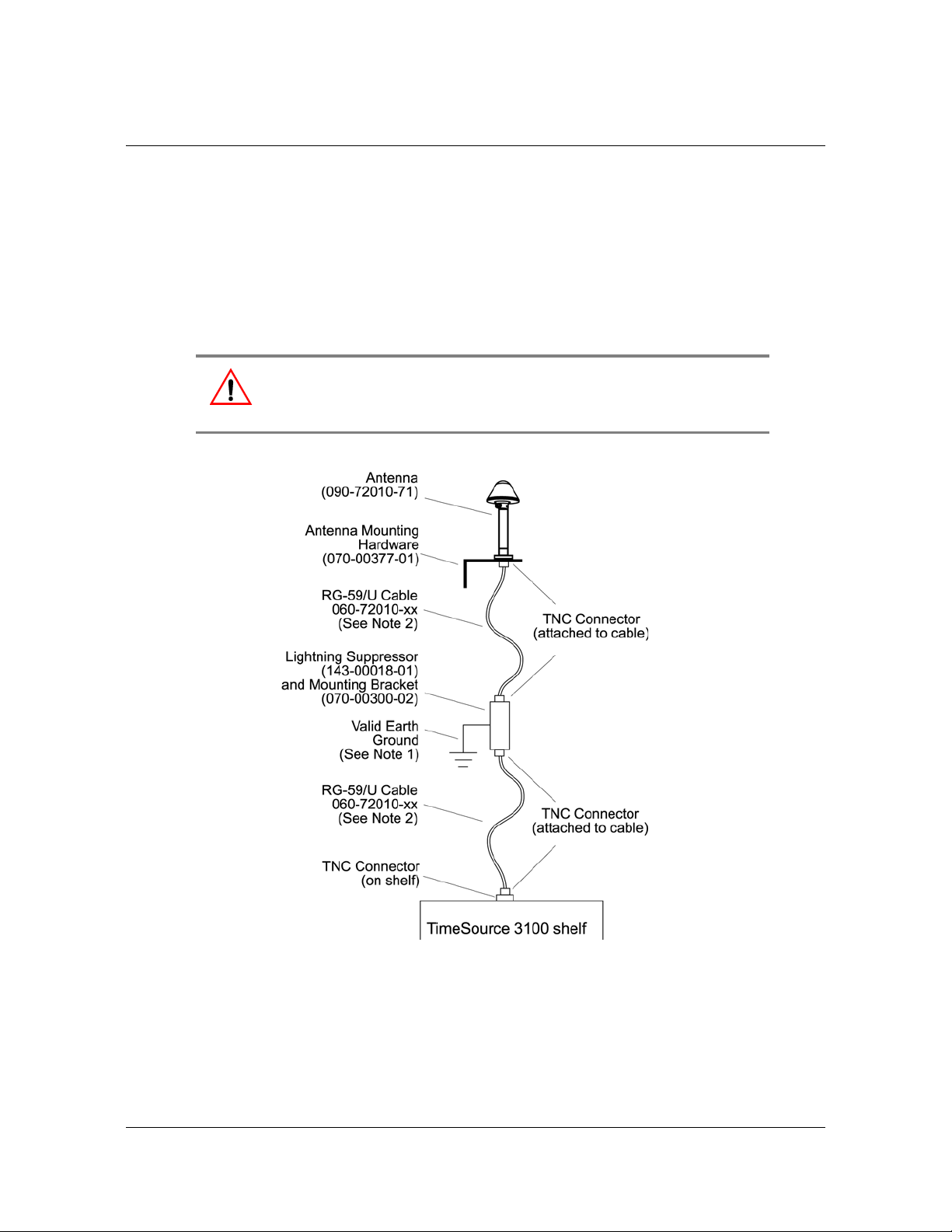
Installing the Antenna
These installation procedures are to be used in support of local company
procedures and the Installation Job Specification.
Prior to installing the antenna, the site, antenna location, lightning suppressor
location, cable route, and all other details should be planned as described in
Antenna Location Guidelines, on page 33.
To install the antenna, refer to Figure 3-1, and perform the procedure that follows.
Warning: To prevent possible lightning-induced damage, install the
lightning suppressor away from electrical devices or cabling that may
induce arcing.
Chapter 3 Installing the TimeSource 3100
Installing the Antenna
Figure 3-1. Antenna-to-Shelf Cabling
097-72020-01 Revision K – December 2005 TimeSource 3100 User’s Guide 47
Page 48

Chapter 3 Installing the TimeSource 3100
Installing the Antenna
1. Attach the antenna mounting bracket to a 1-inch (2.5 cm) diameter pipe or wood
post.
– If you are mounting the bracket to a pipe, assemble as shown in
Figure 3-2. Slide the two V-bolts over the pipe, and through the mounting
bracket slots; then place the provided four washers and four nut s over the
V-bolts, against the mounting bracket. Leave the V-bolts loose enough to
allow for final adjustments.
Figure 3-2. Installing the Antenna Bracket on a Pipe
– If you are mounting the bracket to a wood post, assemble as shown in
Figure 3-3. Install the provided two self-tapping screws in two diagonally
positioned mounting bracket slots, and attach to the post.
Figure 3-3. Installing the Antenna Bracket on a Post
Mount the antenna and mast assembly to the “L” bracket.
2. Connect the mast to the flange using PVC glue.
48 TimeSource 3100 User’s Guide 097-72020-01 Revision K – December 2005
Page 49
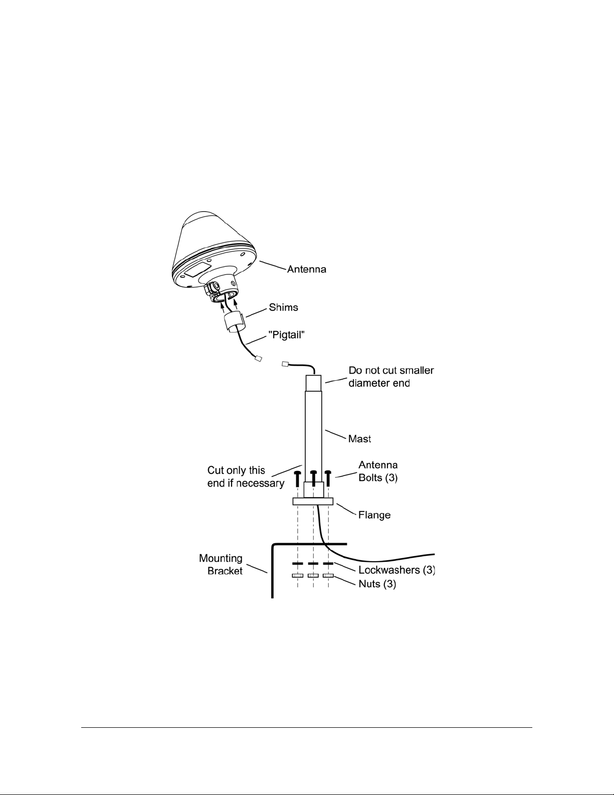
Chapter 3 Installing the TimeSource 3100
3.
Feed an RG58 (060-72010-xx) cable through the bottom of the mast as illustrated.
Installing the Antenna
See Antenna Cable Choices, on page 37 for specific cable lengths.
4. Connect the cable to the antenna “pigtail” and pull the cable back through the mast.
5. Mount the antenna to the mast using the supplied shims.
6. Mount the antenna and mast assembly to the “L” bracke t using the supplied nut s,
bolts, and washers, as shown in Figure 3-4.
Figure 3-4. Attaching the Antenna to the Bracket
7. Using a plumb line or bubble level, ensure the antenna is within 5° of vertical
(perpendicular to the horizon), and tighten the mounting bracket bolts.
097-72020-01 Revision K – December 2005 TimeSource 3100 User’s Guide 49
Page 50

Chapter 3 Installing the TimeSource 3100
Installing the Antenna
8. Bolt the lightning suppressor mounting plate to a flange that is att ached to a valid
earth ground. The roof ring ground system, a Central Office grounding plate, and
building structural steel are examples of valid earth ground points. If the
mounting plate cannot be bolted to a valid earth ground, bolt the mounting plate
to a point within 15 feet (4.6 m) of the chosen valid earth ground. If the mou nting
plate is to be installed in a nonmetallic junction box, perform the installation and
bolt the assembly near the chosen valid earth ground.
Note: A junction box must have inside dimensions of 7 cm by
7 cm by 4 cm to hold the mounting plate and attached
components.
9. Assemble the lightning suppressor as shown in Figure 3-5.
Figure 3-5. Assembling the Lightning Suppressor
10.Install 1.5-inch (3.8 cm) nonmetallic conduit from the antenna to the lightning
suppressor, and from the lightning suppressor to the cable entrance into the
building.
11.Install a user-supplied bracket, preferably non-metallic, to support the vertical
section of conduit to the antenna.
50 TimeSource 3100 User’s Guide 097-72020-01 Revision K – December 2005
Page 51

Chapter 3 Installing the TimeSource 3100
Installing the Shelf
12.Route the antenna cable through the conduit, and connect the cable to the
lightning suppressor. See Antenna Cable Choices, on page 37 for specific cable
lengths. Connect the other end of the cable to the antenna.
13.If the lightning suppressor is not mounted directly to a valid earth grou nd, crimp a
length of 4.115 mm (6 AWG) ground cable to the two-hole terminal, slide the
terminal over two of the three threaded posts on the lightning suppressor
mounting plate, and attach the terminal to the mounting plate with two KEPS
nuts. Use the two posts that allow the least bending of the cable.
14.Connect an RG58 (060-72010-xx) cable between the lightning suppressor and
the TimeSource 3100. See Antenna Cable Choices, on pa ge 37 for specific cable
lengths.
15.Install fire-stopping material in all holes opened in the roof and/or walls during
this procedure.
16.Check all connections for tightness to prevent arcing and intermittent operation.
17.Coat all exposed connectors with an electrically conductive antioxidant
compound (e.g. Kopr-Shield spray).
Installing the Shelf
Installing Output Modules
Warning: To prevent possible ESD damage to the circuitry on the
plug-in circuit board, be sure to wear a properly grounded ESD wrist
strap when making connections to the connector panel.
If an 8 E1 output module, an 8 mixed El/T1 output module, a 4 IRIG-B output
module, or a 2 ESCIU port module is supplied with the system, install the module as
follows:
1. Remove the shelf cover to access the shelf connector panel.
2. Plug the module into the OPTIONS I/O connector on the connector panel (refer
to Figure 3-6).
3. Align the three spring-loaded screws on the module with the threaded holes on
the panel.
4. Use a medium flat-blade screwdriver to lock each screw in place. Torque the
screws evenly to prevent skewing the module.
097-72020-01 Revision K – December 2005 TimeSource 3100 User’s Guide 51
Page 52

Chapter 3 Installing the TimeSource 3100
Installing the Shelf
Figure 3-6. Location of the Options I/O Connector
Rack Mounting
The shelf is shipped with the ears positioned for ETSI 53.5 cm mounting
(Figure 12A). For 48 cm racks, the shelf can be positioned to the rear of the rack rail
for flush mounting (Figure 12B) or to the front of the rack rail for 12.7 cm offset
mounting (Figure 12C).
Position the mounting ears, as shown in Figure 3-7. Mount the shelf in the rack
according to standard company practices.
52 TimeSource 3100 User’s Guide 097-72020-01 Revision K – December 2005
Page 53

Chapter 3 Installing the TimeSource 3100
Making Cable Connections
Figure 3-7. Rack Mounting Options
Making Cable Connections
Warning:
To prevent possible ESD damage to the circuitry on the plug-in circuit
board, be sure to wear a properly grounded ESD wrist strap when
making connections to the connector panel.
Do not remove, peel, pierce, or violate the integrity of the plastic
overlay bonded to the faceplate on the plug-in circuit card. The
overlay is an integral part of the ESD protection on the card.
The Craft connection is made at the shelf front panel. All other connections are
made at the shelf connector panel. To access the shelf connector panel, remove its
cover.
097-72020-01 Revision K – December 2005 TimeSource 3100 User’s Guide 53
Page 54
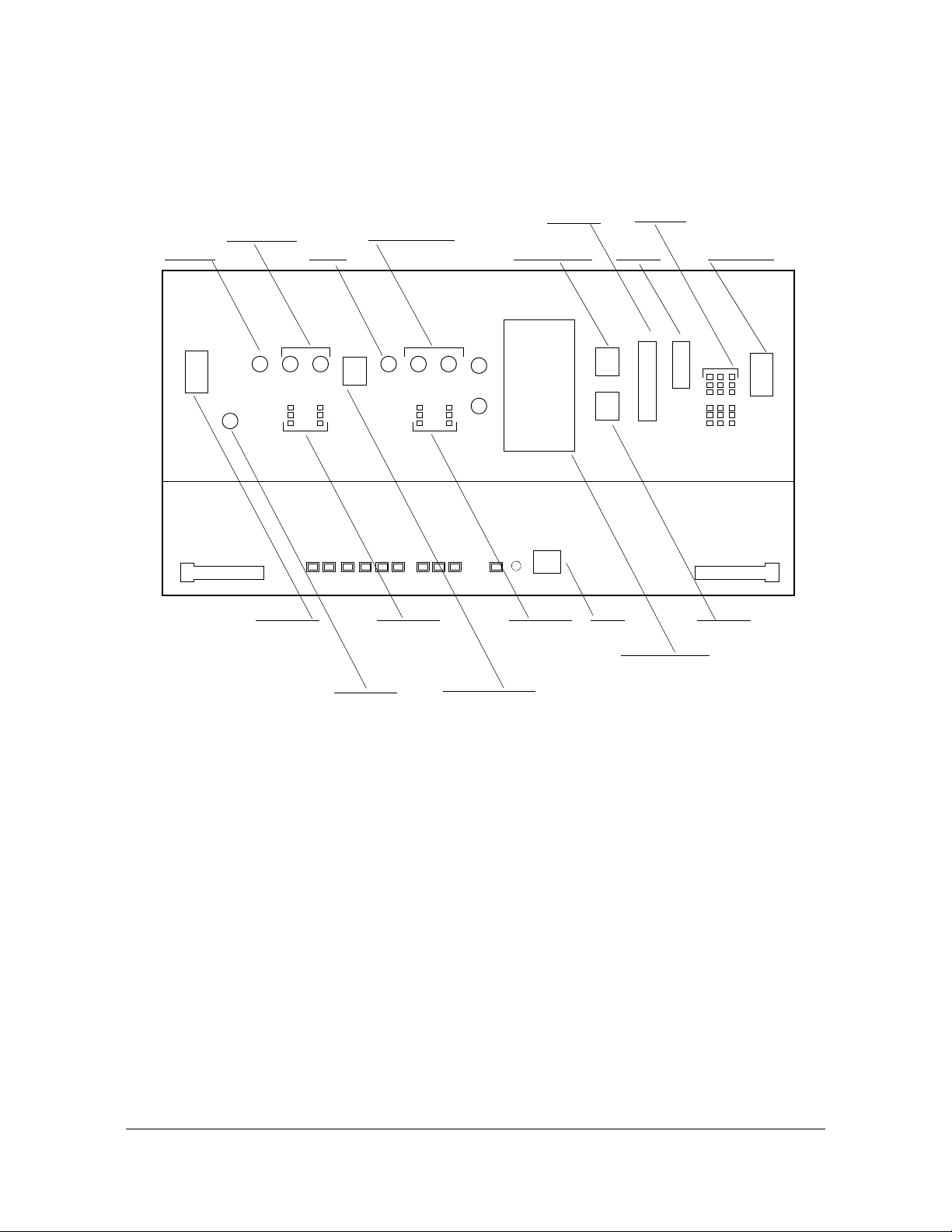
Chapter 3 Installing the TimeSource 3100
Making Cable Connections
Figure 3-8 shows the connectors on the front panel and connector panel. All
connectors can be located using these illustrations.
10 MHz
output
E1 outputs
A & B
(BNC)
Battery B
& frame
ground
(TB2)
1 pps
output
E1 inputs A & B
(BNC)
E1 outputs
A & B
(wire-wrap)
GPS
antenna
input
Time of day
E1 inputs
A & B
(wire-wrap)
Expansion Bus
(Reserved for
future use)
Com
port 1
4 IRIG-B TOD outputs (BNC) or
Alarms
Com
port 2
Craft
Output Module:
8 E1 outputs (BNC or
wire-wrap) or
2 ESCIU ports (BNC or
wire-wrap) or
8 mixed E1/T1 outputs
(wire-wrap)
Battery A
& frame
ground
(TB1)
Ethernet
Figure 3-8. Connector Panel and Front Panel Connectors
Frame Ground
Frame ground enters through the four-position power terminal blocks labeled TB1
and TB2. Figure 3-9 shows the location of the terminal blocks, and Figure 14 shows
the terminal block connections.
54 TimeSource 3100 User’s Guide 097-72020-01 Revision K – December 2005
Page 55

Chapter 3 Installing the TimeSource 3100
Figure 3-9. Terminal Block Connections on the Connector Panel
Making Cable Connections
Ensure the frame ground wires are long enough to reach from the shelf connector
panel to the frame ground connection. Use one 1.47 mm (16 A WG) gre en insulated
wire to connect the FRM terminal of power terminal block TB1 to the frame ground,
and use another 1.47 mm (16 AWG) green insulated wire to connect the FRM
terminal of TB2 to frame ground.
Make the ground connection, following one of the methods described below,
depending on whether a ground rod is installed:
With a ground rod:
Solder the connection to the 4.115 mm (6 AWG) frame ground rod that is run
vertically on each side of the rack, if provided. Two methods are acceptable:
Crimp an appropriate-size spade lu g to the 1.47 mm (16 A WG) wire, bend the lug
around the frame ground rod, and solder.
Strip enough insulation from the 1.47 mm (16 AWG) wire to permit three
complete turns around the frame ground rod, and solder.
Note: To avoid a cold solder connections, use at least a 25-W
soldering iron to ensure that the frame ground rod is heated
sufficiently.
Without a ground rod:
Crimp an appropriate spade lug to the ground wire from each terminal block, and
screw the lug to a screw hole on the rack. Remove the paint and sand the area
around the screw hole to ensure proper conductivity. Coat the connection with an
electrically conductive antioxidant compound, for example, Kopr-Shield spray.
097-72020-01 Revision K – December 2005 TimeSource 3100 User’s Guide 55
Page 56
Chapter 3 Installing the TimeSource 3100
Making Cable Connections
Making Power Connections
Caution: To avoid possible shock, protective fusing must be provided
as part of the installation. This equipment is intended for installation in
a restricted access location.
Caution: To avoid possible shock, do not apply power to the
TimeSource 3100 shelf before instructed in this procedure. Before
connecting the power cables to the TimeSource 3100, ensure the
fuses are removed from the fuse panel that supplies power to the
power cables.
The –48 volt DC battery enters through the four-position power terminal blocks
labeled TB1 and TB2. Figure 3-8 shows the location of the terminal blocks, and
Figure 3-9 shows the terminal block connections.
Ensure the power wires are long enough to reach from the shelf connector panel to
the office battery source connection. Use two 1.47mm (1 6 AWG) stranded wires for
the power connection, one with red insulation (BATT), and the other with black
insulation (RTN).
Note: Input power is reverse polarity protected; there are no user
replaceable fuses in the TimeSource 3100.
Connect the power wires with red insulation to the BATT wire receptacles on TB1
and TB2. Connect the power wires with black insulation to the RTN wire receptacles
on TB1 and TB2.
Note: Two separate office battery supplies (battery A and battery B)
are recommended. If separate office battery supplies are not
available, connect a single office battery to both input s (TB1 and TB2)
to avoid a standing battery-failure alarm.
Making GPS Antenna Connections
Connect the coaxial cable from the lightning suppressor to the TNC connector
labeled GPS ANT. See Figure 3-8 for the connector location.
Making 10 MHz Output Connections
Connect an RG-58 coaxial cable from the connector labeled 10 MHz to the
equipment that will use the 10 MHz output signal. See Figure 3-8 for the connector
location.
56 TimeSource 3100 User’s Guide 097-72020-01 Revision K – December 2005
Page 57

Chapter 3 Installing the TimeSource 3100
Making Cable Connections
Making E1 or Analog Synchronization Output Connections
Connect the E1 or analog synchronization outputs at the wire-wrap pins or BNC
connectors labeled El OUT A and El OUT B. If using the wire-wrap pins, connect the
tip wire to the pins labeled T, the ring wire to the pins labeled R, and the shield to
the pins labeled S. See Figure 3-8 for the location of the connectors and pins, and
Figure 3-10 for the wire-wrap connections.
Notes:
1. For wire-wrap connections, the shield pin is provided to ground
the cable shield at the shelf, if required. Normally, the shield is
grounded at the source. Grounding the shield at both ends is not
recommended.
2. A BNC connector can be used for one output, and a wire-wrap
connector can be used for the other output, but do not use the
BNC and wire-wrap connectors of the same output
simultaneously. For example, a BNC connector can be used for
output A and the wire-wrap pins for output B, but do not use the
output A BNC connector with the output A wire-wrap connector
Warning: To avoid possible equipment damage, do not connect the
El output line directly to a point outside the building. The El output
circuits do not provide lightning protection.
Figure 3-10. E1 or Analog Output Wire-Wrap Connections
Making 1 PPS Output Connections
Connect an RG-58 coaxial cable from the connector labeled TTL PPS to the
equipment that will use the 1 pulse-per-second TTL output signal. See Figure 3-8
for the connector location.
097-72020-01 Revision K – December 2005 TimeSource 3100 User’s Guide 57
Page 58
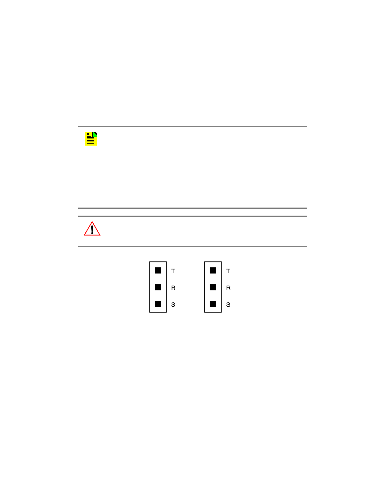
Chapter 3 Installing the TimeSource 3100
Making Cable Connections
Connecting E1 or Analog Reference Inputs
E l or analog reference inputs, traceable to an independent Stratum 1 source, can
be used in the output ensemble. Also, the performance of one or two references can
be monitored. In either case, connect reference inputs to the wire-wrap pins or BNC
connectors labeled SPAN IN A and SPAN IN B. If using the wire-wrap pins, connect
the tip wire to the pin labeled T, the ring wire to the pin labeled R, and the shield (if
connected at the TimeSource 3100) to the pin labeled S. See Figure 3-8 for the
location of the connectors and pins, and Figure 3-11 for the wire-wrap connection s..
Notes:
1. The shield pin is capacitively coupled to ground. No rm ally, the
shield is grounded at the source. Grounding the shield at both
ends is not recommended.
2. A BNC connector can be used for one output, and a wire-wrap
connector can be used for the other output, but do not use the
BNC and wire-wrap connectors of the same output
simultaneously. For example, a BNC connector can be used for
output A and the wire-wrap pins for output B, but do not use the
output A BNC connector with the output A wire-wrap connector
Warning: To avoid possible equipment damage, do not connect the
El output line directly to a point outside the building. The El output
circuits do not provide lightning protection.
Figure 3-11. E1 or Analog Output Wire-Wrap Connections
Connecting Remote Oscillator Inputs
If using the remote oscillator outputs, follow the instructions below.
Refer to Chapter 2, Engineering & Ordering to determine if an isolator kit is required.
58 TimeSource 3100 User’s Guide 097-72020-01 Revision K – December 2005
Page 59

Chapter 3 Installing the TimeSource 3100
Making Cable Connections
For the connection between the Time Source 3100 Shelf and the isolation module,
use the provided two 1.83 meter lengths of 50 ohm coax cables. If the TimeSource
3100 Shelf is not collocated with the DCD Shelf, and longer cables are required,
these must not exceed 15 meters, and are to be user-supplied.
Note: The isolation module must be mounted on the rack, in close
proximity to the DCD Shelf, whether or not the TimeSource 3100 is
installed in a collocated or non-collocated location from the DCD
Shelf. Attaching the isolation module (to the rack) grounds the
module to rack frame ground. Grounding the module to rack frame
ground is required if the TimeSource 3100 is located at a distance
less than 1.83 meters from the DCD Shelf.
DCD Shelf with Isolation Module
To install the isolation module, perform Procedure C.
1. On the rear of the DCD rack, check either side of th e DCD shelf, directly above or
below the shelf, for a location to mount the isolation module. Mount the module to
the rack, using the two provided screws.
Note: Due to distance constraints, the module must be placed no
more than 0.61 meter from the following connectors:
OSC A/B OUT connectors on the rear of the DCD-519 and
DCD-523 (Rev. D or earlier) master shelves
5 MHZ OUTPUT A/B connectors on the DCD-ST2 master shelf
J35 and J36 connectors on the DCD-419 master shelf (Rev. D or
later)
2. Use the provided 0.61 meter coax cable to connect from the appropriate A
connector on the DCD Shelf backplane to the TO DCD SHELF end of the
isolation module (refer to Table 3-1 and Figure 3-12).
3. Use the 1.83 meter coax cable to connect the REM OSC A connector on the
TimeSource 3100 Shelf to the TO LPR end of the isolation module (refer to
Figure 3-12).
Table 3-1. DCD Connections to the TimeSource 3100
From DCD Shelf
DCD Shelf Type
Connector Label
To TimeSource 3100
Connector
DCD-ST2
097-72020-01 Revision K – December 2005 TimeSource 3100 User’s Guide 59
J24 5 MHz OUTPUT A REM OSC A
J25 5 MHz OUTPUT B REM OSC B
Page 60
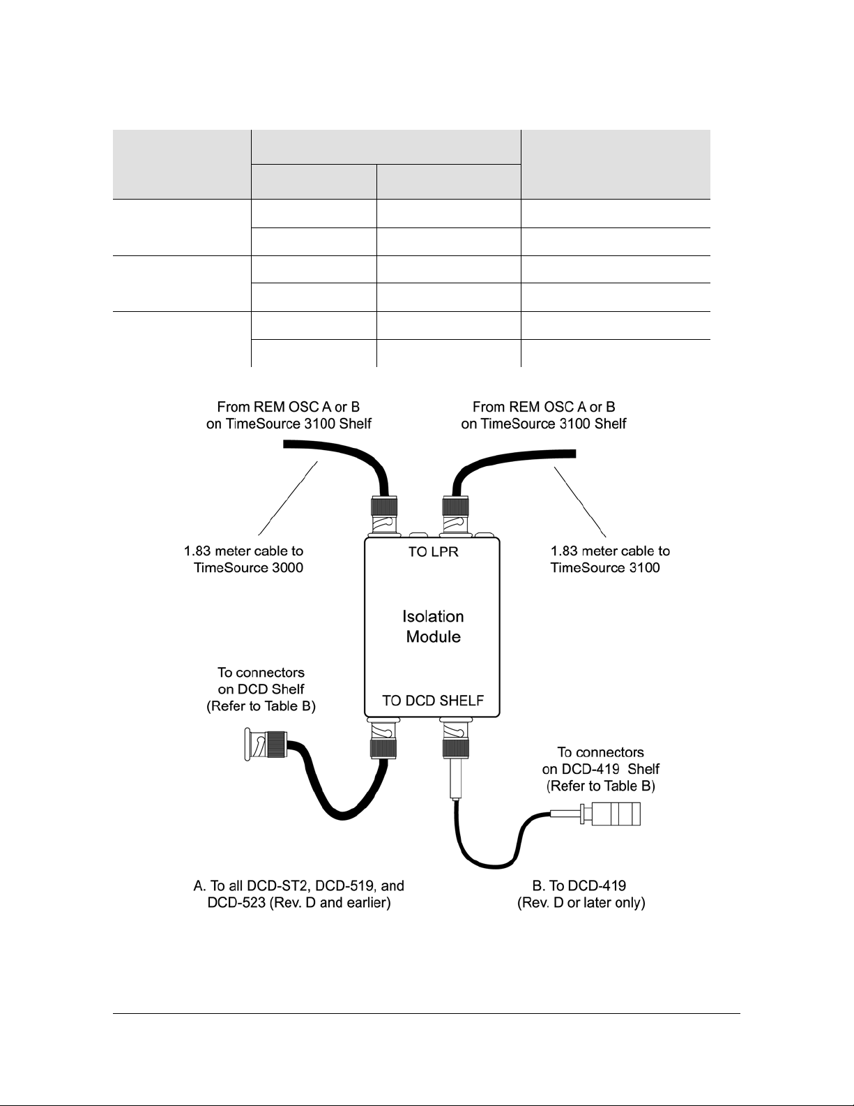
Chapter 3 Installing the TimeSource 3100
Making Cable Connections
Table 3-1. DCD Connections to the TimeSource 3100 (Continued)
DCD Shelf Type
DCD-419
DCD-523
DCD-519
From DCD Shelf
Connector Label
To TimeSource 3100
Connector
J35 Not Labeled REM OSC A
J36 Not Labeled REM OSC B
J61 OSC A OUT REM OSC A
J62 OSC B OUT REM OSC B
J44 OSC A OUT REM OSC A
J45 OSC B OUT REM OSC B
Figure 3-12. DCD Shelf, Isolation Module, and TimeSource 3100 Connections
60 TimeSource 3100 User’s Guide 097-72020-01 Revision K – December 2005
Page 61
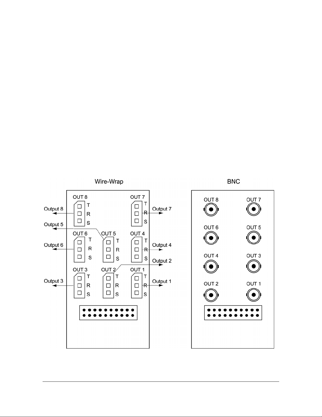
Chapter 3 Installing the TimeSource 3100
Making Cable Connections
DCD Shelf without Isolation Module
If an isolation module is not required, use two 50 ohm coax cables to make the
connections to the DCD Shelf. Cables must not exceed 15 meters, and must be
purchased separately or are to be user-supplied.
Source Other than DCD Shelf
If an isolator kit is not required, connect an RG-59/U coaxial cable from a 5 MHz or
10 MHz remote oscillator to the connector labeled REM OSC A. Connect another
RG-59/U coaxial cable from a remote oscillator of the same frequency to the
connector labeled REM OSC B. Both remote oscillators must be the same
frequency, and a minimum of Stratum 2 (rubidium oscillator) quality. See Figure 13.
for the connector locations.
Installing a Module for Additional E1 or Analog Outputs
Connect the optional eight E1 or analog outputs with the wire-wrap or BNC output
module. See Figure 3-8 for the connector location, and Figure 3-13 for the
connections.
Figure 3-13. Eight E1 or Analog Output Connections
097-72020-01 Revision K – December 2005 TimeSource 3100 User’s Guide 61
Page 62

Chapter 3 Installing the TimeSource 3100
Making Cable Connections
Installing the Mixed E1/T1 Output Module
Connect the optional eight mixed El/T1 outputs with the wire-wrap output module.
See Figure 3-8 for the connector location, and Figure 3-14 for the connections.
Figure 3-14. Eight Mixed E1/T1 Output Connections
Installing the IRIG-B TOD Output Module
Connect the four optional IRIG-B TOD outputs with the IRIG-B output module. See
Figure 3-8 for the connector location, and Figure 3-15 for the connections.
62 TimeSource 3100 User’s Guide 097-72020-01 Revision K – December 2005
Page 63
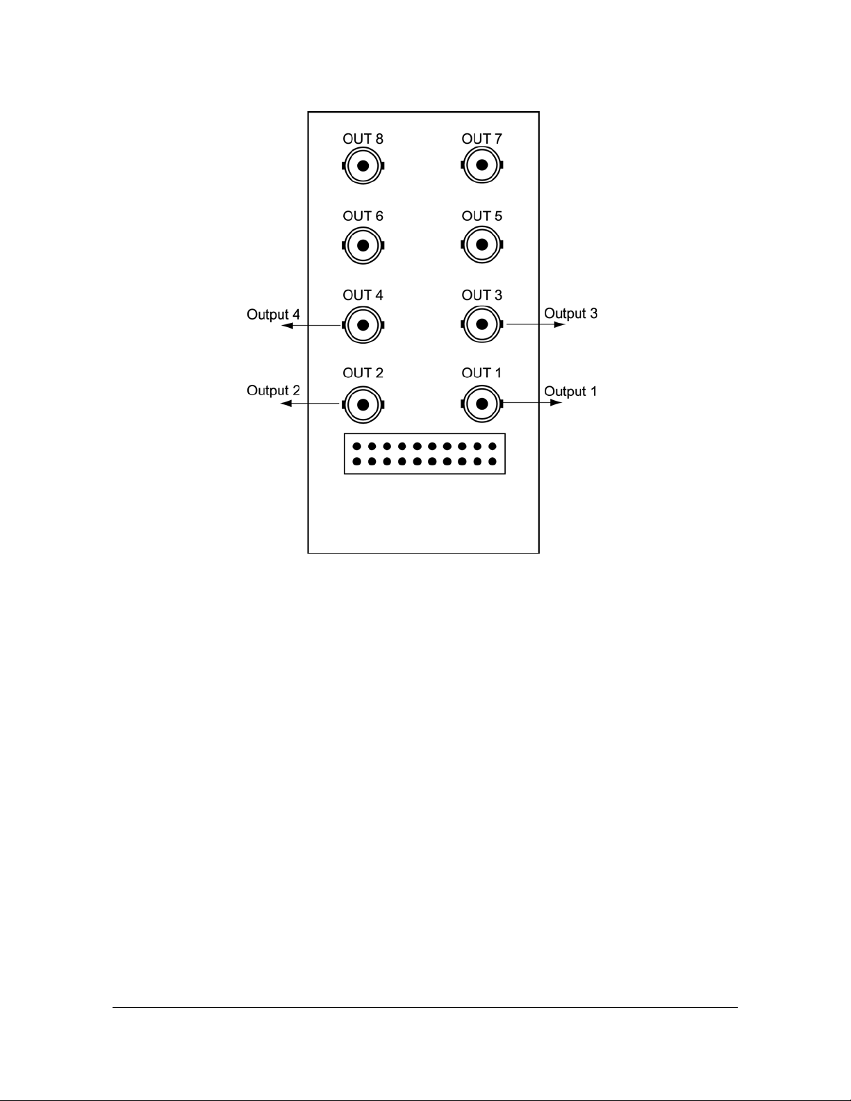
Chapter 3 Installing the TimeSource 3100
Making Cable Connections
Figure 3-15. IRIG-B TOD Output Connections
Installing the ESCIU Port Module
The ESCIU ports (Figure 3-16) have a different function than the synchronization
outputs. Synchronization outputs provide external reference clock signals for
network elements. ESCIU ports carry El traffic, and directly synchronize the El
bitstream.The ESCIU module can synchronize 2 spans in one direction. The return
direction passes through as it is.
The ESCIU ports can connect at the digital distribution frame (DDF). The network
elements receiving the ESCIU output signal must be able to receive El signals that
conform to CCITT G.703 paragraph 6 specifications.
A bypass relay directs the E1 traffic a round the ESCIU circuits to maint ain continuity
on the spans if a fault occurs.
097-72020-01 Revision K – December 2005 TimeSource 3100 User’s Guide 63
Page 64

Chapter 3 Installing the TimeSource 3100
Making Cable Connections
Figure 3-16. Connector Layout of ESCIU Modules
Cutover Procedures for Out-of-Service Equipment
If DDF access jack sets are not cabled to the ESCIU module, the following
out-of-service cutover procedure must be used. Consult the local company
Installation Job Specifications to ensure that the network element to be re-timed is
connected to the ESCIU module correctly. Refer to Figure 3-17 for the following
procedure:
1. Remove from service (turn down) the traffic trunks on the E1 system to be
cutover to the ESCIU module.
2. Remove the existing cabling in both directions between the transmit (OUT) and
receive (IN) terminals of the NEs that will connect to the ESCIU module.
3. In the direction not to be synchronized by the ESCIU module, connect new
cables from the ESCIU module RTNx IN connector to the NE transmit (OUT)
terminal, and connect from the ESCIU module RTNx OUT connector to the NE
receive (IN) terminal.
4. In the direction to be synchronized by the ESCIU module, connect new cables
from the ESCIU module IN connector to the NE transmit (OUT) terminal, and
connect from the ESCIU module OUT connector to the NE receive (IN) terminal.
5. Verify that there are no alarms on the NEs on the E1 system. If there are ala rms,
recheck the new cabling between the NEs and the ESCIU module.
6. Restore (turn up) the traffic trunks to service.
64 TimeSource 3100 User’s Guide 097-72020-01 Revision K – December 2005
Page 65

Chapter 3 Installing the TimeSource 3100
Making Cable Connections
Figure 3-17. ESCIU Cutover without Jacks (Out-of-Service)
Cutover Procedures for In-Service Equipment
If standard digital signal level access jack sets, such as DDF or DSX-1 jacks, were
cabled to the ESCIU module, the following in-service cutover procedure must be
used. Consult the local company Installation Job Specifications to ensure that the
network element to be re-timed from the ESCIU module will be connected to the
ESCIU module A OUT terminals. Refer to Figure 3-18 for the following procedure:
1. Patch a bridging repeater from the MON jack of one NE to the IN jack of the other
NE in both directions of transmission on the E1 system to be cutover. Place a 75
Ω termination plug in the OUT jack in each direction.
2. Remove the cross-connect wiring from the OUT and IN jacks (off-normal side of
jacks) in both directions of transmission.
097-72020-01 Revision K – December 2005 TimeSource 3100 User’s Guide 65
Page 66

Chapter 3 Installing the TimeSource 3100
Making Cable Connections
3. In the direction not to be synchronized by the ESCIU module, connect new
cables from the ESCIU module RTNx IN connector to the NE transmit (OUT)
terminal, and connect from the ESCIU module RTNx OUT connector to the NE
receive (IN) terminal.
4. In the direction to be synchronized by the ESCIU module, connect new cables
from the ESCIU module IN connector to the NE transmit (OUT) terminal, and
connect from the ESCIU module OUT connector to the NE receive (IN) terminal.
5. Remove the 75 Ω (E1) termination plug from the OUT jack and p atch cor ds from
the NE IN jack. The E1 system bitstream is now going through the ESCIU
module.
6. Verify that there are no alarms on the NEs on the E1 system. If there are ala rms,
reinsert patch cords in the IN jack and the termination plugs in the OUT jack.
Recheck the cross-connect wiring just installed, and repeat Step 5.
7. Remove the remaining patch cords from the NE MON jack.
66 TimeSource 3100 User’s Guide 097-72020-01 Revision K – December 2005
Page 67

Chapter 3 Installing the TimeSource 3100
Making Cable Connections
Figure 3-18. ESCIU Cutover with Jacks (In-Service)
097-72020-01 Revision K – December 2005 TimeSource 3100 User’s Guide 67
Page 68

Chapter 3 Installing the TimeSource 3100
Making Cable Connections
Connecting the Time of Day Output
If using Time of Day Output, connect the time of day (TOD) output at the female
RJ-45 connector labeled TOD. See Table 3-8 for the connector location, and Table
3-2 for the connector pinouts.
Table 3-2. TOD Connector Pinout
Pin Signal Abbreviation Direction
1
2
3
4
5
6
7
8
Note: Pins not listed are reserved for future use.
1 pps A TOD PPS + From TimeSource 3100
1 pps B TOD PPS – From TimeSource 3100
12 V power source TOD P12V —
Receive data B TOD RXD – To TimeSource 3100
Receive data A TOD RXD + To TimeSource 3100
Circuit ground TOD GND —
Transmit data A TOD TXD + From TimeSource 3100
Transmit data B TOD TXD – From TimeSource 3100
If the device receiving the time code (for example, a Cisco router) accepts an
RS-232 cable instead of an RS-422 cable, follow Procedure D to install the
RJ-45-to-DB-25 TOD converter.
Note: Before you perform the following procedure, ensure that the
appropriate Cisco router or NTP type 4 compatible device is installed,
and power applied, per manufacturer's instructions.
1. Secure the provided mounting plate to the RS-422–to–RS-232 TOD converter
using the two provided screws. The plate may be attached to the top or front of
the converter, depending on the desired surface (for example, a rack or cabinet)
to which the converter will be mounted (see Figure 3-19).
Notes:
1. Due to distance constraints, the converter must be placed no
more than 305 m from the TimeSource 3100 Shelf, and no more
than 15 m from the device receiving the time code.
2. The converter dimensions are 7.5 cm by 3.8 cm by 2.5 cm.
3. The mounting plate dimensions are 7.5 cm by 5 cm.
2. Secure the converter to the desired surface, using the slots in the plate and
user-supplied bolts.
68 TimeSource 3100 User’s Guide 097-72020-01 Revision K – December 2005
Page 69
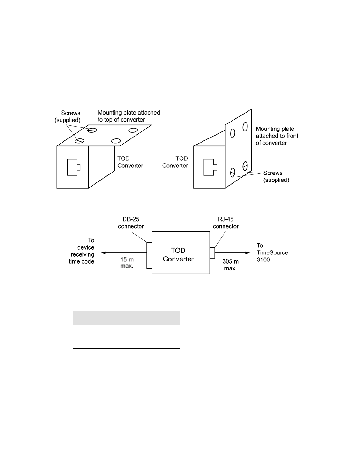
Chapter 3 Installing the TimeSource 3100
Making Cable Connections
3. Install a user-supplied Category 5 four-pair RS-422 cable with RJ-45 connectors
on each end, between the T imeSource 3100 Shelf and th e converter (see Figure
3-20).
4. Install a user-supplied RS-232 cable, with DB-25 connectors on each end,
between the converter and the device receiving the time code (see Figure 3-20).
See Table 3-3 for the DB-25 connector pinouts.
Figure 3-19. RS-422 to RS-232 TOD Converter Mounting Plate
Figure 3-20. RJ-45 to DB-25 TOD Converter Connections
Table 3-3. Converter DB-25 Connector Pinout
Pin Signal
1
3
5
7
Frame ground
Data output (RS-232)
1 pps (RS-232)
Signal ground
Note: Pins not listed are reserved for future use.
097-72020-01 Revision K – December 2005 TimeSource 3100 User’s Guide 69
Page 70

Chapter 3 Installing the TimeSource 3100
Making Cable Connections
Making Ethernet Connections
Connect the Ethernet cable from the network to the 10base-T Ethernet connector
labeled E-NET. See Table 3-8 for the connector location, and Table 3-4 for the
connector pinouts.
Table 3-4. Ethernet RJ-45 Connector Pinout
Pin Signal Abbreviation Direction
1 Transmit data + TXD + From TimeSource 3100
2 Transmit data – TXD – From TimeSource 3100
3 Receive data + RXD + To TimeSource 3100
6 Receive data – RXD – To TimeSource 3100
Note: Pins not listed are reserved for future use.
Connecting to Communication Port 1
To provide an RS-232 link for TL1 command access to the TimeSource 3100,
connect to port 1 at the female 25-pin D connector labeled COM 1. See Figure 3-8
for the location of the connector. See Table 3-5 for the connector pinouts.
Note: The COM 1 connector transmits data on pin 2 and receives
data on pin 3. Be sure the other equipment receives data from the
transmitting pin, and transmits data to the receiving pin.
Table 3-5. COM 1 Connector Pinout
Pin Signal Abbreviation Direction
2 Transmit data TXD From TimeSource 3100
3 Receive data RXD To TimeSource 3100
4 Request to send RTS From TimeSource 3100
5 Clear to send CTS To TimeSource 3100
6 Data set ready DSR To TimeSource 3100
7 Signal ground GND —
20 Data terminal ready DTR From TimeSource 3100
Note: Pins not listed are reserved for future use.
70 TimeSource 3100 User’s Guide 097-72020-01 Revision K – December 2005
Page 71

Chapter 3 Installing the TimeSource 3100
Making Cable Connections
Connecting to Communication Port 2
To provide an RS-232 link for TL1 command access to the TimeSource 3100,
connect to port 2 at the female 9-pin D connector labeled COM2. See Figure 3-8 for
the location of the connector, and Table 3-6 for the connector pinouts.
Note: The COM 2 connector transmits data on pin 2 and receives
data on pin 3. Be sure the other equipment receives data from the
transmitting pin, and transmits data to the receiving pin.
Table 3-6. COM 1 Connector Pinout
Pin Signal Abbreviation Direction
2 Transmit data TXD From TimeSource 3100
3 Receive data RXD To TimeSource 3100
5 Signal Ground GND —
6 Data terminal ready DTR From TimeSource 3100
7 Clear to send CTS To TimeSource 3100
8 Request to send RTS From TimeSource 3100
Note: Pins not listed are reserved for future use.
Connecting Alarm Outputs
Connect the TimeSource 3100 alarms to the office alarm panel at the critical (CR),
major (MJ), and minor (MN) wire-wrap pins. See Figure 3-8 for the location of the
alarm pins, and Figure 3-21 for the connections.
Connect at the upper group of pins (AUD) for audible alarms and at the lower group
of pins (VIS) for visible alarms. Connect the alarm circuit between the NO and C
pins for normally open contacts, or between the NC and C pins for normally closed
contacts.
097-72020-01 Revision K – December 2005 TimeSource 3100 User’s Guide 71
Page 72

Chapter 3 Installing the TimeSource 3100
Making Cable Connections
Figure 3-21. Alarm Connector
Making Craft Port Connections
To provide an RS-232 link for TL1 command access to the TimeSource 3100,
connect to the craft port at the female RJ-45 connector labeled Craft on the front
panel. A Craft-port-to-PC cable is supplied with the TimeSource 3100 for making
this connection. See Figure 3-8 for the location of the connector, and Table 3-7 for
the connector pinouts.
Note: The Craft connector transmits data on pin 2 and receives data
on pin 3. Be sure the other equipment receives data from the
transmitting pin, and transmits data to the receiving pin.
Table 3-7. COM 1 Connector Pinout
Pin Signal Abbreviation Direction
2 Transmit data TXD From TimeSource 3100
3 Receive data RXD To TimeSource 3100
5 Signal ground GND —
6 Data terminal ready DTR From TimeSource 3100
Note: Pins not listed are reserved for future use.
72 TimeSource 3100 User’s Guide 097-72020-01 Revision K – December 2005
Page 73

Powering Up the Shelf
To power the TimeSource 3100, follow the steps in this section. Before starting this
procedure, be sure the antenna, shelf, and all connections appropriate for this
installation have been installed, and that the host computer is set to communicate
with the TimeSource 3100.
You need the following equpment to perform this procedure:
Grounding wrist strap
Digital multimeter (Fluke 77 or equivalent)
Laptop computer with communications software (e.g., Windows Hyperterminal,
ProComm Plus, CrossTalk)
Prepare to Apply Power
1. Start a VT100 terminal mode session on the computer connected to the
TimeSource 3100. Use a communication program that supports the Y-modem
protocol (such as Hyperterminal, or a commercial package such as PROCOMM
PLUS or CrossTalk).
Chapter 3 Installing the TimeSource 3100
Powering Up the Shelf
2. Set the communication program to communicate with the port that is connected
to the TimeSource 3100.
3. Set the RS-232 communication parameters to 8 data bit s, no parity bit, 1 sto p bit,
and 9600 baud.
4. Connect the computer communication port to the COM1, COM2, or Craft port on
the TimeSource 3100. A craft port-to-PC communication cable is provided in the
hardware kit for this purpose.
5. Ensure that the TimeSource 3100 plug-in card is not installed in the shelf.
6. Ensure that all fuses that supply power to the TimeSource 3100 shelf are
removed from the fuse panel.
7. At the shelf end of the battery leads, use the multimeter to measure the voltage
between the following:
Test Point Test Point Result
–48V A lead –48V B lead 0 V
–48V A lead TB1: RTN A 0 V
–48V A lead TB1: GND 0 V
–48V B lead TB2: RTN B 0 V
–48V B lead TB2: GND 0 V
8. Attach a grounding wrist strap to the wrist, and plug the other end into the ground
jack at the upper-right corner of the front of the plug-in card.
097-72020-01 Revision K – December 2005 TimeSource 3100 User’s Guide 73
Page 74

Chapter 3 Installing the TimeSource 3100
Powering Up the Shelf
9. Pull out the latching levers at each end of the front panel of the T imeSource 3100
card so that the levers are pointing directly out from the front panel.
10.Push the card into the shelf until the latching levers begin to move in.
11.Push the latching levers flat against the front panel to complete the card
insertion.
12.Tighten the knurled screw above each latching lever to secure the card in the
shelf.
13.Replace the connector panel cover.
14.Unplug and remove the grounding wrist strap.
Apply Power to the Shelf
15.Install the battery source fuse in the rack fuse bay that supplies power to the
TimeSource 3100. The TimeSource 3100 enters its warm-up mode when power
is applied. During the warm-up period, the following conditions exist:
– Status GPS lamp is green
– Status SYS lamp is off
– E1 outputs are squelched, sending AIS (factory setting), or sending an
SSM message, as specified in the ED-EQPT command
– Optional eight T1 outputs (if equipped) are squelched, sending AIS
(factory setting), or sending an SSM message, as specified in the
ED-EQPT command
– Optional four IRIG-B outputs (if equipped) are squelched
– 10 MHz and 1 pps outputs are on (unreliable while Status SYS lamp is off)
– TOD output is not enabled (factory setting)
Notes:
1. The CRIT lamp and other alarm indication lamps may light. The
host computer may display transient and standing alarm
condition messages. Ignore alarms while the Status SYS lamp is
off during warm up, unless alarms apply to inputs and outputs
that were previously entered.
2. TL1 commands may be entered during warm-up to enable input s
and outputs, and to set system parameters.
Establish a Connection to the Shelf
16.Use the Activate User command to log onto the system.
ACT-USER::TELECOM:<ctag>::TS3000!!;
74 TimeSource 3100 User’s Guide 097-72020-01 Revision K – December 2005
Page 75

Chapter 3 Installing the TimeSource 3100
Powering Up the Shelf
17.If UTC time is desired, skip to Step 18. If local time is desired, use the Edit Date
command to set the date and time.
ED-DAT:::<ctag>::yyyy-mm-dd,hh-mm-ss:MODE=LOCAL;
where:
yyyy = year (1998 to 2096)
mm = month (mm = 01 to 12)
dd = day in (dd = 01 to 31)
hh = hours (hh = 00 to 23)
mm = minutes (mm = 00 to 59)
ss = seconds (ss = 00 to 59)
Example command to set local time:
ED-DAT:::123::2000-06-15,14-25-00:MODE=LOCAL;
18.If UTC time is not desired, skip to St ep 19. Use the Edit Date command to set the
system for UTC time.
ED-DAT:::<ctag>::yyyy-mm-dd:MODE=UTC;
where:
yyyy = year (yyyy = 1998 to 2096)
mm = month ((mm = 01 to 12)
dd = day (dd = 01 to 31)
Example command to set UTC time:
ED-DAT:::123::2000-06-15:MODE=UTC;
Set the Input Parameters
19.Use the Retrieve Equipment command to identify whether and how the inputs
are provisioned.
RTRV-EQPT::ALL:<ctag>;
Note: Observe those results with an <aid> of RO-a and SPAN-a. If
MONITOR=ALW appears for an input, that input has previously been
entered. If ENSEMBLER=ALW appears for an input, that input has
been set to be ensembled.
20.If the results of Step 19 indicate the remote oscillator inputs are set as desired,
skip to Step 22. Use the Enter Equipment command to monitor and/or ensemble
each remote oscillator input.
ENT-EQPT::RO-a:<ctag>:::ENSEMBLER=b;
where:
a = remote oscillator input (a = A or B)
097-72020-01 Revision K – December 2005 TimeSource 3100 User’s Guide 75
Page 76

Chapter 3 Installing the TimeSource 3100
Powering Up the Shelf
b = allow the input to be ensembled or inhibit the input from being ensembled (y =
ALW causes the input to be monitored and ensembled; y = INH cause s t he input
to be monitored, but not ensembled)
21.Use the Edit Equipment command to set the frequency of the remote oscillator
inputs.
ED-EQPT::TS3100:<ctag>:::ROFREQ=a;
where:
a = remote oscillator frequency in MHz (a = 5 or 10)
22.If the results of Step 19 indicate the E1 span inputs are set as desired, skip to
Step 25. Use the Enter Equipment command to monitor each available E1 span
input, and to specify whether those inputs are to be ensembled.
ENT-EQPT::SPAN-a:<ctag>:::ENSEMBLER=b;
where:
a = E1 span input (a = A or B)
b = allow the input to be ensembled or inhibit the input from being ensembled
(b = ALW or INH) b = ALW causes the input to be monitored and ensembled;
b = INH causes the input to be monitored, but not ensembled
Set the Output Parameters
23.Use the Edit Equipment command to set the output signal framing format for
each E1 output, and set the mode for each E1 output during an alarm.
ED-EQPT::E1-a:<ctag>:::FRAMING=b,ALMOUT=c;
where:
a = E1 output (a = A or B)
b = framing format (b = CAS, CAS4, CCS, or CCS4, or NONE for analog)
c = E1 output during alarm (c = AIS, SQUELCH, or SSM) (for SSM, framing
format must be CAS4 or CCS4)
Set the Performance Monitoring Parameters
24.If you are not using performance monitoring, skip to Step 25. Use the Initialize
Register command to reset the performance monitoring data to zero for all input
spans.
INIT-REG-EQPT::SPAN-a:<ctag>::ALL;
where:
a = SPAN input (a = A, B, or ALL)
ALL = resets all performance monitoring data
76 TimeSource 3100 User’s Guide 097-72020-01 Revision K – December 2005
Page 77

Chapter 3 Installing the TimeSource 3100
Powering Up the Shelf
Set the Ethernet Parameters
25.If you are not using Ethernet, go to Step 29. Use the Edit Equipment command
while connected to COM1, COM2, or the CRAFT port to set the IP address,
subnetwork mask, and gateway address for the current TimeSource 3100 unit,
as required for proper operation in the managed element network. (These
parameters affect all Ethernet ports. The Ethernet port should be closed and all
users logged off before issuing this command.)
ED-EQPT::TS3100:<ctag>:::IPNE=a,IPSUBNET=a,IPGATE=a;
where:
IPNE = a This unit's IP address in the form a.a.a.a (each a is an independent
value of 0 to 255)
IPSUBNET = a. Subnet mask in the form a.a.a.a (each a is an independent
value of 0 to 255)
IPGATE = a. Gateway IP address in the form a.a.a.a (each a is an independent
value of 0 to 255)
26.Ports 5001, 5002, 5003 and 5004 on the TimeSource 3100 are used as though
they were serial TL1 communication ports. The following values are set at the
factory and appear at reset:
COMPRI=ALW1 (normal communication, including autonomous messages)
MONMSG=INH (monitors only the current port for messages)
KEEPALIVE=0 (does not send a COMPLD message to keep connection open)
ENDOFTEXT=0 (does not include an end-of-text code with a TL1 message)
ECHO=ALW (echoes characters back to the sending terminal)
AUTOLOGOFF=20 (does not log off the user during inactivity)
SWCONTROL=INH (uses no flow control)
If these values require change, use the Edit Communication command to set
communications parameters for T L1 communications.
ED-COM::COM-a:<ctag>:::[MONMSG=b[,]][KEEPALIVE=c[,]]
[ENDOFTEXT=d[,]][ECHO=b[,]][COMPRI=e[,]][AUTOLOGOFF=c[,]]
[SWCONTROL=b];
where:
COM-a= User IP port (a = 5001, 5002, 5003 or 5004)
MONMSG=b Monitors messages on all ports (b=ALW), or current port (b=INH)
KEEPALIVE=c Inactive minutes until the unit sends a COMPLD message to
keep the connection from being closed (c = 0 to 255)
ENDOFTEXT=d Hex code added to responses before semicolon (d = 0
(disabled) to 9F)
ECHO=b Echoes characters received so they appear on the user's screen as
typed (b=ALW), or inhibits echo (b=INH)
097-72020-01 Revision K – December 2005 TimeSource 3100 User’s Guide 77
Page 78

Chapter 3 Installing the TimeSource 3100
Powering Up the Shelf
COMPRI=e Sets the communication port capabilities as follows:
ALW0 = normal communication, no autonomous messages
ALW1 = normal communication, autonomous messages
ALW2 = autonomous messages received, logged on or not
INH = closes connection and keeps port from use (command must go to
another port) (if the port is in use, this command also logs off the user)
AUTOLOGOFF=c Inactive minutes until the unit logs off the user, keeping the
connection open (c = 0 to 255)
SWCONTROL=b uses software (XON/XOFF) flow control (b=ALW ), or no flow
control (b=INH)
27.If you are not using an Element Manager, skip to Step 29. If you are not using a
separate port to send autonomous messages to an Element Manager, skip to
Step 28.
Use the Edit Equipment command to set the IP address and port address of the
Element Manager. Port 5550 connects to this address when the TimeSource
3100 develops a TL1 autonomous message, sends any messages, and closes
the connection. An alternate Element Manager may be set up in case port 5550
cannot make a connection to the primary Element Manager.
ED-EQPT::TS3100:<ctag>:::IPEM1=a,IPEM1PORT=b[,IPEM2=a]
[,IPEM2PORT=b][,IPINACT=c];
where:
IPEM1=a Primary Element Manager's IP address in the form a.a.a.a (each a
is an independent value of 0 to 255)
IPEM1PORT=b Primary Element Manager's Ethernet port address (b = 0 to
65535)
IPEM2=a Alternate Element Manager's IP address in the form a.a.a.a (each
a is an independent value of 0 to 255)
IPEM2PORT=b Alternate Element Manager's Ethernet port address (b = 0 to
65535)
IPINACT=c Disconnects from the Element Manager if an autonomous
message is not developed during this number of 100-ms units of inactivity (0 to
10 000, where 0 deactivates the timer)
28.An Element Manager connects to port 5551 for TL1 command and response
messages. The following values for port 5551 are set at the factory and appear at
reset:
COMPRI=ALW1 (normal communication, including autonomous messages)
MONMSG=INH (monitors only the current port for messages)
KEEPALIVE=0 (does not send a COMPLD message to keep connection open)
ENDOFTEXT=0 (does not include an end-of- text code with a TL1 message)
ECHO=b Echoes characters so they appear on the user’s screen as typed
(b=ALW) or inhibits echo (b=INH)
AUTOLOGOFF=20 (does not log off the user during inactivity)
SWCONTROL=INH (uses no flow control)
78 TimeSource 3100 User’s Guide 097-72020-01 Revision K – December 2005
Page 79

Chapter 3 Installing the TimeSource 3100
Powering Up the Shelf
If these values require change, use the Edit Communication command to set
communications parameters for T L1 communications.
ED-COM::COM-5551:<ctag>:::[MONMSG=b[,]][KEEPALIVE=c[,]]
[ENDOFTEXT=d[,]][ECHO=b[,]][COMPRI=e[,]][AUTOLOGOFF=c[,]]
[SWCONTROL=b];
where:
MONMSG=b Monitors messages on all ports (b = ALW), or current port (b = INH)
KEEPALIVE=c Inactive minutes until the unit sends a COMPLD message to
keep the connection from being closed (c = 0 to 255)
ENDOFTEXT=d Hex code added to responses before semicolon (d = 0
(disabled) to 9F)
ECHO=b Echoes characters received so they appear on the user's screen as
typed (b = ALW), or inhibits echo (b = INH)
COMPRI=e Sets the communication port capabilities as follows:
ALW0 = normal communication, no autonomous messages
ALW1 = normal communication, autonomous messages
ALW2 = autonomous messages received, logged on or not
INH = closes connection and keeps port from use (command must go to
another port) (if the port is in use, this command also logs off the user)
AUTOLOGOFF=c Inactive minutes until the unit logs off the user, keeping the
connection open (c = 0 to 255)
SWCONTROL=b Uses software (XON/XOFF) flow control (b = ALW), or no flow
control (b = INH)
Set the ESCIU Parameters
29.If you are not using ESCIU ports, skip to Step 31. Use the Edit Equipment
command to specify how the ESCIU performs during holdover:
ED-EQPT::TS3100:<ctag>:::BYPASS=a;
where:
a = E1 traffic bypasses the ESCIU circuitry (a=ALW) or continues to be
synchronized during holdover (a=INH)
30.Use the Edit Equipment command to specify how the ESCIU performs with a
Loss-of-Signal (LOS) alarm on the incoming span:
ED-EQPT::OPT-a:<ctag>::ALMOUT=b;
where:
a = Directs this command to ESCIU span 1 (a=1) or span 2 (a=2)
b = If LOS is detected on the incoming span, the ESCIU passes AIS
downstream (b=AIS) or passes the LOS downstream (b=PASSTHRU)
097-72020-01 Revision K – December 2005 TimeSource 3100 User’s Guide 79
Page 80

Chapter 3 Installing the TimeSource 3100
Powering Up the Shelf
Set the Antenna Parameters
31.If the results of Step 19 indicate the antenna cable delay and elevation mask set
are as desired, skip to Step 33. Use the Edit Equipment command to set the
length of cable between the antenna and the TimeSource 3100 Shelf. This
number should have been recorded during installation. Use the same command
to set the antenna elevation mask angle.
ED-EQPT::GPS:<ctag>:::ANTCBLDLY=x,ANTELEVMASK=y;
where:
x = antenna cable delay in meters (x = 0 to 330)
y = antenna elevation mask angle in degrees (y = 0 to 45) (see note below)
Note: The antenna elevation mask is that portion of the sky from
which the TimeSource 3100 masks out satellite signals, measured
from the horizon to the desired angle of elevation. For example, if the
sky is obstructed below 20° elevation, signals received from below
that elevation may have reflections or other anomalies. Masking
those signals may allow the receiver to acquire GPS signals more
quickly and accurately. Factory setting is 10.
Set the TOD Output Parameter
32.If you are not using the TOD output, skip to Step 33. Use the Edit Equipment
command to set the TOD output.
ED-EQPT::TS3100:<ctag>:::TOD=y;
where:
y = TOD format (y = Cisco or NTP4)
Set the Alarm Conditioning Parameter
33.Use the Edit Equipment command to allow or inhibit alarm conditioning on the
outputs. Inhibiting the alarm conditioning forces the T imeSource 3100 to continue
to output valid timing signals while in alarm. This may be useful when testing,
troubleshooting, or in installations where the outputs generated by the
TimeSource 3100 may be better than the alte rnative (for example, offices with out
additional holdover clocks in a distribution shelf).
ED-EQPT::TS3100:<ctag>:::ALMCOND=y;
where:
y = alarm conditioning of the outputs (y = ALW or INH)
80 TimeSource 3100 User’s Guide 097-72020-01 Revision K – December 2005
Page 81

Save the Setup
34.Use the Copy Memory command to copy the database from volatile to
nonvolatile memory within the TimeSource 3100.
CPY-MEM:[tid]:TS3100:<ctag>::WKG,,AUX:DATA;
Recommendation: Although the database is automatically copied to
nonvolatile memory once per hour, Symmetricom recommends that
you execute the Copy Memory command each time you change the
database.
Installing TimeWizard
The TimeWizard Software Installation application facilitates installing software
upgrades for the TimeSource 3100. This section shows how to install the
TimeWizard application and how to use TimeWizard to download software
upgrades.
Chapter 3 Installing the TimeSource 3100
Installing TimeWizard
Use this procedure to install the firmware in the TimeSource 3100 to configure the
GPS and Holdover alarms, using the TimeWizard application.
Requirements
1. A PC running Windows 95/98/NT 4.0/2000/XP.
2. The TimeSource 3100 CD provided.
Installing the Hardware
Connect the TimeSource 3100 to the PC with a serial cable.
Installing the TimeWizard Software
1. Insert the TimeSource 3100 CD into the PC’s CD-ROM drive.
If AutoRun is enabled on the PC, the CD should automatically launch the Install
Shield wizard for installation of the TimeWizard application. If InstallShield
launches, continue with Step 5. If Install Shield does not automatically launch,
continue with the next step.
2. in Windows Explorer, double-click “setup.exe” in the root directory of the CD to
start the InstallShield wizard. Follow the prompts in the InstallShield wizard to
install TimeWizard in the preferred directory.
3. From the Windows desktop, select Start
, Programs, TimeWizard to start the
TimeWizard application. When T imeW izard start s, the “T imeWizard” main screen
appears, as shown in .Figure 3-22.
097-72020-01 Revision K – December 2005 TimeSource 3100 User’s Guide 81
Page 82

Chapter 3 Installing the TimeSource 3100
Installing TimeWizard
The version of TimeWizard that is installed is indicated at the top right of the
screen. The progress indicator at the bottom of the screen shows which of the
seven screens you are currently viewing.
Note that the factory default TimeSource username of “telecom” and p assword of
“TS3000!!” appear in the Login Information area of the screen.
Figure 3-22. The TimeWizard Main Screen
4. :If the user name or password of the TimeSource have been changed, enter the
proper user name or password, otherwise, continue with the next step.
To select the high-speed download option, in which the firmware download takes
place at approximately 12 times the default speed of 9600 baud, select the Use
High Speed (115K baud) check-box.
If you do not wish to use the high-speed download option, leave the Use High
Speed (115K baud) check-box unselected.
82 TimeSource 3100 User’s Guide 097-72020-01 Revision K – December 2005
Page 83

Chapter 3 Installing the TimeSource 3100
Installing TimeWizard
In most cases, it is desirable to proceed with the Use High Speed (115K baud)
check-box selected. In certain instances, as when the PC’ s commun ications port
does not support a 115K baud rate, de-select the Use High Speed (115K baud)
check-box before proceeding.
Downloading the GPS.hex software
5. Click Next>> to advance to the next screen. The Download GPS.hex screen
appears, as shown in Figure 3-23. If you do not want to download the GPS.hex
firmware, click Next>> again to advance to the “Download TS3000.hex” screen,
then skip to Step 9.
Figure 3-23. The Download GPS.hex Screen
The versions of the GPS.hex and TS3000.hex firmware that are currently
installed in the TimeSource are shown in the GPS.hex Ver and TS3000.hex Ver
fields. Current satellite information is shown in the GPS Status field.
6. Click ver Unknown. The Load GPS File dialog box, shown in Figure 3-24,
appears.
097-72020-01 Revision K – December 2005 TimeSource 3100 User’s Guide 83
Page 84
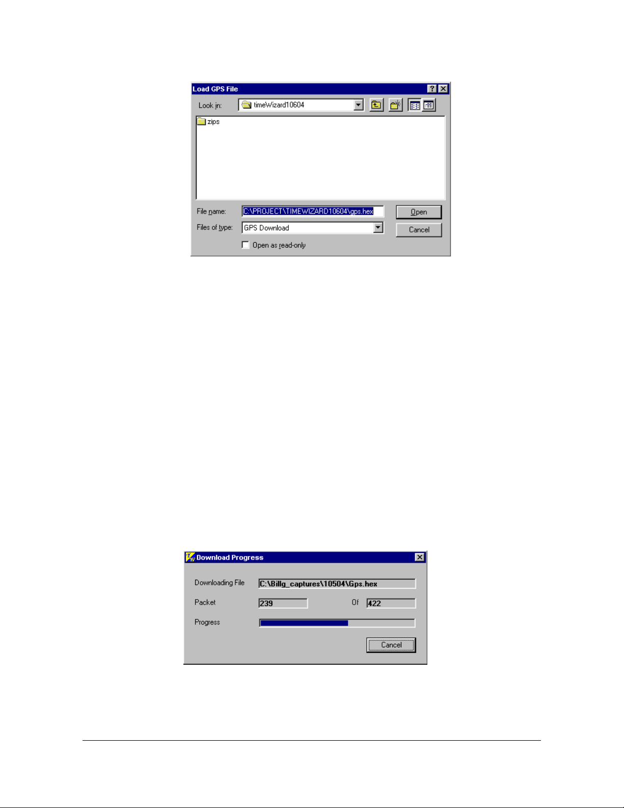
Chapter 3 Installing the TimeSource 3100
Installing TimeWizard
Figure 3-24. The Load GPS File Dialog Box
7. Navigate to the GPS.hex firmware file that you want to download, then click
Open. The message “Verifying version for C:\directory\Gps.hex
(approx 10 secs)” appears in the Command area of the screen. Once
TimeWizard has verified that the version of the firmware is correct, the t ext on the
ver Unknown button changes to show the version of the firmware to be
downloaded.
After TimeWizard verifies the firmware version, select the Download GPS.hex
check-box.
8. Click Next>> to start the firmware download operation. The Download Progress
dialog box appears, as shown in Figure 3-25.
As the download operation proceeds, the value in the Packet field increases, and
the Progress bar shows the progress of the operation. When the firmware
download is complete, the Download Progress dialog box closes.
After the Download Progress dialog box closes, continue with the next step.
Figure 3-25. The Download Progress Dialog Box
84 TimeSource 3100 User’s Guide 097-72020-01 Revision K – December 2005
Page 85

Chapter 3 Installing the TimeSource 3100
Notes:
1. You can abort the firmware download operation at any time by
clicking Cancel in the Download Progress dialog box.
2. If the download fails for any reason, a screen appears with
instructions to contact Symmetricom. If this happens, exit the
application, check the cable connections, and restart
TimeWizard.
Installing TimeWizard
After the Download Progress dialog box closes, continue to monitor the
messages reported in the Commands area of the screen.
After the firmware file finishes downloading from the PC to the TimeSource,
TimeSource requires more time to complete the firmware upgrade process.
During this time, it should not be interrupted. When the firmware upgrade is fully
complete, TimeWizard automatically advances to the next screen.
Downloading the TS3000.hex firmware
9. Click ver Unk nown in the Download TS3000.hex screen (this screen is similar in
appearance to the Download GPS.hex screen shown in Figure 3-23). The Load
TS3000 File dialog box appears (this screen is similar to Figure 3-24). If you do
not want to download the TS3000.hex file, click Next>> to skip to the next screen
and skip to Step 12.
10.Navigate to the TS3000.hex firmware file that you want to download, then click
Open. The message “Verifying version for C:\directory\
ts3000.hex (approx 10 secs)” appears in the Command area of the
screen. Once TimeWiza rd has verified that the versio n of the firmware is co rrect,
the text on the ver Unknown button changes to show the version of the firmware
to be downloaded.
After TimeWizard verifies the firmware version, select the Download TS3000.hex
check-box.
11.Click Next>> to start the firmware download operation. The Download Progress
dialog box appears, as shown in Figure 3-25.
As the download operation proceeds, the value in the Packet field increases, and
the Progress bar shows the progress of the operation. When the firmware
download is complete, the Download Progress dialog box closes.
Notes:
1. You can abort the firmware download operation at any time by
clicking Cancel in the Download Progress dialog box.
2. If the download fails for any reason, a screen appears with
instructions to contact Symmetricom. If this happens, exit the
application, check the cable connections, and restart
TimeWizard.
097-72020-01 Revision K – December 2005 TimeSource 3100 User’s Guide 85
Page 86

Chapter 3 Installing the TimeSource 3100
Installing TimeWizard
After the Download Progress dialog box closes, continue to monitor the
messages reported in the Commands area of the screen.
After the firmware file finishes downloading from the PC to the TimeSource, the
TimeSource requires more time to complete the firmware upgrade process.
During this time, it should not be interrupted. When the firmware upgrade is fully
complete, TimeWizard automatically advances to the next screen.
Note: After the TS3000.hex download operation successfully
completes, the TimeSource reboots so that it can use the newly
installed firmware. Upon rebooting, the system’s output might enter
the degraded region of the PRS mask for up to one hour.
Verifying the Firmware Version
12.After the firmware has downloaded successfully, the Status Information screen
appears, as shown in Figure 3-26.
Figure 3-26. The Status Information Screen
Verify that the GPS.hex Ver and TS3000.hex Ver fields indicate that the correct
versions of the GPS.hex and TS3000.hex firmware are now installed.
Setting Alarm Parameters
13.Click Next>> when the correct versions are installed. The Set the Alarm
Parameters screen appears, as shown in Figure 3-27.
86 TimeSource 3100 User’s Guide 097-72020-01 Revision K – December 2005
Page 87
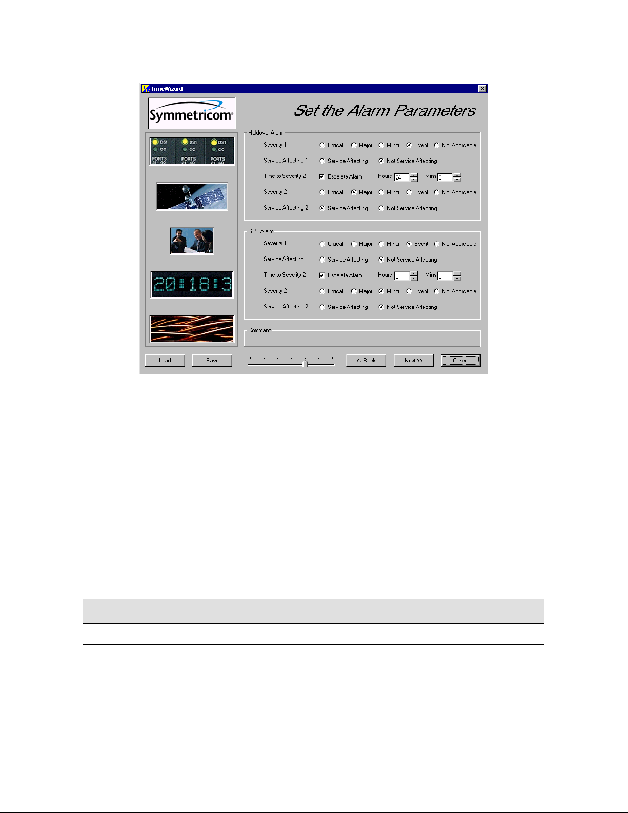
Chapter 3 Installing the TimeSource 3100
Installing TimeWizard
Figure 3-27. The Set the Alarm Parameters Screen
The Load and Save buttons allow a file to be generated that saves the alarm
parameters in a file called TS3Kconf.sym as default. The file name for a
configuration can be saved by selecting the Save button and providing a file
name. The Load button allows the user to load a saved file that will automatically
configure the Alarm Parameters screen.
This screen allows the parameters for GPS and Holdover alarm conditions to be
modified. If you do not want to modify any of the alarm paramete rs, click Next>>
and continue with Step 21. Otherwise, continue with the next step.
14.Choose the alarm parameters as desired. Table 3-8 describes each setting.
Table 3-8. Alarm Parameters
Setting Description
Severity 1 The initial severity of the alarm.
Service Affecting 1 The initial service affecting status of the alarm condition.
Time to Severity 2 If the Escalate Alarm check-box is selected, the alarm will be escalated
to the severity and service affecting status selected under Severity 2
and Service Affecting 2, after the time period selected und er Ho ur s an d
Mins has been reached. If the Escalate Alarm check-box is not
selected, the alarm will not be escalated.
097-72020-01 Revision K – December 2005 TimeSource 3100 User’s Guide 87
Page 88

Chapter 3 Installing the TimeSource 3100
Installing TimeWizard
Table 3-8. Alarm Parameters (Continued)
Setting Description
Severity 2 The severity of the alarm after it has been escalated.
Service Affecting 2 The service affecting status of the alarm condition after the alarm has
been escalated.
Set the alarm parameters as needed.
15.Click Next>>. The View the Alarm Parameters window appears, as shown in
Figure 3-28.
Figure 3-28. The View the Alarm Parameters Window
This screen confirms the alarm parameter settings from the previous screen. To
change any of the settings, click <<Back and repeat step 14.
16.Click Next>> when the alarm parameter settings are correct. The Exit
Application window appears, as shown in Figure 3-29.
88 TimeSource 3100 User’s Guide 097-72020-01 Revision K – December 2005
Page 89

Chapter 3 Installing the TimeSource 3100
Installing TimeWizard
Figure 3-29. The Exit Application Window
This screen allows you to save the log file from the download operation, or exit
TimeWizard without saving the log file.
If you do not wish to save the log file, ensure that the Save Log File to check-box
is not selected, then click Exit to complete the TimeWizard firmware installation
procedure. To save the log file, continue with the next step.
Saving the Log File
17.Select the Save Log File to check-box, then click the button that is adjacent to
the check-box to invoke the Save Log File dialog box, which appears as shown in
Figure 3-30.
097-72020-01 Revision K – December 2005 TimeSource 3100 User’s Guide 89
Page 90

Chapter 3 Installing the TimeSource 3100
Factory Default Values
Figure 3-30. The Save Log File Dialog Box
18.Navigate to the location to where the log file is to be stored, enter a name fo r the
log file into the File Name field, then click Save.
19.Click Exit to complete the TimeWizard firmware installation procedure.
Factory Default Values
The parameter values initially set at the factory are shown in Table 3-9
Table 3-9. Parameter Factory Settings
<aid> Parameter Setting
TS3100 FREQ=5MHz
TS3100 HOLDOVER
ALARM
TOD=NONE
ALMCOND=ALW
IPNE=0.0.0.0 IPSUBNET=255.255.255.255
IPGATE=0.0.0.0
IPEM1=0.0.0.0
IPEM1PORT=0
IPEM2=0.0.0.0
IPEM2PORT=0
IPINACT=0
DCDPASSTHRU=INH DCDUSERPORT=2
BYPASS=ALW (990-72020-04 systems only)
TIME=24-0
SEV1=EV
SEV2=MJ
SAFF1=NSA
SAFF2=SA
90 TimeSource 3100 User’s Guide 097-72020-01 Revision K – December 2005
Page 91

Table 3-9. Parameter Factory Settings (Continued)
<aid> Parameter Setting
TS3100 GPS ALARM TIME=3-0
SEV1=EV
SEV2=MN
SAFF1=NSA
SAFF2=NSA
GPS ANTCBLDLY=0
ANTELEVMASK=10
RO-A, RO-B ENSEMBLER=INH
MONITOR=INH
SPAN-A, SPAN-B ENSEMBLER=INH
MONITOR=INHSSM=INH
SSM=INH
SIGNAL=DIGITAL
SSMCHANNEL=4
Chapter 3 Installing the TimeSource 3100
Factory Default Values
SPAN-A, SPAN-B
LOS ALARM
SPAN-A, SPAN-B
AIS ALARM
SPAN-A, SPAN-B
LOS ALARM
SPAN-A, SPAN-B
ERROR ALARM
RO-A, RO-B LOS
ALARM
TIME=24-0
SEV1=EV
SEV2=MN
SAFF1=NSA
SAFF2=NSA
TIME=24-0
SEV1=EV
SEV2=MN
SAFF1=NSA
SAFF2=NSA
TIME=24-0
SEV1=EV
SEV2=MN
SAFF1=NSA
SAFF2=NSA
TIME=24-0
SEV1=EV
SEV2=MN
SAFF1=NSA
SAFF2=NSA
TIME=24-0
SEV1=EV
SEV2=MN
SAFF1=NSA
SAFF2=NSA
097-72020-01 Revision K – December 2005 TimeSource 3100 User’s Guide 91
Page 92

Chapter 3 Installing the TimeSource 3100
Factory Default Values
Table 3-9. Parameter Factory Settings (Continued)
<aid> Parameter Setting
RO-A, RO-B
ERROR ALARM
TIME=24-0
SEV1=EV
SEV2=MN
SAFF1=NSA
SAFF2=NSA
E1-A, E1-B FRAMING=CAS4
ALMOUT=AIS
COM-1,
COM-2,
COM-3
BAUD=9600
MONMSG=INH
KEEPALIVE=0
ENDOFTEXT=00
ECHO=ALW
COMPRI=ALW1
AUTOLOGOFF=20
HWCONTROL=INH
SWCONTROL=INH
PARITY=NONE
STOP=1
COM-5001,
COM-5002,
COM-5003,
COM-5004
MONMSG=INH
KEEPALIVE=0
ENDOWTEXT=00
ECHO=ALW
COMPRI=INH
AUTOLOGOFF=20
SWCONTROL=INH
COM-5551 MONMSG=INH
KEEPALIVE=0
ENDOFTEXT=00
ECHO=INH
COMPRI=INH
AUTOLOGOFF=20
SWCONTROL=INH
92 TimeSource 3100 User’s Guide 097-72020-01 Revision K – December 2005
Page 93

Chapter 4 TL1 Reference
This chapter provides information for using the TL1 language.
In This Chapter
Conventions
Command Format
Response Format
Parameters
Autonomous Messages
Tasks/Commands
Commands
097-72020-01 Revision K – December 2005 TimeSource User’s Guide 93
Page 94

Chapter 4 TL1 Reference
Conventions
Conventions
Uppercase letters in a command designate parameter values which must be
entered as shown. Lowercase letters in a command are the parameter name, and
the specific values that must be entered for the parameter. The Parameters section
of this chapter describes the parameters and the values where a value is the same
for all parameters. Parameter values for a particular command are listed with the
command. The system accepts either uppercase, lowercase, or a mixture of both,
but upper and lower case cannot be mixed within a parameter block.
The following symbols are used in the input and response messages:
[ ] encloses an optional parameter
{ } encloses a group of parameters, at least one of which must be entered
| separates alternatives in a group of parameters, at least one of which must
be entered
^ indicates a space (used in the description of the response format, but not
used in the command responses)
_ separates command code fields
: separates parameter blocks
, separates parameters within a block
; terminates a command, and causes execution
" " encloses text to be parsed by a machine
/* */ encloses comments for humans encloses a TL1 named variable
\" "\ encloses a description of a condition
... indicates the previous line in a response may be repeated as required
Command Format
A command consists of a command code of up to three fields separated by
hyphens, followed by parameter blocks separated by colons. Figure 4-1 shows the
command format. Parameter blocks consist of one or more parameters separated
by commas.
94 TimeSource User’s Guide 097-72020-01 Revision K – December 2005
Page 95
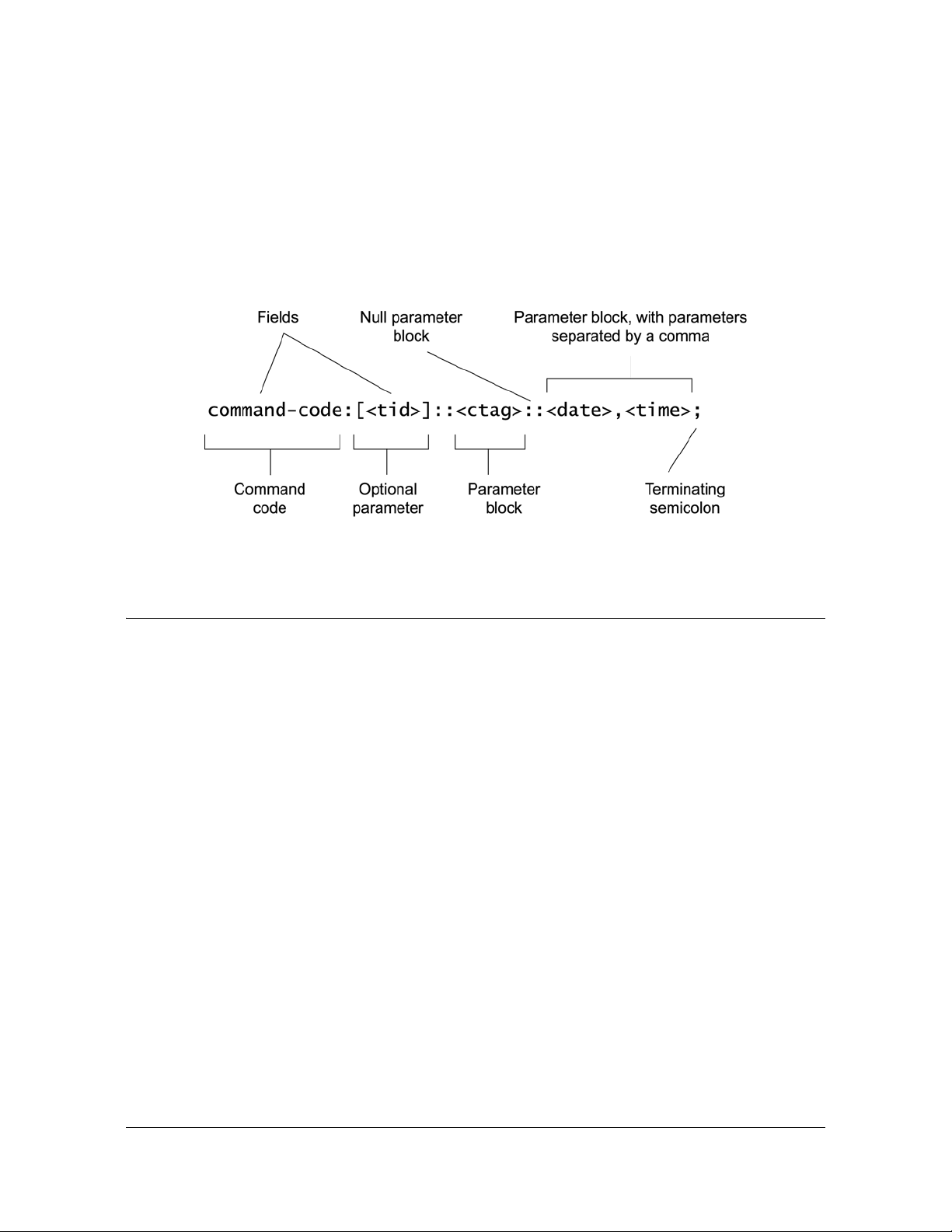
Chapter 4 TL1 Reference
^^^<sid>^<d
Response Format
Parameter blocks may be null (contain no parameters), or contain one or more
parameters. Two colons occur next to each other if a parameter block is null.
Multiple parameters in a parameter block are separated by commas. Two commas
occur next to each other if a parameter is null.
Entering a semicolon at the end of the command indicates that the command
statement is completed to the interpreter, and executes the command.
Figure 4-1. Command Format
Response Format
When a command is received and processed, a response is returned. All responses
include a source identifier (<sid>), the date, the time, an M to indicate that it is a
response to a command, and the correlation tag (<ctag>) that was entered with the
command.
Figure 4-2 shows the completed response format. COMPLD indicates that the
command completed without error.
ate>^<time>
M^^<ctag>^COMPLD
^^^/*LINK:,link>,CMD:<command>*/
;
Note: If the command was a query, additional information is displayed before the semicolon.
Figure 4-2. Completed Response Format
Figure 4-3 shows the denied response format. DENY indicates that the command
was denied due to an error. The <errcde> parameter indicates the corresponding
error type, or cause of the error.
097-72020-01 Revision K – December 2005 TimeSource User’s Guide 95
Page 96

Chapter 4 TL1 Reference
Parameters
^^^<sid>^<date>^<time>
M^^<ctag>^DENY
^^<errcode>
^^^/* <error message> */
^^^/*LINK:,link>,CMD:<command>*/
;
Figure 4-3. Deny Response Format
Parameters
The parameters that may be used in commands, responses, and messages are
defined in Table 4-1. When a parameter uses the same values in every instance,
those values are listed with the parameter in the table. When the context requires
different values for a parameter, the value is listed with the parameter in the
applicable commands, responses, and messages.
Table 4-1. Parameter Definitions
Parameter Definition
<aid> Access identifier for the object of the command or message. It may have
more than one part.
<almcde> Alarm code. Identifies the severity of the alarm based on its prio rity of action.
If multiple alarms are reported, almcde is the highest severity of those
reported.
<alt> Antenna location altitude in meters, specified to the thousandth of a meter,
referenced to mean sea level, in the forma t mm.mmm.
<atag> Automatic message tag. It is incremented by one for each autonomous
message. The <atag> value is a whole number from 001 throu gh 999, which
is reset to 001 at reset or when it rolls over.
<command> Echo of the entered command.
<conddescr> Text description of the condition. The <conddescr> value is limited to 64
characters starting and ending with a backslash and a double quot ation mark
(\"). Refer to the Troubleshooting chapter of this manual for the list of values.
<condeff> Effect on the condition of the equipment.
<condtype> Type of alarm condition.
<ctag> Correlation tag used to correlate input and response messages. The ctag
contains 1 to 6 characters. It must be included in a command, and the same
ctag is returned in the response.
96 TimeSource User’s Guide 097-72020-01 Revision K – December 2005
Page 97

Chapter 4 TL1 Reference
Table 4-1. Parameter Definitions (Continued)
<date> Current date in the 8-digit form: yyyy-mm-dd (command) or yyyy:mm:dd
(response or message), where yyyy is the year, mm is the month (01-12),
and dd is the day of the month (01-31). For example, May 3, 2000 is
2000-05-03.
<errcde> Four-character mnemonic error code, which is one of the following:
EFON = equipment feature option not provide d
ENEQ = not equipped
ICNV = command not valid
IDNV = invalid data in command
IDRG = invalid data range in command
IIAC = invalid aid in command
IICT = invalid correlation tag
IIDT = invalid data parameter in command
IISP = invalid syntax or punctuation
IITA = invalid tid
PIUI = invalid or duplicate uid or pid (privileged users only)
RALB = All units of requested type are busy
RCBY = circuit is busy
SCSN = invalid command sequence
SDBE = internal database error
SNIS = not in service
SNVS = not in a valid state
SRCN = requested condition currently exists
SRQN = request invalid
SWFA = working unit failed
Parameters
<error message> Error code text message
<link> Communication link identifier.
<modifier> Equipment initiating the alarm or event message, which is one of the
following:
TS3100 = system software
GPS = GPS receiver software
RO-x = remote oscillator input
SPAN-x = E1 span input
<ntfcncde> Notification code showing the alarm severity, which is one of the following:
CR = critical
MJ = major
MN = minor
<ocrdat> Occurrence date in the 8-digit form: yyyy-mm-dd (command) or yyyy:mm:dd
(response or message), where yyyy is the year, mm is the month (01-12),
and dd is the day of the month (01-31). For example, May 3, 2000 is
2000-05-03.
<ocrtm> Occurrence time in the 6-digit form: hh-mm-ss (command) or hh:mm:ss
(response or message), where hh is hours (00 to 23), mm is minutes (00 to
59), and ss is seconds (00 to 59). For example, 2:34 pm is14:34:00.
097-72020-01 Revision K – December 2005 TimeSource User’s Guide 97
Page 98

Chapter 4 TL1 Reference
Parameters
Table 4-1. Parameter Definitions (Continued)
<pid> Private identifier, factory-set to “TS3000!!”. It is the initial password for the
TELECOM <uid>. Passwords are encrypted when stored in the TimeSource
3100, and are never transmitted from the shelf. The pid contains a
case-insensitive string of 8 to 10 ASCII characters, and must include at least
one letter, one numeral, and one special character from the following:
! @ $ % * ( ) + ’ ? / ‘ <
<sid> Source identifier which is the name of the equipment sending the message.
The sid may be an identifier or text string, and may begin with a letter. A
maximum of 20 characters (limited to letters, digits, and hyphens) are
allowed. The sid is recommended to be the equipment's CLLI code.
<spec_block> Replaced by a number of parameters within the command. Param eters are in
the format <name>=<value>, may be entered in any order, and must be
separated by a comma.
<srveff> Identifies whether the alarm condition is service affecting:
SA = service affecting
NSA = not service affecting
<tid> Target identifier which identifies the equipment (TimeSource 3100) to which
the command is directed. The tid must be a valid TL1 iden tifier of a maximum
of 20 characters (limited to letters, digits, and hyphens) beginning with a
letter. The <tid> is recommended to be the target's CLLI code, but it can be
null if the OS directly interfaces to the target. The <tid> can be omitted only if
connection is made directly to a single TimeSource 3100 Shelf.
<time> Current time in the six-digit form: hh-mm-ss (command) or hh:mm:ss
(response or message), where hh is hours (00 to 23), mm is minutes (00 to
59), and ss is seconds (00 to 59). For example, 5:11:49 a.m. is 05:11:49.
<uap> User access level, used by a system administrator to assign a given level of
access to system users. User access level ranges from 1 to 5, with 1 being
the lowest access level, and 5 being the highest access level.
<uid> User identifier, factory-set to TELECOM. The <uid> contains alphanumeric,
case-insensitive strings of 6 to 10 characters provisioned as valid login IDs.
<uout> User inactivity password which indicates the number of days a system user
has not logged on to the system. The user inactivity time-out range is 0 to
180 days, with 0 indicating no time-out.
<vldty> Validity of the performance monitoring data.
98 TimeSource User’s Guide 097-72020-01 Revision K – December 2005
Page 99

Autonomous Messages
Autonomous messages are sent out when an alarm or event occurs. Two types of
autonomous messages are used:
Report Alarm: reports alarms
Report Event: reports events that are not alarms, or that have not yet become
alarms
Autonomous messages are listed on the following pages. After the messag e name,
a definition of the message is given.
Report Alarm
This autonomous message appears when an alarm is raised, and appears again
when the alarm is cleared.
Message:
Chapter 4 TL1 Reference
Autonomous Messages
^^^<sid> <date> <time>
M^^<almcde> <atag> REPT ALM EQPT <modifier>
^^^"<aid>:<ntfcncde>,<condtype>,<srveff>,
<ocrdat>,<ocrtm>,,,:\"<conddescr>\
"[:<dgntype>]"
Refer to Table 4-1 for parameter definitions.
Report Event
This autonomous message appears when an event is raised, and again when the
event is cleared; also appears when a transient event occurs. An event is a state of
the TimeSource 3100 that does not cause an alarm.
Message:
^^^<sid> <date> <time>
M^^<atag> REPT EVT EQPT <modifier>
^^^"<aid>:<condtype>,<condeff>,<ocrdat>,<ocrtm>
,,,,:\"<conddescr>\"[:<dgntype>]"
Refer to Table 4-1 for parameter definitions.
097-72020-01 Revision K – December 2005 TimeSource User’s Guide 99
Page 100

Chapter 4 TL1 Reference
Tasks/Commands
Tasks/Commands
To perform each task, use the command listed beside that task in Table 4-2.
Table 4-2. Commands for Tasks
Task Command Page
Log user onto system Activate User 102
Log user off of system Cancel User 103
Copy software program or database Copy Memory 104
Delete equipment from the database Delete Equipment 106
Delete a user from system Delete User Security 107
Change communication port parameters Edit Communication 108
Change the system date and time Edit Date 111
Change equipment parameters Edit Equipment 113
Enter equipment into the database and allow the
equipment to be used for monitoring
Enter a new user and configure the new user's user
name, password, and access level
Reset the alarm log Initialize Log 125
Reset to zero all performance monitoring
parameters associated with a given aid
Reset the system processor or GPS receiver
processor
Deactivate the audible office alarm Operate Alarm Cutoff All 128
Display current system alarms Retrieve Alarm All 129
Display current alarms for specific equipment Retrieve Alarm Equipment 130
Display current communication port parameter
settings
Display current system alarms and events Retrieve Condition All 134
Display current alarms and events for specific
equipment
Enter Equipment 122
Enter User Security 124
Initialize Register 126
Initialize System 127
Retrieve Communication 131
Retrieve Condition
Equipment
135
Display parameter settings of equipment Retrieve Equipment 136
Display GPS status information Retrieve GPS Status 143
Display header information Retrieve Header 144
100 TimeSource User’s Guide 097-72020-01 Revision K – December 2005
 Loading...