

Page 1

TimeSource 2700
CDMA Primary Reference Source
097-73000-02
Issue 1
Page 2

Symmetricom, Inc.
2300 Orchard Parkway
San Jose, CA 95131-1017
http://www.symmetricom.com
Copyright © 1999 Symmetricom, Inc.
All rights reserved. Printed in U.S.A.
All product names, service marks, trademarks and registered trademarks
used in this document are the proper ty of their respective owners.
2
TimeSource 2700
Page 3

Description
Chapter 1
Introduction........................ 14
PhysicalDescription ................. 15
FunctionalDescription............... 18
Overview........................ 18
Antenna......................... 20
CDMAReceiver.................. 20
LocalOscillator................... 20
ClockExtractors.................. 20
Ensemble Timing Generator. . . . . . . . 21
T1Output....................... 21
10MHzOutput ................. 21
BTMONitorSoftware............. 22
AlarmInterface................... 22
Power........................... 22
Engineering &
Ordering
Chapter 2
ShelfConsiderations................. 24
RackMounted.................... 24
WallMounted.................... 24
Computer Requirements . . . . . . . . . . . . 25
Systems ........................... 26
Optional Wire-Wrap Panel . . . . . . . . 26
Contents
3
Page 4

Installation
Chapter 3
Unpacking ......................... 30
AntennaInstallation.................. 31
Magnetic-MountAntenna.......... 31
High-GainAntenna ............... 32
ShelfInstallation..................... 35
RackMounting................... 35
WallMounting ................... 39
Cabling.......................... 39
PowerandFrameGround....... 41
OutputSpan(A,B) ............ 45
Craft......................... 47
RemoteRS-232................ 48
Alarms ....................... 49
Input Span (A, B) . . . . . . . . . . . . . . 50
10MHzOutput ............... 52
CDMAAntenna............... 52
Power-Up.......................... 53
Remote Operation via a Modem
(Optional)....................... 61
Remote Operation via a Terminal
Server(Optional)................. 66
4
TimeSource 2700
Page 5

Operation
Chapter 4
Introduction........................ 72
View Alarms and Alarm Thresholds . . . . 73
Change Alarm Thresholds . . . . . . . . . . . 75
View Output Framing and Output
DuringAlarms ................... 77
View BT3 (TimeSource 2700) Mode
andDuration .................... 78
ViewAlarmLog .................... 79
SetLocationID..................... 80
Enable Inputs . . . . . . . . . . . . . . . . . . . . . . . 81
Ensemble Inputs .................... 82
View Input Weighting and Gear . . . . . . . 83
View Input Performance Statistics . . . . . 84
Set Output Format and Output During
Alarm........................... 86
View CDMA Tracking Statistics . . . . . . . 88
View CDMA Pilot Information . . . . . . . . 89
Select Pilot Signal Channel . . . . . . . . . . . 92
Contents
5
Page 6

Operation
Chapter 4
(cont’d)
View Daily Holdover Information . . . . . 93
View Monthly Holdover Information . . . 95
Reset CDMA Receiver and System . . . . 97
DownloadNewSoftware ............ 98
ViewUserAccounts ................ 100
AddUserAccount.................. 101
DeleteUserAccount ............... 104
EditUserAccount .................. 105
ChangePassword ................... 107
View BTMONitor Software Version . . . 108
View Communication Information . . . . . 109
View System Firmware Information . . . 110
6
TimeSource 2700
Page 7

Troubleshooting
Chapter 5
FrontPanelLamps................... 112
Theory of Alarm Processing and
Troubleshooting.................. 114
CDMA Event and Alarm Summary . . 120
CDMA Frequency Transient Event 121
CDMA Frequency Event . . . . . . . . 121
CDMA Frequency Alarm . . . . . . . 121
CDMA Time Accuracy Transient
Event ..................... 122
CDMA Clock Bias Transient Event 122
CDMA Tracking Success Alarm . . 122
Span Input Event and Alarm
Summary ..................... 123
Span Frequency Transient Event . 123
Span Frequency Alarm . . . . . . . . . 124
Span Drift Transient Event . . . . . . 124
SpanDriftAlarm .............. 125
Span Phase Transient Event . . . . . 125
SpanPhaseAlarm ............. 126
SpanJitterAlarm .............. 126
Remote Oscillator (RO) Input
Event and Alarm Summary . . . . . . 127
RO Frequency Transient Event . . 127
RO Frequency Alarm . . . . . . . . . . 128
RO Drift Transient Event . . . . . . . 128
RODriftAlarm ............... 129
RO Phase Transient Event . . . . . . 129
ROPhaseAlarm .............. 130
ROJitterAlarm ............... 130
Contents
7
Page 8

Troubleshooting
Chapter 5
(cont’d)
Phase Lock Loop (PLL) Event
andAlarmSummary ........... 131
PLLStepEvent ................ 131
PLLStepAlarm ............... 132
PLLRangeEvent .............. 132
PLLRangeAlarm .............. 133
PLLJitterAlarm ............... 133
Temperature (TP) Event and
AlarmSummary............... 134
TPStepEvent ................ 134
TPStepAlarm ................ 134
TPSlewEvent ................ 135
TPSlewAlarm ................ 135
TL1Messages....................... 136
Formats......................... 136
Alarms ....................... 136
Events........................ 136
Parameters ...................... 137
Message Troubleshooting . . . . . . . . . . 139
Returning Equipment . . . . . . . . . . . . . . . . 143
TechnicalAssistance ................. 145
Sales............................... 146
ManualUpdates..................... 147
8
TimeSource 2700
Page 9

Specifications
Chapter 6
Magnetic-Mount Antenna . . . . . . . . . . 150
High-GainAntenna ............... 150
Remote Communication Port . . . . . . 151
CraftCommunicationPort......... 151
T1 Inputs ........................ 152
5 MHz Inputs .................... 153
T1Outputs...................... 154
10MHzOutput.................. 155
Alarms.......................... 156
Indicators........................ 156
Power........................... 157
ShelfMechanical.................. 157
Wire-Wrap Panel Mechanical. . . . . . . 158
Environmental.................... 158
Contents
9
Page 10

Acronyms and Abbreviations
AIS alarm indication signal
BTMONitor BesTime Monitoring
CDMA code division multiple access
DS1 digital signal, level 1 (1.544 Mb/s)
ESD electrostatic discharge
ESF extended superframe
GPS Global Positioning System
LOS loss of signal
MDEV mean time deviation
MPU microprocessor
ppb parts per billion
ppm parts per million
PRS primary reference source
RO remote oscillator
RU rack unit (1.75 inches)
SSM synchronization status messaging
T1 digital transmission (1.544 Mb/s)
TDEV time deviation
TL1 Transaction Language 1
UTC Universal Coordinated Time
Contents
10
Page 11

FCC Regulatory Statement
Warning: This equipment generates, uses, and can radiate radio
frequency energy, and if not used in accordance with the instruction
manual, may cause interference to radio communications. It has
been tested and found to comply with the limits for a Class A
computingdevicepursuanttoSubpartBofPart15ofFCCrules,
which are designed to provide reasonable protection against such
interference when operated in a commercial environment. Operation
of this equipment in a residential area is likely to cause interference
in which case the user at his own expense will be required to take
whatever measures may be required to correct the interference.
11
TimeSource 2700
Page 12

12
TimeSource 2700
Page 13

Description
This chapter provides a physical and functional
description of the TimeSource 2700.
Chapter
1
Page 14

SSSSSSSSSSSS SSSS S SSSSS SSSSSSS S SSS
Introduction
The TimeSource 2700 is a Primary Reference Source (PRS) that
tracks and ensembles multiple CDMA pilot signals. The CDMA
pilot signals originate from C DMA base stations equipped with
GPS based timing sources traceable to UTC. A pilot channel is
transmitted continuously by each CDMA base station. Pilot
channels allow the handset to acquire timing, provide phase data
for demodulation, and provide a signal strength comparison
between base stations.
The TimeSource 2700 provides Stratum 1 outputs by using
advanced BesTime technology. By using inputs from one to eight
CDMA pilots and a rubidium local oscillator, the TimeSource 2700
meets Telecondia GR2830 network performance requirements. If
the CDMA signals are disrupted, the BesTime algorithm continues
to predict CDMA timing information, which enhances system
holdover performance.
Since CDMA is one of the most widely-used digital wireless
services in the United States, the TimeSource 2700 can be
installed in most metropolitan areas. Because the antenna is
located inside the building within a few feet of the shelf, the
antenna installation problems sometimes encountered with GPS
based systems are eliminated.
14
TimeSource 2700
Page 15

SSSSSSSSSSSS SSSS S SSSSS SSSSSSS S SSS
Physical Description
The TimeSource 2700 consists of a shelf, an antenna with a cable,
mounting hardware, and software.
The shelf can be mounted on a wall o r in an industry-standard
19 inch or 23 inch rack. In a rack, the shelf occupies two rack
units (RU). Except for the antenna connector, all connectors and
indicators are on the front of the shelf.
Two types of antennas are available: the magnetic-mount antenna
and the high-gain antenna.
The magnetic-mount antenna (Figure 1) consists of a receiving
element, a magnetic base, and 12 feet of coaxial cable with an
SMA connector. Because the antenna has a magnetic base, the
antenna can be located on any convenient metal structure, such
as an equipment rack or cable tray.
Warning:
magnetic-sensitive media (e.g., floppy or hard disks).
The high-gain antenna (Figure 2) consists of a high-gain antenna,
12 feet of LMR-240 cable with SMA and N connectors, and
hardware for mounting the antenna to a cable runway.
Keep the magnetic-mount antenna away from
1
2
3
Description
4
5
15
Page 16

SSSSSSSSSSSS SSSS S SSSSS SSSSSSS S SSS
Figure 1. Magnetic-Mount Antenna
Receiving
element
Magnetic
base
12 ft
cable
SMA connector
16
TimeSource 2700
Page 17

SSSSSSSSSSSS SSSS S SSSSS SSSSSSS S SSS
Figure 2. High-Gain Antenna
Antenna
1
2
3
N connector
Description
4
5
17
Page 18

SSSSSSSSSSSS SSSS S SSSSS SSSSSSS S SSS
Functional Description
Overview
Figure3showsthemainfunctionsoftheTimeSource2700.The
center of the TimeSource 2700 is the BesTime Ensemb le Timing
Generator. The Ensemble Timing Generator can receive multiple
timing references, analyze their phase and frequency
characteristics, and dynamically weight each input, to maximize
the stability and accuracy of the timing outputs.
In the TimeSource 2700 application, the CDMA input normally
receives full weight, and actively disciplines the timing outputs.
Because of the exceptional stability of the local rubidium
oscillator, the optional span line and 5 M Hz remote oscillator
inputs are not normally used in the ensembled timing output
solution. If any of the optional inputs are provisioned for
ensembling, the BesTime algorithm continuously determines the
optimum input weighting mix, and may use one or all of these
references, by dynamically placing increasingly greater weighting
values on the most stable input or inputs. G reater weighting
values are not normally placed on the optional inputs, but if this
is the case, it would occur during extended CDMA outage periods.
18
Even if the optional inputs are not actively used in the output
ensemble, the BesTime Ensemble Timing Generator continuously
collects full timing statistics on each input, with respect to the
output timing signal. These statistics can be used to detect timing
problems on an incoming reference.
TimeSource 2700
Page 19

SSSSSSSSSSSS SSSS S SSSSS SSSSSSS S SSS
Figure 3. TimeSource 2700 Block Diagram
Optional
sources
RO input A
Antenna
input
T1 input
span A
T1 input
span B
CDMA
Receiver
Local Rb
Oscillator
Clock
Extractor
Clock
Extractor
Clock
Extractor
Alarm
Interface
MPU
Ensemble
Timing
Generator
TL1 messages
Alarm contacts
Status lamps
Local computer
with BTMONitor
Remote computer
with BTMONitor
Output span A
Output span B
10 MHz
1
2
3
RO input B
–48 V in
–48 V in
Clock
Extractor
Power
Supply
Power to shelf
Power to shelf
Description
4
5
19
Page 20

SSSSSSSSSSSS SSSS S SSSSS SSSSSSS S SSS
Antenna
The CDMA antenna mounts inside the building within 12 feet of
the TimeSource 2700 Shelf. A single cable transports the CDMA
pilot signals to the she lf.
CDMA Receiver
The CDMA Receiver automatically and continuously tracks
multiple 1930 MHz-to-1990 MHz PCS band CDMA pilot signals.
Local Oscillator
A rubidium oscillator, based on a digitally controlled servo-loop,
provides an ultra-stable local oscillator signal, which is sent to the
Ensemble Timing Generator.
Clock Extractors
20
T1 signals (bridged or terminated) and remote oscillator signals
can enter on the Input Span A and B connectors. These optional
inputs can be monitored, or used as back-up inputs to the system,
in case of a long-term loss of the CDMA input. A Clock Extractor
circuit extracts a clock from each of these signals, and sends the
clocks to the Ensemble Timing Generator.
TimeSource 2700
Page 21

SSSSSSSSSSSS SSSS S SSSSS SSSSSSS S SSS
Ensemble Timing Generator
The clock signals from the CDMA Receiver, a local oscillator, T1
span lines (optional), and 5 MHz remote oscillators (optional) are
used as sources by the BesTime algorithms in the Ensemble
Timing Generator. The signals are analyzed for MDEV, TDEV, and
other phase and frequency characteristics.
The BesTime Ensemble Timing Generator uses statistical clock
models to analyze each clock, and to synthesize highly stable
output timing signals.
T1 Output
The Ensemble Timing Generator provides the timing for the T1
timing signals available at the Output Span A and B connectors in
a framed, all-ones format, which is selectable in either D4 or ESF
framing. SSM is available with ESF framing.
10 MHz Output
The Ensemble Timing Generator provides the timing for the
10 MHz low-phase-noise timing signal, available at the 10 MHz
Output connector, which can be used for local cellular frequency
or testing purposes.
1
2
3
4
Description
5
21
Page 22

SSSSSSSSSSSS SSSS S SSSSS SSSSSSS S SSS
BTMONitor Software
BTMONitor (BesTime Monitoring) is a Windows 95/98/NT
compatible craft software program, which provides system
configuration, alarms, and diagnostics. BTMONitor resides on a
user-provided PC, and interfaces to the Tim eSourc e 2700 Shelf via
the local (Craft) or remote (Remote) RS-232 communication port.
Alarm Interface
The MPU delivers major and minor alarms to dry-contact type
connections at the Alarms connector. Alarms are also indicated by
the front-panel status lamps, by the BTMONitor application,
which provides extensive reports of alarm status, and by TL1
messages reported via the Craft COM port.
Power
A power converter filters and converts–48 volt dc power supplied
to the shelf into the voltages required by the shelf. Dual power
feeds are supplied through the Power A and B connectors.
22
TimeSource 2700
Page 23

Engineering & Ordering
This chapter describes mounting configurations for the
TimeSource 2700 Shelf, lists computer requirements for
operating the TimeSource 2700, and lists parts included
in the TimeSource 2700 System.
Chapter
2
Page 24

SSSSSSSSSSSS SSSS SSSS SSSSSSS S SSS
Shelf Considerations
Rack Mounted
The TimeSource 2700 Shelf can be mounted in either a
19 inch or 23 inch rack. Supplied mounting ears can be
positioned for flush or 5 inch offset mounting. Allow for two
RUs (3-1/2 inches) of vertical space on the rack, per shelf.
To make power, input, output, and alarm connections from
the rear of the rack, instead of the front of the shelf, a
wire-wrap panel is available separately, as an option. The
wire-wrap panel can be mounted below a rack-mounted
shelf, in either a 19 inch or 23 inch rack. Mounting ears
(supplied with the option) can be positioned for flush or
5 inch offset mounting. Allow for two RUs (3-1/2 inches) of
vertical space on the rack, per wire-wrap panel.
Wall Mounted
24
The TimeSource 2700 can be attached to a wall or other
surface by ordering the appropriate wall-mount
configuration option.
TimeSource 2700
Page 25

SSSSSSSSSSS SSSS SSSS SSSSSSS S SSS
Computer Requirements
A user-supplied computer is required to operate the
TimeSource 2700 System. Minimum requirements are as
follows:
• Operating system: Windows 95, Windows 98, or Windows NT 4.0
• CPU: x486 or equivalent, at 33 MHz
•RAM:8MB
• Serial communications port
• 3-1/2 in. floppy disk drive
• Recommended: spreadsheet application that can accept
comma-delimited (.csv) data files, to process the logged
files
2
2
3
Engineering & Ordering
4
5
25
Page 26

SSSSSSSSSSSS SSSS SSSS SSSSSSS S SSS
Systems
Table A lists the parts included in TimeSource 2700
Systems. There are four kits for TimeSource 2700 Systems:
• Rack-mount shelf with magnetic-mount antenna
• Wall-mount shelf with magnetic-mount antenna
• Rack-mount shelf with high-gain antenna
• Wall-mount shelf with high-gain antenna
Optional Wire-Wrap Panel
The wire-wrap panel (990-73000-11) is available separately,
as an option, for the rack-mounted TimeSource 2700. It
includes the panel and cables for connecting to the
TimeSource 2700, and hardware for mounting in a 19 inch
or 23 inch rack.
26
TimeSource 2700
Page 27

SSSSSSSSSSS SSSS SSSS SSSSSSS S SSS
Table A. TimeSource 2700 Parts
Part Number Description
Rack-Mount Shelf with Magnetic-Mount Antenna (990-73000-02)
090-73000-02 TimeSource 2700 Shelf
093-73010-01 Magnetic-mount antenna with 12 ft cable
093-73000-02 Hardware kit (mounting brackets [2 RU] and hardware for mounting in a
19 in. or 23 in. rack)
992-73000-01 BTMONitor software
997-73000-02 Manual
060-00067-01 Cable for connecting to a PC
Wall-Mount Shelf with Magnetic-Mount Antenna (990-73000-03)
2
2
090-73000-02 TimeSource 2700 Shelf
093-73010-01 Magnetic-mount antenna with 12 ft cable
093-71000-03 Hardware kit (2 angle brackets and bracket mounting screws [user must
supply screws for mounting shelf to a wall])
992-73000-01 BTMONitor software
997-73000-02 Manual
060-00067-01 Cable for connecting to a PC
Engineering & Ordering
3
4
5
27
Page 28

SSSSSSSSSSSS SSSS SSSS SSSSSSS S SSS
Table A. TimeSource 2700 Parts (cont’d)
Part Number Description
Rack-Mount Shelf with High-Gain Antenna (990-73000-04)
090-73000-02 TimeSource 2700 Shelf
093-73010-02 High-gain antenna kit (includes 12 ft cable and mounting hardware)
093-73000-02 Hardware kit (mounting brackets [2 RU] and hardware for mounting in a
19 in. or 23 in. rack)
992-73000-01 BTMONitor software
997-73000-02 Manual
060-00067-01 Cable for connecting to a PC
Wall-Mount Shelf with High-Gain Antenna (990-73000-05)
090-73000-02 TimeSource 2700 Shelf
093-73010-02 High-gain antenna kit (includes 12 ft cable and mounting hardware)
093-71000-03 Hardware kit (2 angle brackets and bracket mounting screws [user must
supply screws for mounting shelf to a wall])
992-73000-01 BTMONitor software
997-73000-02 Manual
060-00067-01 Cable for connecting to a PC
28
TimeSource 2700
Page 29

Installation
This chapter provides the steps required to
install and power-up the TimeSource 2700.
Chapter
3
Page 30

SSSSSSSSSSSS SSSS S SSSSS SSSSSSS S SSS
Unpacking
Install the TimeSource 2700, using steps in the order given in this
chapter. If any difficulties are encountered during the installation
process, contact Symmetricom’s Customer Technical Assistance
Center (CTAC) at:
• 1 888 367 7966 (North America and other areas, where available)
• +1 408 428 7907 (U.S.A.)
• +44 1483 510300 (U.K.)
CTAC includes Product Technical Support for technical
information, and Customer Service for information about an order,
RMAs, and other information.
30
Warning:
procedures regarding electrostatic discharge (ESD), including:
Note:
packed in the original packing material. Contact CTAC if additional
packaging is needed.
Unpack equipment carefully; check for completeness against the
purchase order. Notify Symmetricom if items are missing.
Inspect equipment for shipping damage, including bent or loose
hardware, and broken connectors.
If equipment was damaged in transit, contact Customer Service to
request an RMA, and notify the carrier.
TimeSource 2700
When handling electronic equipment, use local office
• Use grounded wrist straps connected to equipment frame
ground when handling cards.
• Store cards only in antistatic packaging provided by the factory.
Save packing material. All equipment returned must be
Page 31

SSSSSSSSSSSS SSSS S SSSSS SSSSSSS S SSS
Antenna Installation
Installation procedures are to follow local company procedures
andtheInstallationJobSpecification.
The antenna can be located anywhere a CDMA signa l can be
received. Locate the antenna high enough so that:
• Traffic (people o r equipment) moving in the vicinity cannot
touch the antenna and dislodge it.
• Traffic (people o r equipment) moving in the vicinity cannot
interfere with the CDMA signal.
Magnetic-Mount Antenna
For TimeSource 2700 Systems with magnetic-mount antennas,
use this section, and skip the “High-Gain Antenna” section.
For TimeSource 2700 Systems with high-gain antennas, skip this
section, and use the “High-Gain Antenna” section.
3
3
Installation
4
5
31
Page 32

SSSSSSSSSSSS SSSS S SSSSS SSSSSSS S SSS
The antenna has a magnetic base, therefore no installation
hardware is required. Magnetically attach the antenna to any
metallic structure, such as an equipment rack or overhead cable
tray. The antenna can be in any orientation (pointing up, down, or
horizontally).
Warning:
media (e.g., floppy or hard disks).
RoutetheantennacabletotherearofwheretheTimeSource2700
Shelf will be located, and out of the way of traffic. Use tie-wraps or
equivalent to dress the cable in accordance with office procedures.
Note:
procedure. Duringthat procedure, the strength of the CDMA signal
will be measured. Based on that measurement, the location of the
antenna may have to be changed to improve the signal strength.
Keep the antenna away from magnetic-sensitive
At the end of this Installation chapter, there is a power-up
High-Gain Antenna
For TimeSource 2700 Systems with high-gain antennas, follow
ProcedureA,andrefertoFigure4.
Note:
way, which is the recommended procedure. Follow local company
procedures and the Installation Job Specification to mount the
antenna.
For TimeSource 2700 Systems with magnetic-mount antennas,
use the “Magnetic-Mount Antenna” section.
Procedure A describes mounting the antenna to a cable run-
32
TimeSource 2700
Page 33

SSSSSSSSSSSS SSSS S SSSSS SSSSSSS S SSS
Procedure A. High-Gain Antenna Mounting
Step Action
1 Assemble the antenna and mounting bracket as follows:
a. Slide the N connector end of the antenna through the double D shaped hole in the bracket.
b. Slide the washer over the N connector, and position against the bracket.
c. Screw the nut over the N connector, onto the assembly.
2 Position the antenna bracket assembly against the front of the cable runway, with the
double D shaped hole pointing away from the cable runway.
3 From the rear of the runway, position the clamp around the runway, and slide the clamp through
the bracket slot and top hole.
4 Slide the two washers on the clamp, and position against the bracket.
5 Screw the two nuts on the clamp, and attach.
6 Attach the N end of the antenna cable to the antenna.
7 Route the antenna cable to the rear of where the TimeSource 2700 Shelf will be located,
and out of the way of traffic. Use tie-wraps or equivalent to dress the cable in accordance
with office procedures.
Note:
During that procedure, the strength of the CDMA signal will be
measured. Based on that measurement, the location of the
antenna may have to be changed to improve the signal strength.
At the end of this chapter, there is a power-up procedure.
Installation
33
3
3
4
5
Page 34

SSSSSSSSSSSS SSSS S SSSSS SSSSSSS S SSS
Figure 4. High-Gain Antenna Mounting
Mounting bracket
Antenna
Washer and nut
Cable runway
Clamp
Washer and nut
Washer and nut
N connector
Antenna cable
34
TimeSource 2700
Page 35

SSSSSSSSSSSS SSSS S SSSSS SSSSSSS S SSS
Shelf Installation
Rack Mounting
The mounting ears, as shown in Figure 5, can be positioned for
flush or 5 inch offset mounting, in either a 19 inch rack
(Figure 5A) or a 23 inch rack (Figure 5B). To mount the shelf,
follow Procedure B.
Figure 5. Rack Mounting Options
Rear of rack
Top of shelf
A. Rack mounting – 19 in. rack
5in.offset
Flush
mount
Rear of rack
Top of shelf
B. Rack mounting – 23 in. rack
23 in. rack adapters
3
3
4
5
Installation
35
Page 36

SSSSSSSSSSSS SSSS S SSSSS SSSSSSS S SSS
Procedure B. Rack Mounting
Step Action
1 Position the mounting ears on the shelf for flush mounting or 5 in. offset mounting, as
required. If mounting in a 23 in. rack, attach the 23 in. rack adapters.
2 Mount the shelf in the rack.
3 If a wire-wrap panel is not used, this procedure is completed. If using a wire-wrap panel,
mount the panel (Figur e6) to the rack just below the TimeSourc e2700.
4 Connect the cables (included in the wire-wrap panel kit) between the front panel
connectors of the TimeSource 2700 and the connectors on the inside of the wire-wrap
panel, as listed in Table B.
36
TimeSource 2700
Page 37

SSSSSSSSSSSS SSSS S SSSSS SSSSSSS S SSS
Figure 6. Rack Mounting with Wire-Wrap Panel
Shelf front panel
Cables from front
of shelf to
wire-wrap panel
Rack
A. Side view
TimeSource 2700
Wire-wrap
pins
Wire-wrap panel
TimeSource 2700
3
3
B. Front view
Wire-wrap panel
Installation
4
5
37
Page 38

SSSSSSSSSSSS SSSS S SSSSS SSSSSSS S SSS
Ta b l e B . C a b l e C o n n e c t i o n s
TimeSource 2700 Wire-Wrap Panel Cable Type
Power A P1 PWR-A DB9 – 3-pin Molex
Power B P2 PWR-B DB9 – 3-pin Molex
OutputSpanA J3OUTPUTA RJ-45–5-pinMolex
OutputSpanB J4OUTPUTB RJ-45–5-pinMolex
Alarms J5 ALARM RJ-45 – 5-pin Molex
Input Span A J1 INPUT A RJ-45 – 5-pin Molex
Input Span B J2 INPUT B RJ-45 – 5-pin Molex
38
TimeSource 2700
Page 39

SSSSSSSSSSSS SSSS S SSSSS SSSSSSS S SSS
Wall Mounting
The TimeSource 2700 can be attached to a wall or other surface.
Attach the proper mounting ears, included with the
TimeSource 2700, as shown in Figure 7, then use appropriate
screws (not included) to attach to the chosen surface.
Figure 7. Wall Mounting
Rear
Top
A. Top view
Cabling
The CDMA antenna connection is on the rear of the shelf. All other
connections are made on the front of the shelf. When installing the
TimeSource 2700 in a rack with a wire-wrap panel, connections
are made at the rear of the wire-wrap panel. Figure 8 shows the
locations of the connectors on the front of the shelf, and Figure 9
shows the locations of the connectors on the rear of the wire-wrap
panel.
Top
Front
B. Front view
3
3
4
5
Installation
39
Page 40

SSSSSSSSSSSS SSSS S SSSSS SSSSSSS S SSS
Figure 8. Shelf Front Panel Connectors
Power A,
Power B
Craft
RS-232
Not used
Output
span A, span B
Alarms
Input
span A, span B
Figure 9. Optional Wire-Wrap Panel Rear Panel Connectors
Power A
5MHzinput
Input
span A, span B
Alarms
10 MHz
output
Power B
Output
span A, span B
40
TimeSource 2700
Page 41

SSSSSSSSSSSS SSSS S SSSSS SSSSSSS S SSS
Power and Fr ame Ground
Caution:
power the TimeSource 2700 Shelf are removed before connecting
power.
Note:
replaceable fuses.
Shelf Front Panel
The–48 volt dc battery and frame ground enter through the
nine-pin male DB9 connectors labeled Power A and Power B.
Figure 8 shows the location of the connectors, and Table C lists
the connector pinouts.
Note:
available, connect the single office battery to the Power A connector
on the shelf front panel. This is not a recommended arrangement.
Solder the power and frame ground wires to a customer-supplied
female DB9 connector, following the pinouts listed in Table C, then
mate to the Power A or Power B connector on the front panel.
Note:
tery source, but do not apply the office battery to the TimeSource
2700 at this time.
Ensure the fuses in the fuse panel which will be used to
Input power is reverse polarity protected; there are no user
If two office battery supplies (battery A and battery B) are not
Connectthepowerleadsfrompins1and2totheofficebat-
3
3
4
Installation
5
41
Page 42

SSSSSSSSSSSS SSSS S SSSSS SSSSSSS S SSS
Table C. Front Panel Battery Connector Pinouts
Pin Signal
1 –48 V dc
2Batteryreturn
6 Frame ground
Note: Pins not listed are reserved
for future use.
Make the ground connection, following one of the methods
described below, depending on whether a ground rod is installed:
With ground rod:
Solder the frame ground connection to the 6 AWG frame ground
rod run vertically on each side of the rack. Use one of the
following methods for connecting the wire from pin 6 of the
DB9 connector to the 6 AWG rod.
42
TimeSource 2700
• Crimp an appropriate-size spade lug to the ground wire
from the DB9 connector, bend the lug around the 6 AWG
rod, and solder.
• Strip enough insulation fromthe ground wire from the DB9
connector to permit three complete turns around the
6AWGrod,andsolder.
Note:
When soldering, use a 25 watt soldering iron to ensure
the 6 AWG rod is heated suff iciently, to prevent a cold solder
connection.
Page 43

SSSSSSSSSSSS SSSS S SSSSS SSSSSSS S SSS
Without ground rod:
Crimp an appropriate-sized spade lug to the wire from pin 6 of
the DB9 connector, and secure the lug to a screw hole on the
rack. Remove the paint, and sand the area around the screw
hole, to ensure proper conductivity.
Wire-Wrap Rear Panel
The–48 volt dc battery and frame ground enter through the
PWR-A and PWR-B terminal blocks. Figure 9 shows the location of
the terminal blocks, and Table D lists the terminal block pins.
Note:
available, connect the single office battery to the PWR-A terminal
block on the rear of the wire-wrap panel. This is not a recommended arrangement.
Connect the power and frame ground wires to the terminals listed
in Table D, using appropriate sized spade lugs.
Note:
battery source, but do not apply the office battery to the TimeSource 2700 at this time.
Table D. Wire-Wrap Panel Battery Terminal Block Pinouts
If two office battery supplies (battery A and battery B) are not
Connect the leads from the – and + terminals to the office
Pin Signal
– –48 V dc
+Batteryreturn
F Frame ground
3
3
4
5
Installation
43
Page 44

SSSSSSSSSSSS SSSS S SSSSS SSSSSSS S SSS
Make the ground connection, following one of the methods
described below, depending on whether a ground rod is installed:
With ground rod:
Solder the frame ground connection to the 6 AWG frame ground
rod run vertically on each side of the rack. Use one of the
following methods for connecting the wire from terminal F of
the terminal block to the 6 AWG rod.
• Crimp an appropriate-size spade lug to the ground wire
from the terminal block, bend the lug around the 6 AWG
rod, and solder.
• Strip enough insulation from the ground wire from the
terminal block to permit three complete turns around the
6AWGrod,andsolder.
Note:
When soldering, use a 25 watt soldering iron to ensure
the 6 AWG rod is heated suff iciently, to prevent a cold solder
connection.
Without ground rod:
Crimpanappropriate-sizedspadelugtothewirefrom
terminal F of the terminal block, and secure the lug to a screw
hole on the rack. Remove the paint, and sand the area around
the screw hole, to ensure proper conductivity.
44
TimeSource 2700
Page 45

SSSSSSSSSSSS SSSS S SSSSS SSSSSSS S SSS
Output Span (A, B)
Shelf Front Panel
Connect the T1 outputs to the two RJ45 connectors labeled
Output Span A and Span B. Figure 8 shows the location of the
connectors on the front panel, and Table E lists the pinouts of
each connector (Output Span A and Span B).
Note:
Grounding the shield at both ends is not
Table E. Front Panel T1 Output Connector Pinouts
The s hield is normally grounded only at the signal source.
Pin Signal Name
4Ring
5Tip
7Frameground
8Frameground
Note: Pins not listed are reserved
for future use. Use category 5 EIA/
TIA 568 A or B compliant cable.
recommended.
3
3
4
Installation
5
45
Page 46

SSSSSSSSSSSS SSSS S SSSSS SSSSSSS S SSS
Wire-Wrap Rear Panel
Connect the T1 outputs to the two wire-wrap connectors labeled
OUTPUT DS1-A and DS1-B. Table F shows the location of the
connectors on the wire-wrap panel, and Table F lists the pins of
each connector (OUTPUT DS1-A and DS1-B).
Table F. Wire-Wrap Panel T1 Output Connector Pinouts
Pin Signal Name
RRing
TTip
SFrameground
46
TimeSource 2700
Page 47

SSSSSSSSSSSS SSSS S SSSSS SSSSSSS S SSS
Craft
Two communication ports are available. Both perform the same
function and are electrically the same. However, each port has a
different connector type.
Note:
Make a direct connection to the TimeSource 2700 communication
port at the RJ45 connector labeled Craft. Figure 8 shows the
location of the connector on the shelf front panel, and Table G lists
the pinouts of the connector.
Table G. Craft Terminal Connector Pinouts
Pin Signal Abbreviation Direction
2 Transmit data TXD From TimeSource 2700
3 Receive data RXD To TimeSource 2700
4 Data set ready DSR To TimeSource 2700
5 Signal ground GND —
6 Data terminal ready DTR From TimeSource 2700
7Frame — —
8Frame — —
TL1 messages are available only via the Craft port.
Note: Pins not listed are reserved for future use.
3
3
4
Installation
5
47
Page 48

SSSSSSSSSSSS SSSS S SSSSS SSSSSSS S SSS
Remote RS-232
Make connections to the d ata terminal equipment (DTE) port at
the 9-pin female DB9 connector labeled Remote RS-232. Figure 8
shows the location of the connector on the shelf front panel, and
Table H lists the pinouts of the connector.
Table H. Remote RS-232 Connector Pinouts
Pin Signal Abbreviation Direction
1 Data carrier detect DCD To TimeSource 2700
2 Receive data RXD To TimeSource 2700
3 Transmit data TXD From TimeSource 2700
4 Data terminal ready DTR From TimeSource 2700
5 Return/signal ground RTN —
6 Data set ready DSR To TimeSource 2700
7 Request to send RTS From TimeSource 2700
48
8 Clear to send CTS To TimeSource 2700
Note: Pins not listed are reserved for future use.
TimeSource 2700
Page 49

SSSSSSSSSSSS SSSS S SSSSS SSSSSSS S SSS
Alarms
Shelf Front Panel
The RJ45 connector labeled Alarms provides dry-contact relay
closure points. The relay contacts are normally open, and close
when reporting an alarm. Figure 8 shows the location of the
connector on the front panel. Connect between the Major pins for
a major alarm, and between the Minor pins for a minor alarm. The
pinouts of the connector are listed in Table I.
Table I. Alarms Connector Pinouts
Contacts
During
Pin Alarm
1 Major Open Closed Closed
5
2 Minor Open Closed Open
4
Note: Pins not listed are reserved for future use.
No Alarm
Contacts
During Alarm
Contacts
During
Power Off
Wire-Wrap Rear Panel
The two wire-wrap connectors labeled ALARM MAJ and MIN
provide dry-contact relay closure points. The relay contacts are
normally open, and close when reporting an alarm. Figure 9
shows the location of the connectors on the wire-wrap rear panel.
Connect between the MAJ connector + and – pins for a major
alarm, and between the MIN connector + and – pins for a minor
alarm.
3
3
4
5
Installation
49
Page 50

SSSSSSSSSSSS SSSS S SSSSS SSSSSSS S SSS
Input Span (A, B)
Shelf Front Panel
Connect the optional T1 inputs and the optional 5 MHz inputs to
the two RJ45 connectors labeled Input Span A and Span B.
Figure 8 shows the location of the connectors on the front panel,
and Table J lists the pinouts of each connector.
Note:
source. Grounding the shield at both ends is not
Table J. Front Panel T1 and 5 MHz Connector Pinouts
The T1 signal shield is normally grounded only at the signal
Pin Signal
1Ring
2Tip
3, 4 5 MHz (positive)
5, 6 5 MHz (negative)
7Frameground
8Frameground
Note: Pins not listed are reserved for
future use.
recommended.
50
TimeSource 2700
Page 51

SSSSSSSSSSSS SSSS S SSSSS SSSSSSS S SSS
Wire-Wrap Panel
Connect the optional T1 inputs t o the two wire-wrap connectors
labeled INPUT DS1-A and DS1-B. Figure 9 shows the location of
the connectors on the wire-wrap panel, and Table K lists the
pinouts of each connector.
Note:
source. Grounding the shield at both ends is not
Table K. Rear Wire-Wrap Panel DS1 Input Connector Pinouts
Connect the optional 5 MHz inputs to the two wire-wrap
connectors labeled INPUT 5M A and 5M B. Figure 9 shows the
location of the connectors on the wire-wrap panel, and Table L
lists the pins of the connectors.
Table L. Rear Wire-Wrap Panel 5 MHz Input Connector Pinouts
The T1 signal shield is normally grounded only at the signal
Pin Signal
RRing
TTip
SFrameground
Pin Signal
+5MHz(positive)
recommended.
3
3
4
–5MHz(negative)
Installation
5
51
Page 52

SSSSSSSSSSSS SSSS S SSSSS SSSSSSS S SSS
10 MHz Output
Connect a BNC connector from the connector labeled 10 MHz
Output to the equipment that will use the 10 MHz o utput signal.
Figure 8 shows the connector location on the shelf front panel.
CDMA Antenna
Connect the cable from the CDMA antenna to the SMA connector
labeled CDMA RF IN. Figure 10 shows the connector location on
the shelf rear panel.
Figure 10. Shelf Rear Panel Connector
CDMA
antenna
52
TimeSource 2700
Page 53

SSSSSSSSSSSS SSSS S SSSSS SSSSSSS S SSS
Power-Up
Use Procedure C to install BTMONitor at a site where the host
computer is connected to the Craft connector of the TimeSource
2700 with a cable, and set up BTMONitor.
Procedure C. Power-Up
Step Action
1 Locate a directory, or create a new directory, on your hard disk, to store the BTMONitor
application.
2 Copy the files from the BTMONitor disk to the directory.
3 Create a Windows shortcut to BTMONitor, and place the shortcut on the Windows
Desktop. One method to accomplish this is to open Windows Explorer in an unmaximized
window with some of the Desktop visible around it. Then, navigate to the BTMONitor file
and drag the file to the Desktop. Click OK if Windows asks to make a shortcut file.
4 Connect the supplied serial communications cable between the TimeSourc e2700 Craft
connector and a serial communications port on the computer.
3
3
5 Install fuses in the fuse panel that powers the TimeSource 2700. On the front panel, when
the Minor Alarm lamp is yellow, and the Locked lamp is blinking green, continue.
Installation
4
5
53
Page 54

SSSSSSSSSSSS SSSS S SSSSS SSSSSSS S SSS
Procedure C. Power-Up (cont’d)
Step Action
6 Open the BTMONitor application. The COMM Port Selection screen appears.
7 Choose a communications port by clicking one of the following:
• Select Last Used Port: COMx:. This selection will use the named serial communications
port, which BTMONitor identifies as the one used in the previous session, when the
OK button is clicked.
• Automatic Selection, Scan COM Ports. This selection will scan the serial
communications ports on the host computer for the communications port connected
to the TimeSource 2700, when the OK button is clicked.
• Manual Selection: Allows the user to enter or choose the host computer
communication port that is connected to the TimeSource 2700.
54
TimeSource 2700
Page 55

SSSSSSSSSSSS SSSS S SSSSS SSSSSSS S SSS
Procedure C. Power-Up (cont’d)
Step Action
8 Click OK. Verify a User Login screen appears (shown below).
3
3
Note:
Login screen, verify that the TimeSource 2700 is powered, and the serial communications
are connected. Then click OK, and repeat Steps 7 and 8.
If a dialog box appears stating, “Failed to Open COM Port” instead of the User
Installation
4
5
55
Page 56

SSSSSSSSSSSS SSSS S SSSSS SSSSSSS S SSS
Procedure C. Power-Up (cont’d)
Step Action
9 Enter the user name and password for this installation, then click the OK button. A screen
appears showing the version number, copyright date, and the serial port that
communicates with the TimeSource 2700 (shown below).
Notes:
1. The user name, “default1”, is set at the factory, and the password, “TS2700:”, is set at
the factory. Be sure to enter the entire password, including the colon.
2. Theusernameandpasswordarecase-sensitive.
3. If an incorrect user name and password are entered three consecutive times, the
BTMONitor application exits, and ends the attempted session. If this happens, re-open
the application, and enter the correct user name and password.
56
TimeSource 2700
Page 57

SSSSSSSSSSSS SSSS S SSSSS SSSSSSS S SSS
Procedure C. Power-Up (cont’d)
Step Action
10 Verify the correct version number and serial port, then click the OK button. The
BTMONitor main screen appears (shown below).
3
3
Installation
4
5
57
Page 58

SSSSSSSSSSSS SSSS S SSSSS SSSSSSS S SSS
Procedure C. Power-Up (cont’d)
Step Action
11 Select Configuration from the main screen, then select Installation, as shown below.
The Installation screen appears (shown below).
12 In the Location ID area: Enter two to eight alphanumeric characters for the
TimeSource 2700 identification. The identification name can be used to identify this
particular TimeSource 2700 among multiple TimeSource 2700 systems.
Caution:
Use the factory-set name, or enter a name. Do not leave this field blank.
13 Click the OK button to save the information on this screen to the TimeSourc e2700. A
dialog box appears to confirm the action (see below). Click Yes to save the parameters to
the TimeSource 2700.
58
TimeSource 2700
Page 59

SSSSSSSSSSSS SSSS S SSSSS SSSSSSS S SSS
Procedure C. Power-Up (cont’d)
Step Action
14 Select Performance Statistics from the main screen, then select CDMA Summary, as shown
below.
The CDMA Summary Report screen appears (shown below).
3
3
Installation
4
5
59
Page 60

SSSSSSSSSSSS SSSS S SSSSS SSSSSSS S SSS
Procedure C. Power-Up (cont’d)
Step Action
15 The system is factory-set to Auto Search for pilot channels on power up. Observe the
Lock display for each pilot. Any number other than 0 indicates the TimeSource 2700 has
detected, and locked onto, an acceptable pilot signal(s). Lock is required for only one pilot
for the system to produce PRS outputs. If Lock is not achieved within 30 min, move the
antenna to see if the system will detect an acceptable pilot signal.
Alternatively, do one of the following two options:
• Use a PCS CDMA phone with a signal strength indicator in the vicinity of the planned
shelf installation site. Choose the location in which to install the antenna by observing
the strongest signal strength on the phone. If the phone does not detect a signal, the
TimeSource 2700 should not be installed at that location.
• If the pilot signal channel for the PCS service provider is available, select the channel,
using the Select Pilot Signal Channel task in the Operation chapter. Selecting the correct
pilot signal channel allows the system to find and lock on the pilot signal(s) more quickly.
60
TimeSource 2700
Page 61

SSSSSSSSSSSS SSSS S SSSSS SSSSSSS S SSS
Remote Operation via a Modem (Optional)
Use Procedure D to set up communications between BTMONitor
and the TimeSource 2700 via a modem (Hayes compatible).
Procedure D. Installing BTMONitor Using a Modem
Step Action
1 Connect a straight-through serial communications cable (user supplied) between the
TimeSource 2700 Remote connector and serial communications port on the modem, and
verify all links between the modem and the host computer are connected.
2 From the BTMONitor main screen, click Exit.
3 Open the BTMONitor application. The COMM Port Selection screen appears.
3
3
Installation
4
5
61
Page 62

SSSSSSSSSSSS SSSS S SSSSS SSSSSSS S SSS
Procedure D. Installing BTMONitor Using a Modem (cont’d)
Step Action
4 On the Comm Port Selection screen, click the Use Profile option, on the left of the menu
bar. A standard Windows Open File screen appears (shown below), set to open a file
named profile.dat. If other profile files have already been created, they will appear in this
window.
Note:
The profile.dat file contains up to 10 communication profiles. A communication
profile contains modem settings, including a phone number, for communicating with a
TimeSource 2700 System. Instructions for creating a modem profile follow this paragraph.
The profile.dat file can be copied, and renamed, using standard Windows procedures (do
not change the dat file extension).
62
TimeSource 2700
Page 63

SSSSSSSSSSSS SSSS S SSSSS SSSSSSS S SSS
Procedure D. Installing BTMONitor Using a Modem (cont’d)
Step Action
5 Click the Open button. If the file has not yet been created, a dialog box appears (shown
below) that asks to create the file profile.dat. If the file has been created, the Comm.
Profile Edit screen appears (shown in Step 6).
6 Click the Yes button. The Comm. Profile Edit screen appears (shown below).
3
3
Installation
4
5
63
Page 64
SSSSSSSSSSSS SSSS S SSSSS SSSSSSS S SSS
Procedure D. Installing BTMONitor Using a Modem (cont’d)
Step Action
7 On the upper left side of the screen, highlight one of the 10 profiles in the Profile list box.
The highlighted selection appears in the TS Name box, below the Profile list box.
Note:
8 In the TS Name box, change the name of the modem profile, if desired. The TS name
should reflect the name of the TimeSource 2700 Shelf to which the profile connects.
9 Check that the Comm Port window displays the communication port that is connected to
the modem, and that the Modem button is selected.
10 On the right side of the screen, be sure the Baud Rate is 9600, the Parity is None, the
Number of Data Bits is 8, and the Number of Stop Bits is 1.
Caution:
11 Enter the phone number for the modem to dial in the Phone No. box.
12 Click the Save Profile button to save the changes made on this screen as the profile named
intheTSNamebox.AstandardWindowsOpenFilescreenappears(seeStep4).Afile
named profile.dat is set to be opened.
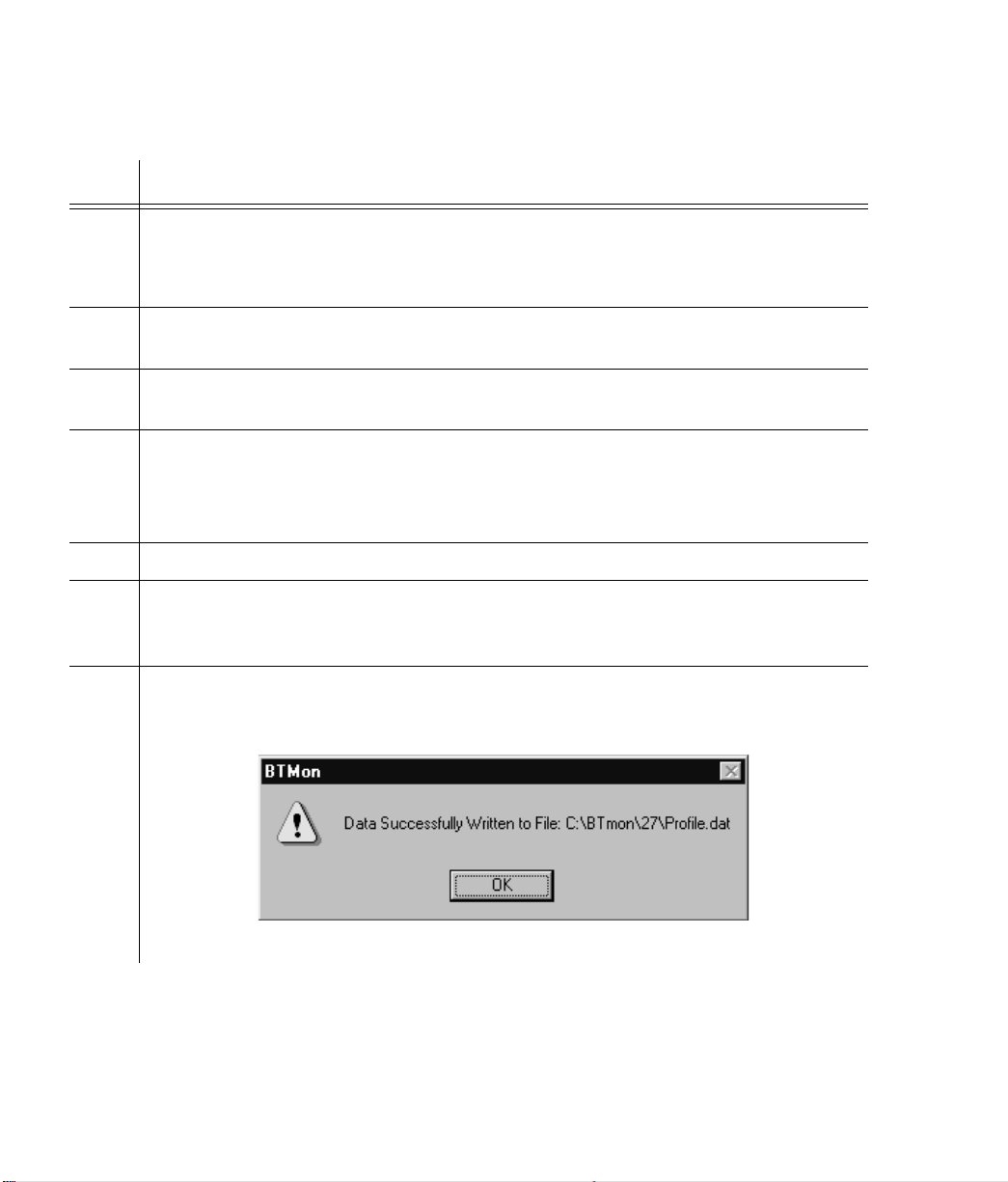
13 Click Open. BTMONitor opens the profile.dat file, enters data from the Comm. Profile
Edit screen, and closes the profile.dat file. A confirmation screen appears (shown below).
If an accurate profile exists, go to Step 16.
Factory settings are displayed on the Comm. Profile Edit screen, and must be used.
64
TimeSource 2700
Page 65

SSSSSSSSSSSS SSSS S SSSSS SSSSSSS S SSS
Procedure D. Installing BTMONitor Using a Modem (cont’d)
Step Action
14 Click OK. BTMONitor is now set up to communicate with the TimeSource 2700 via the
modem. The Comm. Profile Edit screen appears.
15 If desired, repeat Steps 7 through 14 to create another modem profile.
16 Highlight the appropriate profile, and click the Logon Using Profile button.
Note:
1 min, either the Successfully Connected or Timed Out (not connected) pop-up screen
appears. If the Timed Out pop-up screen appears, check that the modem configuration
procedure was correctly followed, then connect again.
Wait approximately 1 min for the connection to be made. After approximately
3
3
4
Installation
5
65
Page 66

SSSSSSSSSSSS SSSS S SSSSS SSSSSSS S SSS
Remote Operation via a Terminal Server (Optional)
Use Procedure E to set up communications between BTMONitor
and the TimeSource 2700 via a terminal server. This allows the
user to select and/or edit the terminal server number and the
terminal server port number, to allow the TimeSource 2700 to
communicate with the host computer via an LAN network. Consult
your system administrator and the manual supplied with your
terminal server to determine the server and port numbers.
Note:
TCP/IP address.
The following procedure requires a terminal server and a
66
TimeSource 2700
Page 67

SSSSSSSSSSSS SSSS S SSSSS SSSSSSS S SSS
Procedure E. Remote Operation via a Terminal Server
Step Action
1 From the BTMONitor main screen, click Exit.
2 Open the BTMONitor application. The COMM Port Selection screen appears.
3
3
3 Click Use TCP/IP.
4 Click the TCP/IP option, on the left of the menu bar.
5 Select or edit a terminal server and TCP/IP address by clicking one of the following:
• Select: Selects a terminal server and TCP/IP address
• Edit: Edits a terminal server and TCP/IP address.
If you click Select, continue to the next step. If you click Edit, skip to Step 7.
Installation
4
5
67
Page 68

SSSSSSSSSSSS SSSS S SSSSS SSSSSSS S SSS
Procedure E. Remote Operation via a Terminal Server (cont’d)
Step Action
6 In the Address/Port area of the Select IP Address screen (see below), highlight the desired
terminal server address and port, then click Use (the Use button will display the selected
address and port). Skip to Step 11.
68
TimeSource 2700
Page 69

SSSSSSSSSSSS SSSS S SSSSS SSSSSSS S SSS
Procedure E. Remote Operation via a Terminal Server (cont’d)
Step Action
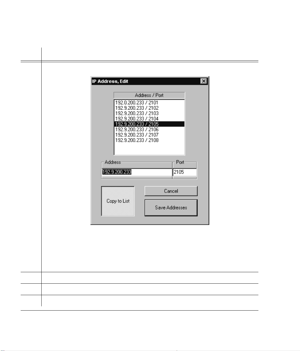
7 In the Address/Port area of the Edit IP Address screen (see below), highlight the terminal
server address and port to be edited, then click Edit Address (the Edit Address button will
change to Copy to List).
3
3
8 Type the address number, press the tab key, then type the port number.
Installation
4
5
69
Page 70
SSSSSSSSSSSS SSSS S SSSSS SSSSSSS S SSS
Procedure E. Remote Operation via a Terminal Server (cont’d)
Step Action
9 ClickCopytoList,thenclickSaveAddresses(seebelow).
Note:
To select the terminal server address and port just edited, perform the following:
a. Click the TCP/IP option, on the left of the Comm Port Select screen menu bar, then
click Select.
b. Highlight the desired terminal server address and port, then click Use.
10 Click OK.
11 Enter the user name and password for this installation, then click OK.
12 Verify the correct version number and serial port, then click OK.
70
TimeSource 2700
Page 71

Operation
This chapter provides tasks which may be required to
operate the TimeSource 2700.
Chapter
4
Page 72

SSSSSSSSSSSS SSSS S SSSSS SSSSSSS S SSS
Introduction
The following pages have tasks which may be required to operate
the TimeSource 2700. Items not called out in windows are for
factory use only.
72
TimeSource 2700
Page 73

SSSSSSSSSSSS SSSS S SSSSS SSSSSSS S SSS
View Alarms and Alarm Thresholds
1. In the main menu, click Status.
2. Click Alarm Monitor.
3. View the LEDs to determine
the status of the inputs.
On CDMA:
• Green indicates locked.
• Yellow indicates not locked.
• Red indicates warm-up.
On Span A, Span B, ROA, and
ROB:
• Gray indicates not provisioned.
• Yellow indicates an alarm condition if the input is provisioned,
but not ensembled.
• Green indicates OK.
• Red indicates an alarm condition.
4. View the LEDs to determine
the alarm status:
1
2
4
3
4
4
• Major : red indicates a major
alarm; off indicates no alarm.
• Minor : yellow indicates a minor
alarm; off indicates no alarm.
Operation
73
Page 74

SSSSSSSSSSSS SSSS S SSSSS SSSSSSS S SSS
View Alarms and Alarm Thresholds (cont’d)
5. View the listing of the major
and/or minor alarm messages.
6. View the listing of transient
events and alarm messages for the
optional inputs, CDMA, local
oscillator temperature, and self-test.
See the Troubleshooting chapter for
explanations of the messages.
7. View the alarm thresholds.
Threshold displays the amount of
time a minor alarm exists before
escalating to a major alarm. CDMA,
Span A, Span B, Rmt Osc A, and
Rmt Osc display the amount of
time an item has been in minor
alarm.
5 6
7
666
74
TimeSource 2700
Page 75

SSSSSSSSSSSS SSSS S SSSSS SSSSSSS S SSS
Change Alarm Thresholds
1. In the main menu, click Status.
2. Click Alarm Monitor.
3. Click the up and down arrows
to set the alarm threshold.
This sets the amount of time a
minor alarm exists before becoming
a major alarm.
For CDMA inputs, this also sets the
amount of time from the beginning
of bridging mode to escalation to a
minor alarm. The system stays in
bridging mode for 25 percent of the
programmed threshold. For
example, if the threshold is
48 hours, and the CDMA input is
lost, the system stays in bridging
mode for 12 hours (25 percent of
48 hours), then escalates to a minor
alarm. If CDMA input loss continues
for 48 hours from the start of
bridging mode, the system escalates
to a major alarm.
1
2
3
Caution:
less than 12 hours — spurious
alarms may result.
Do not set the threshold to
Notes:
a. The recommended setting is
48 hours (factory setting).
b. The threshold setting only
affects span and remote
oscillator inputs if they are both
provisioned and ensembled.
Operation
75
4
4
Page 76

SSSSSSSSSSSS SSSS S SSSSS SSSSSSS S SSS
Change Alarm Thresholds (cont’d)
4. Click to save the alarm
threshold settings.
4
76
TimeSource 2700
Page 77

SSSSSSSSSSSS SSSS S SSSSS SSSSSSS S SSS
View Output Framing and Output During Alarms
1. In the main menu, click Status.
2. Click Alarm Monitor.
3. Viewthespanlineoutput,and
trouble code sent during an alarm.
Note: Span Output displays the
output settings only. It does not
indicate real-time activity or the
current state of the outputs.
1
2
3
4
4
Operation
77
Page 78

SSSSSSSSSSSS SSSS S SSSSS SSSSSSS S SSS
View BT3 (TimeSource 2700) Mode and Duration
1. Inthemainmenu,clickStatus.
2. Click Alarm Monitor.
3. View the current BT3
(TimeSource 2700) mode, and the
amount of time the unit has been
in that mode.
TheTimeSource2700willbein
one of four modes: CDMA normal,
bridging, holdover, or warm-up.
• CDMA normal indicates the system is operating without any
CDMA events or alarm conditions.
• Bridging indicates the system is
operating with a transient
CDMA event. Bridging does not
indicate a problem that requires
any maintenance.
• Holdover occurs when a CDMA
event has escalated because the
event has not cleared; i.e., bridging has escalated to holdover
because the CDMA event keeps
occurring. Holdover also results
in a minor alarm. Holdover does
not indicate a loss of timing output quality until a major alarm is
also declared.
• Warm-up indicates the system is
in a power-up state. Timing outputs will not be generated until
the system exits warm-up.
1
2
3
78
TimeSource 2700
Page 79

SSSSSSSSSSSS SSSS S SSSSS SSSSSSS S SSS
View Alarm Log
1. In the main menu, click Status.
2. Click Alarm Log Display.
3. View the most recent 512
alarms and events.
Refer to the Troubleshooting
chapter for a list of all possible
messages that may appear in the
log.
4. Click to update the log
information.
5. Click to star t or stop the log file
for this screen.
If checked, data from the screen is
written to the file at every screen
update. The log file may be opened
and read during the logging process,
however, the log file is read-only
during the logging process. The log
file is written in a comma-delimited
(.csv) data format.
1
2
6
3
4
5
4
4
6. Click to exit.
Operation
79
Page 80

SSSSSSSSSSSS SSSS S SSSSS SSSSSSS S SSS
Set Location ID
1. Inthemainmenu,click
Configuration.
2. Click Installation.
3. Type in the TimeSource 2700
identification.
Theidentificationmustbefromtwo
to eight alphanumeric characters.
The identification name can be used
to identify this particular
TimeSource 2700 System among
multiple TimeSource 2700 Systems.
4. Click OK to save the
information, or click Cancel to
ignore any changed information.
1
2
3
4
4
80
TimeSource 2700
Page 81

SSSSSSSSSSSS SSSS S SSSSS SSSSSSS S SSS
Enable Inputs
1. Inthemainmenu,click
Configuration.
2. Highlight Provision, and select
Inputs.
3. Click any of the input source(s)
to enable (provision) monitoring of
an input.
Caution:
an input. If an input is not used, do
not select; otherwise, spurious alarms
will be generated.
It is not required to select
Note: Aninputmustbe
provisioned before it can be
ensembled.
4. Click to restore the factor y
settings.
5. Click OK to save the input
selections, or click Cancel to ignore
any changed information.
1
2
3
4
2
55
4
4
Operation
81
Page 82

SSSSSSSSSSSS SSSS S SSSSS SSSSSSS S SSS
Ensemble Inputs
1. Inthemainmenu,click
Configuration.
2. Highlight Provision, and select
Inputs.
3. Click any of the enabled
(provisioned) inputs to include in
the BesTime output ensemble.
Ensembling means the input(s) are
used by the system to generate the
timing outputs, and will impact the
timing performance of the outputs.
Note: Aninputmustbeenabled
(provisioned) before it can be
ensembled.
4. Click to restore the factor y
settings.
5. Click OK to save the ensembling
selections, or click Cancel to ignore
any changed information.
1
2
2
3
4
55
82
TimeSource 2700
Page 83
SSSSSSSSSSSS SSSS S SSSSS SSSSSSS S SSS
View Input Weighting and Gear
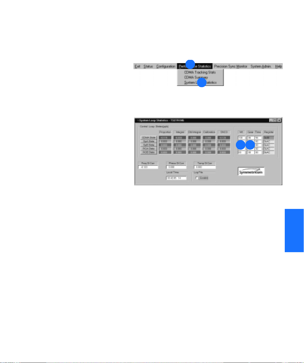
1. Inthemainmenu,click
Performance Statistics.
2. Click System Loop Statistics.
3. View the weight given to each
input for BesTime ensembling
computation.
4. View the stage (gear) in the
time calculation process.
Gears 1, 2, and 3 are warm-up
processes after power-up. Gears 4,
5, and 6 indicate a settling period
when the TimeSource 2700
outputs Stratum 1 signals. Gear 7
indicates steady-state operation.
1
2
3 4
Operation
83
4
4
Page 84

SSSSSSSSSSSS SSSS S SSSSS SSSSSSS S SSS
View Input Performance Statistics
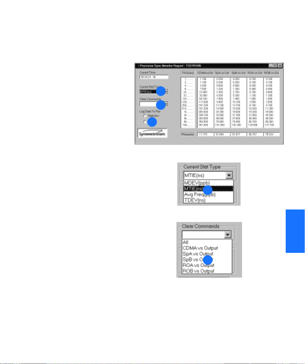
1. Inthemainmenu,clickPrecision
Sync Monitor.
2. View the accumulation period
for the data.
3. View the statistics data, which is
the repor t of the measurement
difference between the provisioned
inputs and the TimeSource 2700
output.
This data can be plotted and
compared against any one of
several timing performance masks,
to gauge the quality of the timing
being received on the input(s).
Timing performance mask(s) and
spreadsheet software are not
available from Symmetricom, and
must be obtained from third party
vendors.
4. View the phase data, which is
the phase offset, in ns, for each
input used in the BesTime
calculation.
1
2 3
5
4
5. Set the log file to contain
statistics data.
84
TimeSource 2700
Page 85
SSSSSSSSSSSS SSSS S SSSSS SSSSSSS S SSS
View Input Performance Statistics (cont’d)
6. Set the log file to contain phase
data.
Data from the screen is written to
the file at every screen update. The
log file may be opened and read
during the logging process, however,
the log file is read-only during the
logging process. The log file is
writteninacomma-delimited(.csv)
data format.
7. Click the pull-down arrow, and
select the type of measurement to
display in the statistics data
columns.
8. Click the pull-down arrow, and
select the data to be cleared in the
statistics data columns: all columns
or a specific column.
7
8
6
7
4
4
8
Operation
85
Page 86

SSSSSSSSSSSS SSSS S SSSSS SSSSSSS S SSS
Set Output Format and Output During Alarm
Note: The setting you choose for
output during alarm will occur
when the system goes into major
alarm.
1. Inthemainmenu,click
Configuration.
2. Click Provision, and highlight
Outputs.
3. Highlight the desired output
format: D4, ESF, or Forced.
4. For D4 output format, select
either AIS on Error or Squelch on
Error, for the alarm method.
5. For ESF output format, select
one of the following alarm
methods: AIS on Error, Squelch on
Error, or SSM.
Note: If SSM is selected, select one
ofthefollowing:STU,ST2,ST3,or
DUS. The recommended setting is
either STU or ST2.
1
2
2
3
4
5
86
TimeSource 2700
Page 87

SSSSSSSSSSSS SSSS S SSSSS SSSSSSS S SSS
Set Output Format and Output During Alarm (cont’d)
6. For Forced output format, select
one of the following alarm
methods: AIS Output, Squelch
Output, D4, or ESF.
Any of the selections under Forced
forces the Span A and B outputs
into a par ticular mode. Forced
mode may be useful for testing and
troubleshooting. Forced mode may
also be useful in applications where
the outputs generated by the
TimeSource 2700, even in major
alarm, may be better than the
alternative (e.g., offices without
additional holdover clocks in a
distribution shelf).
Note: If ESF is selected, select a
quality level for SSM.
SSM messages communicate to
downstream network elements the
timing performance received on an
incoming signal. SSM message
options are as follows:
• Primar y reference source (PRS)
• Synchronization traceability
unknown (STU)
•Stratum2(ST2)
•Stratum3(ST3)
• Do not use for synchronization
(DUS)
•Stratum4(ST4)
•SONETinternalclock(SIC)/
20 ppm
6
4
4
Operation
87
Page 88

SSSSSSSSSSSS SSSS S SSSSS SSSSSSS S SSS
View CDMA Tracking Statistics
1. Inthemainmenu,click
Performance Statistics.
2. Click CDMA Tracking Stats.
3. View the number of minutes the
receiver has been locked during
each hour of the last 24 hours.
Note: On power-up, 60 minutes is
displayed for ever y hour. Actual
data for each hour will appear, as
the system cycles through the first
24 hours of operation after powerup.
4. View the number of minutes the
TimeSource 2700 has been locked
during the last 24 hours.
5. View the percentage of the last
24 hours that the TimeSource
2700 was locked to at least one
CDMA pilot.
The daily success rate must be
greater than 40 percent. If not, refer
to the Troubleshooting chapter.
1
2
3
7 6
4
5
6. Click to update the information.
7. Click to exit.
88
TimeSource 2700
Page 89

SSSSSSSSSSSS SSSS S SSSSS SSSSSSS S SSS
View CDMA Pilot Information
1. Inthemainmenu,click
Performance Statistics.
2. Click CDMA Summary.
3. View information about each
CDMA pilot signal currently being
tracked.
• Pilot: TimeSource 2700 channel
pilot number. The TimeSource
2700 may display data for multiple channels for each pilot signal
received. The actual number of
pilot signals being received is displayed in the Independent Pilot
Count box (described in item 4).
• C/No(dB): Carrier-to-noise ratio.
Measurement of the strength of
the pilot channel relative to
noise.
• Freq Avg(ppb): Deviation of
each pilot signal, in par ts per billion, from the CDMA pilot to the
TimeSource 2700 output.
1
2
3
4
4
• Freq StdDev(ppb): Standard
deviation of each pilot channel, in
parts per billion, from the
CDMA pilot to the TimeSource
2700 output. The smaller the
number, the better the signal,
with 0.01 indicating the best signal, and 0.3 indicating an unacceptable signal.
Operation
89
Page 90

SSSSSSSSSSSS SSSS S SSSSS SSSSSSS S SSS
View CDMA Pilot Information (cont’d)
• FRAIM: (Frequency Receiver
Autonomous Integrity Monitor).
Quality of each pilot channel.
Zero indicates the signal is
acceptable; anything above zero
indicates the signal is unacceptable. On power-up, 3 is the
default which will be displayed
for all pilot channels until the system locks onto a pilot signal.
• Weight: Quality of the pilot
channels relative to each other.
The higher the percentage, the
better the signal. For example, if
pilot #8 displayed 80 percent,
and pilot #2 displayed 20 percent, pilot #8 would be the better signal. If multiple pilots are
acceptable, the TimeSource
2700 ensembles the pilots into a
single composite signal by
weighting the highest quality pilot
with the greatest weighting value.
Weighting assignments are
dynamically adjusted for changes
in pilot signal quality.
3
• Lock: Number of seconds since
the TimeSource 2700 acquired
lock on the pilot channel (count
stops at 10,000). Zero indicates
the system is not locked to the
pilot channel.
90
TimeSource 2700
Page 91

SSSSSSSSSSSS SSSS S SSSSS SSSSSSS S SSS
View CDMA Pilot Information (cont’d)
4. View the number of pilot signals
currently being tracked.
5. Click to star t or stop the log file
for this screen.
Data from the screen is written to
the file every 60 seconds while the
box is checked. The log file may be
opened and read during the logging
process; however, the log file is
read-only during the logging
process. The log file is written to
the host computer disk in a
comma-delimited (.csv) data
format.
6. View the pilot band letter and
channel number in use. The word
“Auto” appearing before the pilot
band letter and channel number
indicates the system locked onto
the displayed pilot via the auto
search method.
4
5 6
Operation
91
4
4
Page 92

SSSSSSSSSSSS SSSS S SSSSS SSSSSSS S SSS
Select Pilot Signal Channel
1. Inthemainmenu,click
Performance Statistics.
2. Click CDMA Summary.
3. Click the pull-down menu.
4. Select one of the bands or Auto
Search.
Caution:
band and frequency for the area
where the TimeSource 2700 is
located, select Auto Search.
5. If a band was selected, select a
channel.
If unsure of the proper
Note: After 20 minutes, if the
TimeSource 2700 cannot find a
CDMA pilot on the selected
channel, it will revert to Auto
Search.
1
2
3
3
4
92
TimeSource 2700
4
5
Page 93

SSSSSSSSSSSS SSSS S SSSSS SSSSSSS S SSS
View Daily Holdover Information
Note: The System Admin drop-
down menu and its selections are
only available to the Administrator
level of security.
1. Inthemainmenu,clickSystem
Admin.
2. Highlight Holdover Information,
and select Daily.
3. Click Select.
4. Highlight Display, then select the
desired input, to see the data for
selected input.
5. View the data of the 4 hour
time period.
The time is indicated as hours of a
24 hour clock.
6. View the average measured
frequency offset during the 4 hour
period, in par ts per billion (ppb).
7. View the predicted frequency
offset during the 4 hour period, in
parts per billion (ppb).
1
2
3
5
6
7
3
4
4
2
4
4
Operation
93
Page 94

SSSSSSSSSSSS SSSS S SSSSS SSSSSSS S SSS
View Daily Holdover Information (cont’d)
8. Click to star t or stop the log file
for this screen.
Data from the screen is written to
the file at ever y screen update while
theboxischecked.Thelogfilemay
be opened and read during the
logging process; however, the log file
is read-only during the logging
process. The log file is written in a
comma-delimited (.csv) data
format.
9. Click the pull-down arrow to
select the number of minutes
between screen updates.
10. View which input is being
measured.
12
11
10
9
8
11. Viewthedrift,inpartsper
billion per day, predicted for this
input during the current 24 hour
period.
12. View the predicted error in ns.
This error can be held for up to
24 hours if the TimeSource 2700
goes into holdover.
94
TimeSource 2700
Page 95

SSSSSSSSSSSS SSSS S SSSSS SSSSSSS S SSS
View Monthly Holdover Information
1. Inthemainmenu,clickSystem
Admin.
2. Highlight Holdover Information,
and select Monthly.
3. Click Select.
4. Highlight Display, then select the
desired input, to see the data for
the selected input.
5. View the data of the 4 day time
period.
Thetimeisindicatedasdaysofa
30 day month.
6. View the average measured
frequency offset during the 4 day
period, in par ts per billion (ppb).
7. View the average predicted time
error during the 4 day period, in
nanoseconds (ns).
1
2
2
3
5
6
7
3
4
4
4
4
Operation
95
Page 96

SSSSSSSSSSSS SSSS S SSSSS SSSSSSS S SSS
View Monthly Holdover Information (cont’d)
8. View which input is being
measured.
9. Click to star t or stop the log file
for this screen.
Data from the screen is written to
the file at ever y screen update while
theboxischecked.Thelogfilemay
be opened and read during the
logging process; however, the log file
is read-only during the logging
process. The log file is written in a
comma-delimited (.csv) data
format.
8
9
96
TimeSource 2700
Page 97

SSSSSSSSSSSS SSSS S SSSSS SSSSSSS S SSS
Reset CDMA Receiver and System
1. Inthemainmenu,clickSystem
Admin.
2. Click Reset.
3. Click to reset the CDMA
receiver processor, and restar t the
pilot signal search.
4. Click to reset the system
processor.
Caution:
Restart BesTime, and clicking
will cause a disruption in ser vice.
5. Click RESET to reset the reset
the selected item, or click Cancel
to ignore any information.
Selecting Reset CDMA,
RESET
1
2
3
,
4
5
5
Operation
97
4
4
Page 98
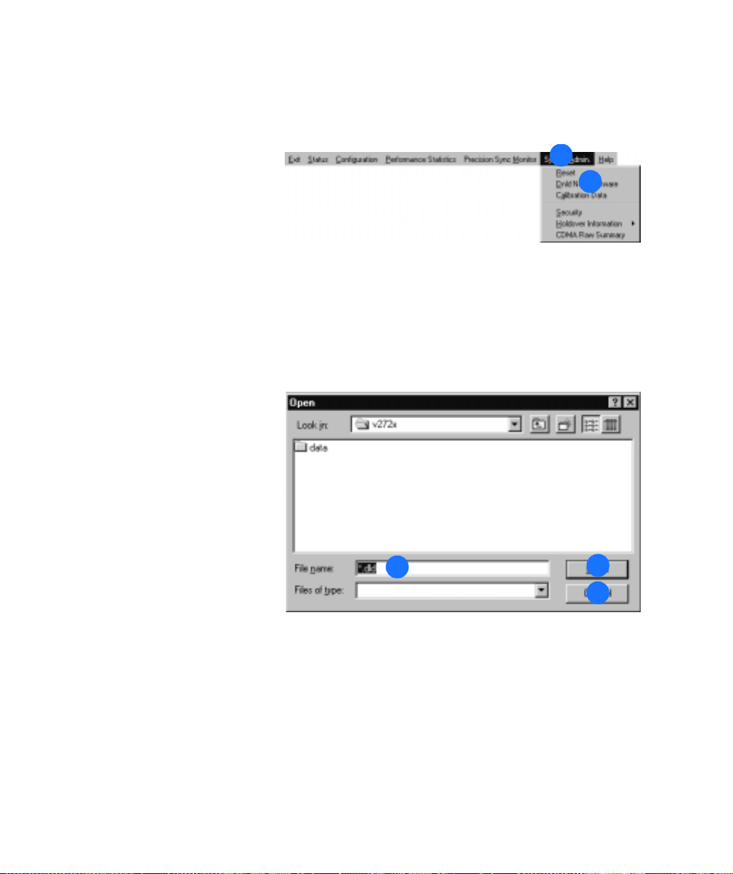
SSSSSSSSSSSS SSSS S SSSSS SSSSSSS S SSS
Download New Software
1. Inthemainmenu,clickSystem
Admin.
2. Click Dnld New Software.
Notes:
a. New software should not be
downloaded over a modem
connection. Use a direct
connection only.
b. TheTimeSource2700does
not lose data during a software
download/upgrade.
c. The TimeSource 2700 enters
bridging mode during the
software loading process, and
exits bridging mode when it
receives its first good CDMA
measurements.
1
2
3. Selectthenameofthefileto
download to the Timesource 2700.
4. Click OK when the desired file
is displayed, or click Cancel to
cancel the current operation.
98
TimeSource 2700
3
4
4
Page 99

SSSSSSSSSSSS SSSS S SSSSS SSSSSSS S SSS
Download New Software (cont’d)
5. Verifythefilenameiscorrect.
6. Verify the baud rate is set to
19200.
7. Click to cancel the current
operation (if desired).
5
8. Click Continue. A progress bar
and messages track the download
process.
9. Once the download is
complete, a message appears. Click
OK.
10. TheTimeSource2700breaks,
then reestablishes, communication
with the host computer, and a
message appears. Click OK.
11. When the BTMONitor main
screen appears, click Exit to exit
the application.
12. Restart BTMONitor to use the
upgraded software.
11
6
7
9
9
10
10
8
4
4
Operation
99
Page 100

SSSSSSSSSSSS SSSS S SSSSS SSSSSSS S SSS
View User Accounts
1. Inthemainmenu,clickSystem
Admin.
2. Click Security.
3. View the list of system users
and their privilege levels.
The privilege levels are
Administration, Management,
Reporting, and None.
4. Click OK or Exit to exit.
1
2
3
4
4
100
TimeSource 2700
 Loading...