

Page 1

TimeProvider 5000
IEEE 1588 Grand Master Clock / NTP Server
User’s Guide
Revision F – May 2012
Part Number 098-00028-000
Page 2

Symmetricom, Inc.
2300 Orchard Parkway
San Jose, CA 95131-1017
U.S.A.
http://www.symmetricom.com
Copyright © 2012 Symmetricom, Inc.
All rights reserved. Printed in U.S.A.
All product names, service marks, trademarks, and registered trademarks
used in this document are the property of their respective owners.
Page 3

Contents
How to Use This Guide
Purpose of This Guide . . . . . . . . . . . . . . . . . . . . . . . . . . . . . . . . . . . . . . . . . . .22
Who Should Read This Guide. . . . . . . . . . . . . . . . . . . . . . . . . . . . . . . . . . . . . .22
Structure of This Guide. . . . . . . . . . . . . . . . . . . . . . . . . . . . . . . . . . . . . . . . . . .23
Conventions Used in This Guide. . . . . . . . . . . . . . . . . . . . . . . . . . . . . . . . . . . .24
Warnings, Cautions, Recommendations, and Notes . . . . . . . . . . . . . . . . . . . .25
Related Documents and Information. . . . . . . . . . . . . . . . . . . . . . . . . . . . . . . . .26
Where to Find Answers to Product and Document Questions . . . . . . . . . . . . .26
What’s New In This Guide. . . . . . . . . . . . . . . . . . . . . . . . . . . . . . . . . . . . . . . . .26
Chapter 1 Overview
Overview. . . . . . . . . . . . . . . . . . . . . . . . . . . . . . . . . . . . . . . . . . . . . . . . . . . . . .30
TimeProvider 5000 Features . . . . . . . . . . . . . . . . . . . . . . . . . . . . . . . . . .30
Software Options . . . . . . . . . . . . . . . . . . . . . . . . . . . . . . . . . . . . . . . . . . .31
Security Features . . . . . . . . . . . . . . . . . . . . . . . . . . . . . . . . . . . . . . . . . . .32
TimeProvider 5000 Connections. . . . . . . . . . . . . . . . . . . . . . . . . . . . . . . . . . . .33
UTI Input and Output Connections . . . . . . . . . . . . . . . . . . . . . . . . . . . . . .33
Communications Connections . . . . . . . . . . . . . . . . . . . . . . . . . . . . . . . . .34
Output Connections . . . . . . . . . . . . . . . . . . . . . . . . . . . . . . . . . . . . . . . . .37
Input Connections. . . . . . . . . . . . . . . . . . . . . . . . . . . . . . . . . . . . . . . . . . .40
Power and Ground Connections. . . . . . . . . . . . . . . . . . . . . . . . . . . . . . . .42
Physical Description . . . . . . . . . . . . . . . . . . . . . . . . . . . . . . . . . . . . . . . . . . . . .43
Functional Description. . . . . . . . . . . . . . . . . . . . . . . . . . . . . . . . . . . . . . . . . . . .45
TimeProvider 5000 Expansion Shelf System . . . . . . . . . . . . . . . . . . . . . .45
IMC Module LEDs. . . . . . . . . . . . . . . . . . . . . . . . . . . . . . . . . . . . . . . . . . .51
IOC Module LEDs. . . . . . . . . . . . . . . . . . . . . . . . . . . . . . . . . . . . . . . . . . .51
Expansion Shelf LEDs . . . . . . . . . . . . . . . . . . . . . . . . . . . . . . . . . . . . . . .51
Communication Ports . . . . . . . . . . . . . . . . . . . . . . . . . . . . . . . . . . . . . . . .52
Synchronization and Timing Inputs. . . . . . . . . . . . . . . . . . . . . . . . . . . . . .52
Synchronization and Timing Outputs . . . . . . . . . . . . . . . . . . . . . . . . . . . .52
System Inputs and Outputs. . . . . . . . . . . . . . . . . . . . . . . . . . . . . . . . . . . .53
TP E10 Expansion Shelf System Outputs . . . . . . . . . . . . . . . . . . . . . . . .54
TP E30 Expansion Shelf System Outputs . . . . . . . . . . . . . . . . . . . . . . . .54
Expansion Shelf ID Switch . . . . . . . . . . . . . . . . . . . . . . . . . . . . . . . . . . . .54
Configuration Management. . . . . . . . . . . . . . . . . . . . . . . . . . . . . . . . . . . . . . . .55
098-00028-000 Revision F – May, 2012 TimeProvider 5000 User’s Guide 3
Page 4

Table of Contents
Alarms. . . . . . . . . . . . . . . . . . . . . . . . . . . . . . . . . . . . . . . . . . . . . . . . . . . . . . . .55
Chapter 2 Installing
Getting Started . . . . . . . . . . . . . . . . . . . . . . . . . . . . . . . . . . . . . . . . . . . . . . . . .58
Security Considerations for TP5000 Installation. . . . . . . . . . . . . . . . . . . .58
Site Survey . . . . . . . . . . . . . . . . . . . . . . . . . . . . . . . . . . . . . . . . . . . . . . . .58
Installation Tools and Equipment . . . . . . . . . . . . . . . . . . . . . . . . . . . . . . .59
Unpacking the Unit . . . . . . . . . . . . . . . . . . . . . . . . . . . . . . . . . . . . . . . . . . . . . .60
Rack Mounting the Chassis . . . . . . . . . . . . . . . . . . . . . . . . . . . . . . . . . . . . . . .62
Rack Mounting the TimeProvider 5000 Main Shelf. . . . . . . . . . . . . . . . . .62
Rack Mounting the TP E10 & TP E30 Expansion Shelves. . . . . . . . . . . .64
Working With Modules . . . . . . . . . . . . . . . . . . . . . . . . . . . . . . . . . . . . . . . . . . .67
Handling Modules. . . . . . . . . . . . . . . . . . . . . . . . . . . . . . . . . . . . . . . . . . .67
Inserting Modules . . . . . . . . . . . . . . . . . . . . . . . . . . . . . . . . . . . . . . . . . . .68
Removing Modules. . . . . . . . . . . . . . . . . . . . . . . . . . . . . . . . . . . . . . . . . .68
Signal Connections. . . . . . . . . . . . . . . . . . . . . . . . . . . . . . . . . . . . . . . . . . . . . .68
Communications Connections . . . . . . . . . . . . . . . . . . . . . . . . . . . . . . . . .69
TP 5000 Synchronization and Timing Connections . . . . . . . . . . . . . . . . .71
TimeProvider E10 Synchronization and Timing Connections. . . . . . . . . .81
TimeProvider E30 Synchronization and Timing Connections. . . . . . . . . .82
Connecting the GPS/GNSS Antenna . . . . . . . . . . . . . . . . . . . . . . . . . . . . . . . .83
Setting Shelf ID on Expansion Shelves. . . . . . . . . . . . . . . . . . . . . . . . . . . . . . .84
Making Ground and Power Connections . . . . . . . . . . . . . . . . . . . . . . . . . . . . .84
Ground Connections. . . . . . . . . . . . . . . . . . . . . . . . . . . . . . . . . . . . . . . . .85
Power Connections. . . . . . . . . . . . . . . . . . . . . . . . . . . . . . . . . . . . . . . . . .86
Testing Power Connections . . . . . . . . . . . . . . . . . . . . . . . . . . . . . . . . . . .88
Installation Check List. . . . . . . . . . . . . . . . . . . . . . . . . . . . . . . . . . . . . . . . . . . .89
Applying Power to the TimeProvider 5000 . . . . . . . . . . . . . . . . . . . . . . . . . . . .89
Normal Power Up Indications . . . . . . . . . . . . . . . . . . . . . . . . . . . . . . . . . .89
Chapter 3 CLI Commands and SNMP
CLI Overview. . . . . . . . . . . . . . . . . . . . . . . . . . . . . . . . . . . . . . . . . . . . . . . . . . .94
TimeProvider 5000 CLI Command Conventions . . . . . . . . . . . . . . . . . . .95
CLI Command Keyboard Usage. . . . . . . . . . . . . . . . . . . . . . . . . . . . . . . .95
Command Line Format. . . . . . . . . . . . . . . . . . . . . . . . . . . . . . . . . . . . . . .96
Command User Levels . . . . . . . . . . . . . . . . . . . . . . . . . . . . . . . . . . . . . . .97
4 TimeProvider 5000 User’s Guide 098-00028-000 Revision F – May, 2012
Page 5

Table of Contents
TimeProvider 5000 CLI Command Set. . . . . . . . . . . . . . . . . . . . . . . . . . . . . . .97
Command Syntax: . . . . . . . . . . . . . . . . . . . . . . . . . . . . . . . . . . . . . . . . .226
Command Syntax: . . . . . . . . . . . . . . . . . . . . . . . . . . . . . . . . . . . . . . . . .227
Simple Network Management Protocol (SNMP). . . . . . . . . . . . . . . . . . . . . . .266
Management Information Base. . . . . . . . . . . . . . . . . . . . . . . . . . . . . . . .266
Public MIBs. . . . . . . . . . . . . . . . . . . . . . . . . . . . . . . . . . . . . . . . . . . . . . .267
Private MIBs . . . . . . . . . . . . . . . . . . . . . . . . . . . . . . . . . . . . . . . . . . . . . .268
Chapter 4 Provisioning
Establishing a Connection to the TimeProvider 5000. . . . . . . . . . . . . . . . . . .272
Communicating Through the Serial Port. . . . . . . . . . . . . . . . . . . . . . . . .272
Communicating Through the Ethernet Port . . . . . . . . . . . . . . . . . . . . . .273
Managing the User Access List. . . . . . . . . . . . . . . . . . . . . . . . . . . . . . . . . . . .274
Logging In. . . . . . . . . . . . . . . . . . . . . . . . . . . . . . . . . . . . . . . . . . . . . . . .275
Adding a User. . . . . . . . . . . . . . . . . . . . . . . . . . . . . . . . . . . . . . . . . . . . .275
Deleting A User. . . . . . . . . . . . . . . . . . . . . . . . . . . . . . . . . . . . . . . . . . . .276
Displaying Current Users and User Access Levels . . . . . . . . . . . . . . . .276
Changing a User’s Password . . . . . . . . . . . . . . . . . . . . . . . . . . . . . . . . .277
Changing a User’s Access Level . . . . . . . . . . . . . . . . . . . . . . . . . . . . . .278
Provisioning for a RADIUS Server . . . . . . . . . . . . . . . . . . . . . . . . . . . . . . . . .279
Provisioning the TP5000 for Login Authentication . . . . . . . . . . . . . . . . .279
Configuring the RADIUS Server . . . . . . . . . . . . . . . . . . . . . . . . . . . . . . .279
Provisioning the Ethernet Ports. . . . . . . . . . . . . . . . . . . . . . . . . . . . . . . . . . . .280
Provisioning IMC Ethernet Port. . . . . . . . . . . . . . . . . . . . . . . . . . . . . . . .280
Provisioning IOC Ethernet Ports. . . . . . . . . . . . . . . . . . . . . . . . . . . . . . .282
Provisioning VLAN . . . . . . . . . . . . . . . . . . . . . . . . . . . . . . . . . . . . . . . . . . . . .287
Provisioning PTP. . . . . . . . . . . . . . . . . . . . . . . . . . . . . . . . . . . . . . . . . . . . . . .291
Packet Service Modes . . . . . . . . . . . . . . . . . . . . . . . . . . . . . . . . . . . . . .291
PTP Profiles . . . . . . . . . . . . . . . . . . . . . . . . . . . . . . . . . . . . . . . . . . . . . .292
PTP Parameters . . . . . . . . . . . . . . . . . . . . . . . . . . . . . . . . . . . . . . . . . . .295
Management Addressing Mode . . . . . . . . . . . . . . . . . . . . . . . . . . . . . . .299
Two-Step Clock Mode. . . . . . . . . . . . . . . . . . . . . . . . . . . . . . . . . . . . . . .300
Provisioning NTP . . . . . . . . . . . . . . . . . . . . . . . . . . . . . . . . . . . . . . . . . . . . . .308
Provisioning an IOC Port as NTP Server . . . . . . . . . . . . . . . . . . . . . . . .309
098-00028-000 Revision F – May, 2012 TimeProvider 5000 User’s Guide 5
Page 6

Table of Contents
Provisioning the Input Reference . . . . . . . . . . . . . . . . . . . . . . . . . . . . . . . . . .310
Setting Reference Mode. . . . . . . . . . . . . . . . . . . . . . . . . . . . . . . . . . . . .310
Setting Reference Criteria. . . . . . . . . . . . . . . . . . . . . . . . . . . . . . . . . . . .311
Setting Input Priority Values . . . . . . . . . . . . . . . . . . . . . . . . . . . . . . . . . .312
Setting GPS Port as Reference . . . . . . . . . . . . . . . . . . . . . . . . . . . . . . .313
Setting GNSS Port as Reference . . . . . . . . . . . . . . . . . . . . . . . . . . . . . .315
Setting a 1PPS+TOD Input as Reference. . . . . . . . . . . . . . . . . . . . . . . .316
Setting an E1/T1 Input as Reference . . . . . . . . . . . . . . . . . . . . . . . . . . .317
Provisioning the Programmable E1/T1 Inputs. . . . . . . . . . . . . . . . . . . . . . . . .318
Synchronization Status Message (SSM) . . . . . . . . . . . . . . . . . . . . . . . .318
CRC State. . . . . . . . . . . . . . . . . . . . . . . . . . . . . . . . . . . . . . . . . . . . . . . .320
Provisioning E1 Inputs . . . . . . . . . . . . . . . . . . . . . . . . . . . . . . . . . . . . . .321
Provisioning T1 Inputs . . . . . . . . . . . . . . . . . . . . . . . . . . . . . . . . . . . . . .322
Provisioning the 1PPS+TOD Inputs . . . . . . . . . . . . . . . . . . . . . . . . . . . . . . . .324
Provisioning the Programmable E1/T1 Outputs . . . . . . . . . . . . . . . . . . . . . . .325
Provisioning T1 Outputs . . . . . . . . . . . . . . . . . . . . . . . . . . . . . . . . . . . . .327
Provisioning Output Generation Behavior. . . . . . . . . . . . . . . . . . . . . . . .328
Provisioning the Dedicated Outputs . . . . . . . . . . . . . . . . . . . . . . . . . . . . . . . .330
Provisioning E1 Outputs . . . . . . . . . . . . . . . . . . . . . . . . . . . . . . . . . . . . .330
Provisioning Output Generation Behavior. . . . . . . . . . . . . . . . . . . . . . . .331
Provisioning the 10MHz & 1PPS Outputs. . . . . . . . . . . . . . . . . . . . . . . .332
Provisioning TP 5000 for Expansion Shelf . . . . . . . . . . . . . . . . . . . . . . . . . . .333
Verify Expansion Configuration. . . . . . . . . . . . . . . . . . . . . . . . . . . . . . . .334
Provisioning DTI / Ethernet Port on IMC Card . . . . . . . . . . . . . . . . . . . .334
Provisioning DTI Ports on IO Card . . . . . . . . . . . . . . . . . . . . . . . . . . . . .334
Provisioning Expansion Shelf E1 / 1PPS+TOD Outputs. . . . . . . . . . . . . . . . .336
Provisioning DTI for an Expansion Shelf . . . . . . . . . . . . . . . . . . . . . . . .336
Provisioning E1 Output Signals for Expansion Shelf . . . . . . . . . . . . . . .336
Provisioning 1PPS +TOD Outputs for Expansion Shelf . . . . . . . . . . . . .339
Provisioning Expansion Shelf PTP/SyncE Outputs. . . . . . . . . . . . . . . . . . . . .341
Provisioning DTI for an Expansion Shelf . . . . . . . . . . . . . . . . . . . . . . . .341
Provisioning PTP Outputs for the Expansion Shelf. . . . . . . . . . . . . . . . .341
Provisioning SyncE Outputs for the Expansion Shelf. . . . . . . . . . . . . . .344
Setting the System Date and Time . . . . . . . . . . . . . . . . . . . . . . . . . . . . . . . . .345
Provisioning Alarms . . . . . . . . . . . . . . . . . . . . . . . . . . . . . . . . . . . . . . . . . . . .346
Disabling Specific Alarms . . . . . . . . . . . . . . . . . . . . . . . . . . . . . . . . . . . .347
Showing Current Alarm Settings. . . . . . . . . . . . . . . . . . . . . . . . . . . . . . .347
Showing Current Alarms. . . . . . . . . . . . . . . . . . . . . . . . . . . . . . . . . . . . .348
Displaying Alarm and Unit Status . . . . . . . . . . . . . . . . . . . . . . . . . . . . . .348
6 TimeProvider 5000 User’s Guide 098-00028-000 Revision F – May, 2012
Page 7

Table of Contents
Saving and Restoring Provisioning Data. . . . . . . . . . . . . . . . . . . . . . . . . . . . .349
Backing up Provisioning Data. . . . . . . . . . . . . . . . . . . . . . . . . . . . . . . . .350
Restoring Provisioning Data . . . . . . . . . . . . . . . . . . . . . . . . . . . . . . . . . .352
Provisioning for SNMP . . . . . . . . . . . . . . . . . . . . . . . . . . . . . . . . . . . . . . . . . .354
Enabling the SNMP Option. . . . . . . . . . . . . . . . . . . . . . . . . . . . . . . . . . .355
Selecting MIB Versions. . . . . . . . . . . . . . . . . . . . . . . . . . . . . . . . . . . . . .356
Adding or Deleting a Manager IP Address . . . . . . . . . . . . . . . . . . . . . . .356
Provisioning to Generate v2 Traps . . . . . . . . . . . . . . . . . . . . . . . . . . . . .356
Provisioning to Generate v3 Traps . . . . . . . . . . . . . . . . . . . . . . . . . . . . .356
Adding and Removing v2 Communities . . . . . . . . . . . . . . . . . . . . . . . . .357
Adding and Removing SNMP v3 Users . . . . . . . . . . . . . . . . . . . . . . . . .357
Adding and Removing SNMP v3 Trap Users . . . . . . . . . . . . . . . . . . . . .358
Chapter 5 Operating
Logging In And Out. . . . . . . . . . . . . . . . . . . . . . . . . . . . . . . . . . . . . . . . . . . . .360
Adding And Deleting Users. . . . . . . . . . . . . . . . . . . . . . . . . . . . . . . . . . . . . . .360
Saving Present Configuration To Non-volatile Memory . . . . . . . . . . . . . . . . .360
Restoring Default Configuration . . . . . . . . . . . . . . . . . . . . . . . . . . . . . . . . . . .360
Determining Status . . . . . . . . . . . . . . . . . . . . . . . . . . . . . . . . . . . . . . . . . . . . .361
Forcing Unit To Send New Time in Time Reference Mode. . . . . . . . . . . . . . .361
Switching Active And Standby IOC Cards . . . . . . . . . . . . . . . . . . . . . . . . . . .362
Manually Switching IOC Cards. . . . . . . . . . . . . . . . . . . . . . . . . . . . . . . .362
Automatic IOC Card Switches . . . . . . . . . . . . . . . . . . . . . . . . . . . . . . . .362
Impact of IOC Card Switches on IO Card Outputs . . . . . . . . . . . . . . . . .363
Displaying Logs. . . . . . . . . . . . . . . . . . . . . . . . . . . . . . . . . . . . . . . . . . . . . . . .363
Displaying Alarms Log . . . . . . . . . . . . . . . . . . . . . . . . . . . . . . . . . . . . . .363
Displaying Events Log . . . . . . . . . . . . . . . . . . . . . . . . . . . . . . . . . . . . . .363
Restarting the TimeProvider 5000 . . . . . . . . . . . . . . . . . . . . . . . . . . . . . . . . .364
Managing PTP Clients . . . . . . . . . . . . . . . . . . . . . . . . . . . . . . . . . . . . . . . . . .365
Configuring PTP Clients . . . . . . . . . . . . . . . . . . . . . . . . . . . . . . . . . . . . .366
Monitoring PTP Client Performance . . . . . . . . . . . . . . . . . . . . . . . . . . . .367
Monitoring PTP Client Alarm / Event Information . . . . . . . . . . . . . . . . . .368
Upgrading PTP Client Firmware. . . . . . . . . . . . . . . . . . . . . . . . . . . . . . .369
Chapter 6 Maintenance and Troubleshooting
Preventive Maintenance . . . . . . . . . . . . . . . . . . . . . . . . . . . . . . . . . . . . . . . . .372
Safety Considerations. . . . . . . . . . . . . . . . . . . . . . . . . . . . . . . . . . . . . . . . . . .372
098-00028-000 Revision F – May, 2012 TimeProvider 5000 User’s Guide 7
Page 8

Table of Contents
ESD Considerations . . . . . . . . . . . . . . . . . . . . . . . . . . . . . . . . . . . . . . . . . . . .372
Troubleshooting . . . . . . . . . . . . . . . . . . . . . . . . . . . . . . . . . . . . . . . . . . . . . . .373
Diagnosing the IOC - Reading LED Conditions . . . . . . . . . . . . . . . . . . .376
Diagnosing the IMC - Reading LED Conditions . . . . . . . . . . . . . . . . . . .380
Diagnosing the Expansion Shelf- Reading LED Conditions . . . . . . . . . .382
Repairing the TimeProvider 5000 . . . . . . . . . . . . . . . . . . . . . . . . . . . . . . . . . .384
Removing the IOC . . . . . . . . . . . . . . . . . . . . . . . . . . . . . . . . . . . . . . . . .385
Replacing the IOC. . . . . . . . . . . . . . . . . . . . . . . . . . . . . . . . . . . . . . . . . .385
Replacing the IMC . . . . . . . . . . . . . . . . . . . . . . . . . . . . . . . . . . . . . . . . .388
Upgrading the Firmware . . . . . . . . . . . . . . . . . . . . . . . . . . . . . . . . . . . . . . . . .389
TP5000 Upgrade - Loss of Outputs . . . . . . . . . . . . . . . . . . . . . . . . . . . .391
TP5000 with Redundant IOC Modules v1.2.3 - No Loss of Outputs. . . .392
TP5000 with Redundant IOC Modules v1.1.8 - No Loss of Outputs. . . .394
Upgrading an Expansion Shelf . . . . . . . . . . . . . . . . . . . . . . . . . . . . . . . .396
TimeProvider 5000 Part Numbers. . . . . . . . . . . . . . . . . . . . . . . . . . . . . . . . . .397
System and Accessory Part Numbers . . . . . . . . . . . . . . . . . . . . . . . . . .397
GPS Antenna . . . . . . . . . . . . . . . . . . . . . . . . . . . . . . . . . . . . . . . . . . . . .400
Returning the TimeProvider 5000. . . . . . . . . . . . . . . . . . . . . . . . . . . . . . . . . .401
Repacking the Unit . . . . . . . . . . . . . . . . . . . . . . . . . . . . . . . . . . . . . . . . .401
Equipment Return Procedure . . . . . . . . . . . . . . . . . . . . . . . . . . . . . . . . .401
User’s Guide Updates. . . . . . . . . . . . . . . . . . . . . . . . . . . . . . . . . . . . . . . . . . .402
Contacting Technical Support. . . . . . . . . . . . . . . . . . . . . . . . . . . . . . . . . . . . .402
Appendix A System Messages
Message provisioning . . . . . . . . . . . . . . . . . . . . . . . . . . . . . . . . . . . . . . . . . . .406
Facility codes . . . . . . . . . . . . . . . . . . . . . . . . . . . . . . . . . . . . . . . . . . . . .406
Severity codes . . . . . . . . . . . . . . . . . . . . . . . . . . . . . . . . . . . . . . . . . . . .406
System Notification Messages . . . . . . . . . . . . . . . . . . . . . . . . . . . . . . . . . . . .407
8 TimeProvider 5000 User’s Guide 098-00028-000 Revision F – May, 2012
Page 9

Table of Contents
Appendix B Specifications and Factory Defaults
Specifications . . . . . . . . . . . . . . . . . . . . . . . . . . . . . . . . . . . . . . . . . . . . . . . . .430
Mechanical . . . . . . . . . . . . . . . . . . . . . . . . . . . . . . . . . . . . . . . . . . . . . . .430
Environmental. . . . . . . . . . . . . . . . . . . . . . . . . . . . . . . . . . . . . . . . . . . . .430
Power . . . . . . . . . . . . . . . . . . . . . . . . . . . . . . . . . . . . . . . . . . . . . . . . . . .431
Serial Port. . . . . . . . . . . . . . . . . . . . . . . . . . . . . . . . . . . . . . . . . . . . . . . .432
LAN Port . . . . . . . . . . . . . . . . . . . . . . . . . . . . . . . . . . . . . . . . . . . . . . . . .432
Input Signals. . . . . . . . . . . . . . . . . . . . . . . . . . . . . . . . . . . . . . . . . . . . . .432
Output Signals . . . . . . . . . . . . . . . . . . . . . . . . . . . . . . . . . . . . . . . . . . . .439
Clocks. . . . . . . . . . . . . . . . . . . . . . . . . . . . . . . . . . . . . . . . . . . . . . . . . . .448
Factory Defaults . . . . . . . . . . . . . . . . . . . . . . . . . . . . . . . . . . . . . . . . . . . . . . .449
TP 5000 Main Shelf Defaults . . . . . . . . . . . . . . . . . . . . . . . . . . . . . . . . .449
TP E10 Expansion Shelf Defaults. . . . . . . . . . . . . . . . . . . . . . . . . . . . . .460
TP E30 Expansion Shelf Defaults. . . . . . . . . . . . . . . . . . . . . . . . . . . . . .464
Alarm Default Values . . . . . . . . . . . . . . . . . . . . . . . . . . . . . . . . . . . . . . .465
Appendix C Installing the GPS Antenna
Antenna Kits and Accessories . . . . . . . . . . . . . . . . . . . . . . . . . . . . . . . . . . . .468
Selecting the Proper Gain Antenna . . . . . . . . . . . . . . . . . . . . . . . . . . . .468
Transient Eliminators . . . . . . . . . . . . . . . . . . . . . . . . . . . . . . . . . . . . . . .470
GPS L1 Inline Amplifier. . . . . . . . . . . . . . . . . . . . . . . . . . . . . . . . . . . . . .471
Antenna Coaxial Cables . . . . . . . . . . . . . . . . . . . . . . . . . . . . . . . . . . . . .472
Antenna Installation. . . . . . . . . . . . . . . . . . . . . . . . . . . . . . . . . . . . . . . . . . . . .472
Antenna Connection Overview . . . . . . . . . . . . . . . . . . . . . . . . . . . . . . . .473
Planning the Installation . . . . . . . . . . . . . . . . . . . . . . . . . . . . . . . . . . . . .473
Antenna Installation Tools and Materials . . . . . . . . . . . . . . . . . . . . . . . .476
Cutting Antenna Cables . . . . . . . . . . . . . . . . . . . . . . . . . . . . . . . . . . . . .476
Installing the Antenna . . . . . . . . . . . . . . . . . . . . . . . . . . . . . . . . . . . . . . .477
Connecting the Cable to the Antenna. . . . . . . . . . . . . . . . . . . . . . . . . . .477
Installing the Transient Eliminator. . . . . . . . . . . . . . . . . . . . . . . . . . . . . .478
Installing the Antenna Cable. . . . . . . . . . . . . . . . . . . . . . . . . . . . . . . . . .479
Connecting the GPS Antenna. . . . . . . . . . . . . . . . . . . . . . . . . . . . . . . . .479
Antenna Installation Completeness Checklist. . . . . . . . . . . . . . . . . . . . .480
Appendix D Redundant IOC Cards
Overview. . . . . . . . . . . . . . . . . . . . . . . . . . . . . . . . . . . . . . . . . . . . . . . . . . . . .482
098-00028-000 Revision F – May, 2012 TimeProvider 5000 User’s Guide 9
Page 10

Table of Contents
Parameters with IOC Card Redundancy. . . . . . . . . . . . . . . . . . . . . . . . . . . . .483
IP Addresses and MAC Addresses with Independent Ports. . . . . . . . . .483
IP Addresses and MAC Addresses with Port Redundancy . . . . . . . . . .483
Clock IDs. . . . . . . . . . . . . . . . . . . . . . . . . . . . . . . . . . . . . . . . . . . . . . . . .483
Possible Conflicts With Clock IDs and IP Addresses . . . . . . . . . . . . . . .485
Causes of Switchovers Between IOC Cards. . . . . . . . . . . . . . . . . . . . . . . . . .485
Emergency Switchovers . . . . . . . . . . . . . . . . . . . . . . . . . . . . . . . . . . . . .486
Planned Switchovers . . . . . . . . . . . . . . . . . . . . . . . . . . . . . . . . . . . . . . .486
Setting the Active IOC Card at Power Up. . . . . . . . . . . . . . . . . . . . . . . . . . . .487
IOC States . . . . . . . . . . . . . . . . . . . . . . . . . . . . . . . . . . . . . . . . . . . . . . .488
Output Performance During Switchover . . . . . . . . . . . . . . . . . . . . . . . . . . . . .490
IOC Card Redundancy-Related CLI Commands . . . . . . . . . . . . . . . . . . . . . .491
Appendix E Software Licenses
Third-Party Software. . . . . . . . . . . . . . . . . . . . . . . . . . . . . . . . . . . . . . . . . . . .494
Appendix F PTP Probe Option
Overview. . . . . . . . . . . . . . . . . . . . . . . . . . . . . . . . . . . . . . . . . . . . . . . . . . . . .495
Requirements for Measurements . . . . . . . . . . . . . . . . . . . . . . . . . . . . . . . . . .498
Optional Equipment . . . . . . . . . . . . . . . . . . . . . . . . . . . . . . . . . . . . . . . .498
Installing the Probe . . . . . . . . . . . . . . . . . . . . . . . . . . . . . . . . . . . . . . . . . . . . .499
Connecting PTP Signals to Measure . . . . . . . . . . . . . . . . . . . . . . . . . . .499
Controlling the Probe With TimeMonitor PDV. . . . . . . . . . . . . . . . . . . . . . . . .501
Anatomy of the GUI Main Screen . . . . . . . . . . . . . . . . . . . . . . . . . . . . . .501
Functions of TimeMonitor PDV. . . . . . . . . . . . . . . . . . . . . . . . . . . . . . . .506
Entering CLI Commands Manually with TimeMonitor PDV . . . . . . . . . .508
Installing TimeMonitor. . . . . . . . . . . . . . . . . . . . . . . . . . . . . . . . . . . . . . .510
Provisioning the Probe . . . . . . . . . . . . . . . . . . . . . . . . . . . . . . . . . . . . . . . . . .510
Establish a Connection to the TP 5000 Probe . . . . . . . . . . . . . . . . . . . .510
Enable the Probe Option on the TP 5000. . . . . . . . . . . . . . . . . . . . . . . .511
Enable Port as a PTP Probe. . . . . . . . . . . . . . . . . . . . . . . . . . . . . . . . . .512
Return Port to Grandmaster Mode . . . . . . . . . . . . . . . . . . . . . . . . . . . . .513
Set the IP Address for Probe MGMT Port. . . . . . . . . . . . . . . . . . . . . . . .513
Set Probe IP Address . . . . . . . . . . . . . . . . . . . . . . . . . . . . . . . . . . . . . . .515
Set Grandmaster PTP IP Address . . . . . . . . . . . . . . . . . . . . . . . . . . . . .517
Set Synchronization Interval. . . . . . . . . . . . . . . . . . . . . . . . . . . . . . . . . .518
Set Lease Duration. . . . . . . . . . . . . . . . . . . . . . . . . . . . . . . . . . . . . . . . .518
Operating the Probe . . . . . . . . . . . . . . . . . . . . . . . . . . . . . . . . . . . . . . . . . . . .520
10 TimeProvider 5000 User’s Guide 098-00028-000 Revision F – May, 2012
Page 11

Table of Contents
Probe Data . . . . . . . . . . . . . . . . . . . . . . . . . . . . . . . . . . . . . . . . . . . . . . . . . . .522
Saving Probe Data . . . . . . . . . . . . . . . . . . . . . . . . . . . . . . . . . . . . . . . . .524
Analyzing Probe Data . . . . . . . . . . . . . . . . . . . . . . . . . . . . . . . . . . . . . . . . . . .524
Index. . . . . . . . . . . . . . . . . . . . . . . . . . . . . . . . . . . . . . . . . . . . . . . . . . . . . . . . . .525
098-00028-000 Revision F – May, 2012 TimeProvider 5000 User’s Guide 11
Page 12

Table of Contents
12 TimeProvider 5000 User’s Guide 098-00028-000 Revision F – May, 2012
Page 13

Figures
1-1 TimeProvider 5000 Connectors and LEDs . . . . . . . . . . . . . . . . . . . . . . . . .33
1-2 TimeProvider 5000 - Expansion Version Connectors and LEDs. . . . . . . . .33
1-3 IMC Module: Versions -01 through -05 . . . . . . . . . . . . . . . . . . . . . . . . . . . .36
1-4 Serial Port Male Connector Pins . . . . . . . . . . . . . . . . . . . . . . . . . . . . . . . . .37
1-5 E1 Versions of I/O Module. . . . . . . . . . . . . . . . . . . . . . . . . . . . . . . . . . . . . .39
1-6 T1 and Expansion Versions of I/O Module . . . . . . . . . . . . . . . . . . . . . . . . .39
1-7 PTP Output Connections. . . . . . . . . . . . . . . . . . . . . . . . . . . . . . . . . . . . . . .40
1-8 TimeProvider 5000 Power and Ground. . . . . . . . . . . . . . . . . . . . . . . . . . . .42
1-9 TimeProvider E10 Power amd Ground . . . . . . . . . . . . . . . . . . . . . . . . . . . .42
1-10 TimeProvider E30 Power and Ground. . . . . . . . . . . . . . . . . . . . . . . . . . . . .42
1-11 TimeProvider 5000 Modules and Power Connections. . . . . . . . . . . . . . . . .44
1-12 TimeProvider E10 Expansion Shelf Connections . . . . . . . . . . . . . . . . . . . .44
1-13 TimeProvider E30 Expansion Shelf Connections . . . . . . . . . . . . . . . . . . . .44
1-14 TimeProvider 5000 Block Diagram . . . . . . . . . . . . . . . . . . . . . . . . . . . . . . .45
1-15 Expansion Connector on Expansion Shelf . . . . . . . . . . . . . . . . . . . . . . . . .46
1-16 Physical Interfaces of TP 5000 with Two Expansion Shelves . . . . . . . . . . .47
1-17 TimeProvider E10 SyncE/PTP Expansion Shelf Block Diagram . . . . . . . . .47
1-18 TimeProvider E30 E1/1PPS+TOD Expansion Shelf Block Diagram . . . . . .48
1-19 Expansion Connections for TP 5000 with a Single Expansion Shelf. . . . . .49
1-20 Expansion Connections for TP 5000 with 5 Expansion Shelves. . . . . . . . .50
1-21 Shelf ID Selector . . . . . . . . . . . . . . . . . . . . . . . . . . . . . . . . . . . . . . . . . . . . .54
2-1 TP 5000 - Location of Product Label. . . . . . . . . . . . . . . . . . . . . . . . . . . . . .61
2-2 TP E10 - Location of Product Label. . . . . . . . . . . . . . . . . . . . . . . . . . . . . . .61
2-3 TP E30 - Location of Product Label. . . . . . . . . . . . . . . . . . . . . . . . . . . . . . .61
2-4 TP 5000 Mounting Hole Placements. . . . . . . . . . . . . . . . . . . . . . . . . . . . . .63
2-5 TP 5000 Chassis Dimensions - Front View. . . . . . . . . . . . . . . . . . . . . . . . .63
2-6 TP 5000 Chassis Dimensions - Top View . . . . . . . . . . . . . . . . . . . . . . . . . .63
2-7 Rack Mounting the TimeProvider 5000 . . . . . . . . . . . . . . . . . . . . . . . . . . . .64
2-8 TP E10 and TP E30 Mounting Hole Placements - Side View . . . . . . . . . . .65
2-9 TP E10 Chassis Dimensions - Front View. . . . . . . . . . . . . . . . . . . . . . . . . .65
2-10 TP E30 Chassis Dimensions - Front View. . . . . . . . . . . . . . . . . . . . . . . . . .65
2-11 TP E10 and TP E30 Chassis Dimensions - Top View. . . . . . . . . . . . . . . . .66
2-12 Rack Mounting the TP E10 Expansion Shelf. . . . . . . . . . . . . . . . . . . . . . . .66
2-13 Rack Mounting the TP E30 Expansion Shelf. . . . . . . . . . . . . . . . . . . . . . . .67
2-14 IMC Module Versions -01 through -05. . . . . . . . . . . . . . . . . . . . . . . . . . . . .69
2-15 Serial Port Male Connector Pins . . . . . . . . . . . . . . . . . . . . . . . . . . . . . . . . .71
2-16 PTP Output Connections. . . . . . . . . . . . . . . . . . . . . . . . . . . . . . . . . . . . . . .72
2-17 Optical SFP Transceiver . . . . . . . . . . . . . . . . . . . . . . . . . . . . . . . . . . . . . . .73
2-18 Output Connections for E1 Versions of I/O Module. . . . . . . . . . . . . . . . . . .73
2-19 Output Connections for T1 and Expansion Versions of I/O Module . . . . . .74
2-20 DTI and DTI/ETH Connection for TP 5000 and One Expansion Shelf . . . .78
2-21 DTI and DTI/ETH Connection for TP 5000 and Five Expansion Shelves . .79
2-22 TP E10 - Output Connections for PTP/SyncE. . . . . . . . . . . . . . . . . . . . . . .81
098-00028-000 Revision F – May, 2012 TimeProvider 5000 User’s Guide 13
Page 14

List of Figures
2-23 TP E10 - Output Connection for 1PPS Signal. . . . . . . . . . . . . . . . . . . . . . .81
2-24 TP E30 - Output Connections for E1 Signals . . . . . . . . . . . . . . . . . . . . . . .82
2-25 TP E30 - Output Connections for 1PPS+TOD. . . . . . . . . . . . . . . . . . . . . . .82
2-26 Shelf ID Selector . . . . . . . . . . . . . . . . . . . . . . . . . . . . . . . . . . . . . . . . . . . . .84
2-27 TimeProvider 5000 Power Connections . . . . . . . . . . . . . . . . . . . . . . . . . . .85
2-28 TimeProvider E10 Power Connections . . . . . . . . . . . . . . . . . . . . . . . . . . . .85
2-29 TimeProvider E30 Power Connections . . . . . . . . . . . . . . . . . . . . . . . . . . . .85
2-30 Universal Ground Symbol . . . . . . . . . . . . . . . . . . . . . . . . . . . . . . . . . . . . . .85
2-31 TimeProvider 5000 Power Connector . . . . . . . . . . . . . . . . . . . . . . . . . . . . .87
2-32 TP E10 and TP E30 - Power Connector A . . . . . . . . . . . . . . . . . . . . . . . . .87
2-33 TP E10 and TP E30 - Power Connector B . . . . . . . . . . . . . . . . . . . . . . . . .87
2-34 Power and Ground Connections on the TimeProvider 5000. . . . . . . . . . . .88
3-1 TimeProvider 5000 CLI Command Set . . . . . . . . . . . . . . . . . . . . . . . . . . . .94
3-2 Checking HW / SW and Card-to-Card Compatibility . . . . . . . . . . . . . . . .152
3-3 Hierarchy of Public MIBs for Used With TimeProvider 5000. . . . . . . . . . .267
3-4 Hierarchy of Symmetricom Private MIBs for TimeProvider 5000. . . . . . . .268
3-5 Top Level Hierarchy of tp5000e Private MIB. . . . . . . . . . . . . . . . . . . . . . .269
4-1 Set IP-Mode Command. . . . . . . . . . . . . . . . . . . . . . . . . . . . . . . . . . . . . . .281
4-2 Set IP Command Hierarchy. . . . . . . . . . . . . . . . . . . . . . . . . . . . . . . . . . . .282
4-3 IOC Ethernet Ports Configured as Redundant Pair. . . . . . . . . . . . . . . . . .283
4-4 Redundant IOC Cards with Redundant Ethernet Ports. . . . . . . . . . . . . . .284
4-5 Redundant IOC Cards with Independent Ethernet Ports. . . . . . . . . . . . . .285
4-6 Set Vlan-Mode Command Hierarchy. . . . . . . . . . . . . . . . . . . . . . . . . . . . .287
4-7 Fixed VLAN — Set Vlan-Config Commands . . . . . . . . . . . . . . . . . . . . . . .288
4-8 Non-Fixed VLAN — Set Vlan Commands. . . . . . . . . . . . . . . . . . . . . . . . .289
4-9 Set Packet-Service Command Hierarchy . . . . . . . . . . . . . . . . . . . . . . . . .291
4-10 Set PTP Command Hierarchy - Common . . . . . . . . . . . . . . . . . . . . . . . . .300
4-11 Set PTP Command Hierarchy - Common . . . . . . . . . . . . . . . . . . . . . . . . .301
4-12 Set PTP Command Hierarchy - Common (cont’d). . . . . . . . . . . . . . . . . . .301
4-13 Set PTP Multicast Hierarchy . . . . . . . . . . . . . . . . . . . . . . . . . . . . . . . . . . .301
4-14 Set PTP Command Hierarchy - Unicast Dynamic. . . . . . . . . . . . . . . . . . .302
4-15 Set PTP Command Hierarchy - Unicast Static . . . . . . . . . . . . . . . . . . . . .302
4-16 Two-Step Clock . . . . . . . . . . . . . . . . . . . . . . . . . . . . . . . . . . . . . . . . . . . . .306
4-17 One-Step Clock . . . . . . . . . . . . . . . . . . . . . . . . . . . . . . . . . . . . . . . . . . . . .307
4-18 Set NTP Command Hierarchy. . . . . . . . . . . . . . . . . . . . . . . . . . . . . . . . . .308
4-19 Set Ref Command Hierarchy. . . . . . . . . . . . . . . . . . . . . . . . . . . . . . . . . . .311
4-20 Set GPS Command Hierarchy. . . . . . . . . . . . . . . . . . . . . . . . . . . . . . . . . .314
4-21 Set GNSS Command Hierarchy . . . . . . . . . . . . . . . . . . . . . . . . . . . . . . . .315
4-22 Set IO Command Hierarchy . . . . . . . . . . . . . . . . . . . . . . . . . . . . . . . . . . .318
4-23 Set Input Command Hierarchy . . . . . . . . . . . . . . . . . . . . . . . . . . . . . . . . .318
4-24 Set Output Command Hierarchy . . . . . . . . . . . . . . . . . . . . . . . . . . . . . . . .325
4-25 Output Generation Behavior Commands. . . . . . . . . . . . . . . . . . . . . . . . . .329
4-26 Set Output-PPS Commands . . . . . . . . . . . . . . . . . . . . . . . . . . . . . . . . . . .332
4-27 Set Output-10M Commands . . . . . . . . . . . . . . . . . . . . . . . . . . . . . . . . . . .332
4-28 DTI / Ethernet Port Command Hierarchy. . . . . . . . . . . . . . . . . . . . . . . . . .335
4-29 Expansion Shelf - Set Output-Exp Command Hierarchy. . . . . . . . . . . . . .337
14 TimeProvider 5000 User’s Guide 098-00028-000 Revision F – May, 2012
Page 15

List of Figures
4-30 Expansion Shelf - Set Output-Exp Generation Command Hierarchy . . . .339
4-31 Set PTP Command Hierarchy for PTP Expansion Shelf. . . . . . . . . . . . . .343
4-32 Set PTP Command Hierarchy for PTP Expansion Shelf (cont’d) . . . . . . .343
4-33 Set SyncE Command Hierarchy . . . . . . . . . . . . . . . . . . . . . . . . . . . . . . . .345
4-34 Set Alarm-Config Commands . . . . . . . . . . . . . . . . . . . . . . . . . . . . . . . . . .347
4-35 Set Configuration Command Hierarchy. . . . . . . . . . . . . . . . . . . . . . . . . . .349
4-36 Set SNMP Commands. . . . . . . . . . . . . . . . . . . . . . . . . . . . . . . . . . . . . . . .355
5-1 IOC1 and IOC2 Modules . . . . . . . . . . . . . . . . . . . . . . . . . . . . . . . . . . . . . .362
5-2 PTP Management Commands . . . . . . . . . . . . . . . . . . . . . . . . . . . . . . . . .365
5-3 Client Status Information . . . . . . . . . . . . . . . . . . . . . . . . . . . . . . . . . . . . . .367
B-1 TP 5000 - Timing Relationship Between 1PPS and TOD - 1 PPS Input. .434
B-2 TP 5000 - TOD Frame Structure for 1 PPS+ TOD Input . . . . . . . . . . . . . .434
B-3 TP E30 - Timing Relationship Between 1PPS and TOD - 1 PPS Out. . . .444
B-4 TP E30 - TOD Frame Structure for 1 PPS+ TOD Outputs. . . . . . . . . . . . .444
C-1 Locating the GPS Antenna . . . . . . . . . . . . . . . . . . . . . . . . . . . . . . . . . . . . 473
C-2 GPS Antenna Installation. . . . . . . . . . . . . . . . . . . . . . . . . . . . . . . . . . . . . .477
D-1 IOC Card Placements in TP5000 Chassis. . . . . . . . . . . . . . . . . . . . . . . . .482
D-2 Redundant IOC Cards With Independent Ethernet Ports . . . . . . . . . . . . .484
D-3 Redundant IOC Cards With Redundant (Bonded) Ethernet Ports. . . . . . .485
D-4 IOC Condition at Power Up . . . . . . . . . . . . . . . . . . . . . . . . . . . . . . . . . . . .488
F-1 IEEE-1588 Grandmaster Server and Client. . . . . . . . . . . . . . . . . . . . . . . .497
F-2 IEEE-1588 Grandmaster Server and Probe . . . . . . . . . . . . . . . . . . . . . . .498
F-3 TP 5000 PTP Probe Connectors and LEDs . . . . . . . . . . . . . . . . . . . . . . .499
F-4 Probe Input Connections - IOC Module. . . . . . . . . . . . . . . . . . . . . . . . . . .500
F-5 Test Setup for TP 5000 Probe (power connections not shown). . . . . . . . .501
F-6 TimeMonitor PDV GUI - Main Screen . . . . . . . . . . . . . . . . . . . . . . . . . . . .502
F-7 TimeMonitor PDV Functionality Groupings . . . . . . . . . . . . . . . . . . . . . . . .507
F-8 Typical Probe Response if Setup Is Correctly Configured. . . . . . . . . . . . .521
F-9 Typical Probe Stats at End of Measurement . . . . . . . . . . . . . . . . . . . . . . .521
F-10 Anatomy of a Probe Message . . . . . . . . . . . . . . . . . . . . . . . . . . . . . . . . . .522
098-00028-000 Revision F – May, 2012 TimeProvider 5000 User’s Guide 15
Page 16

List of Figures
16 TimeProvider 5000 User’s Guide 098-00028-000 Revision F – May, 2012
Page 17

Tables
1-1 TP 5000 Software Options. . . . . . . . . . . . . . . . . . . . . . . . . . . . . . . . . . . . . .31
1-2 UTI Connector Pin Assignments . . . . . . . . . . . . . . . . . . . . . . . . . . . . . . . . .34
1-3 Custom RJ-45 Wiring Connections: UTI Port to Exp. Shelf EXP Port. . . . .34
1-4 Expansion RJ-45 Connector Pin Assignments . . . . . . . . . . . . . . . . . . . . . .35
1-5 Serial Port Connector Pin Assignments. . . . . . . . . . . . . . . . . . . . . . . . . . . .37
1-6 T1 Input/Output Port Pin-Outs - RJ48C Connector . . . . . . . . . . . . . . . . . . .38
1-7 1PPS+TOD Port Pin-Outs - RJ45 Connector . . . . . . . . . . . . . . . . . . . . . . .41
2-1 System Management Ethernet Connector Pin Assignments. . . . . . . . . . . .70
2-2 DTI/Ethernet RJ-45 Connector Pin Assignments. . . . . . . . . . . . . . . . . . . . .70
2-3 Serial Port Connector Pin Assignments. . . . . . . . . . . . . . . . . . . . . . . . . . . .71
2-4 Recommended and Supported SFP Transceivers . . . . . . . . . . . . . . . . . . .73
2-5 T1 Input/Output Port Pin-Outs - RJ48C Connector . . . . . . . . . . . . . . . . . . .75
2-6 Expansion Port (EXP) RJ-45 Connector Pin Assignments - I/O Card . . . . .76
2-7 UTI Port RJ-45 Connector Pin Assignments - I/O Card. . . . . . . . . . . . . . . .77
2-8 EXP Port RJ-45 Connector Pin Assignments - TP E10 & TP E30 . . . . . . .77
2-9 Custom RJ-45 Wiring Connections: UTI Port to Exp. Shelf EXP Port. . . . .78
2-10 1PPS+TOD Port Pin-Outs - RJ45 Connector . . . . . . . . . . . . . . . . . . . . . . .80
2-11 Default Parameters for TOD Information Transmission. . . . . . . . . . . . . . . .80
2-12 TP E30 - 1PPS+TOD Port Pin-Outs - RJ45 Connector. . . . . . . . . . . . . . . .82
2-13 TP E30 - Default Parameters for TOD Information Transmission . . . . . . . .83
2-14 Installation Completeness Checklist . . . . . . . . . . . . . . . . . . . . . . . . . . . . . .89
2-15 Module LED Descriptions . . . . . . . . . . . . . . . . . . . . . . . . . . . . . . . . . . . . . .90
2-16 Expansion Shelf LED Descriptions . . . . . . . . . . . . . . . . . . . . . . . . . . . . . . .91
3-1 Expansion Port Status . . . . . . . . . . . . . . . . . . . . . . . . . . . . . . . . . . . . . . . .126
3-2 LED Descriptions for Main Shelf . . . . . . . . . . . . . . . . . . . . . . . . . . . . . . . .166
3-3 LED Descriptions for Expansion Shelves . . . . . . . . . . . . . . . . . . . . . . . . .167
3-4 IOC Clock Status . . . . . . . . . . . . . . . . . . . . . . . . . . . . . . . . . . . . . . . . . . . .247
4-1 User Level and Access . . . . . . . . . . . . . . . . . . . . . . . . . . . . . . . . . . . . . . .274
4-2 Security Levels vs. RADIUS Server User-Name Attribute Settings. . . . . .279
4-3 PTP Profiles for the TP 5000 . . . . . . . . . . . . . . . . . . . . . . . . . . . . . . . . . . .292
4-4 ITU-T G.8265-1 Profile Compliance. . . . . . . . . . . . . . . . . . . . . . . . . . . . . .293
4-5 Default Profile (Multicast) Compliance - IEEE1588-2008 Annex J . . . . . .293
4-6 Telecom-2008 (Unicast) Proprietary Profile. . . . . . . . . . . . . . . . . . . . . . . .293
4-7 Hybrid (Multicast-Hybrid) Proprietary Profile . . . . . . . . . . . . . . . . . . . . . . .294
4-8 Option 1 - SSM Mapping to QL and clockClass per G.781 & G.8265-1. . .294
4-9 Option 2 - SSM Mapping to QL and clockClass per G.781 & G.8265-1. . .294
4-10 PTP - Common Parameter Descriptions . . . . . . . . . . . . . . . . . . . . . . . . . .302
4-11 PTP - Multicast Addressing Mode Parameter Descriptions. . . . . . . . . . . .305
4-12 PTP - Unicast Dynamic Addressing Mode Parameter Descriptions . . . . .305
4-13 PTP - Unicast Static Addressing Mode Parameter Descriptions . . . . . . . .306
4-14 Configurable Parameters for Reference Selection . . . . . . . . . . . . . . . . . .310
098-00028-000 Revision F – May, 2012 TimeProvider 5000 User’s Guide 17
Page 18

List of Tables
4-15 Reference Modes and Priorities. . . . . . . . . . . . . . . . . . . . . . . . . . . . . . . . .313
4-16 Input Frametypes: SSM-States and SSM-values. . . . . . . . . . . . . . . . . . . .319
4-17 Priority Quality Levels . . . . . . . . . . . . . . . . . . . . . . . . . . . . . . . . . . . . . . . .320
4-18 Output SSM-value vs. Clock State. . . . . . . . . . . . . . . . . . . . . . . . . . . . . . .326
5-1 Force Unit to Send New TIme vs. Auto Sync. . . . . . . . . . . . . . . . . . . . . . .361
6-1 Preventive Maintenance . . . . . . . . . . . . . . . . . . . . . . . . . . . . . . . . . . . . . .372
6-2 Troubleshooting Symptoms . . . . . . . . . . . . . . . . . . . . . . . . . . . . . . . . . . . .373
6-3 LED Conditions for the IOC . . . . . . . . . . . . . . . . . . . . . . . . . . . . . . . . . . . .376
6-4 LED Conditions for the IMC . . . . . . . . . . . . . . . . . . . . . . . . . . . . . . . . . . . .380
6-5 LED Conditions for the Expansion Shelf . . . . . . . . . . . . . . . . . . . . . . . . . .382
6-6 Component Part Numbers . . . . . . . . . . . . . . . . . . . . . . . . . . . . . . . . . . . . .398
6-7 Connection Accessories . . . . . . . . . . . . . . . . . . . . . . . . . . . . . . . . . . . . . .399
6-8 GPS Antenna Kits . . . . . . . . . . . . . . . . . . . . . . . . . . . . . . . . . . . . . . . . . . .400
6-9 GPS Roof Mount Cables (spares and replacements only) . . . . . . . . . . . .400
A-1 System Notification Messages. . . . . . . . . . . . . . . . . . . . . . . . . . . . . . . . . .408
A-2 Secondary Index Descriptions for System Notification Messages. . . . . . .423
B-1 TimeProvider 5000, TP E10, and TP E30 Mechanical Specifications . . . .430
B-2 TimeProvider 5000, TP E10, and TP E30 Environmental Specifications. .430
B-3 TimeProvider E10 Exp ansion Shelf Power Specifications. . . . . . . . . . . . .431
B-4 TimeProvider E30 Exp ansion Shelf Power Specifications. . . . . . . . . . . . .431
B-5 TimeProvider 5000 Main Shelf - Serial Port Specifications . . . . . . . . . . . .432
B-6 TimeProvider 5000 Main Shelf LAN Port Specifications . . . . . . . . . . . . . .432
B-7 TimeProvider 5000 Main Shelf Input Signal Specifications . . . . . . . . . . . .432
B-8 TP 5000 - TOD Frame Field Descriptions for 1PPS +TOD Input. . . . . . . .434
B-9 TP 5000 - Time Information Message Payload Contents for 1PPS Input .435
B-10 TP 5000 - Time Status Message Payload Contents for 1PPS Input . . . . .437
B-11 TP 5000 - TOD Message Data Type Definitions for 1PPS+TOD Input . . .438
B-12 TP E10 Expansion Shelf Output Signal Specifications . . . . . . . . . . . . . . .441
B-13 TP E30 Expansion Shelf Output Signal Specifications . . . . . . . . . . . . . . .443
B-14 TP E30 - TOD Frame Field Descriptions for 1PPS +TOD Output . . . . . . .444
B-15 TP E30 - Time Information Message Payload Contents for 1PPS Out . . .445
B-16 TP E30 - Time Status Message Payload Contents for 1PPS Out . . . . . . .447
B-17 TP E30 - TOD Message Data Type Definitions for 1PPS+TOD Outputs. .448
B-18 TimeProvider 5000 IOC Clock Specifications . . . . . . . . . . . . . . . . . . . . . .448
B-19 General and Communication Parameters . . . . . . . . . . . . . . . . . . . . . . . . .449
B-20 GPS, GNSS, and Input Port Parameters. . . . . . . . . . . . . . . . . . . . . . . . . .451
B-21 Telecom Input / Output Parameters. . . . . . . . . . . . . . . . . . . . . . . . . . . . . .453
B-22 I/O Card Expansion Port Output Parameters. . . . . . . . . . . . . . . . . . . . . . .454
B-23 Telecom Output Port Parameters. . . . . . . . . . . . . . . . . . . . . . . . . . . . . . . .454
B-24 Output Port Parameters. . . . . . . . . . . . . . . . . . . . . . . . . . . . . . . . . . . . . . .454
B-25 PTP Grand Master Port IP Parameters . . . . . . . . . . . . . . . . . . . . . . . . . . .455
B-26 VLAN Parameters - Fixed Index (1-16) . . . . . . . . . . . . . . . . . . . . . . . . . . .455
B-27 VLAN Parameters - Non-Fixed . . . . . . . . . . . . . . . . . . . . . . . . . . . . . . . . .456
18 TimeProvider 5000 User’s Guide 098-00028-000 Revision F – May, 2012
Page 19

List of Tables
B-28 Ethernet Link Auto-negotiation Parameters. . . . . . . . . . . . . . . . . . . . . . . .456
B-29 Packet Service Parameters . . . . . . . . . . . . . . . . . . . . . . . . . . . . . . . . . . . .457
B-30 PTP Grand Master Common Parameters . . . . . . . . . . . . . . . . . . . . . . . . .457
B-31 PTP Grand Master Unicast Parameters . . . . . . . . . . . . . . . . . . . . . . . . . .458
B-32 PTP Grand Master Multicast Parameters . . . . . . . . . . . . . . . . . . . . . . . . .458
B-33 NTP Server Parameters. . . . . . . . . . . . . . . . . . . . . . . . . . . . . . . . . . . . . . .459
B-34 PTP Grand Master Multicast Parameters . . . . . . . . . . . . . . . . . . . . . . . . .459
B-35 SSM Settings. . . . . . . . . . . . . . . . . . . . . . . . . . . . . . . . . . . . . . . . . . . . . . .460
B-36 TP E10 - Expansion Port Parameters . . . . . . . . . . . . . . . . . . . . . . . . . . . .460
B-37 TP E10 - PTP Output Port IP Parameters . . . . . . . . . . . . . . . . . . . . . . . . .461
B-38 TP E10 - VLAN Parameters. . . . . . . . . . . . . . . . . . . . . . . . . . . . . . . . . . . .462
B-39 TP E10 - Ethernet Auto Negotiation Parameters. . . . . . . . . . . . . . . . . . . .462
B-40 TP E10 - Expansion Shelf PTP Parameters . . . . . . . . . . . . . . . . . . . . . . .463
B-41 TP E10 - Output Port Parameters . . . . . . . . . . . . . . . . . . . . . . . . . . . . . . .463
B-42 TP E30 - E1 Output Port Parameters . . . . . . . . . . . . . . . . . . . . . . . . . . . .464
B-43 TP E30 - 1PPS+TOD Output Port Parameters . . . . . . . . . . . . . . . . . . . . .464
B-44 GPS Port Alarm Parameters . . . . . . . . . . . . . . . . . . . . . . . . . . . . . . . . . . .465
C-1 GPS Antennas with Internal LNA . . . . . . . . . . . . . . . . . . . . . . . . . . . . . . .469
C-2 Specifications for GPS Antennas with Internal LNA . . . . . . . . . . . . . . . . .469
C-3 26 dB L1 GPS Antenna Accessory Kit . . . . . . . . . . . . . . . . . . . . . . . . . . .470
C-4 FCC-250B-90-1.5NFNF Specifications . . . . . . . . . . . . . . . . . . . . . . . . . . .470
C-5 GPS L1 Inline Amplifier Specifications. . . . . . . . . . . . . . . . . . . . . . . . . . . .471
C-6 Antenna Cable Specifications . . . . . . . . . . . . . . . . . . . . . . . . . . . . . . . . . .472
D-1 IOC St ates and Related Conditions. . . . . . . . . . . . . . . . . . . . . . . . . . . . . .488
F-1 Recommended and Supported SFP Transceivers . . . . . . . . . . . . . . . . . .500
F-2 Descriptions of TimeMonitor PDV GUI - Main Screen. . . . . . . . . . . . . . . .503
F-3 Descriptions of TimeMonitor PDV Functionality. . . . . . . . . . . . . . . . . . . . .508
F-4 Enable Port as PTP Probe Procedure . . . . . . . . . . . . . . . . . . . . . . . . . . . .512
F-5 Return to Grandmaster Mode Procedure. . . . . . . . . . . . . . . . . . . . . . . . . .513
F-6 Set MGMT Port IP Address Procedures . . . . . . . . . . . . . . . . . . . . . . . . . .514
F-7 Set Probe IP Address Procedures. . . . . . . . . . . . . . . . . . . . . . . . . . . . . . .516
F-8 Set Grandmaster PTP IP Address Procedures . . . . . . . . . . . . . . . . . . . . .517
F-9 Set Synchronization Interval Procedures. . . . . . . . . . . . . . . . . . . . . . . . . .518
F-10 Set Lease Duration Procedures. . . . . . . . . . . . . . . . . . . . . . . . . . . . . . . . .519
F-11 Measurement Procedures . . . . . . . . . . . . . . . . . . . . . . . . . . . . . . . . . . . . .520
F-12 Message Types From The Probe. . . . . . . . . . . . . . . . . . . . . . . . . . . . . . . .523
F-13 Sync and Delay Message Parameters. . . . . . . . . . . . . . . . . . . . . . . . . . . .523
098-00028-000 Revision F – May, 2012 TimeProvider 5000 User’s Guide 19
Page 20

List of Tables
20 TimeProvider 5000 User’s Guide 098-00028-000 Revision F – May, 2012
Page 21

How to Use This Guide
This section describes the format, layout, and purpose of this guide.
In This Preface
Purpose of This Guide
Who Should Read This Guide
Structure of This Guide
Conventions Used in This Guide
Warnings, Cautions, Recommendations, and Notes
Related Documents and Information
Where to Find Answers to Product and Document Questions
What’s New In This Guide
098-00028-000 Revision F – May, 2012 TimeProvider 5000 User’s Guide 21
Page 22

How to Use This Guide
Purpose of This Guide
Purpose of This Guide
The TimeProvider 5000 User’s Guide describes the procedures for unpacking,
installing, using, maintaining, and troubleshooting the Symmetricom TimeProvider
5000 Precision Timing Protocol Grand Master / NTP Server (TimeProvider 5000). It
also includes appendixes that describe alarms and events, the languages that you
use to communicate with the TimeProvider 5000, default values, and other
information.
Who Should Read This Guide
Chapter 1, Overview, is written for non-technical audiences who need general
information about the product. Subsequent chapters contain technical information
about the product. Other chapters and appendixes describe installation,
maintenance, and configuration instructions or details primarily intended for
qualified maintenance personnel.
This User’s Guide is designed for the following categories of users:
Systems Engineers – Chapter 1 provides an introduction to the TimeProvider
5000. Cross-references in this chapter direct you to detailed system information
in other chapters as appropriate.
Installation Engineers – Chapter 2 through Chapter 6 and the appendixes
provide detailed information and procedures to ensure proper installation,
operation, configuration, and testing of the TimeProvider 5000.
Maintenance Engineers – Chapter 6 and the appendices provide preventive
and corrective maintenance guidelines, as well as procedures for diagnosing and
troubleshooting fault indications and alarms.
Chapter 1 is written for non-technical audiences who need information about the
TimeProvider 5000 system. Chapters 2 through 6 contain detailed information and
instructions which are intended to be performed by qualified personnel only.
22 TimeProvider 5000 User’s Guide 098-00028-000 Revision F – May, 2012
Page 23

How to Use This Guide
Structure of This Guide
Structure of This Guide
This guide contains the following sections and appendixes:
Chapter, Title Description
Chapter 1, Overview Provides an overview of the product, describes the major
hardware and software features, and list s the system
specifications.
Chapter 2, Installing Contains procedures for unpacking and installing the system, and
for powering up the unit.
Chapter 3, CLI Commands and
SNMP
Chapter 4, Provisioning Describes the commands and procedures required to provision the
Chapter 5, Operating Provides basic information and procedures for proper system
Chapter 6, Maintenance and
Troubleshooting
Appendix A, System Messages Lists the alarms and events and provides basic indications of the
Appendix B, Specifications and
Factory Defaults
Appendix C, Installing the GPS
Antenna
Appendix D, Redundant IOC
Cards
Appendix E, Software Licenses
Index
Describes the CLI command conventions, functions, and features
and the SNMP protocol option.
TimeProvider 5000 after installing the unit.
operation, including PTP Management.
Contains preventive and corrective maintenance, and
troubleshooting procedures for the product. Also contains part
number and ordering information and procedures for returning th e
TP5000.
source of the alarm.
Lists the specifications and factory defaults for the TimeProvider
5000.
Provides details about GPS Antenna kits and procedures for
installing the GPS antenna.
Provides details about using redundant IOC cards.
Contains licensing information for third party software.
Provides references to individual topics within this gu ide.
098-00028-000 Revision F – May, 2012 TimeProvider 5000 User’s Guide 23
Page 24

How to Use This Guide
Conventions Used in This Guide
Conventions Used in This Guide
This guide uses the following conventions:
Acronyms and Abbreviations – Terms are spelled out the first time they appear
in text. Thereafter, only the acronym or abbreviation is used.
Revision Control – The title page lists the printing date and versions of the
product this guide describes.
Typographical Conventions – This guide uses the typographical conventions
described in the table below.
When text appears
this way...
TimeProvider 5000 User’s
The title of a document.
... it means:
Guide
CRITICAL An operating mode, alarm state, status, or chassis label.
Select File, Open... Click the Open option on the File menu.
Press Enter
Press;
A named keyboard key.
The key name is shown as it appears on the keyboard.
An explanation of the key’s acronym or function
immediately follows the first reference to the key, if
required.
Username: Text in a source file or a system prompt or other text that
appears on a screen.
ping
status
A command you enter at a system prompt or text you
enter in response to a program prompt. You must enter
commands for case-sensitiv e operating systems exactly
as shown.
qualified
personnel
Symmetricom does not
A word or term being emphasized.
A word or term given special emphasis.
recommend...
24 TimeProvider 5000 User’s Guide 098-00028-000 Revision F – May, 2012
Page 25

Warnings, Cautions, Recommendations, and Notes
How to Use This Guide
Warnings, Cautions, Recommendations, and Notes
Warnings, Cautions, Recommendations, and Notes attract attention to essential or
critical information in this guide. The types of information included in each are
explained in the following examples.
Warning: To avoid serious personal injury or death, do not disregard
warnings. All warnings use this symbol. Warnings are installation,
operation, or maintenance procedures, practices, or statements, that
if not strictly observed, may result in serious personal injury or even
death.
Caution: To avoid personal injury, do not disregard cautions. All
cautions use this symbol. Cautions are installation, operation, or
maintenance procedures, practices, conditions, or statements, that if
not strictly observed, may result in damage to, or destruction of, the
equipment. Cautions are also used to indicate a long-term health
hazard.
ESD Caution: To avoid personal injury and electrostatic discharge
(ESD) damage to equipment, do not disregar d ESD cautions. All ESD
cautions use this symbol. ESD cautions are installation, operation, or
maintenance procedures, practices, conditions, or statements that if
not strictly observed, may result in possible personal injury,
electrostatic discharge damage to, or destruction of, static-sensitive
components of the equipment.
Electrical Shock Caution: To avoid electrical shock and possible
personal injury, do not disregard electrical shock cautions. All
electrical shock cautions use this symbol. Electrical shock cautions
are practices, procedures, or statements, that if not strictly observed,
may result in possible personal injury, electrical shock damage to, or
destruction of components of the equipment.
Recommendation: All recommendations use this symbol.
Recommendations indicate manufacturer-tested methods or known
functionality. Recommendations contain installation, operation, or
maintenance procedures, practices, conditions, or statements, that
provide important information for optimum performance results.
Note: All notes use this symbol. Notes contain installation, opera tion,
or maintenance procedures, practices, conditions, or statements, that
alert you to important information, which may make your task easier
or increase your understanding.
098-00028-000 Revision F – May, 2012 TimeProvider 5000 User’s Guide 25
Page 26

How to Use This Guide
Related Documents and Information
Related Documents and Information
See your Symmetricom representative or sales office for a complete list of available
documentation.
Where to Find Answers to Product and Document Questions
For additional information about the products described in this guide, please cont act
your Symmetricom representative or your local sales office. You can also contact us
on the web at www.symmetricom.com.
What’s New In This Guide
The following corrections and additions have been made to the TimeProvider 5000
User’s Guide since Rev. E:
Expanded descriptions of Timeprovider E10 and E30 expansion shelves in
Chapter 1, added installation instruction in Chapter 2, and added specifications
and default values in Appendix B
Added cable and connector details to Chapter 2 and Appendix B
Corrected Probe data format details in Appendix F
Updated Firmware Upgrade procedures in Chapter 6
Note: The documents TimeProvider E10 User’s Guide
(098-00360-000) and TimeProvider E30 User’s Guide
(098-00364-000) have been obsoleted. The contents from these
documents have been incorporated into this User’s Guide.
The following corrections and additions have been made to the TimeProvider 5000
User’s Guide since Rev. D:
Added description of high capacity NTP server capability with hardware
timestamping in Chapter 1, and provisioning details in Chapter 4
Added description of Timeprovider E10 and E30 exp ansion shelves in Chapter 1,
installation instruction in Chapter 2, and provisioning details in Chapter 4.
Added new CLI commands, modified existing CLI commands in Chapter 3 to
support NTP server capability, expansion shelves, PTP probe option, and other
new features. See Figure 3-1 for a summary of CLI commands.
26 TimeProvider 5000 User’s Guide 098-00028-000 Revision F – May, 2012
Page 27

How to Use This Guide
What’s New In This Guide
Added sections in Chapter 1 describing Software Options and Security Features
Added procedures for provisioning as NTP server
Added Appendix F: PTP Probe Option
Moved Contacting Technical Support from Appendix C to Chapter 6
098-00028-000 Revision F – May, 2012 TimeProvider 5000 User’s Guide 27
Page 28

How to Use This Guide
What’s New In This Guide
28 TimeProvider 5000 User’s Guide 098-00028-000 Revision F – May, 2012
Page 29

Chapter 1 Overview
This chapter provides introductory information for the TimeProvider 5000.
In This Chapter
Overview
– TimeProvider 5000 Features
– Software Options
– Security Features
TimeProvider 5000 Connections
Physical Description
Functional Description
Configuration Management
Alarms
Expansion Shelf
TimeProvider 5000 Expansion Shelf System
– TP E10 Expansion Shelf System Outputs
– TP E30 Expansion Shelf System Outputs
– Expansion Shelf ID Switch
– Expansion Shelf LEDs
098-00028-000 Revision F – May, 2012 TimeProvider 5000 User’s Guide 29
Page 30

Chapter 1 Overview
Overview
Overview
The TimeProvider 5000 is a Next Generation Network (NGN) packet-based timing
and frequency device that combines the functionality of a highly-accurate, IEEE
1588 2008 Grand Master Clock and/or NTP server with T1/E1 I/O ports,
1PPS/10MHz and expansion (DTI) interconnect ports, and 1PPS+TOD inputs. The
TimeProvider 5000, available with either a Quartz or Rubidium oscillator,
incorporates hardware-based time stamping to provide the highest level of timing
and frequency accuracy over a broad range of wireline and wireless application.
The TimeProvider 5000 system consists of a TP5000, a new TimeProvider E10
output expansion shelf with Gigabit SyncE/PTP, and a new TimeProvider E30
output expansion shelf with E1 and 1PPS+TOD port s. This document describes the
TimeProvider 5000 system.
A new functionality for the TimeProvider 5000 is NTP server capability, which
supports up to a maximum of 120,000 NTP transactions/second in unicast mode.
The TimeProvider 5000 can be p urchased as either a dedicated NTP server or as a
unit which supports both PTP and NTP.
TimeProvider 5000 Features
TimeProvider E30 E1 / 1PPS+TOD expansion shelf (optional)
TimeProvider E10 PTP / SyncE expansion shelf (optional)
Beidou navigation satellite RF input option on IMC card
1PPS+TOD input option on I/O card
Expansion server ports on I/O card
Expansion DTI / Ethernet management port on IMC card
Compact 1 RU Footprint
ETSI Compliant: Front Access for all Connectors
Dual –48 VDC Power Connectors
Up to 2 E1/T1 Legacy Inputs
Up to 4 Legacy Outputs
2 SFP Connectors on each IOC
1 L1 GPS Input on the IMC (2 GPS Inputs are optional)
1 Ethernet Mgmt Port on the IMC
1 EIA-232 Serial (Craft) Port on the IMC
LED indicators on the IOC and IMC
Hardware Protected
30 TimeProvider 5000 User’s Guide 098-00028-000 Revision F – May, 2012
Page 31

CLI and SNMP Management
Unicast, multicast, and multicast-hybrid PTP profile support
Unicast and multicast management addressing mode support
Software Options
The TimeProvider 5000 also provides severa l sof tware o ptions. An activation key is
required to access these options. Table 1-1 lists all options for the TP 5000.
Table 1-1. TP 5000 Software Options
Chapter 1 Overview
Overview
FW
Version
1.0
1.2
2.0
Available
Software Options
SNMP Keys for options in v1.0
Notes
are 6 characters
SNMP
PTP Multicast & 2-step clock
40-character activation
key for PTP option
6 character activation key
for SNMP option
SNMP
NTP w/20,000 TPS Capacity for PTP IMC
R1.2 PTP Multicast & 2-step clock
R2.0 500 VLAN (16 base + extended 484)
PTP Probe
NTP w/120,000 TPS capacity for NTP IMC
TPE10 PTP/SyncE 16 ports license
40-character activation
key for all options in the
v2.0 release
6-character activation key
supported for SNMP
option from v1.0 or v1.2
(Adds availability of Ports 9-16 to standard 8 ports)
There is no expiration date for option keys, with the exception of a demo license that
was offered for the v1.2 release.
Keys are associated with the serial number of the device on which the keys are
stored and travel with that device. This is the IMC card for all software options,
except for the 16-port option for a TP E10 Ethernet expansion shelf. When an IMC
is replaced, keys in the old IMC do not transfer to the replacement IMC. The new
IMC will need its own keys for the desired software options releases. The 16-port
group key for a TP E10 Ethernet expansion shelf, which is based on the serial
number of the expansion shelf, will stay with the expansion shelf on which it is
installed.
The user must manually enter key(s) with CLI commands to gain access to the
licensed software options.
098-00028-000 Revision F – May, 2012 TimeProvider 5000 User’s Guide 31
Page 32

Chapter 1 Overview
Overview
Security Features
The TP5000 was designed to provide a high level of security on the Ethernet ports.
The protocols running on the module run behind an internal firewall on the module.
This allows access to the UDP ports to be limited or completely inaccessible by
other systems.
Each of the service ports only allows NTP, PTP, ICMP, and IGMP. The IMC allows
user-configuration of the firewall, which includes ICMP, FTP, SFTP, SSH, telnet, and
SNMP.
If a service port is configured to run PTP, then it will ignore NTP packets and
vice-versa. If the port is configured for unicast service, then multicast packets are
ignored.
The service ports do not support routing protocols between the ports. This prevents
a malicious attack on Port 1 (network 1) to be used to send a malicious attack via
Port 2 (network 2) or vice-versa. This applies to both on the IOC modules and also
the 16 ports on the TP E10 expansion shelf.
The service ports also include a hardware traffic limiter. If the number of packets per
second exceeds the limit, the module will generate an alarm indicating excessive
traffic is being seen. This could be an indication of a malicious att ack or it could also
be a large number of clients requesting service from the server. The system will
drop packets received in excess of the limit. Packets re ceived below the limit will be
handled normally.
If the service ports do come under attack, only the module under attack will be
affected due to the system's architecture. The IMC will continue to provide all
management facilities for the system during this type of attack. To minimize system
resource usage and deter denial of service attacks, the system is configured to
allow a maximum ICMP ping request rate of 1 per second.
Conclusions
The TP5000's architecture isolates functional areas such as user interfaces, the
module-to-module interface, and output signal generation to minimize the
possible corruption of time and frequency outputs.
Only service specific UDP protocols are enabled on the IMC or IOC modules, or
the TP E10 expansion shel ves.
From a system security perspective the TP5000 provides the highest level of
security while providing very accurate time and frequency outputs. However, it
also requires that the user implement best-practice security safeguards in their
networks for the most robust levels of security.
32 TimeProvider 5000 User’s Guide 098-00028-000 Revision F – May, 2012
Page 33

TimeProvider 5000 Connections
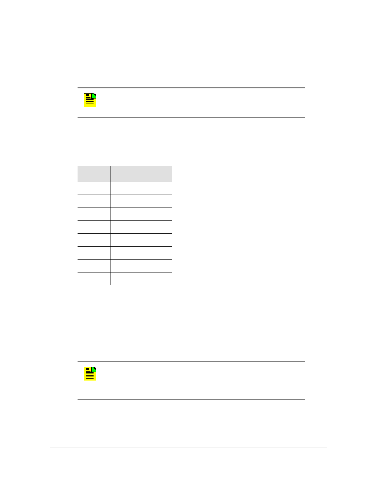
Figure 1-1 is a front view of the TimeProvider 5000 showing connectors and LEDs.
Connections for the GPS/GNSS input signal, Ethernet Management, and EIA-232
serial connection are located on the IMC module. Small Form-factor Pluggable
(SFP) connectors are located on the IOC modules. UTI, E1, T1, 1PPS+TOD, or 10
MHz/1pps, and I/O ports are located on the I/O module. The 1PPS/10MHz ports are
optional. Customers can order units with either
two E1 I/O ports and two E1 Outputs
two E1 I/O ports and 10MHz and 1PPS ports.
two T1 I/O ports and 10MHz and 1PPS ports
two E1 I/O ports and two 1PPS+TOD input ports
Figure 1-1. TimeProvider 5000 Connectors and LEDs
TimeProvider 5000 Connections
Chapter 1 Overview
Figure 1-2. TimeProvider 5000 - Expansion Version Connectors and LEDs
098-00028-000 Revision F – May, 2012 TimeProvider 5000 User’s Guide 33
Page 34

Chapter 1 Overview
TimeProvider 5000 Connections
UTI Input and Output Connections
UTI ports are available in the 090-50311-01, 090-50312-01, and 090-50314-01 I/O
modules. The UTI ports use standard DTI pin-outs, as shown in Table 1-2.
These ports can be used to connect to expansion shelves, TimeProvider E10 or
E30, with a custom cable. This custom cable should be built with twisted-pair cable,
CAT5 or better, with RJ-45 connectors and the pinouts in Table 1-3.
Note: The 090-50315-01 I/O card has a diffe rent pin assignmen t and
uses a standard twisted-pair RJ45 CAT5 cable. A custom cable
should not be used with the 090-50315-01 I/O card.
Table 1-2. UTI Connector Pin Assignments
Pin Signal
1DTI+ DTI
2DTI DTI
3 No connection
4 No connection
5 No connection
6 No connection
7 No connection
8 No connection
Table 1-3. Custom Cable RJ-45 Wiring Connectio ns: UTI Port to Expansion Shelf EXP Port
UTI Port on I/O Card
Mating Connector
Pins
1DTI+ 7
Signal
Comment
EXP Port on Expansion Shelf
Mating Connector
Pins
2DTI 8
34 TimeProvider 5000 User’s Guide 098-00028-000 Revision F – May, 2012
Page 35

TimeProvider 5000 Connections
Chapter 1 Overview
Communications Connections
The IMC allows user control of the TimeProvider 5000 through either the Ethernet
Management port or the EIA-232 serial port.
Ethernet Management Port
The Ethernet Management port on the IMC is standard 10/100Base-T shielded
RJ-45 receptacle. To connect the TimeProvider 5000 to an Ethernet network, use a
standard twisted-pair Ethernet RJ-45 cable (CAT5 minimum).
Expansion Management Port
The expansion Management port on the IMC is a standard 10/100Base-T shielded
RJ-45 receptacle. To connect the TimeProvider 5000 to a TP E10 or TPE30
expansion shelf, use a standard twisted-pair Ethernet RJ-45 cable (CAT5
minimum).
The connector pinouts for the expansion Management port, and all expa nsion ports,
are listed in Table 1-4.
Table 1-4. Expansion RJ-45 Connector Pin Assignments
Pin Signal
1RX+
(Receive positive)
2RX
(Receive negative)
3TX+
(Transmit positive)
4 Reserved
5 Reserved
6TX
(Transmit negative)
7DTI+DTI
8DTI DTI
Ethernet (10/100Base-T)
Ethernet (10/100Base-T)
Ethernet (10/100Base-T)
Ethernet (10/100Base-T)
Comment
098-00028-000 Revision F – May, 2012 TimeProvider 5000 User’s Guide 35
Page 36

Chapter 1 Overview
TimeProvider 5000 Connections
Figure 1-3. IMC Module: Versions -01 through -05
EIA-232 Serial (Craft) Port
The EIA-232 serial port connection is made through a EIA-23 female connector on
the IMC. This port allow you to connect to a terminal or computer using a terminal
emulation software package. When connecting to this port, use a shielded EIA-232
direct connect cable.
36 TimeProvider 5000 User’s Guide 098-00028-000 Revision F – May, 2012
Page 37

TimeProvider 5000 Connections
Chapter 1 Overview
Figure 1-4 shows the EIA-232 male connector pin assignments for the serial port.
Figure 1-4. Serial Port Male Connector Pins
Table 1-5 describes the EIA-232 connector pin assignments for the serial port.
Table 1-5. Serial Port Connector Pin Assignments
Signal Pin
TXD (Received Data) 2
RXD (Transmitted Data) 3
Ground 5
Output Connections
Programmable E1 Output Connections
Two of the traditiona l telecom synchronization coaxial ports (Port1 and Port2) on the
090-5031 1-01, 090-50312-01, and 090-50315-01 versions of the I/O mod ule (Figure
1-5) are software configurable as E1 output ports, with the following signal types:
2.048 Mb/s (G.703/9)
2.048 MHz (G.703/13)
These ports can also be software configured as E1 inputs.
E1 Output Connections
Two of the four traditional telecom synchronization mini-BNC ports (Port3 and
Port4) on the 090-50311-01 version of the I/O module (Figure 1-5) are dedicated E1
output ports, with the following signal types:
2.048 Mb/s (G.703/9)
2.048 MHz (G.703/13)
Programmable T1 Output Connections
Two of the RJ-48C ports (I/O-1 and I/O-2) on the 090-50314-01 version of the I/O
module (Figure 1-6) are software configurable as T1 output ports, with the following
signal types:
098-00028-000 Revision F – May, 2012 TimeProvider 5000 User’s Guide 37
Page 38
Chapter 1 Overview
TimeProvider 5000 Connections
1.544 Mb/s (G.703)
1.544 MHz (G.703)
These ports can also be software configured as T1 outputs .
Note: The T1 ports on the 090-50314-01 version of the I/O
module
which meet the G.703 mask for impedance of 120 ohms, balanced.
Table 1-6 shows the pin assignments for the RJ-48C connectors for the
programmable T1 input/output ports.
Table 1-6. T1 Input/Output Port Pin-Outs - RJ48C Connector
Pin Signal
1Rx Ring
2Rx Tip
can also be configured as E1 and 2048 kHz inputs or output s
3NC
4Tx Ring
5Tx Tip
6NC
7NC
8NC
10MHz & 1PPS Output Connections
Two of the four mini-BNC ports (Port3 and Port4) on the 090-50312-01 version of
the I/O module are 1PPS and 10MHz output ports. See Figure 1-5.
Port3 and Port4 on the 090-50314-01 version of the I/O module are also 1PPS and
10MHz dedicated output ports. See Figure 1-6.
Note: Units that provide 1PPS and 10MHz outputs must be
ordered from the factory; they cannot be reconfigured in the
field. One port provides 1PPS output and one port provides
10 MHz output.
38 TimeProvider 5000 User’s Guide 098-00028-000 Revision F – May, 2012
Page 39

TimeProvider 5000 Connections
Chapter 1 Overview
Expansion Output Connections
The expansion output ports (EXP-1 and EXP-2) on the expansion version of the I/O
module (Figure 1-6) are standard 10/100Base-T shielded RJ-45 receptacles. To
connect the EXP ports of the I/O module to an expansion shelf (TP E10 or TP E30),
use a standard twisted-pair RJ-45 cable (CAT5 minimum). To connect the UTI ports
(UTI-1 and UTI-2) of the I/O module to an expansion shelf, use a custom
twisted-pair RJ-45 cable (CAT5 minimum) with the pinouts shown in Table 1-3.
The RJ-45 pin assignments for the UTI/EXP ports are shown in Table 2-6 and Table
2-7.
Figure 1-5. E1 Versions of I/O Module
Figure 1-6. T1 and Expansion Versions of I/O Module
098-00028-000 Revision F – May, 2012 TimeProvider 5000 User’s Guide 39
Page 40
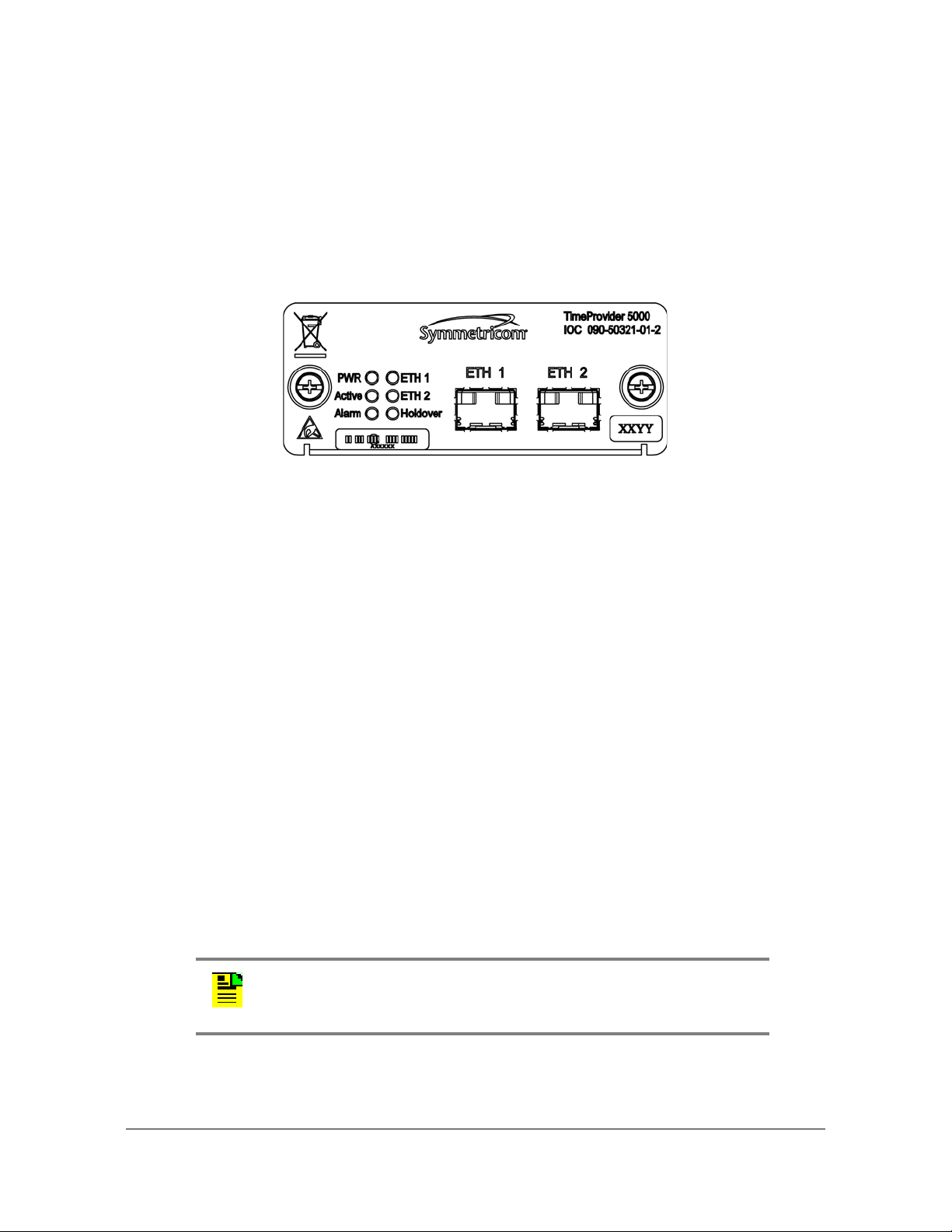
Chapter 1 Overview
TimeProvider 5000 Connections
PTP / NTP Output Connections
The TimeProvider 5000 provides two Ethernet 100/1000 Small-form Factor
Pluggable (SFP) connections on each IOC (see Figure 1-5) module. In PTP (IEEE
1588v2) grand-master mode, the TimeProvider 5000 supports many slaves per
system in unicast mode, multicast mode, or multicast-hybrid mode. In NTP server
mode, the TimeProvider 5000 supports 20,000 transactions/second (120,000
transactions/second with high-capacity NTP option).
Figure 1-7. PTP Output Connections
Input Connections
E1 Input Connections
Mini-BNC ports 1 and 2 on the 090-50311-01, 090-50312-01, and 090-50315-01
versions of the I/O module (see Figure 1-5) are software configurable as traditional
telecom input ports with the following signal types:
2.048 Mb/s (G.703/9)
2.048 MHz (G.703/13)
These ports can also be software configured as E1 outputs.
T1 Input Connections
Two of the RJ-45 ports (I/O-1 and I/O-2) on the 090-50314-01 version of the I/O
module (Figure 1-6) are software configurable as traditional T1 telecom input ports
with the following signal types:
1.544 Mb/s (G.703)
1.544 MHz (G.703)
These ports can also be software configured as T1 outputs.
Note: The T1 ports on the 090-50314-01 version of the I/O
module
which meet the G.703 mask for impedance of 120 ohms, balanced.
can also be configured as E1 and 2048 kHz inputs or output s
40 TimeProvider 5000 User’s Guide 098-00028-000 Revision F – May, 2012
Page 41

TimeProvider 5000 Connections
Chapter 1 Overview
1PPS+TOD Input Connections
Two of the RJ-45 ports (1PPS+TOD-1 and 1PPS+TOD-2) on the 090-50315-01
expansion version of the I/O module (Figure 1-6) are input ports for 1PPS and TOD
information transmitted at RS-422 level. See Table 1-7 for pin-outs for the
1PPS+TOD connectors.
GNSS Connection
The IMC (versions 090-50331-04 and 090-50331-05) has an SMA connector for
input from GPS (090-50331-05) and Beidou/GPS (090-50331-04) navigation
satellites to provide a frequency and time reference (see Figure 1-3). This port
supports input from both GPS and Beidou satellites for the 090-50331-04 version of
the IMC and input from GPS satellites for the 090-50331-05 version.
GPS Connection
The IMC (versions 090-50331-01, 090-50331-02, 090-50331-04, and
090-50331-05) has an SMA connector for GPS input to provide a frequency and
time reference (see Figure 1-3).
Table 1-7. 1PPS+TOD Port Pin-Outs - RJ45 Connector
Pin Signal Comment
1 No Connection Default state is open (high impedance)
2 No Connection Default state is open (high impedance)
3 422_1_N 1PPS
4 GND RS422 GND
5 GND RS422 GND
6 422_1_P 1PPS
7 422_2_N TOD time information
8 422_2_P TOD time information
098-00028-000 Revision F – May, 2012 TimeProvider 5000 User’s Guide 41
Page 42

Chapter 1 Overview
TimeProvider 5000 Connections
Power and Ground Connections
The TimeProvider 5000 uses –48 VDC power and is not equipped with a Power
switch; DC power is controlled by a power distribution panel connected to the power
connectors. Frame ground connections on the TP 5000 are made on the grounding
stud located on the left side of the front panel, as identified with the international
Ground marking, as shown in Figure 1-8. Frame ground connections on the TP E10
and TP E30 expansion shelves are made on the grounding stud located on the righ t
side of the front panel (see Figure 1-9 and Figure 1-10).
Warning: To avoid serious personal injury or death, exercise caution
when working near high voltage lines and follow local building
electrical codes for grounding the chassis.
Figure 1-8. TimeProvider 5000 Power and Ground
Figure 1-9. TimeProvider E10 Power amd Ground
Figure 1-10. TimeProvider E30 Power and Ground
42 TimeProvider 5000 User’s Guide 098-00028-000 Revision F – May, 2012
Page 43

Physical Description
The TimeProvider 5000 consists of a 19-inch (48 cm) rack mount chassis, plug-in
modules, and hardware. The TP E10 and TP E30 each consist of a 19-inch (48 cm)
rack mount chassis and hardware.
Note: The TP 5000, TP E10, and TP E30 comes equipped with
19-inch rack mounting brackets. 23-inch (58.42 cm) rack mounting
adapters are also available as a separately ordered item. 21-inch
(ETSI) rack mounting adapters are available as a separately ordered
item.
The TimeProvider 5000 has one I/O module slot, two IOC module slots, and one
IMC module slot. The grounding lug is located near the I/O module and the power
supply connectors are located on both sides of the chassis (see Figure 1-11). The
minimum configuration is an I/O module, an IOC module, and an IMC module. The
second IOC module slot is available for redundancy. See TimeProvider 5000 Part
Numbers, on page 398.
Chapter 1 Overview
Physical Description
The TimeProvider E10 SyncE/PTP expansion shelf has one block of RJ-45
expansion connectors (2 Input ports, 2 Output ports), two blocks of Gigabit SFP
connectors (16 ports). The shelf also has six LEDs located on the left side of the
front panel. The shelf features a recessed rotary switch with 10 positions that is
used to set the shelf ID and a recessed reset switch. The grounding lug is located
on the right side of the front panel. The power supply connectors are located on
both sides of the chassis (see Figure 1-12).
The TimeProvider E30 E1/1PPS+TOD expansion shelf has one block of RJ-45
expansion Input/Output connectors (2 Input ports, 2 Output ports), two blocks of
SMB output connectors (12 ports), and three blocks of RJ-45 output connectors (12
ports). The shelf also has six LEDs located on the left side of the front panel. The
grounding lug is located on the right side of the front panel. The power supply
connectors are located on both sides of the chassis (see Figure 1-13).
098-00028-000 Revision F – May, 2012 TimeProvider 5000 User’s Guide 43
Page 44

Chapter 1 Overview
Physical Description
Figure 1-11. TimeProvider 5000 Modules and Power Connections
Figure 1-12. TimeProvider E10 Expansion Shelf Connections
Figure 1-13. TimeProvider E30 Expansion Shelf Connections
44 TimeProvider 5000 User’s Guide 098-00028-000 Revision F – May, 2012
Page 45
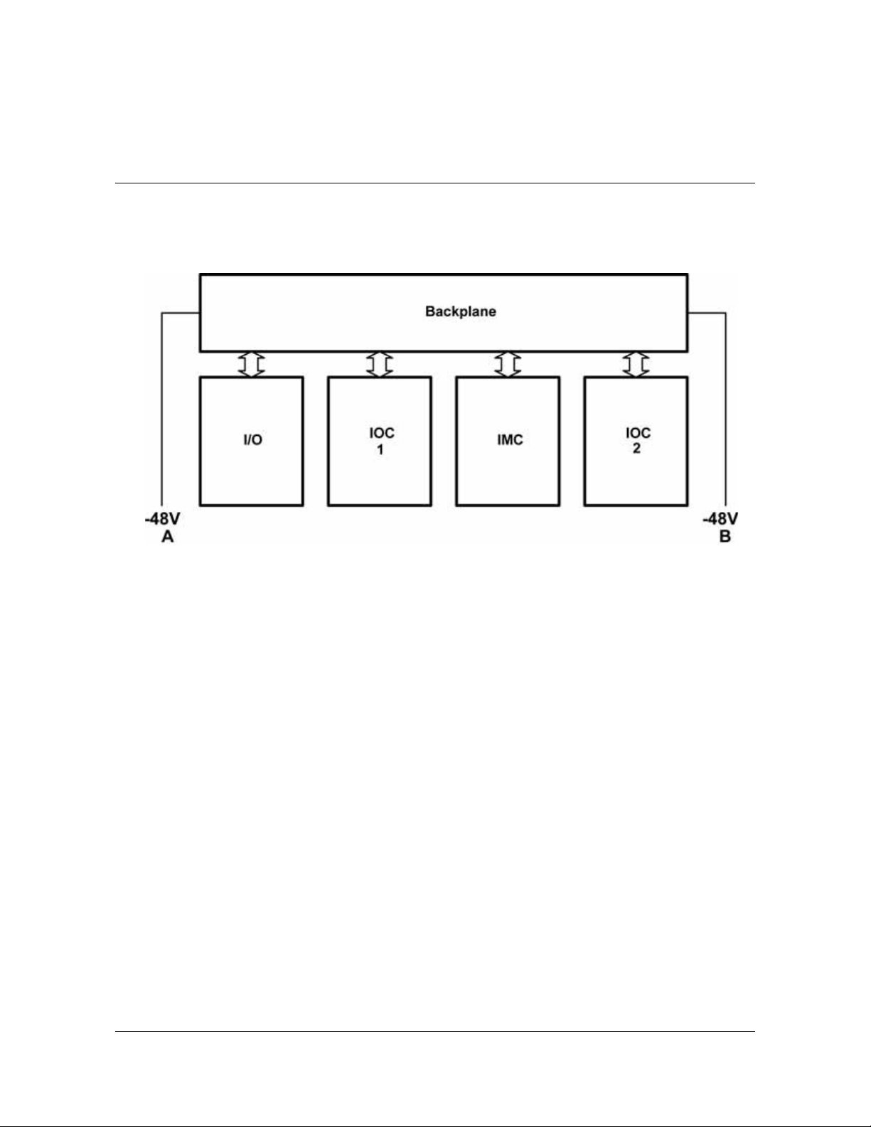
Functional Description
See Figure 1-14 below for a block diagram of the TimeProvider 5000.
Figure 1-14. TimeProvider 5000 Block Diagram
Chapter 1 Overview
Functional Description
TimeProvider 5000 Expansion Shelf System
The TimeProvider 5000 expansion shelf system consists of a TP5000 with
expansion versions of the IMC and I/O cards, a new TimeProvider E10 output
expansion shelf with Gigabit SyncE/PTP ports, and a new TimeProvider E30 output
expansion shelf with E1 and 1PPS+TOD ports.
The TP 5000 expansion shelf system supports two IOC cards in 1+1 redundant
configuration. These two IOC cards track one or more of the time and frequency
reference inputs and provide the stable time and fre quency signals that are used to
generate output synchronization signals. The 090-50331-04 version of the IMC
supports the Beidou satellite system. The 090-50301-02 chassis, 090-5031 5-01 I/O
module and the 090-50331-02, 090-50331-04, and 090-50331-05 versions of the
IMC will support 1PPS+TOD inputs. The 090-50331-02, 090-50331-04, and
090-50331-05 versions of the IMC support the expansion shelves.
Functionally the TimeProvider 5000 system can be thought of as a BITS or SSU in a
central office or a secondary office. It accepts time and frequency reference inputs
in multiple formats, and it provides time and frequency synchronization signals to
the network equipment in the office.
Figure 1-16 shows the physical interfaces of a typical TimeProvider 5000 expansion
shelf system that consists of a TP5000 and two output expansion shelves.
098-00028-000 Revision F – May, 2012 TimeProvider 5000 User’s Guide 45
Page 46

Chapter 1 Overview
Functional Description
The TP5000 has four primary functions in the system:
Input shelf for the system
Timing synchronization source to expansion shelves using DTI
External management interface
Controller for the expansion shelves in the system.
In the TimeProvider 5000 expansion shelf system, expansion shelves are primarily
output shelves. They use the time and frequency information from the TP5000 and
convert them to different synchronization signal formats. Symmetricom offers two
types of expansion shelves for the TP5000: the TimeProvider E30 expansion shelf
provides E1 and 1PPS+TOD outputs and the TimeProvider E10 expansion shelf
provides PTP and SyncE outputs. More outputs can be added by adding
appropriate expansion shelves.
Expansion Connections
The TP 5000 provides time and frequency to the expansion shelves through DTI
links in the expansion interface. The TP5000 controls and manages the expansion
shelves through Ethernet in the expansion interface. The Ethernet management link
and the DTI links share the same physical RJ-45 connector but they are logically
two separate networks.
Figure 1-15. Expansion Connector on Expansion Shelf
Figure 1-15 shows the Expansion connector on the expansion shelves. Figure 1- 18
is a block diagram of the TimeProvider E30 E1/1PPS+TOD exp ansion shelf. Figure
1-17 is a block diagram of the TimeProvider E10 SyncE/PTP expansion shelf.
46 TimeProvider 5000 User’s Guide 098-00028-000 Revision F – May, 2012
Page 47

Figure 1-16. Physical Interfaces of TP 5000 with Two Expansion Shelves
Chapter 1 Overview
Functional Description
Figure 1-17. TimeProvider E10 SyncE/PTP Expansion Shelf Block Diagram
098-00028-000 Revision F – May, 2012 TimeProvider 5000 User’s Guide 47
Page 48

Chapter 1 Overview
Functional Description
Figure 1-18. TimeProvider E30 E1/1PPS+TOD Expansion Shelf Block Diagram
The following actions must be performed to support the use of expansion shelves
with the TP 5000.
Enable ETH on TP 5000 IMC module’s DTI / ETH connector to allow
communication with the expansion shelves
Set a unique ID (0-9) for each expansion shelf using the rotary switch o n its front
panel
Enable DTI
– TP 5000 - IMC
– TP 5000 - I/O
– Expansion shelf
Provision output signals for each expansion shelf
Enable state(s) of output(s)
The following actions must be performed to support the use of expansion shelves
with the TP 5000.
Enable ETH on TP 5000 IMC module’s DTI / ETH connector to allow
communication with the expansion shelves
Set a unique ID (0-9) for each expansion shelf using the rotary switch o n its front
panel
Enable DTI
48 TimeProvider 5000 User’s Guide 098-00028-000 Revision F – May, 2012
Page 49

Chapter 1 Overview
Functional Description
– TP 5000 - IMC
– TP 5000 - I/O
– Expansion shelf
Provision output signals for each expansion shelf
Enable state(s) of output(s)
Figure 1-19 is a diagram of the expansion connections for a TP 5000 with one
expansion shelf. Figure 1-20 is a diagram of the expansion connections for a TP
5000 with 5 expansion shelves.
Note: If using UTI ports from I/O modue 090-50311-01,
090-50312-01, or 090-50314-01, a custom cable must be used
between the I/O module and the expansion shelf. See
details.
Table 2-9 for
Figure 1-19. Expansion Connections for TP 5000 with a Single Expansion Shelf
098-00028-000 Revision F – May, 2012 TimeProvider 5000 User’s Guide 49
Page 50

Chapter 1 Overview
Functional Description
Figure 1-20. Expansion Connections for TP 5000 with 5 Expansion Shelves
50 TimeProvider 5000 User’s Guide 098-00028-000 Revision F – May, 2012
Page 51

Chapter 1 Overview
Functional Description
IMC Module LEDs
The IMC module provides connectors for 10/100 Ethernet management, EIA-232
serial management, and the GPS/GNSS Timing Antenna. The IMC’s LEDs indicate
the following:
Power Module Status
Battery A & B Status
System Health Status
Alarm Status
GPS/GNSS Signal Status
IOC Module LEDs
The IOC module also has two PTP Grand Master 100/1000 Ethernet SFP port s with
LEDs that indicate link and link speed. The IOC module has LED status indicators
and test outputs for the system. The LEDs indicate:
Power Status
Active Status
Ethernet Status
Alarm Status
Holdover Status
Expansion Shelf LEDs
The TP E10 expansion shelf has sixteen (16) 100/1000 Ethernet SFP ports with
LEDs that indicate link and link speed.The TP E30 has twelve (12) 1PPS ports with
LEDs that indicate port enable state. The TP E10 and TP E30 also each have LED
status indicators. The LEDs indicate:
Power Status
Active Status
Ethernet Status
Alarm Status
Holdover Status
098-00028-000 Revision F – May, 2012 TimeProvider 5000 User’s Guide 51
Page 52

Chapter 1 Overview
Functional Description
Communication Ports
Communications ports on the IMC allow you to provision, monitor, and troubleshoot
the chassis. You can communicate with the TimeProvider 5000 using either CLI or
SNMP protocols.
Local Craft Serial Port
The EIA-232 port supports local control; you can configure the TimeProvider 5000
with CLI commands using a terminal or computer with terminal emulation software.
The connector is located on the IMC module. The Local port is configured as a DCE
interface and the default settings are as follows:
Baud = 57.6K
Data Bits = 8 bits
Note: The SNMP feature can either be ordered in a new system, or
added to a previously ordered system as a field upgrade (see Table
6-7 for part number). Contact your Symmetricom representative for
more information.
Parity = 0
Stop bits = 1
Flow Control, None
Management Ethernet Port
The Management Ethernet connector provides connectivity to an Ethernet local
area network. Each Ethernet port has a unique internet protocol (IP) address and
once the IP address is set and a connection is made to a LAN, you can access the
TimeProvider 5000.
Synchronization and Timing Inputs
The TimeProvider 5000 can use either GPS, Beidou, E1, T1, or 1PPS+T OD signals
as external input references. The GPS and GPS/Beidou references connect to SMA
connectors on the IMC card. The GPS/Beidou port is labeled "GNSS". The E1 and
T1 inputs are configurable ports located on the I/O module. The 1PPS+TOD input
ports are located on the 090-50315-01 version of the I/O module.
Synchronization and Timing Outputs
The TimeProvider 5000 has four GbE timing output s (2 per IOC card), which can be
configured as either Precision Timing Protocol (PTP) or Network Timing Protocol
(NTP) outputs. The expansion version of the I/O card, 090-50315-01, also features
two DTI timing outputs that are used to provide timing to expansion shelves.
52 TimeProvider 5000 User’s Guide 098-00028-000 Revision F – May, 2012
Page 53

Chapter 1 Overview
Functional Description
System Inputs and Outputs
Programmable Input/Output Ports
The TimeProvider 5000 has two mini-BNC ports on the 090-50311-01 and
090-50312-01 versions of the I/O module, and two SMB ports on the 090-50315-01
version, that are software configurable as either E1 input or output ports. They can
provide or receive the following signal types:
2.048 Mb/s (G.703/9)
2.048 MHz (G.703/13)
The 090-50314-01 version of the I/O module has two RJ-45 ports that are software
configurable as either T1 input or output ports. They can provide or receive the
following signal types:
1.544 Mb/s (G.703)
1.544 MHz (G.703)
The 090-50315-01 version of the I/O module has two RJ-45 input ports for 1PPS
and TOD information transmitted at RS-422 level
Dedicated Output Ports
The 090-50311-01 version of the I/O module (Figure 1-5) also has two mini-BNC
ports that are dedicated E1 output ports with the following signal types:
2.048 Mb/s (G.703/9)
2.048 MHz (G.703/13)
The 090-50312-01 (see Figure 1-5) and 090-50314-01 (see Figure 1-6) versions of
the I/O module also have two mini-BNC ports that are dedicated output ports with
the following signal types:
1PPS
10 MHz
Note: Units that provide 1PPS/10MHz output must be
configured at the factory when ordered; they cannot be
reconfigured in the field. One port provides 1PPS output and
one port provides 10MHz output.
098-00028-000 Revision F – May, 2012 TimeProvider 5000 User’s Guide 53
Page 54

Chapter 1 Overview
Functional Description
TP E10 Expansion Shelf System Outputs
PTP/SyncE Output Ports
The TP E10 expansion shelf features 16 output ports with SyncE/PTP signals.
1PPS Output Port
The TP E10 expansion shelf includes one 1PPS SMB female output port.
TP E30 Expansion Shelf System Outputs
E1 Output Ports
The TP E30 expansion shelf features 12 dedicated E1 output ports with the
following signal types:
2.048 Mb/s (G.703/9)
2.048 MHz (G.703/13)
1PPS+TOD Output Ports
The TP E30 expansion shelf features 12 1PPS+TOD output ports. 1PPS and TOD
information is transmitted at RS-422 level.
Expansion Shelf ID Switch
Each expansion shelf must have a unique user-defined shelf ID. There can be up to
10 shelf IDs (0 to 9) in the system. The user can set the shelf ID using a mechanical
rotary switch on the front panel.
Figure 1-21. Shelf ID Selector
54 TimeProvider 5000 User’s Guide 098-00028-000 Revision F – May, 2012
Page 55

Configuration Management
The Command Line Interface (CLI), also called the ASCII command set, can be
used to control the TimeProvider 5000 from a terminal connected to the EIA-232
serial port, or the Ethernet port. Refer to Chapter 3, CLI Commands and SNMP for
further details.
Note: Before you can communicate with the TimeProvider 5000
through an Ethernet connection, you must first configure the Ethernet
port using the serial connection (see Provisioning the Ethernet Ports,
on page 280).
Alarms
The TP5000 uses alarms to notify you when certain conditions are deteriorating
below specified levels. Expansion shelf alarms are reported to the TP 5000 that
controls the shelf. These alarms are indicated by module status LEDs and by SNMP
traps. You can provision the alarm to either be enabled or disabled and the current
alarm state can be obtained via th e communication ports. For more information, see
Provisioning Alarms, on page 346 and Appendix A, System Messages.
Chapter 1 Overview
Configuration Management
098-00028-000 Revision F – May, 2012 TimeProvider 5000 User’s Guide 55
Page 56

Chapter 1 Overview
Alarms
56 TimeProvider 5000 User’s Guide 098-00028-000 Revision F – May, 2012
Page 57

Chapter 2 Installing
This chapter describes the procedures for installing the TimeProvider 5000, as well
as the TimeProvider E10 and TimeProvider E30 expansion shelves.
In This Chapter
Getting Started
Unpacking the Unit
Rack Mounting the Chassis
– Rack Mounting the TimeProvider 5000 Main Shelf
– Rack Mounting the TP E10 & TP E30 Expansion Shelves
Working With Modules
Signal Connections
– Communications Connections
– TP 5000 Synchronization and Timing Connections
– TimeProvider E10 Synchronization and Timing Connections
– TimeProvider E30 Synchronization and Timing Connections
Connecting the GPS/GNSS Antenna
Making Ground and Power Connections
Installation Check List
Applying Power to the TimeProvider 5000
098-00028-000 Revision F – May, 2012 TimeProvider 5000 User’s Guide 57
Page 58

Chapter 2 Installing
Getting Started
Getting Started
Before you begin to install the TimeProvider 5000, TimeProvider E10 or
TimeProvider E30, review the information in this section.
If you encounter any difficulties during the installation process, contact
Symmetricom Global Services (SGS). See Contacting Technical Support, on page
405 for telephone numbers. Contact SGS - Product Technical Support for technical
information. Contact Customer Service for information about your order, RMAs, and
other information.
Security Considerations for TP5000 Installation
The TP 5000, TP E10 and TP E30 should be installed in a physically secure
location.
The TP 5000's IMC Module's Ethernet port should be installed behind the
company's firewall to prevent public access.
Whenever possible, the TP 5000's Ethernet service ports should be installed
behind the company's firewall to prevent public access.
Site Survey
Before you begin installation, determine the chassis location, ensure the
appropriate power source is available (–48 VDC), and ensure that the equipment
rack is properly grounded.
The TimeProvider 5000 is designed to mount in a 19-inch (48 cm) rack, occupies
1.75 in (4.5 cm, 1 RU) of vertical rack space, and has a depth of 18 in (45.7 cm).
The TimeProvider E10 and TimeProvider E30 expansion shelves are also designed
to mount in a 19-inch (48 cm) rack, and each occupies 1.75 in (4.5 cm, 1 RU) of
vertical rack space, and has a depth of 10 in (25.4 cm). .
Note: 1RU above the TimeProvider 5000 must be left
unoccupied for heat dissipation
Note: 23-inch (58.42 cm) rack mounting adapters are also available
as a separately ordered item. 21-inch (ETSI) rack mounting adapters
are available as a separately ordered item.
The TimeProvider 5000 is to be installed into a rack with permanent connection to
the -48VDC mains. This connection is to be made to a branch over-current,
short-circuit protection device with replaceable fusing of 5 amps, maximum. For
permanently connected equipment a readily accessible disconnect device shall be
incorporated in the building installation wiring.
58 TimeProvider 5000 User’s Guide 098-00028-000 Revision F – May, 2012
Page 59

Chapter 2 Installing
Getting Started
The TimeProvider E10 expansion shelf is to be inst a lled into a rack with permanent
connection to the -48VDC mains. This connection is to be made to a branch
over-current, short-circuit protection device with replaceable fusing of 2 amps,
maximum. For permanently connected equipment a readily accessible disconnect
device shall be incorporated in the building installation wiring.
The TimeProvider E30 expansion shelf is to be inst a lled into a rack with permanent
connection to the -48VDC mains. This connection is to be made to a branch
over-current, short-circuit protection device with replaceable fusing of 1 amp,
maximum. For permanently connected equipment a readily accessible disconnect
device shall be incorporated in the building installation wiring.
Environmental Requirements
To prevent the unit from malfunctioning or interfering with other equipment, install
and operate the unit according to the following guidelines:
Operating temperature: 23Fto 113F (–5 C to 45C) for TP 5000
23Fto 131F (–5 C to 55C) for TP E10 and TP E30
Operating Humidity:90% to 100% RH, maximum, w/condensation
Use only shielded cable for all signal wiring, including I/O, clocks and Ethernet.
Ground appropriately at both ends, or as required by local standards.
Secure all cable screws to their corresponding connectors.
Caution: To avoid interference, you must consider the
electromagnetic compatibility (EMC) of nearby equipment when you
install the TP 5000, TP E10 and TP E30.
Electromagnetic interference can adversely affect the operation of
nearby equipment.
Installation Tools and Equipment
You will need the following tools and equipment to install the TimeProvider 5000:
Standard tool kit
Cable ties, waxed string or acceptable cable clamps
1 mm² / 18 AWG (minimum) stranded wire at 300 volt insulation for –48 VDC
1 mm² / 16 AWG wire to connect grounding lug to permanent earth ground
Two U.L listed Ring Lugs for grounding connections
Crimping tool to crimp the ring lug
098-00028-000 Revision F – May, 2012 TimeProvider 5000 User’s Guide 59
Page 60

Chapter 2 Installing
Unpacking the Unit
Shielded cabling of the appropriate impedance required by the specific signal
type for signal wiring (including GPS, and Ethernet)
Mating connectors for terminating signal wiring
ESD wrist strap for installing modules
Fasteners for mounting the equipment in rack
Digital multimeter or standard Voltmeter for verifying power connections to the
chassis
Laptop computer with communications software (e.g., Microsoft Hyperterminal,
ProComm Plus or EmTec ZOC) for setting system parameters
Unpacking the Unit
The TimeProvider 5000, TimeProvider E10 and TimeProvider E30 are packaged to
protect them from normal shock, vibration and handling damage.(Each unit is
packaged separately.)
Caution: To avoid electrostatic discharge (ESD) damage to parts that
are packaged with the TP 5000, TP E10 and TP E30, observe the
following procedures.
Unpack and inspect the unit as follows:
1. Wear a properly grounded protective wrist strap or other ESD device.
2. Inspect the container for signs of damage. If the container appears to be
damaged, notify both the carrier and your Symmetricom distributor. Retain the
shipping container and packing material for the carrier to inspect.
3. Open the container, being careful to cut only the packaging tape.
4. Locate and set aside the CD, printed information, and paperwork that is included
in the container.
5. Remove the unit from the container and place it on an anti-static surface.
6. Locate and set aside small parts which may be packed in the container.
7. Remove the accessories from the container.
8. Remove the anti-static packaging from the unit and accessories.
9. Verify that t he model and item number shown on the shipping list agrees with the
model and item number on the equipment. The item number can be found on a
label affixed to the top of the unit, front and center. See Figure 2-1 for the location
of the label on the TP 5000. See Figure 2-2 for the location of the label on the TP
60 TimeProvider 5000 User’s Guide 098-00028-000 Revision F – May, 2012
Page 61

Chapter 2 Installing
Unpacking the Unit
E10. See Figure 2-3 for the location of the label on the TP E30. Contact your
Symmetricom distributor if the model or item number do not match.
For a complete listing of item numbers, see Table 6-7 and Table 6-8.
Figure 2-1. TP 5000 - Location of Product Label
Figure 2-2. TP E10 - Location of Product Label
Figure 2-3. TP E30 - Location of Product Label
098-00028-000 Revision F – May, 2012 TimeProvider 5000 User’s Guide 61
Page 62

Chapter 2 Installing
Rack Mounting the Chassis
Rack Mounting the Chassis
The installation procedure described in this section provides general guidelines for
installing the TimeProvider 50 00, as well as theT imeProvider E10 and TimeProvider
E30 expansion shelves. Always follow applicable local electrical standards.
Rack Mounting the TimeProvider 5000 Main Shelf
Use the following steps to mount the TimeProvider 5000 in a rack.
Note: 1RU above the TimeProvider 5000 must be left
unoccupied for heat dissipation.
Note: The TimeProvider 5000 comes equipped with 19-inch rack
mounting brackets. 23-inch (58.42 cm) rack mounting adapters are
also available as a separately ordered item. 21-inch (ETSI) rack
mounting adapters are available as a separately ordered item.
1. TimeProvider 5000 is shipped with rack mounting brackets attached. The rack
mounting brackets can be removed and reattached in a different orientation, if
desired. See Figure 2-4 for mounting hole placements. See Figure 2-5 and
Figure 2-6 for chassis dimensions. Ensure that the
mounting brackets on both
sides are attached to the chassis at equal distances fr om the front of the unit (see
Figure 2-7) using 6-32 x 1/4-inch screws.
2. Mount the chassis to the front of the equipment rack rails with four screws and
associated hardware. Use the proper screws for the equipment rack.
62 TimeProvider 5000 User’s Guide 098-00028-000 Revision F – May, 2012
Page 63

Figure 2-4. TP 5000 Mounting Hole Placements
Chapter 2 Installing
Rack Mounting the Chassis
Figure 2-5. TP 5000 Chassis Dimensions
Figure 2-6. TP 5000 Chassis Dimensions
Front View
Top View
098-00028-000 Revision F – May, 2012 TimeProvider 5000 User’s Guide 63
Page 64

Chapter 2 Installing
Rack Mounting the Chassis
Figure 2-7. Rack Mounting the TimeProvider 5000
Rack Mounting the TP E10 & TP E30 Expansion Shelves
Use the following steps to mount the TP E10 or TP E30 expansion shelf in a rack.
Note: The TP E10 and TP E30 come equipped with 19-inch rack
mounting brackets. 23-inch (58.42 cm) rack mounting adapters are
also available as a separately ordered item. 21-inch (ETSI) rack
mounting adapters are available as a separately ordered item.
1. The TP E10 and TP E30 are shipped with rack mounting brackets attached. The
rack mounting brackets can be removed and reattached in a different orient ation,
if desired. See Figure 2-8 for mounting hole placements. See Figure 2-9,
Figure 2-10 and Figure 2-11 for chassis dimensions. Ensure that the
brackets
on both sides are attached to the chassis at equal distances from the
front of the unit (see Figure 2-12 for the TP E10, Figure 2-13 for the TP E30)
using 6-32 x 1/4-inch screws.
2. Mount the chassis to the front of the equipment rack rails with four screws and
associated hardware. Use the proper screws for the equipment rack.
mounting
64 TimeProvider 5000 User’s Guide 098-00028-000 Revision F – May, 2012
Page 65

Figure 2-8. TP E10 and TP E30 Mounting Hole Placements - Side View
Figure 2-9. TP E10 Chassis Dimensions - Front View
Chapter 2 Installing
Rack Mounting the Chassis
Figure 2-10. TP E30 Chassis Dimensions - Front View
098-00028-000 Revision F – May, 2012 TimeProvider 5000 User’s Guide 65
Page 66

Chapter 2 Installing
Rack Mounting the Chassis
Figure 2-11. TP E10 and TP E30 Chassis Dimensions - Top View
Figure 2-12. Rack Mounting the TP E10 Expansion Shelf
66 TimeProvider 5000 User’s Guide 098-00028-000 Revision F – May, 2012
Page 67

Figure 2-13. Rack Mounting the TP E30 Expansion Shelf
Chapter 2 Installing
Working With Modules
Working With Modules
This section describes how to install, remove, and handle the modules associated
with the TimeProvider 5000.
Handling Modules
When handling any of the modules, observe the following precautions:
1. Use proper static control precautions when handling modules! Protect the
equipment against ESD (electrostatic discharge) by using a grounded protective
wrist strap and normal equipment grounding.
2. Avoid touching component leads and edge connectors.
3. Avoid placing the module on an ungrounded surface.
4. Avoid allowing the module to come in contact with insulated surfaces.
098-00028-000 Revision F – May, 2012 TimeProvider 5000 User’s Guide 67
Page 68

Chapter 2 Installing
Signal Connections
Inserting Modules
This procedure is common for all modules in the TimeProvider 5000.
Use the following procedure to insert a module into the chassis:
1. Align the module edges within the guides of the selected slot.
2. Slide the module into the chassis and press firmly until it seats fully into its
backplane edge connector.
3. Tighten the captive screws located on each side of the panel.
Caution: All modules can be removed and inserted while system
power is supplied without damaging modules; however, system
performance may be affected.
Note: The I/O card does not have captive screws and requires a
Phillips screwdriver.
Caution: To avoid possible damage or intermittent failures, ensure
that you have completely inserted the module into the chassis and
that you have securely tightened the captive screws.
Removing Modules
To remove a module from the TimeProvider 5000, loosen the screws and then pull
out the module. Be sure to place the module on a static-free surface.
Caution: You must disconnect the antenna (GPS and/or Beidou)
before removing the IMC module.
Signal Connections
The connectors for the GPS and GNSS input signal, Ethernet management,
expansion connections, and EIA-232 serial connection are located on the IMC
module. The PTP output connectors are located on the IOC module. The E1, T1,
1PPS+TOD, 10 MHz, 1PPS, Expansion, and UTI connectors are located on
different versions of the I/O module.
68 TimeProvider 5000 User’s Guide 098-00028-000 Revision F – May, 2012
Page 69

Chapter 2 Installing
Signal Connections
Communications Connections
The IMC allows user control of the TimeProvider 5000. The EIA-232 serial po rt and
Ethernet Management port are located on the IMC as shown in Figure 2-14. See
Working With Modules, on page 67 for module installation instructions.
Figure 2-14. IMC Module Versions -01 through -05
System Management (MGMT) Port
The System Management port is standard 10/100Base-T shielded RJ-45
receptacle. To connect the TimeProvider 5000 to an Ethernet network, use an
Ethernet RJ-45 cable. See Table 2-1 for connector pinouts.
098-00028-000 Revision F – May, 2012 TimeProvider 5000 User’s Guide 69
Page 70

Chapter 2 Installing
Signal Connections
Table 2-1. System Management Ethernet Connector Pin Assignments
TX+ (Transmit positive) 1
TX- (Transmit negative) 2
RX- (Receive negative) 3
RX+ (Receive positive) 6
Not Used 4, 5, 7, 8
Expansion Port
The expansion ports are standard 10/100Base-T shielded RJ-45 receptacles. To
connect the TimeProvider 5000 to an expansion shelf (TP E30 E1/1PPS+TOD or
TP E10 SyncE/PTP, use a standard twisted pair Ethernet RJ-45 cable (CAT5
minimum). The Ethernet management link and the DTI links share the same
physical RJ-45 connector, as shown in Figure 2-14, but they are logically two
separate networks. The expansion port from the IMC must always be used when
using expansion shelves to provide management messages via Ethernet. (The
expansion ports on the I/O card only provide DTI.)
Signal Name Pin
Figure 2-20 shows the expansion connections for a TP 5000 with a single
expansion shelf, with redundant DTI connections from the expansion ports on the
IMC and I/O cards. Figure 2-21 shows the expansion connections for a TP 5000
with five expansion shelves. Redundant DTI connections for the IN1 and IN2 ports
on each expansion shelf are used to protect against various failure scenarios.
The connector pinouts are listed in Table 2-2.
Table 2-2. DTI/Ethernet RJ-45 Connector Pin Assignments
Pin Signal
1RX+
(Receive positive)
2RX
(Receive negative)
3TX+
(Transmit positive)
4 Reserved
5 Reserved
Ethernet (10/100Base-T)
Ethernet (10/100Base-T)
Ethernet (10/100Base-T)
Comment
70 TimeProvider 5000 User’s Guide 098-00028-000 Revision F – May, 2012
Page 71

Table 2-2. DTI/Ethernet RJ-45 Connector Pin Assignments (Continued)
Chapter 2 Installing
Signal Connections
Pin Signal
6TX
(Transmit negative)
7DTI+DTI
8DTI DTI
Ethernet (10/100Base-T)
Comment
EIA-232 Serial (Craft) Port
The EIA-232 serial port connection is made through a EIA-232 fe male connector on
the IMC. This ports allow you to connect to a terminal or computer using a terminal
emulation software package for remote monitoring and con trol. When connecting to
this port, use a shielded EIA-232 direct connect cable.
Figure 2-15 shows the EIA-232 male connector pin assignments for the serial port.
Figure 2-15. Serial Port Male Connector Pins
Table 2-3 describes the EIA-232 connector pin assignments for the serial port.
Table 2-3. Serial Port Connector Pin Assignments
Signal Pin
TXD (Received Data) 2
RXD (Transmitted Data) 3
Ground 5
TP 5000 Synchronization and Timing Connections
The basic version TimeProvider 5000 has one GPS input on the IMC module and
two redundant PTP timing outputs on each IOC module. There are also four
connections on the I/O module, two of which can be outputs or inputs and two
connections that are dedicated outputs. The version of the I/O module determines
the configuration of the I/O connections:
098-00028-000 Revision F – May, 2012 TimeProvider 5000 User’s Guide 71
Page 72

Chapter 2 Installing
Signal Connections
The 090-5031 1-01, 090-50312-01, and 090-50315-01 (see Figure 2-18) versions
of the I/O module have two programmable E1 input/output connections, while the
090-50314-01 (see Figure 2-19) version of the I/O module has two
programmable T1 input/output connections.
The 090-50311-01 version of the I/O module has two dedicated E1 output
connections, while the 090-50312-01 (see Figure 2-18) and 090-50314-01 (see
Figure 2-19) versions of the I/O module have two dedicated output connections,
10MHz and 1PPS.
GPS Connections
To connect a GPS signal, you must install a GPS antenna. See Connecting the
GPS/GNSS Antenna, on page 83. Also see Working With Modules, on page 67 for
module installation instructions.
Caution: The GPS cable should only be connected while the unit is
properly Earth grounded.
GNSS Connections
To connect a GNSS signal, you must install a Beidou or GPS antenna. See
Connecting the GPS/GNSS Antenna, on page 83. Also see Working With Mod ules,
on page 67 for module installation instructions.
Caution: The GNSS cable should only be connected while the unit is
properly Earth grounded.
PTP / NTP Connections
The two Ethernet 100/1000 Small-form Factor Pluggable (SFP) connections on
each IOC provide redundant PTP outputs. See Figure 2-16.
Figure 2-16. PTP Output Connections
72 TimeProvider 5000 User’s Guide 098-00028-000 Revision F – May, 2012
Page 73

Only the SFP transceivers in Table 2-4 are recommended and supported. Other
SFP transceivers are not supported and may cause the TimeProvider 5000 to not
comply with regulatory requirements. Figure 2-17 shows a typical optical SFP
transceiver.
Figure 2-17. Optical SFP Transceiver
Table 2-4. Recommended and Supported SFP Transceivers
Chapter 2 Installing
Signal Connections
Type Transceiver
Optical 1000 Base-LX Single-Mode Ethernet 131 0nm
(Symmetricom 121-20621-10-2)
Optical 1000 Base-SX Multi-Mode Ethernet 850nm
(Symmetricom 121-20621-11-2)
RJ45 100/1000/1GbE Base-T Full-Duplex
(Symmetricom 121-20621-12-2)
Note: Recommended and supported SF P conne cto r s com ply with
FDA radiation performance standards, 21 CFR Subchapter J.
Figure 2-18. Output Connections for E1 Versions of I/O Module
Avago AFCT-5701PZ
Finisar FTLF1319P1BTL
Avago AFBR-5710PZ
Finisar FTLF8519P2BNL
Avago ABCU-5710RZ
098-00028-000 Revision F – May, 2012 TimeProvider 5000 User’s Guide 73
Page 74

Chapter 2 Installing
Signal Connections
Figure 2-19. Output Connections for T1 and Expansion Versions of I/O Module
E1 Connections
Two of the four coaxial ports on the 090-50311-01 and 090-50312-01, and
090-50315-01 versions of the I/O module (see Figure 2-18 and Figure 2-19) are
software configurable as either E1 input or output ports. These ports are mini-BNC
male ports, except for the 090-50315-01, which uses SMB male connectors. They
can provide or receive the following signal types:
2.048 Mb/s (G.703/9)
2.048 MHz (G.703/13)
The 090-50311-01 version of the I/O module (Figure 2-18) also has two mini-BNC
male ports that are dedicated E1 output ports with the following signal types:
2.048 Mb/s (G.703/9)
2.048 MHz (G.703/13)
Note: Amphenol mini-BNC connectors (031-70261) can be
used to create cables. Alternatively, Symmetricom sells a kit of
4 mini-BNC to BNC adapter cables (093-00068-000).
T1 Connections
The 090-50314-01 version of the I/O module has two RJ-45 ports that are software
configurable as either T1 input or output ports (see Figure 2-19). They can provide
or receive the following signal types:
1.544 Mb/s (G.703)
1.544 MHz (G.703)
Note: The T1 ports on the 090-50314-01 version of the I/O
module
can also be configured as E1 and 2048 kHz inputs or output s
which meet the G.703 mask for impedance of 120 ohms, balanced.
74 TimeProvider 5000 User’s Guide 098-00028-000 Revision F – May, 2012
Page 75

Chapter 2 Installing
Signal Connections
Table 2-5. T1 Input/Output Port Pin-Outs - RJ48C Connector
Pin Signal
1Rx Ring
2Rx Tip
3NC
4Tx Ring
5Tx Tip
6NC
7NC
8NC
1PPS & 10MHz Connections
The 090-50312-01 (see Figure 2-18) and 090-50314-01 (see Figure 2-19) versions
of the I/O module also have two mini-BNC male ports that are dedicated output
ports with the following signal types:
1PPS
10 MHz
Note: Units that provide 1PPS/10MHz output must be
configured at the factory when ordered; they cannot be
reconfigured in the field. One port provides 1PPS output and
one port provides 10MHz output.
Expansion Connections
The TP5000 provides timing to the expansion shelves through two DTI links. The
090-50315-01 version of the I/O card features two standard shielded RJ-45
receptacles, labeled EXP-1 and EXP-2, as shown in Figure 2-19. The
090-50311-01, 090-50312-01, 090-50314-01 versions of the I/O card feature two
standard shielded RJ-45 receptacles, labeled UTI-1 and UTI-2, as shown in
Figure 2-18 and Figure 2-19, which are also used for DTI signals. The expansion
shelves use the time and frequency information from the TP5000 and convert them
to different synchronization signal formats.
To connect the expansion (EXP) ports on the 090-50315-01 version of the TP 5000
I/O card to an expansion shelf (TP E10 or TP E30), use a standard twisted pair
Ethernet RJ-45 cable, CAT5 or better. See Table 2-6 for pin-outs for the EXP
expansion RJ-45 connectors on the I/O card.
098-00028-000 Revision F – May, 2012 TimeProvider 5000 User’s Guide 75
Page 76

Chapter 2 Installing
Signal Connections
To connect the expansion (UTI) ports on the 090-50311-01, 090-50312-01, and
090-50314-01 versions of the TP 5000 I/O card to an expansion shelf (TP E10 or
TP E30), use a custom cable. See Table 2-7 for pin-outs for the UTI expansion
RJ-45 connectors on the I/O card. See Table 2-8 for pin-outs for the EXP expansion
RJ-45 connectors on the expansion shelves. The custom cable should be built with
twisted-pair cable, CAT5 or better, with RJ-45 connectors and the custom mating
connector pinouts in Table 2-9.
Figure 2-20 shows the expansion connections for a TP 5000 with a single
expansion shelf, with redundant DTI connections from the expansion ports on the
IMC and I/O cards. Figure 2-21 shows the expansion connections for a TP 5000
with five expansion shelves. Redundant DTI connections for the IN1 and IN2 ports
on each expansion shelf are used to protect against various failure scenarios.
Note: If using UTI ports from I/O modue 090-50311-01,
090-50312-01, or 090-50314-01, a custom cable must be used
between the I/O module and the expansion shelf. See
details.
Table 2-9 for
The expansion port from the IMC must always be used when using expansion
shelves to provide management messages via Ethernet. (The expansion ports on
the I/O card only provide DTI.)
Table 2-6. Expansion Port (EXP) RJ-45 Connector Pin Assignments - I/O Card
Pin Signal
1 No connection
2 No connection
3 No connection
4 No connection
5 No connection
6 No connection
7 DTI+ DTI
8DTI DTI
Comment
76 TimeProvider 5000 User’s Guide 098-00028-000 Revision F – May, 2012
Page 77

Chapter 2 Installing
Signal Connections
.
Table 2-7. UTI Port RJ-45 Connector Pin Assignments - I/O Card
Pin Signal
Comment
1DTI+ DTI
2DTI DTI
3 No connection
4 No connection
5 No connection
6 No connection
7 No connection
8 No connection
.
Table 2-8. EXP Port RJ-45 Connector Pin Assignments - TP E10 & TP E30 Expansion Shelves
Pin Signal
1RX+
Ethernet (10/100Base-T)
Comment
(Receive positive)
2RX
Ethernet (10/100Base-T)
(Receive negative)
3TX+
Ethernet (10/100Base-T)
(Transmit positive)
4 Reserved
5 Reserved
6TX
Ethernet (10/100Base-T)
(Transmit negative)
7DTI+ DTI
8DTI DTI
098-00028-000 Revision F – May, 2012 TimeProvider 5000 User’s Guide 77
Page 78

Chapter 2 Installing
Signal Connections
.
Table 2-9. Custom Cable RJ-45 Wiring Connectio ns: UTI Port to Expansion Shelf EXP Port
UTI Port on I/O Card
Mating Connector
Pins
Signal
EXP Port on Expansion Shelf
Mating Connector
Pins
1DTI+ 7
2DTI 8
Figure 2-20. DTI and DTI/ETH Connection for TP 5000 and One Expansion Shelf
78 TimeProvider 5000 User’s Guide 098-00028-000 Revision F – May, 2012
Page 79
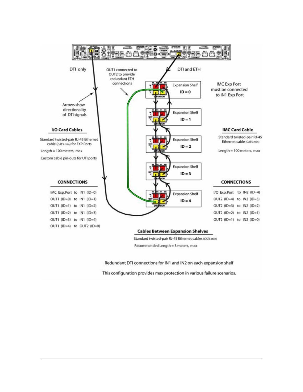
Figure 2-21. DTI and DTI/ETH Connection for TP 5000 and Five Expansion Shelves
Chapter 2 Installing
Signal Connections
098-00028-000 Revision F – May, 2012 TimeProvider 5000 User’s Guide 79
Page 80

Chapter 2 Installing
Signal Connections
1PPS +TOD Connections
The expansion version of the I/O card, p/n 090-50315-01, features 2 RJ-45
connectors, as shown in Figure 2-18. These ports are dedicated input ports with
1PPS+TOD signals. See Table 2-10 for pin-outs for these RJ-45 connectors. See
Table 2-11 for TOD default parameters.
Table 2-10. 1PPS+TOD Port Pin-Outs - RJ45 Connector
Pin Signal Comment
1 No Connection Default state is open (high impedance)
2 No Connection Default state is open (high impedance)
3 422_1_N 1PPS
4 GND RS422 GND
5 GND RS422 GND
6 422_1_P 1PPS
7 422_2_N TOD time information
8 422_2_P TOD time information
Table 2-11. Default Parameters for TOD Information Transmission
Pin Default Comment
Baud Rate 9600 Cannot be changed
Parity Check None
Start Bit 1 (low level)
Stop Bit 1 (high level)
Idle Frame High level
Data Bits 8
80 TimeProvider 5000 User’s Guide 098-00028-000 Revision F – May, 2012
Page 81

Chapter 2 Installing
Signal Connections
TimeProvider E10 Synchronization and Timing Connections
The TimeProvider 5000 features 16 SFP output ports (see Figure 2-22). These
ports can provide the following signal types:
PTP (IEEE-1588 2008)
SyncE (only accessible with optical SFP)
TP E10 - PTP/SyncE Connections
The TP E10 expansion shelf features 16 SFP output port s (see Figure 2-22). These
ports can provide the following signal types:
PTP (IEEE-1588 2008)
SyncE (only accessible with optical SFP)
These ports are dedicated output ports with PTP signals that meet the IEEE-1588
v2 specifications. As with the two PTP ports on each TP 5000 IOC card, these 16
ports require Ethernet SFP connectors.
Figure 2-22. TP E10 - Output Connections for PTP/SyncE
Only the SFP transceivers in Table 2-4 are recommended and supported. Other
SFP transceivers are not supported and may cause the TP E10 expansion shelf to
not comply with regulatory requirements. SyncE is only available with optical SFP
transceivers.
Since the TP E10 expansion shelf uses PTP multicast, all 16 ports should be on
isolated Ethernet networks. Otherwise, only one of the ports will be the active
grandmaster due to the IEEE-1588 BMC algorithm
TP E10 - 1PPS Connection
The TP E10 expansion shelf also has an SMA connector that is a dedicated output
port with a 1PPS signal.
Figure 2-23. TP E10 - Output Connection for 1PPS Signal
098-00028-000 Revision F – May, 2012 TimeProvider 5000 User’s Guide 81
Page 82

Chapter 2 Installing
Signal Connections
TimeProvider E30 Synchronization and Timing Connections
TP E30 - E1 Connections
The TP E30 expansion shelf features 12 SMB output port s (see Figure 2-18). These
ports can provide the following signal types:
2.048 Mb/s (G.703/9, G.704)
2.048 MHz (G.703/13, G.704)
Figure 2-24. TP E30 - Output Connections for E1 Signals
TP E30 - 1PPS +TOD Connections
The TP E30 expansion shelf features 12 RJ-45 connectors, as shown in
Figure 2-18. See Table 2-5 for pin-outs for these RJ-45 connectors. See Table 2-1 1
for TOD default parameters.
Figure 2-25. TP E30 - Output Connections for 1PPS+TOD
Table 2-12. TP E30 - 1PPS+TOD Port Pin-Outs - RJ45 Connector
Pin Signal Comment
1 No Connection Default state is open (high impedence)
2 No Connection Default state is open (high impedence)
3 422_1_N 1PPS
4 GND RS422 GND
82 TimeProvider 5000 User’s Guide 098-00028-000 Revision F – May, 2012
Page 83

Connecting the GPS/GNSS Antenna
Table 2-12. TP E30 - 1PPS+TOD Port Pin-Outs - RJ45 Connector (Continued)
Pin Signal Comment
5 GND RS422 GND
6 422_1_P 1PPS
7 422_2_N TOD time information
8 422_2_P TOD time information
Table 2-13. TP E30 - Default Parameters for TOD Information Transmission
Pin Default Comment
Baud Rate 9600
Chapter 2 Installing
Parity Check None
Start Bit 1 (low level)
Stop Bit 1 (high level)
Idle Frame High level
Data Bits 8
See Appendix B, Specifications and Factory Defaults for additional information
about the TOD signal.
Connecting the GPS/GNSS Antenna
Caution: The GPS and GNSS cables should only be connected while
the unit is properly Earth grounded.
The antenna connections for the TP 5000 are made at the IMC module connector
labeled GPS or GNSS. Allow at least one hour for the unit to track and lock to
GPS/GNSS.
098-00028-000 Revision F – May, 2012 TimeProvider 5000 User’s Guide 83
Page 84
Chapter 2 Installing
Setting Shelf ID on Expansion Shelves
Proper cable, grounding techniques, and lightning arrestors should be used. Mount
the antenna outside, preferably on the roof with a clear view of the sky. Do not
mount the antenna near a wall or other obstruction blocking part of the sky. Mount
the antenna well above roads or parking lots.
Warning: To avoid serious personal injury or death, exercise caution
when working near high voltage lines. In particular:
Use extreme caution when installing the antenna near, under, or
around high voltage lines.
Follow local building electrical codes for grounding the cha ss i s.
Setting Shelf ID on Expansion Shelves
Set the shelf ID on the TP E10 or TP E30 expansion shelf using a small flat-blade
screwdriver to turn the mechanical rotary switch on the front p anel. See Figure 2-26.
Each expansion shelf must be provided a unique user-defined shelf ID. There can
be up to 10 shelf IDs (0 to 9) in the system.
Note: If 2 systems are assigned the same shelf ID, then management
capability will be lost and an alarm will be generated on the TP 5000
shelf.
Figure 2-26. Shelf ID Selector
Making Ground and Power Connections
Warning: To avoid accidental power-up of the chassis, remove the A
and B fuses on the branch over-current protection unit before
beginning installation of the TP 5000, TP E10, and/or TP E30. These
units are not equipped with a power on/off switch.
The TimeProvider 5000 has two –48 VDC power connectors for redundant
operation, which are located on the right and left sides of the front panel (see
Figure 2-27). A separate frame ground terminal is on the left side of the front panel.
The TP E10 and TP E30 expansion shelves each have two –48 VDC power
connectors for redundant operation, which are located on the right and left sides of
the front panel (see Figure 2-28 and Figure 2-29). A separate frame ground terminal
is provided on the right side of the front panel.
84 TimeProvider 5000 User’s Guide 098-00028-000 Revision F – May, 2012
Page 85

Making Ground and Power Connections
Chapter 2 Installing
Ground Connections
Frame ground connections are made using the M4 Grounding Terminal St ud, which
is marked with the universal ground symbol, as shown in Figure 2-30. This stud is
located on the left side of the front panel for the TP 5000, and on the right side of the
front panel for the TP E10 and TP E30.
Figure 2-27. TimeProvider 5000 Power Connections
Figure 2-28. TimeProvider E10 Power Connections
Figure 2-29. TimeProvider E30 Power Connections
Figure 2-30. Universal Ground Symbol
098-00028-000 Revision F – May, 2012 TimeProvider 5000 User’s Guide 85
Page 86

Chapter 2 Installing
Making Ground and Power Connections
After installing the TimeProvider 5000 into the rack, connect the chassis to the
proper grounding zone or master ground bar. Run a 16 AWG green/yellow-striped
insulated wire from the TimeProvider 5000 grounding terminal to the Earth Ground
on the rack. The rack grounding method is below.
Recommendation: Although there are a number of methods for
connecting the equipment to earth ground, Symmetricom
recommends running a cable of the shortest possible length from the
ground lug to earth ground.
1. Crimp the customer-supplied UL listed Ring Lug to one end of the 16 AWG wire
and connect it to the ground terminal on the left side of the front panel using the
supplied M4 Kept machine nut. The surface of the TimeProvider 5000 Earth
grounding terminal must be clean of contaminants and oxidation.
2. Crimp the appropriate customer-supplied UL listed Ring Lug to the other end of
the 1 mm² / 16 AWG green/yellow-striped wire. Remove the paint and sand the
area around the screw hole to ensure the proper conductivity. Coat the
connection with an electrically conductive antioxidant compound such as
Kopr-shield spray. Connect this Ring Lug to the rack with appropriate customer
supplied screws and external star lock washers.
3. Using a digital voltmeter, measure between the ground and chassis and verify
that no voltage exists between them.
Power Connections
Use the following procedure to make the power connections:
Warning: To avoid possible damage to equipment, you must provide
power source protective fusing as part of the installation. The
TimeProvider 5000, TimeProvider E10 and TimeProvider E30 are
intended for installation in a restricted-access location.
Caution: To avoid damage to the unit, remove the fuses in the fuse
panel which provides power to the TimeProvider 5000, TimeProvider
E10 and TimeProvider E30 before making power connections.
1. Ensure the power source is turned off.
2. Connect the frame ground terminal to earth ground.
3. Locate the power connectors included in the installation kit, Phoenix Contact p/n
MC 1,5/2-STF-3,81.
86 TimeProvider 5000 User’s Guide 098-00028-000 Revision F – May, 2012
Page 87

Making Ground and Power Connections
Chapter 2 Installing
4. Using 1 mm² / 18 AWG (minimum) stranded wire, connect primary power to the
connectors per the polarity markings. Use the polarity markings of "-48V" and
"RTN" as a reference for the proper polarity connection..
Note: The -48VDC power must be connected with the proper polarity.
The unit will not be damaged by reverse polarity, but the unit will not
operate if the polarity is reversed.
5. Insert the connectors into the power connections in the chassis. See
Figure 2-31. Tighten screws in the connector
Figure 2-31. TimeProvider 5000 Power Connector
Figure 2-32. TP E10 and TP E30 - Power Connector A
Figure 2-33. TP E10 and TP E30 - Power Connector B
098-00028-000 Revision F – May, 2012 TimeProvider 5000 User’s Guide 87
Page 88

Chapter 2 Installing
Making Ground and Power Connections
Testing Power Connections
To verify that the power connections to the TimeProvider 5000 are correct, follow
the steps in this section. The connections on the primary power module of the TP
5000 are referred to as Power A and Return A. The connections on the secondary
power module are referred to as Power B and Return B. Use a digital multimeter
(Fluke 77 or equivalent) to make the measurements.
1. Remove all fuses that supply power to the unit from the fuse panel.
2. Ensure that no IOC or IMC modules are installed in the unit.
3. Disconnect the -48V battery leads from the unit’s power connector terminals. Se e
the primary and secondary power connections in Figure 2-34. Leave the Return
battery leads connected to the unit.
Figure 2-34. Power and Ground Connections on the TimeProvider 5000
4. At the chassis end of the battery leads, use the multimeter to measure the
voltage between the following test points:
Test Point Test Point Result
Battery A lead Battery B lead 0 V
Battery A lead Primary: Return A 0 V
Battery A lead Earth Ground 0 V
Battery B lead Secondary: Return B 0 V
Battery B lead Earth Ground 0 V
5. Reconnect the
–48V battery A and battery B leads to the –48V A and –48V B
terminal connectors.
6. Install the A fuse in the power source fuse panel.
7. Measure the voltage between the
–48V A and Return terminals on the primary
power module. The multimeter should indicate –42 VDC to –56 VDC.
8. Install the B fuse in the power source fuse panel.
9. Measure the voltage between the
–48V B and Return terminals on the secondary
power module. The multimeter should indicate –42 VDC to –56 VDC.
88 TimeProvider 5000 User’s Guide 098-00028-000 Revision F – May, 2012
Page 89

The unit is now powered up.
Installation Check List
To verify that the installation of the TimeProvider 5000 is complete, perform the
checks and procedures in Table 2-14.
Table 2-14. Installation Completeness Checklist
Operation Complete
Ensure the TimeProvider 5000 chassis is securely attached to mounting rack
Ensure that the appropriate modules (and filler panels if needed) are installed
Verify that all power and ground wires are installed correctly and securely
Verify that all communicatio ns cables are properly installed
Chapter 2 Installing
Installation Check List
Verify that all input and output cables are properly installed
Applying Power to the TimeProvider 5000
The TimeProvider 5000 is not equipped with a Power switch. DC power is controlled
by a power distribution panel. After installing the unit in a rack and making the
necessary connections described in previous sections, turn on power at the
distribution panel.
The TP E10 and TP E30 expansion shelves are not equipped with Power switches.
DC power is controlled by a power distribution panel. After installing a unit in a rack
and making the necessary connections described in previous sections, turn on
power at the distribution panel.
Normal Power Up Indications
As the TimeProvider 5000 powers up and begins normal operation, the IOC module
and IMC module LEDs all turn on. After the module self-test is complete and the
module firmware is operational, the LED states may change to indicate the
appropriate state or status.
As the TP E10 or TP E30 expansion shelves powers up and begins normal
operation, the LEDs all turn on. After the self-test is complete and expansion shelf
firmware is operational, LED states may change to indicate appropriate state or
status.
Table 2-15 provides a description of the module LEDs. Table 2-16 provides a
description of the expansion shelf LEDs.
098-00028-000 Revision F – May, 2012 TimeProvider 5000 User’s Guide 89
Page 90

Chapter 2 Installing
Applying Power to the TimeProvider 5000
Table 2-15. Module LED Descriptions
LED Label Description
IMC Module
Power
Module Power Indicator
-48V A-Bus
A-Bus Battery Indicator
-48V B-Bus
B-Bus Battery Indicator
System Health
Aggregation of system alarms
indicator
IMC Alarm
IMC module alarm/fault indicator
GNSS/GPS Status
GPS engine status indicator
Ethernet Management Port
LEDs on the Ethernet connector
PWR Green - Module power available
Off - Module power not available
BT A Off - A-Bus power OK
Red - A-Bus power failed
BT B Off - B-Bus power OK
Red - B-Bus power failed
SYS Off - System operating normally
Amber - System operational Minor Alarm(s)
Red - System operational Major or Critical Alarm(s)
ALM Off - IMC operating normally
Amber - IMC operational Minor Alarm(s)
Red - IMC operational Major/Critical Alarm(s)
Flashing Green - Software starting up
GNSS/
GPS
Green - GPS enabled and GPS engine/interface is
operating normally
Amber - GPS enabled and GPS engine or antenna
interface has operational issues
Off - GPS disabled
MGMT Left Flashing Amber - Activity
Left Off - No Activity
Right Green - Link has been established
Right Off - Link has not been established
Expansion Port
LEDs on the RJ48 connector
EXP Left OFF - No DTI client detected
Left Amber - DTI client detected
Left Green - DTI client detected and ready
Right OFF- Link has not been established
Right Green - Link has been established
Right Flashing Green - Activity
IOC Module
Power
Module Power Indicator
90 TimeProvider 5000 User’s Guide 098-00028-000 Revision F – May, 2012
PWR Green - Module power available
Off - Module power not available
Page 91

Table 2-15. Module LED Descriptions (Continued)
LED Label Description
Applying Power to the TimeProvider 5000
Chapter 2 Installing
Active
Indicates which IOC is
responsible for generating PTP,
Telecom, 10MHz, and 1PPS
outputs
IOC Alarm
IOC module alarm/fault indicator
Ethernet Port 1
ETH1 link/activity indicator
Ethernet Port 2
ETH2 port link/activity indicator
Local Oscillator State
Indicates the current mode of
operation of the LO servo
Expansion Port
LEDs on the RJ48 connector
ACT Off - Standby IOC or System Startup
Green - Active IOC
ALM Off - IOC operating normally
Amber - IOC operational Minor Alarm(s)
Red - IOC has Failed or has Major/Critical Alarm(s)
Flashing Green - Software starting up
ETH1 Green - Link has been established
Flashing Green - Link activity
Off - Link has not been established
ETH2 Green - Link has been established
Flashing Green - Link activity
Off - Link has not been established
HOLD Off - Oscillator is operating in Locked mode
Amber - Oscillator is operating in Holdover or
Acquire modes
Flashing Amber - Oscillator is operating in Warm-up
mode
EXP-1/
EXP-2
Left OFF - No DTI client detected
Left Amber - DTI client detected
Left Green - DTI client detected and ready
Table 2-16. Expansion Shelf LED Descriptions
LED Label Description
Power
Module Power Indicator
-48V A-Bus
A-Bus Battery Indicator
-48V B-Bus
B-Bus Battery Indicator
Alarm
Alarm/fault indicator
PWR Green - Power available
Off - Power not available
BT A Green - A-Bus power OK
Red - A-Bus power failed
BT B Green - B-Bus power OK
Red - B-Bus power failed
ALM Off - Operating normally
Amber - Operational Minor Alarm(s)
Red - Operational Major/Critical Alarm(s)
Ethernet Management Port
LEDs on the Ethernet connector
098-00028-000 Revision F – May, 2012 TimeProvider 5000 User’s Guide 91
MGMT Green - Management communication is connected
Off - Management communication is not connected
Page 92

Chapter 2 Installing
Applying Power to the TimeProvider 5000
Table 2-16. Expansion Shelf LED Descr ip ti ons (Continued)
LED Label Description
Reference Indicator REF Off - Oscillator is operating in Locked mode
Amber - Oscillator is operating in Holdover or
Acquire modes
Flashing Amber - Oscillator is operating in
Warm-up mode
Expansion Ports
LEDs on the RJ48 connectors
EXPAN
-SION
Input Ports
Left OFF - No DTI signal
Left Green - Link has been est ablished , DTI signal
valid and stable
Left Flashing Green - Active, DTI signal st able and
qualified
Left Amber - DTI signal detected but not stable
Left Flashing Amber - DTI signal detected but not
selected
Right OFF- Link has not been established
Right Green - Link has been established
Right Flashing Green - Activity
Output Ports
Left OFF - No DTI client detected
Left Amber - DTI client detected
Left Green - DTI client detected and ready
Right OFF- Link has not been established
Right Green - Link has been established
Right Flashing Green - Activity
92 TimeProvider 5000 User’s Guide 098-00028-000 Revision F – May, 2012
Page 93

Chapter 3 CLI Commands and SNMP
This chapter describes the CLI command conventions, the prompts, line editing
functions, and command syntax. The CLI command functions and features are
organized by user security access levels and are listed alphabetically. This chapter
also describes the SNMP option.
In This Appendix
CLI Overview
TimeProvider 5000 CLI Command Set
Simple Network Management Protocol (SNMP)
098-00028-000 Revision F – May, 2012 TimeProvider 5000 User’s Guide 93
Page 94

Chapter 3
CLI Overview
CLI Overview
The Command Line Interface (CLI), also called the ASCII command set, can be
used to control the TimeProvider 5000 from a terminal connected to the EIA-232
serial port, or the Ethernet port. See Figure 3-1 below for an overview of the TP5000
command set.
Figure 3-1. TimeProvider 5000 CLI Command Set
94 TimeProvider 5000 User’s Guide 098-00028-000 Revision F – May, 2012
Page 95

Chapter 3
CLI Overview
TimeProvider 5000 CLI Command Conventions
The following are conventions used for the TimeProvider 5000 CLI command set .
Commands are case sensitive
{ } Braces indicate more than one parameter data option. When entering
options in the CLI command, enter one option from those available within the
braces. Options within braces { } are separated by a pipe ( | ).
[ ] Brackets provide information about the allowed range. The first value is the
minimum, and the last value is the maximum.
Bold highlights keywords in the command syntax
Italics indicate variable options.
CLI Command Keyboard Usage
You must press the SPACE key, and then press the TAB key after entering a CLI
command. Also, after entering a command, you may see <enter>. This is a
prompt for you to press ENTER to execute the command that you entered.
The interface has built-in features for navigating within the CLI command
hierarchy, which are as follows:
The TAB key can be used at any time while typing a command (including at the
prompt) to provide continuation options. Press the TAB key to display a list of the
available commands. Press the TAB key at any time while typing a command
TimeProvider 5000 will respond with the completion of the keyword or available
completion choices based on the letters you typed.
The ? (SHIFT+QUESTION MARK) accesses the CLI online help. It can be used
at any time while typing a command (including at the prompt) to provide
continuation options. These options include brief descriptions of commands, or
data type, format, and range.
If typing of a keyword is partially complete, the completion will display if it is
unique, otherwise, the completion choices will be available.
If the keyword is complete, and you press the TAB key or ? (SHIFT+QUESTION
MARK), the choices for the next syntax element will display.
In the following example, if you press the TAB key, or the ?
(SHIFT+QUESTION MARK), after typing s, the CLI commands set,
set-timeout, show, and sync display.
Typing s at the prompt:
tp5000> s
Then pressing the TAB key :
set set-timeout show sync
098-00028-000 Revision F – May, 2012 TimeProvider 5000 User’s Guide 95
Page 96

Chapter 3
CLI Overview
Or pressing the ? (SHIFT+QUESTION MARK)will display the available
commands that start with s (for this example) and brief descriptions of those
commands:
set -Set TP5000 information or setting
show -Display TP5000 information or setting
sync -Synchronize the TOD source
set-timeout-Set the inactivity timeout to the defined seconds
Previously typed commands can be recalled by using the UP ARROW key. You
can recall up to five previously typed commands. Continually pressing the UP
ARROW key will cycle you through the five previously typed commands. After
pressing the UP ARROW key five times, you will go back to the last command
you previously typed. Use the DOWN ARROW key to cycle the five prior typed
commands in the opposite direction.
You can use the BACKSPACE to correct keystroke errors, or to reuse parts of a
previously typed command. When using BACKSPACE, the removed characters
will still appear on the screen, but they have been removed to the position shown
by the cursor. When you start typing, the removed characters are overwritten.
Command Line Format
The command line format is as follows:
[Verb] Command [Parameter] [Data] EOL
Verb - the type of action to be taken with the command.
– Set - enables you to provision a defined parameter.
– Show - enables you to display the provisioned state of a parameter.
Parameter - command input that defines the particular command element to be
shown or modified.
Data - the data input for the parameter.
EOL - this parser responds only to <CR Return>. When the parser receives
<CR Return>, the input is terminated, and the command line entry is processed.
For all commands that indicate a specific port on an IOC card, the port will be
referred to as IOC-[y] or IOC1-[y] in the command description, where y=1 or 2. If
port redundancy is enabled, the bonded port will use the configuration for port 1
(y=1) for all commands.
96 TimeProvider 5000 User’s Guide 098-00028-000 Revision F – May, 2012
Page 97

Command User Levels
The TimeProvider 5000 provides a hierarchy of CLI command user levels that
permit an increasing level of access to system parameters. This allows the system
administrator to add users who can only view but not change system parameters
and users who can view and change system parameters.
The users assigned to each security level have access options available as follows:
Level 1 - user class, with read-only rights
Level 2 - config user class, with read-write rights
Level 3 - administrator user class, with read-write rights and can also configure
users and upgrade firmware
TimeProvider 5000 CLI Command Set
This section provides an alphabetical listing and details of all CLI commands.
TimeProvider 5000 CLI Command Set
Chapter 3
show alarm
Displays the system's standing (active) alarms and events.
Command Syntax:
Example:
Response:
Remarks: The information displayed is expected to be identical to an entry in the
Event/Alarm Log File.
Level : User, Config, and Admin
show {alarm | event}
tp5000> show alarm
ID Mod Severity Date-Time Descriptions
--------------------------------------------------------7 IOC Minor 2009-06-08 23:38:59 ETH2 Port link down
098-00028-000 Revision F – May, 2012 TimeProvider 5000 User’s Guide 97
Page 98

Chapter 3
TimeProvider 5000 CLI Command Set
show alarm-config
Displays the alarm ID, level, state, description, and reporting delay time for the
TP5000 alarms. This also displays if the alarm is transitory.
Command Syntax:
show alarm-config
Example:
tp5000> show alarm-config
Response :
-----------------------------------------------------------------------------|ID |Level |Delay |State |Descriptions
|----|---------|-------|--------|--------------------------------------------|0 |critical |0 |enable |Communication to peer card failed
|....|.........|.......|........|.............................................
|1 |minor |0 |enable |GNSS/GPS receiver communications failed
|....|.........|.......|........|.............................................
|2 |minor |0 |enable |GNSS/GPS receiver not tracking satellite
|....|.........|.......|........|.............................................
|3 |major |0 |enable |System time invalid
|....|.........|.......|........|.............................................
|4 |event |0 |enable |System time has been set by reference
|....|.........|.......|........|.............................................
|5 |event |0 |enable |System log time has been updated
|....|.........|.......|........|.............................................
|6 |minor |0 |enable |Management port link down
|....|.........|.......|........|.............................................
|7 |minor |0 |disable |Ethernet port link down
|....|.........|.......|........|.............................................
|8 |minor |0 |enable |Manual sync IOC time to IMC required
|....|.........|.......|........|.............................................
|9 |critical |0 |enable |Power out of range
|....|.........|.......|........|.............................................
|10 |major |0 |enable |GPS antenna voltage out of range
|....|.........|.......|........|.............................................
|11 |major |0 |enable |GPS antenna current out of range
|....|.........|.......|........|.............................................
|12 |minor |0 |enable |GNSS/GPS antenna short-circuit
|....|.........|.......|........|.............................................
|13 |minor |0 |enable |GNSS/GPS antenna open-circuit
|....|.........|.......|........|.............................................
|14 |major |0 |disable |Battery(-48V)-A failure
|....|.........|.......|........|.............................................
|15 |major |0 |disable |Battery(-48V)-B failure
|....|.........|.......|........|.............................................
|16 |critical |0 |enable |FPGA access failure
|....|.........|.......|........|.............................................
|17 |critical |0 |enable |Flash partition failure
|....|.........|.......|........|.............................................
|18 |critical |0 |enable |PLL unlock error
|....|.........|.......|........|.............................................
98 TimeProvider 5000 User’s Guide 098-00028-000 Revision F – May, 2012
Page 99

TimeProvider 5000 CLI Command Set
Chapter 3
|19 |critical |0 |enable |Internal communication error
|....|.........|.......|........|.............................................
|20 |minor |0 |enable |Temperature exceed limit
|....|.........|.......|........|.............................................
|21 |minor |0 |enable |IOC detected but none of them active
|....|.........|.......|........|.............................................
|22 |event |0 |enable |Module reboot
|....|.........|.......|........|.............................................
|23 |major |0 |enable |RTE communication to peer error
|....|.........|.......|........|.............................................
|24 |minor |0 |enable |Entered warmup mode
|....|.........|.......|........|.............................................
|25 |event |0 |enable |Entered freerun mode
|....|.........|.......|........|.............................................
|26 |event |0 |enable |Entered fast-track mode
|....|.........|.......|........|.............................................
|27 |event |0 |enable |Entered normal-track mode
|....|.........|.......|........|.............................................
|28 |event |0 |enable |Entered bridging mode
|....|.........|.......|........|.............................................
|29 |minor |0 |enable |Entered holdover mode
|....|.........|.......|........|.............................................
|30 |major |0 |enable |In holdover mode for extended period
|....|.........|.......|........|.............................................
|31 |critical |0 |enable |Operational failure
|....|.........|.......|........|.............................................
|32 |event |0 |enable |Input active
|....|.........|.......|........|.............................................
|33 |major |0 |enable |IOC-to-IOC sync fault
|....|.........|.......|........|.............................................
|34 |minor |0 |enable |Input disqualified as system reference
|....|.........|.......|........|.............................................
|35 |minor |0 |enable |Input loss of signal
|....|.........|.......|........|.............................................
|36 |minor |0 |enable |Input phase error
|....|.........|.......|........|.............................................
|37 |minor |0 |enable |Input PLL not settled
|....|.........|.......|........|.............................................
|38 |minor |0 |enable |Input frequency error
|....|.........|.......|........|.............................................
|39 |minor |0 |enable |Input out of frame
|....|.........|.......|........|.............................................
|40 |minor |0 |enable |Input alarm indication signal
|....|.........|.......|........|.............................................
|41 |minor |0 |enable |PTP server near packet limit
|....|.........|.......|........|.............................................
|42 |minor |0 |enable |PTP server near client limit
|....|.........|.......|........|.............................................
|43 |event |0 |enable |PTP client unreachable
|....|.........|.......|........|.............................................
|44 |minor |0 |enable |Hardware-Software incompatible
|....|.........|.......|........|.............................................
|45 |minor |0 |enable |IMC-IOC Software incompatible
|....|.........|.......|........|.............................................
|46 |minor |0 |enable |IOC-IOC Software incompatible
|....|.........|.......|........|.............................................
|47 |event |0 |enable |Obsolete
|....|.........|.......|........|.............................................
|48 |event |0 |enable |IOC not present
098-00028-000 Revision F – May, 2012 TimeProvider 5000 User’s Guide 99
Page 100

Chapter 3
TimeProvider 5000 CLI Command Set
|....|.........|.......|........|.............................................
|49 |minor |0 |enable |No IOC present
|....|.........|.......|........|.............................................
|50 |event |0 |enable |Transitioned to active state
|....|.........|.......|........|.............................................
|51 |event |0 |enable |Transitioned to standby state
|....|.........|.......|........|.............................................
|52 |minor |0 |enable |Input software loop not settled
|....|.........|.......|........|.............................................
|53 |critical |0 |enable |Input PPS loss
|....|.........|.......|........|.............................................
|54 |event |0 |enable |User configuration lost
|....|.........|.......|........|.............................................
|55 |minor |0 |enable |Primary image failed. Running backup image
|....|.........|.......|........|.............................................
|56 |critical |0 |enable |Production configuration data error
|....|.........|.......|........|.............................................
|57 |minor |0 |enable |Direct access image error. Use JFFS2 image
|....|.........|.......|........|.............................................
|58 |critical |0 |enable |IMC-IOC FPGA link failed
|....|.........|.......|........|.............................................
|59 |minor |0 |enable |Excessive traffic on Ethernet port
|....|.........|.......|........|.............................................
|60 |minor |0 |enable |Unsupported SFP on Ethernet port
|....|.........|.......|........|.............................................
|61 |minor |0 |enable |Input poor SSM
|....|.........|.......|........|.............................................
|62 |event |0 |enable |Input SSM changed
|....|.........|.......|........|.............................................
|63 |minor |0 |enable |Time input not tracking
|....|.........|.......|........|.............................................
|64 |minor |0 |enable |Internal reference data loss
|....|.........|.......|........|.............................................
|65 |event |0 |enable |Obsolete
|....|.........|.......|........|.............................................
|66 |event |0 |enable |IO module not present
|....|.........|.......|........|.............................................
|67 |major |0 |enable |Redundancy data transfer error
|....|.........|.......|........|.............................................
|68 |critical |0 |enable |PTP client critical alarm
|....|.........|.......|........|.............................................
|69 |major |0 |enable |PTP client major alarm
|....|.........|.......|........|.............................................
|70 |minor |0 |enable |PTP client minor alarm
|....|.........|.......|........|.............................................
|71 |event |0 |enable |PTP client event
|....|.........|.......|........|.............................................
|72 |event |0 |enable |PTP client transient event
|....|.........|.......|........|.............................................
|73 |critical |0 |enable |PLL unlock
|....|.........|.......|........|.............................................
|74 |critical |0 |enable |Rubidium unlock
|....|.........|.......|........|.............................................
|75 |event |0 |enable |Sync IOC time
|....|.........|.......|........|.............................................
|76 |major |0 |enable |Configuration data sync error
|....|.........|.......|........|.............................................
|77 |major |0 |enable |RTE voltage out of range
|....|.........|.......|........|.............................................
100 TimeProvider 5000 User’s Guide 098-00028-000 Revision F – May, 2012
 Loading...