

Page 1

TimeProvider 1000 and 1100
Edge Clock
User Guide
Revision C – August 2005
Part Number 097-58001-02
Page 2

Symmetricom, Inc.
2300 Orchard Parkway
San Jose, CA 95131-1017
U.S.A.
http://www.symmetricom.com
Copyright © 2003–2005 Symmetricom, Inc.
All rights reserved. Printed in U.S.A.
All product names, service marks, trademarks, and registered trademarks
used in this document are the property of their respective owners.
Page 3

Table of Contents
Contents
How to Use This Guide
Purpose of This Guide . . . . . . . . . . . . . . . . . . . . . . . . . . . . . . . . . . . . . . . . . . . . . . . . xiv
Who Should Read This Guide . . . . . . . . . . . . . . . . . . . . . . . . . . . . . . . . . . . . . . . . . . xiv
Structure of This Guide . . . . . . . . . . . . . . . . . . . . . . . . . . . . . . . . . . . . . . . . . . . . . . . xiv
Conventions Used in This Guide . . . . . . . . . . . . . . . . . . . . . . . . . . . . . . . . . . . . . . . . . xv
Warnings, Cautions, Recommendations, and Notes . . . . . . . . . . . . . . . . . . . . . . . . . . xv
Related Documents and Information . . . . . . . . . . . . . . . . . . . . . . . . . . . . . . . . . . . . . xvii
Where to Find Answers to Product and Document Questions. . . . . . . . . . . . . . . . . . xvii
What’s New in This Document. . . . . . . . . . . . . . . . . . . . . . . . . . . . . . . . . . . . . . . . . . xvii
Chapter 1 Overview of the TimeProvider
Overview . . . . . . . . . . . . . . . . . . . . . . . . . . . . . . . . . . . . . . . . . . . . . . . . . . . . . . . . . . 20
New Capabilities . . . . . . . . . . . . . . . . . . . . . . . . . . . . . . . . . . . . . . . . . . . . . . . . 20
Shelves . . . . . . . . . . . . . . . . . . . . . . . . . . . . . . . . . . . . . . . . . . . . . . . . . . . . . . . 21
Expansion Panel . . . . . . . . . . . . . . . . . . . . . . . . . . . . . . . . . . . . . . . . . . . . . . . . 22
Inputs . . . . . . . . . . . . . . . . . . . . . . . . . . . . . . . . . . . . . . . . . . . . . . . . . . . . . . . . 22
Outputs . . . . . . . . . . . . . . . . . . . . . . . . . . . . . . . . . . . . . . . . . . . . . . . . . . . . . . . 23
Communication . . . . . . . . . . . . . . . . . . . . . . . . . . . . . . . . . . . . . . . . . . . . . . . . . 23
Clocks . . . . . . . . . . . . . . . . . . . . . . . . . . . . . . . . . . . . . . . . . . . . . . . . . . . . . . . . 23
Operating Modes . . . . . . . . . . . . . . . . . . . . . . . . . . . . . . . . . . . . . . . . . . . . . . . . . . . . 24
Performance Monitoring. . . . . . . . . . . . . . . . . . . . . . . . . . . . . . . . . . . . . . . . . . . . . . . 25
Phase Measurements . . . . . . . . . . . . . . . . . . . . . . . . . . . . . . . . . . . . . . . . . . . . 25
MTIE Calculations . . . . . . . . . . . . . . . . . . . . . . . . . . . . . . . . . . . . . . . . . . . . . . . 25
TDEV Calculations . . . . . . . . . . . . . . . . . . . . . . . . . . . . . . . . . . . . . . . . . . . . . . 26
FFOFF Calculations . . . . . . . . . . . . . . . . . . . . . . . . . . . . . . . . . . . . . . . . . . . . . 26
Physical Description. . . . . . . . . . . . . . . . . . . . . . . . . . . . . . . . . . . . . . . . . . . . . . . . . . 26
Functional Description . . . . . . . . . . . . . . . . . . . . . . . . . . . . . . . . . . . . . . . . . . . . . . . . 28
System Power . . . . . . . . . . . . . . . . . . . . . . . . . . . . . . . . . . . . . . . . . . . . . . . . . . . . . . 30
Communication Ports. . . . . . . . . . . . . . . . . . . . . . . . . . . . . . . . . . . . . . . . . . . . . . . . . 31
Ethernet. . . . . . . . . . . . . . . . . . . . . . . . . . . . . . . . . . . . . . . . . . . . . . . . . . . . . . . 31
Local Craft Serial Port . . . . . . . . . . . . . . . . . . . . . . . . . . . . . . . . . . . . . . . . . . . . 31
Remote Serial Port . . . . . . . . . . . . . . . . . . . . . . . . . . . . . . . . . . . . . . . . . . . . . . 31
Reference Input Signals. . . . . . . . . . . . . . . . . . . . . . . . . . . . . . . . . . . . . . . . . . . . . . . 32
Selecting the Input. . . . . . . . . . . . . . . . . . . . . . . . . . . . . . . . . . . . . . . . . . . . . . . 32
SSMs and Quality Level . . . . . . . . . . . . . . . . . . . . . . . . . . . . . . . . . . . . . . . . . . 33
GPS Inputs . . . . . . . . . . . . . . . . . . . . . . . . . . . . . . . . . . . . . . . . . . . . . . . . . . . . 35
Clock Performance. . . . . . . . . . . . . . . . . . . . . . . . . . . . . . . . . . . . . . . . . . . . . . . . . . . 36
Output Signals . . . . . . . . . . . . . . . . . . . . . . . . . . . . . . . . . . . . . . . . . . . . . . . . . . . . . . 36
Alarms . . . . . . . . . . . . . . . . . . . . . . . . . . . . . . . . . . . . . . . . . . . . . . . . . . . . . . . . . . . . 37
Synchronization Status Messages (SSMs) . . . . . . . . . . . . . . . . . . . . . . . . . . . . . . . . 37
SmartClock. . . . . . . . . . . . . . . . . . . . . . . . . . . . . . . . . . . . . . . . . . . . . . . . . . . . . . . . . 39
097-58001-02 Revision C – August 2005 TimeProvider User’s Guide iii
Page 4

Table of Contents
BesTime . . . . . . . . . . . . . . . . . . . . . . . . . . . . . . . . . . . . . . . . . . . . . . . . . . . . . . . . . . . 39
Normal Tracking . . . . . . . . . . . . . . . . . . . . . . . . . . . . . . . . . . . . . . . . . . . . . . . . 40
GPS Holdover . . . . . . . . . . . . . . . . . . . . . . . . . . . . . . . . . . . . . . . . . . . . . . . . . . 40
Chapter 2 Engineering and Ordering Procedures
Shelf . . . . . . . . . . . . . . . . . . . . . . . . . . . . . . . . . . . . . . . . . . . . . . . . . . . . . . . . . . . . . 42
Model 1000 Front Access . . . . . . . . . . . . . . . . . . . . . . . . . . . . . . . . . . . . . . . . . 42
Model 1100 Rear Access . . . . . . . . . . . . . . . . . . . . . . . . . . . . . . . . . . . . . . . . . 42
Expansion Panel . . . . . . . . . . . . . . . . . . . . . . . . . . . . . . . . . . . . . . . . . . . . . . . . . . . . 42
Front Access . . . . . . . . . . . . . . . . . . . . . . . . . . . . . . . . . . . . . . . . . . . . . . . . . . . 42
Rear Access . . . . . . . . . . . . . . . . . . . . . . . . . . . . . . . . . . . . . . . . . . . . . . . . . . . 43
Input Modules. . . . . . . . . . . . . . . . . . . . . . . . . . . . . . . . . . . . . . . . . . . . . . . . . . . . . . . 43
Output Modules . . . . . . . . . . . . . . . . . . . . . . . . . . . . . . . . . . . . . . . . . . . . . . . . . . . . . 43
IMC and IOC Modules . . . . . . . . . . . . . . . . . . . . . . . . . . . . . . . . . . . . . . . . . . . . . . . . 44
GPS Antenna . . . . . . . . . . . . . . . . . . . . . . . . . . . . . . . . . . . . . . . . . . . . . . . . . . . . . . . 45
Ordering and Parts List . . . . . . . . . . . . . . . . . . . . . . . . . . . . . . . . . . . . . . . . . . . . . . . 46
Accessories, Tools, and Equipment. . . . . . . . . . . . . . . . . . . . . . . . . . . . . . . . . . . . . . 46
Chapter 3 Installing the TimeProvider
Getting Started. . . . . . . . . . . . . . . . . . . . . . . . . . . . . . . . . . . . . . . . . . . . . . . . . . . . . . 48
Pre-Installation Check . . . . . . . . . . . . . . . . . . . . . . . . . . . . . . . . . . . . . . . . . . . . 48
Performing a Site Survey . . . . . . . . . . . . . . . . . . . . . . . . . . . . . . . . . . . . . . . . . 48
Gathering the Tools. . . . . . . . . . . . . . . . . . . . . . . . . . . . . . . . . . . . . . . . . . . . . . 49
Unpacking the Unit. . . . . . . . . . . . . . . . . . . . . . . . . . . . . . . . . . . . . . . . . . . . . . . . . . . 50
Rack Mounting the Shelf and Expansion Panel. . . . . . . . . . . . . . . . . . . . . . . . . . . . . 51
Making Connections. . . . . . . . . . . . . . . . . . . . . . . . . . . . . . . . . . . . . . . . . . . . . . . . . . 54
Making Ground Connections. . . . . . . . . . . . . . . . . . . . . . . . . . . . . . . . . . . . . . . 54
Making Power Connections. . . . . . . . . . . . . . . . . . . . . . . . . . . . . . . . . . . . . . . . 54
Verifying Power and Grounding Connections . . . . . . . . . . . . . . . . . . . . . . . . . . 56
Making Input Connections. . . . . . . . . . . . . . . . . . . . . . . . . . . . . . . . . . . . . . . . . 57
Making Output Connections . . . . . . . . . . . . . . . . . . . . . . . . . . . . . . . . . . . . . . . 60
Making Retimer Connections . . . . . . . . . . . . . . . . . . . . . . . . . . . . . . . . . . . . . . 62
Making Alarm Connections . . . . . . . . . . . . . . . . . . . . . . . . . . . . . . . . . . . . . . . . 63
Making GPS Connections . . . . . . . . . . . . . . . . . . . . . . . . . . . . . . . . . . . . . . . . . 64
Making Communications Connections . . . . . . . . . . . . . . . . . . . . . . . . . . . . . . . 72
Changing Communications Settings . . . . . . . . . . . . . . . . . . . . . . . . . . . . . . . . . 73
Installing Connections to the Ethernet Port . . . . . . . . . . . . . . . . . . . . . . . . . . . . . . . . 73
Installation Check List . . . . . . . . . . . . . . . . . . . . . . . . . . . . . . . . . . . . . . . . . . . . . . . . 75
Powering Up the Shelf . . . . . . . . . . . . . . . . . . . . . . . . . . . . . . . . . . . . . . . . . . . . . . . . 75
Working With Cards . . . . . . . . . . . . . . . . . . . . . . . . . . . . . . . . . . . . . . . . . . . . . . . . . . 75
Properly Handling Cards . . . . . . . . . . . . . . . . . . . . . . . . . . . . . . . . . . . . . . . . . . 75
Inserting Cards . . . . . . . . . . . . . . . . . . . . . . . . . . . . . . . . . . . . . . . . . . . . . . . . . 76
Removing Cards . . . . . . . . . . . . . . . . . . . . . . . . . . . . . . . . . . . . . . . . . . . . . . . . 76
Firmware Features . . . . . . . . . . . . . . . . . . . . . . . . . . . . . . . . . . . . . . . . . . . . . . . . . . . 77
iv TimeProvider User’s Guide 097-58001-02 Revision C – August 2005
Page 5

Table of Contents
Chapter 4 Provisioning the TimeProvider
TL1 Overview . . . . . . . . . . . . . . . . . . . . . . . . . . . . . . . . . . . . . . . . . . . . . . . . . . . . . . . 80
TL1 Command Structure. . . . . . . . . . . . . . . . . . . . . . . . . . . . . . . . . . . . . . . . . . 80
TL1 Response Format. . . . . . . . . . . . . . . . . . . . . . . . . . . . . . . . . . . . . . . . . . . . 81
Autonomous Messages. . . . . . . . . . . . . . . . . . . . . . . . . . . . . . . . . . . . . . . . . . . 82
Starting the TimeProvider for the First Time . . . . . . . . . . . . . . . . . . . . . . . . . . . . . . . 82
Defining a User at the Security Access Level . . . . . . . . . . . . . . . . . . . . . . . . . . 83
Setting the Source ID <sid> . . . . . . . . . . . . . . . . . . . . . . . . . . . . . . . . . . . . . . . 84
Setting the Date and Time. . . . . . . . . . . . . . . . . . . . . . . . . . . . . . . . . . . . . . . . . 85
Setting Communications Parameters. . . . . . . . . . . . . . . . . . . . . . . . . . . . . . . . . . . . . 86
Setting RS-232 Parameters . . . . . . . . . . . . . . . . . . . . . . . . . . . . . . . . . . . . . . . 86
Setting Ethernet Parameters. . . . . . . . . . . . . . . . . . . . . . . . . . . . . . . . . . . . . . . 88
Checking Communication Links . . . . . . . . . . . . . . . . . . . . . . . . . . . . . . . . . . . . 89
Defining the Security Parameters . . . . . . . . . . . . . . . . . . . . . . . . . . . . . . . . . . . . . . . 90
Managing the User List . . . . . . . . . . . . . . . . . . . . . . . . . . . . . . . . . . . . . . . . . . . . . . . 90
Logging In . . . . . . . . . . . . . . . . . . . . . . . . . . . . . . . . . . . . . . . . . . . . . . . . . . . . . 90
Logging Out. . . . . . . . . . . . . . . . . . . . . . . . . . . . . . . . . . . . . . . . . . . . . . . . . . . . 91
Adding a User . . . . . . . . . . . . . . . . . . . . . . . . . . . . . . . . . . . . . . . . . . . . . . . . . . 92
Changing the Current User’s Password . . . . . . . . . . . . . . . . . . . . . . . . . . . . . . 93
Displaying a User’s Access Level . . . . . . . . . . . . . . . . . . . . . . . . . . . . . . . . . . . 93
Editing a User’s Access Level. . . . . . . . . . . . . . . . . . . . . . . . . . . . . . . . . . . . . . 94
Deleting A User . . . . . . . . . . . . . . . . . . . . . . . . . . . . . . . . . . . . . . . . . . . . . . . . . 95
Retrieving Current Users. . . . . . . . . . . . . . . . . . . . . . . . . . . . . . . . . . . . . . . . . . 95
Provisioning the IOC . . . . . . . . . . . . . . . . . . . . . . . . . . . . . . . . . . . . . . . . . . . . . . . . . 96
Setting the System Mode . . . . . . . . . . . . . . . . . . . . . . . . . . . . . . . . . . . . . . . . . 96
Setting the IOC Parameters . . . . . . . . . . . . . . . . . . . . . . . . . . . . . . . . . . . . . . . 98
Provisioning the Input Reference. . . . . . . . . . . . . . . . . . . . . . . . . . . . . . . . . . . . . . . . 99
Setting the Input State. . . . . . . . . . . . . . . . . . . . . . . . . . . . . . . . . . . . . . . . . . . . 99
Setting the GPS Parameters. . . . . . . . . . . . . . . . . . . . . . . . . . . . . . . . . . . . . . 100
Setting the Input Frequency . . . . . . . . . . . . . . . . . . . . . . . . . . . . . . . . . . . . . . 101
Setting the Input Frame Type . . . . . . . . . . . . . . . . . . . . . . . . . . . . . . . . . . . . . 102
Controlling Automatic Reference Switching . . . . . . . . . . . . . . . . . . . . . . . . . . 102
Setting the Input Quality Level . . . . . . . . . . . . . . . . . . . . . . . . . . . . . . . . . . . . 104
Setting the Input Priority Level . . . . . . . . . . . . . . . . . . . . . . . . . . . . . . . . . . . . 105
Manually Selecting the Reference. . . . . . . . . . . . . . . . . . . . . . . . . . . . . . . . . . 105
Provisioning the SSM . . . . . . . . . . . . . . . . . . . . . . . . . . . . . . . . . . . . . . . . . . . 106
Enabling CRC4 . . . . . . . . . . . . . . . . . . . . . . . . . . . . . . . . . . . . . . . . . . . . . . . . 108
Using Performance Monitoring . . . . . . . . . . . . . . . . . . . . . . . . . . . . . . . . . . . . 108
Provisioning the Outputs . . . . . . . . . . . . . . . . . . . . . . . . . . . . . . . . . . . . . . . . . . . . . 111
Enabling and Disabling the Outputs . . . . . . . . . . . . . . . . . . . . . . . . . . . . . . . . 111
Provisioning the Output Framing Type . . . . . . . . . . . . . . . . . . . . . . . . . . . . . . 111
Provisioning the Retimer Module . . . . . . . . . . . . . . . . . . . . . . . . . . . . . . . . . . 112
097-58001-02 Revision C – August 2005 TimeProvider User’s Guide v
Page 6

Table of Contents
Provisioning Alarms . . . . . . . . . . . . . . . . . . . . . . . . . . . . . . . . . . . . . . . . . . . . . . . . . 114
Provisioning the Alarm Levels. . . . . . . . . . . . . . . . . . . . . . . . . . . . . . . . . . . . . 114
Provisioning System-Level Alarms . . . . . . . . . . . . . . . . . . . . . . . . . . . . . . . . . 121
Retrieving Current Alarm Settings. . . . . . . . . . . . . . . . . . . . . . . . . . . . . . . . . . 122
Retrieving Current Alarms. . . . . . . . . . . . . . . . . . . . . . . . . . . . . . . . . . . . . . . . 123
Displaying Alarm Status . . . . . . . . . . . . . . . . . . . . . . . . . . . . . . . . . . . . . . . . . 125
Clearing Alarms. . . . . . . . . . . . . . . . . . . . . . . . . . . . . . . . . . . . . . . . . . . . . . . . 127
System Commands . . . . . . . . . . . . . . . . . . . . . . . . . . . . . . . . . . . . . . . . . . . . . . . . . 128
Displaying Events . . . . . . . . . . . . . . . . . . . . . . . . . . . . . . . . . . . . . . . . . . . . . . 128
Displaying the Configuration of the TimeProvider. . . . . . . . . . . . . . . . . . . . . . 129
Restarting the TimeProvider . . . . . . . . . . . . . . . . . . . . . . . . . . . . . . . . . . . . . . 130
Saving Provisioning Data . . . . . . . . . . . . . . . . . . . . . . . . . . . . . . . . . . . . . . . . . . . . . 131
Chapter 5 Testing the TimeProvider
Testing the TimeProvider. . . . . . . . . . . . . . . . . . . . . . . . . . . . . . . . . . . . . . . . . . . . . 136
Test Overview . . . . . . . . . . . . . . . . . . . . . . . . . . . . . . . . . . . . . . . . . . . . . . . . . 136
Test Equipment . . . . . . . . . . . . . . . . . . . . . . . . . . . . . . . . . . . . . . . . . . . . . . . . 136
Verifying Normal Operation . . . . . . . . . . . . . . . . . . . . . . . . . . . . . . . . . . . . . . . . . . . 136
Testing Alarm Conditions . . . . . . . . . . . . . . . . . . . . . . . . . . . . . . . . . . . . . . . . . . . . . 138
Testing the IOC Operating Modes. . . . . . . . . . . . . . . . . . . . . . . . . . . . . . . . . . 138
Testing the Reference Switching. . . . . . . . . . . . . . . . . . . . . . . . . . . . . . . . . . . 139
Testing the Non-Revertive Operating Mode . . . . . . . . . . . . . . . . . . . . . . . . . . 139
Testing the Revertive Operating Mode . . . . . . . . . . . . . . . . . . . . . . . . . . . . . . 140
Testing the Power Alarms . . . . . . . . . . . . . . . . . . . . . . . . . . . . . . . . . . . . . . . . 140
Detecting Input Errors . . . . . . . . . . . . . . . . . . . . . . . . . . . . . . . . . . . . . . . . . . . 141
Testing the Communication Ports . . . . . . . . . . . . . . . . . . . . . . . . . . . . . . . . . . . . . . 141
Testing the Local Craft Serial Port . . . . . . . . . . . . . . . . . . . . . . . . . . . . . . . . . 141
Testing the Remote Serial Port . . . . . . . . . . . . . . . . . . . . . . . . . . . . . . . . . . . . 142
Testing the Ethernet Port . . . . . . . . . . . . . . . . . . . . . . . . . . . . . . . . . . . . . . . . 142
Testing the Outputs . . . . . . . . . . . . . . . . . . . . . . . . . . . . . . . . . . . . . . . . . . . . . . . . . 143
Test Record . . . . . . . . . . . . . . . . . . . . . . . . . . . . . . . . . . . . . . . . . . . . . . . . . . . . . . . 143
Chapter 6 Maintaining and Troubleshooting the TimeProvider
Preventive Maintenance. . . . . . . . . . . . . . . . . . . . . . . . . . . . . . . . . . . . . . . . . . . . . . 146
Safety Considerations . . . . . . . . . . . . . . . . . . . . . . . . . . . . . . . . . . . . . . . . . . . . . . . 146
ESD Considerations. . . . . . . . . . . . . . . . . . . . . . . . . . . . . . . . . . . . . . . . . . . . . . . . . 146
Diagnosing the IOC . . . . . . . . . . . . . . . . . . . . . . . . . . . . . . . . . . . . . . . . . . . . . . . . . 147
Reading LED Conditions. . . . . . . . . . . . . . . . . . . . . . . . . . . . . . . . . . . . . . . . . 147
Interpreting Error Messages . . . . . . . . . . . . . . . . . . . . . . . . . . . . . . . . . . . . . . 147
Removing the IOC. . . . . . . . . . . . . . . . . . . . . . . . . . . . . . . . . . . . . . . . . . . . . . 148
Replacing the IOC. . . . . . . . . . . . . . . . . . . . . . . . . . . . . . . . . . . . . . . . . . . . . . 150
vi TimeProvider User’s Guide 097-58001-02 Revision C – August 2005
Page 7

Table of Contents
Diagnosing the IMC . . . . . . . . . . . . . . . . . . . . . . . . . . . . . . . . . . . . . . . . . . . . . . . . . 152
Reading LED Conditions. . . . . . . . . . . . . . . . . . . . . . . . . . . . . . . . . . . . . . . . . 152
Interpreting Error Messages . . . . . . . . . . . . . . . . . . . . . . . . . . . . . . . . . . . . . . 153
Replacing the IMC. . . . . . . . . . . . . . . . . . . . . . . . . . . . . . . . . . . . . . . . . . . . . . 153
Diagnosing the TPIU . . . . . . . . . . . . . . . . . . . . . . . . . . . . . . . . . . . . . . . . . . . . . . . . 154
Replacing Output Modules. . . . . . . . . . . . . . . . . . . . . . . . . . . . . . . . . . . . . . . . . . . . 154
Replacing the Input Module . . . . . . . . . . . . . . . . . . . . . . . . . . . . . . . . . . . . . . . . . . . 155
Troubleshooting the TimeProvider. . . . . . . . . . . . . . . . . . . . . . . . . . . . . . . . . . . . . . 156
Using Events to Troubleshoot . . . . . . . . . . . . . . . . . . . . . . . . . . . . . . . . . . . . . 156
Using Alarm Codes to Troubleshoot . . . . . . . . . . . . . . . . . . . . . . . . . . . . . . . . 167
Repairing the TimeProvider . . . . . . . . . . . . . . . . . . . . . . . . . . . . . . . . . . . . . . . . . . . 180
Obtaining Technical Assistance. . . . . . . . . . . . . . . . . . . . . . . . . . . . . . . . . . . . . . . . 181
Upgrading the Firmware. . . . . . . . . . . . . . . . . . . . . . . . . . . . . . . . . . . . . . . . . . . . . . 181
Upgrading the IMC . . . . . . . . . . . . . . . . . . . . . . . . . . . . . . . . . . . . . . . . . . . . . 182
Upgrading the IOC . . . . . . . . . . . . . . . . . . . . . . . . . . . . . . . . . . . . . . . . . . . . . 183
Returning the TimeProvider . . . . . . . . . . . . . . . . . . . . . . . . . . . . . . . . . . . . . . . . . . . 185
Repacking the Unit . . . . . . . . . . . . . . . . . . . . . . . . . . . . . . . . . . . . . . . . . . . . . 185
Equipment Return Procedure . . . . . . . . . . . . . . . . . . . . . . . . . . . . . . . . . . . . . 185
User Guide Updates. . . . . . . . . . . . . . . . . . . . . . . . . . . . . . . . . . . . . . . . . . . . . . . . . 186
Chapter 7 Specifications of the TimeProvider
Communications Ports . . . . . . . . . . . . . . . . . . . . . . . . . . . . . . . . . . . . . . . . . . . . . . . 188
Serial Ports . . . . . . . . . . . . . . . . . . . . . . . . . . . . . . . . . . . . . . . . . . . . . . . . . . . 188
LAN Port . . . . . . . . . . . . . . . . . . . . . . . . . . . . . . . . . . . . . . . . . . . . . . . . . . . . . 189
Clocks . . . . . . . . . . . . . . . . . . . . . . . . . . . . . . . . . . . . . . . . . . . . . . . . . . . . . . . . . . . 189
Inputs . . . . . . . . . . . . . . . . . . . . . . . . . . . . . . . . . . . . . . . . . . . . . . . . . . . . . . . . . . . . 190
Outputs. . . . . . . . . . . . . . . . . . . . . . . . . . . . . . . . . . . . . . . . . . . . . . . . . . . . . . . . . . . 191
T1 Retimer . . . . . . . . . . . . . . . . . . . . . . . . . . . . . . . . . . . . . . . . . . . . . . . . . . . . . . . . 192
Alarms . . . . . . . . . . . . . . . . . . . . . . . . . . . . . . . . . . . . . . . . . . . . . . . . . . . . . . . . . . . 193
Input Alarms . . . . . . . . . . . . . . . . . . . . . . . . . . . . . . . . . . . . . . . . . . . . . . . . . . 193
Output Alarms . . . . . . . . . . . . . . . . . . . . . . . . . . . . . . . . . . . . . . . . . . . . . . . . . 193
Power . . . . . . . . . . . . . . . . . . . . . . . . . . . . . . . . . . . . . . . . . . . . . . . . . . . . . . . . . . . . 193
Roof Antenna . . . . . . . . . . . . . . . . . . . . . . . . . . . . . . . . . . . . . . . . . . . . . . . . . . . . . . 194
Mechanical . . . . . . . . . . . . . . . . . . . . . . . . . . . . . . . . . . . . . . . . . . . . . . . . . . . . . . . . 194
TimeProvider 1000 Front-Access Shelf. . . . . . . . . . . . . . . . . . . . . . . . . . . . . . 194
TimeProvider 1100 Rear-Access Shelf . . . . . . . . . . . . . . . . . . . . . . . . . . . . . . 194
Environmental . . . . . . . . . . . . . . . . . . . . . . . . . . . . . . . . . . . . . . . . . . . . . . . . . . . . . 195
Default Command Access Levels . . . . . . . . . . . . . . . . . . . . . . . . . . . . . . . . . . . . . . 198
Alarm Default Values . . . . . . . . . . . . . . . . . . . . . . . . . . . . . . . . . . . . . . . . . . . . . . . . 199
Default Equipment Parameters . . . . . . . . . . . . . . . . . . . . . . . . . . . . . . . . . . . . . . . . 202
Default Input Parameters . . . . . . . . . . . . . . . . . . . . . . . . . . . . . . . . . . . . . . . . . . . . . 203
097-58001-02 Revision C – August 2005 TimeProvider User’s Guide vii
Page 8

Table of Contents
Default Output Parameters . . . . . . . . . . . . . . . . . . . . . . . . . . . . . . . . . . . . . . . . . . . 204
Overview . . . . . . . . . . . . . . . . . . . . . . . . . . . . . . . . . . . . . . . . . . . . . . . . . . . . . . . . . 206
System Requirements . . . . . . . . . . . . . . . . . . . . . . . . . . . . . . . . . . . . . . . . . . . . . . . 206
Installing SynCraft . . . . . . . . . . . . . . . . . . . . . . . . . . . . . . . . . . . . . . . . . . . . . . . . . . 207
Starting SynCraft . . . . . . . . . . . . . . . . . . . . . . . . . . . . . . . . . . . . . . . . . . . . . . . . . . . 207
Index
viii TimeProvider User’s Guide 097-58001-02 Revision C – August 2005
Page 9

List of Figures
Figures
1-1 TimeProvider 1000 ETSI-style Shelf. . . . . . . . . . . . . . . . . . . . . . . . . . . . . . . 21
1-2 TimeProvider 1100 Rear Access Shelf . . . . . . . . . . . . . . . . . . . . . . . . . . . . . 22
1-3 TimeProvider 1100 Expansion Panel . . . . . . . . . . . . . . . . . . . . . . . . . . . . . . 22
1-4 TimeProvider 1000 - Front Panel . . . . . . . . . . . . . . . . . . . . . . . . . . . . . . . . . 27
1-5 TimeProvider 1100 - Rear Panel. . . . . . . . . . . . . . . . . . . . . . . . . . . . . . . . . . 27
1-6 Block Diagram of the TimeProvider . . . . . . . . . . . . . . . . . . . . . . . . . . . . . . . 28
1-7 The TimeProvider Interface Unit (TPIU) . . . . . . . . . . . . . . . . . . . . . . . . . . . . 35
3-1 Installing the Model 1000 Shelf and Expansion Panel - 19-inch Rack . . . . . 51
3-2 Installing the Model 1100 Shelf and Expansion Panel - 19-inch Rack . . . . . 52
3-3 Installing the Model 1000 Shelf and Expansion Panel - 23-inch Rack . . . . . 53
3-4 Installing the Model 1100 Shelf and Expansion Panel - 23-inch Rack . . . . . 53
3-5 Power Terminal Connectors . . . . . . . . . . . . . . . . . . . . . . . . . . . . . . . . . . . . . 55
3-6 Assembling the ETSI Power Connector . . . . . . . . . . . . . . . . . . . . . . . . . . . . 56
3-7 BNC Input Module . . . . . . . . . . . . . . . . . . . . . . . . . . . . . . . . . . . . . . . . . . . . 57
3-8 Wire-Wrap Input Module. . . . . . . . . . . . . . . . . . . . . . . . . . . . . . . . . . . . . . . . 58
3-9 DB9 Input Module . . . . . . . . . . . . . . . . . . . . . . . . . . . . . . . . . . . . . . . . . . . . . 58
3-10 BT43 Input Module . . . . . . . . . . . . . . . . . . . . . . . . . . . . . . . . . . . . . . . . . . . . 59
3-11 Metric (Siemens) Input Module. . . . . . . . . . . . . . . . . . . . . . . . . . . . . . . . . . . 59
3-12 BNC and Wire-Wrap Output Modules. . . . . . . . . . . . . . . . . . . . . . . . . . . . . . 61
3-13 DB9 and BT43 Output Modules . . . . . . . . . . . . . . . . . . . . . . . . . . . . . . . . . . 61
3-14 Metric (Siemens) Output Module and T1 Retimer Wirewrap Output Module 62
3-15 Making Retimer Connections . . . . . . . . . . . . . . . . . . . . . . . . . . . . . . . . . . . . 63
3-16 DB-25 Alarm Connector (Front View) . . . . . . . . . . . . . . . . . . . . . . . . . . . . . . 64
3-17 Locating the GPS Antenna . . . . . . . . . . . . . . . . . . . . . . . . . . . . . . . . . . . . . . 65
3-18 Antenna-to-Shelf Cabling . . . . . . . . . . . . . . . . . . . . . . . . . . . . . . . . . . . . . . . 66
3-19 Installing the Antenna Bracket on a Pipe . . . . . . . . . . . . . . . . . . . . . . . . . . . 67
3-20 Installing the Antenna Bracket on a Post . . . . . . . . . . . . . . . . . . . . . . . . . . . 67
3-21 Attaching the Antenna to the Bracket . . . . . . . . . . . . . . . . . . . . . . . . . . . . . . 68
3-22 Assembling the Lightning Suppressor . . . . . . . . . . . . . . . . . . . . . . . . . . . . . 69
3-23 Mounting the TPIU and Expansion Panel on the Same Rack Ears . . . . . . . 71
3-24 Mounting the TPIU with a Model 1000 ETSI-Style Shelf . . . . . . . . . . . . . . . 71
B-1 The SynCraft Window. . . . . . . . . . . . . . . . . . . . . . . . . . . . . . . . . . . . . . . . . . 207
B-2 The Create New Connection Window. . . . . . . . . . . . . . . . . . . . . . . . . . . . . . 208
B-3 Logical View of the TimeProvider . . . . . . . . . . . . . . . . . . . . . . . . . . . . . . . . . 209
097-58001-02 Revision C – August 2005 TimeProvider User’s Guide ix
Page 10

List of Figures
x TimeProvider User’s Guide 097-58001-02 Revision C – August 2005
Page 11

List of Tables
Tabl es
1-1 Typical Power Consumption . . . . . . . . . . . . . . . . . . . . . . . . . . . . . . . . . . . . . . .30
1-2 SSU-Based Reference Selection Scenarios. . . . . . . . . . . . . . . . . . . . . . . . . . .34
1-3 Subtending-Based Reference Selection Scenarios . . . . . . . . . . . . . . . . . . . . .35
1-4 ANSI SSM Quality Level Definitions . . . . . . . . . . . . . . . . . . . . . . . . . . . . . . . . .37
1-5 ITU SSM Quality Level Definitions . . . . . . . . . . . . . . . . . . . . . . . . . . . . . . . . . .38
2-1 Input Modules Available for the TimeProvider . . . . . . . . . . . . . . . . . . . . . . . . .43
2-2 Output Modules Available for the TimeProvider . . . . . . . . . . . . . . . . . . . . . . . .43
2-3 IOC and IMC Modules Available for the TimeProvider . . . . . . . . . . . . . . . . . . .44
2-4 GPS Parts and Accessories . . . . . . . . . . . . . . . . . . . . . . . . . . . . . . . . . . . . . . .45
2-5 TimeProvider Shelves. . . . . . . . . . . . . . . . . . . . . . . . . . . . . . . . . . . . . . . . . . . .46
3-1 Power Connections. . . . . . . . . . . . . . . . . . . . . . . . . . . . . . . . . . . . . . . . . . . . . .55
3-2 Input Connector Modules Available for the IOC . . . . . . . . . . . . . . . . . . . . . . . .57
3-3 Pinout for the DB9 Input Module. . . . . . . . . . . . . . . . . . . . . . . . . . . . . . . . . . . .58
3-4 Output Connector Modules. . . . . . . . . . . . . . . . . . . . . . . . . . . . . . . . . . . . . . . .60
3-5 Pinout for the DB9 Output Module . . . . . . . . . . . . . . . . . . . . . . . . . . . . . . . . . .60
3-6 Alarm Connector Pinout . . . . . . . . . . . . . . . . . . . . . . . . . . . . . . . . . . . . . . . . . .63
3-7 Connector Pinouts for the Serial Ports . . . . . . . . . . . . . . . . . . . . . . . . . . . . . . .72
3-8 Ethernet Communications Port Signal Connections. . . . . . . . . . . . . . . . . . . . .74
3-9 Installation Completeness Checklist . . . . . . . . . . . . . . . . . . . . . . . . . . . . . . . . . 75
3-10 Firmware Feature Matirx. . . . . . . . . . . . . . . . . . . . . . . . . . . . . . . . . . . . . . . . . .77
4-1 TL1 Syntax Conventions. . . . . . . . . . . . . . . . . . . . . . . . . . . . . . . . . . . . . . . . . .80
4-2 Default Mask Parameters . . . . . . . . . . . . . . . . . . . . . . . . . . . . . . . . . . . . . . . .109
4-3 Provisioning Record . . . . . . . . . . . . . . . . . . . . . . . . . . . . . . . . . . . . . . . . . . . .131
5-1 LED Conditions for the IOC . . . . . . . . . . . . . . . . . . . . . . . . . . . . . . . . . . . . . .136
5-2 LED Conditions for the IMC . . . . . . . . . . . . . . . . . . . . . . . . . . . . . . . . . . . . . .137
5-3 Record of Test Results . . . . . . . . . . . . . . . . . . . . . . . . . . . . . . . . . . . . . . . . . .143
6-1 Preventive Maintenance . . . . . . . . . . . . . . . . . . . . . . . . . . . . . . . . . . . . . . . . .146
6-2 LED Conditions for the IOC . . . . . . . . . . . . . . . . . . . . . . . . . . . . . . . . . . . . . .147
6-3 LED Conditions for the IMC . . . . . . . . . . . . . . . . . . . . . . . . . . . . . . . . . . . . . .152
6-4 LED Conditions for the TPIU . . . . . . . . . . . . . . . . . . . . . . . . . . . . . . . . . . . . .154
6-5 Event Codes . . . . . . . . . . . . . . . . . . . . . . . . . . . . . . . . . . . . . . . . . . . . . . . . . .156
6-6 Set and Clear Conditions for Alarms . . . . . . . . . . . . . . . . . . . . . . . . . . . . . . .164
6-7 Alarms. . . . . . . . . . . . . . . . . . . . . . . . . . . . . . . . . . . . . . . . . . . . . . . . . . . . . . .167
6-8 Event Code Conditional Descriptions . . . . . . . . . . . . . . . . . . . . . . . . . . . . . . .177
7-1 Serial Port Specifications . . . . . . . . . . . . . . . . . . . . . . . . . . . . . . . . . . . . . . . . 188
7-2 Holdover Characteristics. . . . . . . . . . . . . . . . . . . . . . . . . . . . . . . . . . . . . . . . .189
7-3 Input Signal Specifications . . . . . . . . . . . . . . . . . . . . . . . . . . . . . . . . . . . . . . .190
7-4 Output Signal Specifications . . . . . . . . . . . . . . . . . . . . . . . . . . . . . . . . . . . . . . 191
7-5 T1 Retimer Specifications. . . . . . . . . . . . . . . . . . . . . . . . . . . . . . . . . . . . . . . .192
7-6 Output Alarm Specifications . . . . . . . . . . . . . . . . . . . . . . . . . . . . . . . . . . . . . .193
7-7 Typical Power Consumption . . . . . . . . . . . . . . . . . . . . . . . . . . . . . . . . . . . . . .193
7-8 Antenna Specifications . . . . . . . . . . . . . . . . . . . . . . . . . . . . . . . . . . . . . . . . . .194
097-58001-02 Revision C – August 2005 TimeProvider User’s Guide xi
Page 12

List of Tables
A-1 Default Access Levels for TL1 Commands. . . . . . . . . . . . . . . . . . . . . . . . . . .198
A-2 Default Alarm Settings . . . . . . . . . . . . . . . . . . . . . . . . . . . . . . . . . . . . . . . . . .199
A-3 Default Equipment Parameters. . . . . . . . . . . . . . . . . . . . . . . . . . . . . . . . . . . .202
A-4 Default Input Parameters . . . . . . . . . . . . . . . . . . . . . . . . . . . . . . . . . . . . . . . .203
A-5 Default Output Parameters . . . . . . . . . . . . . . . . . . . . . . . . . . . . . . . . . . . . . . .204
xii TimeProvider User’s Guide 097-58001-02 Revision C – August 2005
Page 13

How to Use This Guide
This section describes the format, layout, and purpose of this guide.
In This Preface
Purpose of This Guide
Who Should Read This Guide
Structure of This Guide
Conventions Used in This Guide
Warnings, Cautions, Recommendations, and Notes
Related Documents and Information
Where to Find Answers to Product and Document Questions
What’s New in This Document
097-58001-02 Revision C – August 2005 TimeProvider User’s Guide xiii
Page 14

How to Use This Guide
Purpose of This Guide
The TimeProvider User’s Guide describes the procedures for unpacking, installing,
using, maintaining, and troubleshooting the Symmetricom TimeProvider. It also
includes appendixes that describe default values and how to install the included
software application SynCraft.
Who Should Read This Guide
Chapter 1, Overview of the TimeProvider, and Chapter 2, Engineering and Ordering
Procedures, are written for non-technical audiences who need general information
about the product. Chapter 3, Installing the TimeProvider and subsequent chapters
contain technical information about the product. Other chapters and appendixes
describe installation, maintenance, and configuration instructions or details primarily
intended for qualified maintenance personnel.
Structure of This Guide
This guide contains the following sections and appendixes:
Chapter, Title Description
Chapter 1, Overview of the
TimeProvider
Chapter 2, Engineering and
Ordering Procedures
Chapter 3, Installing the
TimeProvider
Chapter 4, Provisioning the
TimeProvider
Chapter 5, Testing the
TimeProvider
Chapter 6, Maintaining and
Troubleshooting the TimeProvider
Chapter 7, Specifications of the
TimeProvider
Appendix A, Factory Default
Valu es
Provides an overview of the product, describes the major
hardware and software features, and lists the system
specifications.
Lists the part number and ordering procedure for all
TimeProvider parts and accessories.
Contains procedures for unpacking and installing the product.
Describes
TimeProvider after installing the unit.
Provides checklist-based commissioning tests that should be
performed after completing turn-up and software configuration
to ensure the system is ready for normal operation.
Contains preventive and corrective maintenance, and
troubleshooting procedures for the product.
Lists the specifications for the TimeProvider
Includes a list of the factory default values for hardware and
software parameters.
the TL1 commands required to provision the
Appendix B, CRAFT Software
Reference
Index
xiv TimeProvider User’s Guide 097-58001-02 Revision C – August 2005
Describes how to use the CRAFT software interface with the
TimeProvider.
Provides references to individual topics within this guide.
Page 15

How to Use This Guide
Conventions Used in This Guide
This guide uses the following conventions:
Acronyms and Abbreviations – Terms are spelled out the first time they appear
in text. Thereafter, only the acronym or abbreviation is used.
Revision Control – The title page lists the printing date and versions of the
product this guide describes.
Typographical Conventions – This guide uses the typographical conventions
described in the table below.
When text appears
this way...
TimeProvider User’s Guide The title of a document.
SSU
CRITICAL
IOC1
Select File, Open... Click the Open option on the File menu.
Press
Enter
Press ;
TimeProvider
Username:
PING
STATUS
A re-timing application A word or term being emphasized.
An operating mode, alarm state, status, or chassis label.
A named keyboard key.
The key name is shown as it appears on the keyboard.
An explanation of the key’s acronym or function
immediately follows the first reference to the key, if
required.
Text in a source file or a system prompt or other text that
appears on a screen.
A command you enter at a system prompt or text you
enter in response to a program prompt. You must enter
commands for case-sensitive operating systems exactly
as shown.
... it means:
Symmetricom does not
recommend...
A word or term given special emphasis.
Warnings, Cautions, Recommendations, and Notes
Warnings, Cautions, Recommendations, and Notes attract attention to essential or
critical information in this guide. The types of information included in each are
explained in the following examples.
097-58001-02 Revision C – August 2005 TimeProvider User’s Guide xv
Page 16

How to Use This Guide
Warning: To avoid serious personal injury or death, do not
disregard warnings. All warnings use this symbol. Warnings are
installation, operation, or maintenance procedures, practices, or
statements, that if not strictly observed, may result in serious
personal injury or even death.
Caution: To avoid personal injury, do not disregard cautions. All
cautions use this symbol. Cautions are installation, operation, or
maintenance procedures, practices, conditions, or statements, that
if not strictly observed, may result in damage to, or destruction of,
the equipment. Cautions are also used to indicate a long-term
health hazard.
ESD Caution: To avoid personal injury and electrostatic discharge
(ESD) damage to equipment, do not disregard ESD cautions. All
ESD cautions use this symbol. ESD cautions are installation,
operation, or maintenance procedures, practices, conditions, or
statements that if not strictly observed, may result in possible
personal injury, electrostatic discharge damage to, or destruction of,
static sensitive components of the equipment.
Electrical Shock Caution: To avoid electrical shock and possible
personal injury, do not disregard electrical shock cautions. All
electrical shock cautions use this symbol. Electrical shock cautions
are practices, procedures, or statements, that if not strictly
observed, may result in possible personal injury, electrical shock
damage to, or destruction of components of the equipment.
Recommendation: All recommendations use this symbol.
Recommendations indicate manufacturer-tested methods or known
functionality. Recommendations contain installation, operation, or
maintenance procedures, practices, conditions, or statements, that
provide important information for optimum performance results.
Note: All notes use this symbol. Notes contain installation,
operation, or maintenance procedures, practices, conditions, or
statements, that alert you to important information, which may
make your task easier or increase your understanding.
xvi TimeProvider User’s Guide 097-58001-02 Revision C – August 2005
Page 17

How to Use This Guide
Related Documents and Information
Other helpful documents and software tools are listed below. See your
Symmetricom representative or sales office for a complete list of available
documentation.
SynCraft management software – Help files within the application
TimePictra management software – See the User’s manual provided on the
system CD
TimeProvider TL1 Reference Guide, part number 097-58001-01
Software Release Notice, part number 097-58001-20
Note: Symmetricom offers a number of applicable training courses
designed to enhance product usability. Contact your local
representative or sales office for a complete list of courses and
outlines.
Where to Find Answers to Product and Document
Questions
For additional information about the products described in this guide, please contact
your Symmetricom representative or your local sales office. You can also contact us
on the web at www.symmetricom.com.
What’s New in This Document
This guide includes the following new topic:
Addition of the Retimer module. See New Capabilities, on page 20, for more
information.
Additional software feature that allows the user to label all input and output ports.
See New Capabilities, on page 20, for more information.
The software has been enhanced to manage event logs. See New Capabilities,
on page 20, for more information.
097-58001-02 Revision C – August 2005 TimeProvider User’s Guide xvii
Page 18

How to Use This Guide
xviii TimeProvider User’s Guide 097-58001-02 Revision C – August 2005
Page 19

Chapter 1 Overview of the TimeProvider
This chapter describes the TimeProvider product.
In This Chapter
Overview
Operating Modes
Performance Monitoring
Physical Description
Functional Description
System Power
Communication Ports
Reference Input Signals
Clock Performance
Output Signals
Alarms
Synchronization Status Messages (SSMs)
SmartClock
BesTime
097-58001-02 Revision C – August 2005 TimeProvider User’s Guide 19
Page 20

Chapter 1 Overview of the TimeProvider
Overview
Overview
The TimeProvider is Synchronization Supply Unit (SSU) designed specifically to
meet the needs at the network edge. In small offices where core office
synchronization solutions are critical, an edge clock like the TimeProvider is ideal
because of its compact size and flexibility. Using the integrated GPS features, the
TimeProvider can be used in a “small” Central Office to act as a Primary Reference
Source (PRS).
The TimeProvider’s unique design incorporates the input, output, and clock
functions in a single card, available with either a Rubidium or quartz oscillator. This
allows you to simplify the storage inventory required for future expansion needs.
The TimeProvider shelf requires only three plug-in cards to operate with full
redundancy: dual Input/Output/Clock cards (IOCs) and a single Information
Management Card (IMC), which serves as a communications/alarm interface. The
main shelf provides up to 32 redundant universal timing outputs; an optional
Expansion Panel provides an additional 32 redundant outputs.
Using Symmetricom’s SmartClock™ technology design, the oscillators within the
IOCs are enhanced with improved performance and accuracy. Using intelligent
firmware algorithms, SmartClock “learns” the effects of the ageing of the clock while
it is locked to a reference signal and stores this information in its memory. If the
reference signals are lost or disqualified, SmartClock uses the stored data to
compensate for frequency changes while the TimeProvider continues to distribute
highly stable synchronization signals.
The TimeProvider also uses Symmetricom’s BesTime
®
algorithm when the GPS
input is activated. By using other inputs as references, Bestime calculates and
determines a weighting factor for each of the inputs and ensembles them in the
overall timing scheme to provide very accurate timing outputs. In the event of GPS
signal loss, BesTime continues to predict GPS timing information to provide reliable
system timing outputs and holdover performance, ensuring that system reliability is
maintained. See BesTime, on page 39 for more information.
New Capabilities
The operating software in the TimeProvider is improved to provide the following
capabilities:
Retiming – A new Output module is available to re-time, re-amplify, and re-shape
an inbound (East) data-bearing signal. The TimeProvider provides a stable
frequency source to re-transmit the data to the line-terminating Network Element.
The return (West) path on the module provides re-amplify and re-shape only. See
Retimer Module, on page 30, for more information.
Input/output port labeling – The user can label TimeProvider input and output
ports, including the input side on the Retimer module. The label, or circuit ID, can
be up to 40 characters long.
20 TimeProvider User’s Guide 097-58001-02 Revision C – August 2005
Page 21

Chapter 1 Overview of the TimeProvider
Event log management – Event log retrieval has been enhanced to provide a
Overview
more user-programmable lookup. In the new format, there are two additional
methods to retrieve the event log. 1) The user can specify a beginning point (the
“index”) within the event log and display a number of events (“count” value)
starting from the index. 2) The user can display events within a specified “start
date” and “stop date.”
When you use redundant IOC cards, Symmetricom recommends that you use the
same revision of firmware for proper operation.
Shelves
The TimeProvider is available in two shelf models. Each shelf supports up to 32
redundant output channels.
The TimeProvider 1000 is a 175 mm tall ETSI shelf that meets the requirements
of ETSI 300 119-4 January 1994. Figure 1-1 shows the TimeProvider 1000 shelf.
The TimeProvider 1100 is a 130 mm tall rear-access shelf; indicators are on the
front panel and connections are available on the rear panel. Figure 1-2 shows the
front panel of the TimeProvider 1100.
Figure 1-1. TimeProvider 1000 ETSI-style Shelf
097-58001-02 Revision C – August 2005 TimeProvider User’s Guide 21
Page 22

Chapter 1 Overview of the TimeProvider
Overview
Figure 1-2. TimeProvider 1100 Rear Access Shelf
Expansion Panel
The TimeProvider has an optional Expansion Panel that doubles (to 64) the number
of output channels available. Figure 1-3 shows the rear-access version of the
Expansion Panel. The Expansion Panel receives timing signals from the
TimeProvider main shelf through an expansion cable.
Figure 1-3. TimeProvider 1100 Expansion Panel
Inputs
The TimeProvider accepts the following types of input signals:
Primary Reference Signals: 1.544 MHz, 2.048 MHz, 5 MHz, 6.312 MHz, or 10 MHz
Span input signals:
– E1 (CCS programmable only), or 2.048 MHz analog
– T1 D4, Extended Superframe (ESF)
– Composite Clock, including Japan Composite Clock (JCC) and Japan
Composite Clock with 400 Hz (JCC4) signals
– 1.544 MHz analog
– 6.312 MHz analog
GPS input: GPS signal from the TimeProvider Interface Unit (TPIU)
22 TimeProvider User’s Guide 097-58001-02 Revision C – August 2005
Page 23

Chapter 1 Overview of the TimeProvider
The TimeProvider qualifies the input reference signals and detect the following
errors: Loss of Signal (LOS), Alarm Indication Signal (AIS), Loss of Framing, and
Synchronization Status Messages (SSM) where applicable. Reference Input
Signals, on page 32, describes the inputs in more detail.
Overview
Outputs
The TimeProvider produces a variety of outputs to meet different signal standards.
Output signal types include 8 kHz, 1.544 MHz, 2.048 MHz, 6.312 MHz, E1, T1, CC,
JCC, and JCC4. A Retiming module is also available to re-time, re-shape, and
re-amplify E1 and T1 signals. The E1 and T1 signals can be provisioned with
standard framing that meets G.703 formats. These outputs are available through
one of several different connector panels. The E1 Retiming module is available with
either BNC or Siemens 1.6/5.6 connectors, and the T1 Retiming module has
wirewrap connectors. See Output Signals, on page 36, for more information on
output signals.
The TimeProvider outputs are arranged into four groups of eight outputs per group
in the Main shelf and four groups of eight outputs per group in the optional
Expansion panel. Each group is labeled A, B, C, and D, and can be configured
independently.
Communication
Three communications ports provide access to the TimeProvider: Ethernet, local
Craft serial port, and a Remote serial port. These ports are described in detail in
Communication Ports, on page 31.
Clocks
The TimeProvider’s clock design includes a highly stable ovenized Quartz crystal or
Rubidium oscillator with Direct Digital Synthesis (DDS) to produce accurate
synchronization outputs. In a dual-IOC configuration, the clock function is redundant
to provide protection. Each IOC qualifies the input signal and filters jitter and wander
noise elements that may exist. In the event that all input references are lost or
disqualified, the TimeProvider’s clock design, together with the SmartClock
technology, goes into holdover mode with the oscillator providing the system
reference.
The Rubidium IOC meets Stratum 2/Type II performance; the Quartz IOC meets
Stratum 3E/Type I performance.
097-58001-02 Revision C – August 2005 TimeProvider User’s Guide 23
Page 24

Chapter 1 Overview of the TimeProvider
Operating Modes
Operating Modes
You can configure the TimeProvider to operate in one of three modes:
Synchronization Supply Unit (SSU), Subtending (SUB) as defined by Telcordia
GR-378 Section 7, or Primary Reference Receiver (PRR) when the GPS input is
available. Each mode is unique in its operation, and is defined in the following
paragraphs.
SSU Mode
This is the TimeProvider’s default operating mode. Valid signals on the PRS, INP1,
INP2, or GPS connectors can be selected as the system reference. In this mode,
the INP1 and INP2 inputs cannot be provisioned to receive Composite Clock (CC)
signals, including JCC or JCC4. The method of selecting the system reference is
described in Selecting the Input, on page 32.
SUB Mode
This mode allows the TimeProvider to operate as a Remote shelf where phase is
critical. When you select the SUB mode, INP1 and INP2 are automatically set for
CC inputs (including JCC and JCC4). Outputs provisioned for CC are phase-aligned
with the selected CC input reference. Other output types comply with G.703 and
GR-1244.
To configure the TimeProvider for Subtending mode, see Setting the System Mode,
on page 96.
PRR Mode
In PRR mode, the GPS is automatically selected as the system reference input.
This requires that you connect a GPS signal through the TPIU to the TimeProvider
using the provided interconnect cable. This mode complies with ITU-T G.811 and
Telcordia GR-2830 requirements for Primary Reference Receivers/Clocks. Valid
signals on the PRS, INP1, or INP2 connectors are used in conjunction with BesTime
to extend compliance with GR-2830/G.812 standards.
The PRR mode uses Symmetricom’s BesTime servo control that allows the
TimeProvider to continue providing outputs in case GPS tracking is lost, the GPS
data loses integrity, or if the IMC is removed from the shelf. BesTime, on page 39
provides more information on the BesTime technology.
To configure the TimeProvider for PRR mode, see Setting the System Mode, on
page 96.
24 TimeProvider User’s Guide 097-58001-02 Revision C – August 2005
Page 25

Performance Monitoring
The TimeProvider can monitor and qualify all enabled input signals based on phase
measurements. It measures the phase differences between the inputs and the
output of the corrected clock. From these phase measurements, the TimeProvider
computes frequency offset and wander of the input signals. Wander is reported in
terms of Maximum Time Interval Error (MTIE) and Time Deviation (TDEV) and
creates phase, MTIE, TDEV, and Fractional Frequency Offset (FFOFF) reports.
Performance data is automatically gathered on all enabled or monitored inputs.
Using MTIE and FFOFF data, the TimeProvider qualifies inputs based on these
metrics. User-specified thresholds can be set to disqualify inputs and generate
corresponding alarms, causing the TimeProvider to switch references or enter the
Holdover mode.
For more information on performance monitoring, see Using Performance
Monitoring, on page 108. The TimeProvider TL1 Reference Guide contains a
section describing the TL1 commands related to performance monitoring.
Chapter 1 Overview of the TimeProvider
Performance Monitoring
Phase Measurements
The IOC measures and transfers 1-second phase data with 100 ns resolution from
each enabled input to the IMC every 10 seconds. This phase data is averaged to a
1 ns resolution, which is used to produce a 1-minute phase data sample. The 1 ns
data sample is the basis for MTIE, TDEV, and FFOFF calculations. The phase data
is not used to qualify an input reference source.
TL1 commands are available to display the 60 most recent phase data (at 100 pS
resolution) measurements, the previous 86400 1 ns data averages, and the
previous 10080 samples of 1-minute 1 ns-resolution data.
MTIE Calculations
MTIE is a measure of the relative noisiness of an input signal that relates to
frequency offsets and phase transients. The TimeProvider automatically calculates
MTIE for each enabled input from the 600 most recent 1-second phase updates.
From this calculation, you can retrieve MTIE values for 1, 5, 10, 50, 100, and
500-second windows. You can set an alarm threshold for each of these windows; if
the MTIE value exceeds this threshold and the alarm level is set to Minor or higher,
the TimeProvider generates an alarm.
You can use the automatic MTIE calculations to qualify each input with user-defined
qualification thresholds. If an input exceeds the threshold, then the input reference
automatically switches to the next-best input.
097-58001-02 Revision C – August 2005 TimeProvider User’s Guide 25
Page 26

Chapter 1 Overview of the TimeProvider
Physical Description
You can also set thresholds using pre-defined masks according to ANSI T1.101 (for
PRS inputs), ITU-T G.811 (for PRC inputs), or ITU-T G.812 (for Type I and Type II/III
inputs). The TimeProvider performs a second MTIE calculation using the previous
24-hour period; this calculation is not used to qualify inputs.
TDEV Calculations
TDEV is a measure of the relative noisiness of an input signal that relates to its
spectral content. The TDEV for each enabled input is automatically calculated from
the previous 24-hour period. The TDEV value is used for monitoring only and is not
used for qualifying an input signal.
You can retrieve the TDEV values for the following integration times: 1, 5, 10, 100,
500, 1000, 5000, and 7200 (84000/12) seconds.
FFOFF Calculations
FFOFF is a measure of the frequency deviation of the input signal against the
system reference, expressed as a ratio. The TimeProvider automatically calculates
FFOFF for each enabled input from the 600 most recent 1-second phase updates.
You can use the automatic FFOFF calculations to qualify each input with
user-defined qualification thresholds. If an input exceeds the threshold and the
alarm level is set to Minor or higher, then the input reference automatically switches
to the next-best input.
The TimeProvider stores historical FFOFF measurements for each enabled input
every 60 seconds. You can retrieve FFOFF data for the prior 24 hours, depending
on the number of faults that have occurred.
Physical Description
The TimeProvider consists of a shelf, plug-in cards, connector adapter panels for
the cards, cables, hardware, and software. The TimeProvider is available in two
configurations: front access (Model 1000) and rear access (Model 1100), as shown
in Figure 1-1 and Figure 1-2.
Figure 1-4 illustrates the location of the connectors, cards, and modules in the
TimeProvider 1000.
26 TimeProvider User’s Guide 097-58001-02 Revision C – August 2005
Page 27

Chapter 1 Overview of the TimeProvider
Physical Description
Ethernet
Connector
Expansion
Connector
Power
Connector
Input
Module
Figure 1-4. TimeProvider 1000 - Front Panel
Remote Serial
Connector
GPS
Connector
Output Modules
Local Craft
Connector
Power
Connector
IOC 2IOC 1 IMC
Figure 1-5 illustrates the location of the connectors, cards, and modules in the
TimeProvider 1100.
Power
Connector
Remote Serial
Connector
Expansion
Connector
GPS
Connector
Ethernet
Connector
Power
Connector
Input
Output Modules
Figure 1-5. TimeProvider 1100 - Rear Panel
Module
097-58001-02 Revision C – August 2005 TimeProvider User’s Guide 27
Page 28

Chapter 1 Overview of the TimeProvider
Functional Description
Functional Description
The TimeProvider consists of a main shelf and slots for two IOCs and one IMC. One
plug-in Input module and up to four plug-in Output modules complete the main
shelf, which provides up to 32 outputs. The optional Expansion Panel can provide
up to 32 additional outputs, to provide a total of 64 outputs.
This section describes the components and block diagram of the TimeProvider. The
block diagram, shown in Figure 1-6, contains the following major blocks:
Shelf
Input module
IMC
IOC
Output module
Expansion Panel required for ports 33 through 64
TimeProvider Interface Unit (TPIU)
Figure 1-6. Block Diagram of the TimeProvider
Shelf
Both the front-access and rear-access shelf provides a chassis for mounting the
Input module, one IMC, two IOCs, and up to four Output modules. A backplane
provides connections between the modules.
28 TimeProvider User’s Guide 097-58001-02 Revision C – August 2005
Page 29

Chapter 1 Overview of the TimeProvider
Functional Description
Input Module
The Input module receives the incoming reference signals and contains the alarm
input/output connector. A variety of connector modules allows you to select the
connector style and input impedance to match the wiring system at the installation site.
Information Management Card (IMC)
The Information Management Card, known as the IMC, contains a processor that
manages communications between the two IOCs and the serial and Ethernet
communications ports. It also provides communication to the GPS receiver in the
antenna; if the IMC fails or is removed, GPS operations cease.
Input/Output and Clock Module (IOC)
The TimeProvider operates with one or two IOCs. A second IOC in the shelf
provides protection should the primary IOC fail. The IOC accepts the incoming
reference signal and decodes the SSM, if present.
With the system properly provisioned and a reference signal selected, the local
oscillator in the IOC operates in one of the following states:
Warm-up – For up to 20 minutes after applying power to the shelf, the IOC
operates in warm-up mode.
Fast-lock – After warm-up is complete, the IOC enters the fast-lock state, where it
quickly frequency-locks the local oscillator to the reference input.
Normal lock – After the IOC has completed the fast-lock cycle, it enters the
normal lock mode, in which the TimeProvider uses the proper amount of filtering
for the selected mode. When set to the SSU mode and locked to an active input
traceable to a Primary Reference Source (PRS), the TimeProvider complies with
the G.811 and GR-2830-CORE standards.
Holdover – If the reference signal is lost, then the clock enters the holdover
mode. The accuracy of the TimeProvider output is then dependent on the quality
level of the oscillator in the IOC.
Free-run – If the IOC starts without a system reference, the TimeProvider enters
the free-run state after warm-up. If a reference is applied, then the TimeProvider
enters the fast-lock and then the normal-lock states.
Bridging – In the event that all input references are lost, the TimeProvider goes
into the bridging mode where the outputs continue to provide accurate timing
outputs for a limited amount of time. If the inputs have not been requalified before
the bridging time has elapsed, then the TimeProvider enters the holdover mode.
After the IOC has been in the Normal lock mode for at least three days, SmartClock
holdover mode becomes available. Compared to the normal holdover mode, this
mode provides a superior output quality.
097-58001-02 Revision C – August 2005 TimeProvider User’s Guide 29
Page 30

Chapter 1 Overview of the TimeProvider
System Power
Output Module
The Output module provides the output connectors for the TimeProvider. You can
install up to four Output modules on the main shelf. Like the Input module, each
Output module uses one of a variety of connectors that match the wiring system at
the installation site. Making Output Connections, on page 60, describes the Output
Modules available for the TimeProvider and the Expansion Panel.
Retimer Module
The Retimer module allows you to reshape, reamplify, and retime up to two E1 or T1
signals applied to the module and then deliver the improved signal to a connected
Network Element. You can install a Retimer module in any of the four slots used by
Output modules, but not in the available Expansion Panel. The T1 Retimer supports
line build-out (LBO) of up to 655 ft. Making Retimer Connections, on page 62, and
Provisioning the Retimer Module, on page 112, provide more information on using
the Retimer module.
Expansion Panel
The Expansion Panel provides up to 32 additional outputs that the TimeProvider
can generate. See Expansion Panel, on page 22 and Rack Mounting the Shelf and
Expansion Panel, on page 51 for more information.
TimeProvider Interface Unit
The TimeProvider Interface Unit (TPIU) provides power, communication, and a
composite timing reference signal between the antenna and the TimeProvider main
shelf. During antenna installation, you can use the LEDs on the TPIU to detail the
status of the received power and antenna communication. See Making GPS
Connections, on page 64 for more information.
System Power
The TimeProvider main shelf has redundant –48v DC inputs. The inputs are diode
or’d; in the event that one supply fails, the other takes over. The –48v returns are
isolated from the chassis and circuit grounds. A 5 A fuse on the IOC protects the
TimeProvider; the shelf is protected from damage in case the connections are
reversed.
The power supply range is from –36 to –72 V DC. The power requirements vary
according to the type of IOC installed;
Table 1-1. Typical Power Consumption
Table 1-1
lists the power requirements.
IOC Type
Max Power (W)
per IOC
Typical Power (W)
per IOC
Crystal 40 30
Rubidium 60 40 (70 with two Rb IOCs)
30 TimeProvider User’s Guide 097-58001-02 Revision C – August 2005
Page 31

The procedure for installing power is described in Making Power Connections, on
page 54.
Communication Ports
The TimeProvider contains three communications ports that allow you to provision,
monitor, and troubleshoot the shelf. The Ethernet and Remote serial ports are
located on the shelf, and the local Craft serial port is located on the IMC. You
communicate with the TimeProvider using the TL1 protocol.
You can select one of four security levels for each user; each level has varying
levels of access to provisioning parameters. See Defining the Security Parameters,
on page 90.
Ethernet
An Ethernet connector provides connectivity to an Ethernet local area network.
Each main shelf has a unique internet protocol (IP) address. Once the IP address is
set and a connection is made to a LAN, you can access the TimeProvider on an
intranet.
Chapter 1 Overview of the TimeProvider
Communication Ports
The Ethernet port supports up to 10 simultaneous connections to port 5000.
Local Craft Serial Port
This EIA-232 port supports local control; you can configure the TimeProvider with
TL1 commands using a terminal or personal computer (PC) with terminal emulation
software or Symmetricom’s craft software, SynCraft. The connector is located on
the front panel of the IMC. The default specifications are 9600-8-N-1. The Local port
is configured as a DCE interface.
Remote Serial Port
The Remote serial connector can be used in the same manner as the local Craft
serial port. The Remote port has additional control support to manage an external
modem for remote access. The Remote port is configured as a DTE interface.
097-58001-02 Revision C – August 2005 TimeProvider User’s Guide 31
Page 32

Chapter 1 Overview of the TimeProvider
Reference Input Signals
Reference Input Signals
The Input module accepts one or two E1, 2.048 MHz analog, 1.544 MHz or 6.312
MHz analog (Japan-specific), T1, and Composite Clock (including JCC and JCC4)
inputs on ports INP1 and INP2. The CC inputs are used solely for Subtending
mode; if you provision INP1 or INP2 to a CC type, then Subtending mode is
automatically enabled. You can also connect a 2.048, 5, or 10 MHz or
Japan-specific 1.544 MHz or 6.312 MHz input reference signal on the PRS port.
The TimeProvider accepts full-level signals or bridged signals (–20 dB); the inputs
are terminated per G.703. You can also connect a GPS antenna via the
TimeProvider Interface Unit (TPIU) to the GPS Input port on the shelf.
Make the input connections using the procedures described in Making Input
Connections, on page 57, then provision the inputs using the software commands
described in Provisioning the Input Reference, on page 99.
Input State
You can provision each input to one of three states:
Disabled – the input is not used
Monitor – the system monitors the input for signal faults and performance data,
but it cannot be selected as the system reference
Enabled – the system monitors the input for signal faults and performance data.
The input can be selected as the system reference in SSU or SUB mode or as a
backup reference in PRR mode.
Selecting the Input
Many considerations influence which system reference you choose:
SSM or User-assigned Quality Level
User-assigned Priority Level
Switching mode
User-assigned Input State
Active alarms on an input
You can provision the TimeProvider to automatically select the highest-quality input
based on priority and performance qualification, or you can manually select the
input signal you want to use. If that signal becomes disqualified for any reason, the
local oscillator goes into the Holdover mode.
32 TimeProvider User’s Guide 097-58001-02 Revision C – August 2005
Page 33

Chapter 1 Overview of the TimeProvider
Reference Input Signals
Revertive Switching
Telcordia GR-378 and GR-1244 define two reference selection modes: Revertive
and Non-revertive. In the revertive mode, when an input used as the system
reference is disqualified (for any reason), if that input returns, it reverts to the
system reference when the disqualifying reason is removed. The system reference
switches two times: once when the disqualifying event occurs, and again when the
input is no longer disqualified. In the non-revertive mode, the system reference does
not revert to the initial input when the reason for disqualification is removed. The
system reference switches only once when the disqualifying event occurs.
Quality Level and Priority Level
When the REFMODE parameter is provisioned to AUTO, the system reference
switches when the input signal is disqualified. When the input signal is re-qualified,
the TimeProvider can either keep the current reference or switch back to the
re-qualified signal. When the REFMODE parameter is set to FORCED, then the
reference does not switch and remains locked to that reference and the local
oscillator enters Holdover mode if the input is not re-qualified. You may also
provision the REFMODE parameter to FORCED to select an input as the system
reference regardless of the priority levels of other outputs. If this input is lost or is
disqualified, then the REFMODE automatically changes to AUTO and the next
available reference based on priority and QLEVEL becomes the system reference. If
no other input references are available, the TimeProvider enter the Holdover mode.
The QLEVEL (Setting the Input Quality Level, on page 104) and the PRIORITY
(Setting the Input Priority Level, on page 105) parameters work together with SSMs
to determine the switching strategy for the inputs when the unit is in the SSU mode.
If the active/primary input becomes unavailable, the switching strategy determines
which input to use: the TimeProvider uses the input with the next highest QLEVEL.
If all inputs have the same QLEVEL, then the TimeProvider uses the input with the
highest PRIORITY.
To provision the TimeProvider as non-revertive, you must provision the user-assigned
Priority Level on all inputs to the same value. To provision the TimeProvider as
revertive, you provision any one of the inputs to a different Priority Level.
If the original primary input becomes available again, the REFMODE, QLEVEL and
PRIORITY parameters determine whether the TimeProvider switches back to that
input. If REFMODE is set to AUTO, then the reference switches according to the
QLEVEL and PRIORITY settings. If the QLEVEL and/or PRIORITY parameter of
the original input is higher than the current input, the TimeProvider reverts back to
the original input. If the QLEVEL parameter is the same for all inputs, then the
TimeProvider does not revert back to the original input.
SSMs and Quality Level
Synchronization Status Messages (SSMs) can be included in the bit stream of the
incoming signal to indicate its quality level. You must provision the input to read the
SSM, and you must provision the bit position of the incoming SSM.
097-58001-02 Revision C – August 2005 TimeProvider User’s Guide 33
Page 34

Chapter 1 Overview of the TimeProvider
Reference Input Signals
If the incoming signal does not include SSMs, or if you disable them, then you can
provision the Quality Level to an appropriate value. The QLEVEL value is used in
the same manner as the incoming SSM to determine which input is used when the
active input is disqualified. SSMs are described in more detail in Synchronization
Status Messages (SSMs), on page 37.
SSU Mode
Table 1-2 illustrates which input is the active system reference under several
different input conditions when the TimeProvider is in the SSU mode.
Table 1-2. SSU-Based Reference Selection Scenarios
Active Reference
1
Revertive
2
Sequence
QLevel on
PRS
QLevel on
INP1
QLevel on
INP2
Non-Revertive
1222PRS INP1
2422INP1 INP1
3442INP2 INP2
4444INP2 INP1
5442INP2 INP2
6422INP2 INP1
7222INP2 INP1
822LOSPRS INP1
92LOS2PRS PRS
10 LOS LOS 2 INP2 INP2
11 LOS LOS LOS Holdover Holdover
12 LOS LOS 2 INP2 INP2
13 2 LOS 2 INP2 PRS
14 2 2 2 INP2 INP1
Note:
1
Non-revertive example. Priority Levels set to: PRS = 3, INP1 = 3, and INP2 = 3
2
Revertive example. Priority Levels set to: PRS = 2, INP1 = 1, and INP2 = 2
34 TimeProvider User’s Guide 097-58001-02 Revision C – August 2005
Page 35

Chapter 1 Overview of the TimeProvider
Reference Input Signals
Subtending Mode
Table 1-3 illustrates which input is the active system reference under several
different input conditions when the TimeProvider is in the Subtending mode.
Table 1-3. Subtending-Based Reference Selection Scenarios
Active Reference
1
Revertive
Sequence
QLevel on
INP1
QLevel on
INP2
Non-Revertive
111INP1 INP1
221INP2 INP2
322INP2 INP1
421INP2 INP2
511INP2 INP1
6 1 LOS INP1 INP1
7 LOS LOS Holdover Holdover
8LOS1INP2 INP2
911INP2 INP1
Note:
1
Non-revertive example. Priority Levels set to: INP1 = 3, and INP2 = 3
2
Revertive example. Priority Levels set to: INP1 = 1, and INP2 = 2
GPS Inputs
2
Symmetricom provides a complete GPS antenna system for the TimeProvider. This
includes the Symmetricom GPS Antenna, the TimeProvider Interface Unit (TPIU),
and associated cables. Figure 1-7 illustrates the TPIU. See Making GPS
Connections, on page 64 for more information on installing the GPS Antenna and
the TPIU.
Figure 1-7. The TimeProvider Interface Unit (TPIU)
097-58001-02 Revision C – August 2005 TimeProvider User’s Guide 35
Page 36

Chapter 1 Overview of the TimeProvider
Clock Performance
Clock Performance
Two IOCs are available:
A Rubidium-based version that meets ST2/Type II standards. This IOC meets or
exceeds the ITU G.812 Type II specification.
A Quartz-based version that meets ST3E/Type I standards. This IOC meets or
exceeds the ST3E requirements in ANSI T1.101 and Telcordia GR-1244, as well
as the ITU-T G.812 TYPE III specification and ITU-T G.812 Type I specification.
Output Signals
The main shelf has 32 output connections arranged in four groups of eight outputs;
using the optional Expansion Panel, you can expand to 64 outputs. The outputs are
“universal,” and can supply E1, 2.048 MHz, T1, 8 kHz, CC, JCC, JCC4, 1.544 MHz,
and 6.312 MHz signals. E1 and T1 signals can be provisioned with standard framing
and G.703 formats. You provision the outputs in groups of eight outputs (or 16
outputs if the optional Expansion Panel is installed).
The TimeProvider use interchangeable Output modules, allowing you to select the
connector and termination impedance. Output modules are available with the
following connectors:
BNC – 75 Ω
DB9 – 120 Ω
Metric (Siemens) 1.6/5.6 – 75 Ω
Metric (Siemens) 1.0/2.3 – 75 Ω
Wirewrap – 100 Ω
BT43 – 75 Ω
Each Output module plugs into the shelf (and Expansion Panel) and provides
connectors and terminations for eight outputs. Make the output connections using
the procedures described in Making Output Connections, on page 60. You provision
the output signal type using the software commands described in Provisioning the
Outputs, on page 111.
36 TimeProvider User’s Guide 097-58001-02 Revision C – August 2005
Page 37

Alarms
Chapter 1 Overview of the TimeProvider
Alarms
The TimeProvider uses alarms to notify you when certain conditions are
deteriorating
below user-specified levels. These alarms are indicated by shelf and card status
lamps (LEDs) and by TL1 messages reported over the serial/EIA-232 or LAN
communication ports. In addition, the input panel has a connector that provides
contact closures to activate external alarms.
You can provision the alarm level for most alarms to one of the following levels:
non-reportable (NR), non-alarm event (NA), minor (MN), major (MJ), or critical (CR).
Alarms related to the inputs are special cases; you can only provision input alarms
for minor, major, or critical. To help prevent spurious or transient input alarms, a
delay timer (FLTDELAY) allows you to provision a waiting period that starts after the
alarm condition occurs; the alarm is set at the end of the period. A similar timer
(CLRDELAY) clears the alarm after the alarm condition is no longer present.
Recommendation: To prevent Non-Service Affecting LOS
alarms, Symmetricom recommends that you provision unused
inputs to the Disabled state.
For more information on connecting alarms, see Making Alarm Connections, on
page 63. For information on provisioning alarm levels, see Provisioning the Alarm
Levels, on page 114.
Synchronization Status Messages (SSMs)
The TimeProvider supports input and output SSMs. SSMs provide a method for
providing clock quality information to any equipment that uses synchronization
inputs. Table 1-4 describes the ANSI SSM values and the traceability associated
with each value. Table 1-5 describes the ITU SSM values and the traceability
associated with each value.
Table 1-4. ANSI SSM Quality Level Definitions
Description Quality Level Abbreviation
Stratum 1 Traceable 1 PRS
Synchronized – traceability unknown 2 STU | UNK
Stratum 2 traceable 3 ST2 | TYPE II
Transit Node traceable 4 TNC | TYPE I
Stratum 3E traceable 5 ST3E | TYPE III
Stratum 3 traceable 6 ST3 | TYPE IV
097-58001-02 Revision C – August 2005 TimeProvider User’s Guide 37
Page 38

Chapter 1 Overview of the TimeProvider
Synchronization Status Messages (SSMs)
Table 1-4. ANSI SSM Quality Level Definitions (Continued)
Description Quality Level Abbreviation
SONET Minimum Clock traceable
(20 ppm clock)
Stratum 4 traceable (32 ppm clock) 8 ST4
Do Not Use for synchronization 9 DUS
Table 1-5. ITU SSM Quality Level Definitions
Description Quality Level Abbreviation
Primary Reference Clock 2 PRC
Transit Node 4 SSUT
Local Node 8 SSUL
Synchronization Equipment Clock 11 SEC
Do Not Use for synchronization 15 DNU
7SMC
The TimeProvider handles SSMs in accordance with T1X1.3 TR33, T1.101-1999,
GR-253, and 379-CORE.
Input SSMs
The TimeProvider extracts and decodes the SSM (if present) on the available
inputs. Using this information, the TimeProvider can automatically select the input
with the higher quality level.
You can manually provision the input quality level for those signals that do not have
SSM information or you can provision INP1 and INP2 to read the SSM on the input;
in either case the quality level of the reference input becomes the system’s quality
level, which is passed through to the outputs in the output SSM. If the IOC enters
the Free-run or Holdover mode, the system’s quality level is determined by the
CLKTYPE parameter for the local oscillator on the selected IOC module. You can
provision the CLKTYPE parameter to Type I, Type II, ST2, or ST3E.
Output SSMs
You must provision the TimeProvider’s outputs according to the type of SSM
operation you are using:
For ANSI SSM operation, set the output type to Extended SuperFrame (ESF) for
ANSI SSM operation
For ITU SSM operation, set the output type to Channel Associated Signaling
(CAS) with CRC4 framing (this setting is automatically set when you enable SSMs)
38 TimeProvider User’s Guide 097-58001-02 Revision C – August 2005
Page 39

These output formats automatically generate SSMs. The system output quality level
depends on the input quality level of the input signal or the local oscillator’s quality
level. During normal operation, when a qualified input is used as the active timing
reference, the TimeProvider copies the input’s quality level to all DS1 ESF outputs
and E1 CAS4 outputs. T1 SSM messages are mapped to the corresponding
equivalent E1 SSM message and vice versa.
If the IOC is operating in Holdover mode for any reason, the SSM quality is the
internal level of the oscillator installed in the IOC.
SmartClock
The TimeProvider uses Symmetricom’s SmartClock technology, which predicts
frequency changes due to aging of the local oscillator in the IOC; this offsets this
deterministic behavior by steering the output with a corrected deviation.
The TimeProvider begins the learning process as soon as you apply a valid external
reference source. The SmartClock technology is enabled after 24 hours of
continuous lock; the TimeProvider then issues an event message similar to this:
Chapter 1 Overview of the TimeProvider
SmartClock
If you reset the IOC or if the oscillator becomes less stable (for example, due to
extreme temperature swings), the TimeProvider disables SmartClock and issues an
event message similar to this:
The TimeProvider automatically restarts SmartClock, which then begins to
determine a new aging rate for the oscillator.
BesTime
The TimeProvider uses Symmetricom’s BesTime algorithm when it is in the PRR
mode to provide enhanced GR-2830-CORE performance during bridging or
holdover situations. BesTime minimizes the effect of transients on the reference
signal on the outputs of the TimeProvider by comparing them against the system
reference to produce the most stable outputs from the TimeProvider.
IOC1,EQPT,NA,SCAVAIL,NSA,04-12-14,12:13:14:\”SMARTCLOCK
ALGORITHM, ENABLED\”
IOC1,EQPT,NA,SCAVAIL,NSA,04-12-17,15:16:17:\”SMARTCLOCK
ALGORITHM, DISABLED\”
097-58001-02 Revision C – August 2005 TimeProvider User’s Guide 39
Page 40

Chapter 1 Overview of the TimeProvider
BesTime
The BesTime algorithm is based on Symmetricom’s patented use of multiple-input
phase-locked loops (MPLLs) to generate a correction signal for the local oscillator
(LO) in the IOC. With GPS as the primary input signal in PRR mode, the signals on
the PRS, INP1 and INP2 inputs may be enabled and used in the BesTime
ensembling algorithm to generate output signals derived from the optimum
weighting of each input.
Two weighting algorithms - tracking and holdover - determine which of the inputs are
used as the ensembled reference. The tracking algorithm is used during normal
operation. If the GPS becomes disqualified, BesTime uses the holdover weighting
algorithm to determine what the GPS input would have been had it not been lost.
You can use the RTRV-BESTIME-STATS command to view the current weighting for
each input.
The BesTime control loops are designed so that the short-term (under 10 minutes)
stability is controlled by the LO, medium-term (10 minutes to several hours) stability
is controlled by the ensembled reference, and long-term stability and accuracy is
determined by the GPS control input.
The control loops can use either measurement data or prediction data. The inputs
are measured for phase, frequency, and drift transients. When the input to either loop
is determined to be valid, then the measured data is used to generate the correction
signal to the local oscillator. If BesTime detects a transient on the input, it switches to
the prediction data before the transient can start to affect the correction signal.
Normal Tracking
During normal GPS tracking, the GPS input provides the source of long-term
stability for all inputs to the ensembling algorithm. The ensembling improves the
medium-term stability of the output signals.
GPS Holdover
If GPS signals are lost, then all inputs to the ensembling algorithm have lost their
source of long-term traceability. BesTime substitutes the inputs with calibration
predictions with respect to GPS. Each input is weighted according to the estimated
prediction error over 24 hours.
40 TimeProvider User’s Guide 097-58001-02 Revision C – August 2005
Page 41

Chapter 2 Engineering and Ordering Procedures
This chapter describes the items available with the TimeProvider, and lists the part
number for each item.
In This Chapter
Shelf
Expansion Panel
Input Modules
Output Modules
IMC and IOC Modules
GPS Antenna
Ordering and Parts List
Accessories, Tools, and Equipment
097-58001-02 Revision C – August 2005 TimeProvider User’s Guide 41
Page 42

Chapter 2 Engineering and Ordering Procedures
Shelf
Shelf
The TimeProvider is available in two configurations: Model 1000 Front Access and
Model 1100 Rear Access.
Model 1000 Front Access
The ETSI-style shelf (990-58001-01) complies with ETSI 300-119 shelf projections.
Each shelf accepts one IMC and one or two IOCs; the shelf also supports one Input
module and from one to four Output modules. Each Output module terminates eight
output timing signals. Alarms terminate on wire-wrap or DB-25 connectors,
depending on the Input module used. The minimum configuration is one IMC and
one IOC for non-protected operation. Using two IOC modules provides protection in
case one of the IOC modules fail. See Table 2-5 for part numbers for front-access
shelf systems.
Model 1100 Rear Access
The NEBS-style shelf (990-58101-01) accepts one IMC and one or two IOCs; the
shelf also supports one Input module and from one to four Output modules. Each
Output module terminates eight output timing signals. Alarms terminate on
wire-wrap or DB-25 connectors, depending on the Input module used. The
minimum configuration is one IMC and one IOC for non-protected operation. Using
two IOC modules provides protection in case one of the IOC modules fail. See Table
2-5 for part numbers for rear-access shelf systems.
Expansion Panel
The available Expansion Panel provides additional outputs from the main shelf. Like
the main shelf, it comes in two configurations: Model 1000 Front Access and Model
1100 Rear Access. The Expansion Panel supports up to 32 additional output
channels. Both panel kits contain rack mounting ears and extenders for 19-inch and
23-inch racks.
Front Access
The front-access Expansion Panel (part number 990-58002-01) provides an
additional 32 outputs, for a system total of 64 outputs. The ETSI-style Expansion
Panel supports up to four additional Output Modules with various connector types;
each Output Module provides up to eight output signals. See Table 2-2 for part
numbers for Output modules.
42 TimeProvider User’s Guide 097-58001-02 Revision C – August 2005
Page 43

Rear Access
The rear-access Expansion Panel (part number 990-58102-01) provides an
additional 32 outputs, for a system total of 64 outputs. The NEBS-style Expansion
Panel supports up to four additional Output Modules with various connector types;
each Output Module provides up to eight output signals. See Table 2-2 for part
numbers for Output modules.
Input Modules
Six Input modules are available to match the wiring scheme and termination
impedance requirements at the installation site. Select one of these Input modules
for use with your TimeProvider system. Table 2-1 lists the Input modules available
for the TimeProvider.
Table 2-1. Input Modules Available for the TimeProvider
Chapter 2 Engineering and Ordering Procedures
Input Modules
Part Number Description
090-58061-01 BNC Input module
090-58061-02 Wire-wrap Input module
090-58061-03 DB9 Input module
090-58061-04 SMZ/BT43 Input module
090-58061-05 Metric (Siemens) 1.0/2.3 Input module
090-58061-06 Metric (Siemens) 1.6/5.6 Input module
Output Modules
Symmetricom has seven Output modules available for the TimeProvider that allow
you to select the proper termination for your application. You can install any
combination of up to four Output modules in the main shelf or in the available
Expansion Panel. Table 2-2 lists the Output modules available for the TimeProvider.
Table 2-2. Output Modules Available for the TimeProvider
Part Number Description
090-58091-01 BNC Output module
090-58091-02 Wire-wrap Output module
090-58091-03 DB9 Output module
097-58001-02 Revision C – August 2005 TimeProvider User’s Guide 43
Page 44

Chapter 2 Engineering and Ordering Procedures
IMC and IOC Modules
Table 2-2. Output Modules Available for the TimeProvider (Continued)
Part Number Description
090-58091-04 SMZ/BT43 Output module
090-58091-05 Metric (Siemens) 1.0/2.3 Output module
090-58091-06 Metric (Siemens) 1.6/5.6 Output module
090-58081-02 T1 Retimer Output module (wire-wrap)
090-58082-01 E1 Retimer Output module (BNC)
090-58082-06 E1 Retimer Output module (Siemens 1.6/5.6)
090-58091-99 Blank module (cover for any unused Output
module locations)
IMC and IOC Modules
Symmetricom has several modules available for the TimeProvider that provide
varying levels of clock stability. You can install any combination of IOC modules in
the main shelf. Table 2-3 lists the IOC and IMC modules available for the
TimeProvider.
Table 2-3. IOC and IMC Modules Available for the TimeProvider
Part Number Description
090-58021-01 Quartz IOC, single-oven
090-58022-01 Rubidium IOC
090-58021-99 Blank Clock Module cover
090-58031-01 IMC
44 TimeProvider User’s Guide 097-58001-02 Revision C – August 2005
Page 45

GPS Antenna
The following table identifies the parts available for the GPS antenna.
Table 2-4. GPS Parts and Accessories
Part Number Description
990-58545-01 TimeProvider Integrated GPS Antenna Kit, Rear Access
990-58545-02 TimeProvider Integrated GPS Antenna Kit, Front Access
090-58545-01 TimeProvider GPS Antenna
090-58545-21 TPIU for Front or Rear Access shelf
Chapter 2 Engineering and Ordering Procedures
GPS Antenna
060-58543-03
060-58543-10
060-58543-20
060-58543-50
060-58544-03
060-58544-10
060-58544-20
060-58544-50
060-58545-01
060-58545-02
060-58545-05
060-58545-10
060-58545-20
060-58545-30
060-58545-50
060-58545-60
060-58545-80
060-58545-99
Front Access TPIU Interconnect cable, 1 m (3 ft)
Front Access TPIU Interconnect cable, 3 m (10 ft)
Front Access TPIU Interconnect cable, 6 m (20 ft)
Front Access TPIU Interconnect cable, 15 m (50 ft)
Rear Access TPIU Interconnect cable, 1 m (3 ft)
Rear Access TPIU Interconnect cable, 3 m (10 ft)
Rear Access TPIU Interconnect cable, 6 m (20 ft)
Rear Access TPIU Interconnect cable, 15 m (50 ft)
1
RG-58 cable, 3 m (10 ft)
1
RG-58 cable, 6 m (20 ft)
RG-58 cable, 15 m (50 ft)
RG-58 cable, 30 m (100 ft)
RG-58 cable, 60 m (200 ft)
RG-58 cable, 90 m (300 ft)
RG-58 cable, 150 m (500 ft)
RG-58 cable, 180 m (600 ft)
RG-58 cable, 240 m (800 ft)
RG-58 cable, 300 m (1000 ft)
154-00023-01 Crimp tool for RG-58 cable
371-001 TNC connectors for RG-58 cable
Note:
1
These lengths are to be used only between the TimeProvider antenna and
lightning suppressor.
097-58001-02 Revision C – August 2005 TimeProvider User’s Guide 45
Page 46

Chapter 2 Engineering and Ordering Procedures
Ordering and Parts List
Ordering and Parts List
All IOCs, IMCs, and Input and Output Connector modules are sold separately. Use
Table 2-5 to identify the available TimeProvider shelf types.
Table 2-5. TimeProvider Shelves
Model Outputs Part Number
1000
Front Access Main Shelf
1000
Front Access Expansion Shelf
1100
Rear Access Main Shelf
1100
Rear Access Expansion Shelf
8 to 32
(1 to 4 Output Connector modules)
8 to 64
(1 to 8 Output Connector modules)
8 to 32
(1 to 4 Output Connector modules)
8 to 64
(1 to 8 Output Connector modules)
Accessories, Tools, and Equipment
You need to supply the following tools and materials for installing and testing the
TimeProvider:
Phillips-head screwdriver for installing the TimeProvider shelf in a rack
ESD wrist strap for installing cards
Digital multimeter (Fluke 77 or equivalent) for verifying power connections to the
shelf
990-58001-01
990-58002-01
990-58101-01
990-58102-01
Laptop computer with communications software such as HyperTerminal,
ProComm Plus, etc. for provisioning the TimeProvider
(Optional) Dual-channel oscilloscope with 100 MHz minimum bandwidth for
verifying that clock input and output signal(s) are within the specified voltage
range, and for checking output waveforms
DB-9 M to DB-9 F cable for connecting to the local Craft port
DB-25 M connector for alarms
Soldering iron and solder and appropriate cable for building power and alarm
connectors
46 TimeProvider User’s Guide 097-58001-02 Revision C – August 2005
Page 47

Chapter 3 Installing the TimeProvider
This chapter describes the procedures for installing the TimeProvider shelf and the
available Expansion Panel.
In This Chapter
Getting Started
Unpacking the Unit
Rack Mounting the Shelf and Expansion Panel
Making Connections
Installation Check List
Powering Up the Shelf
Working With Cards
097-58001-02 Revision C – August 2005 TimeProvider User’s Guide 47
Page 48

Chapter 3 Installing the TimeProvider
Getting Started
Getting Started
Before beginning the installation, complete the pre-installation check described in
Pre-Installation Check, on page 48, perform the site survey in Performing a Site
Survey, on page 48, and gather the necessary tools and materials described in
Gathering the Tools, on page 49.
Caution: All telecom signal wiring (including I/O, clocks and
Ethernet) must be installed with shielded cabling only and
appropriately grounded.
Cabling shall be installed in compliance with intra-building surge,
lightning, and EMC requirements.
This section describes the preliminary activities you need to perform before you
install the TimeProvider
Pre-Installation Check
Before installation, ensure that the following preparations are in place:
Grounded equipment rack
A fused power panel is present (–48 V DC at 5 Amp)
Performing a Site Survey
Physical Space
The TimeProvider is designed to mount in a 19-inch (48 cm) rack. Rack ears are
available to mount the shelf in a 23-inch (58 cm) rack. The ETSI front-
6.875 inches tall (177 mm), or 4 RU (Rack Units, where 1 RU = 1.75
ventilation, plan on leaving a 1 RU space below the shelf. The
NEBS rear-access
shelf is 5.25 inches tall (133 mm), or 3 RU. For ventilation, plan for a 1 RU space
above and below the shelf.
The Expansion Panel also mounts in a 19-inch (48 cm) rack, and it is 3.5 inches
(89 mm, or 2 RU) tall. The Expansion Panel does not require ventilation spaces
above or below it.
You can mount the shelf so that it protrudes 2 inches (5 cm) or 5 inches (12.7 cm)
from the front of the rack, or you can mount it flush with the front of the rack.
access shelf is
in/
44.45 mm). For
Environmental Requirements
To prevent the unit from interfering with other equipment, install and operate the unit
according to the following guidelines:
48 TimeProvider User’s Guide 097-58001-02 Revision C – August 2005
Page 49

Chapter 3 Installing the TimeProvider
Use only shielded cable for all signal wiring, including I/O, clocks and Ethernet,
Getting Started
and ground appropriately at both ends, or as required by local standards.
Secure all cable screws to their corresponding connectors.
Caution: To avoid interference to the TimeProvider, you must
consider the electromagnetic compatibility (EMC) of nearby
equipment when preparing to install the TimeProvider.
Electromagnetic interference can adversely affect the operation
of nearby equipment.
Gathering the Tools
These standard tools and materials are not supplied, but may be required for
installing the TimeProvider:
Standard tool kit
Cable ties, waxed string or acceptable cable clamps
No. 16 AWG (minimum) wire (1.31 mm
2
) for –48 V DC, return, and Frame
Ground
Telecom signal wiring (including I/O, clock, and Ethernet) uses shielded cabling
of the appropriate impedance required by the specific signal type
Mating connectors for terminating signal wiring
For wire wrap connections only: No. 22 AWG (0.326 mm
2
) shielded twisted pair
wire-wrap cable of the appropriate impedance for the specific signal
requirements
Wire wrap tool (wire wrap modules only)
Fasteners for mounting the equipment in rack
Digital Voltmeter (DVM)
Soldering iron and solder for the ETSI-version power connectors
097-58001-02 Revision C – August 2005 TimeProvider User’s Guide 49
Page 50

Chapter 3 Installing the TimeProvider
Unpacking the Unit
Unpacking the Unit
The TimeProvider and accessories are packaged to protect from normal shock,
vibration, and handling damage.
Caution: To avoid electrostatic discharge (ESD) damage to parts
that are packaged with the TimeProvider, observe the following
procedures.
Unpack and inspect the unit as follows:
1. Wear a properly grounded protective wrist strap or other ESD device.
2. Inspect the container for signs of damage. If the container appears to be
damaged, notify both the carrier and your Symmetricom distributor. Retain the
shipping container and packing material for the carrier to inspect.
3. Open the container, being careful to cut only the packaging tape.
4. Locate and set aside the printed information and paperwork that is included in
the container.
5. Remove the unit from the container and place it on an anti-static surface.
6. Locate and set aside small parts which may be packed in the container.
7. Remove the accessories from the container.
8. Remove the anti-static packaging from the unit and accessories.
9. Verify that the model and item number shown on the shipping list agrees with the
model and item number on the equipment. The item number can be found on a
label affixed to the TimeProvider. Contact your Symmetricom distributor if the
model or item number do not match.
For a complete listing of TimeProvider item numbers and configuration options,
contact your Symmetricom distributor.
50 TimeProvider User’s Guide 097-58001-02 Revision C – August 2005
Page 51

Rack Mounting the Shelf and Expansion Panel
Chapter 3 Installing the TimeProvider
Rack Mounting the Shelf and Expansion Panel
The installation procedure described in this section provides general guidelines for
installing the shelf and the optional Expansion panel. Always follow applicable local
electrical codes.
The main shelf (Model 1000 and 1100) mounts to either a 19-inch or 23-inch rack
using reversible mounting ears. The Expansion panel uses a bracket to position the
panel at the same depth as the shelf; expansion brackets are used for 23-inch racks.
1. Attach the rack mounting ears to the shelf using 8-32 x 3/8-inch screws. Ensure
that the ears are attached at equal distances from the front of the unit, as shown
in Figure 3-1 or Figure 3-2.
2. Mount the shelf to the front of the equipment rack rails with four screws and
associated hardware. Use the proper screws for the equipment rack.
3. Mount the Expansion panel as shown in the following figures.
Figure 3-1. Installing the Model 1000 Shelf and Expansion Panel - 19-inch Rack
097-58001-02 Revision C – August 2005 TimeProvider User’s Guide 51
Page 52

Chapter 3 Installing the TimeProvider
Rack Mounting the Shelf and Expansion Panel
Figure 3-2. Installing the Model 1100 Shelf and Expansion Panel - 19-inch Rack
52 TimeProvider User’s Guide 097-58001-02 Revision C – August 2005
Page 53
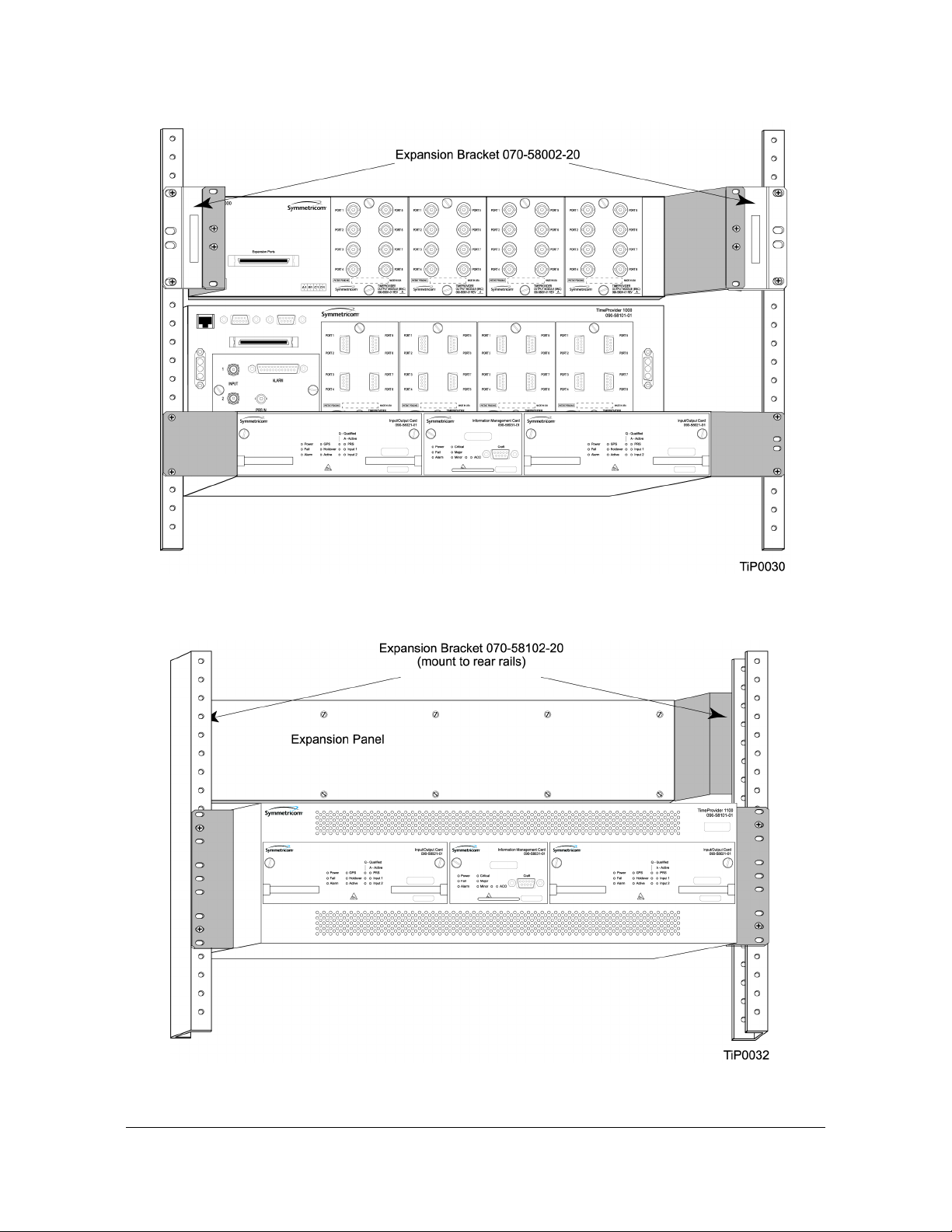
Rack Mounting the Shelf and Expansion Panel
Chapter 3 Installing the TimeProvider
Figure 3-3. Installing the Model 1000 Shelf and Expansion Panel - 23-inch Rack
Figure 3-4. Installing the Model 1100 Shelf and Expansion Panel - 23-inch Rack
097-58001-02 Revision C – August 2005 TimeProvider User’s Guide 53
Page 54

Chapter 3 Installing the TimeProvider
Making Connections
Making Connections
Making Ground Connections
Use the procedure in this section for both the main shelf and the Expansion panel.
After installing the TimeProvider shelf and/or the Expansion panel into the rack,
make the grounding connections as follows.
Recommendation: Although there are a number of methods for
connecting the equipment to earth ground, Symmetricom
recommends running a cable of the shortest possible length from
the ground lug to earth ground.
Front Access Shelf
To connect Chassis Ground on the front access chassis, connect a cable from the
frame ground lug on the left side of the front panel to the proper grounding zone or
master ground bar.
Rear Access Shelf
To connect Chassis Ground on the rear access shelf, connect a cable from Pin 3 of
the power connector to the proper grounding zone or master ground bar.
Expansion Panel
All connections to the Expansion Panel, including chassis ground, are made using
the interconnection cable.
Making Power Connections
The TimeProvider front- and rear-access shelves use different types of power
connectors. Each shelf is delivered with the appropriate connector and shell.
Electrical Shock Caution: To avoid possible injury from shock,
make sure that the fuses are removed from the fuse panel or
power supply before connecting or applying power to the unit.
Warning: For continued fire protection, replace power supply
fuse(s) with the specified type and a 5 A rating. There are no
user-serviceable fuses in the TimeProvider shelf.
This unit must be grounded.
Refer all servicing to qualified personnel.
54 TimeProvider User’s Guide 097-58001-02 Revision C – August 2005
Page 55

Chapter 3 Installing the TimeProvider
Making Connections
To install the TimeProvider power connections:
1. Assemble a power connector appropriate for the type of shelf. Table 3-1 lists the
pin-out for each type of connector.
Rear-access shelf: Crimp a No. 16 AWG (minimum) wire (1.31 mm
then slide the pin into the shell.
Front-access shelf: Assemble the power connector as shown in Figure 3-6.
Solder a No. 16 AWG (minimum) wire (1.31 mm
2
) to each pin. Slip the
appropriate grommet over the wires, and screw the shell together.
2. Attach the connector to the Power A and Power B connectors on the shelf.
Table 3-1. Power Connections
Model 1100 Rear Access (NEBS) Shelf Model 1000 Front Access (ETSI) Shelf
Signal Terminal Signal Terminal
48 Volt Negative Lead 1 Frame Ground 1
48 Volt Positive Lead (return) 2 48 Volt Negative Lead 2
Frame Ground 3 48 Volt Positive Lead (return) 3
Unused 4 – –
2
) to each pin,
Rear Access Shelf Front Access Shelf
Pin 1: -48 V DC Battery
Pin 1: Frame ground
Pin 2: -48 V DC RTN
Pin 3: Frame ground
Pin 4: unused
Figure 3-5. Power Terminal Connectors
097-58001-02 Revision C – August 2005 TimeProvider User’s Guide 55
Pin 2: -48 V DC negative lead
Pin 3: Return
Page 56

Chapter 3 Installing the TimeProvider
Making Connections
Figure 3-6. Assembling the ETSI Power Connector
Expansion Panel
All connections to the Expansion Panel, including power, are made using the
interconnection cable, part number 060-58002-03.
Verifying Power and Grounding Connections
To verify power and grounding connections:
1. Using a DVM, measure the voltage between pins 1 and 2 on the rear access
(NEBS) connector or between pins 2 and 3 of the front access (ETSI) connector.
2. Verify that voltage is –36 to –72 V DC. The inputs are protected against reverse
polarity.
56 TimeProvider User’s Guide 097-58001-02 Revision C – August 2005
Page 57

Chapter 3 Installing the TimeProvider
Making Connections
Making Input Connections
You connect the input signals to the TimeProvider using one of the Input modules
listed in Table 3-2. Connect the Input module to the shelf before you attach cables.
Table 3-2. Input Connector Modules Available for the IOC
Item Number Description Alarm Connector Reference
090-58061-01 BNC Input module DB-25 (see Table 3-6) Figure 3-7
090-58061-02 Wire-wrap Input module Wire-wrap Figure 3-8
090-58061-03 DB9 Input module DB-25 (see Table 3-6) Figure 3-9
090-58061-04 BT43 Input module DB-25 (see Table 3-6) Figure 3-10
090-58061-05 Metric (Siemens) 1.0/2.3
Input module
090-58061-06 Metric (Siemens) 1.6/5.6
Input module
DB-25 (see Table 3-6) Figure 3-11
DB-25 (see Table 3-6) Figure 3-11
Installing the Input Module
Attach the Input module to the shelf and secure it by tightening the screws on each
side of the module.
Figure 3-7. BNC Input Module
097-58001-02 Revision C – August 2005 TimeProvider User’s Guide 57
Page 58
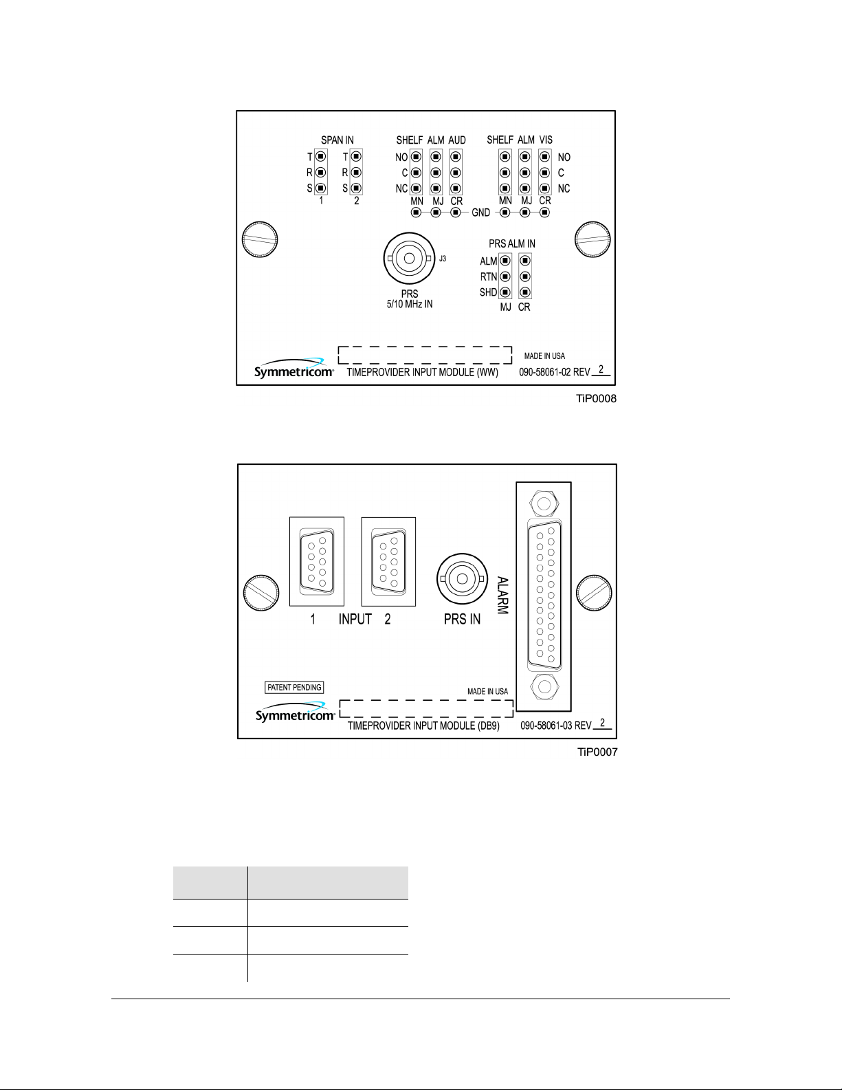
Chapter 3 Installing the TimeProvider
Making Connections
Figure 3-8. Wire-Wrap Input Module
Figure 3-9. DB9 Input Module
The pinout for the DB9 Input module is shown in Table 3-3.
Table 3-3. Pinout for the DB9 Input Module
Pin Description
3 Chassis ground
4 Span Input Tip
8 Span Input Ring
58 TimeProvider User’s Guide 097-58001-02 Revision C – August 2005
Page 59

Figure 3-10. BT43 Input Module
Chapter 3 Installing the TimeProvider
Making Connections
Figure 3-11. Metric (Siemens) Input Module
097-58001-02 Revision C – August 2005 TimeProvider User’s Guide 59
Page 60

Chapter 3 Installing the TimeProvider
Making Connections
Making Output Connections
You make the output signal connections using one of the Output modules listed in
Table 3-4. Attach the module to the shelf before you connect cables.
Table 3-4. Output Connector Modules
Item Number Description Reference
090-58091-01 BNC Output module Figure 3-12
090-58091-02 Wire-wrap Output module Figure 3-12
090-58091-03 DB9 Output module Figure 3-13
090-58091-04 SMZ/BT43 Output module Figure 3-13
090-58091-05 Metric (Siemens) 1.0/2.3 Output
module
090-58091-06 Metric (Siemens) 1.6/5.6 Output
module
090-58081-02 T1 Retimer Output module (wire-wrap) Figure 3-14
090-58082-01 E1 Retimer Output module (BNC) Not shown
090-58082-06 E1 Retimer Output module (Siemens
1.6/5.6)
Figure 3-14
Figure 3-14
Not shown
Installing the Output Module
Attach the Output module to the shelf and secure it using the screws at the top and
bottom of the module.
Table 3-5 lists the pinout for the DB9 Output module, which is shown in Figure 3-13.
Table 3-5. Pinout for the DB9 Output Module
Pin Description
1Port A Tip
2 Port A Ring
4, 5, and 6 Chassis Ground
8Port B Tip
9 Port B Ring
60 TimeProvider User’s Guide 097-58001-02 Revision C – August 2005
Page 61

Chapter 3 Installing the TimeProvider
Making Connections
Figure 3-12. BNC and Wire-Wrap Output Modules
Figure 3-13. DB9 and BT43 Output Modules
097-58001-02 Revision C – August 2005 TimeProvider User’s Guide 61
Page 62

Chapter 3 Installing the TimeProvider
Making Connections
Figure 3-14. Metric (Siemens) Output Module and T1 Retimer Wirewrap Output Module
Making Retimer Connections
The Retimer module (shown in Figure 3-14) performs reshaping, reamplifying, and
retiming on a signal connected to the IN pins on Side 1 (East) and sends that signal
to a Network Element (NE) connected to the OUT pins on Side 1. The signal returns
from the NE on the IN pins of Side 2, where it is reshaped and reamplified and sent
back to the network on the OUT pins of Side 2. Figure 3-15 illustrates how to make
connections to Channel 1 of the Retimer module. See Provisioning the Retimer
Module, on page 112, for the commands to set up the Retiming module.
You can install a Retimer module only in the TimeProvider main shelf in any of the
four Output groups (A, B, C, or D). When you install a Retimer module in any Output
group in a main shelf, the corresponding group on the Expansion Panel can be
user-programmed to any of the output signal types supported by the TimeProvider.
For example, if Group A on the main shelf has the T1 Retimer module installed, then
Group A on the Expansion Panel could have a 2.048 MHz analog output. When an
output group on the main shelf is used for output signals only (no Retimer module is
installed), then the corresponding group on the Expansion Panel has the same
output signal as on the main shelf. For example, if Group A on the main shelf has
2.048 MHz outputs then Group A on the Expansion Panel also has 2.048 MHz
outputs.
62 TimeProvider User’s Guide 097-58001-02 Revision C – August 2005
Page 63

Chapter 3 Installing the TimeProvider
Making Connections
Figure 3-15. Making Retimer Connections
Making Alarm Connections
To install alarm connections on the Input Module, use a customer-supplied DB-25
connector to build an alarm connection to the TimeProvider. Table 3-6 lists the
pinout for the DB-25 Alarm connector found on all the Input modules (except the
wire wrap version).
Table 3-6. Alarm Connector Pinout
Pin Description
1 No Connection
2 Minor Normally Closed (NC) Audible
3 Minor Common Audible
4 Minor NC Visual
5 Minor Common Visual
6 Major NC Audible
7 Major Common Audible
8 Major NC Visual
9 Major Common Visual
097-58001-02 Revision C – August 2005 TimeProvider User’s Guide 63
Page 64

Chapter 3 Installing the TimeProvider
Making Connections
Table 3-6. Alarm Connector Pinout (Continued)
Pin Description
10 Critical NC Audible
11 Critical Common Audible
12 Critical NC Visual
13 Critical Common Visual
14 Ground
15 Minor Normally Open (NO) Audible
16 Critical PRS Input NO
17 Minor NO Visual
18 Critical PRS Input Common
19 Major NO Audible
20 Major PRS Input NO
21 Major NO Visual
22 Major PRS Input Common
23 Critical NO Audible
24 No Connection
25 Critical NO Visible
Pin 1
Pin 25
Figure 3-16. DB-25 Alarm Connector (Front View)
Making GPS Connections
To connect a GPS signal to the TimeProvider, you must install a GPS antenna and
the TimeProvider Interface Unit (TPIU) using the procedure in this section.
Installing the GPS Antenna
These installation procedures are to be used in support of local company
procedures and the Installation Job Specification.
64 TimeProvider User’s Guide 097-58001-02 Revision C – August 2005
Page 65

Chapter 3 Installing the TimeProvider
Making Connections
Prior to installing the antenna, the site, antenna location, lightning suppressor
location, cable route, and all other details should be planned. Use Figure 3-17 as a
guide to locating the antenna.
Figure 3-17. Locating the GPS Antenna
To install the antenna, refer to Figure 3-18, and perform the procedure in this
section. Ensure all user-supplied materials are available. The minimum distance
between the antenna and the shelf is 20 feet (6 m); the maximum distance between
the antenna and the shelf is 1000 feet (304 m).
Warning: To prevent arcing, ensure that the lightning suppressor is
installed away from electrical devices and cabling.
Note: Use the following antenna installation instructions as a
guideline only. Install the antenna using company-approved
techniques, and follow all appropriate local building and electrical
codes.
Recommendation: The TimeProvider uses an antenna that requires
a minimum cable length of 20 feet (6 m) from the antenna to the
TPIU. Symmetricom recommends that you adhere to this minimum
length requirement to ensure proper antenna operation.
097-58001-02 Revision C – August 2005 TimeProvider User’s Guide 65
Page 66

Chapter 3 Installing the TimeProvider
Making Connections
Recommendation: Symmetricom recommends that you use one of
the following grounding points:
Valid roof ring ground system.
Cad weld to building structural steel.
Central office ground plate within 15 m of antenna cable entrance
into building.
Order two cables, or a single cable run can be made from the
antenna to the TimeProvider shelf. The cable can then be cut at the
lightning suppressor location, and TNC connectors attached to the
cut ends of the cable. The “xx” in the part number indicates the cable
length.
Figure 3-18. Antenna-to-Shelf Cabling
66 TimeProvider User’s Guide 097-58001-02 Revision C – August 2005
Page 67

Chapter 3 Installing the TimeProvider
Making Connections
To install the antenna:
1. Attach the antenna mounting bracket to a 1-inch (2.5 cm) diameter pipe or wood
post.
– If you are mounting the bracket to a pipe, assemble as shown in
Figure 3-19. Slide the two V-bolts over the pipe, and through the mounting
bracket slots; then place the provided four washers and four nuts over the
V-bolts, against the mounting bracket. Leave the V-bolts loose enough to
allow for final adjustments.
Figure 3-19. Installing the Antenna Bracket on a Pipe
– If you are mounting the bracket to a wood post, assemble as shown in
Figure 3-20. Install the provided two self-tapping screws in two diagonally
positioned mounting bracket slots, and attach to the post.
Figure 3-20. Installing the Antenna Bracket on a Post
Mount the antenna and mast assembly to the “L” bracket.
097-58001-02 Revision C – August 2005 TimeProvider User’s Guide 67
Page 68

Chapter 3 Installing the TimeProvider
Making Connections
2. Connect the mast to the flange using PVC glue.
3.
Feed an RG58 (060-58545-xx) cable through the bottom of the mast as illustrated.
See Table 2-4 for specific cable lengths.
4. Connect the cable to the antenna “pigtail” and pull the cable back through the mast.
5. Mount the antenna to the mast using the supplied shims.
6. Mount the antenna and mast assembly to the “L” bracket using the supplied nuts,
bolts, and washers, as shown in Figure 3-21.
Figure 3-21. Attaching the Antenna to the Bracket
68 TimeProvider User’s Guide 097-58001-02 Revision C – August 2005
Page 69

Chapter 3 Installing the TimeProvider
Making Connections
7. Using a plumb line or bubble level, ensure the antenna is within 5° of vertical
(perpendicular to the horizon), and tighten the mounting bracket bolts.
8. Bolt the lightning suppressor mounting plate to a flange that is attached to a valid
earth ground. The roof ring ground system, a Central Office grounding plate, and
building structural steel are examples of valid earth ground points. If the
mounting plate cannot be bolted to a valid earth ground, bolt the mounting plate
to a point within 15 feet (4.6 m) of the chosen valid earth ground. If the mounting
plate is to be installed in a nonmetallic junction box, perform the installation and
bolt the assembly near the chosen valid earth ground.
Note: A junction box must have inside dimensions of 7 cm by
7 cm by 4 cm to hold the mounting plate and attached
components.
9. Assemble the lightning suppressor as shown in Figure 3-22.
Figure 3-22. Assembling the Lightning Suppressor
10.Install 1.5 inch (3.8 cm) nonmetallic conduit from the antenna to the lightning
suppressor, and from the lightning suppressor to the cable entrance into the
building.
097-58001-02 Revision C – August 2005 TimeProvider User’s Guide 69
Page 70

Chapter 3 Installing the TimeProvider
Making Connections
11.Install a user-supplied bracket, preferably non-metallic, to support the vertical
section of conduit to the antenna.
12.Route the antenna cable through the conduit, and connect the cable to the
lightning suppressor. See Table 2-4 for specific cable lengths.
13.If the lightning suppressor is not mounted directly to a valid earth ground, crimp a
length of 4.115 mm (6 AWG) ground cable to the two-hole terminal, slide the
terminal over two of the three threaded posts on the lightning suppressor
mounting plate, and attach the terminal to the mounting plate with two KEPS
nuts. Use the two posts that allow the least bending of the cable.
14.Connect an RG58 (060-58545-xx) cable between the lightning suppressor and
the TPIU. See Table 2-4 for specific cable lengths.
15.Install fire-stopping material in all holes opened in the roof and/or walls during
this procedure.
16.Check all connections for tightness to prevent arcing and intermittent operation.
17.Coat all exposed connectors with an electrically conductive antioxidant
compound (e.g. Kopr-Shield spray).
Installing the TPIU
You mount the TPIU on a rack near the TimeProvider main shelf. Symmetricom
supplies the connecting cable (060-58543-xx or 060-58544-xx) in several lengths,
as listed in Table 2-4. The Integrated GPS Antenna kit (990-58545-01 or
990-58545-02). Mount the TPIU to the rear rails of the rack using the provided rack
ears. Install the TPIU so that the front panel is on the same side as the Output
modules. Figure 3-23 and Figure 3-24 illustrate alternate mounting schemes.
To connect the TPIU to the shelf, attach the DB15 interconnect cable (060-58543-03
or 060-58544-03) to the connector labeled “GPS” on the TimeProvider shelf. This
connector is on the front panel of the Model 1000 and on the rear panel of the Model
1100. Connect the other end of the cable to the DB15 connector on the TPIU.
To use the GPS signal, set the TimeProvider to the PRR mode, as described in
Provisioning the IOC, on page 96, or enable the GPS input when in SSU mode.
70 TimeProvider User’s Guide 097-58001-02 Revision C – August 2005
Page 71

Chapter 3 Installing the TimeProvider
Making Connections
Figure 3-23. Mounting the TPIU and Expansion Panel on the Same Rack Ears
Figure 3-24. Mounting the TPIU with a Model 1000 ETSI-Style Shelf
097-58001-02 Revision C – August 2005 TimeProvider User’s Guide 71
Page 72

Chapter 3 Installing the TimeProvider
Making Connections
Making Communications Connections
The Time Provider has one Ethernet and two serial ports available. The Ethernet
connector is on the front panel of the Front Access shelf and on the rear panel of the
Rear Access shelf; the local Craft serial port is on the faceplate of the IMC, and the
Remote port is on the shelf.
The local Craft serial port is used for control and monitoring of the unit, and is
configured as a DCE device. The Remote port can be used for remote dial-in
connection to the unit, and is configured as a DTE device.
Connecting to the Local Craft and Remote Serial Ports
To connect a device to the local Craft or the Remote serial port, perform the
following steps:
1. Connect a 9-pin serial cable to the desired port.
2. Connect the other end of the cable to the serial port of the PC or terminal device.
Use the procedure described in Starting the TimeProvider for the First Time, on
page 82, to connect to the TimeProvider.
The default settings for the local Craft serial port are DCE, 9600 Baud, 8 bits, no
parity, 1 stop bit, echo on, and handshaking disabled. Table 3-7 lists the signal
connections for the serial ports.
Table 3-7. Connector Pinouts for the Serial Ports
Local Craft Connector Remote Connector
Signal Pin Signal Pin
Local CD 1 CD 1
Local RD (Received Data) 2 RD 3
Local TD (Transmitted Data) 3 TD 2
Local DTR (Data Terminal Ready) 4 DTR 6
Ground 5 GND 5
Local DSR (Data Set Ready) 6 DCE 4
Local RTS (Request to Send) 7 RTS 8
Local CTS (Clear to Send) 8 CTS 7
Local RT 9 RT 9
The default settings for the Remote serial port are DTE, 9600 Baud, 8 bits, 1 stop
bit, no parity (also known as 8-1-N), echo on, and handshaking disabled. The local
port settings revert to factory default values when you reset the IMC.
72 TimeProvider User’s Guide 097-58001-02 Revision C – August 2005
Page 73

Installing Connections to the Ethernet Port
Chapter 3 Installing the TimeProvider
Changing Communications Settings
To change the communication settings for the local or remote serial ports:
1. Connect a PC or laptop with terminal emulation software, such as Windows
Hilgraeve HyperTerminal
©
or ProComm Plus™ to the port and log in. For a
complete description of this procedure, see Setting Communications
Parameters, on page 86.
2. Use the ED-EQPT command to change the communications settings for the port
as required. See
Setting Communications Parameters
, on page 86, and also refer
to the TimeProvider TL1 Reference Guide for a description of TL1 commands.
Installing Connections to the Ethernet Port
You can connect a PC or terminal to the TimeProvider using the LAN connector for
local monitoring or control, or you can connect the TimeProvider to a network for
monitoring and control from a remote site.
®
Note: The TimeProvider can be controlled through a TCP/IP
network connection, but before you can use it, you must
configure the Ethernet settings using a serial connection. Refer to
Setting Ethernet Parameters, on page 88.
Direct Ethernet Connection
You use a direct Ethernet connection when a service technician is on-site. You must
configure the Ethernet settings using TL1 commands over a serial connection
before you can use the Ethernet connection. Use the direct connection to
troubleshoot a LAN connection.
To connect the TimeProvider to a PC or terminal, perform the following steps:
1. Connect an RJ-45 Ethernet cable to the LAN connector on the shelf.
2. Connect the other end of the cable to the PC or terminal.
3. Start a terminal emulation program such as HyperTerminal or ProComm Plus.
Configure the program for a telnet session and enter the IP address of the
TimeProvider. Use Port 5000 to connect.
4. Type
; (semicolon). If the TimeProvider responds with a Deny response, you
have established communications. If you do not receive the Deny response,
check the connections, the cable, and the program settings.
097-58001-02 Revision C – August 2005 TimeProvider User’s Guide 73
Page 74

Chapter 3 Installing the TimeProvider
Installing Connections to the Ethernet Port
Network Connection
You can use a network connection for routine monitoring and control of the
TimeProvider from a remote site. Perform the following steps to connect the
TimeProvider to a network.
1. Connect one end of an RJ45 cable to the LAN outlet. Connect the other end of
the cable to the LAN connector on the TimeProvider.
2. To connect the PC or laptop to the LAN, connect one end of the RJ-45 cable to
the Ethernet port of the PC or laptop. Connect the other end of the cable to the
LAN outlet.
3. Use a remote monitoring software application such as SynCraft or TimePictra to
connect to and monitor the TimeProvider. See Appendix B, CRAFT Software
Reference, for more information on installing and using SynCraft.
Table 3-8 lists the Ethernet communications port signal connections.
Table 3-8. Ethernet Communications Port Signal Connections
Name Pin
TX+ (Positive Side of Transmitted Data) 1
TX- (Negative Side of Transmitted Data) 2
RX+ (Positive Side of Received Data) 3
Not Used 4
Not Used 5
RX- (Negative Side of Received Data) 6
Not Used 7
Not Used 8
74 TimeProvider User’s Guide 097-58001-02 Revision C – August 2005
Page 75

Installation Check List
To verify that the installation of the TimeProvider is complete, perform the following
checks and procedures in Table 3-9.
Table 3-9. Installation Completeness Checklist
Operation/Indication Complete
Verify that all power and ground wires are installed correctly and securely.
Verify that all communications cables are properly installed.
Verify that all input and output cables are properly installed.
Powering Up the Shelf
Chapter 3 Installing the TimeProvider
Installation Check List
There is no power switch on the TimeProvider. When you apply power to the unit, it
enters the warm-up state. See Starting the TimeProvider for the First Time, on page
82, for more information on powering up the shelf.
Working With Cards
This section describes how to install, remove, and handle the cards associated with
the TimeProvider.
Properly Handling Cards
When handling any of the cards, observe the following precautions:
1. Use proper static control precautions when handling cards! Protect the
equipment against ESD (electrostatic discharge) by using a grounded protective
wrist strap and normal equipment grounding.
2. Avoid touching component leads and edge connectors.
3. Avoid placing the card on an ungrounded surface.
4. Avoid allowing the card to come in contact with insulated surfaces.
097-58001-02 Revision C – August 2005 TimeProvider User’s Guide 75
Page 76

Chapter 3 Installing the TimeProvider
Working With Cards
Inserting Cards
This procedure is common for all cards.
Note: Cards can be removed and inserted while system power is supplied
without damaging modules; however, system performance may be affected.
Caution: For continued EMC compliance, replace all deformed module
gaskets with the same type. Clean gaskets and mating surfaces. Secure all
cards with captive screws.
To insert a card into the shelf:
1. Align the card edges within the guides of the selected slot.
2. Slide the card into the chassis and press firmly until it seats fully into its
backplane edge connector.
3. Tighten the captive screws located on each side of the panel.
Caution: To avoid possible damage or intermittent failures, ensure that you
have completely inserted the card into the chassis and that you have
securely tightened the captive screws.
Removing Cards
To remove an IOC, lift the tabs on the front panel and slide it out of the shelf. Be
sure to place the card on a static-free surface.
To remove the IMC, Input, or Output modules, loosen and then pull out on the
captive screws.
76 TimeProvider User’s Guide 097-58001-02 Revision C – August 2005
Page 77

Firmware Features
Table 3-10 describes the features provided in recent releases of the operating
firmware for the IOC and IMC.
Table 3-10. Firmware Feature Matrix
IMC Release IOC Release Features Added
1.01.04 1.01.02 E1/T1/2.048 MHz signals
Chapter 3 Installing the TimeProvider
Firmware Features
Quartz IOC
SSMs
1.02.01 1.02.12
1.03.03 1.03.04
GPS
Rubidium IOC
Japanese input/output signals
Composite Clock signals
T1 Retimer
Input/output port labeling
Enhanced event log management
Each higher firmware revision includes support of the features from prior releases.
097-58001-02 Revision C – August 2005 TimeProvider User’s Guide 77
Page 78

Chapter 3 Installing the TimeProvider
Firmware Features
78 TimeProvider User’s Guide 097-58001-02 Revision C – August 2005
Page 79

Chapter 4 Provisioning the TimeProvider
This chapter describes the procedures for provisioning the TimeProvider and the
available Expansion Panel. Use the procedures in this chapter after you have
installed the TimeProvider (see Chapter 3, Installing the TimeProvider).
For detailed information on the syntax and format for each available TL1 command,
refer to the TimeProvider TL1 Reference Guide, part number 097-58001-01.
In This Chapter
TL1 Overview
Starting the TimeProvider for the First Time
Setting Communications Parameters
Defining the Security Parameters
Managing the User List
Provisioning the IOC
Provisioning the Input Reference
Provisioning the Outputs
Provisioning Alarms
System Commands
Saving Provisioning Data
097-58001-02 Revision C – August 2005 TimeProvider User’s Guide 79
Page 80

Chapter 4 Provisioning the TimeProvider
TL1 Overview
TL1 Overview
The TimeProvider uses the TL1 syntax; this chapter and the TimeProvider TL1
Reference Guide describes command lines and responses. For a complete
description of the TL1 syntax, refer to Telcordia (Bellcore) Technical Reference
TR-NWT-00831 and TR-NWT-00833.
TL1 Command Structure
The TL1 commands you issue to the TimeProvider use the following structure:
verb-modifier:|tid|:|aid|:[<ctag>]::|<keyword>|=<value||;
where:
: (colon) is a block separator
, (comma) is a parameter field separator
; (semicolon) is the terminating character for commands and responses
[ ] (square brackets) indicate optional parameters
Adjacent colons indicate unused fields. If an unused field is the last parameter in the
list, for example the general block or the parameter block, you can omit the colon
and simply type the semicolon.
If you enter a space in the command string, the TimeProvider ignores it.
TL1 commands are not case-sensitive.
Table 4-1 describes the syntax used in this manual.
Table 4-1. TL1 Syntax Conventions
Symbol Description
^ Space character (ASCII 0x20)
<cr> Carriage return (ASCII 0x0D)
<lf> Line feed (ASCII 0x0A)
[ ... ] Optional command parameter or data
< ... > ASCII characters sent in commands or returned in response
( ... ) Numeric data that can be positive or negative
80 TimeProvider User’s Guide 097-58001-02 Revision C – August 2005
Page 81

Chapter 4 Provisioning the TimeProvider
TL1 Overview
TL1 Response Format
Normal Response
For each TL1 command described in this chapter there is a normal response, an
in-process response, or an error response. The TimeProvider response is always
upper-case. The format of a normal response is:
<cr><lf><lf>
^^^sid^date^time<cr><lf>
M ^ctag^COMPLD<cr><lf>
;
The time and date is in the Telcordia GR-833 format. A sample normal response is:
TIMEPROVIDER 03-08-28 11:23:54
M 1 COMPLD
;
In-Process Response
The TimeProvider sends an in-process response only if it cannot respond to the
command within two seconds. The response terminates with a less-than character
(<) with no semicolon until after the TimeProvider sends the requested output
response message. The format of the in-process message is:
<cr><lf><lf>
^^^sid^date^time<cr><lf>
IP^ctag<cr><lf>
<
A sample in-process response is:
TIMEPROVIDER 03-08-28 11:24:15
IP^2
<
Error Response
If you mis-type a command or issue an invalid command, the TimeProvider sends
an error message. The format of the error response is:
<cr><lf><lf>
^^^sid^date^time<cr><lf>
M ^ctag^DENY<cr><lf>
^^^<errcde><cr><lf>
;
A sample error message is shown below:
TIMEPROVIDER 08-28-03 11:32:12
M 3 DENY
ICNV
;
097-58001-02 Revision C – August 2005 TimeProvider User’s Guide 81
Page 82

Chapter 4 Provisioning the TimeProvider
Starting the TimeProvider for the First Time
The TL1 command may generate an event message specific to the command. This
event message accompanies the command description in this chapter.
Autonomous Messages
In addition to the TL1 response messages described in the above sections, the
TimeProvider returns Autonomous Messages to report alarms, configuration
changes, or condition changes. Frequently, an Autonomous Message is returned at
approximately the same time as the TL1 response message that is associated with
a command, because the command happens to change the unit’s state.
Autonomous Messages are not directly correlated with commands, and therefore
they do not contain a correlation tag (ctag).
The TimeProvider can generate an Autonomous Message at any time, whether to
report that a user-initiated change has occurred, to report that an active alarm
condition exists, or to report that an alarm has been cleared. The format of the
Autonomous message is as follows; note that the text REPT identifies the response
as a Autonomous Message.
<cr><lf><lf>
sid date time <cr><lf>
almcde atag REPT reptype aidtype<cr><lf>
aid,aditype:ntfcncde,condtype,srveff,ocrdat,ocrtim:condscr
”<cr><lf>
;
Refer to the TimeProvider TL1 Reference Guide for more information on
Autonomous Messages.
Starting the TimeProvider for the First Time
The TimeProvider is delivered with a copy of SynCraft, Symmetricom’s network
management application. Before you can use SynCraft or other network
management software, you must provision the following parameters, as described
in this section and in Setting Communications Parameters, on page 86:
Security-level user
Source ID (sid)
Date and time
Serial communications parameters
Ethernet parameters
Appendix B, CRAFT Software Reference, provides procedures and instructions to
get started using the SynCraft application.
82 TimeProvider User’s Guide 097-58001-02 Revision C – August 2005
Page 83

Chapter 4 Provisioning the TimeProvider
Starting the TimeProvider for the First Time
Powering Up the TimeProvider
To power up the TimeProvider, perform one of the following tasks, as appropriate:
Connect the power leads from the power supply (see Making Power
Connections, on page 54)
Install the fuse in the fuse panel
Turn on the power supply
LED Indications on Power-up
The LEDs on the IMC, IOC, and TPIU (if present) illuminate in the following
sequence:
The LEDs on the TPIU remain off until the Master shelf has completed its power-on
testing and the GPS input has been enabled. The TPIU and Antenna Power LEDs
light green and the Antenna Signal LED lights red. When the Master shelf
completes its power-on testing, the Antenna Signal LED lights green, indicating that
the TPIU is receiving a valid signal from the antenna.
Logging In for the First Time
To log in to the TimeProvider for the first time:
1. Connect a straight-through serial cable to the local Craft port. Connect the other
end of the cable to a computer.
2. Start a terminal emulation program such as HyperTerminal or ProComm Plus.
Configure the program for 9600 baud, 8 data bits, No parity, and 1 stop bit.
3. Type
; (semicolon). If the TimeProvider responds with a Deny response, you
have established communications. If you do not receive the Deny response,
check the connections, the cable, and the program settings.
Defining a User at the Security Access Level
Recommendation: To avoid a possible service call to unlock the
TimeProvider, Symmetricom recommends that you enable the
security feature by defining a user at the Security access level.
TimeProvider Access Levels
The security measures built into the TimeProvider are based on a list of users
authorized to access the unit. Each user has their own password and is assigned to
one of the following access levels: NONE, USER, ADMIN, or SECURITY. Users can
issue the TL1 commands available at their access level. Managing the User List, on
page 90, describes how to manage the user list.
If you do not define a Security-level user, the security features are not enabled and
an unauthorized user could gain access to the TimeProvider and compromise the
security of your network.
097-58001-02 Revision C – August 2005 TimeProvider User’s Guide 83
Page 84

Chapter 4 Provisioning the TimeProvider
Starting the TimeProvider for the First Time
If you define a user at a level other than Security before you define a Security-level
user, you cannot execute Security-level commands. You will need to contact
Symmetricom Global Services to correct this problem.
Recommendation: Symmetricom recommends that you record
and store the Security-level user’s name and password in a
secure location.
Adding a User at the Security Access Level
To define a user at the Security access level, issue the following TL1 command:
Sample Command
ENT-USER-SECU::DEPTHEAD:TS1000::”TP01!”,SECURITY;
This sample command creates a user with the name DEPTHEAD and a password
of TP01!; this user is at the Security access level. See Adding a User, on page 92,
for more information on the ENT-USER-SECU command.
Autonomous Message
TP-SSU 03-05-15 09:59:09
A 1166 REPT EVT
“IMC:NA,USRADD,NSA,03-05-15,09-59-09:\”USER HAS BEEN
ADDED\””
;
Logging In
You can now log in using the ACT-USER command and the new user name and
password to continue with the provisioning process.
Sample Command
ACT-USER::DEPTHEAD:TS1000::TP01!;
Normal Response
TP-SSU 03-05-15 09:59:15
M TS1000 COMPLD
;
Users with the Security access level can issue any of the TL1 commands described
in this chapter and in the TimeProvider TL1 Reference Guide.
Setting the Source ID <sid>
Use the SET-SID command to set the name of the TimeProvider. This name
appears in normal and error response messages sent by the unit.
SET-SID:[<tid>]::[<ctag>]::<keyword>=<value>;
This command has a default access level of ADMIN.
84 TimeProvider User’s Guide 097-58001-02 Revision C – August 2005
Page 85

Chapter 4 Provisioning the TimeProvider
Starting the TimeProvider for the First Time
<keyword> <value> Description Default value
SIDCHG Up to 20 alphanumeric
characters. Do not use
the “ character.
Sets the Source
Identifier
N/A
Sample Command
SET-SID:::TS1000::SIDCHG=TP-SSU;
This sample command sets the <sid> to TP-SSU. All response messages are
identified by this name. Symmetricom recommends that you use unique names for
each TimeProvider in the network. Record the name you chose for the
TimeProvider in Table 4-3.
If you include the _ character in the <value>, then the TimeProvider returns the SID
in quote marks.
Autonomous Message
TP-SSU 03-05-15,10:02:03
A 1167 REPT EVT
“IMC,EQPT:NA,SIDCHG,NSA,03-05-15,10-02-03:\”SYSTEM’S
SOURCE ID HAS CHANGED,TP-SSU\””
;
Setting the Date and Time
Use the following TL1 command to set the date and time in the IMC.
ED-DAT:[<tid>]:[<aid>]:[<ctag>]::<keyword>=<value>;
This command has a default access level of ADMIN.
<aid> <keyword> <value> Description
SYS DATCHG
<yy-mm-dd>
TIMCHG
(hh-mm-ss)
LOCTIM
(
±hh-mm)
yy = <year>
mm = 01 to 12
dd = 01 to 31
hh = 00 to 23
mm = 00 to 59
ss = 00 to 59
±hh = 00 to 12
mm = 00 to 59
2-digit year
Month
Day
Hour of Day
Minutes
Seconds
Time in hours and minutes that local time is
offset from UTC.
Sample Command
ED-DAT::SYS:TS1000::DATCHG=03-10-24;
097-58001-02 Revision C – August 2005 TimeProvider User’s Guide 85
Page 86

Chapter 4 Provisioning the TimeProvider
Setting Communications Parameters
Autonomous Message
TP-SSU 03-10-24 10:08:28
A 1168 REPT EVT
SYS,EQPT:NA,DATCHG,NSA,03-10-24,10-08-28:\"SYSTEM DATE
HAS CHANGED,2003-10-24\””
;
Setting Communications Parameters
If you want to change the communications parameter values, use the ED-EQPT
command. The following sections describe the commands for performing each
individual task. For detailed information on the ED-EQPT command, see the
TimeProvider TL1 Reference Guide. Record the values you provision in Table 4-3.
Setting RS-232 Parameters
This section describes how to set the baud rate, the handshaking mode, and echo
modes on the local and remote ports.
Setting the Baud Rate
Use the ED-EQPT command to provision the baud rate on the Local or Remote
port.
ED-EQPT:[<tid>]:<aid>:[<ctag>]::<keyword>=<value>;
This command has a default access level of ADMIN.
<aid> <keyword> <value> Description Default value
COMp
p = L | R
BAUD 2400 | 9600 |
19200 | 28800 |
38400 | 57600
Communications ports
L = Local
R = Remote
Baud rate 9600
Sample Command
ED-EQPT::COML:TS1000::BAUD=9600;
This command sets the local Craft communications port to 9600 baud.
Normal Response
TIMEPROVIDER 03-10-24 10:10:25
M TS1000 COMPLD
;
86 TimeProvider User’s Guide 097-58001-02 Revision C – August 2005
Page 87

Chapter 4 Provisioning the TimeProvider
Setting Communications Parameters
Setting the Handshaking (Flow) Mode
Use the ED-EQPT command to provision the handshaking mode on the local Craft
or Remote port to None, Hardware, Software, or Hardware/Software.
ED-EQPT:[<tid>]:<aid>:[<ctag>]::<keyword>=<value>;
This command has a default access level of ADMIN.
<aid> <keyword> <value> Description Default value
COMp
p = L | R
Communications ports
FLOW NONE | SW |
HW | SWHW
Flow control NONE
Sample Command
ED-EQPT::COML:TS1000::FLOW=HW;
Normal Response
TIMEPROVIDER 03-10-24 10:12:33
M TS1000 COMPLD
;
Setting the Echo Mode
Use the ED-EQPT command to provision the echo mode on the local Craft or
Remote port to On or Off. When set to ENABLE, characters you type at the
keyboard also appear on the monitor. If one keystroke generates two characters on
the monitor, set this parameter to DISABLE.
You can also use this command to echo the <tid> in the response from the
TimeProvider.
ED-EQPT:[<tid>]:<aid>:[<ctag>]::<keyword>[=<value>];
This command has a default access level of ADMIN.
<aid> <keyword> <value> Description Default value
COMp
p = L | R
ECHO ENABLE | DISABLE Input echo DISABLE
TIDQUIET ENABLE | DISABLE Enables or disables the
Communications ports
DISABLE
echo of the <tid>. This
is a session setting.
Sample Command
ED-EQPT::COML:TS1000::ECHO=ENABLE;
097-58001-02 Revision C – August 2005 TimeProvider User’s Guide 87
Page 88

Chapter 4 Provisioning the TimeProvider
Setting Communications Parameters
Normal Response
TIMEPROVIDER 03-10-24 10:15:04
M TS1000 COMPLD
;
Setting Ethernet Parameters
Before you can begin using the Ethernet port, you must provision the addresses
using the local Craft or Remote serial port.
If you are not planning to use the Ethernet port, you do not have to provision the
parameters in this section.
Setting the IP Addresses
Use the ED-EQPT command to provision the following IP addresses for the
TimeProvider:
IP Gate address
IP address
IP Subnet address
You can also use this command to echo the <tid> in the response from the
TimeProvider.
ED-EQPT:[<tid>]:<aid>:[<ctag>]::<keyword>=<value>;
This command has a default access level of ADMIN.
<aid> <keyword> <value> Description Default
COMI Comms ports
IPGATE 1.0.0.1
254.255.255.254
IPADDR 1.0.0.1
254.255.255.254
IPSUBNET 1.0.0.1
255.255.255.254
TIDQUIET ENABLE |
DISABLE
IP address of the default gateway 127.0.0.1
IP address of the Network
Element
IP address of the Network
Element
Enables or disables the echo of
the <tid>. This is a session
setting.
127.0.0.1
255.255.
255.0
DISABLE
Sample Command
ED-EQPT::COMI:TS1000::IPGATE=127.0.0.1;
This command sets the IP Gate address to 127.0.0.1. Use an appropriate gateway
address for your network, and record the address in Table 4-3.
88 TimeProvider User’s Guide 097-58001-02 Revision C – August 2005
Page 89

Chapter 4 Provisioning the TimeProvider
Setting Communications Parameters
Autonomous Message
TP-SSU 03-10-24 10:15:04
A 1169 REPT EVT
“COMI:NA,IPGATE,NSA,03-10-24 10-15-04:\”IP GATE ADDRESS
HAS CHANGED\””
;
Checking Communication Links
Two commands allow you to check the communication links from a computer or
network to the TimeProvider: PING and RTRV-HDR.
Ping
Use the PING command to check an Ethernet connection to the TimeProvider.
PING:[<tid>]::[<ctag>]::<ipaddr>;
This command has a default access level of USER.
<ipaddr> Value Description
IP address of host to be pinged 1.0.0.1 – 254.254.254.254 Pings the host system
Sample Command
PING:::TS1000::192.168.12.10;
Normal Response
TP-SSU 03-05-15 09:59:09
M TS1000 COMPLD
“Host 192.168.12.10 is alive. Roundtrip time was 165 ms”
;
Retrieve Header
Use the RTRV-HDR command to display the response header, which includes the
system identification <sid>, date, and time. You can also use this command to verify
that the communication link to the TimeProvider is working properly.
This command has a default access level of NONE.
Sample Command
RTRV-HDR:::TS1000;
Normal Response
TP-SSU 03-05-15 09:59:25
M TS1000 COMPLD
;
097-58001-02 Revision C – August 2005 TimeProvider User’s Guide 89
Page 90

Chapter 4 Provisioning the TimeProvider
Defining the Security Parameters
Defining the Security Parameters
The TimeProvider supports users at the following four access levels:
None – Anyone with access to a serial or Ethernet port on the TimeProvider can
issue commands set to this access level. If no Security-level users are defined,
then anyone connected to the TimeProvider can issue every command available
User – Users entered into the user list at the User level can issue commands set
at the User access level
Admin – Users entered into the user list at the Admin level can issue commands
set at the Admin access level
Security – Users at this access level can issue every command available
You can edit the commands available at each access level using the
ED-CMD-SECU command. You can display the current access level for each
command by issuing the RTRV-CMD-SECU command. See the TimeProvider TL1
Reference Guide for details on these commands. Record the values you provision
in Table 4-3.
The first person to log into the TimeProvider is automatically assigned the Security
access level (described in Defining a User at the Security Access Level, on page
83); this person normally performs the initial provisioning and defines users and
their appropriate access levels.
Managing the User List
Use the procedures in this section to manage the users that are authorized to
access the TimeProvider.
Logging In
Use the following TL1 command to log existing users into the system.
ACT-USER:[<tid>]:<uid>:[<ctag>]::<pid>;
This command has a default access level of NONE.
90 TimeProvider User’s Guide 097-58001-02 Revision C – August 2005
Page 91

Chapter 4 Provisioning the TimeProvider
Parameter <uid> Value Description
<uid> <username> Up to 20 case-insensitive characters Assigned user
Managing the User List
name
<pid> password Up to 20 case-sensitive characters. Must include
at least two non-alphabetic and one special
character (any printing character other than a
letter, number, comma, colon, or semicolon. For
case-sensitive passwords, enclose the <pid> in
quotes, for example “sYmm!23”
Sample Command
ACT-USER::TECHNICIAN:TS1000::TECH01!;
This command logs in the user named Technician.
Autonomous Message
TP-SSU 03-10-24 10-18-24
A 1170 REPT EVT
“IMC:NA,LOGIN,NSA,03-10-24 10-18-24:\”USER LOGGED IN,
TECHNICIAN\””
;
Error Response
TP-SSU 03-10-24 10-18-24
M 04 DENY
<errcode>
”UNAUTHORIZED ACCESS TO THIS SYSTEM IS PROHIBITED.”
;
Assigned
password
Logging Out
Use the following TL1 command to terminate a session and log out of the system.
Security-level users can terminate any other user. The username is not
case-sensitive, but it must be spelled exactly as assigned.
CANC-USER:[<tid>]:[<uid>]:[<ctag>];
This command has a default access level of USER.
<uid> Value Description
null Terminates the current user’s session and
logs the user off the system
<uid> Up to 20 case-
insensitive characters
097-58001-02 Revision C – August 2005 TimeProvider User’s Guide 91
Allows a user at the ADMIN or SECURITY
level to terminate another user’s session
Page 92

Chapter 4 Provisioning the TimeProvider
Managing the User List
Sample Command
CANC-USER::TECHNICIAN:TS1000;
This command logs out the user named Technician.
Autonomous Message
TP-SSU 03-10-24 10:25:31
A 1171 REPT EVT
“IMC,EQPT:NA,LOGOUT,NSA,03-10-24 10-25-31:\”USER LOGGED
OUT,TECHNICIAN\””
;
Adding a User
You can store up to 20 users in the TimeProvider’s user list. Each user has a name
of up to 20 case-insensitive alphanumeric characters, a password of up to 10
case-sensitive characters, and one of the four defined access levels.
Use the following TL1 command to add a user to the user list. If more than 20 users
are defined in the user list, the DENY response is sent. Only a Security-level user
can add to the user list.
ENT-USER-SECU:[<tid>]:<uid>:[<ctag>]::<pid>,<uap>;
This command always has a access level of SECURITY.
Parameter Value Description
<uid> <username> Up to 20 case-insensitive alphanumeric characters
<pid> <user password> Up to 20 case-sensitive characters. You must include at
least two non-alphabetic and one special character (other
than a letter, number, comma, colon, or semicolon). For
case-sensitive passwords, enclose the <pid> in quotes.
<uap> NONE | USER |
ADMIN | SECURITY
The access level for the user specified by the <uid>
Sample Command
ENT-USER-SECU::TECHNICIAN:TS1000::TECH01!,USER;
This command creates a user named TECHNICIAN with a password of TECH01! at
the User access level.
Autonomous Message
TP-SSU 03-10-24 10:28:24
A 1172 REPT EVT
“IMC:NA,USRADD,NSA,03-10-24 10-28-24:\”USER HAS BEEN
ADDED\””
;
92 TimeProvider User’s Guide 097-58001-02 Revision C – August 2005
Page 93

Chapter 4 Provisioning the TimeProvider
Managing the User List
Changing the Current User’s Password
The ED-PID command changes the specified user’s password.
ED-PID:[<tid>]:[<uid>]:[<ctag>]::<oldpid>,<newpid>;
This command has a default access level of USER.
Keyword Value Description
<uid> <username> Up to 20 case-insensitive
alphanumeric characters
<oldpid> Must match existing value or
DENY is issued for the command
<newpid> Up to 20 case-sensitive
characters
Old password for the
specified user
New password for the
specified user
Sample Command
ED-PID::TECHNICIAN:TS1000::TECH01!,#Tech02;
This command changes the current user’s password from TECH01! to #Tech02.
Autonomous Message
TP-SSU 03-10-24 10:30:01
A 1173 REPT EVT
“IMC:NA,PIDCHG,NSA,03-10-24 10-30-01:\”USER PASSWORD HAS
CHANGED\””
;
Displaying a User’s Access Level
Use the following TL1 command to display the access level for a specified user or
for all users.
RTRV-USER-SECU::[<uid>]:[<ctag>];
This command always has a access level of SECURITY.
Parameter Description
<uid> Assigned user name. Displays the access
level of the specified user.
null Displays the access level for all assigned
user names.
097-58001-02 Revision C – August 2005 TimeProvider User’s Guide 93
Page 94

Chapter 4 Provisioning the TimeProvider
Managing the User List
The response format is:
<cr><lf><lf>
^^^sid^date^time<cr><lf>
M ^ctag^COMPLD<cr><lf>
^^^”username,access”<cr><lf>
^^^”username,access”<cr><lf>
.
.
.
^^^”username,access”<cr><lf>
;
Response Value Description
<username> Up to 20 case- insensitive characters Assigned user name
<access> NONE | USER | ADMIN | SECURITY Access level
Sample Command
RTRV-USER-SECU::TS1000;
Normal Response
TP-SSU 03-10-24 10:31:31
M TS1000 COMPLD
“TECHNICIAN,USER”
“DEPTHEAD,SECURITY”
“DAVID,ADMIN”
;
Editing a User’s Access Level
Use the following TL1 command to change the access level for a specified user.
ED-USER-SECU:[<tid>]:<uid>:[<ctag>]::<keyword>=<value>;
This command always has a access level of SECURITY.
Parameter <keyword> <value> Description
<uid> Up to 20 case-insensitive characters Assigned user name
ACCLVL NONE | USER | ADMIN | SECURITY New access level for
the specified user
Sample Command
ED-USER-SECU::TECHNICIAN:TS1000::ACCLVL=ADMIN;
This command changes the access level for the TECHNICIAN user to ADMIN.
94 TimeProvider User’s Guide 097-58001-02 Revision C – August 2005
Page 95

Chapter 4 Provisioning the TimeProvider
Managing the User List
Autonomous Message
TP-SSU 03-10-24 10:33:04
A 1174 REPT EVT
“IMC,EQPT:NA,ACCLVL,NSA,03-10-24 10-33-04:\”USER ACCESS
LEVEL HAS CHANGED\””
;
Deleting A User
Use the following TL1 command to delete a specified user from the user list.
DLT-USER-SECU:[<tid>]:<uid>:[<ctag>];
This command has a default access level of SECURITY.
Parameter Value Description
<uid> Up to 20 case-insensitive characters Assigned user name
Sample Command
DLT-USER-SECU::TECHNICIAN:TS1000;
This command deletes the TECHNICIAN user from the user list.
Autonomous Message
TP-SSU 03-10-24 10:35:54
A 1175 REPT EVT
“IMC:EQPT:NA,USRDEL,NSA,03-10-24 10-35-54:\”USER HAS BEEN
DELETED\””
;
Retrieving Current Users
Use the RTRV-USER command to display a list of all currently connected users.
The TimeProvider supports up to 10 TCP simultaneous connections, as well as one
local and one remote serial connection. If a user is logged on, the username
appears in the response.
RTRV-USER:[<tid>]::[<ctag>];
This command has a default access level of USER.
Sample Command
RTRV-USER;
Normal Response
TP-SSU 03-10-24 10:37:14
M ^04^COMPLD
TECHNICIAN
;
097-58001-02 Revision C – August 2005 TimeProvider User’s Guide 95
Page 96

Chapter 4 Provisioning the TimeProvider
Provisioning the IOC
Provisioning the IOC
This section describes how to provision the IOC.
Setting the System Mode
The SET-SYS-MODE command allows you to provision the operating mode of the
TimeProvider to one of the following:
SSU – Synchronization Supply Unit: provides filtering compliant with G.812 and
GR-1244
SUB – Subtending mode: provides composite clock input tracking compliant with
GR-378
PRR – Primary Reference Receiver mode: provides ITU-T G.811 and Telcordia
GR-2830 requirements for Primary Reference Receivers/Clocks
In the SSU mode, you can select the system reference from signals on the PRS,
INP1, or INP2 connectors.
In the SUB mode, the PRS input is set to Monitor only; you can select the system
reference from signals on the INP1 or INP2 connectors. You can provision these
inputs to Composite Clock signal types only when the TimeProvider is in SUB mode.
In the PRR mode, the antenna provides GPS signals as the primary reference. You
can use qualified and enabled signals on INP1 and INP2 to enhance the stability of
the output signals based on the BesTime algorithm.
Setting the System Mode
Use the SET-SYS-MODE command to provision the TimeProvider’s operating
mode. See Operating Modes, on page 24, for more information on how the
operating mode affects the TimeProvider’s inputs and outputs.
SET-SYS-MODE:[<tid>]::[<ctag>]::<keyword>=<value>;
This command has a default access level of ADMIN.
96 TimeProvider User’s Guide 097-58001-02 Revision C – August 2005
Page 97

Chapter 4 Provisioning the TimeProvider
Provisioning the IOC
<keyword> <value> Description Default value
SYSMODE SSU Set the TimeProvider to SSU operating mode
PRS – Priority 1 and Enabled
INP1 – Priority 2 and Enabled
INP2 – Priority 3 and Enabled
GPS – Disabled
SUB
Set the TimeProvider to Subtending operating mode
PRS – Monitor only and Disabled, cannot be
Enabled
INP1 – Priority 1 and Enabled
INP2 – Priority 2 and Enabled
GPS – Monitor only and Disabled, cannot be
Enabled
PRR Set the TimeProvider to Primary Reference
Receiver mode
PRS – Enabled as Backup Reference, can be
set to Monitor or Disabled
INP1 – Enabled as Backup Reference, can be
set to Monitor or Disabled
INP2 – Enabled as Backup Reference, can be
set to Monitor or Disabled
GPS – Enabled and Priority 1
SSU
Sample Command
SET-SYS-MODE:::TS1000::SYSMODE=SUB;
Sets the system mode to Subtending (SUB). The inputs are set as described in the
table above. Record the mode in Table 4-3.
Autonomous Message
TP-SSU 03-10-24 10:40:10
A 1176 REPT EVT
“SYS,EQPT:NA,SYSMODE,NSA,03-10-24 10-40-10:\"SYSTEM MODE
OF OPERATION HAS CHANGED,SUB\””
;
Retrieving the Current System Mode
Use the following TL1 command to retrieve the current system mode.
RTRV-SYS-MODE:[<tid>]::[<ctag>];
This command has a default access level of USER.
Response Description
<value> SSU | SUB | PRR
097-58001-02 Revision C – August 2005 TimeProvider User’s Guide 97
Page 98

Chapter 4 Provisioning the TimeProvider
Provisioning the IOC
Sample Command
RTRV-SYS-MODE:::TS1000;
Normal Response
TP-SSU 03-10-24 10:37:54
M TS1000 COMPLD
SSU
;
Setting the IOC Parameters
Use the ED-EQPT command to provision each IOC. This command allows you to
select which IOC is Active and which is Standby; to switch the Active and Standby
IOCs; to place a IOC “In Service” or “Out of Service”; and to define the oscillator type
to Type I or ST3E for a quartz-based IOC or to Type II or ST2 for a Rubidium IOC.
ED-EQPT:[<tid>]:<aid>:[<ctag>]::<keyword>=<value>;
This command has a default access level of ADMIN.
<aid> <keyword> <value> Description Default value
IOCm
m = 1 | 2
IOCMODE ACTIVE |
STANDBY
IOCACTV n/a Sets the Standby IOC to Active n/a
IOCSTATE INSRV Places an “Out of Service” IOC
OOSRV
CLKTYPE ST2/TYPEII |
ST3/TYPEI
IOC module
Sets the mode of the
IOC. For redundant systems,
changing the state of one IOC
forces the other IOC to the
alternate state
in the “In Service” mode
(restarts)
Places an “In Service” IOC in the
“Out of Service” mode. An Out of
Service IOC cannot generate
outputs or monitor inputs and
does not generate alarms
Defines the Local Oscillator
type. Selects the type of clock
used to generate SSMs in
Holdover mode
specified
ACTIVE
INSERV
TYPEI
Sample Command
ED-EQPT::IOC1:TS1000::IOCSTATE=INSERV;
This command places IOC 1 in the “In Service” mode. Use this command when you
have taken an IOC out of service and are now ready to put it back in service.
98 TimeProvider User’s Guide 097-58001-02 Revision C – August 2005
Page 99

Autonomous Message
TP-SSU 03-10-24 10:42:40
A 1177 REPT EVT
"IOC1,EQPT:NA,IOCSTATE,NSA,03-10-24 10-42-40:\"IOC STATE
HAS CHANGED,INSRV\"
;
Provisioning the Input Reference
You need to know the following information about the input reference signal before
you can provision the Input Reference signals:
Input selection mode
Interface type
Frame type/frequency
Quality level
Chapter 4 Provisioning the TimeProvider
Provisioning the Input Reference
Priority level
SSMs and bit position
CRC
Setting the Input State
Use the ED-EQPT command to provision the inputs to the TimeProvider. You can
enable, disable, or place an input in Monitor mode (where the input is monitored, but
cannot be selected as the system reference).
ED-EQPT:[<tid>]:<aid>:[<ctag>]::<keyword>=<value>;
This command has a default access level of ADMIN.
<aid> <keyword> <value> Description Default value
PRS
INPp (p = 1 | 2)
GPS
INSTATE ENABLE Enables the specified input ENABLE
MONITOR Places the specified input in
System inputs
GPS = DISABLE
Monitor Only mode.
DISABLE Disables the specified input
Sample Command
ED-EQPT::INP1:TS1000::INSTATE=MONITOR;
This command places Input 1 in the Monitor mode.
097-58001-02 Revision C – August 2005 TimeProvider User’s Guide 99
Page 100

Chapter 4 Provisioning the TimeProvider
Provisioning the Input Reference
Autonomous Message
TP-SSU 03-10-24 10:44:21
A 1178 REPT EVT
“INP1,T1:NA,INSTATE,NSA,03-10-24 10-44-21:\"INPUT STATE
HAS CHANGED,MONITOR\””
;
Setting the GPS Parameters
After you install the GPS antenna, you must provision the parameters using the
ED-EQPT command.
ED-EQPT:[<tid>]:<aid>:[<ctag>]::<keyword>=<value>;
This command has a default access level of ADMIN.
<aid> <keyword> <value> Description Default value
GPS GPS input, except clock input
signals
MODE AUTO The antenna position (latitude,
longitude, and elevation) is
automatically computed or
recomputed and set
MANUAL The position (latitude, longitude,
and elevation) is set manually using
the POS keyword
POS
Note: The
position can
only be set
when Mode
is MANUAL
ELEVMASK 5 to 45 The elevation mask, below which
LAT dd-mm-ss.ssN or
dd-mm-ss.ssS
LONG dd-mm-ss.ssE or
dd-mm-ss.ssW
ELEV hhhh.hh height in m
the TimeProvider will not track or
acquire a satellite
AUTO
n/a
10
Sample Command
ED-EQPT::GPS:TS1000::MODE=AUTO;
This command sets the GPS location mode to Automatic. The location of the GPS
antenna is determined from multiple satellite fixes.
100 TimeProvider User’s Guide 097-58001-02 Revision C – August 2005
 Loading...