

Page 1
MC17/MC17T
Quick Reference Guide
Page 2

2 MC17 Mobile Computer
© 2007-8 MOTOROLA, INC. All rights reserved.
Motorola reserves the right to make changes to any
product to improve reliability, function, or design.
Motorola does not assume any product liability arising
out of, or in connection with, the application or use of
any product, circuit, or application described herein.
No license is granted, either expressly or by implication,
estoppel, or otherwise under any patent right or patent,
covering or relating to any combination, system,
apparatus, machine, material, method, or process in
which Motorola products might be used. An implied
license exists only for equipment, circuits, and
subsystems contained in Motorola products.
MOTOROLA, the Stylized M Logo and Symbol and the
Symbol logo are registered trademarks of Motorola, Inc.
Other product names mentioned in this manual may be
trademarks or registered trademarks of their respective
companies and are hereby acknowledged.
Motorola, Inc.
One Motorola Plaza
Holtsville, N.Y. 11742-1300 USA
http://www.motorola.com/enterprisemobility
Warranty
For the complete Motorola hardware product warranty
statement, go to:
http://www.motorola.com/enterprisemobility/warranty
.
Patents
This product is covered by one or more patents. For
patent information go to:
http://www.motorola.com/enterprisemobility/patents
.
Page 3
Quick Reference Guide 3
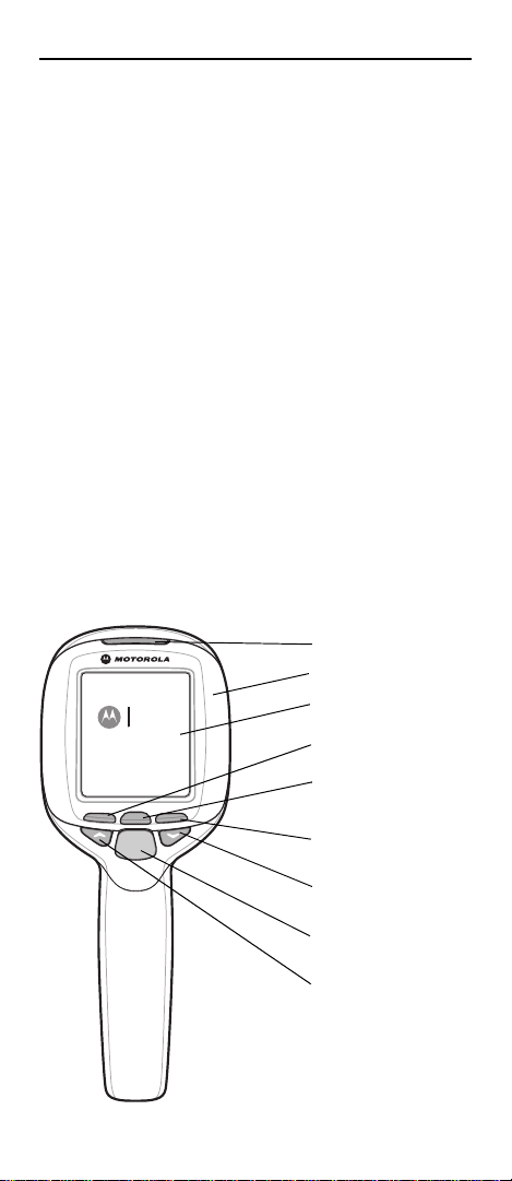
Scan key
LED
Display
Scroll Right key
Scroll Down key
Scroll Up key
Enter key
Scroll Left key
Bezel
Introduction
This Quick Reference Guide explains how to install and
charge the battery, scan bar codes, reset, maintain and
troubleshoot the mobile computer.
Unpacking
Carefully remove all protective material from around the
mobile computer and save the shipping container for
later storage and shipping.
Verify that you received all equipment listed below:
• MC17 mobile computer
• Lithium-ion battery (2400 mAh) inside handle
• Quick Reference Guide.
Inspect the equipment for damage. If you are missing
any equipment or if you find any damaged equipment,
contact the Motorola Enterprise Mobility Support
immediately. See Service Information on backcover for
contact information.
Features
MC17
series
Page 4
4 MC17 Mobile Computer
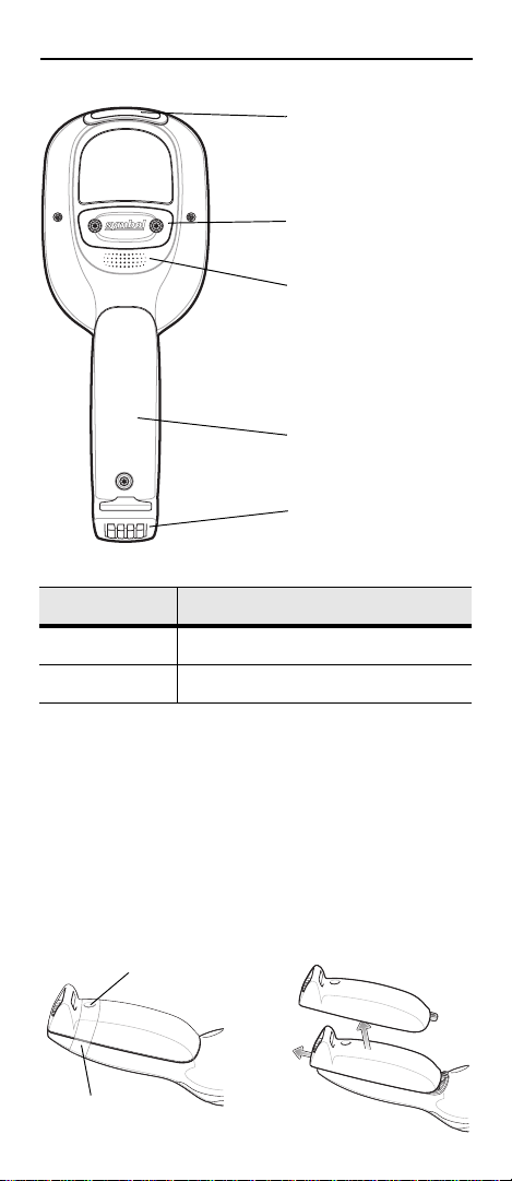
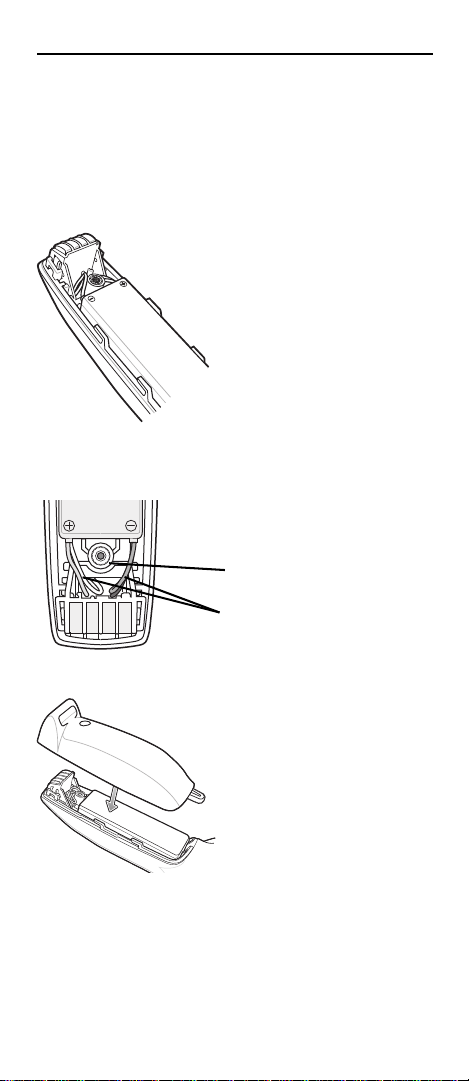
Battery Cover
Power Connector
Scan Exit Window
Access Cover
Speaker
Ta pe
Screw Under Tape
LED State Description
Solid Red Scanner is enabled.
Solid Green Bar code decode successful.
Getting Started
In order to start using the mobile computer you must
install the battery and then charge it.
Connecting the Battery
1. Remove tape securing battery cover to handle.
2. Remove screw from screw hole (under tape).
3. Slide the battery cover toward the bottom of the
handle and then lift.
Page 5
Quick Reference Guide 5
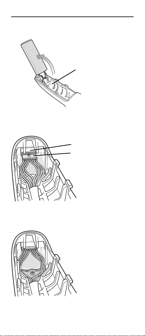
Black Rubber Pad
PCB Connector
Harness Connector
4. Lift the battery from the battery compartment and
support so that the harness wires are not extended.
5. Remove the black rubber pad from the battery
compartment.
6. Align the harness connector with the connector on
the printed circuit board (PCB).
7. Push the harness connector into the PCB connector.
Use a plastic tool to ensure that the harness
connector is fully seated.
8. Spread the wires out evenly as shown below.
9. Ensure that the harness connector is fully mated with
the PCB connector.
Page 6
6 MC17 Mobile Computer
Harness Wires
Screw Boss
10.Replace the black rubber pad into the compartment
ensuring that it is lying flat along the bottom of the
compartment, with its smoother side facing up, and
the rubber “fingers” straddling the screw boss.
11. Place the battery, rounded side down, in the
compartment ensuring that the black rubber pad
stays in position.
12.Press the harness wires around the screw boss so
that they do not interfere when installing the battery
cover.
13.Place the battery cover onto the handle and slide it
as shown.
Page 7

Quick Reference Guide 7
Battery Door
Properly Aligned
Red Charging LED
Location
14.Inspect the position of the battery cover with the main
housing. If the door is misaligned, remove battery
and black rubber pad and re-install.
15.Secure the battery cover with the Torx screw using a
T8 Torx drive.
16.After installing a new battery, wait approximately one
minute before inserting the mobile computer into a
cradle.
Charging the Battery
Before using the mobile computer, charge the battery.
1. Ensure the Charging cradle, p/n PSS-3CR01-00R or
PSS-3CR01-NLR, is connected to the appropriate
power source. Refer to the MC17 Product Reference
Guide for detailed information.
2. Insert the mobile computer into the cradle.
Page 8
8 MC17 Mobile Computer
3. The mobile computer starts to charge automatically.
The mobile computer fully charges in approximately
five hours. While charging, a red charging LED can
be seen through the front panel of the cradle behind
the mobile computer. Refer to the MC17 Product
Reference Guide for specific charging profile
information.
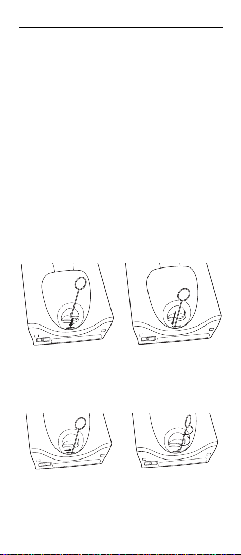
Manual Release of Mobile Computer from Charging Cradle
The Charging cradle, /n PSS-3CR01-00R, contains a
locking mechanism that locks the mobile computer into
the cradle. The mobile computer releases from the
cradle via a software command to the cradle. If the
mobile computer does not have the capability to un-lock
the cradle, un-lock it manually using the optional
dispenser (cradle) key, (p/n PSS-3KY01-00R).
1. Hold the key with hook end pointing to the right.
2. Insert the key straight into the slot, only to the point
where bend stops on the lip of the slot.
3. Slide the key to the right until the handle is centered
in the slot.
4. Rotate the key 90 degrees (1/4 turn)
counterclockwise.
5. Keeping the handle of the key all the way to the right
in the slot, press the key into the slot. The end of the
key should press on a small spring loaded tab within
the cradle.
Page 9

Quick Reference Guide 9
Correct
012345
Incorrect
012345
6. While holding the key down, lift the mobile computer
out of the cradle.
Scanning
To scan bar codes:
1. Launch a scanning application.
2. Press the scan key and aim the mobile computer at a
bar code.
The LED turns red to indicate the scanner is on.
3. Adjust the aim so that the thin, red laser beam covers
the entire length of the bar code.
4. If the decode is successful the LED turns green. The
terminal beeps if programmed accordingly.
Scanning Tips
• For larger bar codes, hold the mobile computer
farther away from the bar code.
• For bar codes with bars that are closer together, hold
the mobile computer closer to the bar code.
• The optimal scanning distance varies with bar code
density, but 10 to 25 cm (4 to 10 inches) generally
works. Practice to determine what distances to work
within.
• Position the scanner at an angle to the bar code. If
the mobile computer is perpendicular to the bar code
being scanned, light can bounce back into the
scanner’s exit window and prevent a successful
decode.
Resetting the Mobile Computer
Warm Boot
A warm boot restarts the mobile computer by closing all
running programs.
Page 10

10 MC17 Mobile Computer
Press and simultaneously hold the Up Arrow and the
Down Arrow keys for 10 seconds and then press the
Scan key. Release the Up Arrow and the Down Arrow
keys. Wait one second and then release the Scan key.
Cold Boot
A cold boot restarts the mobile computer and erases all
user stored records and entries that are not saved in
flash memory (Application and Platform folders). Never
perform a cold boot unless a warm boot does not solve
the problem.
Press and simultaneously hold the Up Arrow and Down
Arrow keys for 10 seconds and then press and hold the
Scan key. Release the Up and Down Arrow keys and
continue to hold the Scan key until the display turns off.
Release the Scan key.
Maintenance
• Protect the mobile computer from temperature
extremes.
• Do not store or use the mobile computer in any
location that is extremely dusty, damp, or wet.
• Use a soft lens cloth to clean the mobile computer. If
the surface of the mobile computer screen becomes
soiled, clean it with a soft cloth moistened with a
diluted window-cleaning solution.
• Periodically replace the rechargeable battery to
ensure maximum battery life and product
performance. Battery life depends on individual
usage patterns. Refer to the MC17 Product
Reference Guide for more information.
• Take care not to scratch the bezel of the mobile
computer. Replacement standard and custom Bezel
Kits are available, p/n KT-098273-XXR.
Bezel Replacement
The plastic bezel can be replaced with a new or
customer specific bezel.
Page 11

Quick Reference Guide 11
1.Place the mobile
computer on a
desktop with the
display facing
down.
2.Using a T6 Torx
drive, remove two
screws securing
the bezel to the
housing.
3.Align the
replacement bezel
on the housing.
4.Using a T6 Torx
drive, secure the bezel to the housing using the two
Tor x sc r e ws .
5. Torque the screws to 2.5 ± 0.2 kgf/cm (2.17 ± 0.17
in-lbs.).
Troubleshooting
Problem Cause Solution
Mobile
computer
does not turn
on.
Rechargeable battery
did not
charge.
Battery not
charged.
Battery not
installed
properly.
The system is
not responding.
Mobile Computer is in a
critical suspend state due
to low battery.
Battery failed. Replace battery. If the mobile
Mobile computer removed
from cradle
while battery
was charging.
Charge or replace the battery.
Install the battery properly.
See Connecting the Battery
on page 4.
Perform a warm boot. If the
mobile computer still does not
turn on, perform a cold boot.
Place the mobile computer in
the Charging cradle. The
mobile computer re-boots and
begins charging.
Depending on how depleted
the battery is, the mobile computer may take up to five minutes before it turns on.
computer still does not operate, perform a warm boot. See
Resetting the Mobile Computer on page 9.
Insert mobile computer in cradle. The battery fully charges
in approximately five hours.
Page 12

12 MC17 Mobile Computer
Problem Cause Solution
Mobile computer shuts
off.
The mobile
computer
does not
accept scan
input.
Battery is
depleted.
Battery is not
connected
properly.
The system is
not responding.
Scanning
application is
not loaded.
Unreadable
bar code.
Distance
between exit
window and
bar code is
incorrect.
Mobile computer is not programmed for
the bar code.
Recharge the battery.
Connect the battery properly.
See Connecting the Battery
on page 4.
Warm boot the mobile computer.
Launch a scanning application
on the mobile computer. See
the system administrator.
Ensure the symbol is not
defaced.
Position the mobile computer
within proper scanning range.
Program the mobile computer
to accept the type of bar code
being scanned. Ensure that
the bar code parameters are
set properly for the bar code
being scanned.
Ergonomic Recommendations
CAUTION In order to avoid or minimize the potential
• Reduce or eliminate repetitive motion
• Maintain a natural position
• Reduce or eliminate excessive force
• Keep objects that are used frequently within easy
reach
• Perform tasks at correct heights
• Reduce or eliminate vibration
• Reduce or eliminate direct pressure
• Provide adjustable workstations
• Provide adequate clearance
• Provide a suitable working environment
• Improve work procedures.
risk of ergonomic injury follow the
recommendations below. Consult with your
local Health & Safety Manager to ensure
that you are adhering to your company’s
safety programs to prevent employee injury.
Page 13

Quick Reference Guide 13
Regulatory Information
All Motorola devices are designed to be compliant with
rules and regulations in locations they are sold and will
be labeled as required.
Local language translations are available at the
following web site:
http://www.motorola.com/enterprisemobility/manuals
This device is approved under the Symbol Technologies
brand; Symbol Technologies, Inc., is the Enterprise
Mobility business of Motorola, Inc. (“Motorola”).
Any changes or modifications to Motorola equipment,
not expressly approved by Motorola, could void the
user's authority to operate the equipment.
CAUTION
Only use Motorola approved and UL Listed
accessories, battery packs and battery
chargers.
Do NOT attempt to charge damp/wet mobile
computers or batteries. All components
must be dry before connecting to an
external power source.
Radio Modules
The device contain approved radio module(s). These
module(s) are identified below.
• WLAN SDIO Radio Module, Model: 21-92955.
Wireless Device Country Approvals
Regulatory markings, subject to certification, are applied
to the device signifying the radio(s) are approved for use
in the following countries: United States, Canada,
Japan, China, S. Korea, Australia and Europe
Please refer to the Motorola Declaration of Conformity
(DoC) for details of other country markings. This is
available at http://www2.symbol.com/doc/.
1
Note
: For 2.4GHz Products: Europe includes, Austria,
Belgium, Bulgaria, Czech Republic, Cyprus, Denmark,
Estonia, Finland, France, Germany, Greece, Hungary,
Iceland, Ireland, Italy, Latvia, Liechtenstein, Lithuania,
Luxembourg, Malta, Netherlands, Norway, Poland,
Portugal, Romania, Slovak Republic, Slovenia, Spain,
Sweden, Switzerland and the United Kingdom.
Operation of the device without regulatory
approval is illegal.
.
1
.
Page 14

14 MC17 Mobile Computer
Country Roaming
This device incorporates the International Roaming
feature (IEEE802.11d) which will ensure the product
operates on the correct channels for the particular
country of use.
Ad-hoc Operation
Ad-Hoc operation is limited to Channels 36-48
(5150-5250 MHz). Use of this band is restricted to
Indoor Use Only, any other use will make the operation
of this device illegal.
Frequency of Operation - FCC and IC
5 GHz Only
The use in the UNII (Unlicensed National Information
Infrastructure) band 1 5150-5250 MHz band is restricted
to Indoor Use Only; any other use will make the
operation of this device illegal.
2.4 GHz Only
The available channels for 802.11 b/g operation in the
US are Channels 1 to 11. The range of channels is
limited by firmware.
Warnings for Use of Wireless Devices
Please observe all warning notices with regard to the
usage of wireless devices.
Pacemakers
Pacemaker manufacturers recommended that a
minimum of 15 cm (6 inches) be maintained between a
handheld wireless device and a pacemaker to avoid
potential interference with the pacemaker. These
recommendations are consistent with independent
research and recommendations by Wireless Technology
Research.
Persons with Pacemakers
• Should ALWAYS keep the device more than 15 cm (6
inches) from their pacemaker when turned ON
• Should not carry the device in a breast pocket
• Should use the ear furthest from the pacemaker to
minimize the potential for interference.
Page 15

Quick Reference Guide 15
• If you have any reason to suspect that interference is
taking place, turn OFF your device.
Other Medical Devices
Please consult your physician or the manufacturer of the
medical device, to determine if the operation of your
wireless product may interfere with the medical device.
RF Exposure Guidelines
Safety Information
Reducing RF Exposure - Use Properly
Only operate the device in accordance with the
instructions supplied.
International
The device complies with Internationally recognized
standards covering human exposure to electromagnetic
fields from radio devices.
EU
Handheld Devices
To comply with EU RF exposure requirements, this
device must be operated in the hand with a minimum
separation distance of 20 cm or more from a person’s
body. Other operating configurations should be avoided.
US and Canada
Co-located statement
To comply with FCC RF exposure compliance
requirement, the antenna used for this transmitter must
not be co-located or operating in conjunction with any
other transmitter/antenna except those already
approved in this filling.
Handheld Devices (that cannot be body worn in a belt clip/holster)
To comply with FCC RF exposure requirements, this
device must be operated in the hand with a minimum
separation distance of 20 cm or more from a person's
body. Other operating configurations should be avoided.
Laser Devices
Complies with 21CFR1040.10 and 1040.11 except for
deviations pursuant to Laser Notice No. 50, dated July
Page 16

16 MC17 Mobile Computer
COMPLIES WITH 21CFR1040.10 AND 1040.11 EXCEPT FOR DEVIATIONS
PURSUANT TO LASER NOTICE No. 50, DATED JULY 26, 2001, AND
EN60825-1:1994+A1:2002+A2:2001, IEC60825-1:1993+A1:1997+A2:2001.
26, 2001, and with EN60825-1:1994+A1:2002+A2:2001
and IEC60825-1:1993+A1:1997+A2:2001.
The laser classification is marked on one of the labels
on the device.
Class 1 Laser devices are not considered to be
hazardous when used for their intended purpose. The
following statement is required to comply with US and
international regulations:
Caution: Use of controls, adjustments or performance of
procedures other than those specified herein may result
in hazardous laser light exposure.
Class 2 laser scanners use a low power, visible light
diode. As with any very bright light source, such as the
sun, the user should avoid staring directly into the light
beam. Momentary exposure to a Class 2 laser is not
known to be harmful.
Scanner Labeling
Power Supply
Use only a Motorola approved power supply output
rated at 12 VDC and minimum 9 A. The power supply
shall be Listed to UL/CSA 60950-1; and certified to
IEC60950-1 and EN60950-1 with SELV outputs. Use of
alternative power supply will invalidate any approval
given to this device and may be dangerous.
Taiwan - Recycling
EPA (Environmental Protection
Administration) requires dry battery
producing or importing firms in
accordance with Article 15 of the
Waste Disposal Act are required to indicate the
recycling marks on the batteries used in sales, giveaway
or promotion. Contact a qualified Taiwanese recycler for
proper battery disposal.
Page 17

Quick Reference Guide 17
Radio Frequency Interference Requirements-FCC
Note: This equipment has been tested
and found to comply with the limits for a
15 of the FCC rules. These limits are designed to
provide reasonable protection against harmful
interference in a residential installation. This equipment
generates, uses and can radiate radio frequency energy
and, if not installed and used in accordance with the
instructions, may cause harmful interference to radio
communications. However there is no guarantee that
interference will not occur in a particular installation. If
this equipment does cause harmful interference to radio
or television reception, which can be determined by
turning the equipment off and on, the user is
encouraged to try to correct the interference by one or
more of the following measures:
• Reorient or relocate the receiving antenna
• Increase the separation between the equipment and
receiver
• Connect the equipment into an outlet on a circuit
different from that to which the receiver is connected
• Consult the dealer or an experienced radio/TV
technician for help.
Radio Transmitters (Part 15)
This device complies with Part 15 of the FCC Rules.
Operation is subject to the following two conditions: (1)
this device may not cause harmful interference, and (2)
this device must accept any interference received,
including interference that may cause undesired
operation.
Radio Frequency Interference Requirements - Canada
This Class B digital apparatus complies with Canadian
ICES-003. Cet appareil numérique de la classe B est
conforme à la norme NMB-003 du Canada.
Radio Transmitters
This device complies with RSS 210 of Industry &
Science Canada. Operation is subject to the following
two conditions: (1) this device may not cause harmful
interference and (2) this device must accept any
interference received, including interference that may
cause undesired operation.
Class B digital device, pursuant to Part
Page 18

18 MC17 Mobile Computer
Label Marking: The Term “IC:” before the radio
certification only signifies that Industry Canada technical
specifications were met.
For RLAN Devices
The use of 5 GHz RLAN’s, for use in Canada, have the
following restrictions:
• Restricted Band 5.60 – 5.65 GHz
Marking and European Economic
Area (EEA)
The use of 2.4GHz RLAN's, for use through the EEA,
have the following restrictions:
• Maximum radiated transmit power of 100 mW EIRP
in the frequency range 2.400 -2.4835 GHz
• France, outside usage is restricted to 2.4 - 2.454
GHz.
• Italy requires a user license for outside usage.
Statement of Compliance
Motorola, Inc., hereby, declares that this device is in
compliance with the essential requirements and other
relevant provisions of Directives 1999/5/EC,
89/336/EEC and 73/23/EEC. Declaration of
Conformities may be obtained from
http://www2.symbol.com/doc/.
Japan (VCCI) - Voluntary Control Council for Interference
この装置は、情報処理装置等電波障害自主規制協議会
(VCCI)の基準に基づくクラス B 情報技術装置で
す。この装置は、家庭環境で使用することを目的とし
ていますが、この装置がラジオやテレビジョン受信機
に近接して使用されると、受信障害を引き起こすこと
があります。 取扱説明書に従って正しい取り扱いをし
て下さい。
This is a Class B product based on the standard of the
Voluntary Control Council for Interference from
Information Technology Equipment (VCCI). If this is
used near a radio or television receiver in a domestic
environment, it may cause radio interference. Install and
use the equipment according to the instruction manual.
Page 19

Quick Reference Guide 19
Other Countries
Australia
Use of 5GHz RLAN’s in Australia is restricted in the
following band 5.50 – 5.65GHz.
Brazil
Declarações Regulamentares para MC1770 / MC1790.
Nota: "A marca de certificação se aplica ao Transceptor,
modelo MC1770 / MC1790. Este equipamento opera
em carácter secundário, isto é, não tem direito a
proteção contra interferência prejudicial, mesmo de
estações do mesmo tipo, e não pode causar
interferência a sistemas operando em carácter primário.
Mexico - Restrict Frequency Range to: 2.450 - 2.4835
GHz.
Taiwan - 臺灣
低功率電波輻射性電機管理辦法
第十二條
經型式認證合格之低功率射頻電機,非經許可,公司、商號
或使用者均不得擅自變更頻率、加大功率或變更原設計之特
性及功能。
第十四條
低功率射頻電機之使用不得影響飛航安全及干擾合法通信;
經發現有干擾現象時,應立即停用,並改善至無干擾時方得
繼續使用。
前項合法通信,指依電信規定作業之無線電通信。
低功率射頻電機須忍受合法通信或工業、科學及醫療用電波
輻射性電機設備之干擾。
限制頻率範圍是: 2.400 - 2.4835 GHz。 最大發射功率 :27 dBm
5.250 - 5.350 GHz。 最大發射功率 :17 dBm
5.725 - 5.850 GHz。 最大發射功率 :24 dBm
2.4GHz: 11 個通道
5 GHz: 8 個通道
Korea
당해 무선설비는 운용 중 전파혼신 가능성이 있음
당해 무선설비 는전파혼 신 가능성이 있으므로
인명안전과 관련된 서비스는 할 수 없습니다 .
Battery Information
Motorola rechargeable battery packs are designed and
constructed to the highest standards within the industry.
Page 20

20 MC17 Mobile Computer
However, there are limitations to how long a battery can
operate or be stored before needing replacement. Many
factors affect the actual life cycle of a battery pack, such
as heat, cold, harsh environmental conditions and
severe drops.
When batteries are stored over six (6) months, some
irreversible deterioration in overall battery quality may
occur. Store batteries discharged in a dry, cool place,
removed from the equipment to prevent loss of capacity,
rusting of metallic parts and electrolyte leakage. When
storing batteries for one year or longer, they should be
charged and discharged at least once a year. If an
electrolyte leakage is observed, avoid any contact with
affected area and properly dispose of the battery.
Batteries must be charged within the 32° to 104° F (0° to
+40° C) ambient temperature range.
Replace the battery when a significant loss of run time is
detected.
Standard warranty period for all Motorola batteries is
one year, regardless if the battery was purchased
separately or included as part of the mobile computer.
For more information on Motorola batteries, please visit:
http:/mysymbolcare.symbol.com/battery/batbasics1.htm
l
Battery Pack Information
This device is equipped with a removable and
rechargeable Lithium polymer battery. When a
replacement is needed, please request the dealer from
whom your device was purchased to assist you. Use
only manufacturer approved batteries.
Battery Pack Reminders
• The area in which the units are charged should be
clear of debris and combustible materials or
chemicals. Particular care should be taken where the
device is charged in a non commercial environment.
• Follow battery usage, storage, and charging
guidelines found in the user's guide.
• Improper battery use may result in a fire, explosion,
or other hazard.
• To charge the mobile device battery, the battery and
charger temperatures must be between +32 ºF and
+104 ºF (0 ºC and +40 ºC)
Page 21

Quick Reference Guide 21
• Do not use incompatible batteries and chargers. Use
of an incompatible battery or charger may present a
risk of fire, explosion, leakage, or other hazard. If you
have any questions about the compatibility of a
battery or a charger, contact Motorola Enterprise
Mobility support.
• Do not disassemble or open, crush, bend or deform,
puncture, or shred.
• Severe impact from dropping any battery-operated
device on a hard surface could cause the battery to
overheat.
• Do not short circuit a battery or allow metallic or
conductive objects to contact the battery terminals.
• Do not modify or remanufacture, attempt to insert
foreign objects into the battery, immerse or expose to
water or other liquids, or expose to fire, explosion, or
other hazard.
• Do not leave or store the equipment in or near areas
that might get very hot, such as in a parked vehicle or
near a radiator or other heat source. Do not place
battery into a microwave oven or dryer.
• Battery usage by children should be supervised.
• Please follow local regulations to promptly dispose of
used re-chargeable batteries.
• Do not dispose of batteries in fire.
• Seek medical advice immediately if a battery has
been swallowed.
• In the event of a battery leak, do not allow the liquid
to come in contact with the skin or eyes. If contact
has been made, wash the affected area with large
amounts of water and seek medical advice.
• If you suspect damage to your equipment or battery,
contact Motorola Enterprise Mobility support to
arrange for inspection.
Use with Hearing Aids
When some wireless devices are used near some
hearing devices (hearing aids and cochlear implants),
users may detect a buzzing, humming, or whining noise.
Some hearing devices are more immune than others to
this interference noise, and wireless devices also vary in
the amount of interference they generate. In the event of
interference you may want to consult your hearing aid
supplier to discuss solutions.
Page 22

22 MC17 Mobile Computer
Waste Electrical and Electronic
Equipment (WEEE)
English: For EU Customers: All products at the end of their
life must be returned to Motorola for recycling. For
information on how to return product, please go to:
http://www.motorola.com/recycle/weee.
Français: Clients de l'Union Européenne : Tous les produits
en fin de cycle de vie doivent être retournés à Motorola pour
recyclage. Pour de plus amples informations sur le retour de
produits, consultez : http://www.motorola.com/recycle/weee.
Español: Para clientes en la Unión Europea: todos los
productos deberán entregarse a Motorola al final de su ciclo
de vida para que sean reciclados. Si desea más información
sobre cómo devolver un producto, visite:
http://www.motorola.com/recycle/weee.
Deutsch: Für Kunden innerhalb der EU: Alle Produkte
müssen am Ende ihrer Lebensdauer zum Recycling an
Motorola zurückgesandt werden. Informationen zur
Rücksendung von Produkten finden Sie unter
http://www.motorola.com/recycle/weee.
Italiano: per i clienti dell'UE: tutti i prodotti che sono giunti al
termine del rispettivo ciclo di vita devono essere restituiti a
Motorola al fine di consentirne il riciclaggio. Per informazioni
sulle modalità di restituzione, visitare il seguente sito Web:
http://www.motorola.com/recycle/weee.
Português: Para clientes da UE: todos os produtos no fim
de vida devem ser devolvidos à Motorola para reciclagem.
Para obter informações sobre como devolver o produto,
visite: http://www.motorola.com/recycle/weee.
Nederlands: Voor klanten in de EU: alle producten dienen
aan het einde van hun levensduur naar Motorola te worden
teruggezonden voor recycling. Raadpleeg
http://www.motorola.com/recyc le/weee voor meer informatie
over het terugzenden van producten.
Polski: Klienci z obszaru Unii Europejskiej: Produkty
wycofane z eksploatacji nale¿y zwróciæ do firmy Motorola w
celu ich utylizacji. Informacje na temat zwrotu produktów
znajduj¹ siê na stronie internetowej
http://www.motorola.com/recycle/weee.
Čeština: Pro zákazníky z EU: Všechny produkty je nutné po
skonèení jejich životnosti vrátit spoleènosti Motorola
k recyklaci. Informace o zpùsobu vrácení produktu najdete
na webové stránce: http://www.motorola.com/recycle/weee.
Eesti: EL klientidele: kõik tooted tuleb nende eluea lõppedes
tagastada taaskasutamise eesmärgil Motorola'ile.
Lisainformatsiooni saamiseks toote tagastamise kohta
külastage palun aadressi:
http://www.motorola.com/recycle/weee.
Page 23

Quick Reference Guide 23
Magyar: Az EU-ban vásárlóknak: Minden tönkrement
terméket a Motorola vállalathoz kell eljuttatni
újrahasznosítás céljából. A termék visszajuttatásának
módjával kapcsolatos tudnivalókért látogasson el a
http://www.motorola.com/recycle/weee weboldalra.
Slovenski: Za kupce v EU: vsi izdelki se morajo po poteku
življenjske dobe vrniti podjetju Motorola za reciklažo. Za
informacije o vraèilu izdelka obišèite:
http://www.motorola.com/recycle/weee.
Svenska: För kunder inom EU: Alla produkter som uppnått sin
livslängd måste returneras till Motorola för återvinning.
Information om hur du returnerar produkten finns på
http://www.motorola.com/recycle/weee.
Suomi: Asiakkaat Euroopan unionin alueella: Kaikki tuotteet
on palautettava kierrätettäväksi Motorola-yhtiöön, kun
tuotetta ei enää käytetä. Lisätietoja tuotteen palauttamisesta
on osoitteessa http://www.motorola.com/recycle/weee.
Dansk: Til kunder i EU: Alle produkter skal returneres til
Motorola til recirkulering, når de er udtjent. Læs
oplysningerne om returnering af produkter på:
http://www.motorola.com/recycle/weee.
Ελληνικά: Για πελάτες στην Ε.Ε.: Όλα τα προϊόντα, στο
τέλος της διάρκειας ζωής τους, πρέπει να επιστρέφονται
στην Motorola για ανακύκλωση. Για περισσότερες
πληροφορίες σχετικά με την επιστροφή ενός προϊόντος,
επισκεφθείτε τη διεύθυνση
http://www.motorola.com/recycle/weee στο Διαδίκτυο.
Malti: Għal klijenti fl-UE: il-prodotti kollha li jkunu waslu
fl-aħħar tal-ħajja ta' l-użu tagħhom, iridu jiġu rritornati għand
Motorola għar-riċiklaġġ. Għal aktar tagħrif dwar kif għandek
tirritorna l-prodott, jekk jogħġbok żur:
http://www.motorola.com/recycle/weee.
Slovenski: Za kupce v EU: vsi izdelki se morajo po poteku
življenjske dobe vrniti podjetju Motorola za reciklažo. Za
informacije o vračilu izdelka obiščite:
http://www.motorola.com/recycle/weee.
Slovenčina: Pre zákazníkov z krajín EU: Všetky výrobky
musia byť po uplynutí doby ich životnosti vrátené spoločnosti
Motorola na recykláciu. Bližšie informácie o vrátení výrobkov
nájdete na: http://www.motorola.com/recycle/weee.
Lietuvių: ES vartotojams: visi gaminiai, pasibaigus jų
eksploatacijos laikui, turi būti grąžinti utilizuoti į kompaniją
„Motorola“. Daugiau informacijos, kaip grąžinti gaminį, rasite:
http://www.motorola.com/recycle/weee.
Latviešu: ES klientiem: visi produkti pēc to kalpošanas
mūža beigām ir jānogādā atpakaļ Motorola otrreizējai
pārstrādei. Lai iegūtu informāciju par produktu nogādāšanu
Motorola, lūdzu, skatiet:
http://www.motorola.com/recycle/weee.
Page 24

Motorola, Inc.
One Motorola Plaza
Holtsville, New York 11742, USA
1-800-927-9626
http://www.motorola.com/enterprisemobility
MOTOROLA and the Stylized M Logo and Symbol and the Symbol logo are
registered in the U.S. Patent and Trademark Office. All other product or
service names are the property of their registered owners.
© Motorola, Inc. 2008
72-100298-03 Revision A - July 2008
Service Information
If you have a problem using the equipment, contact your
facility’s Technical or Systems Support.
If there is a problem with the equipment, they will contact
Motorola Enterprise Mobility support for your region.
Contact information is available at:
http://www.motorola.com/enterprisemobility/contactsupport.
For the latest version of this guide go to:
http://www.motorola.com/enterprisemobility/manuals.
 Loading...