

Page 1
LS 2106 RS-232/Synapse/Keyboard Wedge Scanner
Product Reference Guide
Click on red text at any location in the manual to jump to the
specified chapter, topic, or reference.
About This Manual
Table of Contents
Glossary
Copyright
70-32821-01
Revision B
February, 1998
Page 2

Contents
About This Guide
Notational Conventions
Related Publications
Service Information
Symbol Support Center
Canada
Europe
Asia
Chapter 1. Setting Up the LS 2106
I
ntroduction
Audience
Unpacking
Setting Up the LS 2106
Installing the Cable
Switching Cables
Connecting to a Host
Chapter 2. Scanning with the LS 2106
Introduction
Scanning with the LS 2106
Aiming the Scanner
LS 2106 Decode Zone
Chapter 3. Maintenance and Specifications
Introduction
Maintenance
Troubleshooting
v
Page 3

LS 2106 Product Reference Guide
Accessories
Standard Accessories
Cables
Optional Accessories
Technical Specifications
LS 2106 Signal Descriptions
Beeper Indications
Chapter 4. Parameter Menus
Introduction
Default Parameters
Set Default Parameter
Beeper Volume
Laser On Time
Power Mode
Beep After Good Decode
Do Not Beep After Good Decode
Transmit “No Read” Message
Do Not Transmit “No Read” Message
Decode Redundancy
Autodiscriminate Response Time
Enable/Disable UPC-E/UPC-A
Enable/Disable EAN-8/EAN-13
Enable/Disable Bookland EAN
Decode UPC/EAN Supplementals
Transmit UPC-A/UPC-E Check Digit
UPC-A Preamble
UPC-E Preamble
Convert UPC-E to UPC-A
EAN Zero Extend
EAN Zero Extend Code Type
Enable/Disable Code 128
Enable/Disable UCC/EAN-128
Enable/Disable Code 39
Code 39 Check Digit Verification
Transmit Code 39 Check Digit
Do Not Transmit Code 39 Check Digit
Enable/Disable Code 39 Full ASCII
Code 39 Buffering (Scan & Store)
Buffer Data
Clear Transmission Buffer
Transmit Buffer
Overfilling Transmission Buffer
vi
Page 4

Attempt to Transmit an Empty Buffer
Enable/Disable Code 93
Enable/Disable Interleaved 2 of 5
Set Lengths for Interleaved 2 of 5
Convert I 2 of 5 to EAN-13
Enable/Disable Discrete 2 of 5
Set Lengths for Discrete 2 of 5
Enable/Disable Codabar
CLSI Editing
NOTIS Editing
Enable/Disable MSI Plessey
MSI Plessey Check Digits
Transmit MSI Plessey Check Digit
Do Not Transmit MSI Plessey Check Digit
MSI Plessey Check Digit Algorithm
Transmit Code ID Character
Transmit Code ID Character
Prefix/Suffix Values
Scan Data Transmission Format
Host Interfaces
National Keyboard Types
Fast Transmit
Intercharacter Delay
Numeric Bar Codes
Cancel
Keyboard Maps
Contents
ASCII Character Set A-1
vii
Page 5

About This Guide
The
LS 2106 Product Reference Guide
operation, troubleshooting, and maintenance of the LS 2106 scanner.
Notational Conventions
The following conventions are used in this document:
t
Bullets (•) indicate:
s
action items
s
lists of alternatives
s
lists of required steps that are not necessarily sequential
t
Sequential lists (e.g., those that describe step-by-step procedures) appear as
numbered lists.
Related Publications
provides general instructions for setup, programming,
LS 2100 Series Quick Reference Guide
t
LS 2100 Product Reference Guide
t
LS 2104 Product Reference Guide
t
p/n 70-32817-xx
p/n 70-32818-xx
p/n 70-32820-xx
Service Information
If you have a problem with your equipment, contact the Symbol Support Center. Before
calling, have the model number , serial number, and several of your bar code symbols at hand.
Call the Support Center from a phone near the scanning equipment so that the service person
can try to talk you through your problem. If the equipment is found to be working properly
and the problem is symbol readability, the Support Center will request samples of your bar
codes for analysis at our plant.
ix
Page 6

Chapter 1
Setting Up the LS 2106
Introduction
The LS 2106 hand-held laser scanner offers excellent performance in retail and light
industrial applications. Advanced ergonomic design ensures comfortable use for extended
periods of time.
The LS 2100 Series hand-held scanner is based on the SE 1200 Series scan engine, mylar®
scan element and the Visible Laser Diode (VLD). This state of the art technology gives the
scanner a wider decode zone, greater depth of field, and a visible scan beam. This model reads
color bar codes and symbols printed on all substrates. See the
2-4.
LS 2106 Decode Zone
on page
Figure 1-1. LS 2106 Scanner
Here’s what each member of the LS 2100 family offers you:
t
LS 2100 - The aggressiveness of this discrete scanner is typical of the
LS 2100 family’s performance. It connects easily to, and is programmed by, the
1-1
Page 7

LS 2106 Product Reference Guide
complete line of Symbol Technologies portable terminals and the full range of
Symbol and OmniLink
t
LS 2104 - With a simple cable change, this scanner is compatible with:
s
RS 232C asynchronous terminals
s
Synapse
s
s
s
s
t
LS 2106 - The LS 2106 scanner is a keyboard “wedge” interface which adds efficient,
reliable bar code reading to your PS/2 or A T/XT terminal. Since entered scan data is
transmitted as keystrokes, no software changes to the host system are necessary . The
scanner contains on-board discrete keyboard wedge communications for connecting
to asynchronous terminals and host systems. It can also accommodate any of the
Synapse™ “Smart Cables” which allows you to connect to a wide variety of host
systems. Some installations require one cable; others require additional adapters
between the keyboard, the PC, and the y-cable.
All of the LS 2100 series scan automatically at the rate of 36 scans per second. For decode
capability, see
TM
“Smart Cables”, which allow you to connect to:
Wand Emulation terminals
IBM 4683/4, 4693/4 series of terminals
All leading OCIA terminals, including NCR, Nixdorf, and ICL terminals.
Dual RS-232 Hosts
Popular OCR terminals, such as Fujitsu and ICL.
Technical Specifications
TM
interface controllers.
on page 3-3.
Audience
The intended audience for this manual is personnel performing installation/setup and
programming of LS 2106 scanners.
Unpacking
Remove the LS 2106 from its packing and inspect it for damage. If the scanner was damaged
in transit, call the Symbol Support Center at one of the telephone numbers listed on page x.
KEEP THE PACKING
need to return your equipment for servicing.
1-2
. It is the approved shipping container and should be used if you ever
Page 8
Setting Up the LS 2106
Setting Up the LS 2106
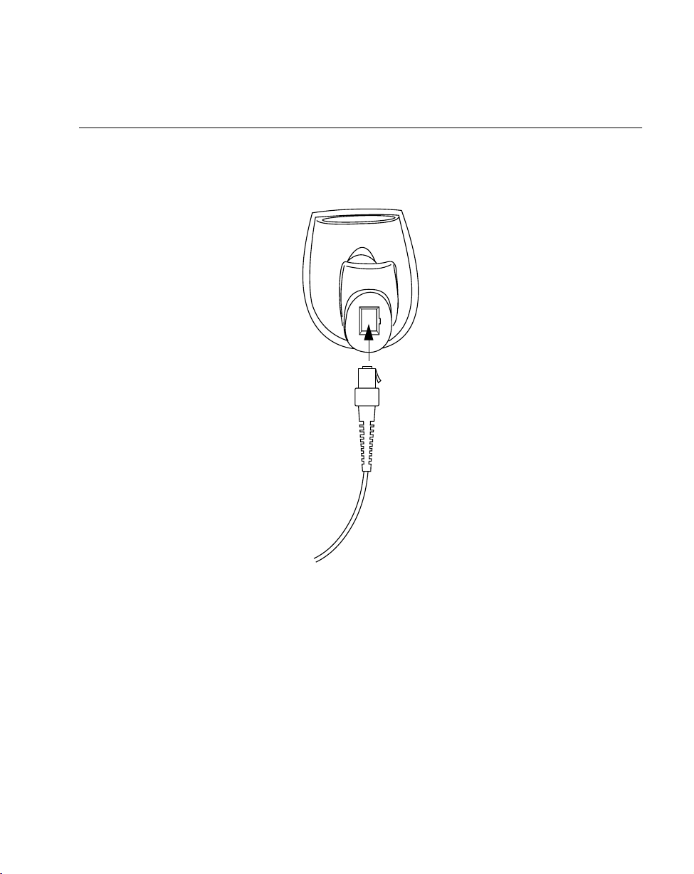
Installing the Cable
Insert the cable into the receptable on the bottom of the scanner, as shown below:
Figure 1-2. Installing the Cable
Switching Cables
Different cables are required for different hosts. To change the scanner cable:
1. Press the tab on the cable with a small screwdriver.
2. Pull the cable out of the receptacle on the bottom of the scanner.
3. Insert a new cable in the receptacle. Press the cable into the receptacle until you hear
a click.
1-3
Page 9
LS 2106 Product Reference Guide
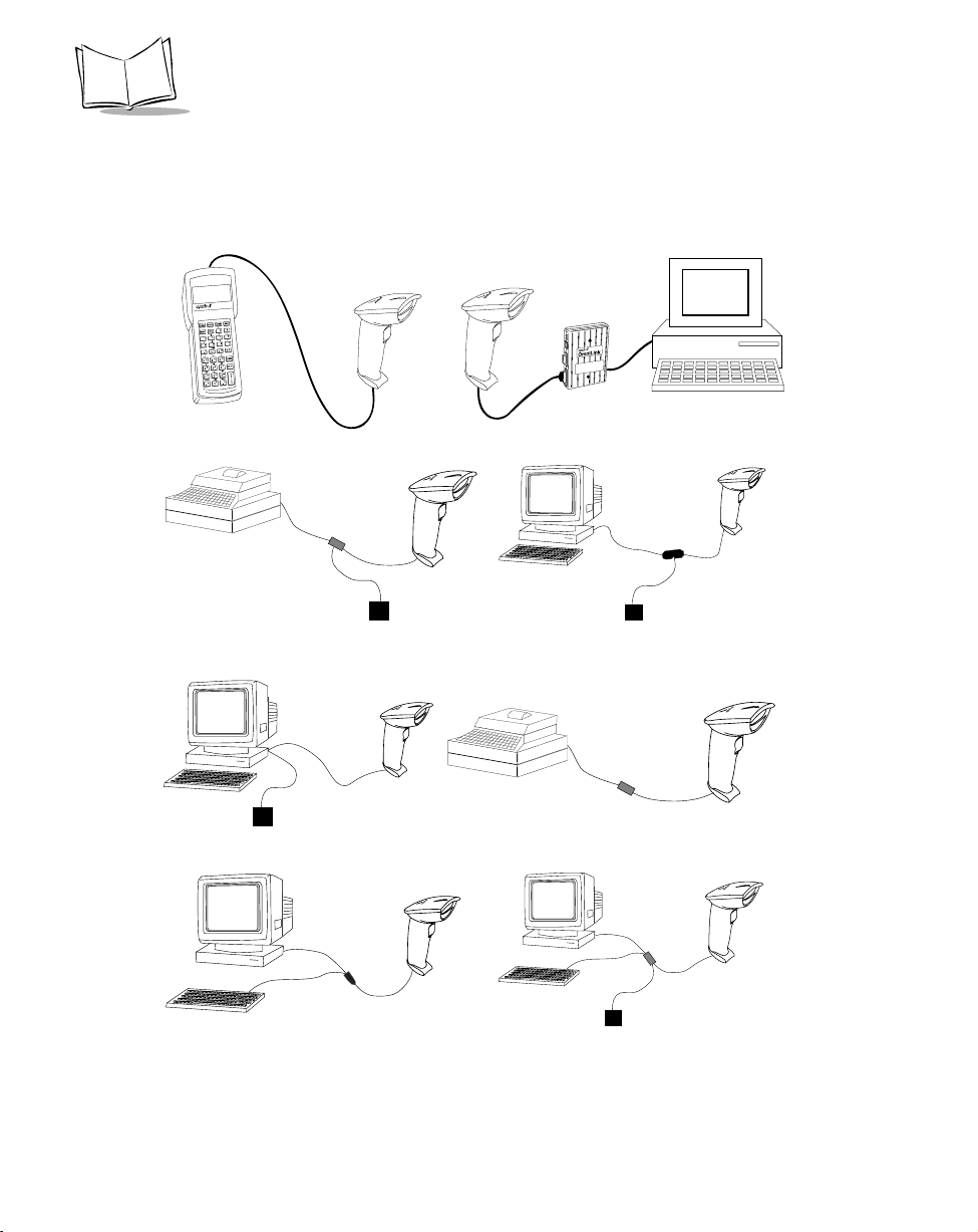
Connecting to a Host
Plug the connector at the end of the LS 2106 cable into the appropriate port on the Symbol
interface controller or portable terminal. Refer to the controller user documentation for full
details.
LS 2106
LS 2106
Host
PDT
Connecting to a PDT
Host
Synapse
Smart
Cable
OCIA via Synapse
Host
Power Supply
(As Required)
Direct RS-232 Connection
Host
LS 2106
Synapse
Adapter
Cable
LS 2106
LS 2106
Power
Supply
(As Required)
IBM 4683/84/93/94 C
Cash Register
Controller
Host Connection through a Controller
Host LS 2106
Synapse
Smart
Cable
Synapse
Adapter
Synapse
Adapter
Cable
Cable
CablePower Supply
LS 2106
(As Req’d_
RS-232 via Synapse Adapter Cable
Synapse
Smart
Cable
IBM via Synapse Adapter Cable
Host LS 2106
Synapse
Smart
1-4
Keyboard W edge
Keyboard Wedge via Synapse
Figure 1-3. Connecting to a Host
Power Supply
(As Required)
Page 10

Chapter 2
Scanning with the LS 2106
Introduction
This chapter covers the proper techniques for scanning bar codes and the decode zone for the
LS 2106 scanner.
Scanning with the LS 2106
Before you can use the scanner , it should have already been installed and programmed. If not,
refer to Chapter 4,
need assistance, contact your local supplier or Symbol Techologies.
1. Before you use the scanner, make sure all cable connections are secure.
2. Make sure the bar code is in the correct scanning range. Aim and press the trigger;
the scan beam lights and an orange light illuminates at the rear of the scanner. The
scanner has read the symbol when:
s
You hear a beep.
s
The orange light turns green.
s
The laser turns off.
Parameter Menus
for instructions on programming your scanner. If you
2-1
Page 11
LS 2106 Product Reference Guide
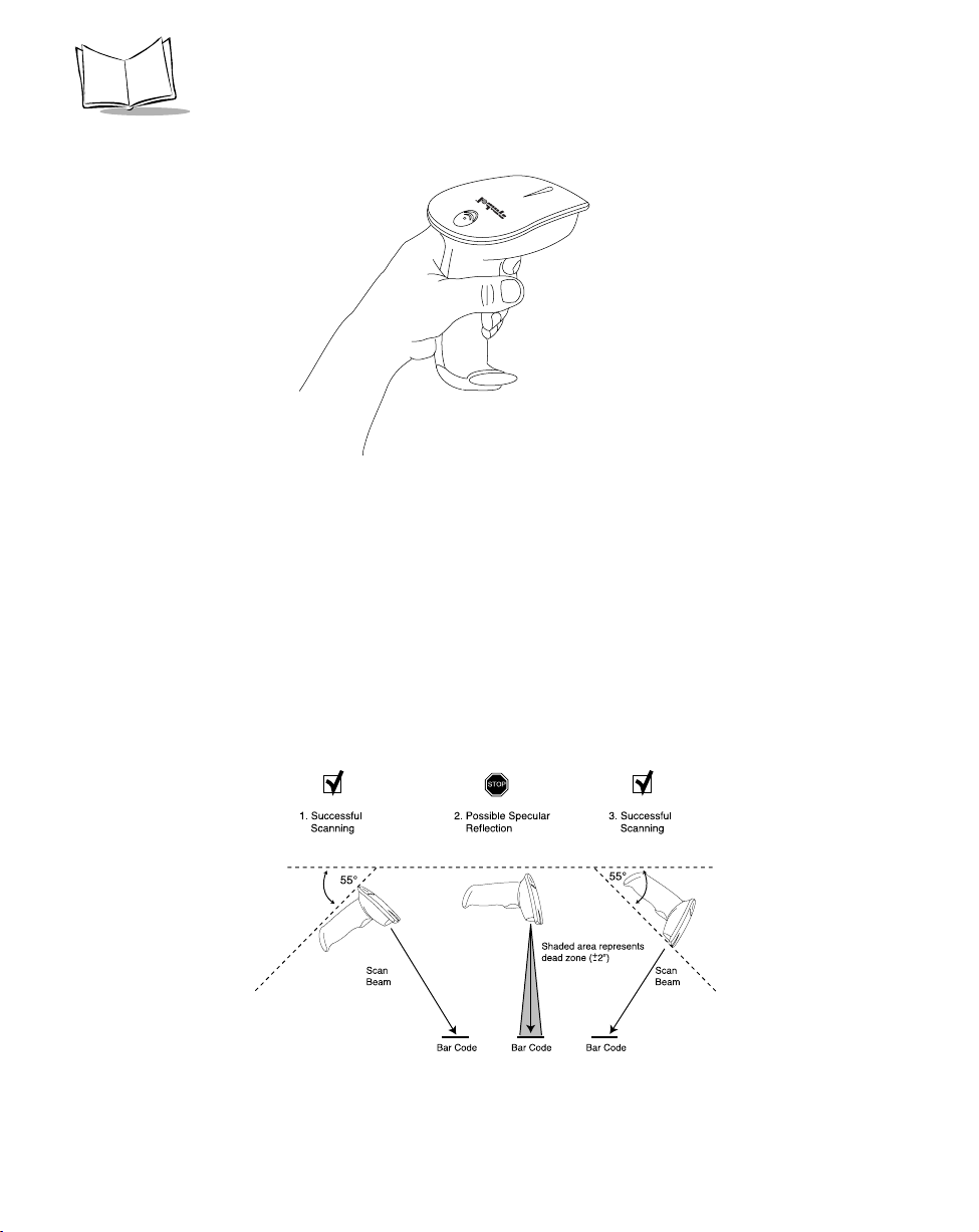
Figure 2-1. Holding the Scanner
Aiming the Scanner
Hold the scanner at an angle. Do not hold the scanner directly over the bar code. Laser light
reflecting directly back into the scanner from the bar code is known as specular reflection.
This strong light can “blind” the scanner and make decoding difficult. The area where
specular reflection occurs is known as a “dead zone”.
You can tilt the scanner up to 55° forward or back and achieve a successful decode. Simple
practice quickly shows what tolerances to work within.
2-2
Page 12
Scanning with the LS 2106
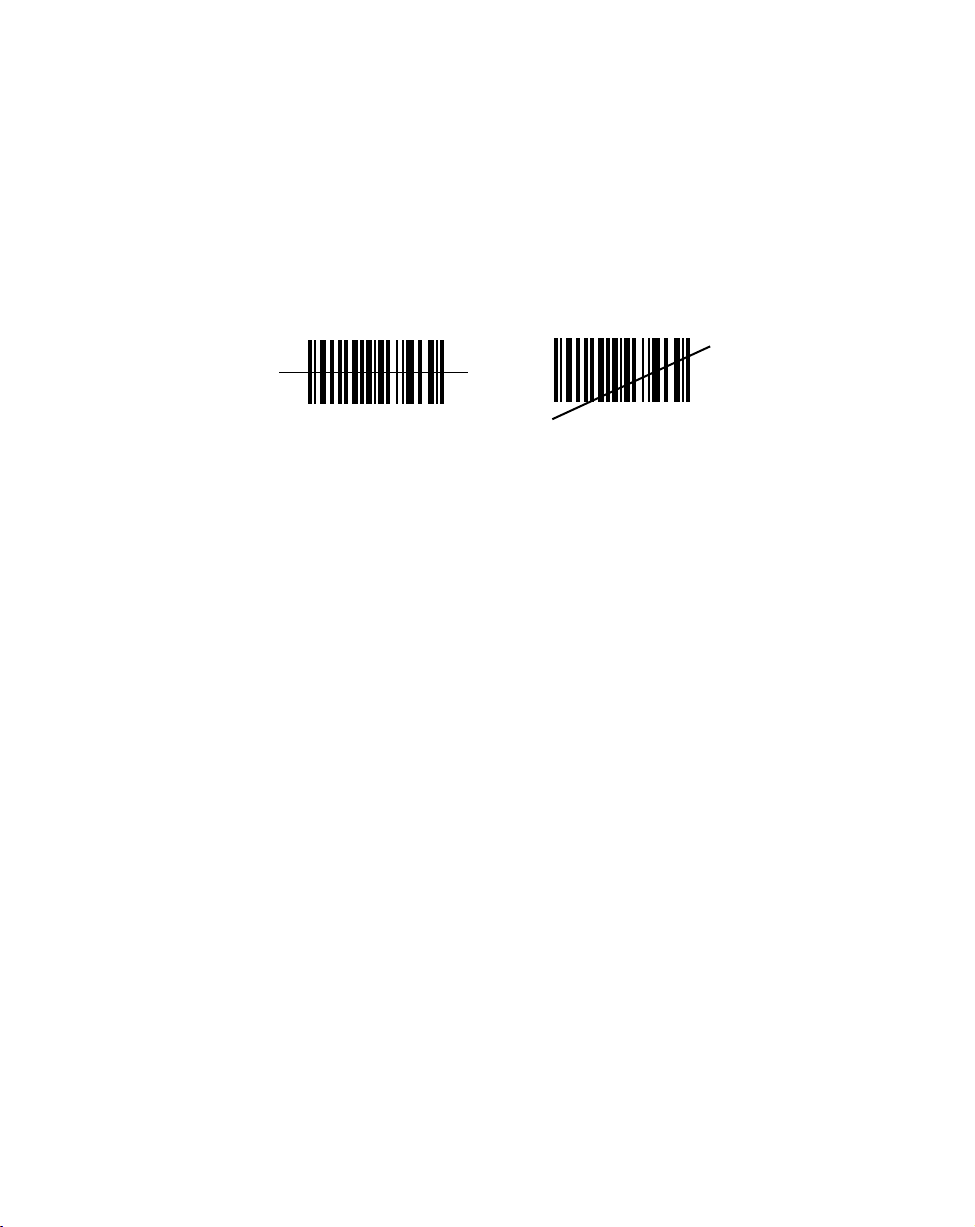
t Scan the Entire Symbol
s The scan beam must cross every bar and space on the symbol (as in the left bar
code below).
s The larger the symbol, the farther away you should hold the scanner.
s Hold the scanner closer for symbols with bars that are close together.
Right Wrong
012345
012345
What Does The Beep Mean?
When you hear 1 beep (short high tone) it means data has been decoded successfully. If any
other beeps are heard, contact the technical person in charge of scanning.
When the symbol has been successfully decoded, you will hear a short, high-tone beep, and
the green decode LED will light.
For more specific information on the meanings of the various beeper sounds, refer to Beeper
Indications on page 3-7.
2-3
Page 13
LS 2106 Product Reference Guide
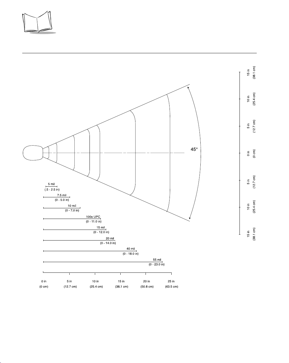
LS 2106 Decode Zone
2-4
Page 14

Chapter 3
Maintenance and Specifications
Introduction
This chapter covers the appropriate methods for maintaining and the technical specifications
for the scanner.
Maintenance
Cleaning the exit window is the only maintenance required. A dirty window may affect
scanning accuracy.
t Do not allow any abrasive material to touch the window.
t Remove any dirt particles with a damp cloth.
t Wipe the window using a tissue moistened with ammonia/water.
t Do not spray water or other cleaning liquids directly into the window.
t Do not remove the nose of the scanner.
Troubleshooting
If, after following the operating instructions, the scanner does not work:
t Check the system power.
t Make sure the controller is programmed to decode bar codes of the symbology you
are scanning.
t Check for loose cable connections.
3-1
Page 15

LS 2106 Product Reference Guide
t Make sure the symbol is not defaced.
t Try scanning test symbols of the same code type.
If after performing these checks the symbol still does not scan, contact your distributor or call
the Symbol Support Center. See page x for the telephone number.
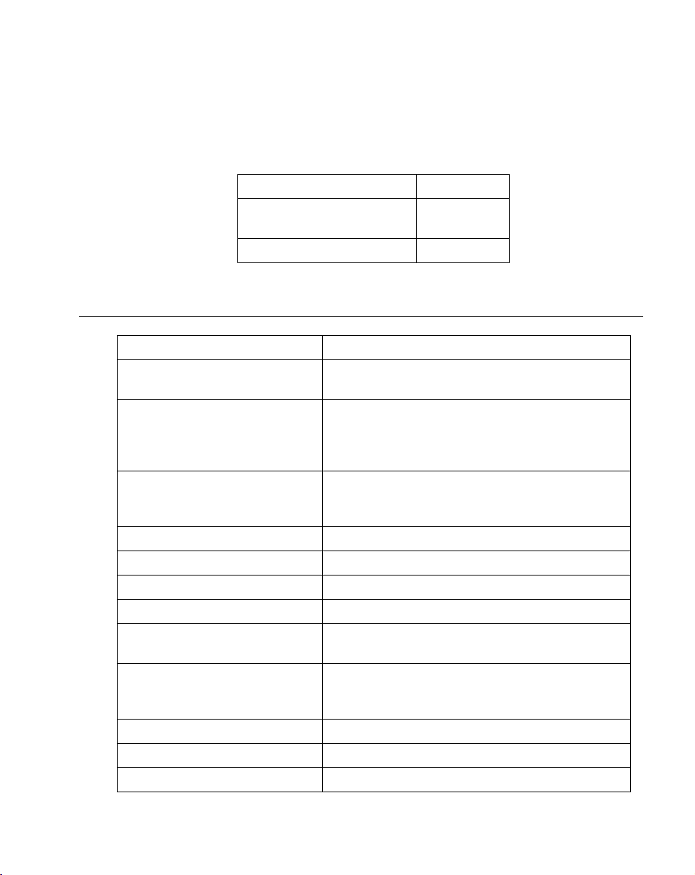
Accessories
Standard Accessories:
Description Part Number
Cables
LS 2100 Series Quick
Reference Guide
LS 2106 Product
Reference Guide
Shipping Box 50-01400-184
Description Part Number
PS/2 “Y” Scanner Cable 25-31828-01
PS/2 to AT/XT Adapter Connectors KT-32903-01(Set)
IBM SureOne PS2 Cable 25-17359-01
Synapse Adapter Cable 25-31617-01
110V Power Supply 50-14000-008
220/240V Power Supply 50-14000-009
70-32817-xx
70-32821-xx
3-2
Page 16
Maintenance and Specifications
Optional Accessories
Optional accessories, supplied at extra cost, include additional units of any item listed above
and the following items:
Description Part Number
Hands-Free Stand-free
standing
Desk-Mount Stand 21-33323-01
21-33324-01
Technical Specifications
Item Description
Power Requirements 4.75 to 5.25 VDC; 180 mA @ 5 VDC Typical
Low Power: 20µ maximum
Decode Capability UPC/EAN,UPC/EAN with supplementals, UCC/EAN
128, Code 39 Full ASCII, Code 128, Codabar,
Interleaved 2 of 5, Discrete 2 of 5, Code 93, MSI/
Plessey.
Decode Depth of Field Maximum typical working distance is 11.0 in. (100%
UPC/EAN); minimum element width resolution is 5.5
mils
Scan Repetition Rate Approximately 36 scans/sec (bidirectional)
Skew Tolerance ± 55˚ min. (from normal)
Pitch Tolerance ± 50° (from normal)
Yaw ± 35° at 6 in. on 100% UPC/EAN
Print Contrast Minimum 20% minimum reflectance differential, measured at
675 nm.
Ambient Light Immunity Immune to direct exposure to normal office and
factory lighting conditions, as well as direct exposure
to sunlight.
Durability 5 ft (152 cm) drops to concrete
Operating Temperature 32° to 104°F (0° to 40°C)
Storage Temperature -40˚ to 140˚ (-40˚ to 60°C)
3-3
Page 17
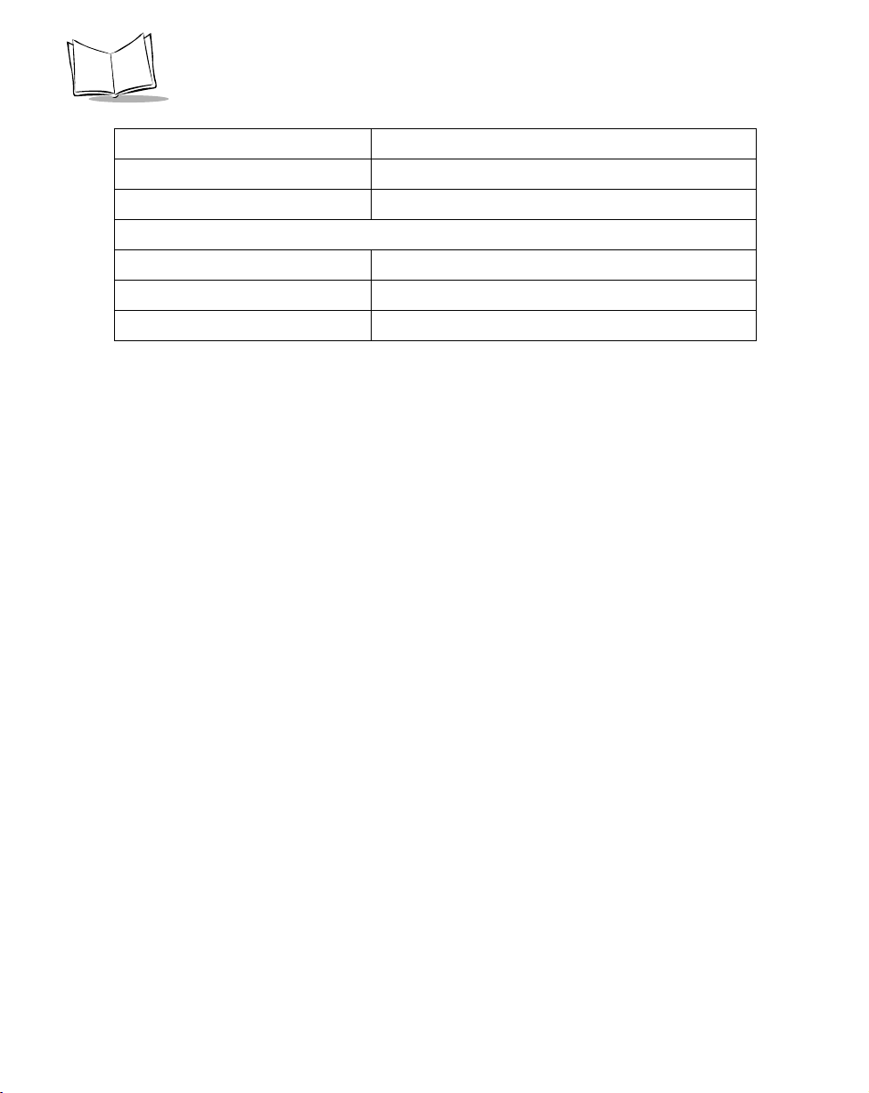
LS 2106 Product Reference Guide
Item Description
Straight Cable Length 6 ft (183 cm)
Weight (without cable) 5.5 oz. (170 gm)
Dimensions:
Height 6.7 in (167 mm)
Width 2.8 in (70 mm)
Depth 3.4 in (85 mm)
3-4
Page 18

Maintenance and Specifications
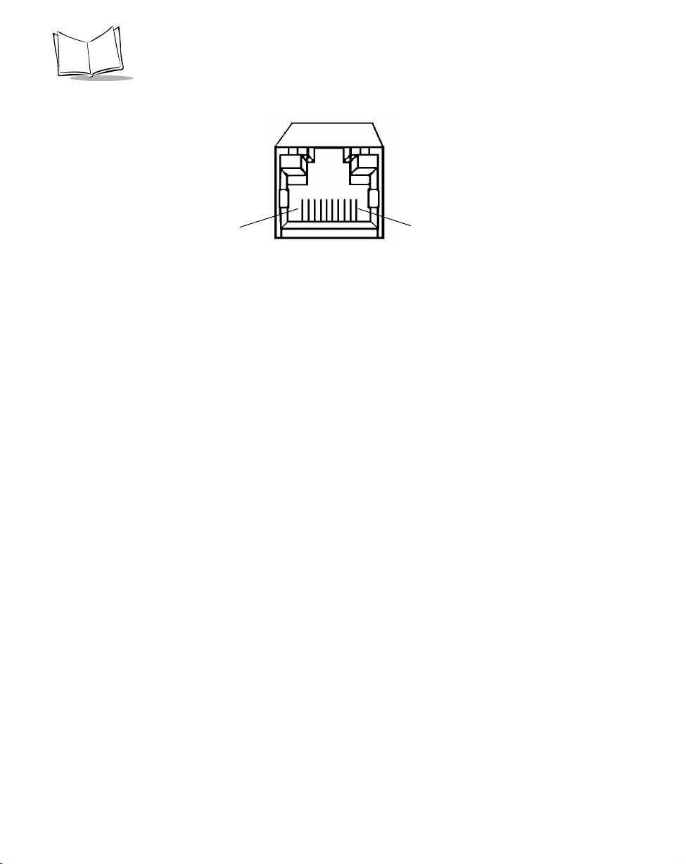
LS 2106 Signal Descriptions
The following signal descriptions apply to the connection between the scanner and the cable,
and are for reference only.
Table 3-1. Signal Descriptions
Pin Signal Name Function
2 VBATT Input power.
3 GROUND Power supply input ground pin and reference for both
output signals. It must be capable of sinking all return
current.
4 Terminal Clock Bidirectional clock signal used to communicate between
the host terminal and the scanner or keyboard.
6 Synapse Data Data line for Synapse communication.
7 Synapse Clock Clock line for Synapse communication.
8 T erminal Data Bidirectional data signal used to communicate between the
host terminal and the scanner or keyboard
9 Keyboard Data Clamp Active-low output data signal used to communicate from
the scanner to the keyboard.
10 Keyboard Clock
Clamp
Active-low output clock signal used to communicate from
the scanner to the keyboard.
3-5
Page 19
LS 2106 Product Reference Guide
Figure 3-1. 10-pin Connector
PIN 1PIN 10
3-6
Page 20

Maintenance and Specifications
Beeper Indications
Standard Use
Beeper Sequence Indication
Short high tone A bar code symbol was decoded (if decode beeper is
enabled).
4 Beeps - long low tone A transmission error has been detected in a scanned
symbol. The data is ignored. This will occur if a unit is
not properly configured. Check option settings.
5 Beeps - low tone Convert or format error
Lo/hi/lo tone ADF transmit error
Hi/hi/hi/lo tone RS-232 receive error
Parameter Menu Scanning
Short high tone Correct entry scanned or correct menu sequence
performed.
Lo/hi tone Input error, incorrect bar code or “Cancel” scanned,
wrong entry , incorrect bar code programming sequence;
remain in program mode.
Hi/lo tone Keyboard parameter selected. Enter value using bar code
keypad.
Hi/lo/hi/lo tone Successful program exit with change in the parameter
setting.
Code 39 Buffering
Hi/lo tone New Code 39 data was entered into the buffer.
3 Beeps - long high tone Code 39 buffer is full.
Lo/hi/lo tone The buffer was erased, or there was an attempt to
transmit an empty buffer. When the Code 39 buffer was
empty, the scanner read a command to clear or to
transmit a Code 39 buffer.
4 Beeps - long low tone Error in data transmission.
Lo/hi tone A successful transmission of buffered data.
3-7
Page 21

Chapter 4
Parameter Menus
Introduction
The LS 2106 is shipped with the settings shown in the Default Parameters beginning on page
4-2. These default values are stored in non-volatile memory and are preserved even when the
scanner is powered down. You can change these default values by scanning the appropriate
bar codes included in this manual. These new values replace the standard default values in
memory . The default parameter values can be recalled by scanning the SET ALL DEF AUL TS
bar code on page 4-7.
The scanner automatically identifies the host type on power-up. It makes this determination
provided the host is powered-up before the scanner is attached to it. The following table lists
the defaults for all parameters. If you wish to change any option, scan the appropriate bar
code(s).
4-1
Page 22

LS 2106 Product Reference Guide
Default Parameters
Table 4-1. Default Parameters
Parameter Default Page
Set Default Parameter All Defaults 4-7
Beeper Volume High 4-8
Laser On Time 3.0 seconds 4-9
Power Mode Continuous 4-10
Beep After Good Decode Enable 4-11
Transmit “No Read” Message Disable 4-12
Decode Redundancy Level 0 4-13
Autodiscriminate Response Time 1 second 4-14
Number
UPC/EAN
UPC-A Enable 4-15
UPC-E Enable 4-15
EAN-8 Enable 4-16
EAN-13 Enable 4-16
Bookland EAN Disable 4-17
Decode UPC/EAN Supplementals Ignore 4-18
Transmit UPC-A Check Digit Enable 4-19
Transmit UPC-E Check Digit Enable 4-19
UPC-A Preamble System Character 4-20
UPC-E Preamble System Character 4-21
4-2
Page 23

Parameter Menus
Table 4-1. Default Parameters (Continued)
Parameter Default Page
Number
Convert UPC-E to A Disable 4-22
EAN-8 Zero Extend Disable 4-23
EAN Zero Extend Code Type EAN13 4-24
Code 128
Code 128 Enable 4-25
UCC/EAN-128 Enable 4-26
Code 39
Code 39 Enable 4-27
Code 39 Check Digit Verification Disable 4-28
Transmit Code 39 Check Digit Disable 4-29
Code 39 Full ASCII Conversion Disable 4-30
Buffer Code 39 Disable 4-31
4-3
Page 24

LS 2106 Product Reference Guide
Table 4-1. Default Parameters (Continued)
Parameter Default Page
Number
Code 93
Code 93 Disable 4-34
Interleaved 2 of 5
Interleaved 2 of 5 Enable 4-35
Set Length(s) for I 2 of 5 14 4-36
Convert I 2 of 5 to EAN 13 Disable 4-37
Discrete 2 of 5
Discrete 2 of 5 Disable 4-38
Set Length(s) for D 2 of 5 12 4-39
Codabar
Codabar Disable 4-40
CLSI Editing Disable 4-41
NOTIS Editing Disable 4-42
4-4
Page 25

Parameter Menus
Table 4-1. Default Parameters (Continued)
Parameter Default Page
Number
MSI Plessey
MSI Plessey Disable 4-43
MSI Plessey Check Digits One 4-44
Transmit MSI Plessey Check Digit Disable 4-45
MSI Plessey Check Digit Algorithm Mod 10/Mod 10 4-46
Data Options
Transmit Code ID Character None 4-48
Prefix/Suffix Values 7013
(<CR/LF> for serial)
Scan Data Transmission Format Data as is 4-51
4-49
4-5
Page 26

LS 2106 Product Reference Guide
Table 4-1. Default Parameters (Continued)
Parameter Default Page
Number
Keyboard Wedge
Host Type IBM PC AT 4-52
National Keyboard Type North American 4-53
Fast Transmit Enabled 4-55
Intercharacter Delay 0 4-56
4-6
Page 27

Parameter Menus
Set Default Parameter
Scanning this bar code returns all parameters to the default values listed in Table 4-1.
beginning on page 4-2.
SET ALL DEFAULTS
4-7
Page 28

LS 2106 Product Reference Guide
Beeper Volume
To select a beeper volume, scan the LOW VOLUME or HIGH VOLUME bar code.
LOW V OLUME
4-8
HIGH VOLUME
Page 29

Parameter Menus
Laser On Time
This parameter sets the maximum time decode processing continues during a scan attempt.
It is programmable in 0.1 second increments from 0.5 to 9.9 seconds.
T o set a Laser On T ime, scan the bar code below . Next scan two numeric bar codes beginning
on page 4-57 that correspond to the desired time on. Single digit numbers must have a leading
zero. For example, to set a Time On of .5 seconds, scan the bar code below, then scan the “0”
and “5” bar codes. If you make an error , or wish to change your selection, scan the CANCEL
bar code on page 4-59.
LASER ON TIME
4-9
Page 30

LS 2106 Product Reference Guide
Power Mode
This parameter determines whether or not power remains on after a decode attempt. When
in low power mode, the scanner enters into a low power consumption mode to preserve
battery life after each decode attempt. When in continuous power mode, power remains on
after each decode attempt.
CONTINUOUS ON
4-10
LOW POWER
Page 31

Parameter Menus
Beep After Good Decode
Scan this symbol if you want the unit to beep after a good decode.
BEEP AFTER GOOD DECODE
Do Not Beep After Good Decode
Scan this symbol if you do not want the unit to beep after a good decode. The beeper still
operates during parameter menu scanning and indicates error conditions.
DO NOT BEEP AFTER GOOD DECODE
4-11
Page 32

LS 2106 Product Reference Guide
Transmit “No Read” Message
When enabled, if a symbol does not decode, “NR” is transmitted. Any prefixes or suffixes
which have been enabled are appended around this message.
ENABLE NO READ
Do Not Transmit “No Read” Message
When disabled, if a symbol does not read, nothing is sent to the host.
4-12
DISABLE NO READ
Page 33

Parameter Menus
Decode Redundancy
Use this parameter to indicate whether the scanner must read a bar code one time (Level 0),
two times (Level 1) or three times (Level 2) before decoding it. A higher level of redundancy
ensures the accuracy of a decode in, for example, poor quality symbols.
LEVEL 0
LEVEL 1
LEVEL 2
4-13
Page 34

LS 2106 Product Reference Guide
Autodiscriminate Response Time
This parameter extends the length of time during which the scanner tries to detect which host
it is connected to on power up.
Note: When connected to an LS 5700/5800, the 5-second option must be
used.
1 SECOND (default)
4-14
5 SECONDS
Page 35

Parameter Menus
Enable/Disable UPC-E/UPC-A
To enable or disable UPC-E or UPC-A, scan the appropriate bar code below.
ENABLE UPC-E
DISABLE UPC-E
ENABLE UPC-A
DISABLE UPC-A
4-15
Page 36

LS 2106 Product Reference Guide
Enable/Disable EAN-8/EAN-13
To enable or disable EAN-8 or EAN-13, scan the appropriate bar code below.
ENABLE EAN-8
DISABLE EAN-8
4-16
ENABLE EAN-13
DISABLE EAN-13
Page 37

Enable/Disable Bookland EAN
To enable or disable EAN Bookland, scan the appropriate bar code below.
ENABLE BOOKLAND EAN
DISABLE BOOKLAND EAN
Parameter Menus
4-17
Page 38

LS 2106 Product Reference Guide
Decode UPC/EAN Supplementals
Supplementals are additionally appended characters (2 or 5) according to specific code
format conventions (e.g., UPC A+2, UPC E+2, EAN 8+2). Three options are available.
If UPC/EAN with supplemental characters is selected, UPC/EAN symbols without
supplemental characters are not decoded.
If UPC/EAN without supplemental characters is selected, and the LS 2106 is presented
with a UPC/EAN plus supplemental symbol, the UPC/EAN is decoded and the
supplemental characters ignored.
An autodiscriminate option is also available. If this option is selected, choose an appropriate
Transmit UPC-A/UPC-E Check Digit value from the next page. A value of 5 or more is
recommended.
Note: In order to minimize the risk of invalid data transmission, it is recommended
that you select whether to read or ignore supplemental characters.
4-18
DECODE UPC/EAN WITH SUPPLEMENTALS
IGNORE UPC/EAN WITH SUPPLEMENTALS
AUTODISCRIMINATE UPC/EAN SUPPLEMENTALS
Page 39

Parameter Menus
Transmit UPC-A/UPC-E Check Digit
Scan the appropriate bar code below to transmit the symbol with or without the UPC-A or
UPC-E check digit.
TRANSMIT UPC-A CHECK DIGIT
DO NOT TRANSMIT UPC-A CHECK DIGIT
TRANSMIT UPC-E CHECK DIGIT
DO NOT TRANSMIT UPC-E CHECK DIGIT
4-19
Page 40

LS 2106 Product Reference Guide
UPC-A Preamble
Three options are given for lead-in characters for UPC-A symbols transmitted to the host
device: transmit system character only, transmit system character and country code (“0” for
USA), and no preamble transmitted. The lead-in characters are considered part of the symbol.
NO PREAMBLE
(<DATA>)
4-20
SYSTEM CHARACTER
(<SYSTEM CHARACTER> <DATA>)
SYSTEM CHARACTER & COUNTRY CODE
(< COUNTRY CODE> <SYSTEM CHARACTER> <DATA>)
Page 41

Parameter Menus
UPC-E Preamble
Three options are given for lead-in characters for UPC-E symbols transmitted to the host
device: transmit system character only, transmit system character and country code (“0” for
USA), and no preamble transmitted. The lead-in characters are considered part of the symbol.
NO PREAMBLE
(<DATA>)
SYSTEM CHARACTER
(<SYSTEM CHARACTER> <DATA>)
SYSTEM CHARACTER & COUNTRY CODE
(< COUNTRY CODE> <SYSTEM CHARACTER> <DATA>)
4-21
Page 42

LS 2106 Product Reference Guide
Convert UPC-E to UPC-A
This parameter converts UPC-E (zero suppressed) decoded data to UPC-A format before
transmission. After conversion, data follows UPC-A format and be affected by UPC-A
programming selections (e.g., Preamble, Check Digit).
Scanning DO NOT CONVERT UPC-E TO UPC-A allows you to transmit
UPC-E (zero suppressed) decoded data.
CONVERT UPC-E TO UPC-A
(ENABLE)
4-22
DO NOT CONVERT UPC-E TO UPC-A
(DISABLE)
Page 43

Parameter Menus
EAN Zero Extend
If this parameter is enabled, five leading zeros are added to decoded EAN-8 symbols to make
them compatible in format to EAN-13 symbols.
Disabling this parameter returns EAN-8 symbols to their normal format.
ENABLE EAN ZERO EXTEND
DISABLE EAN ZERO EXTEND
4-23
Page 44

LS 2106 Product Reference Guide
EAN Zero Extend Code Type
This parameter allows a decoded EAN-8 symbol that has been converted to EAN-13 to be
transmitted with either an EAN-13 code type or an EAN-8 code type.
TYPE IS EAN-13 (Default)
TYPE IS EAN-8
4-24
Page 45

Enable/Disable Code 128
To enable or disable Code 128, scan the appropriate bar code below.
ENABLE CODE 128
Parameter Menus
DISABLE CODE 128
4-25
Page 46

LS 2106 Product Reference Guide
Enable/Disable UCC/EAN-128
To enable or disable UCC/EAN-128, scan the appropriate bar code below.
ENABLE UCC/EAN-128
4-26
DISABLE UCC/EAN-128
Page 47

Enable/Disable Code 39
To enable or disable Code 39, scan the appropriate bar code below.
ENABLE CODE 39
Parameter Menus
DISABLE CODE 39
4-27
Page 48

LS 2106 Product Reference Guide
Code 39 Check Digit Verification
When enabled, this parameter checks the integrity of a Code 39 symbol to ensure it complies
with specified algorithms.
Only those code 39 symbols which include a modulo 43 check digit are decoded when this
parameter is enabled.
ENABLE CODE 39 CHECK DIGIT
4-28
DISABLE CODE 39 CHECK DIGIT
Page 49

Transmit Code 39 Check Digit
Scan this symbol if you want to transmit the check digit with the data.
TRANSMIT CODE 39 CHECK DIGIT
(ENABLE)
Do Not Transmit Code 39 Check Digit
Scan this symbol if you want to transmit the data without the check digit.
Parameter Menus
DO NOT TRANSMIT CODE 39 CHECK DIGIT
(DISABLE)
4-29
Page 50

LS 2106 Product Reference Guide
Enable/Disable Code 39 Full ASCII
To enable or disable Code 39 Full ASCII, scan the appropriate bar code below.
When enabled, the ASCII character set assigns a code to letters, punctuation marks,
numerals, and most control keystrokes on the keyboard.
The first 32 codes are non-printable and are assigned to keyboard control characters such as
BACKSPACE and RETURN. The other 96 are called printable codes because all but SPACE
and DELETE produce visible characters.
Code 39 Full ASCII interprets the bar code special character ($ + % /) preceding a Code 39
character and assigns an ASCII character value to the pair. For example, when Code 39 Full
ASCII is enabled and a +B is scanned, it is interpreted as b, %J as ?, and $H emulates the
keystroke BACKSPACE. Scanning ABC$M outputs the keystroke equivalent of ABC
ENTER.
The scanner does not autodiscriminate between Code 39 and Code 39 Full ASCII.
4-30
ENABLE CODE 39 FULL ASCII
DISABLE CODE 39 FULL ASCII
Page 51

Parameter Menus
Code 39 Buffering (Scan & Store)
When you select the scan and store option, all Code 39 symbols having a leading space as a
first character are temporarily buffered in the unit to be transmitted later. The leading space
is not buffered.
Decode of a valid Code 39 symbol with no leading space causes transmission in sequence of
all buffered data in a first-in first-out format, plus transmission of the “triggering” symbol.
See the following pages for further details.
When the scan and transmit option is selected, decoded Code 39 symbols without leading
spaces are transmitted without being stored in the buffer.
Scan and Store affects Code 39 decodes only . If you select scan and store, we recommend that
you configure the scanner to decode Code 39 symbology only.
BUFFER CODE 39
(ENABLE)
DO NOT BUFFER CODE 39
(DISABLE)
While there is data in the transmission buffer, deleting Code 39 buffering capability via
the parameter menu is not allowed. The buffer holds 200 bytes of information.
To allow disabling of Code 39 buffering, first force the buffer transmission (see Transmit
Buffer) or clear the buffer . Both the CLEAR BUFFER and TRANSMIT BUFFER bar codes
are length 1. Be sure Code 39 length is set to include length 1.
4-31
Page 52

LS 2106 Product Reference Guide
Buffer Data
To buffer data, Code 39 buffering must be enabled, and a symbol must be read with a space
immediately following the start pattern.
t Unless symbol overflows the transmission buffer, the unit gives a lo/hi beep to
indicate successful decode and buffering. See Overfilling Transmission Buffer.
t Unit adds the message, excluding the leading space to the transmission buffer.
t No transmission occurs.
Clear Transmission Buffer
To clear the transmission buffer, read a symbol which contains only a start character, a dash
(minus), and a stop character.
t Unit issues a short hi/lo/hi beep to signal that the transmission buffer has been erased,
and no transmission has occurred.
t Unit erases the transmission buffer.
t No transmission occurs.
4-32
CLEAR BUFFER
Page 53

Parameter Menus
Transmit Buffer
To transmit the buffer, read a symbol containing either the first or second condition:
1. Only a start character, a plus (+), and a stop character.
s The unit signals that the transmission buffer has been sent (a lo/hi beep).
s Unit sends the buffer.
s Unit clears the buffer.
TRANSMIT BUFFER
2. A Code 39 bar code with leading character other than a space.
s The unit signals a good decode and buffering of that decode has occurred by
giving a hi/lo beep.
s Unit transmits the buffer.
s Unit signals that the buffer has been transmitted with a lo/hi beep.
Overfilling T ransmission Buffer
If the symbol just read results in an overflow of the transmission buffer:
t Unit indicates that the symbol has been rejected by issuing three long, high beeps.
s No transmission occurs. Data in buffer is not affected.
Attempt to Transmit an Empty Buffer
If the symbol just read was the transmit buffer symbol and the Code 39 buffer is empty:
t A short lo/hi/lo beep signals that the buffer is empty.
t No transmission occurs.
t The buffer remains empty.
4-33
Page 54

LS 2106 Product Reference Guide
Enable/Disable Code 93
To enable or disable Code 93, scan the appropriate bar code below.
ENABLE CODE 93
4-34
DISABLE CODE 93
Page 55

Parameter Menus
Enable/Disable Interleaved 2 of 5
To enable or disable Interleaved 2 of 5, scan the appropriate bar code below.
ENABLE INTERLEAVED 2 OF 5
DISABLE INTERLEAVED 2 OF 5
4-35
Page 56

LS 2106 Product Reference Guide
Set Lengths for Interleaved 2 of 5
Lengths for I 2 of 5 may be set for any length, one or two discrete lengths, or lengths within
a specific range. The length of a code refers to the number of characters (i.e., human readable
characters) the code contains, and includes check digits.
One Discrete Length - This option allows you to decode only those codes containing a
selected length. For example, if you select I 2 of 5 One Discrete Length, then scan 1, 4, the
only I 2 of 5 symbols decoded are those containing 14 characters. Numeric bar codes begin
on page 4-57. If you make an error or wish to change your selection, scan CANCEL on
page 4-59.
I 2 of 5 - ONE DISCRETE LENGTH
Two Discrete Lengths - This option allows you to decode only those codes containing two
selected lengths. For example, if you select I 2 of 5 Two Discrete Lengths, then scan 0, 2, 1,
4, the only I 2 of 5 symbols decoded are those containing 2 or 14 characters. Numeric bar
codes begin on page 4-57. If you make an error or wish to change your selection, scan
CANCEL on page 4-59.
4-36
I 2 of 5 - TWO DISCRETE LENGTHS
Page 57

Parameter Menus
Convert I 2 of 5 to EAN-13
This parameter converts a 14 character I 2 of 5 code into EAN-13, and transmits to the host
as EAN-13. In order to accomplish this, the I 2 of 5 code must be enabled, one length must
be set to 14, and the code must have a leading zero and a valid EAN-13 check digit.
CONVERT I 2 of 5 to EAN-13
(ENABLE)
DO NOT CONVERT I 2 of 5 to EAN-13
(DISABLE)
4-37
Page 58

LS 2106 Product Reference Guide
Enable/Disable Discrete 2 of 5
To enable or disable Discrete 2 of 5, scan the appropriate bar code below.
ENABLE DISCRETE 2 OF 5
4-38
DISABLE DISCRETE 2 OF 5
Page 59

Parameter Menus
Set Lengths for Discrete 2 of 5
Lengths for D 2 of 5 may be set for any length, one or two discrete lengths, or lengths within
a specific range. The length of a code refers to the number of characters (i.e., human readable
characters) the code contains, and includes check digits.
One Discrete Length - This option allows you to decode only those codes containing a
selected length. For example, if you select D 2 of 5 One Discrete Length, then scan 1, 4, the
only D 2 of 5 symbols decoded are those containing 14 characters. Numeric bar codes begin
on page 4-57. If you make an error or wish to change your selection, scan CANCEL on
page 4-59.
D 2 of 5 - ONE DISCRETE LENGTH
Two Discrete Lengths - This option allows you to decode only those codes containing two
selected lengths. For example, if you select D 2 of 5 Two Discrete Lengths, then scan 0, 2, 1,
4, the only D 2 of 5 symbols decoded are those containing 2 or 14 characters. Numeric bar
codes begin on page 4-57. If you make an error or wish to change your selection, scan
CANCEL on page 4-59.
D 2 of 5 - TWO DISCRETE LENGTHS
4-39
Page 60

LS 2106 Product Reference Guide
Enable/Disable Codabar
To enable or disable Codabar, scan the appropriate bar code below.
ENABLE CODABAR
4-40
DISABLE CODABAR
Page 61

Parameter Menus
CLSI Editing
When enabled, this parameter strips the start and stop characters and inserts a space after the
first, fifth, and tenth characters of a 14-character Codabar symbol.
Note: Symbol length does not include start and stop characters.
ENABLE CLSI EDITING
DISABLE CLSI EDITING
4-41
Page 62

LS 2106 Product Reference Guide
NOTIS Editing
When enabled, this parameter strips the start and stop characters from decoded Codabar
symbol.
ENABLE NOTIS EDITING
4-42
DISABLE NOTIS EDITING
Page 63

Parameter Menus
Enable/Disable MSI Plessey
To enable or disable MSI Plessey, scan the appropriate bar code below.
ENABLE MSI PLESSEY
DISABLE MSI PLESSEY
4-43
Page 64

LS 2106 Product Reference Guide
MSI Plessey Check Digits
These check digits, at the end of the bar code verify the integrity of the data. At least one
check digit is always required. Check digits are not automatically transmitted with the data.
ONE MSI Plessey CHECK DIGIT
4-44
TWO MSI Plessey CHECK DIGIT
Page 65

Transmit MSI Plessey Check Digit
Scan this symbol if you want to transmit the check digit with the data.
TRANSMIT MSI Plessey CHECK DIGIT
(ENABLE)
Do Not Transmit MSI Plessey Check Digit
Scan this symbol if you want to transmit the data without the check digit.
Parameter Menus
DO NOT TRANSMIT MSI Plessey CHECK DIGIT
(DISABLE)
4-45
Page 66

LS 2106 Product Reference Guide
MSI Plessey Check Digit Algorithm
When the two MSI Plessey check digits option is selected, an additional verification is
required to ensure integrity. Either of the two following algorithms may be selected.
MOD 11/MOD 10
4-46
MOD 10/MOD 10
Page 67

Parameter Menus
Transmit Code ID Character
A code ID character identifies the code type of a scanned bar code. This may be useful when
the scanner is decoding more than one code type. In addition to any single character prefix
already selected, the code ID character is inserted between the prefix and the decoded symbol.
The user may select no code ID character, a Symbol Code ID character, or an AIM Code ID
character. The Symbol Code ID characters are listed below.
A = UPC-A, UPC-E, EAN-8, EAN-13
B = Code 39
C = Codabar
D = Code 128
E = Code 93
F = Interleaved 2 of 5
G = Discrete 2 of 5, or Discrete 2 of 5 IATA
J = MSI Plessey
K = UCC/EAN-128
L = Bookland EAN
4-47
Page 68

LS 2106 Product Reference Guide
Transmit Code ID Character
SYMBOL CODE ID CHARACTER
AIM CODE ID CHARACTER
4-48
NONE
Page 69

Parameter Menus
Prefix/Suffix Values
A prefix/suffix may be appended to scan data for use in data editing. These values are set by
scanning a four-digit number (i.e. four bar codes) that corresponds to key codes for various
terminals. See T able A-1 on page A-1 for conversion information. Numeric bar codes begin
on page 4-57. If you make an error or wish to change your selection, scan CANCEL on
page 4-59.
SCAN PREFIX
SCAN SUFFIX
SCAN SUFFIX 2
4-49
Page 70

LS 2106 Product Reference Guide
Scan Data Transmission Format
Use this parameter to change the format of the scanned data.
DATA AS IS
<DATA><SUFFIX 1>
4-50
<DATA> <SUFFIX 2>
Page 71

Scan Data Transmission Format (cont’d)
<DATA <SUFFIX 1><SUFFIX 2>
<PREFIX> <DATA>
Parameter Menus
<PREFIX><DATA><SUFFIX 1>
<PREFIX><DATA><SUFFIX 2>
<PREFIX><DATA><SUFFIX 1><SUFFIX 2>
4-51
Page 72

LS 2106 Product Reference Guide
Host Interfaces
Use these bar codes to select your host interface.
IBM PC/AT IBM PS/2-50, 55SX, 60, 70, 80 (Default)
IBM PS/2-30
4-52
IBM PC/XT
NCR 7052
Page 73

National Keyboard Types
Use these bar codes to select the appropriate national keyboard type.
North American (Default)
French
Parameter Menus
German
French International
4-53
Page 74

LS 2106 Product Reference Guide
Spanish
Italian
4-54
Swedish
British
Page 75

Parameter Menus
Fast T ransmit
Older systems may require a slower transmission method. If your system still needs additional
time to process keyboard dat after setting an Intercharacter Delay, scan the DISABLE FAST
TRANSMIT bar code.
ENABLE FAST TRANSMIT
DISABLE FAST TRANSMIT (Default)
4-55
Page 76

LS 2106 Product Reference Guide
Intercharacter Delay
Select the intercharacter delay option matching host requirements. The intercharacter delay
gives the host system time to service its receiver and perform other tasks between characters.
The delay period can range from no delay to 99 msec in 1-msec increments. After scanning
the bar code below, scan two bar codes beginning on page 4-57 to set the desired time-out.
If you make an error or wish to change your selection, scan CANCEL on page 4-59.
INTERCHARACTER DELAY
4-56
Page 77

Parameter Menus
Numeric Bar Codes
For parameters requiring specific numeric values, scan the appropriately numbered bar
code(s).
0
1
2
3
4-57
Page 78

LS 2106 Product Reference Guide
Numeric Bar Codes (cont’d)
4
5
4-58
6
7
8
Page 79

Parameter Menus
Numeric Bar Codes (cont’d)
9
Cancel
If you make an error or wish to change your selection, scan the bar code below.
CANCEL
4-59
Page 80

LS 2106 Product Reference Guide
Keyboard Maps
The keyboard maps on the following pages are provided for prefix/suffix keystroke
parameters, and are used only with scanners that support data formatting. To program the
prefix/suffix values, see the bar codes on page 4-49.
5001
5003
5005
5007
5009
5001
5003
5005
5007
5009
5002
5004
5006
5008
5010
5002
5004
5006
5008
5010
7009
7014
7009
Figure 4-1. IBM PC/XT Keyboard
Figure 4-2. IBM PC/AT Keyboard
7008
7013
7008
7013
7012
7004
7011 7002
7014
7012
7004
7011
7003
7006
7003
7002
4-60
Page 81

Normal
CNTRL
Parameter Menus
7014
5001 5002 5003 5004 5005 5006 5007 5008
7019
7009
5009 5010 5011 5012
7008
7013
7013
Figure 4-3. IBM PS2 Keyboard
5002
5001
5003
5004
5005 5006
5007
5008
5009
5010
5011
5012
1048
(1048 if double key)
1046
7010
3023
7011
7002
7017
1045
5013
5014
5015
1043
5016
5018
5017
7013
5019
(7013 if double key)
7006
7001
7012 7003
7004
7005
7015
7016
7018
6047
6042
6045
6043
6058
Figure 4-4. NCR 7052 32-Key Keyboard
4-61
Page 82

LS 2106 Product Reference Guide
5012
1068
1075
1082
1046
1070
1069
1076
1077
1083 1084
1045
5013
5014
5015
1043
5016
5018
5017
7013
5019
(1043 if double key)
1066
1065
1072
1073
1079 1080
5002
5001
5003
5004
5005 5006
5007
5008
5009
5010
1067
1074
1081
5011
1048
(1048 if double key)
Figure 4-5. NCR 7052 58-Key Keyboard
1071
1078
1085
1086
1087
1088
1089
1090
4-62
Page 83

Appendix A
ASCII Character Set
Table A-1. ASCII Character Set
ASCII Value Full ASCII
Code 39
Encode Char.
1000 %U CTRL 2
1001 $A CTRL A
1002 $B CTRL B
1003 $C CTRL C
1004 $D CTRL D
1005 $E CTRL E
1006 $F CTRL F
1007 $G CTRL G
1008 $H CTRL H
1009 $I CTRL I
1010 $J CTRL J
1011 $K CTRL K
1012 $L CTRL L
1013 $M CTRL M
Keystroke
A-1
Page 84

LS 2106 Product Reference Guide
Table A-1. ASCII Character Set (Continued)
1014 $N CTRL N
1015 $O CTRL O
1016 $P CTRL P
1017 $Q CTRL Q
1018 $R CTRL R
1019 $S CTRL S
1020 $T CTRL T
1021 $U CTRL U
1022 $V CTRL V
1023 $W CTRL W
1024 $X CTRL X
1025 $Y CTRL Y
1026 $Z CTRL Z
1027 %A CTRL [
A-2
1028 %B CTRL \
1029 %C CTRL ]
1030 %D CTRL 6
1031 %E CTRL 1032 Space Space
1033 /A !
1034 /B ‘
1035 /C #
1036 /D E
1037 /E %
1038 /F &
1039 /G ‘
1040 /H (
Page 85

Table A-1. ASCII Character Set (Continued)
1041 /I )
1042 /J *
1043 /K +
1044 /L ,
1045 - 1046 . .
1047 / /
1048 0 0
1047 1 1
1050 2 2
1051 3 3
1052 4 4
1053 5 5
1054 6 6
ASCII Character Set
1055 7 7
1056 8 8
1057 9 9
1058 /Z :
1059 %F ;
1060 %G <
1061 %H =
1062 %I >
1063 %J ?
1064 %V @
1065 A A
1066 B B
1067 C C
A-3
Page 86

LS 2106 Product Reference Guide
Table A-1. ASCII Character Set (Continued)
1068 D D
1069 E E
1070 F F
1071 G G
1072 H H
1073 I I
1074 J J
1075 K K
1076 L L
1077 M M
1078 N N
1079 O O
1080 P P
1081 Q Q
A-4
1082 R R
1083 S S
1084 T T
1085 U U
1086 V V
1087 W W
1088 X X
1089 Y Y
1090 Z Z
1091 %K [
1092 %L \
1093 %M ]
1094 %N ^
Page 87

Table A-1. ASCII Character Set (Continued)
1095 %O _
1096 %W ‘
1097 +A a
1098 +B b
1099 +C c
1100 +D d
1101 +E e
1102 +F f
1103 +G g
1104 +H h
1105 +I i
1106 +J j
1107 +K k
1108 +L l
ASCII Character Set
1109 +M m
1110 +N n
1111 +O o
1112 +P p
1113 +Q q
1114 +R r
1115 +S s
1116 +T t
1117 +U u
1118 +V v
1119 +W w
1120 +X x
1121 +Y y
A-5
Page 88

LS 2106 Product Reference Guide
Table A-1. ASCII Character Set (Continued)
1122 +Z z
1123 %P {
1124 %Q |
1125 %R }
1126 %S ~
1127 Undefined
1128
ALT Keys Keystroke
2064 ALT 2
2065 ALT A
2066 ALT B
2067 ALT C
2068 ALT D
2069 ALT E
A-6
2070 ALT F
2071 ALT G
2072 ALT H
2073 ALT I
2074 ALT J
2075 ALT K
2076 ALT L
2077 ALT M
2078 ALT N
2079 ALT O
2080 ALT P
2081 ALT Q
2082 ALT R
Page 89

Table A-1. ASCII Character Set (Continued)
2083 ALT S
2084 ALT T
2085 ALT U
2086 ALT V
2087 ALT W
2088 ALT X
2089 ALT Y
2090 ALT Z
2091 ALT [
2092 ALT \
2093 ALT ]
2094 ALT 6
2095 ALT -
Misc. Key Keystroke
ASCII Character Set
3001 PA 1
3002 PA 2
3003 CMD 1
3004 CMD 2
3005 CMD 3
3006 CMD 4
3007 CMD 5
3008 CMD 6
3009 CMD 7
3010 CMD 8
3011 CMD 9
3012 CMD 10
3013 ¥
A-7
Page 90

LS 2106 Product Reference Guide
Table A-1. ASCII Character Set (Continued)
3014 £
3015 ¤
3016 ¬
3017 °
3018 1/2
3019 ¶
3020 §
3021 |
3022 0/00
PF Keys Keystrokes
4001 PF 1
4002 PF 2
4003 PF 3
4004 PF 4
A-8
4005 PF 5
4006 PF 6
4007 PF 7
4008 PF 8
4009 PF 9
4010 PF 10
4011 PF 11
4012 PF 12
4013 PF 13
4014 PF 14
4015 PF 15
4016 PF 16
4017 PF 17
Page 91

Table A-1. ASCII Character Set (Continued)
4018 PF 18
4019 PF 19
4020 PF 20
4021 PF 21
4022 PF 22
4023 PF 23
4024 PF 24
F Keys Keystroke
5001 F1
5002 F2
5003 F3
5004 F4
5005 F5
5006 F6
ASCII Character Set
5007 F7
5008 F8
5009 F9
5010 F10
5011 F11
5012 F12
5013 F13
5014 F14
5015 F15
5016 F16
5017 F17
5018 F18
5019 F19
A-9
Page 92

LS 2106 Product Reference Guide
Table A-1. ASCII Character Set (Continued)
5020 F20
5021 F21
5022 F22
5023 F23
5024 F24
5025 F25
5026 F26
5027 F27
5028 F28
5029 F29
5030 F30
5031 F31
5032 F32
5033 F33
A-10
5034 F34
5035 F35
5036 F36
5037 F37
5038 F38
5039 F39
5040 F40
Numeric
Keypad
6042 *
6043 +
6044 undefined
6045 -
Keystroke
Page 93

Table A-1. ASCII Character Set (Continued)
6046 .
6047 /
6048 0
6049 1
6050 2
6051 3
6052 4
6053 5
6054 6
6055 7
6056 8
6057 9
6058 Enter
6059 Num Lock
ASCII Character Set
6060 00
Extended
Keypad
7001 Break
7002 Delete
7003 Pg Up
7004 End
7005 Pg Dn
7006 Pause
7007 Scroll Lock
7008 Backspace
7009 Tab
7010 Print Screen
7011 Insert
Keystroke
A-11
Page 94

LS 2106 Product Reference Guide
Table A-1. ASCII Character Set (Continued)
7012 Home
7013 Enter
7014 Escape
7015 Up Arrow
7016 Dn Arrow
7017 Left Arrow
7018 Right Arrow
7019 Back Tab
A-12
Page 95

Glossary
Aperture The opening in an optical system defined by a lens or baffle that
establishes the field of view.
ASCII American Standard Code for Information Interchange. A 7 bit-plus-
parity code representing 128 letters, numerals, punctuation marks,
and control characters. It is a standard data transmission code in the
U.S.
Autodiscrimination The ability of an interface controller to determine the code type of a
scanned bar code. After this determination is made, the information
content can be decoded.
Bar The dark element in a printed bar code symbol.
Bar Code Density The number of characters represented per unit of measurement
(e.g., characters per inch).
Bar Height The dimension of a bar measured perpendicular to the bar width.
Bar Width Thickness of a bar measured from the edge closest to the symbol start
character to the trailing edge of the same bar.
Baud Rate A measure of the data flow or number of signaling events occurring
per second. When one bit is the standard "event," this is a measure of
bits per second (bps). For example, a baud rate of 50 means
transmission of 50 bits of data per second.
Bit Binary digit. One bit is the basic unit of binary information. Generally,
eight consecutive bits compose one byte of data. The pattern of 0 and
1 values within the byte determines its meaning.
Glossary-1
Page 96

LS 2106 Product Reference Guide
Byte On an addressable boundary, eight adjacent binary digits (0 and 1)
combined in a pattern to represent a specific character or numeric
value. Bits are numbered from the right, 0 through 7, with bit 0 the
low-order bit. One byte in memory can be used to store one ASCII
character.
CDRH Center for Devices and Radiological Health. A federal agency
responsible for regulating laser product safety. This agency specifies
various laser operation classes based on power output during
operation.
CDRH Class 1 This is the lowest power CDRH laser classification. This class is
considered intrinsically safe, even if all laser output were directed
into the eye's pupil. There are no special operating procedures for this
class.
CDRH Class 2 No additional software mechanisms are needed to conform to this
limit. Laser operation in this class poses no danger for unintentional
direct human exposure.
Character A pattern of bars and spaces which either directly represents data or
indicates a control function, such as a number, letter, punctuation
mark, or communications control contained in a message.
Character Set Those characters available for encodation in a particular bar code
symbology.
Check Digit A digit used to verify a corr ect symbol decode. The scanner inserts the
decoded data into an arithmetic formula and checks that the resulting
number matches the encoded check digit. Check digits are required
for UPC but are optional for other symbologies. Using check digits
decreases the chance of substitution errors when a symbol is decoded.
Codabar A discrete self-checking code with a character set consisting of digits
0 to 9 and six additional characters: ( - $ : / , +).
Code 128 A high density symbology which allows the controller to encode all
128 ASCII characters without adding extra symbol elements.
Code 3 of 9 (Code 39) A versatile and widely used alphanumeric bar code symbology with
a set of 43 character types, including all uppercase letters, numerals
from 0 to 9, and 7 special characters (- . / + % $ and space). The code
name is derived from the fact that 3 of 9 elements representing a
character are wide, while the remaining 6 are narrow.
Code 93 An industrial symbology compatible with Code 39 but offering a full
character ASCII set and a higher coding density than Code 39.
Glossary-2
Page 97

Glossary
Code Length Number of data characters in a bar code between the start and stop
characters, not including those characters.
Continuous Code A bar code or symbol in which all spaces within the symbol are parts
of characters. There are no intercharacter gaps in a continuous code.
The absence of gaps allows for greater information density.
Dead Zone An area within a scanner's field of view, in which specular reflection
may prevent a successful decode.
Decode To recognize a bar code symbology (e.g., UPC/EAN) and then
analyze the content of the specific bar code scanned.
Decode Algorithm A decoding scheme that converts pulse widths into data
representation of the letters or numbers encoded within a bar code
symbol.
Depth of Field The range between minimum and maximum distances at which a
scanner can read a symbol with a certain minimum element width.
Discrete Code A bar code or symbol in which the spaces between characters
(intercharacter gaps) are not part of the code.
Discrete 2 of 5 A binary bar code symbology representing each character by a group
of five bars, two of which are wide. The location of wide bars in the
group determines which character is encoded; spaces are
insignificant. Only numeric characters (0 to 9) and START/STOP
characters may be encoded.
EAN European Article Number. This European/International version of
the UPC provides its own coding format and symbology standards.
Element dimensions are specified metrically. EAN is used primarily
in retail.
Element Generic term for a bar or space.
Encoded Area Total linear dimension occupied by all characters of a code pattern,
including start/stop characters and data.
Host Computer A computer that serves other terminals in a network, providing such
services as computation, database access, supervisory programs, and
network control.
IEC International Electrotechnical Commission. This international agency
regulates laser safety by specifying various laser operation classes
based on power output during operation.
Glossary-3
Page 98

LS 2106 Product Reference Guide
IEC (825) Class 1 This is the lowest power IEC laser classification. Conformity is
ensured through a software restriction of 120 seconds of laser
operation within any 1000 second window and an automatic laser
shutdown if the scanner's oscillating mirror fails.
Intercharacter Gap The space between two adjacent bar code characters in a discrete
code.
Interleaved Bar Code A bar code in which characters are paired together, using bars to
represent the first character and the intervening spaces to represent
the second.
Interleaved 2 of 5 A binary bar code symbology representing character pairs in groups
of five bars and five interleaved spaces. Interleaving provides for
greater information density. The location of wide elements (bar/
spaces) within each group determines which characters are encoded.
This continuous code type uses no intercharacter spaces. Only
numeric (0 to 9) and START/STOP characters may be encoded.
LASER - Light
Amplification by
Stimulated Emission
of Radiation
Laser Diode A gallium-arsenide semiconductor type of laser connected to a power
The laser is an intense light source. Light from a laser is all the same
frequency, unlike the output of an incandescent bulb. Laser light is
typically coherent and has a high energy density.
source to generate a laser beam. This laser type is a compact source of
coherent light.
LED Indicator A semiconductor diode (LED - Light Emitting Diode) used as an
indicator, often in digital displays. The semiconductor uses applied
voltage to produce light of a certain frequency determined by the
semiconductor's particular chemical composition.
MIL 1 mil = 1 thousandth of an inch.
Misread
(Misdecode)
Nominal The exact (or ideal) intended value for a specified parameter.
Nominal Size Standard size for a bar code symbol. Most UPC/EAN codes can be
Parameter A variable that can have different values assigned to it.
A condition which occurs when the data output of a reader or
interface controller does not agree with the data encoded within a bar
code symbol.
T olerances are specified as positive and negative deviations fr om this
value.
used over a range of magnifications (e.g., from 0.80 to 2.00 of
nominal).
Glossary-4
Page 99

Glossary
Percent Decode The average probability that a single scan of a bar code would result
in a successful decode. In a well-designed bar code scanning system,
that probability should approach near 100%.
Print Contrast Signal
(PCS)
Programming Mode The state in which a scanner is configured for parameter values. See
Quiet Zone A clear space, containing no dark marks, which precedes the start
Reflectance Amount of light returned from an illuminated surface.
Resolution The narrowest element dimension which can be distinguished by a
Scan Area Area intended to contain a symbol.
Scanner An electronic device used to scan bar code symbols and produce a
Scanning Mode The scanner is energized, programmed, and ready to read a bar code.
Measurement of the contrast (brightness difference) between the bars
and spaces of a symbol. A minimum PCS value is needed for a bar
code symbol to be scannable. PCS = (RL - RD) / RL, where RL is the
reflectance factor of the background and RD the reflectance factor of
the dark bars.
SCANNING MODE.
character of a bar code symbol and follows the stop character.
particular reading device or printed with a particular device or
method.
digitized pattern that corresponds to the bars and spaces of the
symbol. Its three main components are:
1. Light source (laser or photoelectric cell) - illuminates a bar code.
2. Photodetector - registers the difference in reflected light (mor e light
reflected from spaces).
3. Signal conditioning circuit - transforms optical detector output into
a digitized bar pattern.
Scanning Sequence A method of programming or configuring parameters for a bar code
reading system by scanning bar code menus.
Self-Checking Code A symbology that uses a checking algorithm to detect encoding err ors
within the characters of a bar code symbol.
Space The lighter element of a bar code formed by the background between
bars.
Specular Reflection The mirror-like reflection of light from a surface, which can “blind” a
scanner.
Glossary-5
Page 100

LS 2106 Product Reference Guide
Start/Stop Character A pattern of bars and spaces that pr ovides the scanner with start and
stop reading instructions and scanning direction. The start and stop
characters are normally to the left and right margins of a horizontal
code.
Substrate A foundation material on which a substance or image is placed.
Symbol A scannable unit that encodes data within the conventions of a certain
symbology , usually including start/stop characters, quiet zones, data
characters, and check characters.
Symbol Aspect Ratio The ratio of symbol height to symbol width.
Symbol Height The distance between the outside edges of the quiet zones of the first
row and the last row.
Symbol Length Length of symbol measured from the beginning of the quiet zone
(margin) adjacent to the start character to the end of the quiet zone
(margin) adjacent to a stop character.
Symbology The structural rules and conventions for representing data within a
particular bar code type (e.g. UPC/EAN, Code 39).
Tolerance Allowable deviation from the nominal bar or space width.
UPC Universal Product Code. A relatively complex numeric symbology.
Each character consists of two bars and two spaces, each of which can
be any of four widths. The standard symbology for retail food
packages in the United States.
Visible Laser Diode
(VLD)
Glossary-6
A solid state device which produces visible laser light. Laser light
emitted from the diode has a wavelength of 670 to 680 nanometers.
 Loading...