

Page 1
LS 1000
Product Reference Guide
Click on red text at any location in the manual to jump to the
specified chapter, topic, or reference.
Table of Contents
Copyright
Chapter 1
Chapter 2
Chapter 3
Chapter 4
Chapter 5
Chapter 6
70-17529-01
Revision A
March, 1996
Appendix A
Page 2

Copyright 1996 by Symbol Technologies, Inc. All rights reserved.
No part of this publication may be reproduced or used in any form, or by any electrical or
mechanical means, without permission in writing from Symbol. This includes electronic or
mechanical means, such as photocopying, recording, or information storage and retrieval
systems. The material in this manual is subject to change without notice.
Symbol reserves the right to make changes to any product to improve r eliability, function,
or design.
Symbol does not assume any product liability arising out of, or in connection with, the
application or use of any product, circuit, or application described herein.
No license is granted, either expressly or by implication, estoppel, or otherwise under any
patent right or patent, covering or relating to any combination, system, apparatus,
machine, material, method, or process in which Symbol products might be used. An
implied license only exists for equipment, circuits, and subsystems contained in Symbol
products.
Symbol Technologies, Inc.
One Symbol Plaza
Holtsville, N.Y. 11742-1300
http://www.symbol.com
FCC and Industry Canada Information
This device complies with Part 15 of the FCC rules.. Operation is subject to the following
two conditions: (1) this device may not cause harmful interference, and (2) this device must
accept any interference received, including interference that may cause undesired
operation. This Class A digital apparatus meets all requirements of the Canadian
Interference-Causing Equipment Regulations. Cet appareil numérique de la classe A
respecte toutes les exigences du Règlement sur le matériel brouilleur du Canada.
Page 3

Factory Service
If you have a problem, contact the Symbol Support Center at the telephone
number on the next page.
Before calling, have the model number and several of your bar code symbols
at hand.
Call the Support Center from a phone near the scanning equipment so that the
service person can try to talk you through your problem. If the equipment is
found to be working properly and the problem is symbol readability, Samples
of your bar codes will be requested for analysis at our facility.
If your problem cannot be solved over the phone, you may need to return your
equipment for servicing. If that is necessary, you will be given specific
directions.
Note:
Symbol T echnologies is not r esponsible for any
damages incurred during shipment if the approved
shipping container is not used. Shipping the units
improperly can possibly void the warranty. If the
original shipping container was not kept, contact
Symbol to have another sent to you.
Page 4

Symbol Support Center
In the U.S.A., for service information, warranty information or technical
assistance call:
SYMBOL SUPPORT CENTER
1-800-653-5350
If you purchased your Symbol product from a Symbol Business Partner,
contact that Business Partner for service.
Canada
Mississauga, Ontario
Canadian Headquarters
(905) 629-7226
Europe
Wokingham, England
European Headquarters
01734-771-222 (Inside UK)
+44-1734-771-222 (Outside UK)
Asia
Singapore
Symbol Technologies Asia, Inc.
337-6588 (Inside Singapore)
+65-337-6588 (Outside Singapore)
Page 5

Contents
Factory Service
Symbol Support Center
Chapter 1. Introduction and Set-up
Introduction
Audience
Set-Up3
Unpacking
Installing the Cable
Switching Cables
Connecting to a Host
Chapter 2. Scanning
Introduction
Ready, Test, Scan
Aiming
Chapter 3. Maintenance & Specifications
Introduction
Maintaining the LS 1000 Scanner
Accessories
LS 100x Technical Specifications
LS 100x Decode Zone
Chapter 4. Programming The LS 1004
Introduction
Scanning Sequence
Scanning Sequence Example
Errors While Scanning
Parameter Descriptions
Set Parameter Defaults
Host Interface Select
Power On Beep Enable/Disable
Beeper after Decode
Beeper Tone
Beeper Volume
vii
Page 6

PPT 4600 Product Reference Guide: Contents
Decode Attempt Time
Operating Mode
Aggressive Scan Mode
Transmit “No Decode” Message
Decode Redundancy
Code Types
UPC/EAN
Code 128
Code 39
Code 93
Interleaved 2 of 5
Discrete 2 of 5
Codabar
Data Options
RS-232C
Chapter 5. Glossary
Chapter 6. ASCII Character Set
ASCII Character Set
Appendix A. Errata
viii
Page 7

Chapter 1 Introduction and Set-up
Introduction
Symbol T echnologies Inc., the world leader in hand-held laser scanning now offers 21st
century technology, while maintaining compatibility with today’s existing systems.
The LS 1000 Series of hand-held laser scanners offers the best performance in retail and
light industrial applications. Advanced ergonomic design ensur es comfortable use for
extended periods of time.
The LS 1000 series hand-held scanner is based on the Visible Laser Diode (VLD). This
state of the art technology gives the scanner a wider decode zone, greater depth of
field, and a visible scan beam. This model reads color bar codes and symbols printed
on all substrates. See LS 100x Decode Zone .
Here’s what each member of the LS 1000 family offers you:
• LS 1000 - The aggressiveness of this discrete scanner is typical of the
LS 1000 family’s performance. It connects easily to, and is programmed by, the
complete line of Symbol Technologies portable terminals and the full range of
SYMBOLLINK® and OmniLink
• LS 1004 - With a simple cable change, this scanner is compatible with:
- RS 232C asynchronous terminals
- Synapsetm “Smart Cables”, which allow you to connect to
IBM 4683/4, 4693/4 series of terminals
All leading OCIA terminals, including NCR, Nixdorf, and ICL terminals,
using an XT, AT, or PS/2 -style keyboard (when using as a keyboard wedge,
all scanned data is entered into your terminal in the form of keystrokes - no
changes to your host system are necessary)
- Popular OCR terminals, such as Fujitsu and ICL.
All of the LS 1000 series scan automatically at the rate of 36 scans per second. For
decode capability, see LS 100x Technical Specifications .
tm
interface controllers.
1-1
Page 8

LS 1000 Product Reference Guide: Chapter 1, Introduction and Setup
Audience
The intended audience for this manual is personnel performing installation/setup and
programming of LS 100x scanners.
1-2
Page 9
LS 1000 Product Reference Guide: Chapter 1, Introduction and Setup
Set-Up
Unpacking
Remove the scanner from its packing and inspect it for damage. If the scanner was
damaged in transit, call the
listed in the front of this manual. KEEP THE PACKING. It is the approved shipping
container and should be used if you ever need to return your equipment for servicing.
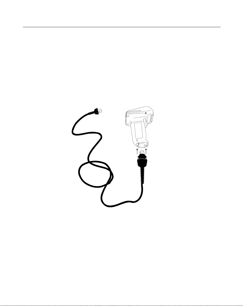
Installing the Cable
1. Insert the cable into the receptable on the bottom of the scanner, as shown below:
Symbol Support Center
at one of the telephone numbers
1-3
Page 10
LS 1000 Product Reference Guide: Chapter 1, Introduction and Setup
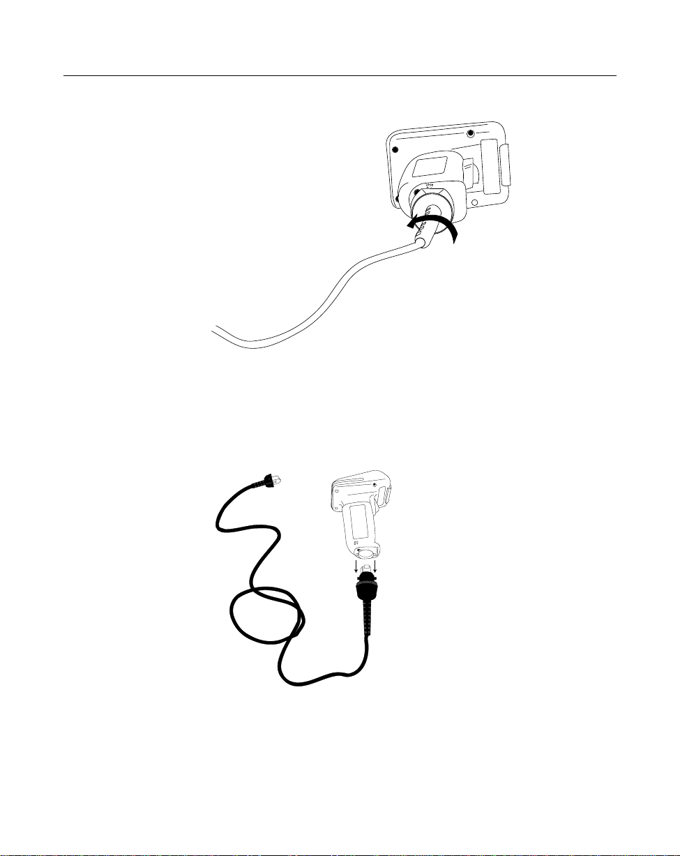
2. Twist the cable to the left to lock in place, as shown below:
Switching Cables
Different cables are required for different hosts. To change the scanner cable:
1. “Unlock” the cable by twisting to the right.
2. Pull the cable out of the receptacle on the bottom of the scanner.
3. Insert a new cable in the receptacle.
4. Twist to the left to lock the new cable in place.
1-4
Page 11
LS 1000 Product Reference Guide: Chapter 1, Introduction and Setup
Connecting to a Host
With some terminal types, the LS 100x is unable to answer host terminal polls until the
appropriate host type is selected. This may result in an error message generated by the
host. To correct this situation, select proper parameter values and initialize the host
terminal. See Chapter 4 for more information.
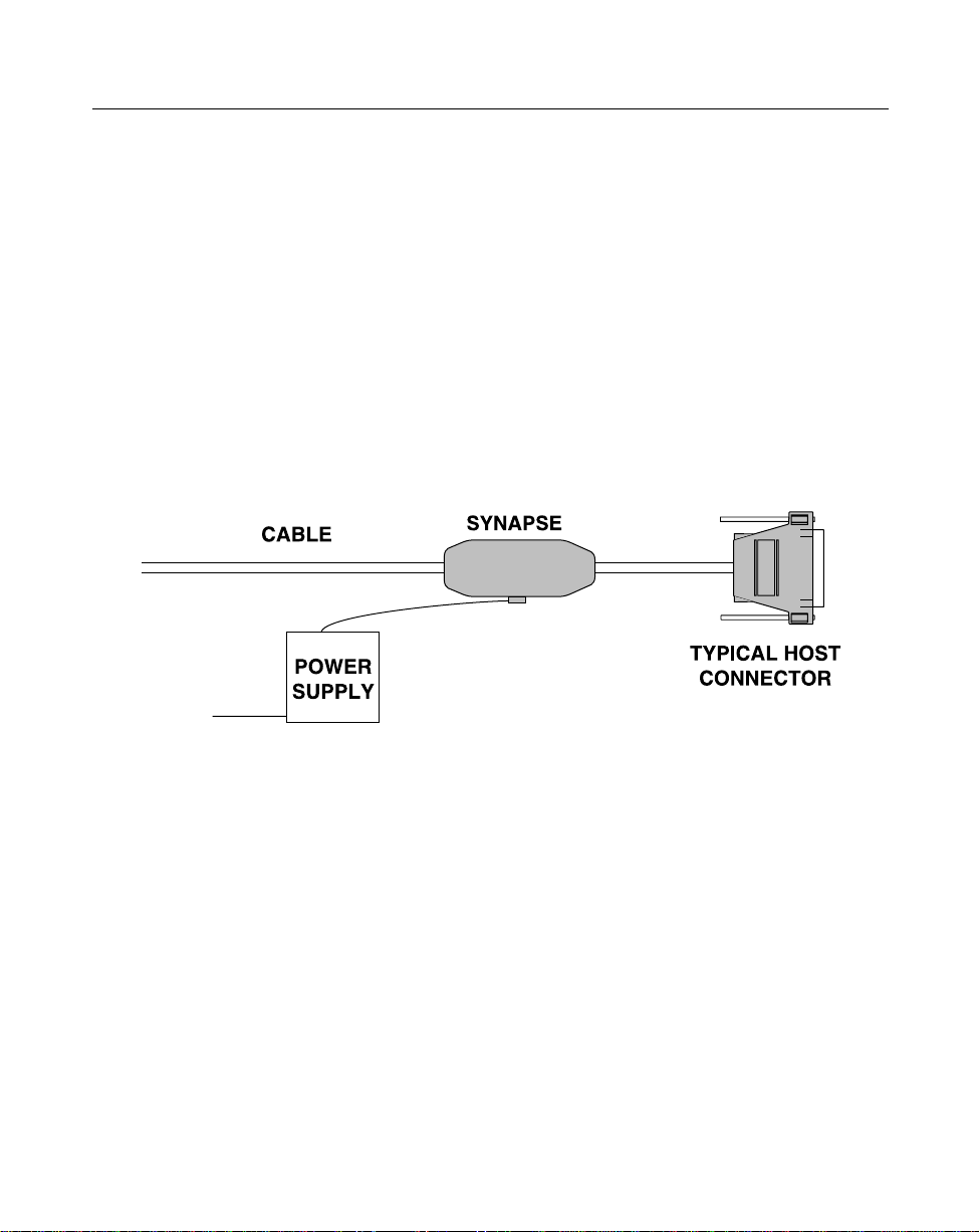
RS-232C
For external power operation with Synapse “Smart Cable”
• Plug the scanner into the Synapse “Smart Cable”.
• Connect the Synapse cable with the host connector.
• Connect the power supply to the input receptacle located on the Synapse cable.
Figure 1-1. RS-232C External Power Connection using Synapse Cable
1-5
Page 12
LS 1000 Product Reference Guide: Chapter 1, Introduction and Setup
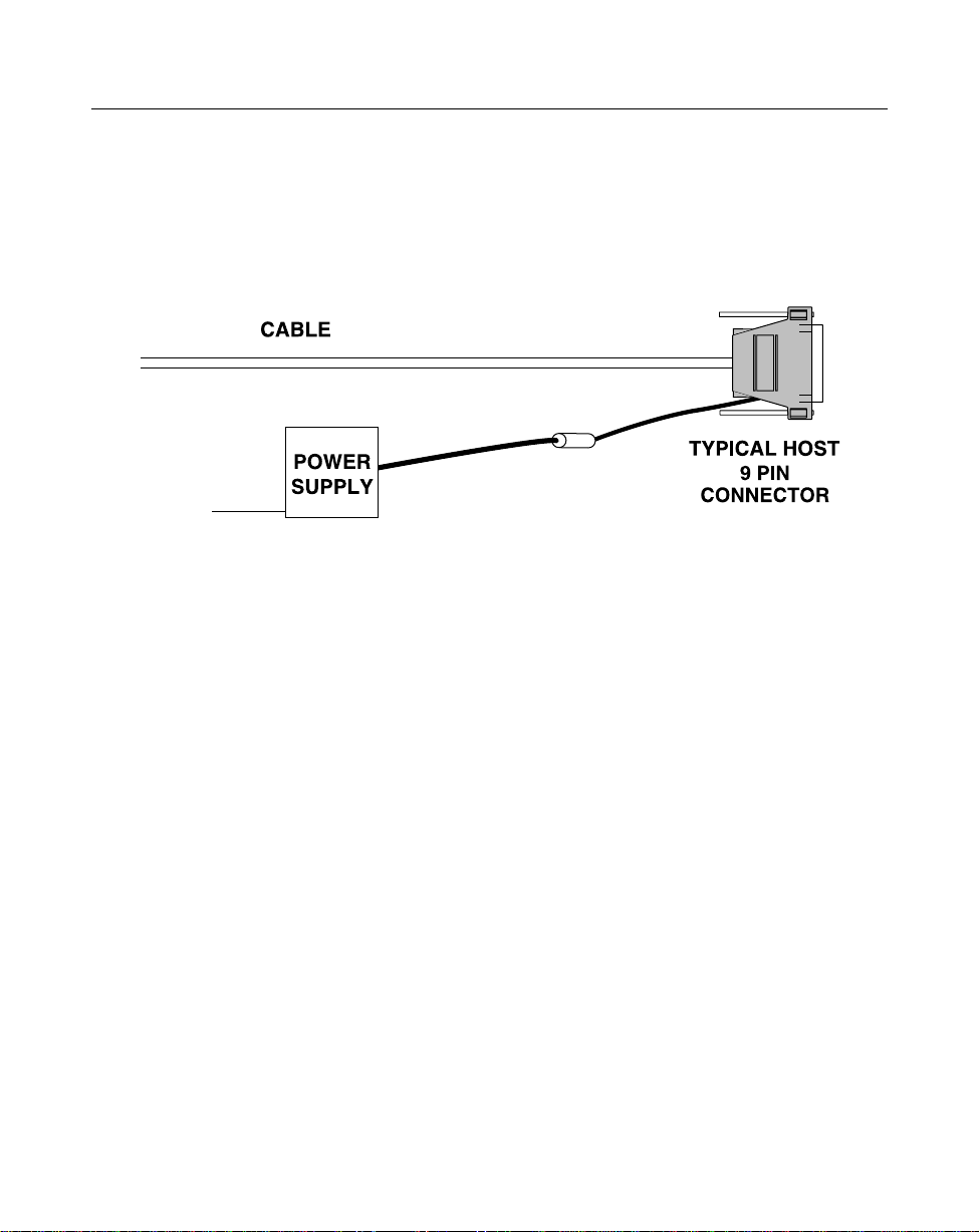
For external power operation with Flying Lead Connector
• Plug the cable into the scanner.
• Plug the Power Supply into the receptacle on the Flying Lead connector.
Figure 1-2. RS-232C External Power Connection: Flying Lead Connector to a 9-pin
Host Connector
1-6
Page 13
LS 1000 Product Reference Guide: Chapter 1, Introduction and Setup
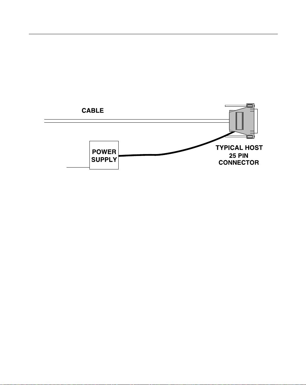
For external power operation with 25-pin Host Connector
• Plug the cable into the scanner.
• Plug the Power Supply into the receptacle on the side of the 25-pin Host
Connector
Figure 1-3. RS-232C External Power Connection: 25-pin Host Connector
1-7
Page 14
LS 1000 Product Reference Guide: Chapter 1, Introduction and Setup
RS-232C (Contd)
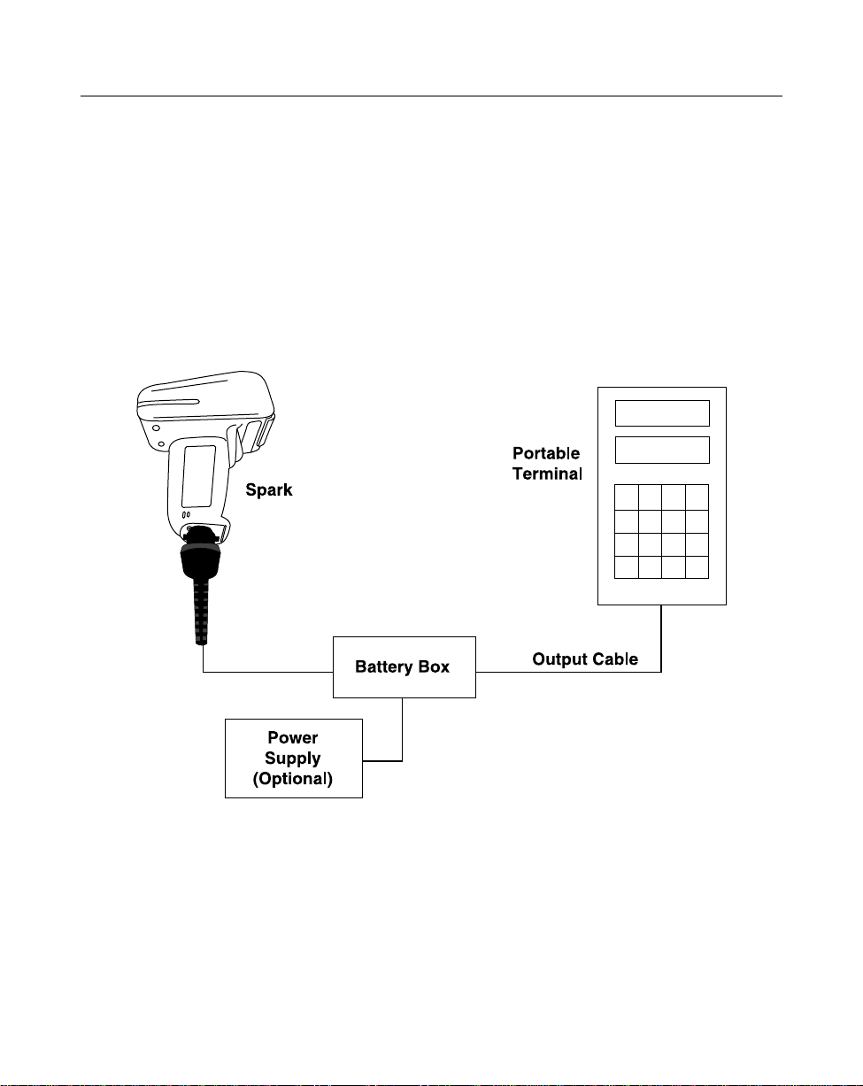
For battery operation:
• Insert a 9-volt battery into the battery box. See
• Plug the scanner's 9-pin connector at the end of the cord into one end of the
battery box.
• An output cable from the battery box connects the LS 1000 to the RS-232C
input device. Connect one end of this cable to the battery box and the other
to the appropriate port on the host device.
Battery Box Operation
.
Figure 1-4. RS-232C Operation
1-8
Page 15
LS 1000 Product Reference Guide: Chapter 1, Introduction and Setup
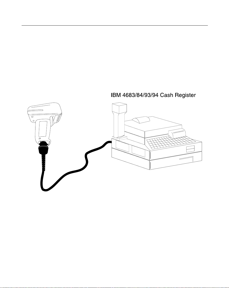
IBM 468X/9X
Plug the SDL modular connector at the end of the selected Synapse “Smart” cable into
the appropriate port (5B, 9B, 9C, 9E, or 17). Check that the connection is secure. To
install an LS 1004 on an IBM 468X/469X host:
1. Connect a synapse adaptor cable to the scanner, using the procedure described in
“Installing the Cable ” .
2. Plug the other end of the adaptor cable into the synapse cable’s female connector.
Spark
Figure 1-5. Typical System Configuration
1-9
Page 16
LS 1000 Product Reference Guide: Chapter 1, Introduction and Setup
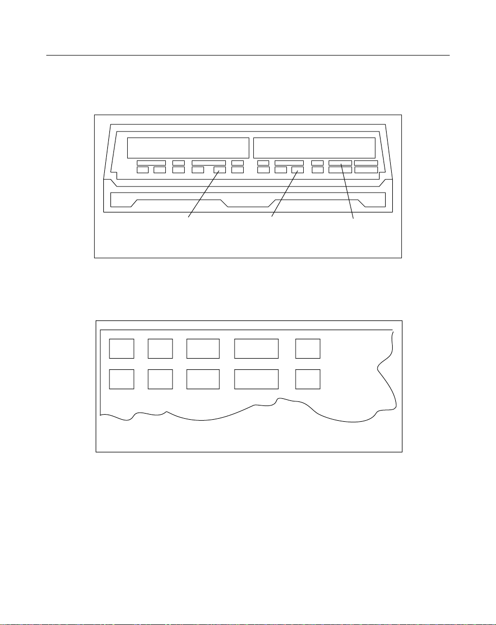
IBM 468X/9X (Contd)
PORT 5B
Figure 1-6. IBM 4683 Rear Panel with Cover Removed
9B
Figure 1-7. IBM 4684 Rear Panel with Cover Removed
5B
PORT 9B
17
PORT 17
1-10
Page 17
LS 1000 Product Reference Guide: Chapter 1, Introduction and Setup
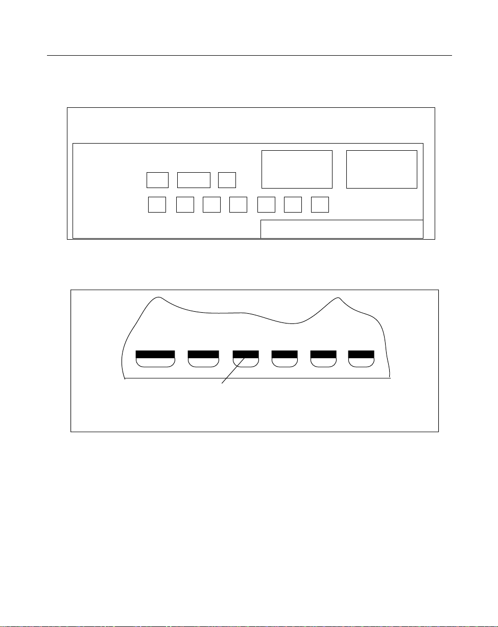
IBM 468X/9X (Contd)
5B
Figure 1-8. IBM 4693 Rear Panel with Cover Removed
IBM 4694 REAR PANEL WITH COVER REMOVED
Figure 1-9. IBM 4694 Rear Panel with Cover Removed
9C
9B
PORT 9E
Wand Emulation, OCIA, OCR, and Keyboard Wedges
A Synapse Adaptor Cable is required when connecting the LS 1004 to any of these
hosts using Synapse. See the instructions packed with the appropriate Synapse cable.
1-11
Page 18

Chapter 2 Scanning
Introduction
This chapter covers the techniques involved in scanning bar codes. Included are
specific instructions on how to hold the scanner at the appropriate angle to ensure an
accurate decode.
2-1
Page 19

LS 1000 Product Reference Guide: Chapter 2, Scanning
Ready , T est, Scan
1. Ready
Make sure all connections are secure.
2. Test
Aim the scanner away from you and press the trigger. When you press the
trigger, the scanning beam is energized. On the LS 1000, the length of time the
beam remains on depends on the controller or terminal into which it is
plugged. On the LS 1004, the scanner is energized for approximately 1 second
(default).
3. Scan
Make sure the symbol you want to scan is within the scanning range. See the
100x Decode Zone
Aim and press the trigger . On the LS 1000, the scan beam and SCAN LED lights for
3.5 seconds, or until a successful decode occurs. On the LS 1004, if you use the
scanner in default Low Power operating mode, the DECODE LED remains on until
power down (maximum of 1 second). If the unit is programmed for Continuous
power operating mode, the DECODE LED stays on until the next trigger pull.
.
LS
The scanner has read the symbol when:
• You hear a short, high tone beep (if the beeper is enabled).
• The DECODE LED lights.
2-2
Page 20
LS 1000 Product Reference Guide: Chapter 2, Scanning
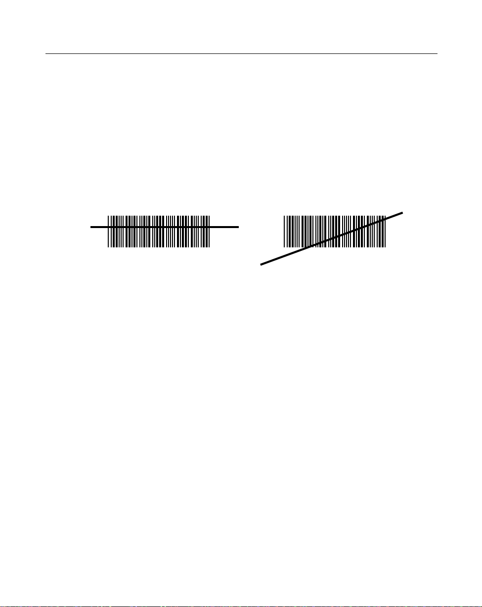
Aiming
Scan the Entire Symbol
• Your scan beam must cross every bar and space on the symbol.
• The larger the symbol, the farther away you should hold the scanner.
• Hold the scanner closer for symbols with bars that are close together.
• A short, high tone beep indicates a good decode.
RIGHT
012345
WRONG
012345
2-3
Page 21
LS 1000 Product Reference Guide: Chapter 2, Scanning
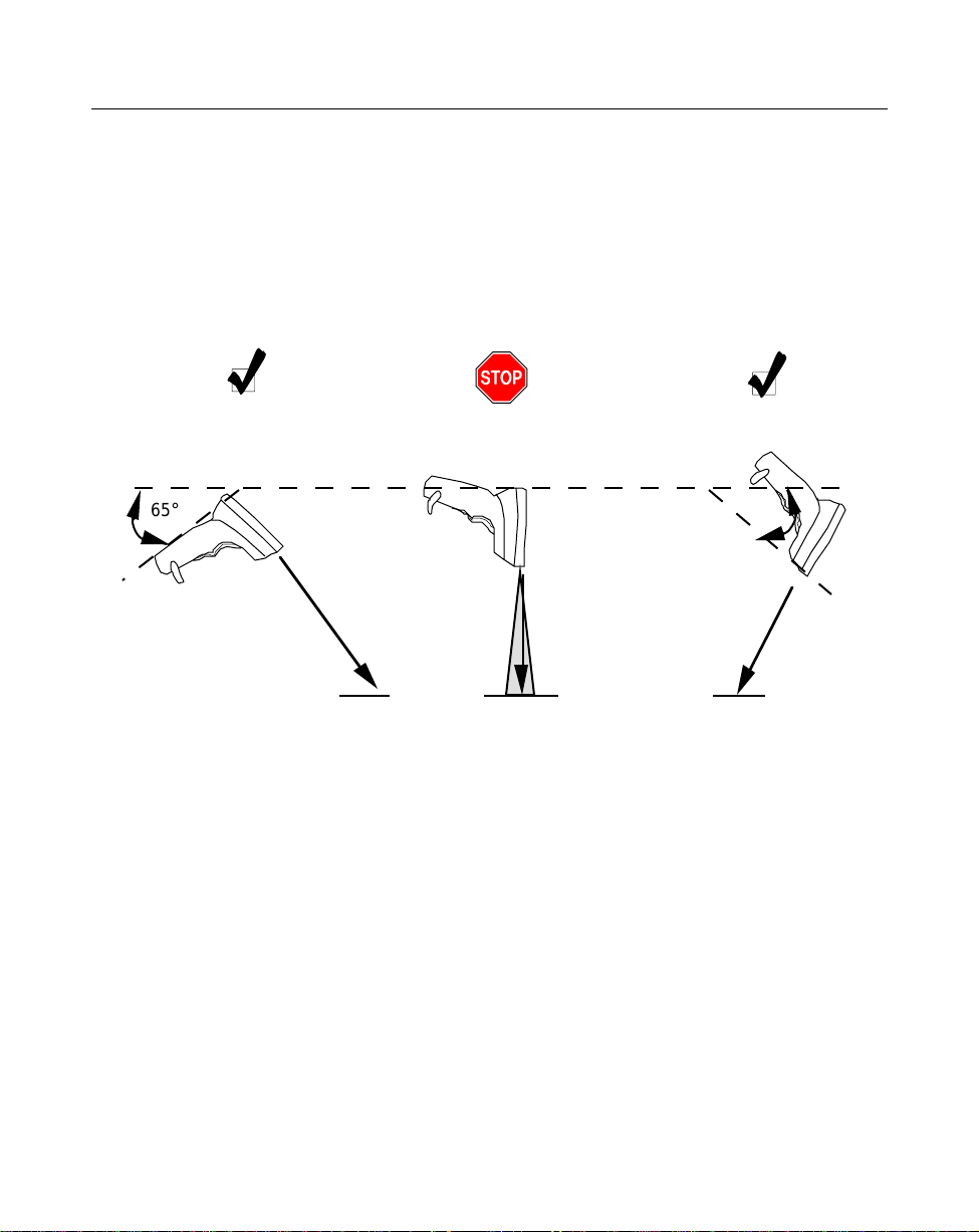
Hold at an Angle
Do not hold the scanner directly over the bar code. Laser light reflecting
directly
back
into the scanner from the bar code is known as specular reflection. This strong light can
“blind” the scanner and make decoding difficult. The area where specular reflection
occurs is known as a “dead zone”.
You can tilt the scanner up to 65° forward or back and achieve a successful decode.
Simple practice quickly shows what tolerances to work within.
1. Successful Scanning.
65° 65°
Scan
Beam
2. Possible Specular Reflection.
Bar Code
Bar Code Bar Code
Shaded area represents
dead zone (±2°)
3. Successful Scanning.
Scan
Beam
2-4
Page 22

Chapter 3
Maintenance & Specifications
Introduction
This chapter covers the suggested maintenance of the LS 100x scanner, as well as the
technical specifications, available accessories, pinouts, and beeper definitions.
3-1
Page 23

LS 1000 Product Reference Guide: Chapter 3, Maintenance and Specifications
Maintaining the LS 1000 Scanner
Battery Box Operation
When using the LS 1000 Series with a battery box, you can use either an alkaline battery
(recommended), or a nickel-cadmium rechargeable battery. Low power is signalled by
4 short, high-tone beeps, coupled with scanning interruptions. If this occurs, change or
recharge the battery as soon as possible. For battery box operation:
1. Insert a 9-volt battery into the battery box.
2. Plug the scanner’s 9-pin connector at the end of the coil cord into the end of the
battery box.
3. An output cable from the battery box connects the LS 1000 Series to the host device.
Connect one end of this cable to the battery box and the other to the appropriate
port on the host device.
Note:
Changing the Battery
• Disconnect the battery box.
• To open the battery box, push up on the flanges at one end of the pack.
• Remove the old battery.
• Insert the new or recharged 9-volt battery into the battery box. Match the
positive (+) and negative (-) terminals on the battery with the corresponding
terminals in the battery box.
Not all applications require a power supply or battery
box. The output cable depends on the wand being
replaced. See the
information.
Product Ordering Guide
for more
Recharging a Nickel-Cadmium Battery
• Remove the battery from the battery box and place it in the recharging unit (not
supplied by Symbol).
• To recharge the battery, follow the instructions supplied with the recharging
unit.
3-2
Page 24

LS 1000 Product Reference Guide: Chapter 3, Maintenance and Specifications
Maintenance
Cleaning the exit window is the only maintenance required.
• Do not allow any abrasive material to touch the window.
• Remove any dirt particles with a damp cloth.
• Wipe the window using a damp cloth, and if necessary, a non-ammonia based
detergent.
• Do not spray water or other cleaning liquids directly into the window.
3-3
Page 25

LS 1000 Product Reference Guide: Chapter 3, Maintenance and Specifications
Accessories
Required Accessories
Required accessories are listed in the
available at extra cost.
Table 3-1. LS 1000 Required Accessories
Part Number Description
ND1221 One undecoded cable
70-17422-01 LS 1000 Series Quick Reference Guide
Table 3-1. LS 1004 Required Accessories
Part Number Description
ND1223 One RS-232 Cable 9-pin female TxD pin 2, or
ND1224 One RS-232 Cable 25-pin male TxD pin 3, or
ND1225 One RS-232 Cable 25-pin TxD pin 3
ND1222 Synapse Adapter Cable
70-17422-01 LS 1000 Series Quick Reference Guide
Product Ordering Guide
. Optional accessories are
Optional Accessories
Optional accessories, listed in the
holders, which are supplied at extra cost. Additional units of standar d accessories may
also be purchased at extra cost.
Product Ordering Guide, include various stands and
3-4
Page 26

LS 1000 Product Reference Guide: Chapter 3, Maintenance and Specifications
What If...
Nothing happens when you follow the operating instructions?
You Should
• Check the system power; is there a battery in the battery box?
• Be sure the scanner is programmed for the terminal in use.
• Make sure the scanner is programmed to read the type of bar code you are
scanning.
• Check for loose cable connections.
• Check the symbol to make sure it is not defaced.
• Try scanning test symbols of the same code type.
• Be sure you are within the proper scanning range.
Symbol is decoded, but not transmitted to the host terminal?
You Should
• Be sure the proper host type is selected (See Chapter 4).
Scanned data is incorrectly displayed on the terminal?
You Should
• Make sure the system is programmed for the correct keyboard type.
• Make sure the CAPS LOCK key is off.
• Be sure the proper host is selected.
• Be sure editing options (e.g. UPC-E to UPC-A Conversion) are properly
programmed.
If after performing these checks the symbol still does not scan, contact your distributor
or call the Symbol Support Center. See Symbol Support Center for the telephone
number.
3-5
Page 27

LS 1000 Product Reference Guide: Chapter 3, Maintenance and Specifications
LS 100x Technical Specifications
LS 100x Decode Zone
In. Cm.
10 25.4
5 12.7
Scanner
0 0
5.0 mil
1.0 2.3
In.
Cm.
7.5 mil
0
2.0
0
0
5.0
13 mil
20 mil minimum element width
5
12.7
9.0
10
25.4
Depth of Field in Inches/Centimeters
Depth of field as a function of minimum element width.
Figure 3-1. LS 100x Decode Zone
5 12.7
10 25.4
15.0
15
38.1
3-6
Page 28

LS 1000 Product Reference Guide: Chapter 3, Maintenance and Specifications
Table 3-1. Technical Specifications (LS 1000)
Item Description
Power Requirements*
Discrete 4.8 to 14 VDC (max) 80 mA @ 5VDC typical
Decode Capability Transmission of decoded information will depend on the
capabilities of the attached terminal.
Beeper Operation User-selectable: Enabled, Disabled, Volume, Tone
Scan Repetition Rate 36 (± 3) scans/sec (bidirectional)
Skew Tolerance ± 65˚ from normal
Pitch ± 60˚ from normal
Decode Depth of Field See Decode Zone
Print Contrast Minimum 25% absolute dark/light differential, measured at 670 nm.
Ambient Light Immunity
Artificial Lighting
Sunlight
450 ft. candles 4844 lux
8000 ft. candles86112 lux
3-7
Page 29

LS 1000 Product Reference Guide: Chapter 3, Maintenance and Specifications
Table 3-1. Technical Specifications (LS 1000) (Continued)
Item Description
Operating Temperature 32° to 104°F0° to 40°C
Storage Temperature -40° to 140°F-40° to 60°C
Humidity 5% to 95% (non-condensing)
Durability 4-ft. drop to concrete1.2 m
Dimensions
Height
Length
Width
Laser Classifications CDRH Class II
Start-Up Time <50 msec from scan enable
Data Acquisition Time <110 msec from scan enable
Minimum Element Width 0.005 in0.127 mm
Maximum Element Width 0.020 in
4.8 in.122 mm
3.7 in.93 mm
2.4 in.60 mm
IEC 825 Class 2
3-8
Page 30

LS 1000 Product Reference Guide: Chapter 3, Maintenance and Specifications
Table 3-2. Technical Specifications (LS 1004)
Item Description
Power Requirements*
RS-232C/Synapse
Low Power
Decode Capability The LS 100x can be programmed to decode the
Beeper Operation User-selectable: Enabled, Disabled., Volume, Tone
Scan Repetition Rate 36 (± 3) scans/sec (bidirectional)
Skew Tolerance ± 65˚ from normal
4.75 to 14.5 VDC (max) 100mA @ 5VDC typical
4.75 to 14 VDC (max) 200 mA @ 5V typical
following code types: UPC/EAN, Code 39,
Code 39 Full ASCII, Code 93, Codabar,
Interleaved 2 of 5 , Code 128, EAN 128, and
Discrete 2 of 5. Set code length(s) for any linear
code type. The LS 100x can auto-discriminate
between all of the above code types except for
Code 39 and Code 39 Full ASCII.
Pitch ± 60˚ from normal
Decode Depth of Field See Decode Zone
Print Contrast Minimum 25% absolute dark/light differential, measured at
670 nm.
Ambient Light Immunity
Artificial Lighting
Sunlight
450 ft. candles 4844 lux
8000 ft. candles86112 lux
3-9
Page 31

LS 1000 Product Reference Guide: Chapter 3, Maintenance and Specifications
Table 3-2. Technical Specifications (LS 1004) (Continued)
Item Description
Operating Temperature 32° to 104°F0° to 40°C
Storage Temperature -40° to 140°F-40° to 60°C
Humidity 5% to 95% (non-condensing)
Durability 4-ft. drop to concrete1.2 m
Dimensions
Height
Length
Width
Laser Classifications CDRH Class II
Start-Up Time <50 msec from scan enable
Data Acquisition Time <110 msec from scan enable
Minimum Element Width 0.005 in0.127 mm
Maximum Element Width 0.020 in5.08 mm
4.8 in.122 mm
3.7 in.93 mm
2.4 in.60 mm
IEC 825 Class 2
*For direct host power connection, make sure the host terminal supplies sufficient
power for the specified operation. Symbol is not responsible for damage to host
equipment or system mis-operation due to an insufficient power condition.
3-10
Page 32

LS 1000 Product Reference Guide: Chapter 3, Maintenance and Specifications
Table 3-3. Pinouts - LS 1000
Pin LS 1000 Function
1 VBAT Power Supply
2 VBAT Power Supply
3 GND Ground
4 ENABLE Scan Enable
5 SOS Start of Scan
6 TRIGGER* Trigger Signal
7 DECODE Successful Decode
8 DBP Digital Bar Pattern
9 N.C. Non-Connected
10 N.C. Non-Connected
* active low
3-11
Page 33

LS 1000 Product Reference Guide: Chapter 3, Maintenance and Specifications
Table 3-4. Pinouts - LS 1004
Pin LS 1004 Function
1 Data Data Line (for
synapse)
2 VBAT Power Supply
3 GND Ground
4 RTS Request to Send (for
RS-232C)
5 RXD* Receive Data Input
(for RS-232C)
6 N.C. Non-Connected (for
RS-232C)
7 DTR Data Terminal Ready
(for RS-232C)
8 TXD* Transmit Data
Output (for RS-232C)
9 CTS Clear to Send (for RS-
232C)
10 Clock Clock Line (for
Synapse)
* active low
3-12
Page 34

LS 1000 Product Reference Guide: Chapter 3, Maintenance and Specifications
Table 3-5. Beeper Indications
Standard Use
Beeper Sequence Indication
1 Beep - short high tone A bar code symbol was decoded (if decode beeper is
enabled).
4 Beeps - long low tone A transmission error has been detected in a scanned
symbol. The last data scanned was lost. Scan the last
data again.
4 Beeps - short high tone Low power indication; no further scanning is possible.
Change or recharge battery.
3 Beeps - short high tone Power-up (continuous power mode only)
Parameter Menu Scanning
1 Beep - short high tone Appropriate menu within the scanning sequence has
been read
1 Beep - warble sound Parameter value entered successfully
2 Beeps - long low tone Parameter not entered, or incorrect sequence
performed. Scan CANCEL and restart the scanning
sequence.
3-13
Page 35

Chapter 4
Programming The LS 1004
Introduction
This chapter provides information on how to program the LS 1004 scanner. Before
programming the scanner, follow the instructions in the Appendix section of Chapter
1.
The default table, shown on the following page, illustrates the default values with
which the scanner is shipped. If the default values suit your requirements, scan the
Appendix barcode. This will set the scanner to the default parameters. Changing the
scanner’s programmable parameters is accomplished by scanning the bar codes
provided in this section.
4-1
Page 36

LS 1000 Product Reference Guide: Chapter 4, Programming the LS 1004
The following table lists the defaults for all parameters. If you wish to change any
option, scan the appropriate bar code(s)
Table 4-1. Default Table
Parameter Default
Appendix All Defaults
Appendix RS-232C
Appendix Disable
Appendix Enable
Appendix Middle
Appendix High Level
Appendix 1 second
Appendix Low Power
Appendix Disable
Appendix No Message
Appendix Disable
Appendix All
UPC/EAN
Appendix Enable
Appendix Enable
Appendix Disable
Appendix Disable
Appendix Disable
Appendix No Supplemental
Appendix System Character
Appendix Level 0
Code 128
Appendix Enable
4-2
Page 37

LS 1000 Product Reference Guide: Chapter 4, Programming the LS 1004
Table 4-1. Default Table
Parameter Default
Appendix Disable
Code 39
Appendix Enable
Appendix Disable
Appendix Disable
Appendix Enable
Code 93
Appendix Enable
I 2 of 5
Appendix Enable
Appendix 14 (length 1)
0 (length 2)
Appendix Disable
Appendix Disable
D 2 of 5
Appendix Enable
Appendix Disable
Appendix 12 (length 1)
0 (length 2)
Codabar
Appendix Enable
Appendix Disable
Appendix Disable
Data Options
Appendix Disable
4-3
Page 38

LS 1000 Product Reference Guide: Chapter 4, Programming the LS 1004
Table 4-1. Default Table
Parameter Default
Appendix None
Appendix CR/LF
RS-232C
Appendix 9600
Appendix Even
Appendix 7 Data Bits (with Parity)
Appendix Two
Appendix Enable
Appendix None
Appendix None
Appendix 0msec
4-4
Page 39

LS 1000 Product Reference Guide: Chapter 4, Programming the LS 1004
Scanning Sequence
A scanning sequence establishes a value for one parameter type. During a scanning
sequence, bar codes are scanned to select a parameter. All bar codes necessary for
programming the scanner are provided in the Appendix section of this manual.
Scanning Sequence Example
In this example, assume you want to program the scanner for all default settings except
for two parameters, Appendix and Appendix .
Since you want to keep the majority of the default settings, scan the Appendix bar
code. The default for DECODE UPC ONLY is DISABLED, but in this example, you
need it enabled. To do this, scan the DECODE UPC ONLY ENABLE bar code. You’ll
hear hi/lo/hi/low warble. The warble sound indicates that the scanner has been
successfully programmed for the selected parameter. Other beeper indications are
listed in Chapter 3.
The default for INTERCHARACTER DELAY is 0 msec, but you need it set to 2 msec.
To program the scanner for a 2msec intercharacter delay, scan the bar codes listed
below. This sequence includes a two-digit entry; single-digit entries require a leading
zero.
You’ll hear...
1. Scan INTERCHARACTER DELAY Short high tone
2. Scan 0 Short high tone
3. Scan 2 Hi/Lo/Hi/Lo warble
Errors While Scanning
Don’t worry if you make an error during a scanning sequence. If you’re scanning a
multi-step sequence, scanning CANCEL removes you from that sequence so that you
can start again.
Otherwise, simply scan the single correct bar code for the desired parameter.
4-5
Page 40

LS 1000 Product Reference Guide: Chapter 4, Programming the LS 1004
Parameter Descriptions
Refer to the Default table in the front of this chapter for the default settings for each
parameter type.
Set Parameter Defaults
Scanning the SET ALL DEF AUL TS bar code returns all parameters to the default values
listed in the Default Table.
SET ALL DEFAULTS
Host Interface Select
Scan the bar code corresponding to your host type. You must select a host type when
you first set up the scanner and whenever you change host type.
SET RS-232C HOST
SET SYNAPSE HOST
4-6
Page 41

LS 1000 Product Reference Guide: Chapter 4, Programming the LS 1004
Power On Beep Enable/Disable
This option, if selected, causes the beeper to sound at power-up (in continuous power
mode only).
Power On Beep Enable
Power On Beep Disable
Beeper after Decode
This option determines whether the beeper sounds during normal scanning. Usually,
it is desirable to operate the unit with the beeper enabled. In all cases, the beeper
operates during parameter menu scanning and indicates error conditions. See the
Appendix 3-5 section in Chapter 3.
Beeper Enable
Beeper Disable
Beeper T one
Three options are available for beeper tone (frequency); low, middle, and high.
Beeper T one Low
Beeper T one Mid
Beeper T one High
4-7
Page 42

LS 1000 Product Reference Guide: Chapter 4, Programming the LS 1004
Beeper V olume
Three options are available for beeper volume; low, middle, and high.
Beeper V olume Low
Beeper V olume Mid
Beeper V olume High
4-8
Page 43

LS 1000 Product Reference Guide: Chapter 4, Programming the LS 1004
Decode Attempt Time
This parameter sets the length of time the scanner laser beam will remain on while
attempting to scan a symbol.
0.5 seconds
1.0 seconds
1.5 seconds
2.0 seconds
2.5 seconds
3.5 seconds
4.0 seconds
4.5 seconds
5.0 seconds
5.5 seconds
3.0 seconds
6.0 seconds
4-9
Page 44

LS 1000 Product Reference Guide: Chapter 4, Programming the LS 1004
Decode Attempt Time (cont’d)
6.5 seconds
7.0 seconds
Operating Mode
This parameter determines whether or not power remains on after a decode attempt.
The LOW POWER option provides for power-down after each scan attempt, while the
CONTINUOUS option provides for power to remain on after each scan attempt.
Continuous
Low Power
Aggressive Scan Mode
This parameter is available in the continuous operation mode only. When you set this
parameter to be enabled, the scanner scans the mirror continuously, even if it does not
illuminate the laser diode.
Aggressive Scan
Enable
Aggressive Scan
Disable
4-10
Page 45

LS 1000 Product Reference Guide: Chapter 4, Programming the LS 1004
Transmit “No Decode” Message
This feature gives you the option to transmit “NR” when a symbol does not decode.
Prefixes and suffixes enabled will be appended around this character.
T ransmit “NO DECODE”
Message
Do Not Transmit “NO
DECODE” Message
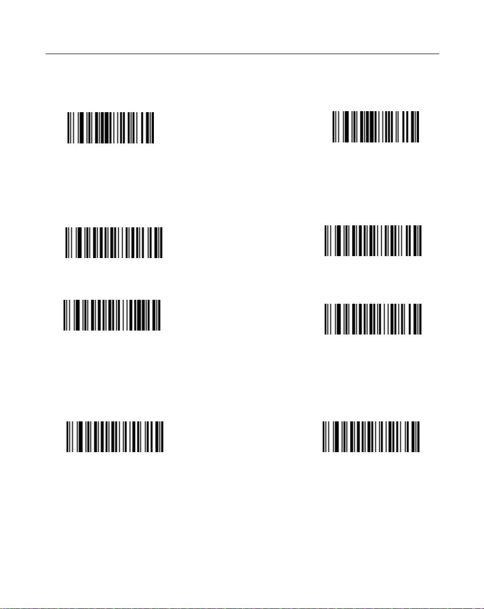
Decode Redundancy
When you select ENABLE CODABAR DECODE REDUNDANCY, a Codabar symbol
must be decoded in both directions before being accepted as a successful decode. If you
select ENABLE ALL CODE TYPES DECODE REDUNDANCY, all bar code symbols
must be decoded in both directions before being accepted as successful decodes.
Enable CODABAR
Decode Redundancy
Disable CODABAR
Decode Redundancy
Enable ALL CODE TYPES
Decode Redundancy
Disable ALL CODE
TYPES
Decode Redundancy
4-11
Page 46

LS 1000 Product Reference Guide: Chapter 4, Programming the LS 1004
Code T ypes
Selecting the ENABLE ALL CODE TYPES bar code below enables the following
symbologies:
• UPC Versions A and E (EAN 8 and 13)
• Code 39
• Interleaved 2 of 5
• Code 93
• Codabar
• Discrete 2 of 5
• Code 128
• Code 39 Full ASCII
The scanner autodiscriminates between all of the above symbologies, except for Code
39 and Code 39 Full ASCII.
Enable All Code Types Disable All Code Types
4-12
Page 47
LS 1000 Product Reference Guide: Chapter 4, Programming the LS 1004
UPC/EAN
Enable/Disable UPC/EAN
Enable UPC/EAN
Disable UPC/EAN
Transmit UPC-E/UPC-A
Select this option if decoded UPC-E or UPC-A symbols ar e transmitted with or without
the check digit.
Transmit UPC-A check dig-
it
T ransmit UPC-E check digit
Do Not Transmit
UPC-A Check Digit
Do Not Transmit
UPC-E Check Digit
Decode UPC Only (Not EAN)
If selected, this option limits the scanner’s capability to UPC versions only. It disables
EAN decode capability.
Decode UPC Only Enable Decode UPC Only Disable
4-13
Page 48

LS 1000 Product Reference Guide: Chapter 4, Programming the LS 1004
Convert UPC-E to UPC-A
Select this option to convert UPC-E (zero suppressed) decode data to UPC-A format
before transmission. After conversion, data follows UPC-A format and is affected by
UPC-A programming selections (e.g., Preamble, Check Digit).
Convert UPC-E to UPC-
A
Do Not Convert
UPC-E to UPC-A
EAN Zero Extend
This parameter adds five leading zeros to decoded EAN-8 symbols to make them
compatible in format to EAN-13 symbols.
Enable EAN Zero Ex-
tend
Disable EAN Zero Ex-
tend
4-14
Page 49

LS 1000 Product Reference Guide: Chapter 4, Programming the LS 1004
Decode UPC/EAN Supplemental
This option is used to select whether UPC/EAN is decoded with or without
supplemental characters, or whether the unit will autodiscriminate between the two.
Supplementals are additionally appended characters, according to specific code format
conventions (e.g., UPC A+2, UPC E+2, EAN 8+5). If UPC/EAN with supplemental
characters 2-digit or 5-digit only is selected, UPC/EAN symbols without supplemental
characters won’t be decoded. If UPC/EAN without supplemental characters is
selected and the scanner is presented with a UPC/EAN plus supplemental symbol, the
UPC/EAN will be decoded and the supplemental characters will be ignored. If
autodiscrimination is chosen, the scanner will, after additional processing to ensure a
good decode, transmit either. If UPC/EAN with supplemental characters is selected,
UPC/EAN without supplemental characters is ignored.
Decode UPC/EAN
Supplementals
Decode UPC/EAN 2-digit
Supplementals Only
Ignore UPC/EAN
Supplementals
Autodiscriminate UPC/
EAN Supplementals
Decode UPC/EAN 5- digit
Supplementals Only
4-15
Page 50

LS 1000 Product Reference Guide: Chapter 4, Programming the LS 1004
UPC A and E Preamble(s)
Three options are available for the lead-in characters for decoded UPC-A or UPC-E
symbols transmitted to the host device. Select one preamble for UPC-A decodes and
one for UPC-E decodes. These lead-in characters are considered part of the symbol
itself. The three options are:
• a system character only
• the country code and system character
• no preamble
The system character is the digit printed to the extreme left of a UPC symbol. The
country code for UPC is always zero, and it cannot be transmitted without the system
character .
UPC-A Pream-
None
System Character
System Character
and
Country Code
UPC-E Pream-
None
System Character
System Character
and
Country Code
4-16
Page 51

LS 1000 Product Reference Guide: Chapter 4, Programming the LS 1004
UPC/EAN Security Level
The scanner offset four levels of decode security for UPC/EAN bar codes. Increasing
levels of security are provided for decreasing levels of bar code quality. There is an
inverse relationship between security and scanner aggressiveness, so be sure to choose
only that level of security necessary for any given application.
Security Level 0 - This is the default setting which allows the scanner to operate in its
most aggressive state, while providing sufficient security in decoding in spec UPC/
EAN bar codes.
Security Level 1 - As bar code quality levels diminish, certain characters become prone
to mis-decodes before others (i.e., 1, 2, 7, 8). If you are experiencing mis-decodes of
poorly printed bar codes, and the mis-decodes are limited to these characters, select
this security level.
Security Level 2 - If you are experiencing mis-decodes on poorly printed bar codes, and
the mis-decodes are not limited to characters 1, 2, 7 and 8, select this security level.
UPC/EAN Security
Level 0
UPC/EAN Security
Level 1
UPC/EAN Security
Level 2
4-17
Page 52

LS 1000 Product Reference Guide: Chapter 4, Programming the LS 1004
Code 128
Enable/Disable Code 128
Enable CODE 128
Disable CODE 128
Send CODE 128 Function Character
If selected, CODE 128 function characters are sent as:
• FN1=0X1D
• FN2=0X81
• FN3=0X82
• FN4=0X83
This option will be enabled when data format is 8 bits. Even if this option is disabled
or data format is 7 bits, FN1 will still be set as 0X1D, unless FN1 is in the first or second
character in a bar code message.
Transmit CODE 128
Function Character
Enabled
Transmit CODE 128
Function Character
Disabled
4-18
Page 53

LS 1000 Product Reference Guide: Chapter 4, Programming the LS 1004
Code 39
Enable/Disable Code 39
Enable Code 39 Disable Code 39
CODE 39 Modulo 43 Check
When enabled, this parameter checks the integrity of a CODE 39 symbol to ensure it
complies with specified algorithms.
Verify Code 39
Check Digit
Do Not V erify Code
Transmit CODE 39 Check Digit
When enabled, CODE 39 Check Digit will be sent to the host.
Transmit CODE 39
Check Digit Enable
Check Digit Disable
Enable/Disable Code 39 Full ASCII
Enable Code 39
Full ASCII
39 Check Digit
Transmit CODE 39
Disable Code 39
Full ASCII
4-19
Page 54

LS 1000 Product Reference Guide: Chapter 4, Programming the LS 1004
Code 93
Enable/Disable Code 93
Enable Code 93
Disable Code 93
4-20
Page 55

LS 1000 Product Reference Guide: Chapter 4, Programming the LS 1004
Interleaved 2 of 5
Enable/Disable Code I 2 of 5
Enable Code I 2 of 5 Disable Code I 2 of 5
Fixed Lengths for Code I 2 of 5
Select one or two lengths for the Interleaved 2 of 5 codes. If you set both Length 1 and
Length 2 to 0, the scanner can read any length within 36 characters. It is recommended
that you set the I 2 of 5 modulus 10 check to enabled when you set both Length 1 and
Length 2 to 0.
If any default setting is in effect and is an appropriate length, it need not be reset.
Length 1 may range from 00-36 and Length 2 may range from 00-36.
I 2 of 5 Length 1
(RANGE00-36)
I 2 OF 5 Length 2
(RANGE 00-36)
4-21
Page 56

LS 1000 Product Reference Guide: Chapter 4, Programming the LS 1004
Fixed Lengths for Code 2 of 5 (cont’d)
0 1
2
4
6
8
CANCEL
3
5
7
9
4-22
Page 57

LS 1000 Product Reference Guide: Chapter 4, Programming the LS 1004
I 2 of 5 Modulo 10 Check
When enabled, this parameter checks the integrity of a Interleaved 2 of 5 symbol to
ensure it complies with specific algorithms.
I 2of 5 Modulo 10
Check Digit Enable
I 2of 5 Modulo 10
Check Digit Disable
ITF14/EAN13 Conversion
This feature converts a 14-character I 2 of 5 code into EAN13, and transmits to the host
as EAN13. In order to accomplish this, the I 2 of 5 code must be enabled, one length
(either LENGTH 1 or LENGTH 2) must be set to 14, the code must have a leading zero
and proper trailing check digit.
ITF-14/EAN-13 Conver-
sion
ITF-14/EAN-13 Conversion
Disable
4-23
Page 58

LS 1000 Product Reference Guide: Chapter 4, Programming the LS 1004
Discrete 2 of 5
Enable/Disable D 2 of 5
Enable Code D 2 of Disable Code D 2 of
D 2 of 5 Modulo 10 Check
When enabled, this parameter checks the integrity of a Discrete 2 of 5 symbol to ensure
it complies with specific algorithms.
D 2 of 5 Modulo 10
Check Digit Enable
D 2 of 5 Modulo 10 Check
Digit Disable
Fixed Lengths for Code 2 of 5
Select one or two lengths for the Discrete 2 of 5 codes. If you set the both of them
(Length 1 and Length 2) to 0, the scanner can read any length within 36 characters. It is
recommended that you set the D 2 of 5 modulus 10 check to enabled when you set both
Length 1 and Length 2 to 0.
If any default setting is in effect and is an appropriate length, it need not be reset.
Length 1 may range from 00-36 and Length 2 may range from 00-36
D 2 of 5 Length 1
(RANGE 00-36)
D 2 OF 5 Length 2
(Range 00-36)
4-24
Page 59

LS 1000 Product Reference Guide: Chapter 4, Programming the LS 1004
Fixed Lengths for Code 2 of 5 (cont’d)
0 1
2
4
6
8
CANCEL
3
5
7
9
4-25
Page 60

LS 1000 Product Reference Guide: Chapter 4, Programming the LS 1004
Codabar
Enable/Disable Codabar
Enable Codabar Disable Codabar
CLSI Editing
Use this parameter to insert a space after the 1st, 5th, and 10th characters of a 14character Codabar symbol. This symbol length includes start and stop characters.
Enable CLSI Editing Disable CLSI Editing
NOTIS Editing
This option strips the start and stop characters from decoded Codabar symbols.
Enable NOTIS Editing Disable NOTIS Editing
4-26
Page 61

LS 1000 Product Reference Guide: Chapter 4, Programming the LS 1004
Data Options
Transmit Code ID Character
A code ID character identifies the code type of a scanned bar code. This may be useful
when the scanner is decoding more than one code type. In addition to any singlecharacter prefixes already selected, the code ID character is appended as a prefix to the
decode. The code ID characters are:
ID Character Meaning
A UPC-A, UPC-E, EAN-13, EAN-8
B Code 39
C Codabar
D Code 128
E Code 93
F Interleaved 2 of 5
G Discrete 2 of 5 or Discrete 2 of 5 IATA
Transmit Code ID Charac-
ter
Do Not Transmit Code ID
Character
4-27
Page 62

LS 1000 Product Reference Guide: Chapter 4, Programming the LS 1004
Prefix
The scanner adds one of the following start-of-text characters to transmitted data.
• None
• Start-of-text (STX)
• One user-defined prefix (can be any ASCII character) See the ASCII Character
Table in Appendix A for more information.
Prefix None
Prefix STX
User’s Choice Prefix Character
4-28
Page 63

LS 1000 Product Reference Guide: Chapter 4, Programming the LS 1004
Suffix
• Select one or two end-of-text characters to be added to transmitted data.
• None
• CR (Carriage Return) - Returns the cursor to the same position on the line after
each decode.
• LF (Line Feed) - Moves the cursor down a line after each decode.
• CR & LF - Allow you to select where the cursor on a display terminal returns to
after it displays each decoded symbol. Selecting both CR and LF returns the
cursor to the same position on successive lines after each decode. If you select no
control code, the cursor remains where it stopped after the last transmission.
• HT (Horizontal Tab) - Moves the cursor one tab space.
• End -of-text <ETX> - One or two characters, user-defined. Refer to the ASCII
Character table in Appendix A for more information.
Suffix None
Suffix CR
Suffix LF
User’s Choice Suf-
fix Character 1
Suffix ETX
Suffix CR/LF
Suffix HT
User’s Choice Suffix
Character 2
4-29
Page 64

LS 1000 Product Reference Guide: Chapter 4, Programming the LS 1004
Prefix/Suffix V alues
0 1
2
4
6 7
8
3
5
9
CANCEL
4-30
Page 65

LS 1000 Product Reference Guide: Chapter 4, Programming the LS 1004
RS-232C
Baud Rate
Baud Rate is the number of bits of data transmitted per second. The unit’s baud rate
setting should match the data rate setting of the host device. If not, data may not reach
the host device, or may reach it in distorted form.
300
600
1200
2400
4800
9600
19200
4-31
Page 66

LS 1000 Product Reference Guide: Chapter 4, Programming the LS 1004
Parity
A parity check bit is the most significant bit of each ASCII coded character . If you select
ODD parity, the parity bit will have a value of 0 or 1, based on data, to ensure that an
odd number of 1 bits are contained in the coded character.
If you select EVEN parity , the parity bit will have a value, 0 or 1, to ensure that and even
number of 1 bits are contained in the coded character.
If you select MARK parity, the parity bit will always be 1.
If you select SPACE parity, the parity bit will always be 0.
Select the parity type according to the host device requirements.
ODD EVEN
MARK
SPACE
NONE
4-32
Page 67

LS 1000 Product Reference Guide: Chapter 4, Programming the LS 1004
Data Format
This parameter sets the transmit data format. The options are:
• 7 Data Bits (With Parity) (default)
• 8 Data Bits (With Parity)
• 8 Data Bits (Without Parity)
7-Bit
8-Bit
Stop Bit Select
The stop bit(s) at the end of each transmitted character marks the end of transmission
of one character and prepares the receiving device for the next character in the serial
data stream. The number of stop bits (one or two) selected depends on the number the
receiving terminal is programmed to accommodate. Set the number of stop bits to
match host device requirements.
1 STOP BIT 2 STOP BITS
Check Parity
This option determines whether the parity of received characters is checked. The type
of parity used is selectable through the PARITY parameter.
Check Parity of Re-
ceive Data Enable
Check Parity of Re-
ceive Data Disable
4-33
Page 68

LS 1000 Product Reference Guide: Chapter 4, Programming the LS 1004
Hardware Handshaking
Hardware handshaking allows you to check the readiness of the receiving device
before data is transmitted. If the receiving device is periodically occupied with other
tasks, hardware handshaking is needed to prevent loss of transmitted data.
Select whether the scanned data is to be transmitted as soon as it is available or whether
transmission should follow the RTS/CTS procedure.
None RTS/CTS
4-34
Page 69

LS 1000 Product Reference Guide: Chapter 4, Programming the LS 1004
Software Handshaking
This parameter offers control of the data transmission process in addition to, or instead
of, that offered by hardware handshaking. These options may be combined; for
example, ACK/NAK with ENQ.
• No software handshaking
None
• ACK/NAK only
The ACK/NAK option checks the success or failure of transmission. The scanner
expects one of the following host responses after a data transmission:
<ACK> acknowledges a valid and successful transmission.
<NAK> indicates a problem with the transmission.
Whenever a NAK is received, the unit retransmits the same data and awaits an
ACK/NAK response. After three unsuccessful attempts to transmit the same
data, the scanner aborts any further communication attempts of that message.
ACK/NAK
• ENQ ONLY
The ENQ option needs the host to request data before it is transmitted to the host.
This ensures that data transmission occurs only when the host is ready to receive.
When you select the wait for ENQ option, the scanner waits for an ENQ from the
host before it transmits data; otherwise, the unit transmits data without waiting
for an ENQ character from the host. W ith ENQ enabled, the scanner must receive
an ENQ from the host within a 2-second period after the last activity, or a
4-35
Page 70

LS 1000 Product Reference Guide: Chapter 4, Programming the LS 1004
transmission error occurs.
ENQ Only
• ACK/NAK with ENQ
This option combines both handshaking options.
ACK/NAK with ENQ
4-36
Page 71

LS 1000 Product Reference Guide: Chapter 4, Programming the LS 1004
Hardware and Software Handshaking Sequence
HARDWARE HANDSHAKING
HANDSHAKING LINES USED
UNIT ASSERTS REQUEST-TO-SEND LINE.
HOST RESPONDS BY ASSERTING CLEAR-TO-SEND LINE.
SOFTWARE HANDSHAKING
YES
WAIT FOR ENQ CHARACTER
TO BE RECEIVED FROM HOST
SYMBOL IS DECODED
RTS AND CTS
NOYES
NO REPONSE.
AFTER 2 SECONDS, THE UNIT
BEEPS 4 TIMES TO INDICATE
A TRANSMISSION ERROR.
ENQ SWITCH ON?
NO
NO REPONSE.
AFTER 2 SECONDS, THE UNIT
BEEPS 4 TIMES TO INDICATE
A TRANSMISSION ERROR.
DATA IS TRANSMITTED.
ACK/NAK SWITCH ON?
WAIT FOR ACK OR NAK RESPONSE FROM HOST
ACK RESPONSE?
TRY 3 TIMES?
NO
NO
,
YES
4 LONG BEEPS
YES
4-37
YES
NO REPONSE.
AFTER 2 SECONDS, THE UNIT
BEEPS 4 TIMES TO INDICATE
A TRANSMISSION ERROR.
FINISHED
NO
Page 72

LS 1000 Product Reference Guide: Chapter 4, Programming the LS 1004
Communications Delays and Time-Outs (Intercharacter Delay)
Selecting the intercharacter delay gives the host system time to service its receiver and
perform other tasks between characters. Select from no delay to a 99 msec. delay
between transmission of each character.
Intercharacter Delay
4-38
Page 73

LS 1000 Product Reference Guide: Chapter 4, Programming the LS 1004
Intercharacter Delay Values (cont’d)
0 1
2
4
6
8
3
5
7
9
CANCEL
4-39
Page 74

Chapter 5 Glossary
ASCII - American Standard Code for Information Interchange. A 7 bit code
representing 128 letters, numerals, punctuation marks, and control
characters. It is a standard data transmission code in the U.S.
BIT - Binary digit. One bit is the basic unit of binary information. Generally,
eight consecutive bits compose one byte of data. The pattern of 0 and 1 values
within the byte determines its meaning.
BOOKLAND EAN - A specially-formatted European Article Numbering
symbol with 13 characters (EAN-13), the first 3 of which are “978”.
BYTE - On an addressable boundary, eight adjacent binary digits (0 and 1)
combined in a pattern to represent a specific character or numeric value. Bits
are numbered from the right, 0 thr ough 7, with bit 0 the low-order bit. One byte
in memory can be used to store one ASCII character.
CDRH - Center for Devices and Radiological Health. A federal agency
responsible for regulating laser product safety. This agency specifies various
laser operation classes based on power output during operation.
CHECK DIGIT - A digit used to verify a correct symbol decode. The scanner
inserts the decoded data into an arithmetic formula and checks that the
resulting number matches the encoded check digit. Check digits are required
for UPC but are optional for other symbologies. Using check digits decreases
the chance of substitution errors when a symbol is decoded.
CODABAR - A discrete self-checking code with a character set consisting of
digits 0 to 9 and six additional characters: (- $ : / , +).
CODE 128 - A high density symbology which allows the controller to encode
all 128 ASCII characters without adding extra symbol elements.
5-1
Page 75

LS 1000 Series Product Reference Guide
CODE 3 OF 9 (CODE 39) - A versatile and widely used alphanumeric bar code
symbology with a set of 43 character types, including all uppercase letters,
numerals from 0 to 9, and 7 special characters (- . / + % $ and space). The code
name is derived from the fact that 3 of 9 elements representing a character are
wide, while the remaining 6 are narrow.
CODE 93 - An industrial symbology compatible with Code 39 but offering a
full character ASCII set and a higher coding density than Code 39.
CONTINUOUS SYMBOLOGY - A bar code or symbol in which all spaces
within the symbol are parts of characters. There are no inter character gaps in a
continuous code. The absence of gaps allows for greater information density.
DECODE - To recognize a bar code symbology (e.g., UPC/EAN) and then
analyze the content of the specific bar code scanned.
DECODE ALGORITHM - A decoding scheme that converts pulse widths into
data representation of the letters or numbers encoded within a bar code
symbol.
DISCRETE SYMBOLOGY - A bar code or symbol in which the spaces
between characters (intercharacter gaps) are not part of the code.
DISCRETE 2 OF 5 - A binary bar code symbology r epresenting each character
by a group of five bars, two of which are wide. The location of wide bars in the
group determines which character is encoded; spaces are insignificant. Only
numeric characters (0 to 9) and START/STOP characters may be encoded.
EAN - European Article Number. This European/International version of the
UPC provides its own coding format and symbology standards. Element
dimensions are specified metrically. EAN is used primarily in retail.
HOST COMPUTER - A computer that serves other terminals in a network,
providing such services as computation, database access, supervisory
programs, and network control.
IEC - International Electrotechnical Commission. This international agency
regulates laser safety by specifying various laser operation classes based on
power output during operation.
5-2
Page 76

Glossary
IEC CLASS I (IEC 825 Class I) - This is the lowest power IEC laser
classification. Conformity is ensured through a software restriction of 25
seconds of laser operation within any 100 second window and an automatic
laser shutdown if the scanner's oscillating mirror fails.
INTERCHARACTER GAP - The space between two adjacent bar code
characters in a discrete bar code.
INTERLEAVED BAR CODE - A bar code in which characters are paired
together , using bars to repr esents the first character and the intervening spaces
to represent the second.
INTERLEAVED 2 OF 5 - A binary bar code symbology repr esenting character
pairs in groups of five bars and five interleaved spaces. Interleaving provides
for greater information density. The location of wide elements (bar/spaces)
within each group determines which characters are encoded. This
continuous code type uses no intercharacter spaces. Only numeric (0 to 9)
and START/ STOP characters may be encoded.
LASER - An acronym for Light Amplification by Stimulated Emission of
Radiation. The laser is an intense light source. Light from a laser is all the same
frequency, unlike the output of an incandescent bulb. Laser light is typically
coherent and has a high energy density.
LASER DIODE - A semiconductor type of laser connected to a power source
to generate a laser beam. This laser type is a compact source of coherent light.
PARAMETER - A variable that can have different values assigned to it.
PROGRAMMING MODE - The state in which a scanner is configured for
parameter values. See SCANNING MODE.
QUIET ZONE - A clear space, containing no dark marks, which precedes the
start character of a bar code symbol and follows the stop character.
REDUNDANCY - A decoding method which requires a bar code be
recognized redundantly on a number of sweeps of the scan beam before a
decode is declared. While slowing the time-to-decode, redundancy can help
lower the possibility of a mis-decode of poorly printed symbols.
5-3
Page 77

LS 1000 Series Product Reference Guide
SCANNER - An electronic device used to scan bar code symbols and pr oduce
a digitized pattern that corresponds to the bars and spaces of the symbol. Its
three main components are:
1. Light source (laser or photoelectric cell) - illuminates a bar code.
2. Photodetector - registers the difference in reflected light (more light
reflected from spaces).
3. Signal conditioning circuit - transforms optical detector output into a
digitized bar pattern.
SCANNING MODE - The scanner is energized, programmed, and ready to
read a bar code.
SCANNING SEQUENCE - A method of programming or configuring
parameters for a bar code reading system by scanning bar code menus.
SELF-CHECKING CODE - A symbology that uses a checking algorithm to
detect encoding errors within the characters of a bar code symbol.
START/STOP CHARACTER - A pattern of bars and spaces that provides the
scanner with start and stop reading instructions and scanning direction. The
start and stop characters are normally to the left and right margins of a
horizontal code.
SYMBOL - A scannable unit that encodes data within the conventions of a
certain symbology, usually including start/stop characters, quiet zones, data
characters, and check characters.
SYMBOLOGY - The structural rules and conventions for representing data
within a particular bar code type (e.g. UPC/EAN, Code 39).
UPC - Universal Product Code. A r elatively complex numeric symbology . Each
character consists of two bars and two spaces, each of which can be any of
four widths. The standard symbology for retail food packages in the United
States.
5-4
Page 78

Chapter 6 ASCII Character Set
ASCII Character Set
Table 6-1. ASCII Character Set
ASCII
Value
000 %U CTRL 2 024 $X CTRL X
001 $A CTRL A 025 $Y CTRL Y
002 $B CTRL B 026 $Z CTRL Z
003 $C CTRL C 027 %A CTRL [
004 $D CTRL D 028 %B CTRL \
005 $E CTRL E 029 %C CTRL ]
006 $F CTRL F 030 %D CTRL 6
007 $G CTRL G 031 %E CTRL 008 $H CTRL H 032 Space Space
009 $I CTRL I 033 /A !
010 $J CTRL J 034 /B ‘
011 $K CTRL K 035 /C #
012 $L CTRL L 036 /D $
013 $M CTRL M 037 /E %
014 $N CTRL N 038 /F &
015 $O CTRL O 039 /G ‘
016 $P CTRL P 040 /H (
017 $Q CTRL Q 041 /I )
018 $R CTRL R 042 /J *
019 $S CTRL S 043 /K +
020 $T CTRL T 044 /L ,
Full ASCII
Code 39
Encode Char.
Keystroke ASCII
Value
Full ASCII
Code 39
Encode Char
Keystroke
6-1
Page 79

PPT 4600 Product Reference Guide: Getting Started
Table 6-1. (Continued) ASCII Character Set
021 $U CTRL U 045 - 022 $V CTRL V 046 . .
023 $W CTRL W 047 / /
ASCII
Value
048 0 0 073 I I
049 1 1 074 J J
050 2 2 075 K K
051 3 3 076 L L
052 4 4 077 M M
053 5 5 078 N N
054 6 6 079 O O
055 7 7 080 P P
056 8 8 081 Q Q
057 9 9 082 R R
058 /Z : 083 S S
059 %F ; 084 T T
060 %G < 085 U U
061 %H = 086 V V
062 %I > 087 W W
063 %J ? 088 X X
064 %V @ 089 Y Y
065 A A 090 Z Z
066 B B 091 %K [
067 C C 092 %L \
068 D D 093 %M ]
069 E E 094 %N ^
070 F F 095 %O _
071 G G 096 %W ‘
Full ASCII
Code 39
Encode Char.
Keystroke ASCII
Value
Full ASCII
Code 39
Encode Char
Keystroke
6-2
Page 80

PPT 4600 Product Reference Guide: Getting Started
Table 6-1. (Continued) ASCII Character Set
072 H H 097 +A a
ASCII
Value
098 +B b 113 +Q q
099 +C c 114 +R r
100 +D d 115 +S s
101 +E e 116 +T t
102 +F f 117 +U u
103 +G g 118 +V v
104 +H h 119 +W w
105 +I i 120 +X x
106 +J j 121 +Y y
107 +K k 122 +Z z
108 +L l 123 %P {
109 +M m 124 %Q |
110 +N n 125 %R }
111 +O o 126 %S ~
112 +P p 127 Undefined
Full ASCII
Code 39
Encode Char.
Keystroke ASCII
Value
Full ASCII
Code 39
Encode Char
Keystroke
6-3
Page 81

Appendix A Errata
Table A-1. ASCII Character Set
264 ALT 2 275 ALT K 286 ALT V
265 ALT A 276 ALT L 287 ALT W
266 ALT B 277 ALT M 288 ALT X
267 ALT C 278 ALT N 289 ALT Y
268 ALT D 279 ALT O 290 ALT Z
269 ALT E 280 ALT P 291 ALT [
270 ALT F 281 ALT Q 292 ALT \
271 ALT G 282 ALT R 293 ALT ]
272 ALT H 283 ALT S 294 ALT 6
273 ALT I 284 ALT T 295 ALT 274 ALT J 285 ALT U
Misc. Key Keystroke Misc. Key Keystroke Misc. Key Keystroke
301 PA 1 309 CMD 7 317 °
302 PA 2 310 CMD 8 318 1/2
303 CMD 1 311 CMD 9 319 ¶
304 CMD 2 312 CMD 10 320 §
305 CMD 3 313 ¥ 321 |
306 CMD 4 314 £ 322 0/00
307 CMD 5 315 ¤
308 CMD 6 316 ¬
A-1
Page 82

LS 1000 Product Reference Guide: Appendix A, Errata Shee
PF Keys Keystroke PF Keys Keystroke PF Keys Keystroke
401 PF 1 409 PF 9 417 PF 17
402 PF 2 410 PF 10 418 PF 18
403 PF 3 411 PF 11 419 PF 19
404 PF 4 412 PF 12 420 PF 20
405 PF 5 413 PF 13 421 PF 21
406 PF 6 414 PF 14 422 PF 22
407 PF 7 415 PF 15 423 PF 23
408 PF 8 416 PF 16 424 PF 24
F Keys Keystroke F Keys Keystroke F Keys Keystroke
501 F 1 514 F 14 527 F 27
502 F 2 515 F 15 528 F 28
503 F 3 516 F 16 529 F 29
504 F 4 517 F 17 530 F 30
505 F 5 518 F 18 531 F 31
506 F 6 519 F 19 532 F 32
507 F 7 520 F 20 533 F 33
508 F 8 521 F 21 534 F 34
509 F 9 522 F 22 535 F 35
510 F 10 523 F 23 536 F 36
511 F 11 524 F 24 537 F 37
512 F 12 525 F 25 538 F 38
513 F 13 526 F 26 539 F 39
A-2
Page 83

LS 1000 Product Reference Guide: Appendix A, Errata Sheet
Numeric
Keypad
642 * 649 1 656 8
643 + 650 2 657 9
644 Undefined 651 3 658 Enter
645 - 662 4 659 Num Lock
646 . 663 5 660 00
647 / 664 6
648 0 665 7
Extended
Keypad
701 Break 708 Backspace 715 Up Arrow
702 Delete 709 Tab 716 Dn Arrow
703 Pg Up 710 Print Screen 717 Left Arrow
704 End 71 1 Insert 718 Right Arrow
705 Pg Dn 712 Home 719 Back Tab
706 Pause 713 Enter
707 Scroll Lock 714 Escape
Keystroke Numeric
Keypad
Keystroke Extended
Keypad
Keystroke Numeric
Keypad
Keystroke Extended
Keypad
Keystroke
Keystroke
A-3
Page 84

LS 1000 Product Reference Guide: Appendix A, Errata Shee
70-19761-01 Rev. A
November, 1997
A-4
Page 85

Tell Us What You Think...
We’d like to know what you think about this Manual. Please take a moment to fill
out this questionaire and fax this form to: (516) 738-3318, or mail to:
Symbol T echnologies, Inc.
One Symbol Plaza M/S B-4
Holtsville, NY 11742-1300
Attn: Technical Publications Manager
IMPORTANT: If you need product support, please call the appropriate customer
support number provided. Unfortunately, we cannot provide customer support at
the fax number above.
User’s Manual Title:
(please include revision level)
How familiar were you with this product before using this manual?
Very familiar Slightly familiar Not at all familiar
Did this manual meet your needs? If not, please explain.
What topics need to be added to the index?, if applicable
What topics do you feel need to be better discussed? Please be specific.
What can we do to further improve our manuals?
Thank you for your input—We value your comments.
 Loading...