

Page 1
FR6070Enterprise Digital Assistant
User Guide
Page 2

FR6070
Enterprise Digital A
User
ssistant
Guide
Jan.
Rev.
2009
A
2
Page 3

© 2008 by Motorola, Inc. All rights reserved.
No part of this publication may be r eproduced or used in any form, or by any electrical or mechanical means,
without permission in writing from Motorola. This includes electronic or mechanical means, such as
photocopying, recording, or information storage and retrieval systems. The material in this manual is subject to
change without notice.
The software is provided strictly on an “as is” basis. All software, including firmware, furnished to the user is on
a licensed basis. Motorola grants to the user a non-tr ansfer able and non-exclusive license to use each
software or firmware program delivered hereunder (licensed program). Except as noted below, such license
may not be assigned, sublicensed, or otherwise transferred by the user without prior written consent of
Motorola. No right to copy a licensed program in whole or in part is granted, ex cept as permitted under
copyright law. The user shall not modify, merge, or incorporate any form or portion of a licensed program w ith
other program material, create a derivative work from a licensed program, or use a licensed program in a
network without written permission from Motorola. The user agrees to maintain Motorola’ s copyright notice on
the licensed programs delivered hereunder, and to include the same on any authorized copies it makes, in
whole or in part. The user agrees not to decompile, disassemble, dec ode, or reverse en gineer a ny licensed
program delivered to the user or any portion thereof.
Motorola reserves the right to make changes to any software or product to improve reliability, function, or
design.
Motorola does not assume any product liability arising out of, or in connection with, the application or use of
any product, circuit, or application described herein.
No license is granted, either expressly or by implication, estoppel, or otherwise under any Motorola, Inc.,
intellectual property rights. An implied license only exists for equipment, circuits, and subsystems c ontained in
Motorola products.
MOTOROLA and the Stylized M Logo and Sy mbol and the Sy mbol logo are registered in the US Patent &
Trademark Of fice. Bluetooth is a registered trademark of Bluetooth SIG . Microsoft, Windows and ActiveSync
are either registered trademarks or trademarks of Microsoft Corporation. All other product or service names
are the property of their respective owners.
Motorola, Inc.
One Motorola Plaza
Holtsville, New Y ork 1 1742-1300
http://www.motorola.com
Patents
This product is covered by one or more of the patents listed on t he w ebs ite : www.symbol.com/patents.
FR6076
User Guide
3
Page 4

Revision History
Changes to the original manual are listed below:
Change
-01 Rev. A
Date
Initial release.
De
scrip
tio
FR6076
User Guide
4
Page 5
FR6076
User Guide
ECLARATION OF CONFORMITY
CE Regulations:
Hereby, declares that this FR6070product is in compliance with the essential
requirements and other relevant provisions of Directive 1999/5/EC.
Towhichthisdeclarationrelates,isinconformitywiththefollowingstandards
EN300328V1.7.1
EN301489‐1V1.8.1
EN301489‐17V1.3.2
EN60950‐1:2001+A11:2004
EN55022:2006+A1:2007
EN55024:1998+A2:2003+A1:2001
FCC Regulations:
This device complies with part 15 of the FCC Rules. Operation is subje ct to the following two conditions: (1) This
device may not cause harmful interference, and (2) this device must accept any interference received, including
interference that may cause undesired operation.
This device has been tested and found to comply with the limits for a Class B digital device, pursuant to Part 15 of the
FCC Rules. These limits are designed to provide reasonable protection against harmful interference in a residential
installation. This equipment generates, uses and can radiated radio frequency energy and, if not installed and used in
accordance with the instructions, may cause harmful interference to radio communications. However, there is no
guarantee that interference will not occur in a particular installation If this equipment does cause harmful interference to
radio or television reception, which can be determined by turning the equipment off and on, the user is encouraged to
try to correct the interference by one or more of the following measures:
-Reorient or relocate the receiving antenna.
-Increase the separation between the equipment and receiver.
-Connect the equipment into an outlet on a circuit different from that to which the receiver is connected.
-Consult the dealer or an experienced radio/TV technician for help.
Changes or modifications not expressly approved by the party responsible for compliance could void the user‘s
authority to operate the equipment.
RF Exposure Information (SAR)
This device meets the government’s requirements for exposure to radio waves.
This device is designed and manufactured not to exceed the emission limits for exposure to radio frequency (RF)
energy set by the Federal Communications Commission of the U.S. Government.
The exposure standard for wireless devices employs a unit of measurement known as the Specific Absorption Rate, or
SAR. The SAR limit set by the FCC is 1.6W/kg.
accepted by the FCC with the device transmitting at its highest certified power level in all tested freq uency bands.
Although the SAR is determined at the highest certified p ower level, the actu al SAR level o f t he d evice while o perating
can be well below the maximum value. This is because the device is designed to operate at multiple power levels so
5
*
Tests for SAR are conducted using standard operating positions
Page 6

as to use only the poser required to reach the network. In general, the closer you are to a wireless base station
antenna, the lower the power output.
The highest SAR value for the device as reported to the FCC when tested for use at the ear is 0.014 W/kg and when
worn on the body, as described in this user guide, is 0.00407 W/kg. (Body-worn measurements differ among device
models, depending upon available enhancements and FCC requirements.)
While there may be differences between the SAR levels of various devices and at various positions, they all me et the
government requirement.
The FCC has granted an Equipment Authorization for this device with all reported SAR levels evaluated as in
compliance with the FCC RF exposure guidelines. SAR information on this device is on file with the FCC and can be
found under the Display Grant section of http://www.fcc.gov/oet/fccid
For body worn operation, this device has been tested and meets the FCC RF exposure guidelines for use with an
accessory that contains no metal and the positions the handset a minimum of 1.5 cm from the body. Use of other
enhancements may not ensure compliance with FCC RF exposure guidelines.
after searching on FCC ID: H9PFR6070.
FR6076
User Guide
6
Page 7

Table of Contents
ix
Table of Contents
About This Guide
Chapter1: Getting Started
Chapter2: Using the FR6070
Chapter3: Using Bluetooth
Chapter4 Accessories
Chapter5 Maintenance & Troubleshooting
7
Page 8

iacs-is&t
In reply to:
About
This Guide
Introduction
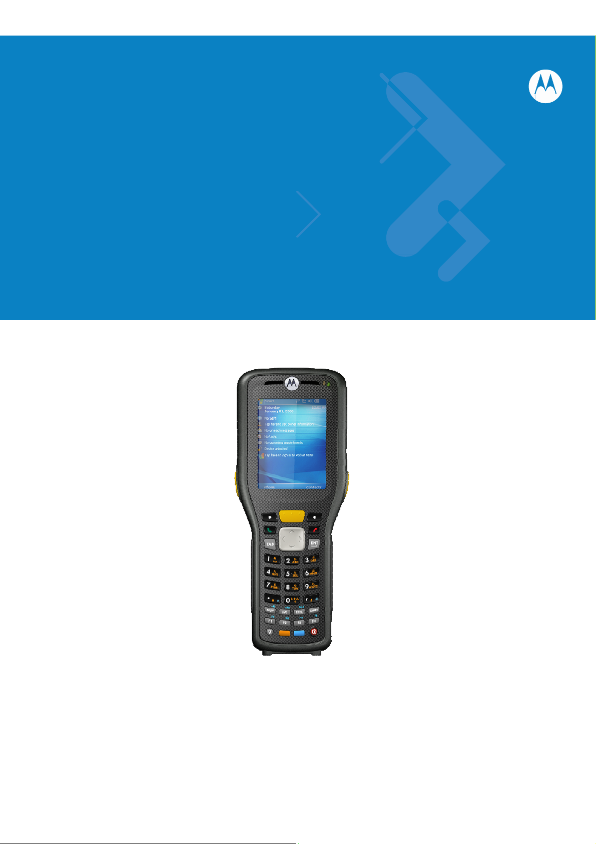
This guide provides information about u sing the FR6070 Enterprise Digital Assistant (EDA) and access ories.
NOTE
Screens and windows pictured in this guide are samples and can differ from actual screens.
Documentation Set
The documentation s et for the FR6070 provides formation for specific user needs, and includ es:
• FR6070 Quick Start Guide - describes ho w to get the FR 6070 up and running.
• FR6070 User Guide - describes how to use the FR607 0
8
Page 9

About This Guide
Configurations
Configuration Radios
FR6070
Software
The second line lists the operating system version and the build number. The last part of the build
number represents the AKU number. For example, Build 18552.0.7.5 indicates that the device is
running AKU version 0.7.5.
This guide covers the following configurations:
WPAN:
Bluetooth
Versi
This guide covers various sof tware configura tions a nd references are made to operating
system or software versions for:
ons
Display Memory
2.8”
VGA
Color
128 MB
RAM/
256 MB
Flash
Data
Capture
1D laser
scanner
Operating
System
Windows
Mobile 6
Professional
Keypads
Alphanumeric
keypad
• Adaptation Kit Update (AKU) version
AKU Ve
T o determine the Adaptation Kit Update (AKU) version:
Tap Start > Settings > System tab > About icon > Version tab.
rsion
9
Page 10

About This Guide
Chapter Descriptions
Topics covered in this guide are as follows:
• Chapter 1, Getting Started provides informatio n on gettin g the FR60 70up and run ning
for the first time.
• Chapter 2, Using the FR6070provides basic instruction s for using the FR6070,
including powering on and resetting the FR6070, and entering and capturing data.
• Chapter 3, Using Bluetooth explains Bluetooth functionality on the FR6070.
• Chapter 4, Accessories describes the available accessories and how to use them
with the FR6070.
• Chapter 5, Maintenance & Troubleshooting includes instructions on cleaning and
storing the FR6070, and provides troubleshooting solutions for potential problems
during FR6070operation.
Notational Conventions
The following conventions are used in this document:
• “Handy” refers to the Motorola FR6070series of hand-held compute rs.
• Italics are used to highlight the following:
• Chapters and sections in this and related documents
• Icons on a screen.
• Bold text is used to highlight the following:
• Dialog box, window , and screen name s
• Drop-down list and list box names
• Check box and radio button names
• Key names on a keypad
• Button names on a screen.
• bullets (•) indicate:
• Action items
• Lists of alternatives
• Lists of required step s that are no t nece ssarily sequential
• Sequential lists (e.g., those that describe step-by-step procedures) appear as
10
Page 11

About This Guide
numbered list s.
Related Documents
• FR6070Quick St art Guide, p/n 72-103079-xx.
• FR6070Windows Mobile 6 Regulatory Guide, p/n 72-103080-xx.
• FR6070Integrator Guide, p/n 72E-103078-xx.
• Microsoft
®
Applications for Mobile 6 User Guide, p/n 72E-108299-xx
• Enterprise Mobility Application Guide, p/n 72E-68901-xx
• Enterprise Mobility Developer Kits (EMDKs), available at: http://support.symbol.com/.
• Latest ActiveSync softw are, available at: http://www.microsoft.com.
For the latest version of this guide and all guides, go to: http://www.symbol.com/manuals.
Service Information
If you have a problem with your equipment, contact Motorola Enterprise Mobility support for
your region. Contact information is available at: http://www.symbol.com/contactsupport
.
When contacting Enterprise Mobility support, please have the following information available:
• Serial number of the unit
• Model number or product name
• Software type and version number
If your problem cannot be solved by Motorola Enterprise Mobility Support, you may need to
return your equipment for servicing and will be given specific directions. Motorola is not
responsible for any damages incurred during shipment if the approved shipping container is
not used. Shipping the units improperly can possibly void the warranty .
If you purchased your Enterprise Mobility business product from a Motorola business partner,
contact that business partner for support.
11
Page 12
Chapter 1 Getting Started
Introduction
This chapter lists the part s and accessories f or the FR6070and explains how to install and charge the batteri es,
replace the strap, and power on the FR6070for the first time.
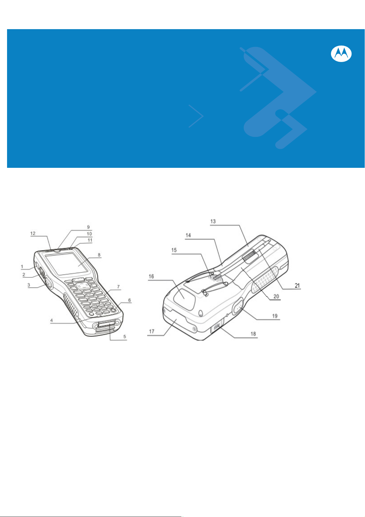
Figure 1-1 FR6070Front View Figure 1-2 FR6070Rear View
1. IrDA Window 2. Headset Jack 13. Battery Door 14. Door Latch
3. Scan Button 4. Microphone (Not available in FR6070)15. Speaker 16. Scan Widnow
5. I/O Connector 6. Power button 17. CF Card Slot 18. SD Card Slot
7. Keypad 8. Touch Screen 19. Scan Button 20. Handstrap
9. Scan/Decode LED 10. Charging LED 21. Stylus
11. Radio Status LED 12. Receiver
11
Page 13

````````````````````````````` Getting Started
Unpacking
Carefully remove all protective material from the FR6070and save the shipping cont ainer for later storage
and shipping.
Verify that you received the following:
• FR6070
• 3600 mAh Lithium-ion battery
• Battery cover/strap assembly
• Tethered stylus
• Protective overlay, installed on display window
• Regulatory Guide
• Quick Start Guide.
Inspect the equipment for damage. If any equipment is missing or damaged, contact the Motorola Enterprise
Mobility Support center immediately. See page xvi for contact information.
12
Page 14
````````````````````````````` Getting Started
Accessories
T ab le 1-1 lists the accessories available for the FR6070.
T
able 1-1 FR6070Accessories
Manufacturing Part Number Description
Cradle
MC70/MC75/FR68/FR6 000 Series RoHS
Compliant Single Slot USB Cradle with Spare
CRD7X00-1000RR
Battery Charging: Must Order power adapter
(KT-14000-148) and US AC Line Cord
(23844-00-00R) separately.
Power Adapter
Power adapter (HP-O2040D43) manufacture
KT-14000-148R
from HIPRO with following
(1)Input 100-240V,50-60Hz,1.5A
(2)Output 12V, 3.33A.
Power adapter (EADP-16BB A)manufacture
from Delta Electronics Ltd. with following
50-14000-249R
(1)Input 100-240V,50-60Hz,0.4A
(2)Output 5.4V, 3A.
.
USB Charging Cable
FR6000 series USB Charging Cable. Requires
25-118708-01R
Miscellaneous
KT-76490-01R
MN2800AAAPCD
MN2800BAAPCD
MN2800AAAPST
MN2800AAAPSP
90-17C28-001R Hands free headset (earbud). This note ONLY
13
power adapter (P/N:50-14000-249R.)
Model:EADP-16BBA, Manufacture: Delta
Electronics Ltd.
Battery adapter (shim for 4 slot charge only;
packet of 5)
FR6070Cradle Adaptor Clip – Adapts
FR6070mobile computer to the crad le. Pac k of
3. (Orders are placed directly FCA Shanghai)
FR6070Cradle Adaptor Clip – Adapts
FR6070mobile computer to the crad le. Pac k of
10. (Orders are placed directly FCA Shanghai)
FR6070spare stylus with teth er. Pack of 3.
(Orders are placed directly FCA Shanghai)
Screen protector for 2.8” QVGA display. Pack of
3. (Orders are placed directly FCA Shanghai)
Page 15
````````````````````````````` Getting Started
A
applies to orders placed directly with Motorola.
FCA Manila, Minimum order: 100 (in Multiples of
100"s there after).
50-11300-050R
Grounded Line Cords
23844-00-00R
50-16000-217R
50-16000-219R
50-16000-220R
50-16000-221R
50-16000-256R
50-16000-257R
50-16000-669R
50-16000-671R
50-16000-672R
50-16000-678R
50-16000-218R
Ungrounded Line Cords
50-16000-182R
50-16000-255R
50-16000-666R
50-16000-664R
50-16000-670R
GSM/GPRS Metal Headset (1 earpiece with
speaker boom)
AC Line Cord, 2.3M, grounded, NEMA 5-15P
plug. Associated Countries: Brazil, United
States
AC Line Cord, 1.8M, grounded, AS 3112 plug.
Associated Country: Australia, China, New
Guinea
AC Line Cord, 1.8M, grounded BS1363 plug.
Associated Countries: Hong Kong, Iraq,
Malaysia, Singapore, United Kingdom
AC Line Cord, 1.8M, grounded CEE 7/7plug.
Associated Countries: Europe, Abu Dabi,
Bolivia, Dubai, Egypt, Iran, Korea, Russia,
Vietnam
AC Line Cord, 1.8M, grounded, USA NEMA
5-15P. Associated Countries: Brazil, United
States
AC Line Cord, 1.8M, grounded,CEE7/7 plug.
Associated Country: Korea
AC Line Cord, 1.8M, grounded, IEC 60320 C13
plug. Associated Country: China
AC Lind Cord, 1.8 M grounded, BS 546 Plug.
Associated Country: India
AC Line Cord, 1.8M grounded, CIE 23-16 plug.
Associated Country: Italy
AC Line Cord, 1.8M grounded, S132 Plug.
Associated Country: Israel
AC Line Cord, 36"L grounded. Associated
Countries: Brazil, United States
AC Line Cord, 1.8M, grounded, NEMA 1-15P
plug. Associated Countries: Japan
AC Line Cord, 1.8M, ungrounded. Associated
Countries: Brazil, United States
AC Line Cord, 1.8M ungrounded, CEE7/16.
Europe, Abu Dabi, Bolivia, Dubai, Egypt, Iran,
Korea, Russia, Vietnam
C Line Cord, 1.8M ungrounded, AS 3112 plug.
Associated Country: Australia
AC Line Cord, 1.8M ungrounded, GB
2099-1-1996 plug. Associated Country: China
AC Lind Cord, 1.8 M ungrounded, BS 1363
Plug. Associated Countries: Bermuda, Hong
Kong, Iraq, Malaysia, Singapore, United
Kingdom
14
Page 16

FR6800
Getting Started
To start using the FR 6070for the first time:
• Install the SIM card (FR6070and FR6070only)
• Install the main battery.
• Charge the FR6070.
• Power on the FR6070.
• Configure the FR6070.
User Guide
Getting Started
15
Page 17
FR6800
User Guide
Installing the Main Battery
NOTE
To install the main battery:
1. Insert the battery, top first, into the battery compartment in the back of the FR6070.
2. Press the battery down into the battery comp artment until the battery release latch snap s into place.
The FR6070ships with a 3600 mAh battery.
NOTE
Position the battery correctly, with the battery charging contacts on top of the charging contacts in the battery
compartment.
Getting Started
Figure 1-4 Inserting the Battery
3. With the battery cover latches open, insert the cover, bottom firs t, then press down on the top of the cover.
4. Close the battery cover latches on either side of the battery cover.
5. Insert the handstrap through the handstrap slot, then tighten and press down to secure.
The FR6070powers up after inserting the battery and replacing th e battery cover.
Charging the Battery
Charging
Before using the FR6070for the first time, charge the main battery u ntil the amber Chargi ng/Battery S t a tus LED
remains lit (see Table 1-2 on page 1-7 for charge status indications). To charge the FR6070, use a cable or a cradle
with the appropriate pow er supply. For info rmation about the accessories availab le for the FR6070, s ee Chapter 6,
Accessories.
The FR6070is equipped with a memory backup battery which automatically c harges from the fully-charg ed main
battery . When using the FR607 0for the first time, the backup battery requires approxi mately 36 hours to fully charge.
This is also true any time the backup b attery is discha rged, which occurs when the main battery is removed for several
hours. The backup battery r etains RAM dat a in memory for at least 15 minute s (at room temperature) when the
FR6070's main battery is removed. When the FR6070 reaches a very low batt ery st ate , the c ombination of main
battery and backup battery retains RAM data in memory for at least 48 hours.
To charge the main battery, use either a charging cable or a cradle. For cable an d cradle setup and charging
procedures refer to the FR6070Integrator Guide.
CAUTION
the Main
Ensure that you follow the guidelines for battery safety described in Ba ttery Sa fety Guidelines on page 7-2.
Battery
and
Memory
Backup Battery
16
Page 18
FR6800
o
User Guide
Getting Started
• Single Slot USB/Serial Cradle
• Vehicle Cradle.
To charge the main battery:
1. Connect the charging accessory to the appropriate power source.
2. Insert the FR6070into a cradle or attach to a cable. The FR6070begins charging. The Charging/Battery Status
LED blinks amber while charging, then turns solid amber when full y charg ed. S ee Table 1-2 for charging
indications.
The 3600 mAh battery fully charges in approxim ately five hours.
T
able 1-2 LED Charge Ind ica to rs
Charging/Battery
Status
LED
Off FR6070is not charging.
FR6070is not inserted correctly in the cradle or connected to a power
source. Charger/cradle is not powered.
Indication
Slow Blinking Amber
(1 blink every 2 seconds)
Solid Green Charging complete.
Fast Blinking Red
(2 blinks/second)
T
able 1-2 LED Charge Indi cato rs (Continued)
Charging/Battery
Single Blink Amber (when device is turned on)
Blink Amber (Battery charger temperature is to
high.)
Status
FR6070is charging.
Note: When the battery is initially inserted in the FR6070, the ambe r LED
flashes once if the battery power is low or the battery is not fully inserted .
Charging error, e.g.:
• Temperature is too low or too high.
• Charging has gone on too long without completion (t ypically ei ght hours).
LED
Battery depleted.
Battery over-temperature condition.
Indication
Charging Spare Batteries
See Chapter 6, Accessories for information on using acce ssories to change spa re batteries.
Charging Temperature
Charge batteries in temperatures from 0°C to 45°C (32°F to 113°F). C harging is intelligently controlled by the
FR6070.
To accomplish this, for small periods of time, the FR6070or accessory alternately enables and disables battery
charging to keep the battery at acceptable temperatures. The FR6070or accessory indicates when charging is
disabled due to abnormal t emperatures via its LED. See Table 1 -2.
Powering On the FR6070
Press the Power button to turn on the FR6 070. If the FR607 0does not power on perform a wa rm boot. See Resetting
17
Page 19
FR6800
User Guide
Getting Started
the FR6070on page 2-14.
When turning the FR6070on for the first time, the splash screen displays for about a minute as the FR6070initializes
its flash file system, t hen the calibration wi ndow appears. Note that these windows also appear u pon cold boot.
Calibrating the Screen
To calibrate the screen so the cursor on the touch screen aligns with the tip of the stylus:
1. Remove the stylus from its holder on the back of the FR6070.
2. Carefully press and briefly hold the tip of stylus on the center of each target that appears on the screen.
3. Repeat as the target moves around the screen, then tap the screen to continue.
Checking Battery Status
To check the charge status of the main battery or backup battery in the FR6070, tap Start > Settings > System tab >
Power icon to display the Power window.
To save battery power, tap the Advanced tab and set the FR6070to turn off after a specified number of minutes.
CF Card Installation
First unscrew the plastic cover, and remove it, insert CF card with the front facing up.
NOTE
When the FR6070powers up after inserting a battery for the first time, the device boots and powers on
automatically.
Micro Secure Digital (microSD) Card
The microSD card slot provides secondary non-volatile storage. The slot is located on the side of the FR6070(see
Figure 1-7). Refer to the document ation provided wi th the card for more information, and follow the manufacturer’s
recommendations for use.
To install the microSD card:
1. Power off the FR6070.
18
CAUTION
Follow proper ESD precautions to avoid damaging the microSD card. Proper ESD precautions
include, but are not limited to, working on an ESD mat and ensuring that the operator is properly
grounded.
Page 20
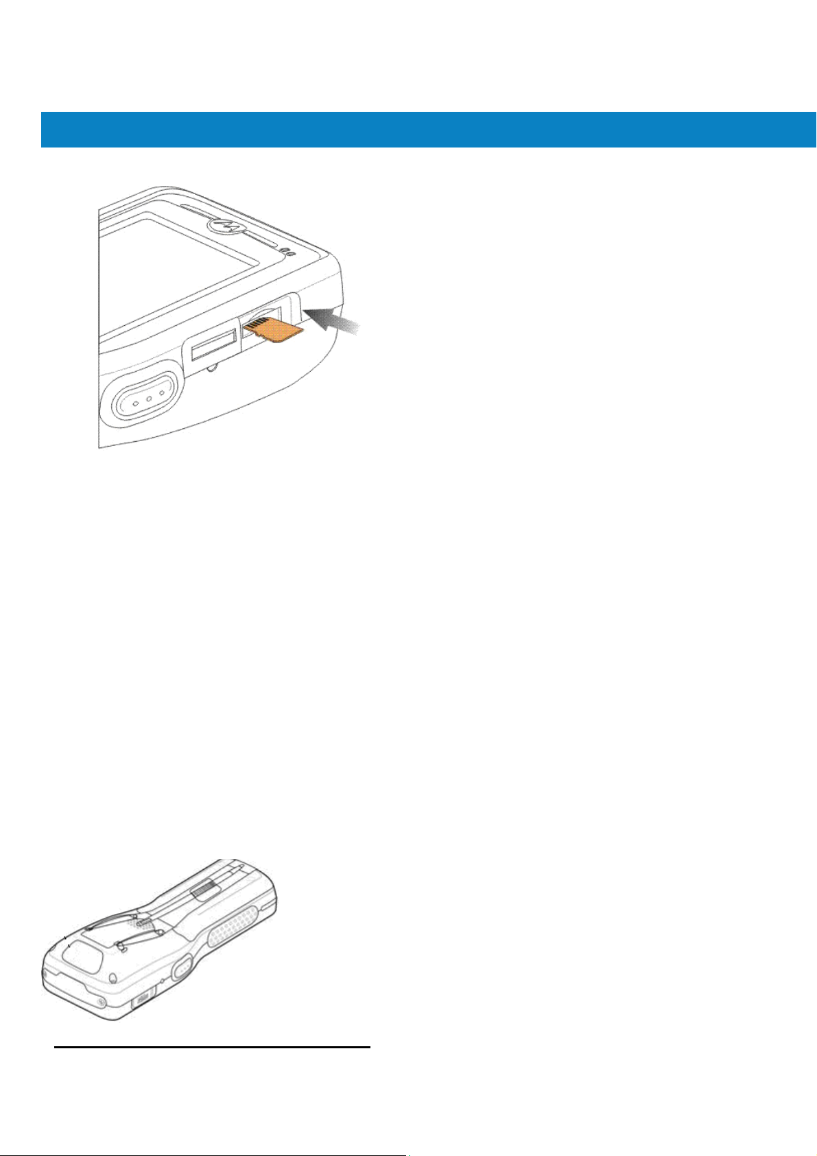
FR6800
2. Remove the memory card cove r on the s ide of the FR6070.
User Guide
Getting Started
Figure 1-6 Card Installation
3. Insert the card with the card contacts facing up and the cut corner on the left, until you feel a click.
4. Replace the memory card cover .
To remove an microSD card:
1. Power off the FR6070.
2. Remove the memory card cover.
3. Carefully press and release the card to eject it.
4. Remove the card from the card slot.11/28
5. Replace the memory card cover.
Adjusting
The FR6070handstrap is attached to the bottom of the battery cover . Adjust the handstrap to increase co mfort
when holding the FR6070for extended periods of time. To adjust the handstrap:
1. Feed the handstrap through the handstr ap slot in ei ther di recti on, to tighten or loosen.
2. Secure the handstrap b y pressing the two si des to gether.
the Handstrap
19
Page 21
FR6800
User Guide
Getting Started
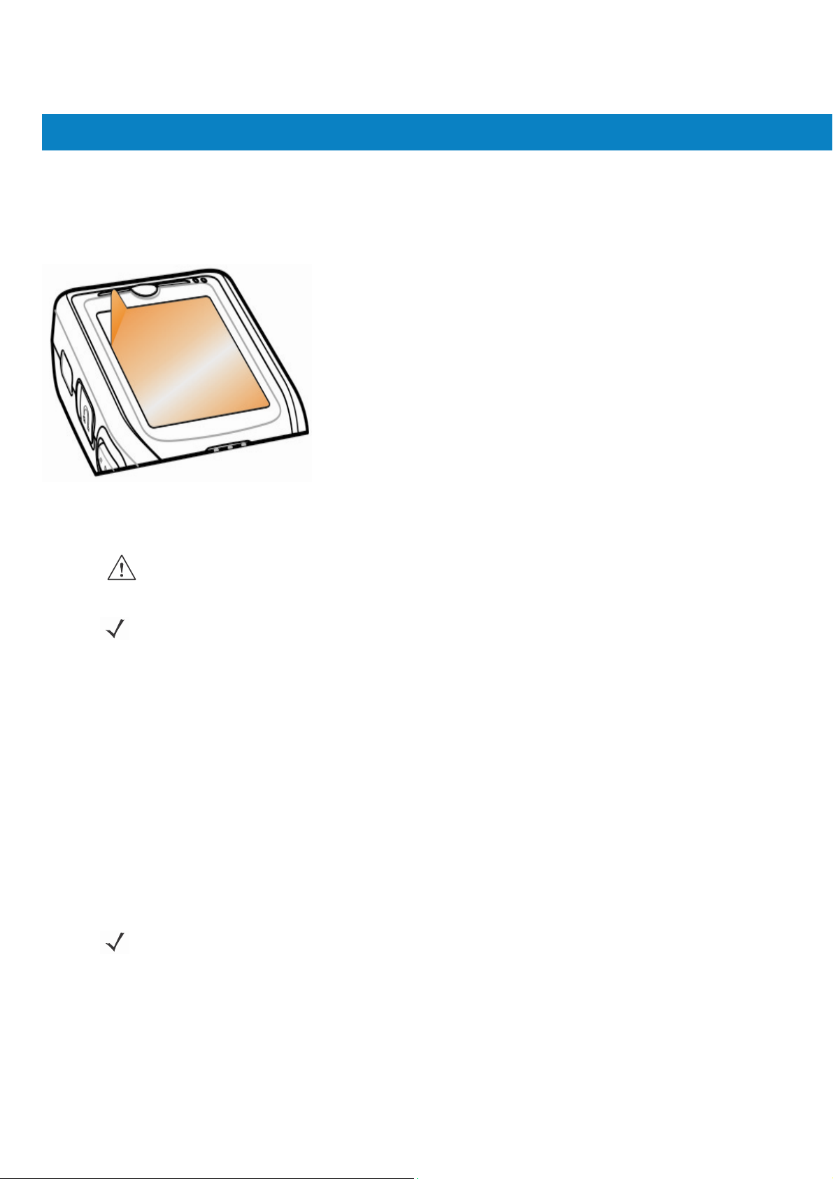
Removing the Screen Protector
A screen protector is applied to the FR6070. Motorola re commends using this to minimize wear and tear. Screen
protectors enhance the usability and durability of touch screen displays.
To remove the screen protector , lif t the corner using a thin plastic card, such as a credit card, then carefully lif t it off
the display.
Figure 1-7 Removing the Screen Protector
CAUTION
NOTE
Do not use a sharp object to remove the protector. Doing so can damage the display.
Not using a screen protector can affect warranty coverage. To purchase replacement protectors, contact
your local account manager or Motorola, Inc. These include screen protector installation instructions. Part
number: KT-93765-01R Screen Protector 3/pk.
Replacing the Main Battery
1. Press the red Power button to suspend the FR6070.
2. Loosen the handstrap.
3. Open the battery cover latches on either side of the battery cover.
4. Lift the top of the battery cover and remove.
5. Press the battery release latch on the bottom of the battery to unlock, and lift the battery out of the well.
6. Insert the replacement batt ery, top firs t, into the battery comp artment in the back of the FR6070.
7. Press the battery dow n into the battery c ompartment until the battery release latc h snap s into place.
NOTE
Position the battery correctly, with the battery charging contacts on top of the charging contacts in the battery
compartment.
8. With the battery c over latc hes open , inse rt the co ver, bottom first, then press dow n on the top of the cover.
9. Close the battery cover latches on either side of the battery cover.
10. Insert the handstrap through the handstrap slot, then tighten and press dow n to secure.
The FR6070powers up after the battery is ins e rted and the battery cover is repla ced.
20
Page 22

FR
6800
G
id
Battery Management
User
u
e
Getting Started
Observe the following battery saving tips:
Changing the Power Settings
To set the FR6070to turn off after a short period of non-u se:
1. Tap Start > Settings > System tab > Power icon > Advanced tab.
2. Select the On battery power: Turn off device if not used for check
NOTE
Leave the FR6070connected to AC power at all times when not in use.
•
• Set the FR6070to turn off after a short period of non-use.
• Set the backlight to turn off after a short period of non-use.
• Turn off all wireless activities when not in use.
• Power off the FR6070when charging to charge at a faster rate.
The FR6070factory default settings for the WWAN and WLAN radios are
set to ON.
box and select a value from the drop-down list.
Changing the Backlight Settings
3. Select ok.
To change the backlight settings in order to conserve more battery power:
1. Tap Start > Settings > System tab > Backlight icon > Power tab.
2. Select the Turn off backlight if device is not used for check box and select a
value from the drop-down list.
3. Select the Brightness tab.
4. Use the slider to set a low value for the backlight.
5. Select ok.
21
Page 23

FR
6800
G
id
User
u
Turning Off the Radios
Windows Mobile 6 devices include Wireless Manager, which provides a simple method of
enabling, disabling, and configuring all the device’s w ireless capabilities in one place.
To open Wireless Manager, tap the Connectivity icon or tap Wireless Manager on the Today
screen.
Figure 1-8 Opening Wireless Manager
Select Wireless Manager.
Connectivity icon
e
Getting Started
Figure 1-9 Wireless Manager Window
To enable or disable a wirel ess conne ction, t a p the specific bu tton.
To enable or disable all wireless connections, t ap the All button. To configure settings for
a connection, tap
22
NOTE
Figure 1-10 Wireless Manager Menu
Wireless connection options vary depending upon configurations.
Menu.
Page 24

Chapter 2 Using the FR6070
Introduction
This chapter explains the buttons, status icons, and controls on the FR6070, and provides basic instructions for
Today Screen
using the FR6070, including powering on and resetting the FR6070, and entering and capturing dat a.
The FR6070factory default radio states are:
• Bluetooth - OFF
• Wireless LAN - ON.
The Today screen dis play s import ant information, s uch as upcoming appointment s and status indicators. Tap a
section on the screen to open the associated program. Alternatively, t ap Start > Today to display the Today
screen.
Open the Start Menu
Change the date and time
Turn on or off radios
Figure 2-1 Today Screen
Adjust volume
Battery Status
Change the date and time, set up the alarm, and more
Soft Keys
Command Bar
26
Page 25

To customize the Today screen, tap Start > Settings > Today icon. Use the Appearance tab to customize th e
background and the Items tab to change the list and order of items that appear on the screen.
Status Icons
The Navigation bar at the top of the screen can contain the st atu s icons listed in Table 2-1.
T
able 2-1 Status Icons
Icon Function
Notification Backup Battery Low.
Connectivity Connection is active.
Using the FR6076
Description
Notification that one or more instant messages were received.
Notification that one or more e-mail/text messages were received.
There are more not ifica tion icons than can be displayed. Tap to display
remaining icons.
Indicates a reminder of an upcoming calendar event.
Connection is not active.
Synchronization is occurring.
Wi-Fi available.
Wi-Fi in use.
Dormant State - no data transmission during a 1x connection. (FR6070and
FR6070)
27
Page 26

T
able 2-1 Status Icons (Continued)
Icon Function
Description
Using the FR6076
Speaker
Battery Main battery is low.
Time and Next
Appointment
Vibrate is on.
Main battery is charging.
Battery power completely depleted.
Main battery level.
Displays c urrent t ime in analog or digit al format.
28
Page 27

The command bar at the bottom of the sc reen can contain the task tray icons listed in Table 2-2.
T
able 2-2 Task Tray Icons
Icon
Programs
T able 2-3 lists the default p rograms in the Start menu.
T
able 2-3 Programs in the Start Menu
Icon
Using the FR6076
Bluetooth Enab led Bluetooth radio is on.
Bluetooth Disabled Bluetooth radio is off.
Bluetooth Connection Bluetooth radio is connected to another Bluetooth device.
ActiveSync Active serial connection between the FR6070and the host computer.
Name
Description
Office Mobile
Use the complete suite of Microsof t® Office applications for your mobile
device.
Excel Mobile - Create new workbooks or view and edit Microsoft
Excel® workbooks.
OneNote Mobile - Create new notes or view existing notes.
®
PowerPoint Mobile - View Microsoft
presentations.
Word Mobile - Create, view, and edit Microsoft
PowerPoint® slides and
®
Word documents.
®
Calendar Keep track of appointments and c reate meeting request s.
Contacts Keep track of friends and colleagues.
Internet Explorer Mobile Browse Web and WAP sites as well as download new program s an d
files from the Internet .
Messaging Send and receive e-mail, MMS, and text messages.
Help See Help topics for the current screen or program.
T ab le 2-4 list s programs th at are listed in the Programs window.
29
Page 28

T
able 2-4 Programs in Program Window
Icon
ActiveSync Synchronize information between the FR6070and a host computer or the
Games Bubble Breaker, Solitaire
Name
Sample AP DataWedge, Notify, and Scanner
Calculator Perform basic arithmetic and calculations, such as addition,
File Explorer Organize and manage files on your device.
Getting Started Display help on how to use some functions
Description
Exchange Server .
subtraction, multiplication, and division.
Using the FR6076
Internet Sharing Connect a notebook computer to the Internet using the FR6070's
data connection.
Messenger Use this mobile ve rsion of Windows Live Messenger.
30
Page 29

T
able 2-4 Programs in Program Window (Continued)
Icon
Notes Create handwritten or typed notes, drawings, and voice recordings.
Name
Description
Using the FR6076
Pictures & Videos View and manage pictures, animated GIFs , and video files.
Search Search contact s, dat a, and other information on your FR6070.
Task Manager Show and stop all the tasks on run
Tasks Keep track of your tasks.
Windows Live Use this mobile version of Windows Live™ to find information on the
web.
Windows Media Player
Mobile
Play back audio and video file s.
31
Page 30

Settings
T ab le 2-5 lists control applications pre inst alled on the FR6070. Tap Start > Settings to open the Settings window.
T
able 2-5 Settings in the Setting Window
Personal T ab
Icon Name
Buttons Assign a program to a button.
Input Set options for each of the input methods.
Description
Using the FR6076
System T ab
Lock Set a password for the FR6070.
Menus Set what programs appear in the St art menu.
Owner Information Enter personal information on the FR6070.
Sounds & Notifications Enable sounds for events , notifications, and mo re, and s et the type of
notification for different events.
Today Customize the appearance and the information to be displayed on the
T oday screen.
About
802.11d Tools
View basic information such as the Windows Mobile® version and type
of processor used on the FR6070.
Enable or disable 802.11d
Backlight Set the display backlight time-out and adjust brightness.
32
Certificates See information about certificates installed on the FR6070.
Clock & Alarms Set the device clock to the date and tim e of your l ocale or to a vis iting
time zone when you’re traveling. Alarms can also be set at specified
days and times of a week.
Page 31

Using the FR6076
Customer Feedback Submit feedback on the Windows Mobile 6 software.
Device information Displays the FR6070’s software and hardware information.
Encryption Allow files on a storage card to be encrypted. Encrypted files are
readable only on your device.
Enroller Allow you to get a Certificate from Certificate servers.
Error Reporting
Managed Programs View installation history.
Memory Check the device memory allocation status and memory card
Power Check battery power and set the time-out for turning off the display to
Regional Settings Set the regional configuratio n to use, including the format for displaying
Enable or disable the device's error reporting function. When this
function is enabled and a program error occurs, technical data about
the state of the program an d your co mputer is logged in a text file and
'
information and stop currently running programs.
conserve battery power .
numbers, currency, date, and time on the FR6070.
Remove Programs Remove programs that you installed on the FR6070.
Screen Change the screen orientation, re-calibrate the screen, and change the
screen text size.
Windows Update Link to Microsoft's web site and update Windows Mobile® on your
device with the latest security patches or fixes. Do not use. Obtain
updates from Motorola.
33
Page 32

T
able 2-5 Settings in the Setting Window (Continued)
Icon Name
Connections Tab
Beam Set the FR6070to receive incoming IrDA beams and bluetooth beam.
Description
Using the FR6076
Bluetooth Search for other Bluetooth devices.
Domain Enroll Enroll in domain.
USB to PC Enables or disables the enhanced network con nectivity.
Wi-Fi Setup wireless network connection and customize settings.
Wireless Manager Enables or disables the FR6070’s wireless radios and customizes
Wi-Fi, Bluetooth
34
Page 33

Adjusting Volume
To adjust the system volume using the Speaker ic on in the navigation bar:
1. Tap the Speaker icon. The Volume dialog box appears.
Figure 2-2 Volume Dialog Box
2. Tap and move the slide bar to adjust the volume.
3. Select the On or Off r adio button to turn th e vo lume on or off.
Y ou can also adjust the system volume using the Sounds & Notifications window , or use the Up/Down button on
the side of the FR6070.
Battery Status Indications
Battery icons appear on the navigation bar indicating the battery power level. W hen the main battery or backup
battery power falls below a predetermine d level, the icon indicates the status and a battery dialog box appears
indicating the status of the main or backup battery.
Using the FR6076
Figure 2-3 Battery Status Dialog Box
The Battery icon alw ays appears in the navigation bar when the Today screen is visible. The icon indicates th e
battery power level. The message displays until the Dismiss button is pressed.
35
Page 34

Using the FR6076
Figure 2-4 Battery Icon on the Title Bar
Also view the battery status using the Power window.
Power Setting
1. Tap Start > Settings > Power icon > Main tab. A power remaining capacity bar appears.
Figure 2-5 Mai n T ab
2. Tick the following options to save the power, and tap ok.
Figure 2-6
36
Advanced Tab
Page 35

Using the FR6076
3. Select Slow charge or Fast charge, and tap ok.
Figure 2-7 USB Charge Tab
Main Battery Temperature Notifications
The temperature notification system implements three levels of notification when the temperature within the battery
exceeds specific temperature thresholds :
• Level 1: T emperat ure W a tch; this level is similar to main battery low warning. It indicates that the battery
temperature has reached the first threshold level. The us er should move to an environment within proper
operating temperature.
• Level 2: T emperature Warning; this level is similar to main bat tery very low warning. It indicates the
battery temperature has reached the second th reshold le vel. The user should stop using the FR6070.
• Level 3: Temperature Error; this level indicates the battery has reached an unusable temperature
threshold and immediately s uspends the FR6070. This level does no t have any graphical notification
associated with it.
Figure 2-8 Main Battery Temperature Watch D ialog Box
37
NOTE
The Temperature Warning dialog box remains visible until you tap Hide.
Figure 2-9 Main Battery Temperature Warning Dialog Box
Page 36

Using the FR6076
LED Indicators
The FR6070has three LED indicators. The Scan/De code LED indicates st atus for bar code scanning. Th e
Charging/Battery S tatus LED indicates battery charging and status. The Radio Status LED indicates W AN radio
1. Scan/Decode LED
LED status Indication
Scan/Decode LED
Solid Green Successful decode/capture
Solid red Laser enabled, scanning in process
Off Not enabled
Charging/Battery Status LED
Slow bl inki ng amber
Solid green
Fast blinking amber
Off
Single blink amber (when p ower button i s
pressed)
Blinking amber (when power button is
pressed)
Radio Status LED
Slow blink green
Slow blink red
Off All radio off.
status. Table 2-6 describes the LED indications.
Figure 2-10 LED Indicators
2. Charging LED
3. Radio Status LED
T
able 2-6 LED Indications
Main battery in FR6070is charging.
Main battery in FR6070is fully charged.
Charging error
Not charging
Battery depleted
Battery over-temperature condition
The radio (BT,WIFI,GPS,RIL) can work
correctly when it is on
Some radio (BT,WIFI,GPS,RIL) can not
work correctly when it is on.
38
Page 37

Resetting the FR6070
There are two reset functions, warm boot and cold boot. A warm boot restarts the FR6070by closing all running
programs. A cold bo ot also restart s the FR6070, and also reset s the clock. Dat a saved in flash memo ry or a
memory card is not lost.
If the FR6070is not functioning properly, perform a warm boot first. If the FR6070still does not respond, perform a
cold boot.
Performing a Warm Boot
Press the reset button to reboot the device.
Performing a Cold Boot
Put the battery into the device, lock the battery cover, and press the power button
Waking the FR6070
The wake-up conditions defin e what actio ns w ake up the mobile computer a f ter it has gone into suspend mode.
The mobile computer can go into suspe nd mode by either pressing the Power button or automa tically by Control
Panel time-out settings. These settings are configurable and the factory default settings are shown in T able 2-7 are
subject to change/update.
T
able 2-7 Wake-up Default Settings
Condition for
Wake-up
Using the FR6076
Power Button Automatic
Ti
me-out
AC power is applied. No Yes
Mobile c omputer is inserted into a cradle. No Yes
Mobile computer is removed from a cradle. No Yes
Mobile computer is connected to a USB device. No Yes
Mobile c omputer is disconnected from a USB device. No Yes
A key is pre ssed. No Yes
The scan triggered is pressed. No Yes
The screen is touched. No No
Audio Jack No No
Audio Btn No No
Bluetooth communication Yes Yes
39
Page 38

Locking the FR6070
Use the Device Lock feature to prevent use of the device. N ote that when lock ed, the FR6070does not respond to
screen or keypad input.
To lock the device, tap the Device unlocked icon. The icon changes to locked.
Figure 2-11 Device Locked/U nlocked Icons
To unlock the device and free it for use, tap Unlock.
Using the FR6076
Figure 2-12 Unlock Device Windo w
Tap Unlock on the Unlock window.
NOTE
You can make emergency calls even when the FR6070is locked. See Making an Emergency Call on page
5-7 for more informat ion.
40
Page 39

Keypads
The FR6070offers one type of modular keyp ad conf iguration: alpha-numeric.
Table 2-8
Key
Alpha-numeric Keypad Input Modes
Numeric
Mode
Orange
(Alpha
Key
Lowercase Mode)
Using the FR6076
Blue+
Key
1 1
2 2 2 @ a B c
3 3 3 # d e f
4 4 4 $ g h i
5 5 5 % j k l
6 6 6 ^ m n o
7 7 7 & p q r s 7 P
8 8 8 * t u v
9 9 9 ( w x y z
0 0 0 )
Note: An
T
able 2-8 Alpha-numeric Keypad Input Modes (Continued)
Key
1
application
SHIFT
+ Key
! Space Space Space Space Space Space Space Space
1st
Press
2nd
Press
3rd
Press
4th
Press
5th
Press
2 A B C
3 D E F
4 G
5 J K L
6 M
8 T U V
9
+
can change
Numeric Mode
+ + +
the key
functions.
Orange
(Alpha
The keypad may
Key
Lowercase Mode)
+
not
6th
Press
7th
Press
8th
Press
9th
Press
H I
N O
Q R S
W
X Y Z
+ + + +
function exactly
Orange + Shift
(Alpha Uppercase
as
described.
Keys
Mode)
Up Up Up Hilight
Blue+
Key
Down Down Down Hilight
Enter Action Action Action Action
Note: An
application
can change
SHIFT
+ Key
Up
Down
the key
1st
Press
Left
Right
functions.
2nd
Press
3rd
Press
The keypad may
4th
Press
not
function exactly
1st
Press
Left
Right
Action
2nd
Press
3rd
Press
as
described.
Alpha-numeric Keypad Configurations
The three types of alpha-numeric keypads produce the 26-charac ter alp habet (A -Z, both low ercase and
uppercase), numbers (0-9 ), and assorted characte rs. The key pad is color-code d to in dicat e w hich mo difier key
to press to produce a particular character or action. The keypad def ault is alphabetic , producing lowercase
letters. See T able 2-8 for key and button descriptions.
41
4th
Press
Page 40

Using the FR6076
Figure 2-13 FR6070Numeric Key p ad
T
able 2-9 Alpha-numeric Keypad Descriptions
Key
Blue Key
Launches applications (shown on the keypad in blue).
Press the Blue key once t o activate t his mode t emporarily , followed by another key. This
displays the followi ng icon at the bottom of the screen, unt il a second key is
pressed:
Press the Blu e key twice to lock this mode. This disp lays the following ic on at the bottom
of the screen:
Press the Blue key a third time to unlock.
Press and hold the Blue key while selecting a sequence o f keys to activate this mode
temporarily. This displays the following icon at the bottom of the screen as long as the key
Orange Key
is pressed:
Accesses the seconda ry layer of characters and actions (shown on the keyp ad in
orange).
Press the Orange key once to act ivate this mod e tempora rily , followed by another ke y .
This displays the following icon at the bottom of the screen, until a second key is
pressed:
Press the Oran ge key twice to lock this mode. This disp lays the fo llowing ico n at the
bottom of the screen:
Press the Orange ke y a third time to unlock.
Press and hold the Orange key while selecting a sequence of keys to activate th is mode
temporarily. This displays the following icon at the bottom of the screen as long as the key
is pressed:
Action
42
Page 41

Using the FR6076
Talk/End
T
able 2-9 Alpha-numeric Keypad Descriptions(continued)
Key
Scroll Up and Left
Not available in FR6070
Not available in FR6070
Action
Moves up one item.
Moves le ft one item when pressed with the Orange key .
Scroll Down and Right Moves down one item.
Moves right one item when pressed with the Orange key .
Soft Keys Acc esses the command or menu a bove it on the sc reen.
Shift
Changes the state of the alpha ch aracters fro m low ercase to uppercase.
• Press the Shift key to activate this mode temporarily, followed by another key .
This displays the following icon at the bottom of the screen, until a second key is
pressed:
z Press and hold the Shift key while selecting a sequence of keys to activate this
mode temporarily. This displays the following icon at the bottom of the screen
as long as the key is pressed:
• Press the Shift key twice to lock this mode. This displays the following icon at
the bottom of the screen:
• Press the Shift key a third time to unlock.
Backlight
Turns the display backlig ht on and off.
Backspace
Produces a backspace.
Enter Executes a selected item or function.
Star Produces an asterisk.
Key
Action
Menu Use this key in conjunction with the Blue key to instantly display the context menu from
any application without tapping the screen. This function is user programmable.
43
Page 42

Using the FR6076
Phonepad
Use this key in conjunction with the Blue key to display the Phonepad application
without tapping the screen. This function is user programmable.
Function Buttons
The FR6070’s buttons perform certain functions.
Figure 2-14
Function Buttons
1. Scan button
2. Power button
• Power: Press the red Power button to turn the FR6070screen on and off. The FR6070is in suspend mode
when the screen is off. For more information, see Powering On the FR6070on page 1-8. Also use the
Power button to reset the FR6070by performing a warm or cold boot. See Resetting the FR6070on page
2-14.
• Scan: Press to scan bar codes. See Data Capture on page 2-29.
44
Page 43

Stylus
Use the FR6070stylus to select items and enter information. The stylus functions as a mouse.
• Tap: Touch the screen once w ith the stylus t o press option butt ons and open menu items .
• T ap and Hold: T ap and hold the stylus on an item to see a list of actions available for that item. On the
pop-up menu that appears, tap the action to perform.
• Drag: Hold the stylus on the screen and drag across the screen to select text. Drag in a list to select
NOTE
CAUTION
Entering Data
When entering data on the keypad, use either the single-hand method or the two-hand method as shown in Figure
2-15.
Figure 2-15 Entering Data on the Keypad
Using theFR6076
multiple items.
Motorola recommends using the spring-loaded tip of the stylus to write on the screen, and the back end of the
stylus to tap the screen. Use your finger to press the Power button and keypad buttons.
To prevent damage to the screen, do not use any device other than the Motorola-provided stylus.
Single-hand Method
Two-hand Method
45
Page 44

Using theFR6076
Data Capture
Linear Scanning
Scanning Considerations
The FR6070offers li near sca nning as data capture.
NOTE
To perform data capture a scanning enabled application must be installed on the FR6070. A sample
scanning
application can be downloaded from the Motorola Support site at http://support.symbol.com.
FR6070with an integrated linear s canner have the fo llowing feature s:
• Reading of a variety of bar code symbologies, including the most popular line ar, postal, and 1-D code
types.
• Intuitive aiming for easy point-and-shoot operation.
Typically, scanning is a simple matter of aim, scan, and decode and a few quick trial efforts master it. However,
consider the following to optimize scanning performance:
• Range
Any scanning device decodes well over a particular working range — minimum and maximum distances from
the bar code. This range varies according to bar code density and scanning device optics.
Scanning within range brings quick and const ant dec odes; scanning too close or too far away prevents
decodes. Move the scanner c loser and further aw ay to find the right working range for the bar codes being
scanned.
• Angle
Scanning angle is important for promoting quick deco des. When las er beams reflect direct ly back into the
scanner from the bar code, this specia l reflec tion can “blind” the sca nner.
To avoid this, scan the bar code so that the beam does n ot bounce di rectly back . But don’t sc an at too s harp
an angle; the scanner needs to collect scattered reflecti ons from the scan to make a succes sful decode.
Practice quickly shows w hat tolerances to work within.
• Hold the FR6070farther away for larger symbols.
• Move the FR6070closer for symbols wi th bars that are close togethe r.
NOTE
1. Ensure that a scan enabled application is loaded on the FR6070.
2. Aim the scan window at the bar code.
Scanning procedures depend on the application and FR6070configuration. An app lication may use different
scanning procedures from the one listed above.
46
Page 45

Using theFR6076
Figure 2-16 Linear Scanning
3. Press the scan button. Ens ure the red scan beam c overs the entire bar code. The Scan/Decode LED light s red
to indicate that scanning is in process, then lights green and a beep sounds, by default, to indicate the bar code
was decoded successfully.
Figure 2-17
Linear Scanner Aiming Pattern
4. Release the scan button.
47
Page 46

Using theFR6076
Using
In a Microsoft Windows Mobile program (except Messaging), and Picture & Videos, you can exchange files using
either infrared or Bluetooth.
IrDA
NOTE
You can also beam files (not folders) from the File Explorer window. Tap and hold
the item you want to
send, then tap
Beam File from the pop-up menu.
First activate the beam function before exchanging files with another IrDA device.
To activate the Beam function:
1. Tap Start > Settings > Connections tab > Beam icon.
2. Tap Receive all incoming beams check box.
Figure 2-18 Beam Window
3. Tap ok.
Infrared Connection
Using infrared, you can enable short-range file exchange between your FR6070and another IrDA device.
Exchanging Files using IR Connection
Ensure that the IrDA function on both the FR6070and the other device are enabled. To send files via IrDA
connection:
1. Switch to the program where you created the item you want to send and locate the item in the list.
2. Align the IrDA port of the FR6070with that of the IrDA device so that they are unobstructed and within a
NOTE
close range.
Do not cover or block the IrDA window.
48
Page 47

Figure 2-19 Align FR6070with IrDA Device
3. T ap and hold the item, then tap Beam [type of item] on the pop-up menu.
4. T ap the device that you want to send the file to.
Using theFR6076
Figure 2-20 Beam Contact Figure 2-21 Receive File
To receive files via IrDA connection:
1. Align the IrDA port of the FR6070with that of the other IrDA device so that they are unobstructed and within a
close range.
2. On the other device, send the file to the FR6070.
3. When the Receiving Data dialog displays, tap Yes.
49
Page 48

Chapter
3 Using Bluetooth
Introduction
Bluetooth-equipped devices can communicate without w ires, using freque ncy-hopping spread spectrum (FHSS)
radio frequency (RF) to transmit and receive data in the 2.4 GHz Industry Scientific and Medical (ISM) band
(802.15.1). Bluetooth wireless technology is specifically designed for short-range (30 feet/10 meters)
communication and low power consumption.
FR6070s with Bluetooth cap abilities can exchange information (e.g. , files, appointments, and tasks) with other
Bluetooth enabled devices such as phones, and other mobile com puters.
Adaptive Frequency Hopping
Adaptive Frequency Hopping (AFH) is a method of avoiding fixed frequency interferers, and can be used with
Bluetooth v oic e. All devices in the pi conet (Bluetooth network) must be AFH-capable in order for AFH to work.
There is no AFH when connecting and discovering devices. Avoid making Bluetooth connections and discoveries
during critical 802.11b communications. AFH for Bluetooth consists of four main sections:
• Channel Classification - A method of detecting an interference on a channel-by-channel basis, or
pre-defined channel mask.
• Link Management - Coordinates and distributes the AFH information to the rest of the Bluetooth network.
• Hop Sequence Modific atio n - Avoids interference by selective l y reducing the number of hopping channels.
• Channel Maintenance - A method for periodically re-evaluating the channels.
When AFH is enabled, the Bluetooth radio “hops around” (instead of through) the 802.11 b high-rate channels. AFH
coexistence allows Motorola mobile computers to operate in any infrastructure.
54
Page 49

The Bluetooth radio in this FR6070operates as a Class 2 device power c lass. The maximum output power is
2.5mW
and the expected range is 32.8 feet (10 meters). A definition of ranges based on power class is difficult to
obtain due to power and device dif ferenc es, and whether one measures op en sp ac e or closed of fice sp ac e.
NOTE
It is not recommended to perform Bluetooth wireless technology inquiry when high rate 802.11b operation
is
required.
Security
The current Bluetooth spe cification defines security at the link level. Application-level security is not specified.
This allows application developers to define security mechanisms tailored to their specific need. Link-level
security occurs between dev ices, not users, while application-level security can be implemented on a per-user
basis. The Bluetooth specification defines security algorithms and procedures needed to authenticate devices,
and if needed, encrypt the data flowing on the link between the devices. D evice authentication is a mandatory
feature of Bluetooth while link encryption is optional.
Pairing of Bluetooth devices is accomplished by creating an initialization key that is used to authenticate the
devices and create a link ke y for them. Entering a common PIN number in the devices being p aire d ge nera tes
the initialization key. The PIN num ber is never se nt over the air. By default, the Bluetooth stack responds w ith
no key when a key is requ e sted (it is up to user to re spon d to the key request event). Auth entication of
Bluetooth devices is based-up on a challenge-response transaction. Bluetooth allow s for a PIN number or
passkey that is used to create other 128-bit keys used for security and encryption. The encryption key is
derived from the link k ey used to authenticate the pairing devices. Also worthy of note is the limited range and
fast frequency hopping of the Bluetooth radios that makes long-distance eavesdropping difficult.
Recommendations are:
• Perform pairing in a secure environment
• Keep PIN codes private and don't store t he PIN codes in the mobile comput er
• Implement application-level security.
Turning the Bluetooth Radio Mode On and Off
Turn of f the Bluetooth radio to save pow er or if entering an are a with radio restrictions (e.g., an airplane). When
the radio is off, other Bluetooth devices cannot see or connect to the FR6070. T urn on the Bluetooth radio to
exchange information with other Bluetooth devices (within range). Communicate only with Bluetooth radios in
close proximity.
Disabling Bluetooth
To disable Bluetooth, tap Bluetooth icon to enter Wireless Manager. Tap Bluetooth icon to change on to off.
The Bluetooth icon c hanges to indicate that Bluetooth is disabled.
NOTE
To achieve the best battery life turn off radios not in use.
55
Page 50

Figure 4-1 Disable Bluetooth
Enabling Bluetooth
To enable Bluetooth, tap Bluetooth icon to enter Wireless Manager. Tap Bluetooth icon to ch ang e off to on.
The Bluetooth icon changes to indicate th at Bl ueto ot h is enabled.
Figure 4-2 Enable Bluetooth
Bond New Device(s)
The FR6070can exc hange in format ion with bonded d e vices.
To find Bluetooth devi ces in the area:
1. Ensure that Bluetooth is enabled on both devices.
2. Ensure that the Bluetooth dev ice to disc over is in discoverable and connectable modes.
3. Ensure that the tw o devi c es are within 30 feet (10 meters) of one a nother.
4. Tap the Bluetooth icon to enter Wireless Manager. Then tap Menu.
56
Page 51

Figure 4-3 Enter Bluetooth Window
5. Tap Menu to enter Settings window. Then tap Add new device to search for Bluetooth Devices.
Figure 4-4
Add new device Window
After the device appears, tap it and enter a passcode to establish a secure connection with it. Meanwhile
6.
enter the passcode on the target device.
Figure 4-5 Discover Devices Dialog Box
File Transfer Services
To transfer files between the FR6070and another Bluetooth enabled device, please ensure the FR6070is
discoverable and connectable.
57
NOTE
Some devices might not require a PIN. This depends upon the device’s authentication.
Page 52

1. Choose one file as below, tap Menu > Beam picture Menu.
Figure 4-6 Select file
2. Then choose the destination device, and wait till Done is showed.
Figure 4-7 Transfer file Window
Bluetooth Settings
Use the Bluetooth Settings window to configure the operation of the application. Tap Menu >
Device Info Tab
Mode Tab
Settings. The Bluetooth Settings window appears.
Use the Device Info tab to add and bond new devices. Please refer to Bond new device(s).
Use the Mode tab to configure th e FR6070’ s Bluetooth connection modes.
58
Page 53

Figure 4-8 BTExplorer Settings - Device Info Tab
1. Before bonding a new device, make sure to turn on Bluetooth.
2. If you want other devices to find your FR6070, please tick “Make this device visible to other devices”.
COM Ports Tab
1. Tap New Outgoing Port.
Use the COM Ports tab set specific outgoing ports for bonded devices.
Figure 4-9 Add COM P o r t s
2. Select the device you want to add. Then tap Next.
Figure 4-10 Select device
3. Select a port from drop-down list. Then tap Finish.
59
Page 54

Figure 4-11 Select a Port for device
60
Page 55

Chapter 4 Accessories
Introduction
FR6070accessories, listed below, provide a variety of product support
capabilities.
• Single Slot USB/Serial Cradle - Charges th e FR6070main battery and a sp are battery. Synchronizes the
FR6070with a host computer through a USB connection.
• Four Slot Battery Charger - Charges spare st andard a nd high capacity batteries.
• Auto Charge Cable - Plugs into a vehicle cigarette lighter to charge the FR6070while on the road.
• Charge Only Cable - Provides power to the FR6070.
• USB Charging Cable - Provides power to the FR6070and USB communication with a host computer.
• Headset - Used in noisy environments.
Single Slot USB/Serial Cradle
This section describes how to use a Single Slot USB/Serial cradle with the FR6070. For USB communication
Charging the FR6070Battery
setup procedures refer to the FR6070Integrator Guide.
The Single Slot USB/Serial Crad le:
• Provides 5.4 VDC power for operating the FR6070.
• Synchronizes information between the FR6070and a host computer . Refer to the FR6070Integrator
Guide for information on setting up a partnership betw een the FR6070and a host computer.
• Charges the FR6070’s battery.
• Charges a spare battery .
Connect the cradle to power. Insert the FR60 70into the slot to begin charging.
Note : Please put the adapto r clip into the cradle before charging.
*Charging LED
Accessories
61
Page 56

Accessories
Slow Blinking Amber=Charging
Solid Green=Fully Charged
Fast Blinking Red=Charging Error
*It is recommended that this product be charged for 24 hours before the first use to ensure that the internal
battery is fully charged.
Figure 6-1 FR6070Battery Charging
Charging the Spare Battery
Figure 6-2 Spare Battery Charging
62
Spare Battery
Page 57

Accessories
Battery Charging Indicators
The Single Slot USB/Serial Cradle charges the FR6070’s main battery and a spare battery sim ult aneously.
The FR6070’s charge LED indic ates the st atus of the battery charging in the FR6070. See Table 1-2 on page 1-7
for charging s tatus indications.
The spare battery chargin g LE D on the cradle indicat es the st atus of the sp are batte ry c hargin g in the c radle. See
T ab le 6-1 for charging status indications.
The 3600 mAh battery fully charges in less than five hours .
Charging Temperature
Charge batteries in temperatures from 0°C to 45°C (32°F to 113°F). Charging is intelligently controlled by the
FR6070
.
To accomplish this, for small periods of time, the FR6070or accessory alternately enables and disables
battery charging to keep the battery at acceptable temperatures. The FR6070or accessory indicates when
charging is disabled due to abnormal temperatures via it s LED. See Table 1-2 o n page 1-7 and Table 6-1.
T
able 6-1 Spare Battery LED Charging Indicators
Spare Battery LED
(on cradle)
Off Battery is not charging; battery is not inserted correctly in the cradle;
cradle is not powered
Indication
Slow Blinking Amber Sp are battery is charging.
Solid Amber Charging complete.
63
Page 58

Headset
Use the headset to communicate via Voice-Over-IP (VOIP) or for audio playback and telephony applications.
To connect the headset, remove the plug from the headset jack at the top of the FR6070and insert the headset
connector. Contact a Motorola representative for compatible headsets.
For best performance, Mo torola rec ommends a 2.5mm jack headset, p/n 50-11300-050R.
Figure 6-5 Headset Connection
Cables
This section describes how to set up and use the cables. The cables are available w ith a variety of
connection capabilities.
The following communication/charge cables are available:
• USB Client Charge cable (standard-A connector and a barrel receptacle for power)
• Auto charge cable
• Charge only cable.
The following printer cabl es are available directly from Motorol a:
• O’Neil Printer cable
• Zebra Printer cable.
Accessories
Figure 6-6 Cables
64
Communication/charge cables:
• Provide the FR6070with operating and charging pow er w hen used w ith the Motorola approved power
Page 59

Accessories
supply.
• Synchronize information between the FR6070and a host compu ter. With cust omiz ed or third party
software, it can also synchronize the FR6070with corporate dat abases.
• Provide USB connection through the USB pass-through port for communication with a USB device,
Dedicated printer cables provide communication with a printer.
Battery Charging and Operating Power
The communication/charge cables can charge the FR6070battery and supply operating
power. To charge the FR6070battery:
1. Connect the communication/charge cable power input connector to the Motorola approved power source.
2. Slide the bottom of the FR6070into the connector end of the communication/charge cable and gently
3. When charging is complete, remove the cable by gently pulling the FR6070and the cable
such as a host computer. For communication setup procedures, refer to the FR6070Integrator Guide.
press in until it latches into the FR6070. The FR6070amber Cha rge LED indicates the FR6070batter y
charging status. The 3600 mAh standard batte ry charges in less than five hours. See Table 1-2 on page
1-7 for charging status indications.
apart.
LED Charge Indications
The amber Charge LED on the FR6070indicates battery charging status. See Table 1-2 on page 1-7 for charging
status indications.
Charging Temperature
Charge batteries in temperatures from 0°C to 45°C (32°F to 113°F). Charging is intelligently controlled by the
FR600
To accomplish this, for small periods of time, the FR6070or accessory alternately enables and disables battery
charging to keep th e battery at accep ta ble tempera tures . The FR6070o r accessory indicates when ch arging is
disabled due to abnormal temperatures via it s LED. See Table 1-2 on page 1-7.4
65
Page 60

Chapter 5 Maintenance&Troubleshooting
Introduction
This chapter includes instructions on cleaning and storing the FR6070, and provides troubleshooting solutions
Maintaining the FR6070
for potential problems during FR6070operation.
For trouble-free service, observe the following tips when using the FR6070:
• Do not scratch t he screen of the FR60 70. Whe n w orking w ith the FR6070, use the supplied stylus or
plastic-tipped pens intended for use with a touch-sensitive screen. Never use an actual pen or pencil or other
sharp object on t he surface of the FR6070screen.
Motorola recommends using a screen protector, p/n KT -67525-01R.
• The touch-sensitive screen of the FR6070is glass. Do not to drop the FR6070or subject it to strong impact.
• Protect the FR6070from temperature extremes. Do not leave it on the dashboard of a car on a hot day,
and keep it away from heat sources.
• Do not store or use the FR6070in any location that is dusty, damp, or wet.
• Use a soft lens cloth to clean the FR6070. If the surface of the FR6070screen becomes soiled, clean it with a
soft cloth moistened with a diluted window-cleaning solution.
• Periodically replace the rechargeable battery to ensure maximum batte ry life a nd product pe rformance.
Battery life depends o n individual usag e patte rns.
66
Page 61

&
Maintenance
Troubleshooting
• A screen protector is applied to the FR6070. Motorola reco mmends using this to minimize wear and tear.
Screen protectors enhance the usability and durability of touch screen displays. Benefits include:
• Protection from scratches and gouges
• Durable writing and touch surface with tactile feel
• Abrasion and chemical resistance
• Glare reduction
• Keeping the device’s screen looking new
• Quick and easy installation.
Battery Safety Guidelines
• The area in which the units are charged should be clear of debris and combustible materials or chemicals.
Particular care should be taken where the device is charged in a non commercial environ m en t.
• Follow battery usage, storage, and charging guidelines found in the user's guide.
• Improper batt ery use may res ult in a fire, explo sio n, o r othe r h aza rd.
• To charge the mobile device battery, the battery and charger temperat ures must be between +32 ºF and
+113 ºF (0 ºC and +45 ºC)
• Do not use incompatible batteries and chargers. Use of an incompatible battery or charger may present a
risk of fire, explosion, leakage, or other hazard. If you have any question s about the compatibility of a battery
or a charger, contact Motorola Enterprise Mobility support.
• For devices that utilize a USB port as a charging so urce, t he device s hall only be con nected to produc ts that
bear the USB-IF logo or have completed the USB-IF compliance pr ogram.
• To enable authentication of an approved battery, as required by IEEE1725 clause 10.2.1, all batteries will
carry a Motor ola hologram. Do not fit any batt ery without checking it has the Motor ola authentication
hologram.
• Do not disassemble or open, crush, bend or deform, puncture, or shred.
• Severe impact from dr opping any battery-operat ed device on a hard surface could c ause th e battery
to overheat.
• Do not short circuit a battery or allow metallic or conductive object s to cont act the battery terminals.
• Do not modify or remanufacture, attempt to insert foreign objects into the battery, immerse or expose to
water or other liquids, o r ex pose to fire, explosion, or ot her hazard.
• Do not leave or store the equipment in or near areas that might get very hot, such as in a parked vehicle or
near a radiator or other heat source. Do not place battery into a microwave oven or dryer.
• Battery usage by children should be supervised.
• Please follow local regulati ons to promptly d ispose of used re-chargeable b atteries.
• Do not dispose of batteries in fire.
• Seek medical advice immediately if a battery has been sw allowed.
• In the event of a battery leak, do not allow the liquid to come in contact with the skin or eyes. If contact has
been made, wash the a f fected area w ith large a mount s of water and se ek medical a dvice.
• If you suspect damage to your equipment or battery, cont act Motorola Enterprise Mobility support to
arrange for inspection.
67
Page 62

&
Maintenance
Troubleshooting
Cleaning
Materials Required
Cleaning the FR6070
Housing
Using the alcohol wipes, wipe the housing including k eys and in-betw een keys.
Display
The display can be wiped down with the alcohol w ipes, but care should be ta ken not to allow any pooling of liquid
around the edges of the display. Immediately dri ed the display with a sof t, non-abrasiv e cloth to prevent streaking.
Scanner Exit Window
Wipe the scanner exit window periodically with a lens tissue or other material suitable for cleaning optical material
such as eyeglasses .
Connector
1. Remove the main battery from mobile computer. See Replacing the Main Battery on p age 1-11.
2. Close battery door.
3. Dip the cotton portion of the cotton ti pped applicator in isopropyl al cohol.
4. Rub the cotton portion of the cotton tipped applicator back -and-forth across the connec tor on th e bott om of the
5. Repeat at least three times.
6. Use the cotton tipped applicator dipped in alcohol to remove any grease and dirt near the connector area.
7. Use a dry cotton tipped applicator and repeat ste ps 4 through 6.
CAUTION
WARNING
Always wear eye protection.
Read warning label on compressed air and alcohol product before using.
If you have to use any other solution for medical reasons please contact Motorola for more information.
!
Avoid exposing this product to contact with hot oil or other flammable liquids. If such exposure
occurs, unplug the device and clean the product immediately in accordance with these guidelines.
• Alcohol wipes
• Lens tissue
• Cotton tipped applicators
• Isopropyl alcohol
• Can of compressed air with a tube.
FR6070. Do not leave any cotton residue on the conn ector.
68
Page 63

&
Maintenance
Troubleshooting
8. Spray compr essed ai r on the connector area by pointing the tub e/nozz le about ½ inch away from the su rfac e.
CAUTION: Do n ot point nozz le at yours elf and oth ers, ensure the no zzle or tube is away from your face.
9. Inspect the area for any grease or dirt, repeat if required.
Cleaning Cradle Connectors
To clean the connectors on a cradle:
1. Remove the DC power cable from the cradle.
2. Dip the cotton portion of the cotton ti pped applicator in isopropyl al cohol.
3. Rub the cotton portion of the cotton tipped applicator along the pins of the connector. Slowly move the
applicator back-and-forth from one side of the connector to the othe r. Do not let any cotton residue on the
connector.
4. All sides of the connector sho uld also be rubbed w ith the cotton tipped ap plicator.
5. Spray compr essed air in the connector area by pointing th e tube/nozzle about ½ inch away from the s urfac e.
CAUTION: do not poin t noz zle at yo urself and others, ensure the no zzle or tube is pointed away from your
face.
6. Ensure that there is no lint lef t by the cotton tipped applicator, remove lint if found.
7. If grease and other dirt can be found on other areas of the cradle, use lint free cloth and alcoh ol to remove.
8. Allow at least 10 to 30 minutes (depending on ambient temperature and humidity) for the alcohol to air dry
before applying power to cradle.
If the temperature is low and humidity is high, longer drying time is required. W arm temperature and dry
humidity requires less drying time.
Cleaning Frequency
The cleaning frequency is up to the customer’s discretion due t o the varied e nvironments in which the mobile
devices are used. They may be cleaned as frequently as required. However when used in dirty e nvironment s it
may be advisable to periodically clean the scanner exit window to ensure optimum scanning performance.
69
Page 64

&
Maintenance
Troubleshooting
Troubleshooting
FR6070
T
able 7-1 Troubleshooting the FR6070
Problem
Cause
Solution
FR6070does not
turn on.
Rechargeable
lithium-ion battery did
not charge.
Cannot see characters
on display .
During data
communication,
data transmitted, o r
transmitted data was
incomplete.
no
Lithium-ion battery
not charged.
Lithium-ion battery
not installed
properly.
System crash. Perform a warm boot. If the FR6070still does not turn on, perform
Battery failed. Replace battery . If the FR6070still does not operate, perform a
FR6070removed
from cradle whi le
battery was
charging.
Extreme battery
temperature.
FR6070not
powered on.
FR6070removed
from cradle or
disconnected from
host computer
during
communication.
Charge or replace the lithium-ion battery in the FR6070.
Install the battery properly . See Installing the Main Battery on page
1-6.
a cold boot. See Resetting the FR6070on page 2-14.
warm boot, then a cold boot. See Resetting the FR6070on page
Insert FR6070in cradle. The 3600 mAh battery fully charges in
less than six hours.
Battery does not charge if ambient temperature is below 0°C (32°F)
or above 45 °C (113°F).
Press the Power button.
Replace the FR6070in the cradle, or reatt ach the
communication
cable and re-transmit.
Incorrect cable
configuration.
Communication
software was
incorrectly installed
or configured.
No sound. V olume setting is
low or turned of f.
70
See the system administrator.
Perform setup. Refer to the FR6070Integrator Guide for details.
Adjust the volume. See Adjusting Volume on page 2-10.
Page 65

&
T
able 7-1 Troubleshooting the FR6070(Continued)
Problem
FR6070shuts off. FR6070is inactive. The FR6070turns off after a period of inactivity . If the FR6070is
Cause
Battery is depleted. Replace the battery.
running on battery power, set this period from 1 to 5 minutes, in
one-minute intervals. If the FR6070is running on external power,
set this period to 1, 2, 5, 10, 15, or 30 minutes.
Check the Power window by selecting
and tapping the
the setting for a longer delay before the automatic shutoff feature
activates.
Solution
Power icon. Select the Advanced tab and change
Maintenance
Troubleshooting
Start > Settings > System tab
T apping the window
buttons or icons does
not activate the
corresponding feature.
A message appears
stating that the
FR6070memory is
full.
FR6070keeps
powering down to
protect memory
contents.
Battery is not
inserted properly .
Screen is not
calibrated correctly.
The system is not
responding.
T oo many fi les
stored on the
FR6070.
T oo many
applications
installed on the
FR6070.
The FR6070’ s
battery is low.
The internal
Bluetooth radio is
powered on for a
long time.
Insert the battery properly . See Installing the Main Battery on page
1-6.
Re-calibrate the screen. See Calibrating the Screen on page 1-8.
Warm boot the system. See Resetting the FR6070on page 2-14.
Delete unused memos and records. If necessary, save these
records on the host computer (or use an SD card for additional
memory).
Remove user-installed applications on the FR6070to recover
memory. Select
Programs
Recharge the battery.
Start > Settings > System tab and tap the Remove
icon. Select the unused program and tap Remove.
Because this mode requires battery power, power it off when not
needed.
71
Page 66

&
T
able 7-1 Troubleshooting the FR6070(Continued)
Problem
Cause
Solution
Maintenance
Troubleshooting
The FR6070does
not accept scan
input.
Scanning
application is not
loaded.
Unreadable bar
code.
Distance between
exit window and bar
code is incorrect.
FR6070is not
programmed for the
bar code.
FR6070is not
programmed to
generate a beep.
Battery is low. If the scanner stops e mitting a laser beam upon a trigger press,
Bluetooth Connection
T
able 7-2 Troubleshooting Bl uetooth Connection
Problem
Cause
Load a scanning application on the FR6070. See the
system administrator.
Ensure the symbol is not defaced.
Place the FR6070within proper scanning range.
Program the FR6070to accept the type of bar code bein g scanned.
If the FR6070does not beep on a good decode, set the application
to generate a beep on good decode.
check the battery level. When the battery is low , the scanne r shuts
off before the FR6070low battery condition no tification. Note: If the
scanner is still not reading symbols, contact the distributor or
Motorola.
Solution
FR6070cannot find
any Bluetooth
devices nearby.
72
T oo far from other
Bluetooth devices.
The Bluetooth
device(s) nearby are
not turned on.
The Bluetooth
device(s) are not in
discoverable mode.
Move closer to the other Bluetooth devic e(s), within a range of 10
meters.
Turn on the Bluetooth device(s).
Set the Bluetooth device(s) to discoverable mode. If needed, refer to
the device’s user documentation for help.
Page 67

&
Maintenance
Troubleshooting
Single Slot USB/Serial Cradle
T
able 7-3 Troubleshooting the Single Slot USB/Serial Cradle
Symptom
Possible
Cause
Action
LEDs do not light
when FR6070or
spare battery is
inserted.
Cradle is not
receiving power.
FR6070is not
seated firmly in the
Sp are battery is not
seated firmly in the
cradle.
Ensure the power cable is connected securely to both the cradle
and to AC power.
Remove and re-insert the FR6070into the cradle, ensuring it is
firmly seated.
Remove and re-insert the spare battery into the charging slot,
ensuring it is firmly seated.
73
Page 68

&
able 7-3 Troubleshooting the Single Slot USB/Serial Cradle (Continued)
T
Symptom
Possible
Cause
Maintenance
Action
Troubleshooting
FR6070battery is
not charging.
Sp are battery is not
charging.
FR6070was
removed from
cradle or
cradle was
unplugged from AC
power too soon.
Battery is faulty . Verify that other batteries charge properly . If so, replace the faulty
The FR6070i s
not fully seated in
the cradle.
Ambient
temperature of the
cradle is too warm.
Extreme battery
temperature.
Battery not fully
seated in charging
slot.
Battery inserted
incorrectly.
Ensure cradle is receiving power. Ensure FR6070is seated
correctly . Confirm main battery is charging under
System > Power. The 3600 mAh battery fully charges in less than
six hours.
Start > Settings >
battery.
Remove and re-insert the FR6070into the cradle, ensuring it is
firmly seated.
Move the cradle to an area where the ambient temperature is
between 0°C (32°F) and 35°C (95°F).
Battery does not charge if ambient temperature is below 0°C (32°F)
or above 45°C (113°F).
Remove and re-insert the spa re battery in the cradle, ensuring it is
firmly seated.
Re-insert the battery so the charging contacts on the battery align
with the contacts on the cradle.
During data
communication,
data transmit s, or
transmitted data was
incomplete.
no
Battery is faulty . Verify that other batteries charge properly . If so, replace the faulty
Ambient
temperature of the
cradle is too warm.
FR6070removed
from cradle during
communications.
Incorrect cable
configuration.
Communication
software is not
installed or
configured properly .
battery.
Move the cradle to an area where the ambient temperature is
between 0°C (32°F) and 35°C (95°F).
Replace FR6070in cradle and retransmit.
See the system administr ator.
Perform setup as described in the FR6070Integrator Guide.
74
 Loading...