

Page 1
ES3000 Ethernet Switch
User Guide
Page 2

Page 3

ES3000
Ethernet Switch
User Guide
72E-68446-01
Revision A
May 2004
Page 4

© 2004 by Symbol Technologies, Inc. All rights reserved.
No part of this publication may be reproduced or used in any form, or by any electrical or mechanical means,
without permission in writing from Symbol. This includes electronic or mechanical means, such as
photocopying, recording, or information storage and retrieval systems. The material in this manual is subject to
change without notice.
The software is provided strictly on an “as is” basis. All software, including firmware, furnished to the user is
on a licensed basis. Symbol grants to the user a non-transferable and non-exclusive license to use each
software or firmware program delivered hereunder (licensed program). Except as noted below, such license may
not be assigned, sublicensed, or otherwise transferred by the user without prior written consent of Symbol. No
right to copy a licensed program in whole or in part is granted, except as permitted under copyright law. The
user shall not modify, merge, or incorporate any form or portion of a licensed program with other program
material, create a derivative work from a licensed program, or use a licensed program in a network without
written permission from Symbol. The user agrees to maintain Symbol’s copyright notice on the licensed
programs delivered hereunder, and to include the same on any authorized copies it makes, in whole or in part.
The user agrees not to decompile, disassemble, decode, or reverse engineer any licensed program delivered to
the user or any portion thereof.
Symbol reserves the right to make changes to any software or product to improve reliability, function, or design.
Symbol does not assume any product liability arising out of, or in connection with, the application or use of any
product, circuit, or application described herein.
No license is granted, either expressly or by implication, estoppel, or otherwise under any Symbol Technologies,
Inc., intellectual property rights. An implied license only exists for equipment, circuits, and subsystems
contained in Symbol products.
Symbol, Spectrum One, and Spectrum24 are registered trademarks of Symbol Technologies, Inc. Other product
names mentioned in this manual may be trademarks or registered trademarks of their respective companies
and are hereby acknowledged.
Symbol Technologies, Inc.
One Symbol Plaza
Holtsville, New York 11742-1300
http://www.symbol.com
Page 5

Contents
About This Guide
Introduction . . . . . . . . . . . . . . . . . . . . . . . . . . . . . . . . . . . . . . . . . . . . . . . . . . . . . . . . vii
Notational Conventions . . . . . . . . . . . . . . . . . . . . . . . . . . . . . . . . . . . . . . . . . . . . . . . vii
Service Information. . . . . . . . . . . . . . . . . . . . . . . . . . . . . . . . . . . . . . . . . . . . . . . . . . .viii
Chapter 1. Switch Management Overview
About the ES3000 Ethernet Switch . . . . . . . . . . . . . . . . . . . . . . . . . . . . . . . . . . . . . 1-1
Management Access Overview . . . . . . . . . . . . . . . . . . . . . . . . . . . . . . . . . . . . . . . . 1-2
SNMP Access . . . . . . . . . . . . . . . . . . . . . . . . . . . . . . . . . . . . . . . . . . . . . . . . . . . . . . 1-2
Protocols . . . . . . . . . . . . . . . . . . . . . . . . . . . . . . . . . . . . . . . . . . . . . . . . . . . . . . . . . . 1-2
Virtual Terminal Protocols . . . . . . . . . . . . . . . . . . . . . . . . . . . . . . . . . . . . . . . . 1-2
SNMP Protocol . . . . . . . . . . . . . . . . . . . . . . . . . . . . . . . . . . . . . . . . . . . . . . . . . 1-3
Default Installation . . . . . . . . . . . . . . . . . . . . . . . . . . . . . . . . . . . . . . . . . . . . . . . . . . 1-3
Preparing for Site Installation. . . . . . . . . . . . . . . . . . . . . . . . . . . . . . . . . . . . . . 1-3
Package Contents . . . . . . . . . . . . . . . . . . . . . . . . . . . . . . . . . . . . . . . . . . . . . . . 1-4
Page 6

iv
ES3000 User Guide
Supplying Power. . . . . . . . . . . . . . . . . . . . . . . . . . . . . . . . . . . . . . . . . . . . . . . . 1-5
Establishing a RS-232 Serial Connection to the Ethernet Switch . . . . . . . . . . 1-5
Administration of the ES3000 Ethernet Switch . . . . . . . . . . . . . . . . . . . . . . . . . . . . 1-6
Installing a SFP Fiber Transceiver. . . . . . . . . . . . . . . . . . . . . . . . . . . . . . . . . . . . . . . 1-9
Chapter 2. Firmware Upgrades
Chapter 3. Administration Console Access
Direct Access Management Method . . . . . . . . . . . . . . . . . . . . . . . . . . . . . . . . . . . . 3-1
User Interface . . . . . . . . . . . . . . . . . . . . . . . . . . . . . . . . . . . . . . . . . . . . . . . . . . . . . . 3-5
Saving Configuration Changes . . . . . . . . . . . . . . . . . . . . . . . . . . . . . . . . . . . . . . . . . 3-5
Main Menu Options . . . . . . . . . . . . . . . . . . . . . . . . . . . . . . . . . . . . . . . . . . . . . . . . . 3-6
General Information . . . . . . . . . . . . . . . . . . . . . . . . . . . . . . . . . . . . . . . . . . . . . . . . . 3-8
Main Menu->System Administration->System Configuration. . . . . . . . . . . . . 3-9
Main Menu->System Admin.->Access Configuration . . . . . . . . . . . . . . . . . . 3-10
Main Menu->Access->System IP Configuration . . . . . . . . . . . . . . . . . . . . . . 3-11
Main Menu->Access->Management Access. . . . . . . . . . . . . . . . . . . . . . . . . 3-12
Main Menu->System Admin->SNMP Configuration Menu . . . . . . . . . . . . . . 3-14
Main Menu->SNMP Config.->System Information . . . . . . . . . . . . . . . . . . . . 3-16
Main Menu->SNMP Config.->Authorized Managers. . . . . . . . . . . . . . . . . . . 3-17
Main Menu->SNMP Config.->Trap Receiver Configuration . . . . . . . . . . . . . 3-18
Main Menu->SNMP Config. ->Trap Selection . . . . . . . . . . . . . . . . . . . . . . . . 3-19
Port Link Down Trap . . . . . . . . . . . . . . . . . . . . . . . . . . . . . . . . . . . . . . . . 3-19
Link Down Trap. . . . . . . . . . . . . . . . . . . . . . . . . . . . . . . . . . . . . . . . . . . . 3-19
Main Menu->System Admin. ->Tools Menu . . . . . . . . . . . . . . . . . . . . . . . . . 3-21
Main Menu->System Admin.->Tools->Software Upgrade . . . . . . . . . . . . . . 3-22
Main Menu->System Admin.->Tools->System Reboot . . . . . . . . . . . . . . . . . 3-23
Main Menu->System Admin.->Tools->Save Config. . . . . . . . . . . . . . . . . . . . 3-24
Main Menu->System Admin. ->Tools ->Upload/Download Config. . . . . . . . 3-25
Main Menu->System Admin.->Tools->SNTP Config.. . . . . . . . . . . . . . . . . . . 3-26
Main Menu->System Admin.->Tools->System Log . . . . . . . . . . . . . . . . . . . . 3-27
Main Menu->Port Configuration Menu . . . . . . . . . . . . . . . . . . . . . . . . . . . . . 3-28
Main Menu->Ports->Basic Port Config. . . . . . . . . . . . . . . . . . . . . . . . . . . . . . 3-29
Main Menu->Ports->Basic Port Config.->Port Status & Config. . . . . . . . . . . 3-30
Main Menu->Ports->Basic Port Config->Port Counters . . . . . . . . . . . . . . . . . 3-32
Main Menu->Ports->Basic Port Config->Port Mirroring. . . . . . . . . . . . . . . . . 3-33
Main Menu->Ports->Port Security . . . . . . . . . . . . . . . . . . . . . . . . . . . . . . . . . 3-34
Page 7

Main Menu->Ports->Port Security->Radius. . . . . . . . . . . . . . . . . . . . . . . . . . . 3-35
Main Menu->Ports->Port Security ->802.1x . . . . . . . . . . . . . . . . . . . . . . . . . . 3-36
Main Menu->Ports->Power over Ethernet. . . . . . . . . . . . . . . . . . . . . . . . . . . . 3-37
Main Menu->Ports->Link Aggregation . . . . . . . . . . . . . . . . . . . . . . . . . . . . . . 3-40
Main Menu->Ports->Link Aggregation->LA Config. . . . . . . . . . . . . . . . . . . . . 3-41
Main Menu->Ports->Link Aggregation->Set Port Priority . . . . . . . . . . . . . . . .3-42
Main Menu>VLANs . . . . . . . . . . . . . . . . . . . . . . . . . . . . . . . . . . . . . . . . . . . . .3-43
Main Menu->VLANs->VLANs by VLAN-ID . . . . . . . . . . . . . . . . . . . . . . . . . . . 3-44
Main Menu->VLANs->VLAN Port Configuration Menu. . . . . . . . . . . . . . . . . . 3-47
Main Menu->IGMP Snooping Configuration Menu . . . . . . . . . . . . . . . . . . . .3-48
Main Menu->IGMP Snooping->IGMP Snooping Config.. . . . . . . . . . . . . . . . . 3-49
Main Menu->IGMP Snooping->VLAN Filter Table . . . . . . . . . . . . . . . . . . . . . 3-50
Main Menu->IGMP Snooping->Router Port Table . . . . . . . . . . . . . . . . . . . . .3-51
Main Menu->Spanning Tree Configuration Menu . . . . . . . . . . . . . . . . . . . . . 3-52
Main Menu->Spanning Tree->Forwarding DB . . . . . . . . . . . . . . . . . . . . . . . .3-53
Main Menu->Spanning Tree->MSTP Config. . . . . . . . . . . . . . . . . . . . . . . . . . 3-55
Main Menu->Spanning Tree->Multiple Spanning Tree Configuration->
MSTP Config. . . . . . . . . . . . . . . . . . . . . . . . . . . . . . . . . . . . . . . . . . . . . . . . . . .3-55
Main Menu->Spanning Tree->CIST Config. . . . . . . . . . . . . . . . . . . . . . . . . . .3-58
Main Menu->Spanning Tree->MSTP Config->CIST Basic Port Config.. . . . . . 3-60
Main Menu -> Spanning Tree -> MSTP Config. ->
CIST Advanced Port Config. . . . . . . . . . . . . . . . . . . . . . . . . . . . . . . . . . . . . . . . 3-61
Main Menu->Spanning Tree->MSTP Config.->
MSTP Instance Config.. . . . . . . . . . . . . . . . . . . . . . . . . . . . . . . . . . . . . . . . . . . 3-62
Main Menu->Spanning Tree->MSTP Config.->
Designated Topology Info. . . . . . . . . . . . . . . . . . . . . . . . . . . . . . . . . . . . . . . . . 3-63
Main Menu->Spanning Tree->MSTP Config.->
Regional Topology Info. . . . . . . . . . . . . . . . . . . . . . . . . . . . . . . . . . . . . . . . . . .3-64
Main Menu->QoS (Quality of Service Configuration Menu). . . . . . . . . . . . . . 3-65
Main Menu->QoS->Policy Config. . . . . . . . . . . . . . . . . . . . . . . . . . . . . . . . . . . 3-66
Main Menu->QoS->Queue Config. . . . . . . . . . . . . . . . . . . . . . . . . . . . . . . . . . 3-67
Main Menu->QoS->Queue Config.->Queue Mapping. . . . . . . . . . . . . . . . . . . 3-68
Main Menu->QoS->Rate Limiting . . . . . . . . . . . . . . . . . . . . . . . . . . . . . . . . . . 3-69
Main Menu->QoS->Rate Limiting->Broadcast Storm Control
Configuration Menu . . . . . . . . . . . . . . . . . . . . . . . . . . . . . . . . . . . . . . . . . . . . . 3-70
Execute CLI. . . . . . . . . . . . . . . . . . . . . . . . . . . . . . . . . . . . . . . . . . . . . . . . . . . . 3-71
v
Page 8

vi
ES3000 User Guide
Chapter 4. Web Management Access
General Information . . . . . . . . . . . . . . . . . . . . . . . . . . . . . . . . . . . . . . . . . . . . . . . . . 4-2
Saving Web Interface Configuration Changes. . . . . . . . . . . . . . . . . . . . . . . . . . . . . 4-3
System Admin->Access->IP Configuration. . . . . . . . . . . . . . . . . . . . . . . . . . . . 4-4
System Admin->Access->Management Access . . . . . . . . . . . . . . . . . . . . . . . 4-5
System Admin->Access->User Name Password Change . . . . . . . . . . . . . . . . 4-6
System Admin->SNMP Configuration . . . . . . . . . . . . . . . . . . . . . . . . . . . . . . . 4-7
System Admin->SNMP Configuration->SNMP Information . . . . . . . . . . . . . . 4-8
System Admin->SNMP Configuration->Authorized Managers . . . . . . . . . . . . 4-9
System Admin->SNMP Configuration->Trap Receiver . . . . . . . . . . . . . . . . . 4-10
System Admin->Tools->Software Upgrade . . . . . . . . . . . . . . . . . . . . . . . . . . 4-12
System Admin->Tools->System Reboot. . . . . . . . . . . . . . . . . . . . . . . . . . . . . 4-13
System Admin->Tools->Save Configuration . . . . . . . . . . . . . . . . . . . . . . . . . 4-14
System Admin->Tools->SNTP Configuration . . . . . . . . . . . . . . . . . . . . . . . . . 4-15
System Admin->Tools->System Log Menu . . . . . . . . . . . . . . . . . . . . . . . . . . 4-16
System Admin->Tools->TFTP Configuration File Upload/Download . . . . . . . 4-17
System Admin->Ports->Port Status and Configuration . . . . . . . . . . . . . . . . . 4-18
System Admin->Ports->Port Counters . . . . . . . . . . . . . . . . . . . . . . . . . . . . . . 4-20
System Admin->Ports->IP (Port) Mirroring . . . . . . . . . . . . . . . . . . . . . . . . . . . 4-21
System Admin->Ports->Port Security ->Radius Configuration. . . . . . . . . . . . 4-22
System Admin->Ports->Port Security ->802.1x Configuration. . . . . . . . . . . . 4-23
System Admin->Ports->Power over Ethernet. . . . . . . . . . . . . . . . . . . . . . . . . 4-24
System Admin->Ports->Power over Ethernet->Port Configuration . . . . . . . . 4-25
System Admin->Ports->Power over Ethernet->PoE Global Configuration . . . 4-28
PoE Determination Flowchart. . . . . . . . . . . . . . . . . . . . . . . . . . . . . . . . . . . . . 4-29
System Admin->Ports->Link Aggregation->System Priority. . . . . . . . . . . . . . 4-33
System Admin->Ports->Link Aggregation->Add Group . . . . . . . . . . . . . . . . . 4-34
System Admin->Ports->Link Aggregation->Set Port Priority . . . . . . . . . . . . . 4-35
VLANs->VLAN Config->VLANs by VLAN-ID . . . . . . . . . . . . . . . . . . . . . . . . . . 4-36
VLANs->VLAN Config->Creating/Modify VLAN. . . . . . . . . . . . . . . . . . . . . . . 4-37
VLANs->VLAN Config->Create/Modify 802.1Q Trunk . . . . . . . . . . . . . . . . . . 4-39
VLANs->VLAN Config->VLANs by Port. . . . . . . . . . . . . . . . . . . . . . . . . . . . . . 4-41
IGMP Snooping->IGMP Snooping Config->IGMP Snooping
Configuration Menu . . . . . . . . . . . . . . . . . . . . . . . . . . . . . . . . . . . . . . . . . . . . 4-42
IGMP Snooping->IGMP Snooping Config->VLAN Filter Table . . . . . . . . . . . . 4-44
IGMP Snooping->IGMP Snooping Config->Router Port Table . . . . . . . . . . . . 4-45
Spanning Tree->Forwarding DB->Add Static FDB Entries . . . . . . . . . . . . . . . 4-46
Page 9

Spanning Tree->Forwarding DB->FDB by Port/MAC/VLAN . . . . . . . . . . . . . . 4-47
Spanning Tree->MSTP Configuration->MSTP Config . . . . . . . . . . . . . . . . . . .4-48
Spanning Tree->MSTP Configuration->CIST Configuration . . . . . . . . . . . . . . 4-50
Spanning Tree->MSTP Configuration->CIST Basic Port Configuration. . . . . . 4-52
Spanning Tree->MSTP Configuration->CIST Advanced Port
Configuration . . . . . . . . . . . . . . . . . . . . . . . . . . . . . . . . . . . . . . . . . . . . . . . . . . 4-53
Spanning Tree->MSTP Configuration->
MSTP Instance Configuration . . . . . . . . . . . . . . . . . . . . . . . . . . . . . . . . . . . . . 4-54
Spanning Tree->MSTP Configuration->
Designated Topology Information . . . . . . . . . . . . . . . . . . . . . . . . . . . . . . . . . . 4-55
Spanning Tree->MSTP Configuration->
Regional Topology Information . . . . . . . . . . . . . . . . . . . . . . . . . . . . . . . . . . . . 4-56
QoS->Policy Config->Create Classifier . . . . . . . . . . . . . . . . . . . . . . . . . . . . . . 4-57
QoS->Policy Configuration->Create In-Profile Action . . . . . . . . . . . . . . . . . . . 4-61
QoS->Policy Configuration->Create Out-Profile Action. . . . . . . . . . . . . . . . . . 4-62
QoS->Policy Configuration->Create No-Match Action . . . . . . . . . . . . . . . . . . 4-63
QoS->Policy Configuration->Create Port List. . . . . . . . . . . . . . . . . . . . . . . . . . 4-64
QoS->Policy Configuration->Create Policy . . . . . . . . . . . . . . . . . . . . . . . . . . .4-65
QoS->Policy Configuration->Policy Sequence. . . . . . . . . . . . . . . . . . . . . . . . . 4-66
QoS->Queue Config->Queue Mapping . . . . . . . . . . . . . . . . . . . . . . . . . . . . . . 4-69
QoS->Rate Limiting->Storm Control Configuration . . . . . . . . . . . . . . . . . . . . . 4-71
vii
Chapter 5. Command Line Interface
ES3000 Ethernet Switch Command Brief . . . . . . . . . . . . . . . . . . . . . . . . . . . . . . . . . 5-1
Help Key. . . . . . . . . . . . . . . . . . . . . . . . . . . . . . . . . . . . . . . . . . . . . . . . . . . . . . . 5-1
Command Hierarchy. . . . . . . . . . . . . . . . . . . . . . . . . . . . . . . . . . . . . . . . . . . . . . 5-3
Basic Commands . . . . . . . . . . . . . . . . . . . . . . . . . . . . . . . . . . . . . . . . . . . . . . . . . . . . 5-7
Web Browser Commands . . . . . . . . . . . . . . . . . . . . . . . . . . . . . . . . . . . . . . . . . . . . 5-14
SNMP Commands . . . . . . . . . . . . . . . . . . . . . . . . . . . . . . . . . . . . . . . . . . . . . . . . . . 5-16
Basic System Management Commands . . . . . . . . . . . . . . . . . . . . . . . . . . . . . . . . . 5-22
IP Addressing Commands . . . . . . . . . . . . . . . . . . . . . . . . . . . . . . . . . . . . . . . . . . . . 5-27
Security Commands . . . . . . . . . . . . . . . . . . . . . . . . . . . . . . . . . . . . . . . . . . . . . . . . . 5-30
Layer-2 Interface Commands. . . . . . . . . . . . . . . . . . . . . . . . . . . . . . . . . . . . . . . . . . 5-31
Link Aggregation Commands. . . . . . . . . . . . . . . . . . . . . . . . . . . . . . . . . . . . . . . . . . 5-42
MAC Address Commands . . . . . . . . . . . . . . . . . . . . . . . . . . . . . . . . . . . . . . . . . . . . 5-46
Multiple Spanning Tree Commands . . . . . . . . . . . . . . . . . . . . . . . . . . . . . . . . . . . . 5-51
IGMP Snooping Commands . . . . . . . . . . . . . . . . . . . . . . . . . . . . . . . . . . . . . . . . . . . 5-68
Page 10

viii
ES3000 User Guide
VLAN Commands . . . . . . . . . . . . . . . . . . . . . . . . . . . . . . . . . . . . . . . . . . . . . . . . . . 5-74
Quality of Service Commands . . . . . . . . . . . . . . . . . . . . . . . . . . . . . . . . . . . . . . . . 5-81
Diffserv Commands . . . . . . . . . . . . . . . . . . . . . . . . . . . . . . . . . . . . . . . . . . . . . . . . 5-84
802.1x Commands. . . . . . . . . . . . . . . . . . . . . . . . . . . . . . . . . . . . . . . . . . . . . . . . . . 5-94
Radius Commands . . . . . . . . . . . . . . . . . . . . . . . . . . . . . . . . . . . . . . . . . . . . . . . . 5-102
SNTP Commands . . . . . . . . . . . . . . . . . . . . . . . . . . . . . . . . . . . . . . . . . . . . . . . . . 5-104
Syslog Commands. . . . . . . . . . . . . . . . . . . . . . . . . . . . . . . . . . . . . . . . . . . . . . . . . 5-107
Power Over Ethernet Commands . . . . . . . . . . . . . . . . . . . . . . . . . . . . . . . . . . . . . 5-109
Miscellaneous Commands . . . . . . . . . . . . . . . . . . . . . . . . . . . . . . . . . . . . . . . . . . 5-115
Sample Configuration File . . . . . . . . . . . . . . . . . . . . . . . . . . . . . . . . . . . . . . . . . . 5-117
Appendix A. Specifications & Pin Assignments
Specifications . . . . . . . . . . . . . . . . . . . . . . . . . . . . . . . . . . . . . . . . . . . . . . . . . . . . . . A-1
RJ-45 Plug and RJ-45 Connector . . . . . . . . . . . . . . . . . . . . . . . . . . . . . . . . . . . . . . . A-2
Appendix B. Cabling Guidelines
Fast Ethernet Cable Guidelines . . . . . . . . . . . . . . . . . . . . . . . . . . . . . . . . . . . . . . . . B-1
Certification . . . . . . . . . . . . . . . . . . . . . . . . . . . . . . . . . . . . . . . . . . . . . . . . . . . B-1
Termination Method. . . . . . . . . . . . . . . . . . . . . . . . . . . . . . . . . . . . . . . . . . . . . B-2
Category 5 Cable. . . . . . . . . . . . . . . . . . . . . . . . . . . . . . . . . . . . . . . . . . . . . . . . . . . . B-2
Category 5 Cable Specifications . . . . . . . . . . . . . . . . . . . . . . . . . . . . . . . . . . . B-2
Twisted Pair Cables . . . . . . . . . . . . . . . . . . . . . . . . . . . . . . . . . . . . . . . . . . . . . . . . . B-2
Patch Panels and Cables. . . . . . . . . . . . . . . . . . . . . . . . . . . . . . . . . . . . . . . . . . . . . . B-3
Using 1000BASE-T Gigabit Ethernet over Category 5 Cable . . . . . . . . . . . . . . . . . . B-3
Overview. . . . . . . . . . . . . . . . . . . . . . . . . . . . . . . . . . . . . . . . . . . . . . . . . . . . . . B-3
Cabling . . . . . . . . . . . . . . . . . . . . . . . . . . . . . . . . . . . . . . . . . . . . . . . . . . . . . . . B-3
Length . . . . . . . . . . . . . . . . . . . . . . . . . . . . . . . . . . . . . . . . . . . . . . . . . . . . . . . . B-4
Return Loss . . . . . . . . . . . . . . . . . . . . . . . . . . . . . . . . . . . . . . . . . . . . . . . . . . . . B-4
Near End Cross Talk (NEXT) . . . . . . . . . . . . . . . . . . . . . . . . . . . . . . . . . . . . . . . B-4
Patch Cables . . . . . . . . . . . . . . . . . . . . . . . . . . . . . . . . . . . . . . . . . . . . . . . . . . . B-5
Optimum Performance . . . . . . . . . . . . . . . . . . . . . . . . . . . . . . . . . . . . . . . . . . . B-5
Appendix C. Customer Support
Page 11

About This Guide
Introduction
The ES3000 User Guide provides general instructions for configuring and using the ES3000
Ethernet Switch. This guide provides information general in nature for those who may be new to
the E3000 Ethernet Switch device.
Notational Conventions
The following conventions are used in this document:
• Italics are used to highlight specific items in the general text, and to identify chapters
and sections in this and related documents.
• Bullets (•) indicate:
• action items
• lists of alternatives
• lists of required steps that are not necessarily sequential
Page 12

viii
ES3000 User Guide
• Sequential lists (those describing step-by-step procedures) appear as numbered lists.
Service Information
If a problem with is encountered with the equipment, contact the Symbol Customer Support. Refer to
Appendix C for contact information. Before calling, have the model number and serial number at hand.
If the problem cannot be solved over the phone, you may need to return your equipment for servicing.
If that is necessary, you will be given specific directions.
Symbol Technologies is not responsible for any damages incurred during shipment if the
approved shipping container is not used. Shipping the units improperly can possibly void
the warranty. If the original shipping container was not kept, contact Symbol to have
another sent to you.
Page 13

Switch Management Overview
1.1 About the ES3000 Ethernet Switch
The ES3000 Ethernet Switch comes in two versions. One version provides Power over Ethernet
(PoE) in accordance with IEEE standard 802.3af. This allows compatible Ethernet devices to
obtain power from the 10/100BaseT Ethernet wiring. IEEE 802.3af PoE senses the need for power
before supplying power and will not damage non-PoE Ethernet devices.
The other version of the ES3000 Switch does not provide power over Ethernet. Power features
are not available in the non-PoE version of the switch.
The Symbol ES3000 Ethernet Switch is available in the following models:
ES 3000-PWR (supporting PoE) - Part Number ES-3000-PWR-10-WW
ES 3000 (non PoE) - Part Number ES-3000-10-WW
The PoE and non-PoE versions of the ES3000 use different versions of the bootcode and runtime
software. Do not attempt to use PoE software with a non-PoE switch. Do not attempt to use nonPoE software with a PoE switch. Attempting to do so may render the switch inoperable.
Page 14

1-2
ES3000 User Guide
1.2 Management Access Overview
The Symbol ES3000 Managed Switch provides user interface flexibility using:
• An administration console
• A Web Browser interface
• External SNMP-based network-management application.
The administration console and Web Browser interface are embedded in the switch firmware.
1.3 SNMP Access
Use an external Simple Network Management Protocol (SNMP) -based application to manage the
Symbol ES3000 Ethernet Switch.
The SNMP management method requires the SNMP agent on the switch and the SNMP Network
Management Station use the same community string and the SNMP Network Management Station
is entered in the SNMP Host table on the switch. The SNMP management method uses two
community strings: the GET community string and the SET community string. If the SNMP Network
management Station only knows the SET community string, it can read from and write to the MIBs.
However, if it only knows the GET community string, it can only read MIBs. The default GET
community string for the switch is 'public', and the host table is empty.
1.4 Protocols
The Symbol ES3000 Ethernet Switch supports the following protocols:
• Virtual terminal protocols, such as Telnet
•SNMP
1.4.1 Virtual Terminal Protocols
A virtual terminal protocol is a software program (such as Telnet) allowing the establishment of a
management session from a Macintosh, PC or UNIX workstation. Because Telnet runs over TCP/IP, at
least one IP address is required on the ES3000 Ethernet Switch before establishing access to it with
a virtual terminal protocol.
Terminal emulation differs from a virtual terminal protocol in that the user is required to connect a
terminal or PC directly to the console port. A workstation can be connected to the system through a
Page 15

Switch Management Overview
virtual terminal protocol (Telnet), and a terminal connecting directly to the console port through a nullmodem serial cable.
1.4.2 SNMP Protocol
SNMP is the standard management protocol for multi-vendor IP networks. SNMP supports
transaction-based queries allowing the protocol to format messages and transmit information
between reporting devices and data-collection programs. SNMP runs on top of the User Datagram
Protocol (UDP), offering a connectionless-mode service.
1.5 Default Installation
1.5.1 Preparing for Site Installation
Site preparation for the ES3000 Ethernet Switch installation begins with a site survey and network
analysis. Review the site survey reports to determine specific equipment placement, site-specific port
capacity, and power drops. Ensure the installation area is free of dust and dirt.
Review the following guidelines for site preparation:
1-3
• Assign installation responsibility to appropriate personnel.
• Identify where all installed components are located.
• Verify appropriate rack mounting requirements.
• Arrange for a sufficient number of power drops to support the equipment installation.
• Verify adequate ventilation to all installed equipment.
• Identify and prepare Ethernet and TCP/IP and serial port connections.
• Verify cable lengths are within maximum allowable distances for optimal signal
transmission.
Page 16

1-4
ES3000 User Guide
1.5.2 Package Contents
Inspect the package contents and report any missing or damaged items to the Symbol sales
representative. The package (for both the PoE and non-PoE Ethernet Switch models) should contain
the following:
• ES3000 Ethernet Switch
• Quick Installation Guide
• Rack-mounting brackets
• Power cord (optional)
• Null modem serial cable.
Page 17

Switch Management Overview
1.5.3 Supplying Power
To cable the ES3000 Ethernet Switch to receive power:
1. Connect the supplied AC power cord to the power connector on the rear of the Ethernet
Switch.
2. Plug the cord into a standard AC outlet with a voltage range from 100VAC to 240VAC.
The Ethernet Switch is ready to receive power.
1.5.4 Establishing a RS-232 Serial Connection to the Ethernet Switch
The initial configuration of the Ethernet Switch is set using the serial port. To establish the RS-232
serial connection:
1. Connect the port to a RS-232 (DB-9) serial port on the configuring computer using the
supplied cable.
2. Use a terminal emulation application to access the command line interface (CLI) through the
console port.
3. Configure the terminal emulation application and operating system to support the following
serial port specifications:
1-5
Terminal Type VT-100
Communication 8 - data bits
Mode 1 - stop bit
no parity
19200 bps transfer rate
no flow control
no hardware compression
Page 18

1-6
ES3000 User Guide
1.6 Administration of the ES3000 Ethernet Switch
There are three management user interfaces on the switch: menu-driven, CLI, and Web. The menudriven and CLI interfaces are accessed using a direct serial connection or via Telnet over an Ethernet
connection. The Web interface is accessible via HTTP over an Ethernet connection to the switch.
Menu-Driven UI CLI Web UI
Via direct serial connection yes yes no
Via Ethernet connection yes, via Telnet yes, via Telnet yes, via HTML
Managing the switch remotely (via Telnet or Web) requires the switch to have an IP address assigned
to it. The administrator must know what that IP address is. By default, the switch is configured to use
DHCP to obtain its IP address. If the IP address assigned to the switch from the DHCP server can be
determined, use any of the management interfaces. If not, access the switch via direct serial
connection to determine the IP address assigned via DHCP. If a DHCP server is not available on the
network, access the switch via direct serial connection to assign an IP address to the switch.
To configure or determine the IP address on the switch via direct serial connection:
1. Use HyperTerminal (or other communications utility) to secure a connection to the ES3000
Ethernet Switch.
2. Hit the return key <Enter> to display the ES3000 logon screen.
3. Enter a user name of admin and password of symbol. Press Enter.
4. Select System Admin from the main menu. Press Enter.
5. Select Access from the System Admin menu. Press Enter.
6. Select IP Config from the Access menu. Press Enter.
The System IP Configuration Menu displays.
Page 19
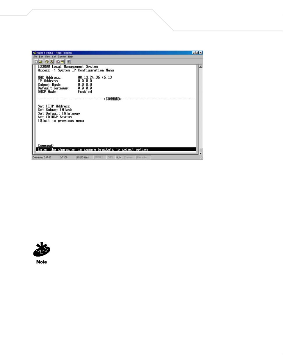
Switch Management Overview
To use the ES3000 Command Line Interface (CLI) to configure the device:
1. Use HyperTerminal (or other communications utility) to secure a connection to the ES3000
Ethernet Switch.
2. Hit the return key <Enter> to display the ES3000 logon screen.
3. Enter a user name of admin and password of symbol. Press Enter.
4. Select Execute CLI from the Main Menu. Press Enter.
1-7
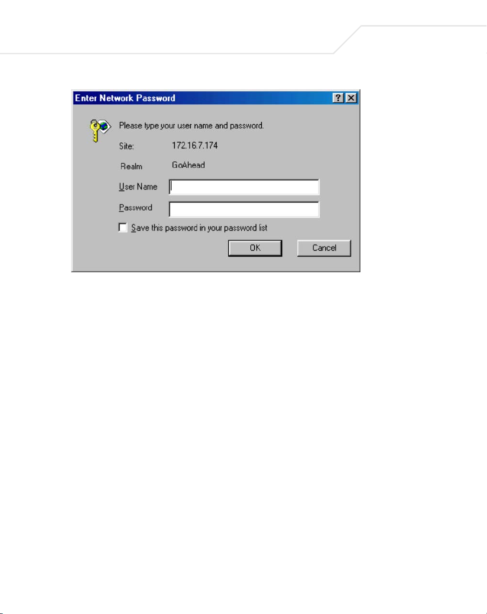
To use the ES3000 Web Management interface to configure the device:
A network connection is required between the device and the host to use the
Web Management interface to configure the device.
1. Access the Web interface (using a Web browser) by entering the switch IP address into the
address bar. Press Enter.
Internet Explorer 5.0 or later or Netscape Navigator 6.0 or later is required.
Page 20
1-8
ES3000 User Guide
2. Enter a user name of admin and password of symbol. Press OK.
The Web interface General Information page displays. Refer to Chapter 3 for information
on using the ES3000 serial interface to configure the device. Refer to Chapter 4 for
instructions on using the Web interface to configure the device. Refer to Chapter 5 for
instructions on using the CLI for device configuration.
Page 21
Switch Management Overview
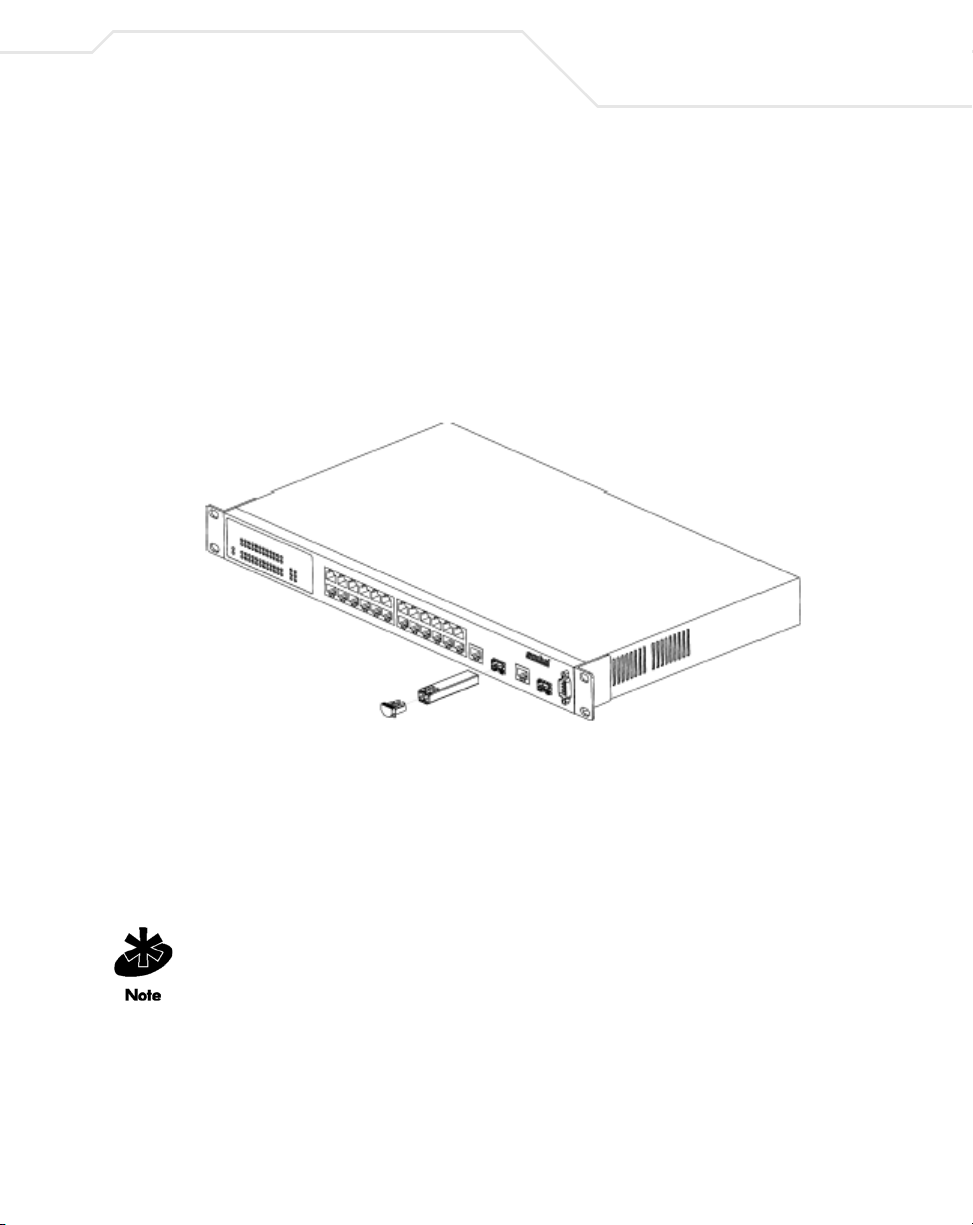
1.7 Installing a SFP Fiber Transceiver
The ES3000 Ethernet Switch supports a SFP (small form factor pluggable) fiber channel transceiver
used in fiber channel cable installations.
To install the SFP Fiber Transceiver:
1. Remove the rubber plug protecting the optics on the transceiver.
2. Insert the transceiver into the fiber transceiver cage available on ports 25 and 26 on the
ES3000 Ethernet Switch.
1-9
3. Ensure one of the following two cable types is used when connecting fiber cable to the
ES3000 Ethernet Switch:
• LC 62.5um/125um multimode fiber optic cable
• LC 50um/125um multimode fiber optic cable
4. Consult the System Administrator for cable length and installation specifications unique to
the installation environment.
If removing the SFP transceiver, disengage the locking mechanism on the SFP transceiver
carefully before removing the transceiver from the ES3000 Ethernet Switch.
Page 22

1-10
ES3000 User Guide
Page 23

Firmware Upgrades
Symbol periodically releases new versions of the firmware that runs on the ES3000 Ethernet
Switch. These software releases provide new features that can extend the useful life of the
ES3000 Ethernet Switch.
To upgrade software on the switch, boot the switch from a TFTP server instead of its own nonvolatile memory (NVRAM). To initiate the sequence, set the Next Boot From configuration
parameter to Boot from Net, and reset. When the Boot from Net option is set, the switch uses
an image residing on a TFTP server on the network. Ensure the TFTP server residing on the
network is accessible by the switch. Once completed, the software version requires verification
within the System page.
The PoE and non-PoE versions of the ES3000 switch use different versions of the bootcode and
runtime software. Do not attempt to use PoE software with a non-PoE switch. Do not attempt to
use non-PoE software with a PoE switch. Attempting to do so may render the switch inoperable.
Page 24

2-2
ES3000 User Guide
Symbol recommends using a RS-232 serial port connection to the switch during the software
upgrade. When using a Telnet Session or Web interface, the connection to the switch is not
available until the switch has completed its boot cycle and entered the Spanning Tree
forwarding mode. This can take up to three minutes.
To upgrade the switch firmware using the Web interface:
1. Go to Main Menu->Switch Tools Configuration->Software Upgrade Menu->TFTP
Software Upgrade.
2. Set the IP address and Image File Name.
3. Verify the IP address for the TFTP Server and the file name of the new software image are
accurate.
4. Verify the TFTP server and IP connection between server and switch are working properly.
5. Select Upgrade Image. The switch downloads the image from TFTP Server and replaces
the runtime image in Flash.
Page 25

Administration Console Access
The administration console is an internal, character-oriented, VT-100/ANSI menu-driven user
interface for management configuration activities. View the administration console from a
terminal, PC, Apple Macintosh, or UNIX workstation connected to the switch console port.
3.1 Direct Access Management Method
The direct access management method is required when initially setting up the switch.
Thereafter, Symbol recommends using the Web management access method (described in
Chapter 4) to manage the switch if unfamiliar with command line configuration. Advanced users
are recommended to use the CLI commands described in Chapter 5 to manage the switch.
Direct access to the switch console is available by connecting the switch console port to a VT100 or compatible terminal or to a PC, Apple Macintosh, or UNIX workstation equipped with a
terminal-emulation program. Use the null-modem cable supplied with the switch to secure the
connection.
Page 26
3-2
ES3000 User Guide
The following are Symbol recommended terminal-emulation programs:
• HyperTerminal (which is built into the Microsoft Windows operating systems)
• ZTerm (Apple Macintosh)
• TIP (UNIX workstation)
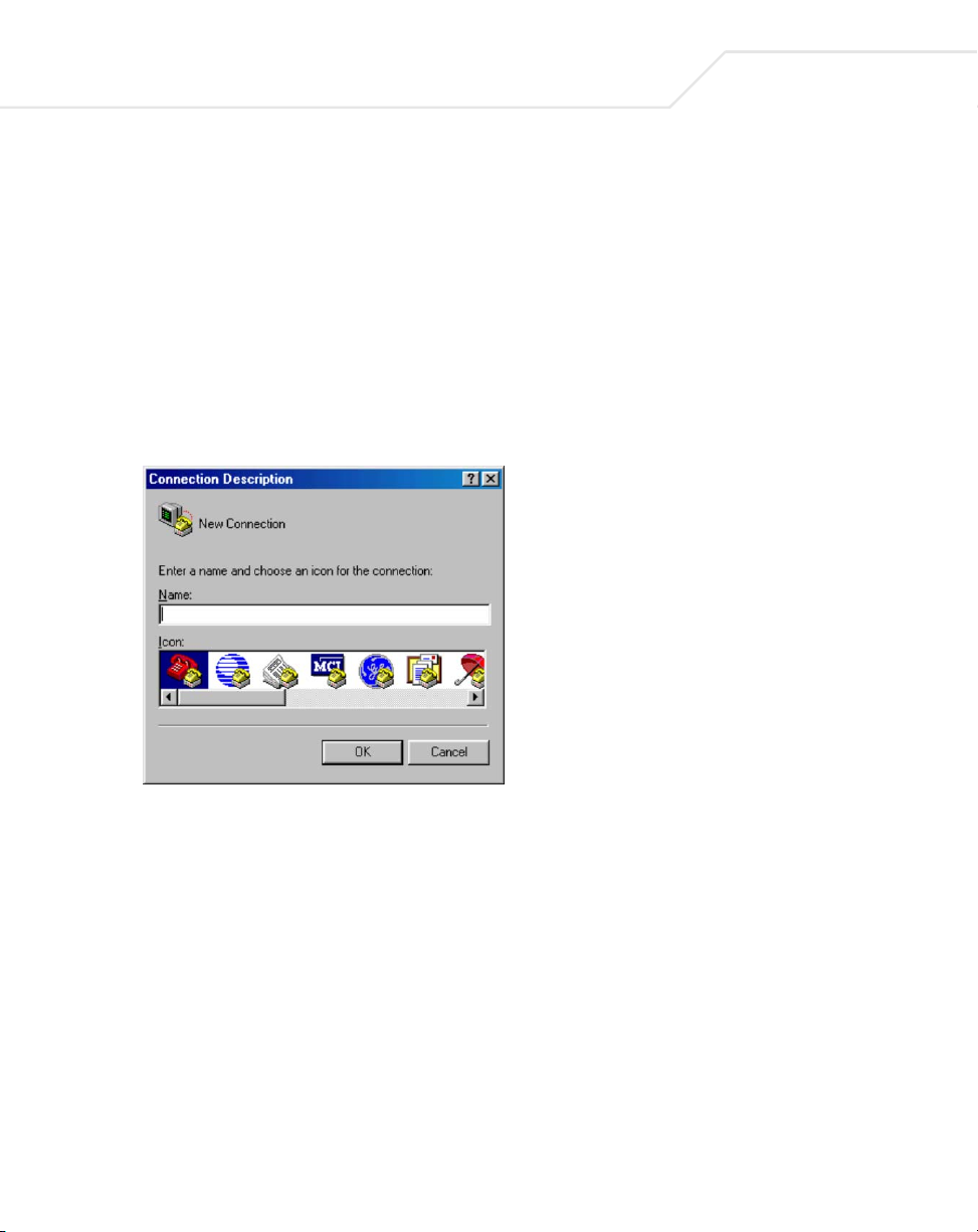
To set up the connection using a HyperTerminal on a PC (but other systems follow similar steps):
1. Click the Start button. Select Accessories and Communications.
2. Select HyperTerminal.
The Connection Description screen displays.
3. Enter a name for the connection. Click OK.
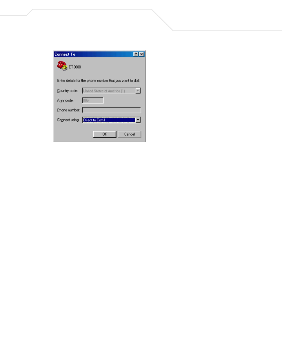
4. The Connect To screen displays. In the bottom, drop down box labeled Connect using,
choose the COM port the switch connects to. Click OK.
Page 27
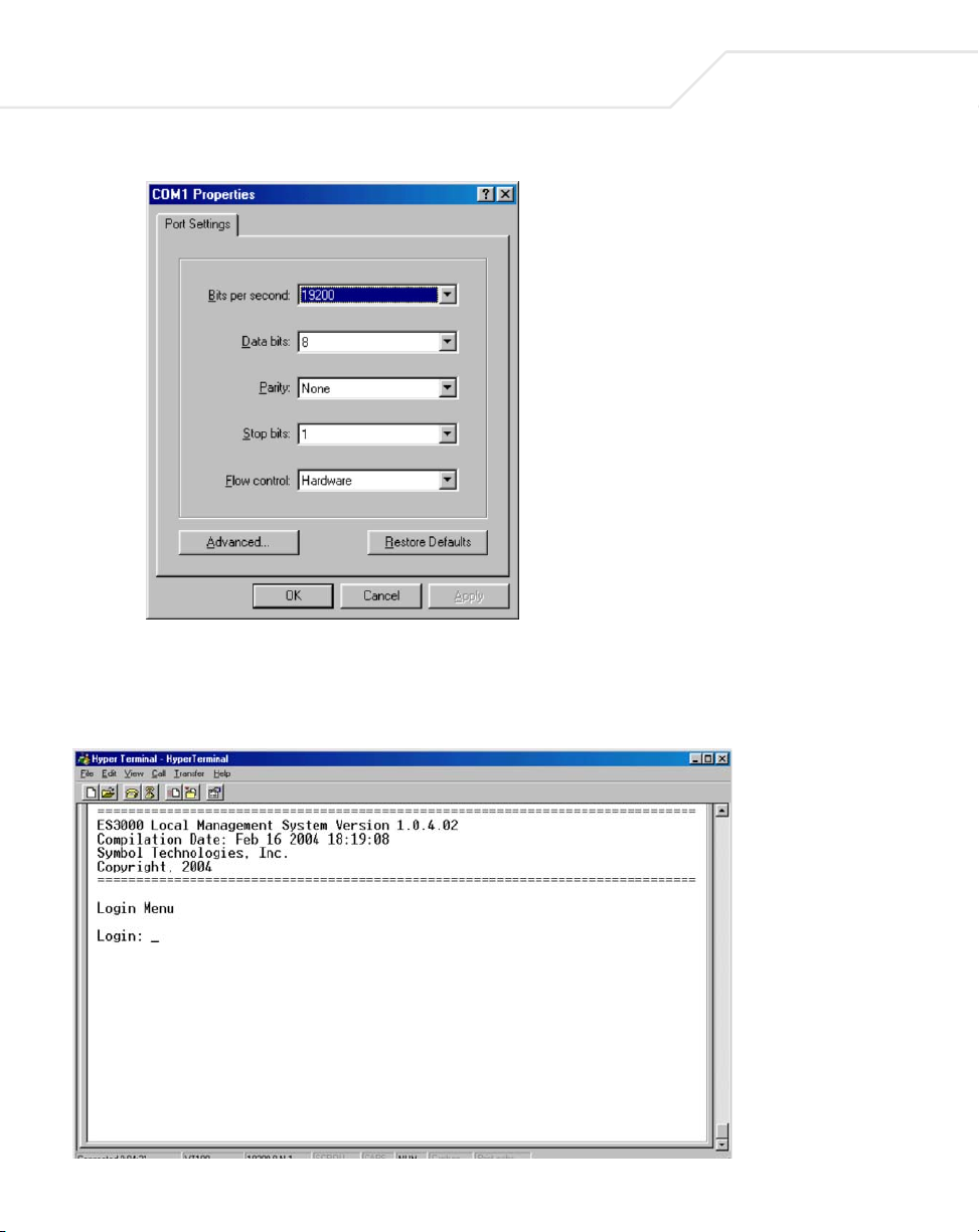
5. Verify the port settings are:
Baud Rate: 19200
Data Bits: 8
Parity: None
Stop Bits: 1
Administration Console Access
3-3
Flow Control: None
Page 28
3-4
ES3000 User Guide
6. Click OK.
When the HyperTerminal window displays, a connection exists to the switch and a logon
screen displays. If a login screen or main menu does not display, hit the return key.
Page 29

Administration Console Access
To use the arrow keys when attached to the User Interface via a Telnet Session to toggle forward and
backward. Choose Properties from the terminal pull-down menu and verify the VT100 Arrows
option is turned on.
3.2 User Interface
The switch provides a menu-driven interface for managing the switch, as well as a Command Line
Interface (CLI). The CLI uses text commands to manage the switch. The CLI is accessed through the
CMI. See Chapter 5 on page for detailed information on navigating the CLI.
3.3 Saving Configuration Changes
To save changes made within the menu-driven interface, refer to
Main Menu->System Admin.->Tools->Save Config. on page 3-24. Use the Save Config page to save
all updates to the menu-driven interface. Once updates are made refer back to the target
configuration page to ensure the updates have been implemented by the ES3000 Ethernet Switch.
3-5
Page 30

3-6
ES3000 User Guide
3.4 Main Menu Options
The main menu displays the submenus available. Select Enter when a highlighted option confirms
the choice of the specified submenu. The hotkey or letter within square bracket of each menu option
can also be typed to directly choose the option. There are ten main menu items to choose from:
• General Information
• System Administration
• Ports Configuration…
• VLANs Configuration
• IGMP Snooping Configuration
• Spanning Tree
• QoS Configuration…
• Execute CLI
•Quit
To logout of the user interface, select Ctrl-D anytime during the telnet session. The interface moves
back to the login screen (password enabled) or Main Menu (password disabled).
Page 31

Administration Console Access
3-7
Page 32

3-8
ES3000 User Guide
3.5 General Information
The General Information screen displays information on the operational state of the ES3000
Ethernet Switch. Use this information for general configuration information when accessing other
menu items.
• System up for System run time after boot up
• Boot Code Version The version and timestamp of boot code
• Runtime Code Version The version and timestamp of runtime code
• Hardware Information Hardware associated information
• Version Hardware revision version
• DRAM Size Size of DRAM on system
• Fixed Baud Rate Data rate on console port, set to 9600.
• Flash Size Size of Flash memory
• Administration Information
• System Name Name of system, user definable
• System Location Location of system, user definable
• System Contact Contact information, user definable
• System Address Information
• Default MAC Address MAC Address of system
• Default IP Address The default IP address, user definable
• Default Subnet Mask The default subnet mask, user definable
• Default Gateway The default gateway, user definable
• DHCP Mode Enables/Disables DHCP
Page 33

Administration Console Access
3-9
3.5.1 Main Menu->System Administration->System Configuration
Use the System Configuration screen to access System Name, Contact Person, and System
Location submenus required for configuring the device. The MAC address and Object ID also display,
but these items are not user configurable.
There are three submenus at System Configuration menu,
• Access Configuration
• SNMP Configuration
• Tools Configuration
Page 34

3-10
ES3000 User Guide
3.5.2 Main Menu->System Admin.->Access Configuration
There are three submenu options within the Access Configuration menu:
• IP Config.
• Management Access
•Quit
Use the IP Config menu to manage the IP related information for the ES3000 from the System IP
Configuration menu. Use the Management Access menu to enable or disable the Web, SNMP
and/or telnet interfaces from the Management Access menu.
Page 35

Administration Console Access
3-11
3.5.3 Main Menu->Access->System IP Configuration
Use the System IP Configuration menu to manage IP related information for the ES3000 supported
system.
• IP Assignment Mode
• Manual - Manually enter IP related information
• DHCP - The switch accepts DHCP broadcast from a DHCP server and automatically
configures IP related information
The default setting is DHCP. However, the user needs to know the IP address of the switch to remotely
manage it and DHCP assignments can change. Symbol recommends changing the IP assignment
mode from DHCP to manual after the switch as obtained its IP address. This creates a more stable IP
address.
If in manual mode and configuring IP information:
• Enter a site-specific IP address, Gateway Address, and Network Mask (or subnet mask).
Consult the network administrator for the information.
Page 36

3-12
ES3000 User Guide
•Press Ctrl-W to save any changes to NVRAM.
3.5.4 Main Menu->Access->Management Access
Use the Management Access screen to enable or disable the Web, SNMP, and/or telnet interfaces.
The Management Access menu can also be used to change the user name and password. User names
and passwords are case sensitive and can be up to 20 characters long.
Using telnet, the user can only enable/disable the Web Interface. The user cannot enable/
disable the telnet interface from the Management Access screen.
If the password is unknown, contact Symbol technical support at 1-631-738-2400 (in North America)
or 1-800-653-5350 (International).
Page 37

Administration Console Access
3-13
The configurable fields within the Management Access menu have the following values:
Set Console UI Time Out: Session is disconnected when the time out occurs
Set Telnet UI Time Out: Telnet session is disconnected when the time out occurs
Change Local User Name: Defines the name of the local user
Change Local Password: Changes the password of the local user
Enable/Disable Telnet Server: Enables or disables the system accessibility via telnet.
Enable/Disable SNMP Agent: Enables or disables the system accessibility via SNMP
Enable/Disable Web Server: Enables or disables the system accessibility via Web browser.
Page 38

3-14
ES3000 User Guide
3.5.5 Main Menu->System Admin->SNMP Configuration Menu
Simple Network Management Protocol (SNMP) is a messaging protocol allowing communication
between network managers and agents. An SNMP manager is part of a network management system
(NMS), allowing an administrator to manage the network by making requests to agents. An SNMP
agent provides an interface to a managed device containing managed objects in a management
information base (MIB).
At the request of an SNMP manager, an SNMP agent retrieves or stores values in the MIB, which
contains information about the device and network. The SNMP agent can also send asynchronous
traps, which alert the SNMP manager to certain conditions on the network. A trap could result from
improper user authentication, PoE power usage over threshold or network topology changes..
Use the SNMP Configuration menu to manage the ES3000 switch using the Simple Network
Management Protocol (SNMP) from a network management station. Configure the switch to
participate in the SNMP community and add the SNMP host agent to the host table. This prevents
unauthorized SNMP access to the switch from non-approved SNMP hosts.
SNMP management features on the switch include:
• Simple Network Management Protocol (SNMP)
• Support Standard MIBs:
• MIB II (RFC1213)
• Ethernet Interface MIB (RFC1643)
• Bridge MIB (RFC1493)
• Private Enterprise MIB
• 4-Group RMON (RFC1757)
Page 39

The SNMP Configuration page has four options:
• System Information
• Authorized Managers
• Trap Receivers
• Trap Selection
Administration Console Access
3-15
Page 40

3-16
ES3000 User Guide
3.5.6 Main Menu->SNMP Config.->System Information
Use the System Information page to display system information to set the system name, location,
and contact information. The MAC address and Object ID are also shown, but the MAC address and
Object ID are not user configurable.
Page 41

Administration Console Access
3.5.7 Main Menu->SNMP Config.->Authorized Managers
Use the Authorized Managers page to list the SNMP managers and their associated information.
There are two community strings in default mode, private and public. Read-only is allowed with public
and read-write is granted to private. Change the two community strings as required.
3-17
Four commands are available to set the Manager IP, community string, Status, Privilege, and IP
address.
Set Manager IP: Sets the IP address of a specified community. The access is
restricted to specified IP only.
Set Manager Community: Sets community string.
Set Manager Privilege: Sets the access privilege, 1 is Read-only and 2 is Read-Write.
Set Manager Status: Enables or disables a community string.
Page 42

3-18
ES3000 User Guide
3.5.8 Main Menu->SNMP Config.->Trap Receiver Configuration
When Authentication Traps is Enabled, the system generates an SNMP trap upon a host
authorization failure. The failure occurs when a host attempts to gain access to the system but the
host IP is not in the SNMP host table.
Authentication Failure Trap
Enable The system generates a SNMP trap upon a host authorization failure
Disable The authentication traps are not generated
All hosts in community strings with TRAP privileges are notified when a trap condition occurs.
Page 43

Administration Console Access
3.5.9 Main Menu->SNMP Config. ->Trap Selection
Three commands are available to configure individual trap parameters:
Enable/Disable Auth Fail Trap: Enables or disables the authentication failure trap.
Add Link Down Trap Ports: Add individual port onto the trap list.
Delete Link Down Trap Ports: Delete individual port from the trap list.
3.5.9.1 Port Link Down Trap
When on, the system generates an SNMP trap upon a port link down. This failure occurs when a link
is disconnected. Therefore, symbol recommends each port be enabled and/or disabled independently.
3.5.9.2 Link Down Trap
Enable The system generates a SNMP trap upon a port link down
Disable The port link down trap is not generated upon a port link down
As authentication failure trap, all hosts in community strings with TRAP privileges are notified when
a trap condition occurs.
3-19
Page 44

3-20
ES3000 User Guide
Page 45

Administration Console Access
3.5.10 Main Menu->System Admin. ->Tools Menu
The Tools Menu has six options:
• Software Upgrade
• System Reboot
• Save Config.
• Upload/Download Config.
•SNTP Config
•System Log
These individual menu options are discussed in detail in the sections that follow.
3-21
Page 46

3-22
ES3000 User Guide
3.5.11 Main Menu->System Admin.->Tools->Software Upgrade
If new improvements to the software on the switch become available, use the Software Upgrade
menu to upgrade the switch to the new software version. Once the IP address of the TFTP and the
name of the new software image file are properly configured, the user can upgrade the software with
command on this menu. See Chapter 2, Firmware Upgrades when updating software.
The previous version of runtime image is lost when the
procedure completes.
Use the Software Upgrade menu for:
• Setting the TFTP Server IP Address
• Setting the Image File Name
• Upgrading the Image
Page 47

Administration Console Access
3.5.12 Main Menu->System Admin.->Tools->System Reboot
When the system reboots, reboot Status and reboot Ty p e options display:
Reboot Status:
Stop The switch is powered down.
Normal The switch conducts a warm reboot as normal when rebooted.
Reboot Type:
Normal Reboot with current runtime code and configuration.
Factor-Default The switch runs as factor default after reboot. Symbol recommends
Factor-Default if the previous configuration crashed.
3-23
Page 48

3-24
ES3000 User Guide
3.5.13 Main Menu->System Admin.->Tools->Save Config.
Save updated settings to Flash once changes to the screens within the console interface have been
made. Use the Save Config screen as the central location to save changes made within the ES3000
Ethernet Switch menu-driven interface. Once updates have been saved to the system using the Save
Config page, refer back to the target configuration screen to ensure the changes have been
implemented by the ES3000 Ethernet Switch.
Select Save Configuration and use either Enter or Y to save the configuration to Flash.
Network IP settings (IP address, Gateway Address, Network Mask) are not be affected by
the Save Configuration command.
Page 49

Administration Console Access
3.5.14 Main Menu->System Admin. ->Tools ->Upload/Download Config.
There are four configurable functions within the Upload/Download Configuration page:
Set TFTP Server IP Address user can enter the server IP address to get the TFTP server.
Set Configuration File Name user can enter the file name that they want to config
Upload Configuration File user can upload the configuration file
Download Configuration File user can download configuration file from a TFTP server
3-25
Page 50

3-26
ES3000 User Guide
3.5.15 Main Menu->System Admin.->Tools->SNTP Config.
There are configurable functions in the SNTP Configuration page:
Set SNTP Server IP Simple Network Time Protocol, the user can enter SNTP server IP
to gain access.
Set SNTP Interval Set SNTP polling interval.
Set Time Zone Set the time zone
Set Daylight Saving Set the daylight saving… or ignore it
Page 51

Administration Console Access
3.5.16 Main Menu->System Admin.->Tools->System Log
The System Log is a tool for observing system behavior. Clear the system log by selecting Clear
System Log. Symbol recommends referring to the System Log when contacting the Support Center
to determine if an ES3000 event has been recorded.
3-27
Page 52

3-28
ES3000 User Guide
3.5.17 Main Menu->Port Configuration Menu
Use the Port Configuration menu to set the port characteristics related to link operations. All of the
parameters on the Port Configuration page are toggle settings. To change, or toggle, between
options, select Ctrl-M to move the curser to the ports field and strike the space bar when the
appropriate option is highlighted. To modify ports 17 to 26, tab through ports 1 to 16. The comments
field is available to enter a description of the port.
Page 53

Administration Console Access
3.5.18 Main Menu->Ports->Basic Port Config.
Use the Basic Port Configuration menu to configure port status (link type, admin enable/disable,
link up/down, mode, and flow control). To mirror other ports, select Port Mirroring.
3-29
Page 54

3-30
ES3000 User Guide
3.5.19 Main Menu->Ports->Basic Port Config.->Port Status & Config.
The Port Status & Configuration menu contains the following editable fields:
Ty pe
The type of a port, this field is not user configurable.
Admin field
Enables or disables the port.
Link
The status of a port. The status is Up when a port is connected and active.
Mode
Provides the choice of Full-duplex, Half-duplex, or Auto negotiation as well as speed selection among
10Mbps, 100Mbps, 1000Mbps, or auto negotiation. Enabling auto-negotiation on a port allows a port
to sense the communication speed and negotiate the duplex mode (full duplex or half duplex)
automatically. The ports select the highest possible throughput. The port can auto-negotiate with any
Page 55

Administration Console Access
port compliant with IEEE 802.3u. If the other port is not IEEE802.3u compliant, the port defaults to
half-duplex (10 Mbps mode). Users can operate the communication speed and duplex mode manually.
Flow Control
Enables or disables Flow Control. Flow control is a protocol preventing packets from being dropped
by reducing the amount of traffic to a level that can be accommodated. If enabled on both ends of a
connection, it prevents the sender from sending data until the receiver can accept it. This switch
complies with the IEEE802.3x flow control standard.
Gigabit Ports
The port type can be chosen for the two-gigabit ports on each switch. The default is the port using
the RJ-45 interface. Select the GBIC interface by plugging a GBIC connector. The GBIC interface has
higher priority than the shared RJ-45 interface.
Enabling the GBIC connector for a Gigabit Ethernet port disables the built-in 1000BASE-T
port. GBIC ports do not support Auto Negotiation. Manually configure the GBIC port. The
default values are 1000 Mbps, full duplex.
Five commands are available on the menu: Set Admin Status, Set Flow Control, Set Mode, Next Page,
and Previous Page.
3-31
Set Admin Status: Enable or disable the admin. status of a port.
Set Flow Control: Enable or disable flow control of a port.
Set Mode: Manually configure the speed and operation mode of a port. The first 24
ports have two speeds, 10 or 100Mbps while the last two gigabit ports
has three speeds, 10, 100, and 1000Mbps. Two operation modes, half
and full duplex, are available for 10 and 100Mbps but only full duplex is
allowed on 1000Mbps. When the command is issued, two short keys, A
and N, are displayed. The A stands for automatic and N stands for nonautomatic. Choose N to manually configure a port.
Next Page: Show the next 12 ports' information.
Previous Page: Show the previous 12 ports' information.
Page 56

3-32
ES3000 User Guide
3.5.20 Main Menu->Ports->Basic Port Config->Port Counters
Use the Port Counters menu to select the port where information is required. Refer to the Total and
Avg./s lists for individual port information. Reset the ES3000 to retrieve the latest information
immediately. The Refresh mode is to set to a defined refresh interval.
Page 57

Administration Console Access
3.5.21 Main Menu->Ports->Basic Port Config->Port Mirroring
Port mirroring allows one port on the ES3000 to see all of the packets passing through any other port
on the switch. Usually, a network analyzer is attached to the monitoring port so the network
administrator can debug problems with the monitored port.
The ES3000 has two gigabit Ethernet ports, ports 25 and 26. A 10/100BaseT port would not be able
to keep up with the packet flow on a gigabit port. Only another gigabit port may monitor a gigabit
port. Any port on the ES3000 may be used to monitor ports 1 through 24, the 10/100BaseT ports.
Use the Port Mirroring menu to designate a port for monitoring traffic from a listed port or a single
VLAN on the switch. The switch monitors network activity by copying traffic from the specified
monitoring sources to the designated monitoring port. There are four commands within the menu:
Set Monitoring Port: Sets the monitoring port. All traffic is forwarded to this port.
Set Port to be Monitored: Sets the monitored port. All traffic through this port is
forwarded to the monitoring port.
Set Traffic Direction: Sets the direction of monitored traffic, receiving(R),
transmission(T), or both direction(B).
Change Mirror Status: Enables or disables the mirror status.
3-33
Page 58

3-34
ES3000 User Guide
3.5.22 Main Menu->Ports->Port Security
Use the Port Security screen to enable or disable the Web, SNMP, and/or telnet interfaces or
change the user name and password. User names and passwords are case sensitive and can be up
to 20 characters long.
When using telnet, the user can only enable/disable the Web interface. The user cannot
enable/disable the telnet interface.
There are two functions in the Port Security page:
•Radius
• 802.1x
Page 59

Administration Console Access
3.5.23 Main Menu->Ports->Port Security->Radius
Use the Radius menu option to configure the advanced security settings of the switch to limit the
access to the management interfaces. There are two advanced security options beyond the basic
password protection: RADIUS client authentication and 802.1X port authentication. If the user has a
RADIUS server on the network, authentication of management access can be conducted through the
RADIUS server. This does not affect traffic passing through the switch, but only authenticates access
to the switch management. The same is true for 802.1X port authentication. Allow only users with
specific IP addresses to access the management features, thus preventing unauthorized personnel
from accessing the switch. The 802.1X is located in the Advanced Switch Configuration->Port Base
Access Control Configuration Menu.
3-35
Page 60

3-36
ES3000 User Guide
3.5.24 Main Menu->Ports->Port Security ->802.1x
Use the 802.1x menu to configure the NAS ID used for connection, the port to pass the security, the
port control type, the operational or administrative control direction, the transmission period (30sec.),
the supplicant requiring and server responding time, the maximum request times and the quiet period
if there is no any activity on the ES3000.
Configure the up re-authentication period when re-authentication status is Enabled. Go back to the
initial status by initializing or re-authentication initializing.
Page 61

Administration Console Access
3.5.25 Main Menu->Ports->Power over Ethernet
Use Power-over-Ethernet (PoE) to eliminate using a 110/220 VAC power source to power access
points and other devices on a wired LAN. If using a Power-over-Ethernet system, only a single CAT5
Ethernet cable carrying both power and data to each device is required. The single cable scheme
provides greater flexibility in the placement of access points and network devices and can
significantly decrease installation costs.
Two configuration pages exist for the PoE function. The first allows per port configuration for specific
power restrictions on an individual port basis. The second configuration page is used for global
configurations that apply switch-wide.
3-37
Two functions are provided for the PoE control,
Port Configuration
Admin. status: The status of administration for a port.
Priority: Priority of a PoE port. Three selections are available, critical, high, and low.
When the power consumption over the power budget, the critical has higher
priority on power supplying.
Limit(mW): The maximum power supplied to a port. The default is 15.4W or 15000mW.
Page 62

3-38
ES3000 User Guide
Global Configuration
Power Usage: Sets the power usage threshold for sending a trap.
Management Method: The action to take when the power sink over the power budget, use
one of the following:
1) Low priority port is shut down;
2) Deny next port connection.
Detection Method: Enables or disables the power capacitor detection.
Page 63

Administration Console Access
3-39
Page 64

3-40
ES3000 User Guide
3.5.26 Main Menu->Ports->Link Aggregation
Use the Link Aggregation menu to allow multiple links between switches to work as one virtual link
(aggregate link). Trunks can be defined for similar port types only. For example, a 10/100 port cannot
form a Port Trunk with a gigabit port. For 10/100 ports, trunks can only be formed within the same
bank. A bank is a set of eight ports. Up to four trunks can be operating at the same time. Toggle the
ports to the correct trunk number to set up a trunk.
Click Apply to enable the trunk. Spanning Tree treats trunked ports as a single virtual port.
Page 65

Administration Console Access
3.5.27 Main Menu->Ports->Link Aggregation->LA Config
Use the LA Configuration menu to define multiple links between switches to work as one virtual link
or aggregate link. Trunks can be defined for similar port types only. For example, a 10/100 port cannot
form a Port Trunk with a gigabit port. Spanning Tree treats trunked ports as a single virtual port.
Straight-though cables are required for all links in the trunk. Do not use crossover cables.
Disable auto-negotiation on the ports in a trunk prior to setting up the trunk.
3-41
Page 66

3-42
ES3000 User Guide
3.5.28 Main Menu->Ports->Link Aggregation->Set Port Priority
The default system priority is the same in all ports. If configuring a port with different priority in the
link aggregation, go to set port priority to configure the port priority.
Page 67

Administration Console Access
3.5.29 Main Menu>VLANs
A Virtual Local Area Network (VLAN) is a means to electronically separate ports on the same switch
from a single broadcast domain into separate broadcast domains. By using a VLAN, users can group
by logical function instead of physical location. There are 4096 VLANs supported on this switch. Two
memberships are available for a VLAN member, tagged and untagged, abbreviated as T and U,
respectively. If a port is an untagged member of a VLAN, the VLAN tag is striped from the frame
before it is sent out that port. If the port is a tagged member of a VLAN, the VLAN tag stays in the
frame when sent. If a port is not a member of the particular VLAN, it does not get any traffic for that
VLAN. The VLAN tagging option is a standard set by the IEEE to facilitate the spanning of VLANs
across multiple switches.
All untagged packets entering the switch by default are tagged with the ID specified by the port ID.
Use the VLAN screen to specify the VLAN ID for each port. The number next to each port indicates
which ID is set for each port. Following industry standards, ID 1 is the default ID.
Up to 4094 VLANs with unique ID numbers and names can be added. VLAN ID numbers are required
to be within 1-4094. Per industry standard, the default VLAN has an ID of 1.
VLAN ID #1 cannot be deleted under any circumstance.
3-43
Page 68

3-44
ES3000 User Guide
3.5.30 Main Menu->VLANs->VLANs by VLAN-ID
Create a new VLAN, add new ports to an existing VLAN, remove ports from an existing VLAN, delete
a VLAN, Set Management Status, and/or Set GVRP Status from the VLAN by VLAN-ID screen. Six
commands are available:
Create VLAN: Creates a new VLAN, a unique ID is required.
Delete VLAN: Deletes a VLAN ID. The entire setup for the VLAN is erased.
VLAN # 1 cannot be deleted under any circumstance.
Config. VLAN Member: Configures the member of a VLAN
Set Port Config. Sets the configuration of a specified port
Set GVRP Status: Enables or disables the GVRP switch-wide.
Set Management Status: Enables or disables the management status of a static VLAN.
Page 69

Administration Console Access
3-45
To create a new VLAN Group:
1. Select Create VLAN.
2. Enter the VLAN ID and name in the provided fields.
3. Add VLAN members if so desired.
4. Click Apply.
To delete a VLAN Group:
1. Select Delete VLAN.
2. Give the corresponding VLAN ID.
To configure a VLAN Member:
1. Select Delete VLAN.
2. Give the corresponding VLAN ID.
Page 70

3-46
ES3000 User Guide
To set the GARP VLAN registration protocol (GVRP) message status (GARP refers to General Attribute
Registration Protocol):
1. Select Set GVRP Status.
2. Choose E to enable and D to disable.
To set Management Status:
1. Select Set Management Status.
2. Choose E to enable and D to disable.
Adding a VLAN
To create a VLAN:
1. Select Create VLAN.
The Create VLAN screen displays.
2. Create the VLAN and set the VLAN ID.
3. Enter the egress port of members by typing p.
Instead of typing 3 to 12 individually, a (-) can be used to indicate contiguous numbers. Use
a comma to separate the members.
Page 71

Administration Console Access
3.5.31 Main Menu->VLANs->VLAN Port Configuration Menu
Use the VLAN Port Configuration screen to configure VLAN configurations for each port. The PVID
is default to 1 for every port.
3-47
Set Port VID: Sets PVID of a port.
Set Frame Type: Sets the acceptable frame types, All or Tagged Only. When Tagged Only
is selected, all non-tagged packet are dropped.
Set GVRP Status: Enables or disables the GVRP of a port.
When a PVID on VLAN configuration is deleted, the PVID is changed to the default value of
PVID, 1. All other configurations are kept.
The following entry is used when PVID 2 is removed.
Port PVID Acceptable Frame Type GVRP
3 1 Tagged Only Enable
Page 72

3-48
ES3000 User Guide
3.5.32 Main Menu->IGMP Snooping Configuration Menu
The Internet Group Management Protocol (IGMP) is an Internet protocol allowing a host to report its
multicast group membership to multicast routers. Multicasting allows one computer on the Internet
to send information to other computers having identified themselves as interested in receiving the
information. The ES3000 can “snoop” the messaging protocol to keep track of multicast groups and
to insure multicast traffic is sent only to the appropriate ports within a VLAN. In networks where
multimedia applications generate multicast traffic, IGMP can reduce unnecessary bandwidth by
limiting traffic forwarding otherwise broadcast to the network. Enabling IGMP allows individual ports
to detect IGMP queries, report packets, and manage IP multicast traffic through the switch.
IGMP Snooping Config.
VLAN Filter Table
Router Port Table
IGMP Snooping Status
Enable The system detects IGMP queries, report packets, and manages IP
multicast traffic through the switch.
Disable The switch forwards traffic and disregards any IGMP requests.
Page 73

Administration Console Access
3.5.33 Main Menu->IGMP Snooping->IGMP Snooping Config.
Enable The system detects IGMP queries, report packets, and manage IP
multicast traffic through the switch.
Disable The switch forwards traffic and disregards any IGMP requests.
Users can set up Host port aged time and router port aged time to snoop the network and the IGMP
Snooping status report interval.
3-49
Page 74

3-50
ES3000 User Guide
3.5.34 Main Menu->IGMP Snooping->VLAN Filter Table
Use the VLAN Filter Table to define the VLAN not to be included in the set Vlan Filter. Enter the
VLAN ID (1-4094) in the VLAN ID field. Ensure the Status field is set to Filter.
Page 75

Administration Console Access
3.5.35 Main Menu->IGMP Snooping->Router Port Table
The Router Port Table menu displays the ports in a VLAN ID connecting to the router. The user can
snoop the package from the router side of the ports. Select Next Page to display additional VLAN
IDs should they exist.
3-51
Page 76

3-52
ES3000 User Guide
3.5.36 Main Menu->Spanning Tree Configuration Menu
The ES3000 can be configured to use one of three spanning tree protocols. Spanning Tree Protocol
(STP) is compatible with legacy equipment. Rapid Spanning Tree Protocol (RSTP) is signficantly faster
than STP. Multiple Spanning Tree Protocol (MSTP) is based on RSTP and extends RSTP in a way that
is useful for switches implementing VLANs.
There maybe more than one physical path between any two nodes (forming a loop) either created for
redundancy or by accident. STP ensures only one physical path is active and the others are blocked.
If a loop is created for redundancy, STP monitors the two paths and activates the stand-by path if the
primary path fails. If a loop was created inadvertently, STP disables one of the two paths. A loop can
disable the network by causing a "Broadcast Storm", the result of a broadcast message traveling
through the loop again and again.
Use the Spanning Tree Configuration menu to access and configure the following submenus:
• Forwarding DB
• MSTP Config.
Page 77

Administration Console Access
3.5.37 Main Menu->Spanning Tree->Forwarding DB
Use the Forwarding Database option to view the dynamic MAC addresses currently in the address
database. When addresses are in the database, the packets intended for those addresses are
forwarded directly to those ports. The Administrator can display addresses in the table by port, VLAN,
and/or MAC address by entering the short key. The static MAC address table is also displayable
3-53
There are four commands within the Forwarding Database option.
Static Address Table Display and configure the static MAC address table.
Display MAC Address By Port Display MAC address table for a specified port
Display MAC Address by MAC Display MAC address in order of MAC address.
Display MAC Address by VID Display MAC address table for a specified VLAN ID.
Page 78

3-54
ES3000 User Guide
Static Address Table:
Use the Static Addresses Table to specify Media Access Control (MAC) addresses for specific ports
not purged from the bridge table by the aging function. There are 3 entries in the table. Two
commands are available to add and/or remove an entry. To add an entry, follow the pop-out prompt.
1. Enter MAC Address(xx:xx:xx:xx:xx:xx) > 00:12:34:99:ab:ef <ENTER>
2. Add new entry->Enter port number > 10 <ENTER>
3. Add new entry->Enter VLAN ID> 50 <ENTER>
A new entry displays: 00:12:34:99:AB:EF 10 50
To remove an entry:
1. Hit key D
2. Enter MAC Address(xx:xx:xx:xx:xx:xx) > 00:11:ab:00:33:55 <ENTER>
3. Delete entry->Enter VLAN ID> 30 <ENTER>
Display MAC Address by Port, MAC, and VID
With the number of hosts increase on a network, the Forwarding Database grows sharply. To look for
an MAC address becomes time-consuming work. The system provides three different ways for
administrator to research MAC addresses; by a specified Port, sorted by MAC address, and by a
specified VLAN. Each one of these, a Set Age-Out time command is given to configure the time to
remove a non-recently-used entry. The modification on this timer is switch-wide.
The age-out time is the amount of time that an entry is kept in the bridge tables prior to being purged
(or aged). The range is between 10 seconds and 1,000,000 seconds. By industry standard, 300
seconds is the default.
Page 79

3.5.38 Main Menu->Spanning Tree->MSTP Config.
Administration Console Access
3-55
3.5.39 Main Menu->Spanning Tree->Multiple Spanning Tree Configuration->MSTP Config.
Rapid spanning tree (IEEE 802.1w) is supported to reduce the spanning tree established time. Each
spanning tree establishment process takes several timeouts to avoid a loop, even the edge switch.
The user can configure the switch to avoid the long latency due to timeouts if there is only a single
connection to the switch. If two or more links to the switch exist and Rapid Spanning Tree is enabled,
the switch might not perform properly.
The switch supports IEEE 802.1s Multiple Spanning Tree. An independent spanning tree can be
established per VLAN.
Page 80

3-56
ES3000 User Guide
The upper half of the MSTP Config screen displays information about the Multiple Spanning Tree
Configuration.
Status:
Global MSTP Status: Status of global multiple spanning tree protocol. Enabled
indicates that MSTP is running while Disabled indicates
MSTP is not running.
Protocol Version: Three protocol versions are available, SPT (Spanning
Tree), RSPT (Rapid Spanning Tree), MSPT (Multiple
Spanning Tree).
MST Config ID Selector: Reserved for future use
MST Region Name: The MST Region Name is required to be identical to other
switches to work cross-switch.
Page 81

Administration Console Access
MST Region Version: Like MST Region Name, the MST Region Version name is
required to be identical to other switches to have work
cross-switch.
MST Config Digest: Digest value of configuration data to increase the
security.
Command:
Enable/Disable Global MSTP: Enables or disables the switch-wide MSTP.
Set MSTP Protocol Version: Sets the protocol to be one among SPT (Spanning
Tree), RSPT (Rapid Spanning Tree), and MSPT
(Multiple Spanning Tree).
Cist Configuration: Configure Common Instant Spanning Tree - a switch-
wide configuration.
Cist Basic Port Configuration: Port Configuration on Common Instant Spanning Tree -
a switch-wide configuration.
Cist Advanced Port Config: Advanced Port Configuration on Common Instant
Spanning Tree - a switch-wide configuration.
3-57
Set MSTI Region Name: Sets the region name.
Set MSTI Region Version: Sets the region version.
Designated Topology Info: Designated topology information includes Port, Trunk,
Link status, CIST Designated Root, CIST Designated
Cost, CIST Designated Bridge, and CIST Designated
Port.
Regional Topology Info: Regional topology information includes Port, Trunk,
Link status, CIST Port Regional Root, CIST Port
Regional Path Cost.
Configure the switch to ensure the SPT works properly. The Common Instant Spanning Tree
Configuration Menu enables the user to configure the switch-wide parameters, such as Cist Hello
Time, Cist Maximum Age, and Cist Forward Delay.
Page 82

3-58
ES3000 User Guide
3.5.40 Main Menu->Spanning Tree->CIST Config.
Status
Hello Time: Time between configuration messages sent by the Spanning Tree
algorithm
Maximum Age: The time before a configuration message is discarded by the system
Forward Delay: The time the system spends transitioning from the learning to the
listening to the forwarding states
Bridge Priority: Priority setting among other switches in the Spanning Tree
Command
Set Cist Bridge Priority: Sets the Cist bridge priority.
Set Cist Bridge Hello Time: Sets the interval between two hello packets.
Set Cist Bridge Maximum Age: Sets the maximum age time.
Set MSTP Max Hop Count Delay: Sets the maximum hop count delay.
Page 83

Administration Console Access
Rapid Spanning Tree
When a port running the standard STP is connected, it goes through the STP negotiation
(listening -> learning -> forwarding or blocking) before it is available. If a client is trying to access a
server through the switch running STP negotiation, it is not able to connect to it immediately. This can
be a problem for some networks. RSPT solves the problem by setting the port directly to forwarding
mode. Therefore, any server access request is forwarded. RSPT is used on end node ports (ports
connected to PCs or servers) and not on uplink ports to other switches.
3-59
Page 84

3-60
ES3000 User Guide
3.5.41 Main Menu->Spanning Tree->MSTP Config->CIST Basic Port Config.
Use the CIST Basic Port Config. menu to configure the port edge status, port P-TO-P status, and
restart port migration to prevent the wrong link.
Page 85

Administration Console Access
3.5.42 Main Menu -> Spanning Tree -> MSTP Config. -> CIST Advanced Port Config.
Use the CIST Advanced Port Config. menu to set up the port edge status, port P-TO-P status, and
restart port migration to prevent the wrong link.
3-61
Page 86

3-62
ES3000 User Guide
3.5.43 Main Menu->Spanning Tree->MSTP Config.->MSTP Instance Config.
A small tree instance can be considered in the MSTP. One Instance can have more than one VLAN.
Use the MSTP Instance Config. menu to add or remove a VLAN, or remove the MST Instance as
well as MST Instance and Instance Port configuration.
Page 87

Administration Console Access
3.5.44 Main Menu->Spanning Tree->MSTP Config.->Designated Topology Info.
The Designated Topology Info. page displays read-only topology information for each port.
3-63
Page 88

3-64
ES3000 User Guide
3.5.45 Main Menu->Spanning Tree->MSTP Config.->Regional Topology Info.
The Regional Topology Info. page displays regional topology information (read-only) for each port.
Page 89

Administration Console Access
3.5.46 Main Menu->QoS (Quality of Service Configuration Menu)
The ES3000 implements IEEE 802.1p Quality of Service (QoS) processing. QoS policies examine
packets and classify them. The classification is used to drop packets or to assign markers to the
packets. The markers are Class of Service (CoS) Priority, Type of Service (ToS) Precedence and
Differentiated Services Code Points (DSCP). For each port, the outgoing packets are then placed in
four output queues based on CoS priority or DSCP value. The queues are serviced using a weighted
round robin algorithm.
Quality of Service defines the methods to improve network performance by segregating traffic.
Configure the switch for specific traffic to take priority by using either the VLAN tags (port-based) or
DSCP (DiffServ).
3-65
Page 90

3-66
ES3000 User Guide
3.5.47 Main Menu->QoS->Policy Config.
Differentiated Service (DiffServ) uses a priority tag in the data packet (the Differentiated Service Code
Point or DSCP) to determine the priority of the packet. The Policy Config menu maps the various
DSCP tags to the two four queues on each port. The Classifier allows users to add different rules to
distinguish traffic service. An administrator is able to classifier based on Protocol, Source MAC
Address, Source IP Address, Destination MAC Address, Destination IP Address, VLAN ID, DSCP,
Source Layer 4 Port, and Destination Layer 4 Port.
To create an applicable policy, the administrator configures conditions properly and apply these
conditions to policy by in-profile action or out-profile action, or no-match action.
Symbol recommends remembering those IDs given to Classifier, In Profile Action, No Match Action,
and Out Profile Action. If necessary, the administrator can retrieve the ID associated information from
the Show Each ID Information command.
Page 91

Administration Console Access
3.5.48 Main Menu->QoS->Queue Config.
Port Prioritization allows the user to specify which ports have greater precedence in situations where
traffic can be buffered in the switch due to congestion. Traffic that comes in on ports with a setting
of high is transmitted before those that come in on a port with a normal setting. The settings on this
page only affect packets that do not already have VLAN priority tags. To raise the priority of a given
port, toggle the port setting from normal to high. The default setting for a port is normal.
The priority tag of each packet is divided into four queues on each output port. The default setup is
that each queue takes two priorities sequentially. The Administrator can configure the traffic class as
needed. The Quality of Service works only after the QoS status is enabled by Set QoS Status.
3-67
Page 92

3-68
ES3000 User Guide
3.5.49 Main Menu->QoS->Queue Config.->Queue Mapping
The priority tag of each packet is divided into four queues on each output port within the Queue
Mapping screen. The default setup each queue assuming two priorities sequentially.
Configure the traffic class as needed. Quality of Service works only after the QoS status is Enabled
by Set QoS Status.
Page 93

Administration Console Access
3.5.50 Main Menu->QoS->Rate Limiting
Use the Rate Limiting screen to configure the broadcast storm control to enable or disable traffic
control in the networks.
Rate limiting, or storm control, prevents ports on the ES3000 switch from being overwhelmed by a
broadcast, unicast, or multicast storm. A storm results when packets flood the LAN, which degrades
network performance. With rate limiting enabled, the switch monitors incoming traffic by counting
packets over a period of time. When the packet count exceeds a predefined threshold level, the
switch suppresses traffic until the packet count drops below the threshold. With rate limiting
disabled, all traffic is allowed. The switch supports rate limiting for broadcast, multicast, and unicast
(DLF) traffic, keeping a separate count of the packets for each type of traffic. When broadcast or
unicast traffic reaches the threshold, the switch suppresses further traffic of that type until traffic
falls below the threshold. Broadcast, multicast and DLF traffic cannot be set on a per port basis, only
on a per-switch basis.
Select Broadcast Storm Control to display the Broadcast Storm Control Configuration Menu
used configuring switch behavior during a broadcast storm. A loop in a network can disable the
network by causing a Broadcast Storm. A Broadcast Storm is the result of a broadcast message
traveling through the loop again and again.
3-69
Page 94

3-70
ES3000 User Guide
3.5.51 Main Menu->QoS->Rate Limiting->Broadcast Storm Control Configuration Menu
Use the Storm Control Configuration page to set the limitation of broadcast, multicast, and/or DLF
(Destination Look Failure) packets delivered to the CPU. Each kind of packet determines the network
load. When the load reaches a certain threshold, the CPU is busy handling packets and is unable to
respond to other requests (configuration commands or SNMP requests). Available network
bandwidth decreases. The administrator can enable storm control to limit traffic in the networks.
There are three kinds of storm control; DLF, Broadcast, and Multicast.
DLF: Destination Look Failure packets. DLF packets are broadcast to all ports except
the incoming port.
Broadcast: Packets are delivered to all ports except the incoming port as DLF packets.
Multicast: Packets are delivered to all ports with group membership.
Storm control can either be Enabled and Disabled. When Enabled, the CPU drops packets beyond the
specified threshold. Otherwise, the CPU processes these packet types without any limitations. The
default setting is Disabled for all three packet types.
Page 95

Administration Console Access
3.5.52 Execute CLI
The CLI (Command Line Interface) provides a means to configure the system for advanced users.
Symbol recommends the CLI for adavanced users who do not need to navigae a menu-driven interface
to configure the ES3000 Ethernet Switch. See Chapter 5 for detailed information. Once Run CLI is
selected, the 'SW24P4>' prompt displays
3-71
Page 96

3-72
ES3000 User Guide
Page 97

Web Management Access
The Symbol ES3000 Managed Switch provides a built-in browser interface for configuring and
managing remotely using a standard Web browser such as Microsoft Internet Explorer or
Netscape Navigator. The browser interface also allows for system monitoring of the Switch. The
help page covers many of the basic functions and features of the switch and its Web interface.
When configuring the switch for the first time, assign an IP address and subnet mask to the
switch. Thereafter, access the Web interface directly using a Web browser by entering the
switch IP address into the address bar. Use the Web browser to manage the switch from a central
location, as if the user were directly connected to the switch console port.
When using the Web interface, changes are required to be saved or updates are lost. See
System Admin->Tools->Save Configuration on page 4-14 for additional information.
Web Management requires either Microsoft Internet Explorer 5.0 or later or Netscape Navigator
6.0 or later.
To connect to the switch, the switch IP is required to be known first. If using a private IP address,
172.16.7.174. By entering 'http://172.16.5.115/' on the URL, following login screen is shown.
Page 98

4-2
ES3000 User Guide
4.1 General Information
The General Information screen is a welcome page displaying system information. There are no
editable parameters on the screen.
Use the General Information page to access the following submenus:
System Admin Configure IP address information, management access and user
information
Ports Configure port security, PoE and link aggregation.
VLANs
IGMP Snooping
Spanning Tree
QoS Create Policy, create classifier and set in-profile and out-profile actions.
Create VLANs, Set VLAN IDs and create/modify 802.1q trunk.
Enable IGMP Snooping and VLAN filtering,
MSTP configuration, basic and advanced MSTP port configuration.
Each submenu item has its own set of options for configuring the ES3000 Ethernet Switch by a
specific functional area.
Page 99

Web Management Access
4-3
4.2 Saving Web Interface Configuration Changes
To save changes made within the Web interface, refer to
System Admin->Tools->Save Configuration on page 4-14. Use the Save Configuration page to save
all updates to the Web interface. Once updates are made, refer back to the target configuration page
to ensure the updates have been implemented by the ES3000 Ethernet Switch.
Page 100

4-4
ES3000 User Guide
4.2.1 System Admin->Access->IP Configuration
The IP Configuration menu manages the IP related information of the system.
To manually configure the IP address:
1. Enter a site-specific IP address, Gateway address and Net mask.
2. Click Apply to change the IP settings.
3. Save the Configuration to Flash and reset the system to implement the changes.
 Loading...