

Page 1
FOREWORD
http://www.motorcycle.in.th
This manual con tains an intro ducto ry de scri ption o n
the SUZUKI UY125/S and procedures for its inspection/service and ov erhau l of its main com pon ents.
Other info rm ation co ns ider ed as ge ner ally kno wn is
not included.
Read the GENERAL INFORMATION section to
familiarize yourse lf with t he motorcycl e and its m aintenance. U se this s ection a s well as o ther sectio ns
to use as a guide for proper inspection and service.
This manua l will hel p you kn ow the motor cycle better so that you can assure your customers of fast
and reliable service.
GROUP INDEX
GENERAL INFORMATION
PERIODIC MAINTENANCE
ENGINE
1
2
3
* This manual has been p repared on the ba sis
of the latest specifications at the time of publication. If modifications have been made since
then, differen ces may exi st betwe en the c ontent of this manual and the actual motorcycle.
* Illustrations i n this manu al are used to show
the basic principles of operation and work
procedures. They may not represent the
actual motorcycle exactly in detail.
* This manual is wr itten for persons who h ave
enough know ledg e, s kills a nd tools, i nclud in g
special tools, for se rvicing SUZUKI motorcy cles. If you do not ha ve the proper knowledge
and tools, ask your authorized SUZUKI
motorcycle dealer to help you.
!
Inexperienced mechanics or mechanics
without the proper tools and equipment
may not be able to properly perform the
services described in this manual.
Imprope r repair may result in in jury to the
mechanic and may render the motorcycle
unsafe for th e rider and passenger.
FUEL AND LUBRICATION
SYSTEM
CHASSIS
ELECTRICAL SYSTEM
SERVICING INFORMATION
4
5
6
7
© COPYRIGHT THAI SUZUKI MOTOR CO., LTD. 2005
THAI SUZUKI MOTOR CO., LTD.
Page 2
HOW TO USE THIS MANUAL
http://www.motorcycle.in.th
TO LOCATE WHAT YOU ARE LOOKING FOR:
1. The text of this manual is divided into sections.
2. The section titles are listed in the GROUP INDEX.
3. Holding the manual as shown at the right will allow you to find
the first page of the secti on easily.
4. The contents are listed on the first page of each section to
help you find the item and page you need.
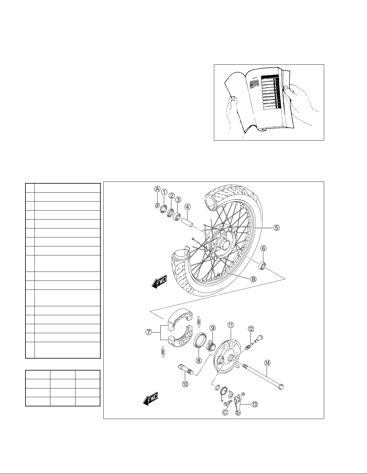
COMPONENT PARTS AND WORK TO BE DONE
Under the name of each system or unit, is its exploded view. Work instructions and other service information
such as the tightening tor que, lubricating points and locking agent points, are provided.
Example: Front wheel
1 Spacer
2 Dust seal
3 Bearing
4 Front wheel spacer
5 Front wheel
6 Bearing
7 Front brake shoe
8 Dust seal
Speedometer drive
9
gear
0 Front brake camshaft
A Front brake panel
Speedometer driven
B
gear
C Front brake cam lever
D Front axle
A Front axle nut
B Spoke nipple
Front brake cam lever
C
bolt
"
ITEM N·m kgf-m
A 42 4.2
B 4.5 0.45
C 80.8
Page 3
SYMBOL
http://www.motorcycle.in.th
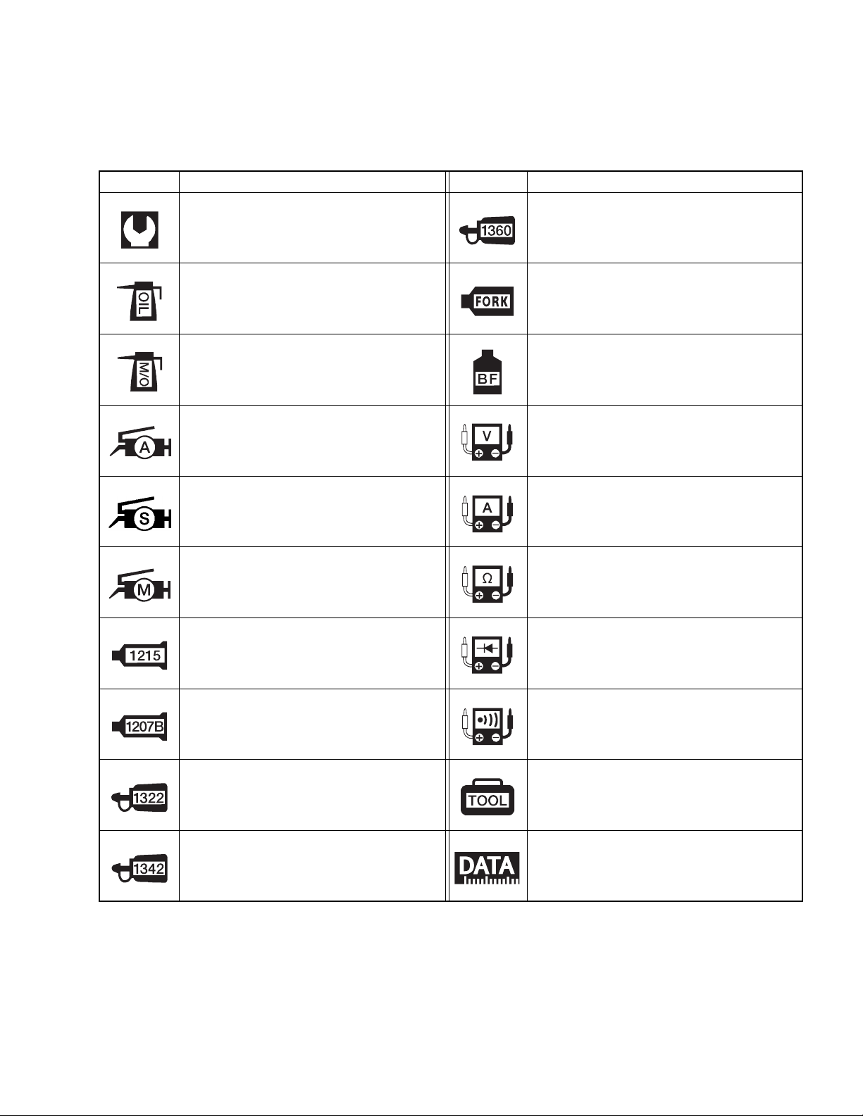
Listed in th e t able b elow ar e th e sy m bols i ndic ating ins truc tions a nd othe r in for matio n ne c essar y for ser vicing. The meaning of each symbol is also included in the table.
SYMBOL DEFINITION SYMBOL DEFINITION
Torqu e control requir ed.
Data beside it indicates specified
torque.
Apply oil. Use engine oil unless otherwise specified.
Apply molybdenum oil solution.
(Mixture of engine oil and SUZUKI
MOLY PASTE in a ratio of 1:1)
Apply SUZUKI SUPER GREASE “A”.
99000-25010
Apply SUZUKI SILICONE GREASE.
99000-25100
Apply SUZUKI MOLY PASTE.
99000-25140
Apply THREAD LOCK SUPER “1360”.
99000-32130
Use fork oil.
99000-99044-10G
Apply or use brake fluid.
Measure in voltage range.
Measure in current range.
Measure in resistance range.
Apply SUZUKI BOND “1215”.
99000-31110
Apply SUZUKI BOND “1207B”.
99000-31140
Apply THREAD LOCK SUPER “1322”.
99000-32110
Apply THREAD LOCK “1342”.
99000-32050
Measure in diode test range.
Measure in continuity test range.
Use special tool.
Indication of service data.
Page 4

White Page
http://www.motorcycle.in.th
Page 5
GENERAL INFO RMATION 1-1
http://www.motorcycle.in.th
GENERAL INFORMATION
CONTENTS
WARNING/CAUTION/NOTE.... ............... ............... .............. ............... ......... 1- 2
GENERAL PRECAUTIONS......................................................................... 1- 2
SUZUKI UY125K6/SK6 (’06-MODEL)......................................................... 1- 4
SERIAL NUMBER LOCATION................... .............. ............... ............... ..... 1- 4
FUEL AND OIL RECOMMENDATION ........................................................ 1- 5
FUEL.................... .............. ............... ............... .............. ............... ......... 1- 5
ENGINE OIL .......................................................................................... 1- 5
REDUCTION GEAR OIL ....................................................................... 1- 5
BRAKE FLUID (UY125S).. ............... ............... .............. ............... ......... 1- 5
FRONT FORK OIL................................................................................. 1- 5
BREAK-IN PROCEDURES.......................................................................... 1- 5
SPECIFICATIONS.................... ............... ............... .............. ............... ......... 1- 6
1
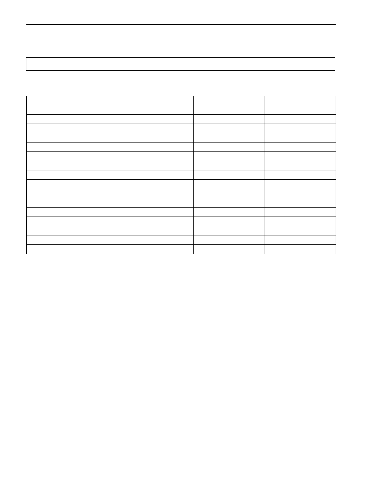
COUNTRY AND AREA CODES
The following codes stand for the applicable country(-ies) and area(-s).
CODE COUNTRY or AREA EFFECTIVE FRAME NO.
P-14 (UY125)
P-14 (UY125S)
Thailand
Thailand
CF48A-TH
CF48B-TH
!!!!!!
!!!!!!
–
–
Page 6

1-2 GENERAL INFORMATION
http://www.motorcycle.in.th
WARNING/CAUTION/NOTE
Please read thi s manua l and follow its instruc tions carefu lly. To em phasize s pecial info rmation, the symb ol
and the words WARNIN G, CA UTION and NOTE have speci al meanings . Pay sp ecial attent ion to the m essages highlighted by these signal words.
!
Indicates a potential hazard that could result in death or injury.
"
Indicates a potential hazard that could result in motorcycle damage.
NOTE:
Indicates special information to make maintenance easier or instructions clearer.
Please note , howev er, that the warnings and cauti ons contained in this manual c annot possibly cover all
potential h azards re lating to the servic ing, or lac k of servici ng, of th e motorc ycle. In ad dition to the WARN INGS and C AU TI ONS st ated , you mu s t use goo d judg em ent and bas ic mechanical sa fety p rinc iples . If you
are unsure about how to perform a particular service operation, ask a more experienced mechanic for
advice.
GENERAL PRECAUTIONS
!
* Proper service and repair procedures are important for the safety of the service mechanic and
the safety and reliability of the motorcycle.
* When 2 or more persons work together, pay attention to the safety of each other.
* When it is necessary to run the engine indoors , make sure that exhaust gas is fo rced out-
doors.
* When workin g w ith to xic o r flam ma ble m aterial s, m ak e s ure that the area you wo rk in is well-
ventilated and that you follow all of the material manufacturer’s instructions.
* Never use gasoline as a cleaning solven t.
* To avoid getting burned, do not touch the engine, engine oil, radiato r and exhaust system
until they have cooled.
After servicing the fuel, oil, water, exhaust or brake systems, check all lines and fittings related
to the system for leaks.
Page 7
GENERAL INFO RMATION 1-3
http://www.motorcycle.in.th
"
* If parts replacement is necessary, replace the parts with Suzuki Genuine Parts or their equiva-
lent.
* When removin g pa rts th at are t o be reused , k eep t hem a rrang ed in an orderl y man n er so that
they may be reinstalled in the proper order and orientation.
* Be sure to use special tools when instructed.
* Make sure th at all parts used in reassembly are clean. Lubricate them when specified.
* Use the specified lubricant, bond, or sealant.
* When removing the battery, disconnect the negative cable first and then the positive cable.
* When recon necting the b attery, conn ect the posi tive cable first and then the negative ca ble,
and replace the terminal cover on the positive terminal.
* When performing service to electrical parts, if the service procedures do not require use of
battery power, disconnect the negative cable from the battery.
* When tightening the cylinder head or case bolts and nuts, tighten the larger sizes first.
Always tighten the bolts and nuts diagonally from the inside toward outside and to the speci-
fied tightening torque.
* Whenever you remove oil seals, gaskets, packing, O-rings, locking washers, self-locking
nuts, cotter p ins, circlips and certain other pa rts as specified, be sure to repl ace them with
new ones. Als o, before installing these new parts, be sure to remove an y left over material
from the mating surfaces.
* Never reuse a circlip. When installing a new circlip, take care not to expand the end gap larger
than required to slip the circlip over the shaft. After installing a circlip, always ensure that it is
completely seated in its g roove and securely fitted.
* Use a torque wrench to tight en fast eners to t he spec ified torq ue. W ipe off g rease a nd oil if a
thread is smeared with them.
* After reassembling, check parts for tightness and proper operation.
* To protect the environment, do not unlawfully dispose of used motor oil and other fluids: bat-
teries and tires.
* To protect Earth’s natural resources, properly dispose of used motorcycle and parts.
Page 8
1-4 GENERAL INFORMATION
http://www.motorcycle.in.th
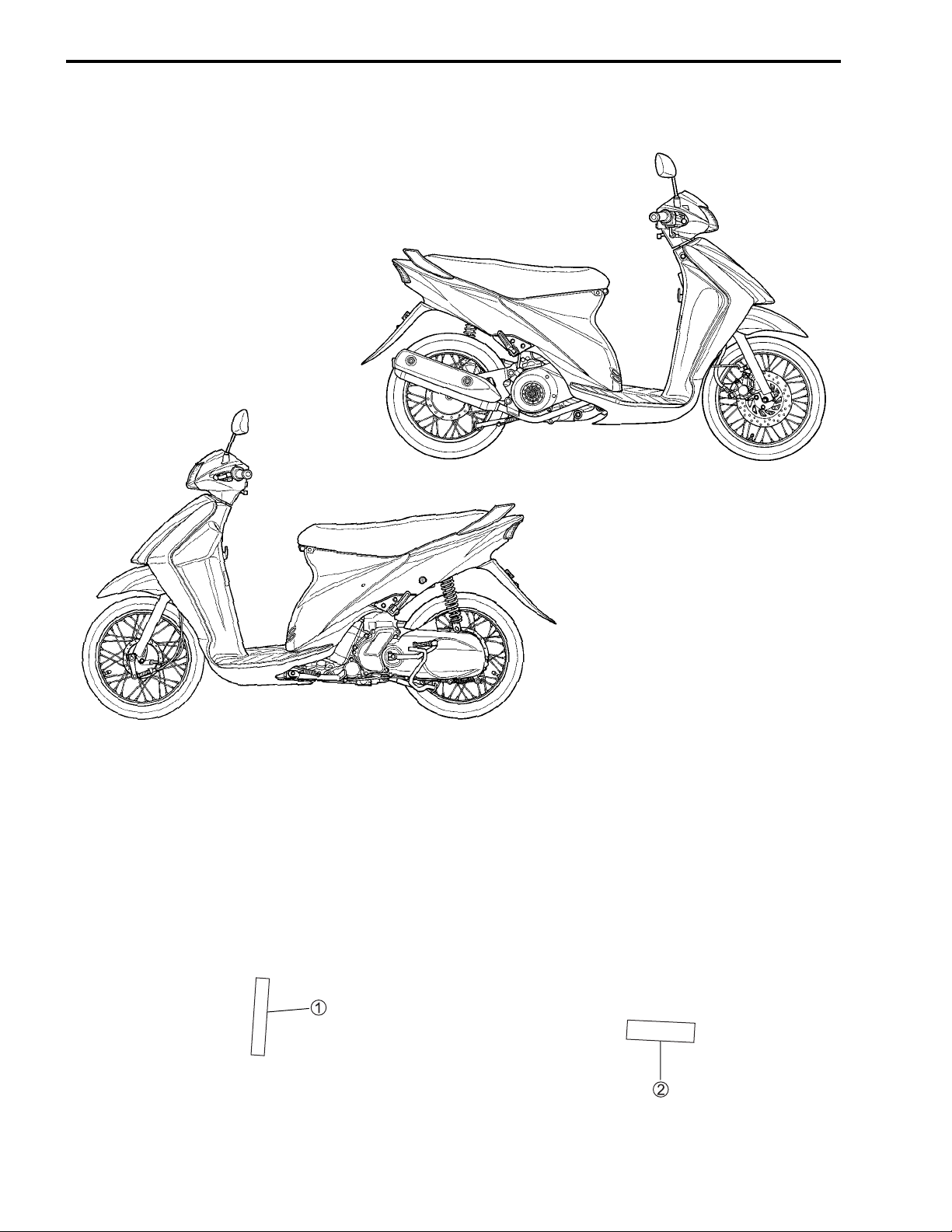
SUZUKI UY125K6/SK 6 (’06-M OD EL)
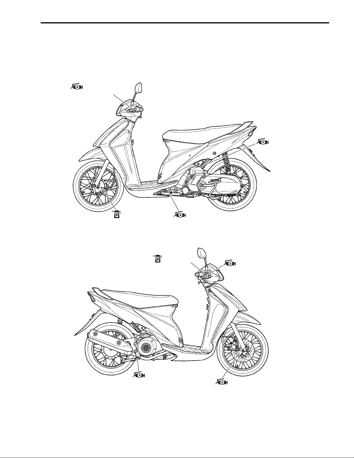
RIGHT SIDE (UY125S)
LEFT SIDE (UY125)
SERIAL NUMBER LOCATION
The frame s erial number or V.I.N. (Vehicle Identification Number) 1 is stamped on the left si de of the steering head pipe. The engine serial number 2 is loc ated on the left s ide of the crankc ase . The se num ber s are
required especially for registering the machine and ordering spare parts.
Page 9
GENERAL INFO RMATION 1-5
http://www.motorcycle.in.th
FUEL AND OIL RECOMMENDATION
FUEL
Gasoline used should be graded 91 octane (Research Method) or higher. Unleaded gasoline is recommended.
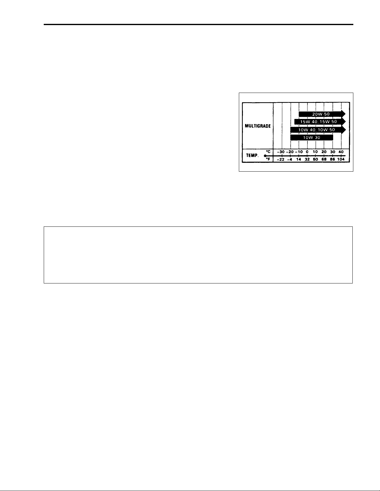
ENGINE OIL
Oil quality is a major contributor to your engine’s performance
and life . A lways sele ct g ood q uali ty e ngine o il. Us e o f SF/SG or
SH/SJ in API with MA in JASO.
Suzuki recommends the use of SAE 10W-40 engine oil. If SAE
10W-40 en gine oil is not ava ilable, sele ct an alternat ive acco rding to the right chart.
REDUCTION GEAR OIL
Use a good quality SAE 10W-40 multi-grade motor oil.
BRAKE FLUID (UY125S)
Specificat ion an d classifica tion : DOT 4
!
Since the brake system of this motorcycle is filled with a glyco l-based brake fluid by the manufacturer, do not use or mix different types of fluid such as silicone-based and petroleum-based
fluid for refilling the system, otherwise serious damage will result.
Do not use any brake fluid taken from old or used or unsealed containers.
Never re-use brake fluid left over from a previous se rvicing, which ha s been stored for a lo ng
period.
FRONT FOR K OIL
Use SUZUKI FORK OIL G10 (#10) or an equivalent fork oil.
BREAK-IN PROCEDURES
During m anu facture onl y th e be st po ssibl e mat erials a re used and all ma chined pa rts a re finis hed to a v ery
high standard but it is still necessary to allow the moving parts to “BREAK-IN” before subjecting the engine
to maximum stresses. The future performance and reliability of the engine depends on the care and restraint
exercised during its early life. Refer to the following throttle position recommendations.
• Keep to these break-in throttle positions:
Initial 800 km: Less than 1/2 throttle
Up to 1 600 km: Less than 3/4 throttle
• Upon reaching an odometer reading of 1 600 km you can subject the motorcycle to full throttle operation
for short periods of time.
Page 10

1-6 GENERAL INFORMATION
http://www.motorcycle.in.th
SPECIFICATIONS
DIMENSIONS AND DRY MASS
Overall length.......................................................................... 1 859 mm
Overall width........................................................................... 654 mm
Overall height .......................................................................... 1 046 mm
Wheelba se.............................................................................. 1 244 mm
Ground clearance ................................................................... 145 mm
Dry mass................................................................................. 94.2 kg .......... UY125
95.5 kg .......... UY125S
ENGINE
Type........................................................................................ Four stroke, forced air-cooled, OHC
Number of cylinders................................................................ 1
Bore ............................................ ............................................ 53.5 mm
Stroke...................................................................................... 55.2 mm
Displacement........................ .................................................. 124 cm³
Compression ratio................................................................... 9.6 : 1
Carburetor............................................................................... MIKUNI BS26
Air cleaner.......... ....... ............ ...... ....... ...... ...... ...... ...... ....... ...... Paper element
Starter system......................................................................... Electric and kick
Lubrication system...................... ....... ...... ...... ...... ...... ....... ...... Wet su mp
Idle speed............................................................................... 1 600 ± 100 rpm
TRANSMISSION
Clutch...................................................................................... Dry shoe, automatic, centrifugal type
Reductio n ratio........................................................................ Variable change (2.700 – 0.825)
Final reduction ratio ................................................................ 9.264 (49/17 × 45/14)
Drive system........................................................................... V-be lt drive
CHASSIS
Front suspension .................................................................... Teles copic, coil spring, oil damped
Rear suspension.................................................. ................... Swingarm type, coil spring, oil damped
Front fork stroke...................................................................... 85 mm
Rear wheel travel................................................. ................... 80 mm
Steering angle......................................................................... 45° (right and left)
Caster ..................................................................................... 25.6°
Trail......................................................................................... 100 mm
Turning radius......................................................................... 1.9 m
Front brake................................................................. ............. Drum brake.......... UY125
Disc brake............ UY125S
Rear brake .............................................................................. Drum brake
Front tire size.......................................................................... 70/90-14 M/C (34 P), tube type
Rear tire size........................................................................... 80/90-14 M/C (40 P), tube type
Page 11

GENERAL INFO RMATION 1-7
http://www.motorcycle.in.th
ELECTRICAL
Ignition t ype............................................................................. Electronic ignition (CDI)
Ignition t iming.......................................................................... 10° B.T.D.C.at 1 600 rpm
Spark plug ............. .................................................................. NGK CR6HSA or DENSO U20FSR-U
Battery..................................................................................... 12 V 12.6 k C (3.5 Ah)/10 HR
Generator................................................................................ Single-phase A.C. generator
Fuse ......... ....... ...... ...... ...... ....... ...... ...... ............ ....... ...... ...... .... 10 A
Headlight........................................ ......................................... 12 V 30/30 W
Turn signal light.................................... ................................... 12 V 10 W
Brake light/T aillight............................... ...... ...... ....... ...... ...... .... 12 V 18/5 W
Speedometer light................................................................... 12 V 3.4 W
High beam indicator light......................................................... 12 V 1.7 W
Turn signal indicator light ........................................................ 12 V 1.7 W
CAPACITIES
Fuel tank ................................................................................. 3.7 L
Engine oil, oil change ............................................................. 950 ml
with filter change................................................... 1 050 ml
overhaul................................................................ 1 100 ml
Reductio n gear oil, oil change................................................ 100 ml
overhaul .................................................. 110 ml
These specifications are subject to change without notice.
Page 12

White Page
http://www.motorcycle.in.th
Page 13

PERIODIC MAINTENANCE 2-1
http://www.motorcycle.in.th
PERIODIC MAINTENANCE
CONTENTS
PERIODIC MAINTENANCE SCHEDULE ................ ... .......................... ......... 2- 2
PERIODIC MAINTENANCE CHART .......... .......................... .............. .. 2- 2
LUBRICATION POINTS ....... ............... .............. ............... ............... ..... 2- 3
MAINTENANCE AND TUNE-UP PROCEDURES ......................................... 2- 4
AIR CLEANER ...................................................................................... 2- 4
EXHAUST PIPE BOLT AND MUFFLER MOUNTING NUT ................. 2- 5
COOLING FAN FILTER ....................................................................... 2- 5
VALVE CLEARANCE ........................................................................... 2- 6
SPARK PLUG ..... .............. ............... ............... .............. ............... ......... 2- 7
FUEL LINE ............................................................................................ 2- 8
ENGINE OIL AND OIL FILTER ............................................................ 2- 8
ENGINE IDLE SPEED .......................................................................... 2-10
THROTTLE CABLE PLAY ................................................................... 2-10
DRIVE BELT ......................................................................................... 2-11
REDUCTION GEAR BOX OIL .............................................................. 2-11
BRAKE ................................................................................................. 2-12
BRAKE HOSE AND BRAKE FLUID (UY125S) ................................... 2-13
TIRE AND WHEELS .......................................... ............... ............... ..... 2-15
STEERING ............................................................................................ 2 -17
FRONT FORK ....................................................................................... 2-17
REAR SUSPENSION ........................................................................... 2-17
CHASSIS BOLTS AND NUTS .............................. .......................... ..... 2-18
COMPRESSION PRESSURE CHECK ........................... .......................... ..... 2-20
COMPRESSION TEST PROCEDURE ............................. .................... 2-20
OIL PRESSURE CHECK ...................... ............... ............... .............. ............. 2-21
OIL PRESSURE TEST PROCEDURE ................................................. 2-21
AUTOMATIC CLUTCH INSPECTION ............................ ............... .............. .. 2-22
1. INITIAL ENGAGEMENT INSPECTION ............................................ 2-22
2. CLUTCH “LOCK-UP” INSPECTION ............................................... 2-22
2
6
Page 14
2-2 PERIODIC MAINTENANCE
http://www.motorcycle.in.th
PERIODIC MAINTENANCE SCHEDULE
The chart below lists the recommended intervals for all the required periodic service work necessary to keep
the motorcycle operating at peak performance and economy. Mileages are expressed in terms of kilometer
and time for your convenience.
NOTE:
More frequent servicing may be performed on motorcycles that are used under severe conditions.
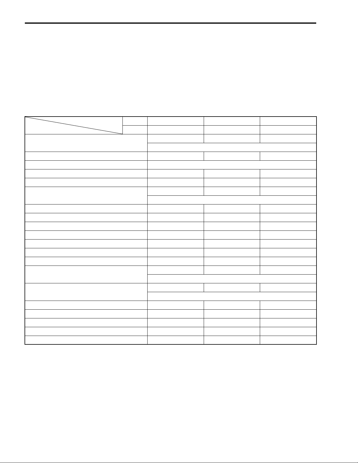
PERIODIC MAINTENANCE CHART
Interval
Item
Air cleaner
Exhaust pipe bolt and muffler bolt T — T
Cooling fan filter Clean every 3 000 km.
Valve clearance I I I
Spark plug — I R
Fuel line
Engine oil R R R
Engine oil filter R — R
Idle rpm I I I
Throttle cable play I I I
Drive belt — I I
Final reduction gear box oil — — I
Brake I I I
Brake hose (UY125S)
Brake fluid (UY125S)
Tire and wheels — I I
Steering I — I
Front fork — — I
Rear suspension — — I
Chassis bolt and nut T T T
km 1 000 4 000 8 000
months 5 20 40
—I I
Replace every 12 000 km.
—I I
Replace every four years.
—I I
Replace every four years.
—I I
Replace every two years.
NOTE:
I = Inspect and adjust, clean, lubricate or replace as necessary
R = Replace
T = Tighten
Page 15
PERIODIC MAINTENANCE 2-3
http://www.motorcycle.in.th
LUBRICATION POINTS
Proper lubrication is important for smooth operation and long life of each working part of the motorcycle.
Major lubrication points are indicated below.
Rear brake
lever holder
Footrest pivot
Speedometer
cable
Center stand pivot
and spring hook
Side-stand pivot
and spring hook
Throttle cable
Front brake
lever holder
Speedometer
gearbox
NOTE:
* Before lubricating each part, clean off any rusty spots and wipe off any grease, oil, dirt or grime.
* Lubricate exposed parts which are subject to rust, with a rust preventative spray whenever the motorcycle
has been operated under wet or rainy conditions.
Page 16
2-4 PERIODIC MAINTENANCE
http://www.motorcycle.in.th
MAINTENANCE AND TUNE-UP
PROCEDURES
This section describes the servicing procedures for each item of
the Periodic Maintenance requirements.
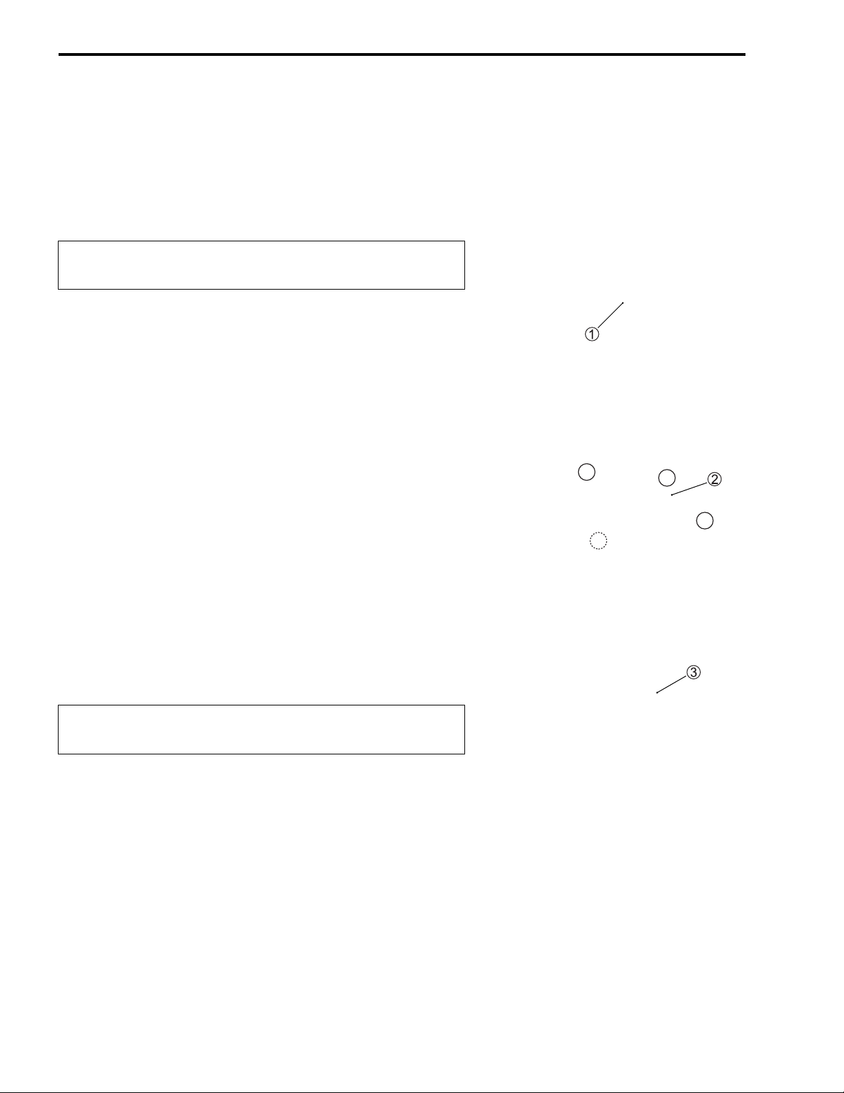
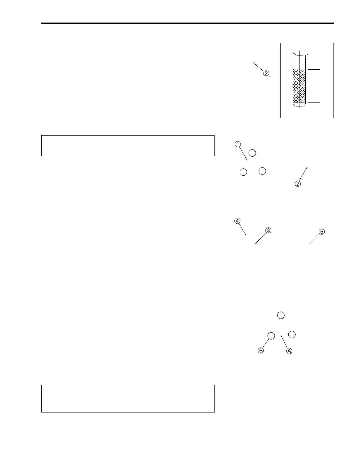
AIR CLEANER
Inspect every 4 000 km (20 m ont hs) and rep lac e every
12 000 km thereafter.
• Place the motorcycle on the side stand.
• Remove the frame cover (left and right). (!5-10)
• Remove the hook 1.
• Remove the air cl eaner element bo x cap 2 b y removing th e
screws.
• Remove the air cleaner element 3.
• Inspect the air cleaner element for clogging.
If the a ir cleaner eleme nt is clo gge d wi th dust, r eplace th e a ir
cleaner element with a new one.
"
Do not blow the a ir cleaner el ement with com pressed
air.
NOTE:
If driving u nder dusty conditions, replace the air cleaner element
more frequently. Make sure that the air cleaner is in good condition at all times. The l ife of the e ngine depends largely on thi s
component.
• Install a new air cleaner element in the reverse order of
removal.
Page 17
• Remove the drain plug from the air cl eaner box to allow any
http://www.motorcycle.in.th
water to drain out.
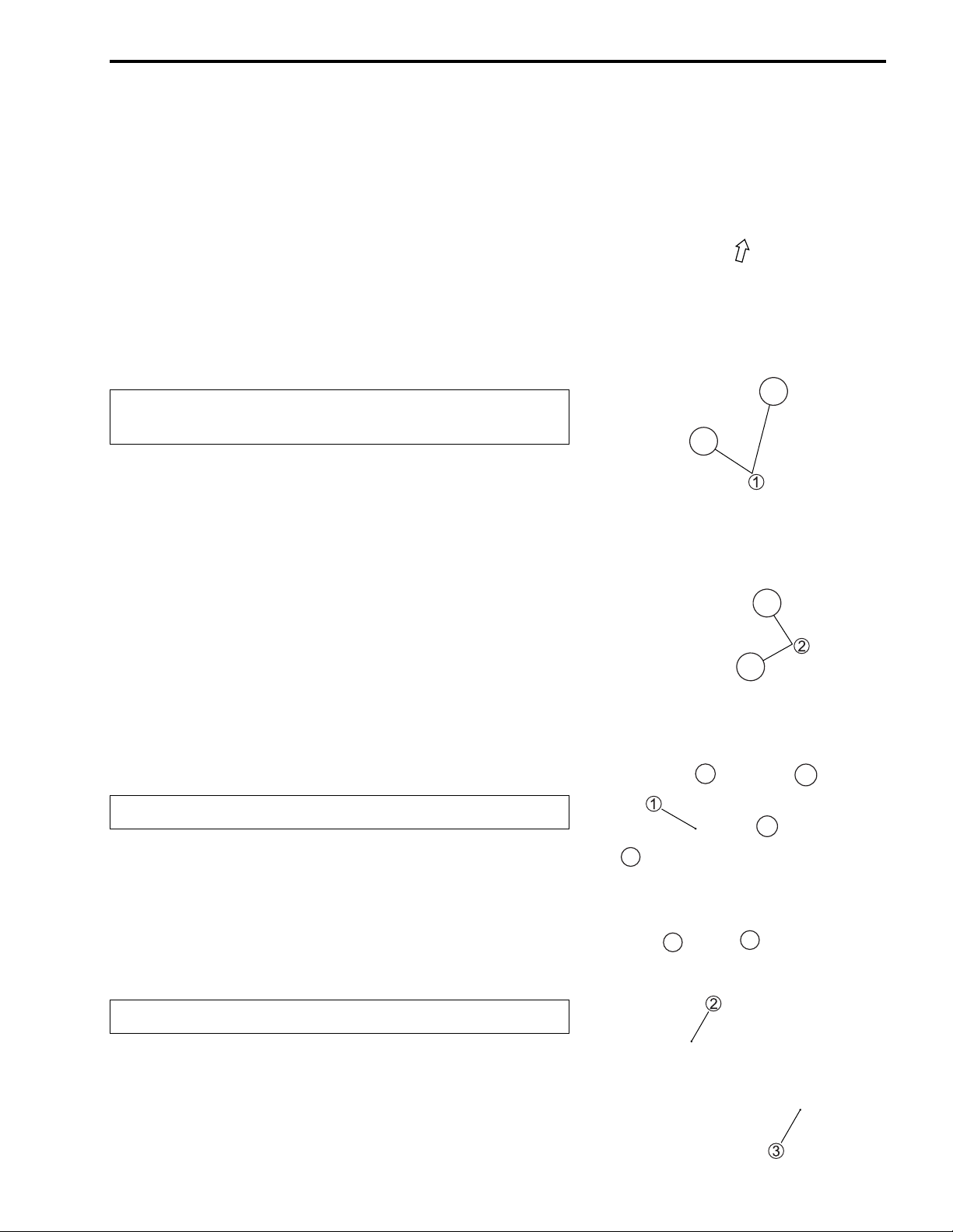
EXHAUST PIPE BOLT AND MUFFLER
MOUNTING NUT
Tighten initially at 1 000 km (5 m onths) and every
8 000 km (40 months) thereafter.
• Tighten th e exhaust pipe bolts 1 and muffler mounting bolts
2.
PERIODIC MAINTENANCE 2-5
COOLING FAN FILTER
Clean every 3 000 km.
• Remove the cooling fan cover 1.
• Remove the holder 2 and cooling fan filter 3.
• Clean th e fa n f ilter in the s am e man ner o f th e a ir cl ea ner el ement.
• Reinstall the cleaned or new filter in the reverse order of
removal.
"
Do not apply engine oil to the filter after cleaning it.
Page 18
2-6 PERIODIC MAINTENANCE
http://www.motorcycle.in.th
VALVE CLEARANCE
Inspect initially at 1 000 km (5 months) and every
4 000 km (20 month s) thereafter.
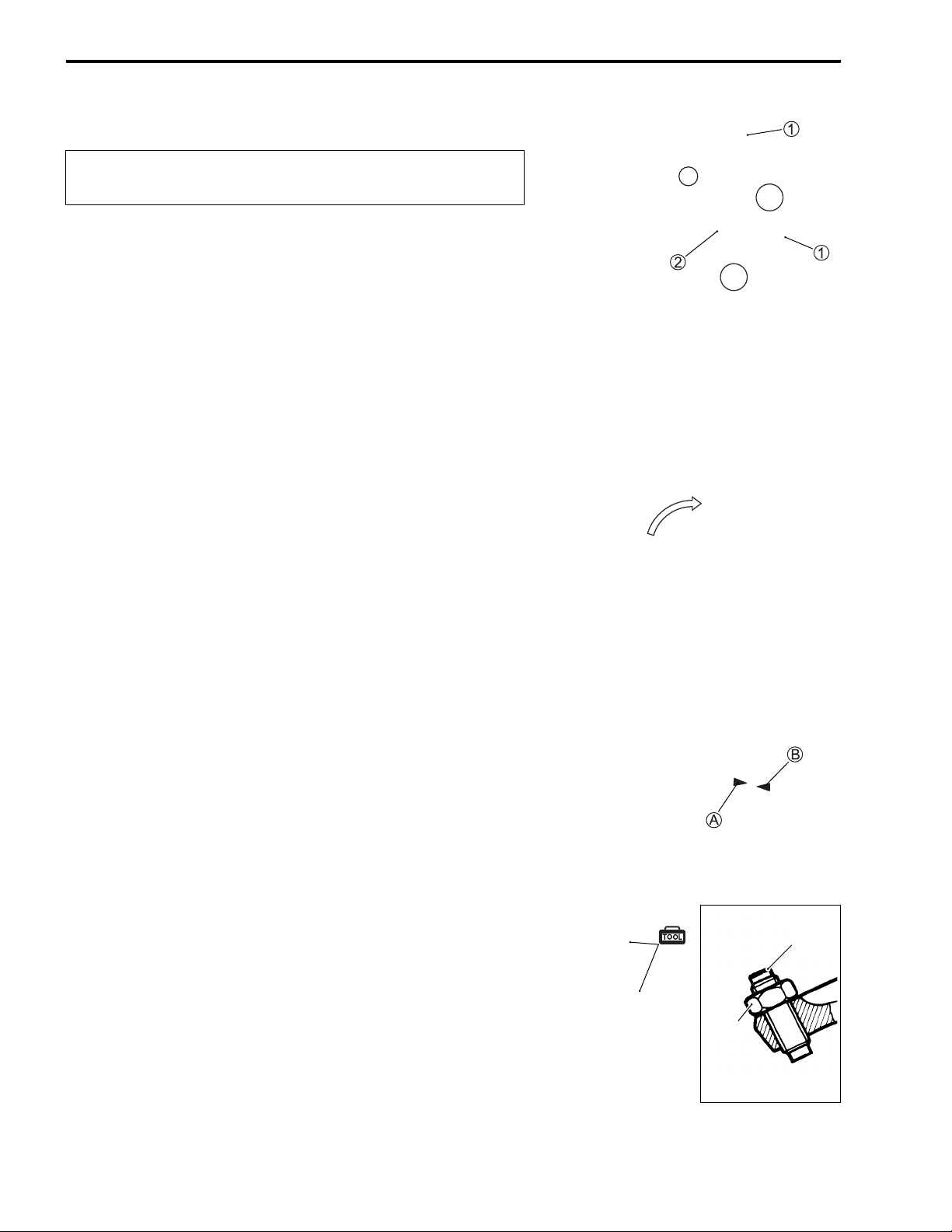
REMOVAL
• Remove the frame front cover. (!5-8)
• Remove the spark plug. (!2-7)
• Disconnect the breather hoses 1 and remove the head cover
2.
INSPECTION
The valve clearance specification is s ame for both valves. Valve
clearance adjustment must be checked and adjust ed, 1) at the
time of periodic inspection, 2) when the valve mechanism is serviced, and 3) wh en the camshaft is distur bed by removin g it for
servicing.
NOTE:
* The piston must be at (TDC) on the compression stroke in
order to check the valve clearance or to adjust valve clear-
ance.
* The clearance specification is for COLD state.
* To turn the crankshaft for clearance checking, rotate in the nor-
mal running direction. The spark plug should be removed.
• Turn crankshaft to brin g the “TD C” mark A on the cooling fan
to the index mark B on the crankcase.
• Insert a thickness gau ge betw ee n the valve stem end and the
adjusting screw on the rocker arm.
If the clear ance is out of specifi cation, bring i t into the spe cified range.
# Valve clearance (when cold):
IN.: 0.04 – 0.07 mm
EX.: 0.10 – 0.15 mm
$ 09900-20803: Thickness gauge
09917-13210: Valve adjusting driver
Adjuster
Lock-nut
Page 19

• After finishing the valve clearance adjustment, reinstall the fol-
http://www.motorcycle.in.th
lowing items.
* Cylinder head cover (!3-11)
* Spark plug and plug cap (!2-7)
* Frame front cover (!5-8)
SPARK PLUG
Inspect at 4 000 km (20 months) and replace every
8 000 km (40 months) thereafter.
REMOVAL
• Remove the frame front cover. (!5-8)
• Disconnect the spark plug cap and remove the spark plug.
PERIODIC MAINTENANCE 2-7
$ 09930-10121: Spark plug socket wrench set
Standard
NGK CR6HSA
DENSO U20FSR-U
CARBON DEPOSIT
Check to see the carbon deposit on the plug.
If the carbon is deposite d, remove it with a spark plug cle aner
machine or carefully using a tool with a pointed end.
SPARK PLUG GAP
Measure th e plug gap with a thickness gauge if it is correct. If
not, adjust it to the following gap.
# Spark plug gap:
Standard: 0.6 – 0.7 mm
$ 09900-20803: Thickness gauge
ELECTRODE’S CONDITION
Check to see the worn or burnt condition of the electrodes. If it is
extremely worn or burnt, r eplace the plug . And als o repl ace the
plug if it has a broken insulator, damage d thread, etc.
"
Confirm the thread s ize and reac h when re placing the
plug. If the r eac h is too s hort , carb on wil l be depo sit ed
on the screw portion of the plug hole and engine damage may result.
0.6 – 0.7 mm
Page 20
2-8 PERIODIC MAINTENANCE
http://www.motorcycle.in.th
INSTALLATION
"
Before using a spark plug wren ch, carefully turn the
spark plug by finger into the threads of the cylinder
head to prevent damage the aluminum threads.
• Install the spa rk pl ug to the cylinde r hea d by finge r tight, and
then tighten it to the specified torque.
% Spark plug: 11 N·m (1.1 kgf-m)
$ 09930-10121: Spark plug wrench set
FUEL LINE
Inspect every 4 000 km (20 months) thereafter.
Replace every 4 years.
Inspect the fuel hoses for damage and fuel leakage. If any
defects a re found, the fuel hoses must be replaced.
ENGINE OIL AND OIL FILTER
ENGINE OIL REPL ACEMENT
Replace initially at 1 000 km (5 months) and every
4 000 km (20 months) thereafter.
• Ke ep the motorcycle upright.
• Place an oil pan bel ow the engine. Drain oil by rem oving the
engine oil drain plug 1.
• Remove the oil filler cap 2.
• Tighten the engine oil drain plug 1 to the specified torque.
Pour new oil through the oil filler hole. When performing an oil
change (without oil filter replacement), the engine will hold
about 950 ml of oil. Us e an eng ine oil tha t meets AP I service
classifications SF or SG and that has a viscosity rating of SAE
10W-40.
% Engine oil drain plug 1: 18 N·m (1.8 kgf-m)
• Make sure that the engine is cooled.
• Place the motorcycle on level ground and hold it vertically.
• Install the oil filler cap 2.
• Start the engine and allow it to run for a few minu tes at idling
speed.
Page 21
• Turn off the en gine and wait minute, then check the oil level
http://www.motorcycle.in.th
by removing the filler cap 2. If the level is below mark “L”,
add oil to “F” level. (off the center stand, do not screw the filler
cap.)
If the level is above mark “F”, drain oil to “F” level.
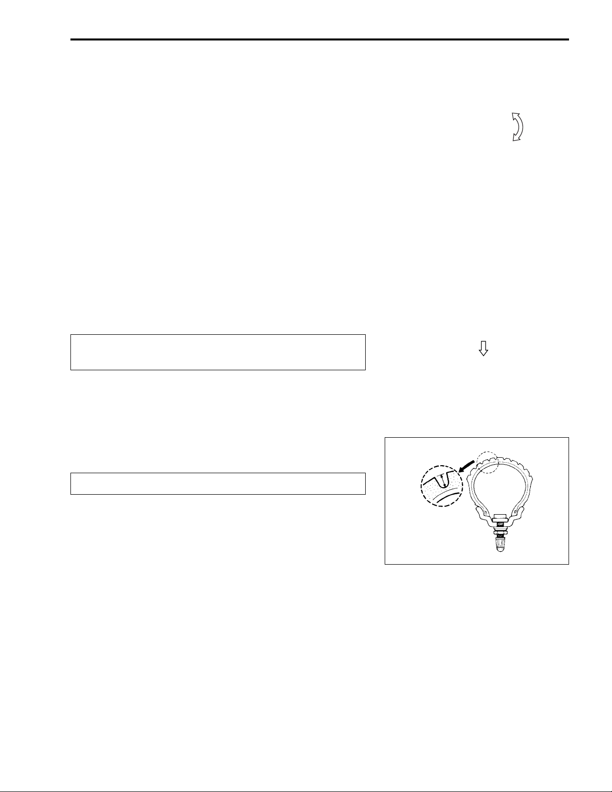
OIL FILTER REPLACEMENT
Replace initially at 1 000 km (5 months) and every
8 000 km (40 months) thereafter.
• Drain engine oil as described in the engine oil replacement
procedure.
• Remove the oil filter cap 1 and oil filter 2.
• Replace the oil filter with a new one.
PERIODIC MAINTENANCE 2-9
F
L
• Install the spring 3 correctly.
• Apply engine oil lightly to the O-rings 4 and 5.
• Install the oil filter cap and tighten the bolts securely.
% Oil filter ca p bolt: 10 N·m (1.0 kgf-m)
NOTE:
* Before instal ling the new oil filter a nd oil filte r cap, make sure
that the spring 3 and new O-rings 4, 5 are installed correctly.
* The arrow mark A on the oil filter cap should be positione d
down.
* Fit the clamp to the bolt B.
• Add new engine oil and c heck the oil level as described in the
engine oil replacement procedure.
# Oil viscosity and classification:
10W-40 (SAE)/SF or SG (API)
# NECESSARY AMOUNT OF ENGIN E OIL
Oil change : 950 ml
Oil and filter change : 1 050 ml
Engine overhaul : 1 100 ml
"
Make sure t hat the o il filter i s install ed prop erly. If th e
filter is installed improperly, serious engine damage
may result.
OIL SUMP FILTER CLEANING (!3-19 and -57)
Page 22
2-10 PERIODIC MAINTENANCE
http://www.motorcycle.in.th
ENGINE IDLE SPEED
Inspect initially at 1 000 km (5 months) and every
4 000 km (20 month s) thereafter.
NOTE:
Make this adjustment when the engine is hot.
• Connect an electric tachometer.
• Start up the en gine and set its sp eed at anywhere between
1 500 and 1 700 rpm by turning throttle stop screw.
Engine idle speed: 1 600 ± 100 rpm
$ 09900-26006: Tachometer
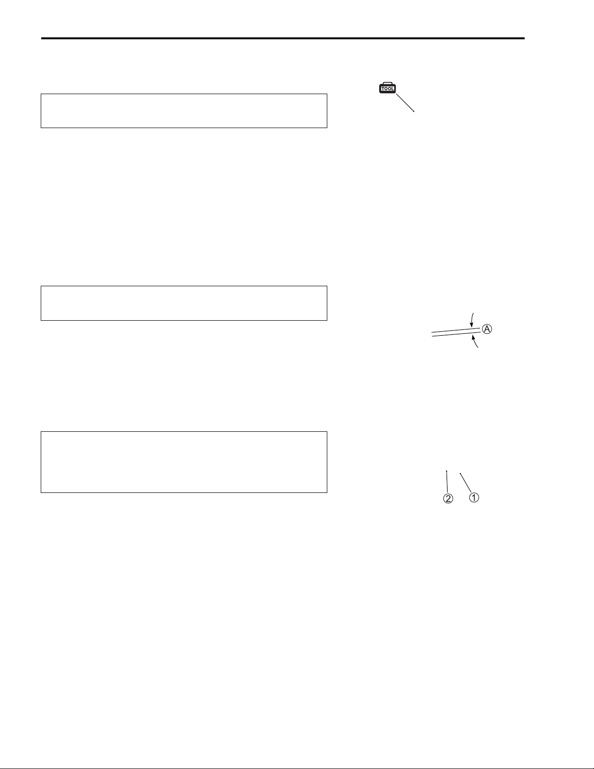
THROTTLE CABLE PLAY
Inspect initially at 1 000 km (5 months) and every
4 000 km (20 month s) thereafter.
Adjust the throttle cable play A with the following proced ure s.
• Loosen the l ock-nut 1 of the throttle cable.
• Turn the adjus ter 2 in or out until the throttle cable play A
should b e 2.0 – 4.0 mm at the throttle grip.
• Tighten the lock-nut 1 while holding the adjuster 2.
Throttle cable play A: 2.0 – 4.0 mm
&
After the a djustmen t is co mpleted , chec k that h andlebar movement does not raise the engine idle speed
and that the throttle grip returns smoothly and automatically.
NOTE:
Major adjus tment can be made by the carburetor side adjuster.
Page 23
DRIVE BELT
http://www.motorcycle.in.th
Inspect every 4 000 km (20 months) thereafter.
• Keep the motorcycle upright.
• Remove the clutch cover. (!3-10)
• Check the c on tact sur face f or cr ack or othe r d ama ge. If crack
or other damage exists, replace the b elt with a new one.
"
If grease or oil is p rese nt on the surfa ce, d ec reas e the
belt thoroughly.
• Install the clutch cover. (!3-72)
NOTE:
Drain water from the clutch cover by removing the drain bolt A.
PERIODIC MAINTENANCE 2-11
REDUCTION GEAR BOX OIL
Inspect every 8 000 km (40 months) thereafter.
• Keep the motorcycle upright.
• Place an oil pan bel ow the ge ar case , and drain oil by r emo ving the oil drain plug 1 and fil ler cap 2.
• Tighten the drain plug 1, and pour fresh oil through the o il
filler.
Oil viscosity and classific ation: SAE 10 W-40 with SF or SG
NECESSARY AMOUNT OF REDUCTION GEAR OIL
Oil change: 100 ml
Overhaul: 110 ml
Page 24
2-12 PERIODIC MAINTENANCE
http://www.motorcycle.in.th
BRAKE
Inspect initially at 1 000 km (5 months) and every
4 000 km (20 month s) thereafter.
BRAKE LEVER PLAY
• Adjust the brake lever play by turning the adjusting nut 1 so
that the play A is 15 – 25 mm as shown.
# Brake lever play A: 15 – 25 mm
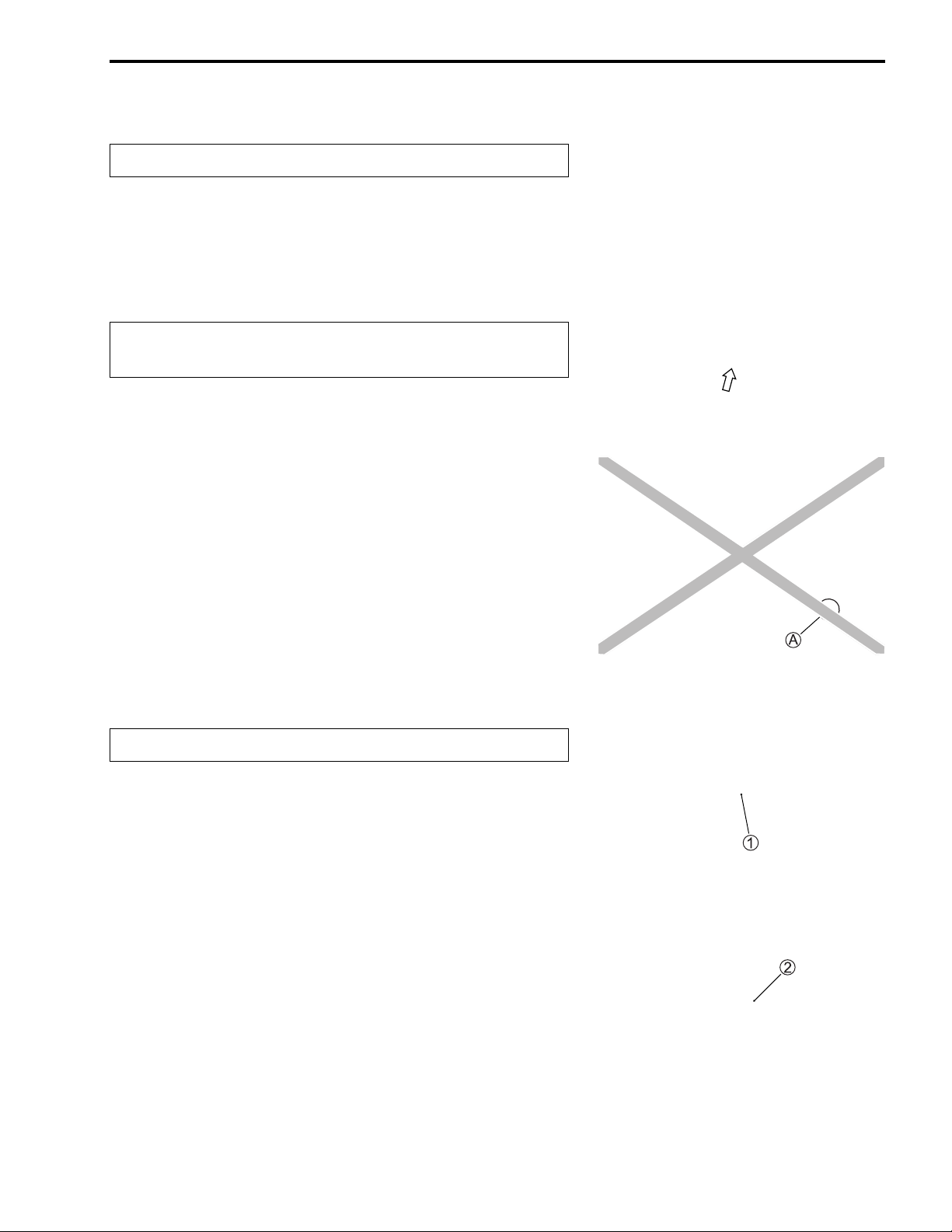
FRONT BRAKE PADS (UY125S)
The extent o f brake pad wear can be checke d by obse rving the
grooved limit line A on the brake pad . When t he wear ex ceeds
the grooved limit line, replace the pads with new ones.
(!5-25)
"
Replace the brake pads as a set, otherwise braking
performance will be adversely affected.
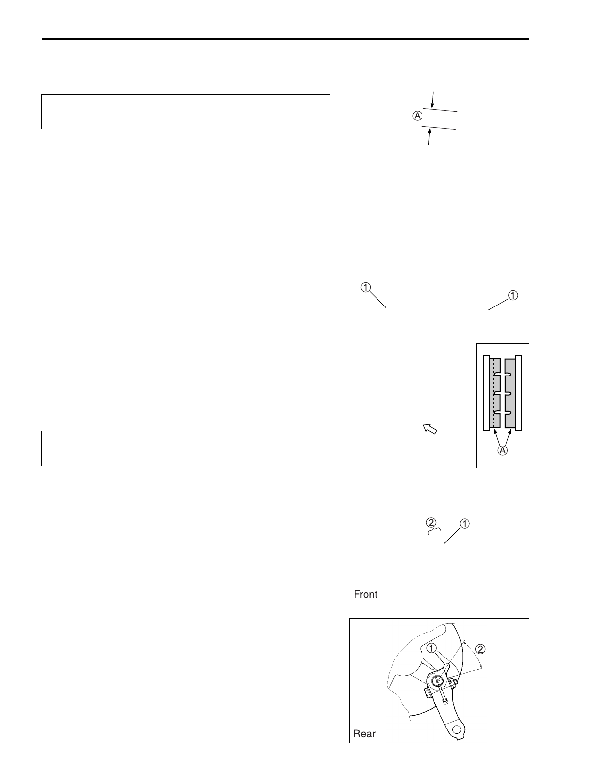
BRAKE SHOW WEAR
This motorcycle is equipped with the brake lining wear limit indicator on the brake.
To check wear of the brake lining, perform the following steps:
• First, check if the brake system is properly adjusted.
• While operating the brake, check to see tha t the tip of indic ator 1 is within the range 2 on the brake panel.
• If the tip of indicator 1 is beyond the ran ge, the brake shoe
assembly should be replaced with a new set of shoe.
(!5-13 and -49)
Page 25
BRAKE HOSE AND BRAKE FLUID (UY125S)
http://www.motorcycle.in.th
Inspect every 4 000 km (20 months).
Replace hoses every 4 years. Replace fluid every 2
years.
BRAKE HOSE
Check the brake hose for leakage, cracks, wear and damage. If
any damages are found, replace the brake hose with a new one.
PERIODIC MAINTENANCE 2-13
BRAKE FLUID LEVEL CHECK
• Keep the motorcycle upright and place the handlebars
straight.
• Check the brake flu id level relativ e to the low er limit li nes on
the front brake fluid reservoirs.
• When the level is below the lower limit line, replenish with
brake fluid that meets the following specification.
' Specification and classification: DOT 4
&
* The brake sys tem of this motorcyc le is filled with a
glycol-based brake fluid. Do not use or mix different
types of fluid such as silicone-based and petroleum-based fluids. Do not use any brake fluid taken
from old, used or unsealed containers. Never re-use
brake fluid left over from the last servicing or stored
for a long period of time.
* Brake fluid, if it leaks, will int erfere with safe runn ing
and immediately discolor painted surfaces. Check
the brake ho ses and h ose joi nts for crac ks and f luid
leakage before riding.
Page 26

2-14 PERIODIC MAINTENANCE
http://www.motorcycle.in.th
FRONT BRAKE FLUID REPLACEMENT
• Remove the handlebar cover . (!5-5)
• Place the motorcycle on a level surface and keep the handlebar st ra ig h t.
• Remove the front master cylinder reservoir cap and diaphragm.
• Suck up the old brake fluid as much as possible.
• Fill the reservoir with new brake fluid.
' Specification and classification: DOT 4
• Connect a clear hose 1 to the air bleeder valve and insert the
other end of the hose into a receptacle.
• Loosen the a ir bleeder valve and pump the brake lever unt il
the old brake fluid is compl etely out of the brake system.
• Close the air bleeder valve and disconnect the clear hose. Fill
the reservoir with new brake fluid to the upper end of the
inspection window.
% Air bleeder valve: 7.5 N·m (0.75 kgf-m)
AIR BLEEDING FOR THE FRONT BRAKE FLUID CIRCUIT
Air trapped in the fluid circuit acts like a cushion to absorb a
large proport ion of the pressu re developed by the master cylinder and thus inte rferes with the full brak ing performance of th e
brake calipe r. The presence of air is indicated b y “sponginess”
of the brake lever and also by lack of brak ing for ce. Con s iderin g
the dange r to whic h such trapped a ir exp oses the m achine and
rider, it is es sential that , after remou nting the br ake and resto ring the brake system to the normal condition, the brake fluid circuit be purged of air in the following manner:
• Fill up the master cylinder reservoir to the “UPPER” line.
Place the reservoir cap to prevent entry of dirt.
• Connect a clear hos e 1 to the air bleeder valv e, and insert
the free end of the pipe into a receptacle.
• Front brake: Bleed the air from the air bleeder valve.
Page 27
• Squeeze an d release the brake lever sever al times in rapid
http://www.motorcycle.in.th
succession and squeeze the lever fully without releasing it.
Loosen the bleeder valve by turning it a quar ter of a turn so
that the brake fluid runs into the receptac le; this will remove
the tension o f the brake l ever causing it to touch th e handlebar grip. Th en, close th e valve, pu mp and s queeze the lever,
and open the valve.
Repeat this pr ocess unti l the fluid flow ing into the recepta cle no
longer contains air bubbles.
NOTE:
Replenish the brake fluid in the reservoir as necessary while
bleeding the brake system. Make sure that there is alw ays some
fluid visible in the reservoir.
• Close the bleeder valve, and disconnect the clear hos e.
% Air bleeder valve: 7.5 N·m (0.75 kgf-m)
Fill the reservoir with brake fluid to the “UPPER” line.
PERIODIC MAINTENANCE 2-15
"
Handle brake fluid with care: the fluid reacts chemically with paint, plastics, rubber materials and so on.
TIRE AND WHEELS
TIRE TREAD CONDITION
Inspect every 4 000 km (20 months).
Operating the motorcycle with excessively worn tires will
decrease riding stability and consequently invite a dangerous
situation. It is highly recommended to replace a tire when the
remaining depth of the tire tread reaches the following specification.
$ 09900-20805: Tire depth gauge
# Tire tread depth:
Service Limit: FRONT:1.6 mm
R EAR: 1.6 mm
Page 28
2-16 PERIODIC MAINTENANCE
http://www.motorcycle.in.th
TIRE PRESSURE
If the tire pressure is too high or too low, steering will be
adversely aff ected and tire we ar will incre ase. Therefore , maintain the correct tire pressure for good ro adability and a longer
tire life. Co ld inflation tire pressure is as follows.
COLD INFLATION
TIRE PRESSURE
kPa kgf/cm
2
FRONT 175 1.75
REAR 225 2.25
"
The standard tire fitted on this motorcycle is a 70/
90-14M/C 34 P for the front and a 80/90-14M/C 4 0P for
the rear. The use of tires other than those specified
may cause instability. It is highly r ecommended to use
the specified tires.
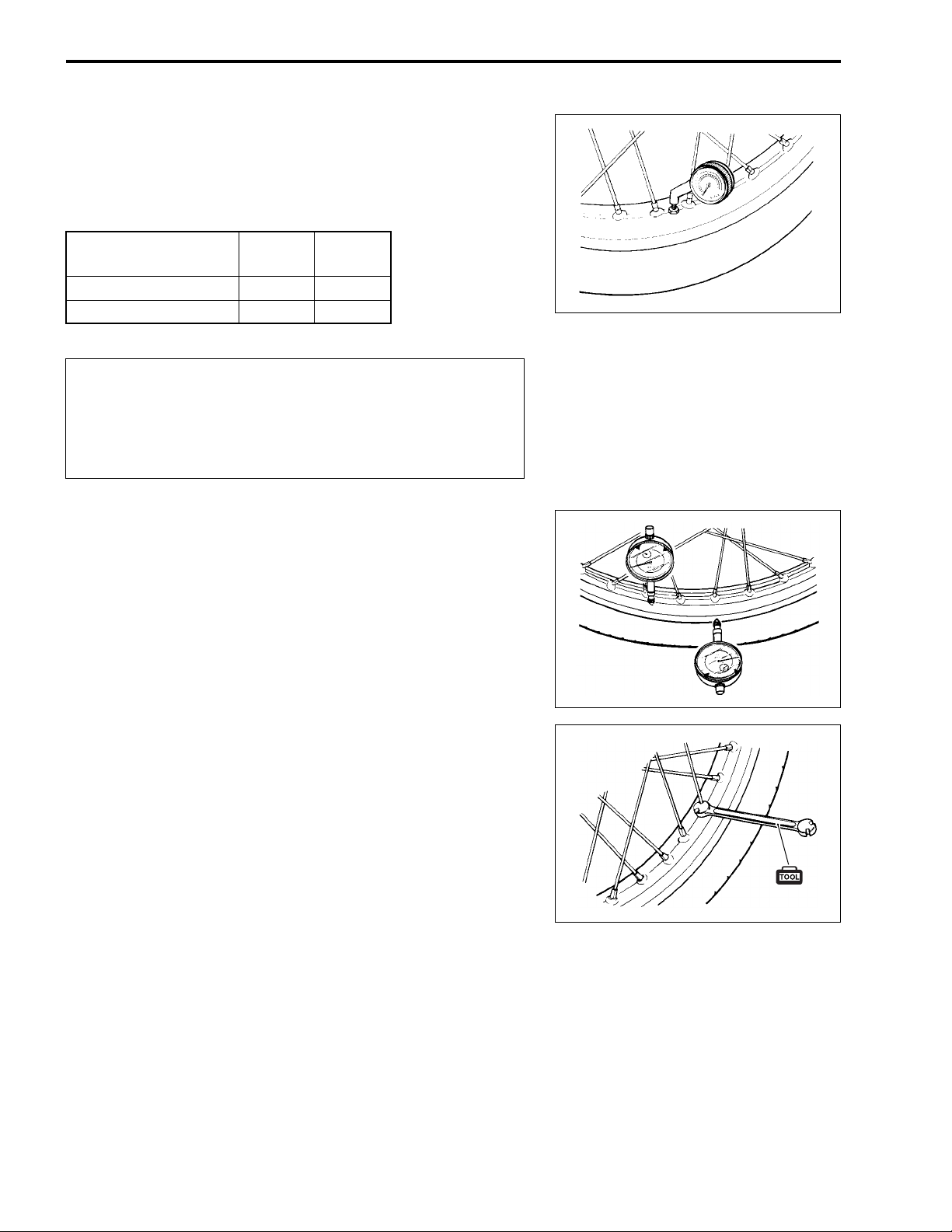
WHEEL
Make sure that the wheel runout (axial and radial) does not
exceed the service limit when checked as shown. An excessive
amount of runout is usually due to worn or loose wheel bearings
and can be corrected by replacing the bearings. If bearing
replacement fails to reduce the runout, replace the wheel.
# Wheel runout
Service Limit (axial and radial): 2.0 mm
SPOKE NIPPLES
Make sure t hat the nippl es are tight . If necess ary, tighten them
with a spoke nipple wrench.
% Spoke nipple: 4.5 N·m (0.45 kgf-m)
$ 09940-60113: Spoke nipple wrench
Page 29

STEERING
http://www.motorcycle.in.th
Inspect initially at 1 000 km (5 months) and every
8 000 km (40 month s) thereafter.
The steerin g should be adjusted pr operly for smooth tu rning of
handlebars and safe operation. Overtight steering prevents
smooth turning of the handlebars and too loose steering will
cause poor stability. Check that there is no play in the front fork.
Support th e mo torc ycle so that the fr on t wh eel i s off the gr oun d.
With the whee l fa cing st raigh t ahe ad, grasp the low er fork tu bes
near the axle and pull forward. If play is found, readjust the
steering. (!5-46)
FRONT FOR K
Inspect every 8 000 km (40 months).
Inspect the front forks for oil leakage, scoring or scratches on
the outer surface of the inner tubes. Replace any defective
parts, if necessary. (!5-34)
PERIODIC MAINTENANCE 2-17
REAR SUSPENSION
Inspect every 8 000 km (40 months).
Inspect the rear shock absorber for oil leakage and mounting
rubbers including engine mounting for wear and damage.
Replace any defective parts, if necessary. (!5-53)
Page 30
2-18 PERIODIC MAINTENANCE
http://www.motorcycle.in.th
CHASSIS BOLTS AND NUTS
Tighten in itially at 1 000 km (5 months) and every 4 000 km (20 months) thereafter.
Check that all chassis bolts and nuts are tightened to their specified torque. (Refer to page 2-19 for the locations of the following bolts and nuts on the motorcycle.)
ITEM N·m kgf-m
1 Handlebar clamp bolt 60 6.0
2 Steering stem lock-nut 90 9.0
3 Front fork clamp bolt 28 2.8
4 Front fork cap bolt 33 3.3
5 Front axle nut 42 4.2
6 Engine mounting nut 85 8.5
7 Rear axle nut 120 12.0
8 Front brake caliper mounting bolt (UY 125 S) 25 2.5
9 Front brake hose union bolt (UY125S) 23 2.3
0 Front brake disc bolt (UY125S) 23 2.3
A Air breeder valve (UY125S) 7.5 0.75
B Front brake master cylinder bolt (UY125S) 10 1.0
C Rear shock absorber mounting nut (Upper & Lower) 29 2.9
D Front brake cam lever nut (UY125) 8 0.8
E Rear brake cam lever nut 11 1.1
F Spoke nipple 4.5 0.45
Page 31

PERIODIC MAINTENANCE 2-19
http://www.motorcycle.in.th
Page 32

2-20 PERIODIC MAINTENANCE
http://www.motorcycle.in.th
COMPRESSION PRESSURE CHECK
The compression pressure reading of a cylinder is a good indicator of its internal condition.
The decis ion to o verhau l the c ylinder i s often b ased on th e results o f a c ompre ssion te st. Period ic mai ntenance records kept at your dealership should include compression readings for each maintenance service.
COMPRESSION PRESSURE SPECIFICATION
Standard Limit
750 – 1 200 kPa
(7.5 – 12 kgf/cm²)
Low compression pressure can indicate any of the following conditions:
* Excessively worn cylinder walls
* Worn piston or piston rings
* Piston rings stuck in grooves
* Poor valve seating
* Ruptured or otherw ise defective cylinder head gasket
NOTE:
When the compression pressure goes below specification, check the engine for conditions listed above.
650 kPa
(6.5 kgf/cm²)
COMPRESSION TEST PROCEDURE
NOTE:
* Before testing the engine for compression pressure, make
sure that the cylinde r head nuts are tightened to the sp ecified
torque values and the valves are prope rly adjusted.
* Warm up the engine before testing.
* Make sure that the battery is fully-charged.
Remove th e relate d parts a nd test t he compr ession pressure in
the following manner:
• Remove the spark plug. (!2-7)
• Install the compression gauge and adap tor in th e spark p lug
hole. Make sure that the connection is ti ght.
• Keep the throttle grip in the fully opened position.
• Press the starter button and crank th e engine for a fe w seconds. Record the maximum gauge reading as the cylinder
compression.
$ 09915-64512: Compression gauge
09915-63311: Adaptor
Page 33

PERIODIC MAINTENANCE 2-21
http://www.motorcycle.in.th
OIL PRESSURE CHECK
Check the oil pressure periodically. This will give a good indication of the condition of the moving parts.
OIL PRESSURE SPECISFICATION
18 – 40 kPa (0.18 – 0.40 kgf/cm²) at 3 000 rpm, Oil temp. at 60 °C.
If the oil pressure is lower or higher than specification, the following causes may be considered.
LOW OIL PRESSURE
* Clogged oil filter
* Oil leakage from the oil passage
* Damaged O-ring
* Defective oil pump
* Combination of the above items
HIGH OIL PRESSURE
* Engine oil viscos ity is too high
* Clogged oil passage
* Combination of the above items
OIL PRESSURE TEST PROCEDURE
• Connect a tachometer to the high-tension cord.
• Remove the main oil gallery plug 1.
• Install the oil pressure gauge and adaptor into the main oil
gallery.
• Warm u p the engine as follows:
Summer:10 minutes at 2 000 rpm
Winter: 20 minutes at 2 000 rpm
• After warming up the engine, increase the engine speed to
3 000 rpm (observe the tachometer), and read the oil pressure gauge.
$ 09915-74511: Oil pressure gauge
09915-74531: Adaptor
09900-26006: Tachometer
% Main gallery plug: 12 N·m (1.2 kgf-m)
Page 34

2-22 PERIODIC MAINTENANCE
http://www.motorcycle.in.th
AUTOMATIC CLUTCH INSPECTION
This motor cycle is equipped w ith an automatic cl utch and variable ratio be lt dr ive trans miss ion. T he en gage me nt of the c lutc h
is governed by engine RPMs and centrifugal mechanism located
in the clutch.
To insure prop er performance and lo nger lifetime of the clutch
assembly it is essential tha t the clutch engages smoothly and
gradually. The following inspections must be performed:
1. INITIAL ENGAGEMENT INSPECTION
• Warm up the engine to normal operating temperature.
• Remove the front frame cover. (!5-8)
• Connect an electric tachometer to the high-tens ion cord.
• Seated on the motorcycle with the motorcycle on level
ground, increase the engine RPM slowly and note the RPM at
which the motorcycle begins to move forward.
$ 09900-26006: Tachometer
Engagement rpm: 2 900 – 3 500 rpm
2. CLUTCH “LOCK-UP” INSPECTION
Perform this inspection to determine if the clutch is engaging
fully and not slipping.
• Apply the front and rear brakes as firm as possible.
• Briefly open the throttle fully and note the maximum engine
RPMs sustained during the test cycle.
"
Do not apply full power for more than x seconds or
damage to the clutch or engine may occur.
Lock-up rpm: 4 500 – 5 500 rpm
Page 35

ENGINE
http://www.motorcycle.in.th
CONTENTS
ENGINE C OMPONENT S REMOVA B L E W I T H THE ENGINE I N PL A C E .. 3- 2
ENGINE REMOVAL AND INSTALLATION................................................. 3- 4
ENGINE REMOVAL............................................................................... 3- 4
ENGINE REMOUNTING........................................................................ 3- 8
ENGINE DISASSEMBLY............................................................................. 3-10
ENGINE COMPONENT INSPECTION AND SERVICE............................... 3-20
CYLINDER HEAD COVER.................................................................... 3-20
CYLINDER HEAD.................................................................................. 3 -21
CYLINDER............................................................................................. 3-33
PISTON.................................................................................................. 3-34
CRANKSHAFT ...................................................................................... 3-36
OIL PUMP................ .............. ............... ............... .............. ............... ..... 3-37
MOVABLE DRIVE FACE....................................................................... 3-37
CLUTCH SHOE/MOVABLE DRIVEN FACE......................................... 3 -39
DRIVE BELT.......................................................................................... 3 -44
DRIVE BELT FILTER ............................................................................ 3 -44
STARTER CLUTCH............................................................................... 3-45
MAGNETO COVER ............................................................................... 3-46
KICK STARTER..................................................................................... 3-47
REDUCTION GEAR............................................................................... 3-49
BEARING INSPECTION........................................................................ 3-51
RIGHT CRANKCASE ........................... ............... .............. ............... ..... 3-51
ENGINE MOUNTING BUSHING ......................... .............. ............... ..... 3-51
LEFT CRANKCASE ......................... ............... ............... .............. ......... 3-52
ENGINE MOUNTING BUSHINGS ........ ............... .............. ............... ..... 3-54
CRANKSHAFT SHIM SELECTION....................................................... 3-55
ENGINE REASSEMBLY.............................................................................. 3-56
PAIR (AIR SUPPLY) SYSTEM..................................................................... 3-73
PAIR HOSES INSPECTION ............................ ............... .............. ......... 3-73
PAIR REED VALVE INSPECTION ........................................................ 3-73
PAIR CONTROL VALVE INSPECTION............................ ............... ..... 3-73
ENGIN E 3-1
3
Page 36

3-2 ENGINE
http://www.motorcycle.in.th
ENGINE COMPONENTS REMOVABLE WITH THE ENGINE IN PLACE
The parts listed below can be removed and reinstalled without removing the engine fro m the frame. Refer to
page listed in each section for removal and reinstallation instructions.
ENGINE CENTER
PARTS REMOVAL INSTALLATION
Starter motor !3-10 !3-71
Cylinder head cover !3-11 !3-70
Camshaft !3-22 !3-32
Camshaft sprocket !3-12 !3-68
Carburetor !3-4 !4-8
Cam chain tension adjuster !3-12 !3-69
PAIR cut valve !3-11 !3-71
Cylinder head !3-12 !3-67
Cylinder !3-12 !3-67
Piston !3-13 !3-66
Intake pipe !3-11 !3-71
Crankcase tube grommet !3-10 !3-72
ENGINE LEFT SIDE
PARTS REMOVAL INSTALLATION
Fixed drive face !3-17 !3-61
Movable drive face assembly !3-17 !3-60
Clutch housing !3-17 !3-60
Clutch shoe/movable driven face assembly !3-17 !3-60
Drive belt !3-17 !3-60
Reduction gear cover !3-18 !3-59
Oil sump filter !3-19 !3-57
Drive shaft !3-49 !3-59
Air cleaner box !3-5 —
Spark plug !3-11 !2-7
Oil filter !3-18 !3-58
Kick starter lever !3-10 !3-72
Cooling belt cover and duct !3-44 !3-45
Clu tc h cove r !3-10 !3-72
Cylinder cowling left cover !3-11 !3-71
Idle driven gear !3-18 !3-59
Clutch upper cover and crankcase tube !3-6 —
Page 37

ENGIN E 3-3
http://www.motorcycle.in.th
ENGINE RIGHT SIDE
PARTS REMOVAL INSTALLATION
Muffler ! 3-5 !3-9
Fan cowling cover !3-11 !3-71
Cooling fan !3-13 !3-65
Starter idle gear !3-15 !3-63
Magneto cover !3-14 !3-63
Magnetorotor !3-15 !3-62
Oil pump !3-16 !3-61
Cylinder cowling right cover !3-11 !3-71
Page 38

3-4 ENGINE
http://www.motorcycle.in.th
ENGINE REMOVAL AND INSTALLATION
ENGINE REMOVAL
Before taking the engine out of the frame, wash the engine
using a steam cleaner. Engine removal is sequentially explained
in the following steps. Reinstall the engine by reversing the
removal procedure.
• Remove the front frame cover. (!5-8)
• Remove the luggage box. (!5-9)
• Remove the frame covers (left and right). (!5-10)
• Disconnect the battery - le ad wire.
• Remove the fuel tank. (!4-2)
• Drain engine oil. (!2-8)
• Disconnect the starter motor lead wire.
• Remove the carburetor 1. (!4-8)
• Disconnect th e head cov er breathe r hose 2 and PAIR ho se
3.
Page 39

• Remove the air cleaner box.
http://www.motorcycle.in.th
• Disconne ct the ma gne to lead wire coupl er 4 an d pick-up co il
lead wire coupler 5.
ENGIN E 3-5
• Remove the engine ground bolt.
• Disconnect the spark plug cap 6.
• Remove the exhaust pipe bolts.
Page 40

3-6 ENGINE
http://www.motorcycle.in.th
• Remove the muffler mounting bolts and then remove the muffler 7.
• Remove the rear brake cable clamp bracket 8.
• Remove the rea r brake cable adjuster nut 9, spring 0 and
pin A.
• Remove the rear brake cable clamp.
• Remove the clutch upper c over B.
• Remove the crankcase tube C.
Page 41

• Support the engine using a jack.
http://www.motorcycle.in.th
• Remove the rear shock absorber lower mounting bolt.
• Remove the engine mounting bolt and nut.
NOTE:
Never remove the crankcase bracket D from the frame.
ENGIN E 3-7
• Remove the engine from the frame.
Page 42

3-8 ENGINE
http://www.motorcycle.in.th
ENGINE REMOUNTING
Remount the e ngi ne in the rev ers e o rder of remo v al. Pa y at tention to the following points:
• Install the crankcase bracket 1 to the frame and insert the
crankcase bracket mounting shaft.
• Push up on the rear part of the crankcase bracket 1 and
have the damper B to uch the stopper A. While hol ding the
damper, tighten the engine mounting bracket nut 2 to the
specified torque.
" Crankcase bracket nut: 102 N·m (10.2 kgf-m)
• Install the engine an d tighten the engine mou nting nut 3 to
the specified torque.
" Engine mounting nut: 85 N·m (8.5 kgf-m)
NOTE:
When tighte ning the engine mounting nut, make sure that the
front wheel is elevated.
• Tighten the rear shock abs orber lowe r mounting nu t 4 to th e
specified torque.
" Rear shock absorber mounting bolt: 29 N·m (2.9 kgf-m)
NOTE:
* Place 65 kg on the seat, after installing the engine.
* Check that clearance C and D are equal. If clearances C and
D are not equal, repeat the engine installation procedures.
• Install the crank case tube 5.
NOTE:
Set the crankcase tube E to the crankcase tube grommet F.
(!7-23)
Page 43

• Install the muffler.
http://www.motorcycle.in.th
#
Replace the gasket with new one.
ENGIN E 3-9
• After installing the engine, properly route the wire harness,
cables, a nd hoses. Refer to the wire and ca ble routing sections. (!7-12 to -19)
• Refer to the follow ing sections to adjust the res pective items
to specification.
* ENGINE OIL (!2-8)
* REDUCTION GEAR OIL (!2-11)
* THROTTLE CABLE PLAY (!2-10)
* ENGINE IDLE SPEED (!2-10)
* REAR BRAKE CABLE ADJUSTMENT (!2-12)
• Check for leakage of the engine oil and r eduction gear oil.
Page 44

3-10 ENGINE
http://www.motorcycle.in.th
ENGINE DISASSEMBLY
#
Identify the position of each removed part. Organize
the parts i n thei r r espe cti v e gr oups s o t hat th ey c an be
reinstalled in their original positions.
CLUTCH COVER
• Remove the kick starter lever.
• Remove the clutch cover assembly 1.
CRANKCASE TUBE GROMMET
• Remove the crankcase tube grommet No.1 1 and No.2 2.
STARTER MOTOR
• Remove the starter motor 1.
Page 45

PAIR CUT VALVE
http://www.motorcycle.in.th
• Disconnect the PAIR hose 1 and vacuum hose 2.
• Remove the PAIR cut valve 3.
FAN COWLING COVER/CYLINDER COWLING/INTAKE PIPE
• Remove the fan cowling cover 1 and cylinder cowling right
cover 2.
ENGINE 3-11
• Remove the intake pipe 3 and cylinder cowling left cover 4.
SPARK PLUG
• Remove the spark plug.
CYLINDER HEAD COVER
• Remove the cylinder head cover 1 and gasket.
Page 46

3-12 ENGINE
http://www.motorcycle.in.th
• Turn the crankshaft clockwise with a box wrench and align the
“Top” mark A on the cooling fan with the index mark B on the
magneto cov er.
NOTE:
The piston must be at TDC on the compression stroke.
CAM CHAIN TENSION ADJUSTER
• Remove the cam chain tension adjuster 1 and gasket.
CAMSHAFT SPROCKET
• R emove the decompression cam assembly 1 and camsha ft
sprocket 2.
CYLINDER HEAD
• Remove the cylinder head side nuts 1 and cylinder head nuts
2.
• Remove the cylinder head.
NOTE:
* W hen loosen ing the cyl inder head n uts, loosen e ach nut littl e
by little diagonally.
* If the cylinder head does not come off, lightly tap on the finless
portion of it with a plastic hammer.
CYLINDER
• Remove the dowel pins 1, gaske t 2 and cam chain guide 3.
• Remove the cylinder.
NOTE:
If the cylinder does not come off, lightly tap on the finless portion
of it with a plastic hammer.
Page 47

• Remove the dowel pins 4 and gasket 5.
http://www.motorcycle.in.th
PISTON
• Remove the piston pin circlip.
• Remove the pisto n by driving out the pist on pin.
NOTE:
Place a cle an rag over the cyl inder base so as n ot to drop the
piston pin circlip into the crankcase.
ENGINE 3-13
COOLING FAN
• Remove the cooling fan 1.
• Remove the cooling fan holder nut with the special tool.
$ 09930-40113: Rotor holder
• Remove the washer 2 and cooling fan holder 3.
Page 48

3-14 ENGINE
http://www.motorcycle.in.th
REAR WHEEL/REAR BRAKE
• Remove the rear wheel.
• Remove the brake shoes.
CENTER STAND
• Remove the center stand spring 1.
• Remove the cotter pin 2, washer 3, shaft 4 and center
stand 5.
MAGNETO COVER
• Remove the magneto cover 1.
Page 49

• Remove the dowel pins 2 and gasket 3.
http://www.motorcycle.in.th
STARTER IDLE GEAR
• Remove the starter idle gear 1 and shaft 2.
ENGINE 3-15
MAGNETOROTOR
• Hold the fixed drive face with the special tool.
$ 09930-40113: Rotor holder
• Remove the magnetorotor nut.
• Remove the magnetorotor 1 with the special tool.
$ 09930-34980: Rotor remover
• Remove the starter clutch 2.
Page 50

3-16 ENGINE
http://www.motorcycle.in.th
• Remove the key 3.
OIL PUMP
• Remove the oil pump cover 1.
• Turn the oil pump sprocket and align the oil pump sprocket
hole on the oil pump mounting screw 2.
• Remove the oil pump screw 2.
• Remove the oil pump assembly 3 along with the chain 4.
NOTE:
The oil pump assembly is a non-disassemblable type.
• Remove the cam chain 5.
Page 51

FIXED DRIVE FACE
http://www.motorcycle.in.th
• Remove the fixed drive face nut with the special tool.
$ 09930-40113: Rotor holder
• Remove the washer 1, kick starter 2 and fixed drive face 3.
ENGINE 3-17
MOVABLE DRIVEN FACE/CLUTCH HOUSING
• Remove the clutch housing nut with the special tool.
$ 09930-40113: Rotor holder
• Remove the clutch hosing 1.
• Remove the clutch shoe/movable driven face assembly 2
along with the drive belt 3.
• Remove the movable drive face assembly 4 and spacer 5.
Page 52

3-18 ENGINE
http://www.motorcycle.in.th
REDUCTION GEAR
• Drain the reduction gear oil. (!2-11)
• Remove the reduction gear cover 1.
• Remove the gasket 2 and dowel pins 3.
• Remove the washer 4, idle driven gear 5 and rear axle shaft
6.
OIL FILTER
• Remove the oil filter cap 1.
• Remove the oil filter 2 and O-ring 3.
Page 53

OIL SUMP FILTER
http://www.motorcycle.in.th
• Remove the oil sump filter cap 1 and oil sump filter 2.
BRAKE CAM LEVER
• Remove the rear brake cam lever 1, brake l i ning wear in di c a tor 2 and brake cam 3.
ENGINE 3-19
CRANKCASE
• Remove the crankcase bolts.
• Separator the crankcase into 2 parts, right an d left with the
crankcase separating tool.
$ 09920-13120: Crankcase separating tool
NOTE:
* Fit the crankcase s eparating tool, so th at the tool arms are in
parallel with the side of crankcase.
* The crankshaft component should remain in the left crankcase
half.
CRANKSHAFT
• Remove the crankshaft with the special tool.
$ 09920-13120: Crankcase separating tool
Page 54

3-20 ENGINE
http://www.motorcycle.in.th
ENGINE COMPONENT INSPECTION
AND SERVICE
CYLINDER HEAD COVER
DISASSEMBLY
• Remove the PA IR reed valv e cover 1 and PA IR reed valve
2.
• Remove the breather cover 3, oil separator 4 and gasket 5.
INSPECTION
REED VALVE
• Inspect the reed valve for the carbon deposit.
• If the carbon deposit is found in the reed valve, rep lace the
PAIR reed valve with a new one.
OIL SEPARATOR
• Check the oil separator for any damage or clogs.
• If they are clogged, clean the oil separator with a compressed
air or replace.
Page 55

REASSEMBLY
http://www.motorcycle.in.th
• Reassembly the cylinder head cover in the reverse order of
disassembly. Pay attention to the following points:
• Install the breather cover gasket 1.
#
Replace the removed breather gasket with a new one.
• Tighten t he breather cover bolts to the specified torque.
" Breater cover bolt: 10 N·m (1.0 kgf-m)
• Apply THREAD LOCK to the PAIR reed valve cover bolts and
tighten them.
% 99000-32050: THREAD LOCK “1342”
ENGINE 3-21
CYLINDER HEAD
#
Identify the position of each removed part. Organize
the parts in their respective groups (i.e., intake or
exhaust) so that they can be ins talled in their origin al
locations.
DISASSEMBLY
• Remove the cam chain tensioner 1.
• Remove the camshaft retainer 2.
Page 56

3-22 ENGINE
http://www.motorcycle.in.th
• Pull out the intake and exhaust rock er arm shaf ts 3 by us ing
an 8-mm thread bolt.
• Remove the intake and exhaust rocker arms 4.
• Remove the camshaft 5.
• Compress the valve spring with the valve spring compressor.
• Remove the valve cotters from the valve stem.
$ 09916-14510: Valve spring compressor
09916-14521: Attachment
09916-84511: Tweezers
• Remove the valve spring retainer 6 and valve spring 7.
• Remove the valve 8 from the combustion chamber side.
Page 57

• Remove the valve stem seal 9 and valve spring seat 0.
http://www.motorcycle.in.th
ROCKE R ARM SHA F T O.D.
Measure the diameter of rocker arm shaft.
& Rocker arm shaft O.D. (IN. & EX.)
Standard: 9.981 – 9.990 mm
$ 09900-20205: Micrometer (0 – 25 mm)
ENGINE 3-23
ROCKER ARM I.D.
When chec king the valv e rocker a rm, the insi de diamete r of the
valve rocker arm and wear of t he camshaft contac ting surface
should be checked.
& Rocker arm I.D. (IN. & EX.)
Standard: 10.003 – 10.018 mm
$ 09900-20605: Dial calipers
CYLINDER HEAD DISTORTION
Decarbon the combustion chamber.
Check the ga sketed su rfaced of the cyl inder head for distortion
with a straightedge and thickness gauge, taking a clearance
reading at sev eral places as indicated . If the largest readin g at
any position o f the straightedge exceeds the limit, replace the
cylinder head.
& Cylinder head distortion
Service Limit: 0.05 mm
$ 09900-20803: Thickness gauge
Page 58

3-24 ENGINE
http://www.motorcycle.in.th
VALVE FACE WEAR
The thickness of the valve face decreases as the face wears.
Visually ins pe ct e ach v alve fa ce for w ear a nd repl ace any v alv e
with an abnormally worn face. Measure the valve face thickness
T, if it is out of specification, replace the valve with a new one.
& Valve head thickness (IN. & EX.)
Service Limit T: 0.5 mm
$ 09900-20101: Venier calipers
VALVE STEM RUNOUT
Support the valve using V-blocks, as shown, and measure its
runout with the dial gauge. If the runout exceeds the limit,
replace the valve.
& Valve stem runout (IN. & EX.)
Service Limit: 0.05 mm
$ 09900-20701: Magnetic stand
09900-20607: Dial gauge (1/100 mm)
09900-21304: V-block (100 mm )
VALVE HEAD RADIAL RUNOUT
Place the dial gauge at right angles to the valve head, and measure the valve head radial runout.
If it measures more than limit, replace the valve.
& Valve head radial runout (IN. & EX.)
Service Limit: 0.03 mm
$ 09900-20607: Dial gauge (1/100 mm)
09900-20701: Magnetic stand
09900-21304: V-block (100 mm )
VALVE STEM DEFLECTION
Lift the valve about 10 mm from the valve seat. Measure the
valve stem def lect ion in tw o d irecti on s, “ X” and “ Y”, perp endic ular to each other , by pos itioning the dial g auge a s show n. If th e
deflection measured exceeds th e limit, the n determ ine whether
the valve or the guide should be replaced with a new one.
& Valve stem deflec tion
Service Limit (IN. & EX.): 0.35 mm
$ 09900-20607: Dial gauge (1/100 mm)
09900-20701: Magnetic stand
Page 59

VALVE STEM WEAR
http://www.motorcycle.in.th
If the valve stem is worn down to the limit , when measu red with
a micromete r, and the clearanc e is foun d to be in ex cess of th e
limit indicated previously, replace the valve, if the stem is within
the limit, the n replace the gu ide. After rep lacing valve or guide,
be sure to re-check the clearance.
& Valve stem O.D.
Standard (IN.) : 4.975 – 4.990 mm
(EX.): 4.955 – 4.970 mm
$ 09900-20205: Micrometer (0 – 25 mm)
VALVE GUIDE SERVICE
• Remove the valve guide with the valve guide remover.
$ 09916-44310: Valve guide remover
ENGINE 3-25
• Re-finish the v alve guid e holes in cyli nder head wi th the handle and reamer.
$ 09916-34542: Handle
09916-34580: Valve guide reamer (10.8 mm)
• Fit a ring to each valve guide.
• Lubricate ea ch valve guide with oil, and drive the guide into
the guide hole with the special tool.
$ 09916-44310: Valve guide installer
NOTE:
Install the valve guid e un ti l the ri ng A co ntac ts w ith t he c yli nder
head.
#
Be sure to use new ring and valve guide.
Page 60

3-26 ENGINE
http://www.motorcycle.in.th
• After fitting th e v alve g ui des, re -fin ish the i r gui ding b ore s w ith
the hand le and reamer. Be sure to clean and oi l the guides
after reaming.
$ 09916-34542: Handle
09916-34570: Valve guide reamer (5.0 mm)
VALVE SEAT WIDTH INSPECTION
Visually check for valve seat width on each valve face.
If the valve face has worn abnormally, replace the valve.
Coat the valve seat with Prussian Blue and set the valve in
place.
Rotate th e valve with light press ure. Chec k that the t ransferred
blue on the va lve face is unif orm all arou nd and in cente r of the
valve face.
If the seat w idth W measured excee ds the standard value, or
seat width is not uniform reface the seat using the seat cutter.
& Valve seat width W
Standard (IN.) : 0.90 – 1.10 mm
(EX.): 0.92 – 1.12 mm
Service Limit: Reface if measurement does not agree
with standard valve.
$ 09916-10911: Valve lapper set
• If either requirement is not met, correct the seat by servicing it
as follows.
Page 61

VALVE SEAT SERVICE
http://www.motorcycle.in.th
The valve seats 1 for both the intake and exha ust valves are
machined to four different angles. The seat conta ct surface is
cut at 45°.
INTAKE SIDE EXHAUST SIDE
45° N-122 N-122
15° N-121
30° N-126
$ 09916-21111: Valve seat cutter set
09916-20610: Valve seat cutter (N-121)
09916-20620: Valve seat cutter (N-122)
09916-20630: Valve seat cutter (N-126)
09916-24311: Solid pilot (N-100-5.0)
NOTE:
Use the solid pi lot (N-100-5.0) along with th e valve seat cutter
(N-121, -122 and -126).
ENGINE 3-27
For intake
For exhaust
#
The valve seat contact area must be inspected after
each cut.
15˚ 30˚ 45˚
• When installing the solid pilot 2, rotate it slightly.
Page 62

3-28 ENGINE
http://www.motorcycle.in.th
• Seat the pilot snugly. Install the 45° cutter 3, attachment and
T-handle 4.
INITIAL SEAT CUT
• Using the 45° cutt er, descale and clean up the seat. Rotate
the cutter one or two turns.
• Measure the valve seat width W after ever y cut.
• If the valve seat is p itted or bu rned, us e the 45° c ut ter to condition the seat some more.
NOTE:
Cut only the minimum amou nt necessary fr om the seat to prevent the possibi lity of the valve stem becoming too c lose to the
rocker arm for correct valve contact angle.
TOP NARROWING CUT
• If the contact area W is too high on the valve, or if it is too
wide, use the 15° (for exhaust side) and the 30° (for the intake
side) to lower and narrow the contact area.
45˚
15˚: For exhaust
30˚: For intake
Page 63

FINAL SEAT CUT
http://www.motorcycle.in.th
• If the contact area W is too low or too narrow, use the 45° cutter to raise and widen the contact area.
NOTE:
After cutting th e 1 5° an d 3 0° angles, it is possible that the valve
seat (45°) is too narrow. If so, re-cut the valve seat to the correct
width.
• After the desir ed seat pos ition and wi dth is achiev ed, use the
45° cutter very lightly to clean up any burrs caused by the previous cutting opera tions.
#
Do not use lapping compound after the final cut is
made. The finished valve seat should have a velvety
smooth finish but not a highly polished or shiny finish. This wil l provide a soft surface f or the final seating of t he valve whic h will occur du ring the first few
seconds of engine operation.
NOTE:
After servicing the valve seats, be sure to check the valve clearance after the cylinder head has been rei nstalled. (!2-6)
ENGINE 3-29
45˚
• Clean and ass emble the hea d an d valv e com pon ents. F il l the
intake an d exhaust ports with gasoline to check for lea ks. If
any leaks occur, inspect the valve seat and face for burrs or
other things that could prevent the valve from sealing.
'
Always use extreme caution when handling gasoline.
VALVE STEM END CONDITION
Inspect th e valv e ste m e nd fa c e for pi ttin g an d w ear. If p it ting or
wear is p resent, resur face the valve s tem end. M ake sure that
the length A is not less than 2.2 mm. If this length becomes less
than 2.2 mm, replace the valve.
& Valve stem end length
Service Limit: 2.2 mm
Page 64

3-30 ENGINE
http://www.motorcycle.in.th
VALVE SPRING INSPECTION
The force of t he coil spr ing keeps th e valve sea t tight. A wea kened spring results in reduced engine power output and often
accounts fo r t he ch atter ing nois e com i ng from the v alve m ec hanism.
Check the valv e springs for proper strength by measuring their
free length and also by the force requ ired to co mpress them. If
the spring length is less than the service limit or if the force
required to compress the spring does not fall within the specif ied
range, replace both the inner and outer springs as a set.
& Valve spring free length (IN. & EX.)
Service Limit: 32.9 mm
$ 09900-20102: Vernier calipers
& Valve spring tens ion (IN. & EX.)
Standard: 118 N (12.0 kgf)/26.8mm
CAMSHA F T CA M WE AR
Check for ab normal surface dam age or wear on the cam face.
Measure the cam height H with a micrometer.
Replace the camshaft if found worn dow n to the service limit.
& Cam height H
Service Limit(IN.) : 27.62 mm
(EX.): 27.47 mm
$ 09900-20202: Micrometer (25 – 50 mm)
CAMSHA F T BEA R ING
Rotate the camshaft bearing out er race by finger to i nspect for
abnormal play, noise and smooth rotation.
Replace the bearing in the follow ing procedure if th ere is anything unusual.
118 N (12.0 kgf)
26.8 mm
Page 65

• Remove the bearings and cam sprocket flange with a bearin g
http://www.motorcycle.in.th
puller.
$ 09913-60910: Bearing & gear puller
NOTE:
Avoid remov ing the cam sproc ket flan ge and bearing from th e
camshaft unless it is really necessary to do so, for example,
removing the damaged bearing.
#
The removed bearing should be replaced with a new
one.
• Press in the bearings to the camshaft with a bearing installer.
$ 09951-16080: Bearing installer ((49 mm)
09913-70210: Bearing installer ((32 mm)
ENGINE 3-31
CAM CHAIN TENSIONER
Inspect t he ca m ch ai n te nsione r f or dam age . If any dam age are
found, replace the cam chain tensioner with a new one.
REASSEMBLY
• Insert the valves, with their stems coated with molybdenum oil
solution a ll around a nd al ong the full stem length wi thout any
break.
Similarly oil the lip of the stem seal.
) MOLYBDNUM OIL SOLUTION
#
When inserting each valve, take care not to damage
the lip of the stem seal.
Page 66

3-32 ENGINE
http://www.motorcycle.in.th
• Install the valve sp ring, making sure that the close-pitch end
A of each spring goes in first to rest on the head . The coil
pitch of spring vary: the p itch decreas es from top to bottom,
as shown in the illustration.
• Put on the valve spring retainer, and using the valve lifter,
press down the spr ing, fit the cotter halves to the stem end,
and release the lifter to allow the cotter 1 to wedge in
between retai ner and ste m. Be sure that th e round ed l ip B of
the cotter fits snugly into the groove C in the stem end.
Towards
Head
$ 09916-14510: Valve lifter
09916-14521: Valve lifter attachment
09916-84511: Tweezers
#
Be sure to restore each spring and valve to their original positions.
NOTE:
Just before insta lling the cams haft into the c ylinder h ead, a pply
molybdenum oil solution to the cam faces.
) MOLYBDNUM OIL SOLUTION
• Apply engine oil to the rocker arm shafts, rocker arms and
install them.
Page 67

CAM CHAIN TENSIONER
http://www.motorcycle.in.th
• Install the cam chain tensioner 1 and washer 2.
• Tighten the cam chain tensioner bolt 3 to the specified
torque.
" Cam chain tensioner bolt: 10 N·m (1.0 kgf-m)
CYLINDER
CYLINDER DISTORTION
Check the gaske ted surface of the cylinder for distortion with a
straightedge and thickness gauge, taking a clearance reading at
several places as indicated. If the largest reading at any position
of the straightedge exceeds the limit, replace the cylinder.
& Cylinder distortion
Service Limit: 0.05 mm
$ 09900-20803: Thickness gauge
ENGINE 3-33
CYLINDER BORE
• Inspect the cylinder wall for any scratches, nicks or other
damage.
• Measure the cylinder bore diameter at si x places.
& Cylinder bore
Service Limit: 53.610 mm
$ 09900-20530: Cylinder bore gauge set
CAM CHAIN TENSION ADJUSTER
Make sure the push rod movement. If the push rod is stuck or
spring mechanism failed, replace the cam chain tension adjuster
assembly with a new one.
CAM CHAIN GUIDE
Inspect the cam chain guide for damage. If any damage are
found, replace the cam chain guide with a new one.
Page 68

3-34 ENGINE
http://www.motorcycle.in.th
PISTON
PISTON DIAMETER
Using a micro me ter, mea s ure the p isto n ou tsid e diam eter at th e
place 10 mm from the skirt end as shown. If the measurement is
less than the limit, replace the piston.
& Piston diameter
Service Limit: 53.380 mm
$ 09900-20203: Micrometer (50 – 75 mm)
PISTON -TO - CY LIN D ER CL EA RA NC E
• Subtract the pis ton diam eter from the cyli nder bore diameter .
(!3-33)
• If the piston-to-cylinder clearance exceeds the service limit,
replace the crankcase set or the piston, or both.
& Piston to cylinder clearance
Service Limit: 0.120 m m
10 mm
PISTON RING-TO-GROOVE CLEARANCE
• Measure th e side clear ances o f the 1st and 2nd piston rin gs
using the thickness gauge.
• If any of the clearances e xceeds the limit, replace both the
piston and piston rings.
& Piston ring-to-groove clearance
Service Limit (1st) : 0.180 mm
(2nd): 0.150 mm
& Piston ring groove width
Standard (1st) : 1.01 – 1.03 mm
(2nd): 1.01 – 1.03 mm
(Oil) : 2.01 – 2.03 mm
& Piston ring thickness
Standard (1st & 2nd): 0.97 – 0.99 mm
$ 09900-20205: Micrometer (0 – 25 mm)
09900-20803: Thickness gauge
NOTE:
Using a soft-metal scraper, decarbon the crown of the piston.
Clean the ring grooves similarly.
Page 69

PISTON RING END GAP
http://www.motorcycle.in.th
• Measure the piston ring end gap using the vernier calipers.
• Next, fit the piston ring squarely into the cylinder and measure
the piston ring end gap using the thickness gauge.
• If any of the mea su remen ts exc eed s the servi ce l imi t, replac e
the piston ring with a new one.
$ 09900-20102: Vernier calipers
& Piston ring end gap
Service Limit (1st) : 0.50 mm
(2nd): 0.50 mm
$ 09900-20803: Thickness gauge
PISTON PIN AND PIN BORE
• Measure the piston pin bore diameter using the small bore
gauge.
• If the me asurement is out of specification, replace the piston.
& Piston pin bore I.D.
Service Limit: 14.038 mm
ENGINE 3-35
$ 09900-20602: Dial gauge (1/1000 mm)
09900-22401: Small bore gauge (10 – 18 mm)
• Measure the piston pin outside diameter at three positions
using the micrometer.
• If any of the measurements is out of specification, replace the
piston pin.
& Piston pin O.D.
Service Limit: 13.980 mm
$ 09900-20205: Micrometer (0 – 25 mm)
Page 70

3-36 ENGINE
http://www.motorcycle.in.th
CRANKSHAFT
CONROD SMALL END I.D.
Using a caliper gauge, measure the conrod small end inside
diameter.
& Conrod small end I.D.
Service Limit: 14.064 mm
$ 09900-20605: Dial calipers
If the conrod small end bore ins ide diameter exc eeds the limit,
replace the conrod.
CONROD DEFLECTION AND CONROD BIG END SIDE
CLEARANCE
Wear on the big end of the conrod can be estimated by checking
the movement of the small end of the rod. This method can also
check the extent of wea r on the parts of the conrod’s big end.
& Conrod deflection
Service Limit: 3.0 mm
$ 09900-20701: Magnetic stand
09900-20607: Dial gauge (1/100 mm)
09900-21304: V-block
Push the big end of the conrod to one side and measure the
side clearance using a thickness gauge.
& Conrod big end side clearance
Service Limit: 1.0 mm
$ 09900-20803: Thickness gauge
If the clearance exceeds the service limit, replace crankshaft
assembly or br ing th e d eflec tion and sid e cl earance in to sp ec ification by replacing the worn parts. (e.g., conrod, big end bearing
and crank pin)
CRANKSHAFT RUNOUT
• Measure the cranksh aft runout with V-b locks and di al gauge.
& Crankshaft runout
Service Limit: 0.08 mm
$ 09900-20607: Dial gauge (1/100 mm)
09900-20701: Magnetic stand
09900-21304: V-block
NOTE:
* Place the crankshaft onto the V-blocks so that it becomes hor-
izontally.
* Measure the runout from the tips of the crankshaft.
Page 71

REASSEMBLY
http://www.motorcycle.in.th
• When re building the crankshaft, the width betw een the w eds
A should be within the standard range.
& Crank wed to wed width A: 48.9 – 49.1 mm
OIL PU MP
DISASSEMBLY
• Remove the circlip 1, washer 2, oil pump driven gear 3 and
pin 4.
ENGINE 3-37
INSPECTION
Rotate th e oil pu mp s haft by fing er to ins pe ct for a bnorma l pl ay,
noise and smooth rotation.
If there is anything unusual, replace the oil pump.
#
Do not attempt to disassemble the oil pump assembly.
It is available only as an assembly.
REASSEMBLY
• Reassembl e the oil pump dr iven gear in th e reverse order of
disassembly.
• When ins talling a new circl ip, pay atte ntion to the dir ection of
the circlip. Fit it to the side where the thrust is as shown in the
illustration.
MOVABLE DRIVE FACE
SPACER INSPECTION
• Remove the spacer.
Check th e spacer for any damage or wear.
If any defects are found, replace the spacer with a new one.
Thrust
Sharp edge
Page 72

3-38 ENGINE
http://www.motorcycle.in.th
MOVABLE DRIVE FACE INSPECTION
Check the drive face for any abnormal condition such as
stepped wear or discoloration caused by burning.
If any defects are foun d, replace the movable drive fac e with a
new one.
• Remove the movable drive face plate 1.
• Remove the dampers 2.
• Pull out the six rollers 3.
ROLLER INSPECTION
Check th at there is no abnormal wear or damage on the roller. If
any defects are found, replace the rollers as a set.
REASSEMBLY
• Reassemble the movable dr ive face in the reverse order of
disassembly. Pay attention to the following points:
• Mount the three dampers 1 on the movable drive plate 2
and install it onto the movable drive face.
NOTE:
Make sure the m ovable drive pl ate is fully position ed inside the
movable drive face or the rollers may fall out.
Page 73

CLUTCH SHOE/MOVABLE DRIVEN FACE
http://www.motorcycle.in.th
DISASSEMBLY
• Loosen the clutch shoe nut with the special tool.
$ 09930-40113: Rotor holder
09930-40120: Rotor holder attachment (A)
#
Do not remove the clutch shoe nut at this time.
• Lock the clutch shoe assembly with the special tool handle
turned in.
• Remove the clutch shoe nut 1.
$ 09922-31430: Clutch spring compressor
#
Since a high spring force applies to the clutch shoe
assembly , care must be used so as not to cause the
clutch shoe assembly and movable driven face to
come off abruptly.
ENGINE 3-39
• Loosen th e special to ol handle slow ly and remov e the clutc h
shoe assembly.
#
Do not attempt to disassemble the clutch shoe assembly.
1 Nut
2 Clutch shoe assembly
3 Spring
• Remove the movable driven face seat 4 with a thin blade
screwdr iver.
Page 74

3-40 ENGINE
http://www.motorcycle.in.th
• Remove the pins 5, mo vabl e driven face 6, and fixed dr iven
face 7.
• Remove the bearing with the special tool.
$ 09921-20240: Bearing remover set
#
The removed bearing should be replaced with a new
one.
• Remove the snap ring.
• Remove the bearing with the special tool.
$ 09913-70210: Bearing remover
#
The removed bearing should be replaced with a new
one.
• Remove the oil seals 8 and O-rings 9.
#
The removed oil seals and O-rings should be replaced
with new ones.
Page 75

CLUTCH SHOES INSPECTION
http://www.motorcycle.in.th
Inspect the clutch shoes for chips, cracks, uneven wear and
burning. Check the thickness of the shoes using vernier calipers.
If any damages are found or if the thickness is less than the service limit, replace the clutch shoe assembly.
$ 09900-20101: Vernier calipers
& Clutch shoe thickness
Service Limit: 2.5 mm
Inspect the clutch springs for stretched or broken coils. If any
damages are found, replace the clutch shoe assembly.
#
Replace the clutch shoe assembly.
Inspect the clutch housing surface for scrolling, cracks, or
uneven wear and measure the inside diameter of the clutch
housing with inside calipers. Measure the diameter at several
points to check for o ut-of-round and w ear. If any damages are
found or if the inside diam eter exce eds th e se rvic e limi t, repl ace
the clutch housing with a new one.
ENGINE 3-41
& Clutch housing l.D.
Service Limit: 125.5 mm
DRIVEN FACE SPRING INSPECTION
Measure the free length of the driven face spring. If the length is
shorter than the service limit, replace the spring with a new one.
& Driven face spring length
Service Limit: 99.8 mm
DRIVEN FACE PINS INSPECTION
Rotate the driven faces and make sure they turn smoothly.
If they stick or do not tu rn smoothly, inspect the sliding pins 1
for wear or damage. If any damages are found, replace the
driven fac e with a
new one.
Page 76

3-42 ENGINE
http://www.motorcycle.in.th
DRIVEN FACE INSPECTION
Inspect th e d rive b elt c on tacti ng sur face of b oth drive n fa ce s for
any scratches, wear or damage. If any damages are found,
replace the driven faces with new ones.
REASSEMBLY
Reassembl e the clutch sho e as semb ly an d mova ble driven fac e
in the rever se order of d isasse mbly. Pa y atten tion to the following points.
• Install the bea ring 2 in the fixed dr iven face 1 with the s pecial tool.
$ 09943-88211: Bearing installer
• Apply SUZUKI SUPER GREASE “A” to the bearing 2.
* 99000-25010: SUZU KI SUPER GREASE “A”
• Securely install the snap ring.
• Install the bearing with the special tool.
$ 09924-84510: Bearing installer
NOTE:
Face the stamped side of the bearing out.
• Ap ply SUZUKI S UPER GR EASE “A” between the sliding surface of the fixed driven face and movable driven face.
* 99000-25010: SUZU KI SUPER GREASE “A”
NOTE:
When insta lling the movable face to th e fixed face, make sur e
the oil seal is positioned properly.
Page 77

• Install the pins 3 at three places on the drive face hub.
http://www.motorcycle.in.th
• Apply as small amount of SUZUKI SUPER GREASE “A” to
the cam where the pins are placed.
* 99000-25010: SUZUKI SUPER GREASE “A”
• Install the new O-rings 4.
• Apply SUZUKI SUPER GREASE “A” to the O-rings.
• Install the movable driven face spring guide 5.
ENGINE 3-43
• Slowly turn the special tool handle to tighten and align the
flats A at the mova bl e driven fa ce e nd wi th clutc h shoe p la te
hole B.
$ 09922-31430: Clutch spring compressor
• Check that the s pecial tool dogs are engaged with the c lutch
shoe plate holes and screw the clutch shoe nut 6.
• Tighten the clutch shoe n ut to the specified torque with the
special tool.
$ 09930-40113: Rotor holder
" Clutch shoe nut: 60 N·m (6.0 kgf-m)
09930-40120: Rotor holder attachment (A)
Page 78

3-44 ENGINE
http://www.motorcycle.in.th
DRIVE BELT
Remove the drive belt and check for cracks, wear and separ ation and measure the drive belt width with vernier calipers. If any
damages ar e found or if the width of th e drive belt is less than
the service limit, replace the drive belt with a new one.
& Drive belt width
Service Limit: 18.9 mm
$ 09900-20101: Vernier calipers
#
Always keep the drive belt away from grease, oil, etc.
DRIVE BELT FILTER
DISASSEMBLY
• Remove the cooling belt cover 1 and duct 2.
• Remove the plate 3 and filter 4.
INSPECTION
• Check the drive belt filter for clogging. If they are clogged,
clean or replace.
Page 79

REASSEMBLY
http://www.motorcycle.in.th
• Reassembl e the drive b elt filter in the reverse orde r of disa ssembly. Pay attention to the following points:
• Install the plat e after aligning the cooling belt cover ho les A
with the plate pins B.
• Apply grease to the new O-ring and install the duct 1.
* 99000-25010: SUZUKI SUPER GREASE “A”
#
Use the new O-ring to prevent oil leakage.
ENGINE 3-45
STARTER CLUTCH
INSPECTION OF STARTER CLUTCH OPERATION
Turn the star ter clutch gear by h and in the dir ection o f arrow as
shown and check that rotation is smooth. Also check that the
gear is locked when attempted to turn in the other direction.
If a large resistance is felt or noise occurs when turning the gear,
check the starter driven gear sliding surface for wear or damage.
If any abnormal condition is found, replace the starter clutch with
a new one.
DISASSEMBLY
• Remove the starter clutch gear.
• With the rotor held immovable, remove the starter clutch
bolts.
$ 09930-34980: Rotor holder
• Remove the starter clutch 1 from the rotor.
• Remove the plate 2.
Page 80

3-46 ENGINE
http://www.motorcycle.in.th
• Remove the roller 3, spring 4 and push pieces 5.
INSPECTION
Inspect the rollers 1 and push pieces 2 for damage and excessive wear . If any defects are found, replace the new one.
REASSEMBLY
• Reassemble t he starter clutch in the reverse order of disa ssembly. Pay attention to the following points:
• Apply THREAD LOCK on the starter clutch bolts and tighten
them to the specified torque.
" Starter clutch bolt: 10 N·m (1.0 kgf-m)
+ 99000-32110: THREAD LOCK SUPER “1322”
$ 09930-34980: Rotor holder
MAGNETO COVER
DISASSEMBLY
• Remove the startor coil 1 and pick-up coil 2.
• Remove the oil seal with the special tool.
$ 09913-50121: Oil seal remover
#
Replace the removed oil seal with a new one.
Page 81

REASSEMBLY
http://www.motorcycle.in.th
• Reassembl e th e ma gne to cover in the re verse ord er of disa ssembly. Pay attention to the following points:
• Install the oil seal with the special tool.
$ 09913-70210: Bearing installer set (35 mm)
• Apply a small quantity of SUZUKI SUPER GREASE “A” to the
lip of the oil seal.
* 99000-25010: SUZUKI SUPER GREASE “A”
#
Install the oil seal 1 with the marked code toward outside.
• When replacing the stator coil 2 or pick-up coil 3, apply
THREAD LOCK to the stator coil set bolts and pick-up coil set
screws and tighten them to the specif ied torque.
" Stator co il bolt: 6 N·m (0.6 kgf-m)
ENGINE 3-47
+ 99000-32110: THREAD LOCK SUPER “1322”
KICK STARTER
DISASSEMBLY
• Remove the clutch cover air intake plate 1.
• Remove the oil seal 2, snap ring 3 and washer 4.
#
Replace the removal oil seal with a new one.
Page 82

3-48 ENGINE
http://www.motorcycle.in.th
• Remove the kick starter driven gear 5, spring 6 and kick
starter shaft 7.
BEARING INSPECTION
Wash the bear ing with a cleaning solvent a nd lubricate it with
motor oil before inspection. Rotate the inner race and check to
see that it turns smoothly. If it does not turn quietly and
smoothly, o r if there are signs of a ny ab normalities , the be aring
is defective and must be replaced with a new one.
• Remove the kick starter shaft bearing with the special tool.
$ 09921-20240: Bearing remover set (10 mm)
REASSEMBLY
• Reassemble the kick starte r in the reverse or der of disassembly. Pay attentio n to the following points :
• Apply SUZUKI SUPER GREASE “A” onto the inside of the
kick starter shaft spacer.
Play
Play
* 99000-25010: SUZU KI SUPER GREASE “A”
• Ap ply a light coat of SUZUKI SUPER GREASE “A” onto the
end of the kick starter shaft.
* 99000-25010: SUZU KI SUPER GREASE “A”
• Install the kick starter return spring 1, kick starter shaft 3,
and kick s tarter spring hook its end 1 onto the clutch cover
boss 2.
Page 83

• Apply SUZ UKI SUPER GREASE “A” onto the sha ft and gear
http://www.motorcycle.in.th
of the kick starter drive gear.
* 99000-25010: SUZUKI SUPER GREASE “A”
• Install the kick starter driven gear 4.
• Apply SUZUKI SUPER GREASE “A” to the oil seal lip.
* 99000-25010: SUZUKI SUPER GREASE “A”
• Install the kick starter shaft new oil seal with the special tool.
$ 09925-98221: Bearing installer
ENGINE 3-49
REDUCTION GEAR
DISASSEMBLY
• Remove the driveshaft 1.
• Remove the driveshaft oil seal with the special tool.
$ 09913-50121: Oil seal remover
#
Replace the removed oil seal with a new one.
INSPECTION
* Drive gear, idle gear and driveshaft damage or wear
* I mprop er toot h contac t
* Shaft spline damage
Page 84

3-50 ENGINE
http://www.motorcycle.in.th
BEARING INSPECTION
Wash the bear ing with a cleaning solvent a nd lubricate it with
motor oil before inspection. Rotate the inner race and check to
see that it turns smoothly. If it does not turn quietly and
smoothly, o r if there are signs of a ny ab normalities , the be aring
is defective and must be replaced with a new one.
• Remove the bearing with the special tool.
$ 09921-20240: Bearing remover set 1 (12 mm)
2 (20 mm)
09923-73210: Bearing remover 3 (17 mm)
09930-30104: Sliding shaft
#
Replace the removed bearing with a new one.
Play
Play
REASSEMBLY
• Reassemble th e reduction gear in the reverse or der of disa ssembly. Pay attention to the following points:
• Install the bearing with the special tool.
$ 09913-70210: Bearing installer set 1 (40 mm)
2 (35 mm)
3 (47 mm)
• Install the driveshaft oil seal with the special tool.
$ 09913-70210: Bearing installer set (30 mm)
Page 85

ENGINE 3-51
http://www.motorcycle.in.th
BEARING INSPECTION
Wash the bea ring with a cleaning solvent and lubricate it with
motor oil before inspection. Rotate the inner race and check to
see that it turns smoothly. If it does not turn quietly and
smoothly, o r if there ar e signs of any ab normalities , the b earing
is defective and must be replaced with a new one.
RIGHT CRANKCASE
BEARING REMOVAL
• Remove the cranks h aft right bea ring with the sp ecial tool.
$ 09913-70210: Bearing installer set (42 mm)
#
Replace the removed bearing with a new one.
BEARING INSTALL
• Install the bearing with the special tool.
Play
Play
$ 09913-70210: Bearing installer set (62 mm)
ENGINE MOUNTING BUSHING
Inspect each engine mounting bushing 1 for damage.
If any dam age is found, replace th e engine mounting bushing
with a new one.
• Press out the engine m ounting bushin gs in a vise usi ng two
steel tubes of the appropriate size, as shown.
#
Replace the removed bushing with a new one.
Crankcase
Page 86

3-52 ENGINE
http://www.motorcycle.in.th
• Install the engine mounting bushing using two steel tubes of
the approp riate size a nd a vis e. Press th e mounti ng bushing
into the crankcase holes. (!7-23)
LEFT CRANKCASE
BEARING/OIL SEAL REMOVAL
• Remove the bearing retainer 1.
• Remove the rear axle shaft bea ring with the spec ial tool.
$ 09921-20240: Bearing remover set (20 mm)
#
Replace the removed bearing with a new one.
• Remove the rear axle shaft oil seal with the special tool.
$ 09913-50121: Oil seal remover
#
Replace the removed oil seal with a new one.
• Remove the idle shaft bearing 2 and driveshaft bearing 3
with the special tool.
$ 09921-20240: Bearing remover set 2 (15 mm)
#
Replace the removed bearing with a new one.
3 (12 mm)
Page 87

• Remove the crankshaft oil seal with the special tool.
http://www.motorcycle.in.th
$ 09913-50121: Oil seal remover
#
Replace the removed oil seal with a new one.
• Remove the crankshaft bearing with the special tool.
$ 09913-70210: Bearing installer set (35 mm)
#
Replace the removed bearing with a new one.
ENGINE 3-53
BEARING/OIL SEAL INSTALLATION
• Install th e d rives ha ft b earing 1 and idle shaft 2 bearing wi th
the spec ial tool.
$ 09913-70210: Bearing installer set (32 mm)
• Install the rear axle sha ft oil seal with the special tool.
$ 09913-70210: Bearing installer set (40 mm)
• Install the rear axle shaft bearing with the special tool.
$ 09913-70210: Bearing installer set (42 mm)
Page 88

3-54 ENGINE
http://www.motorcycle.in.th
• Install the crankshaft bearing with the special tool.
$ 09913-70210: Bearing installer set (52 mm)
• Install the crankshaft oil seal with the speci a l tool.
$ 09913-70210: Bearing installer set (42 mm)
• Install the bearing retainer.
NOTE:
When install ing the bearing retaine rs, apply THREAD LO CK to
the screws.
+ 99000-32110: THREAD LOCK SUPER “1322”
ENGINE MOUNTING BUSHINGS
(!3-51)
Page 89

CRANKSHAFT SHIM SELECTION
http://www.motorcycle.in.th
• Degrease the right crankshaft web, shim and inner race of the
right cranksh aft bea ring.
• Place the removed shim 1 on the right c rankshaft.
• Put the plasti-gauge (special tool) cut out about 10 mm on the
shim as shown.
$ 09900-22302: Plasti-gauge
• Install th e right crankc ase and tighten the crankcas e screws
and bolts.
• Remove the crankcase screws and bolts.
• Separate th e crankcase into 2 p arts, left a nd right, with the
special tool. (!3-19)
$ 09920-13120: Crankcase separator
• Measure the width of compressed p lasti-gauge with the envelope scale.
ENGINE 3-55
& Crankshaft thrust clearance: From –
• If the thrust clearance is not within specification, select the
proper size of shim.
• The shim size is printed on the shim surface.
• After selecting the proper size of shim, place it on the right
crankshaft.
LIST OF SHIMS
Part number Shim thic kness Thrust clearance
09181-35101 0.50 ± 0.0 2 mm 0.50 – 0.55 mm
09181-35025 0.55 ± 0.0 2 mm 0.55 – 0.60 mm
09181-35103 0.60 ± 0.0 2 mm 0.60 – 0.65 mm
09181-35026 0.65 ± 0.0 2 mm 0.65 – 0.70 mm
09181-35104 0.70 ± 0.0 2 mm 0.70 – 0.75 mm
09181-35105 0.75 ± 0.0 2 mm 0.75 – 0.80 mm
09181-35106 0.80 ± 0.0 2 mm 0.80 – 0.85 mm
09181-35107 0.85 ± 0.0 2 mm 0.85 – 0.90 mm
09181-35108 0.90 ± 0.0 2 mm 0.90 – 0.95 mm
09181-35109 0.95 ± 0.0 2 mm 0.95 – 1.00 mm
09181-35110 1.00 ± 0.0 2 mm 1.00 – 1.05 mm
09181-35113 1.05 ± 0.0 2 mm 1.05 – 1.10 mm
09181-35116 1.10 ± 0.0 2 mm 1.10 – 1.15 mm
09181-35118 1.15 ± 0.0 2 mm 1.15 – 1.20 mm
09181-35120 1.20 ± 0.0 2 mm 1.20 – 1.25 mm
09181-35123 1.25 ± 0.0 2 mm 1.25 – 1.30 mm
09181-35125 1.30 ± 0.0 2 mm 1.30 – 1.34 mm
0.02 to 0.07 mm
Page 90

3-56 ENGINE
http://www.motorcycle.in.th
ENGINE REASSEMBLY
Reassemble the engine in the reverse order of disassembly.
Pay attention to the following points:
NOTE:
Apply engine oil to each running and sliding part before reassembling.
#
* Make sure to coat the rotating and sliding sections
with engine oil.
* Care must be ta ken so that the drive belt, driv e face
and driven face are completely free from oil and
grease.
CRANKSHAFT
• Mount the crankshaft into the right crankcase by pulling its
right end into the crankcase with the special tools.
$ 09910-32812: Crankshaft installer
09910-20116: Conrod holder
09911-11310: Attachment
#
Never fit the cranks haft in to the crank case by strik ing
it with a p lastic hamm er. Always u se the sp ecial tool,
otherwise the crankshaft may be misaligned.
CRANKCASE
• Clean and degrease the crankcase mating surfaces (both surfaces) with a cleaning solvent.
• Fit the dowel pins 1 into the left crankcase.
• Install the shim 2. (!3-55)
Page 91

• Apply sealant to the right crankcase.
http://www.motorcycle.in.th
, 99000-31110: SUZUKI BOND “1215”
#
* Coat the sealant evenly w ithout break.
* Application of sealant must be performed within a
short period of time.
* Take extreme care no t to let seal an t enter into the oil
hole or bearing.
• Tighten t he crankcase bolts to the specified torque.
" Crankcase bolt: 10 N·m (1.0 kgf-m)
NOTE:
* After the crankcase bolts have been tightened, make sure that
the crankshaft rotates smoot hly.
* If th e cra nks ha ft do es no t r otat e smo othl y, t ry to fre e it b y tap-
ping it with a plastic hammer.
ENGINE 3-57
OIL SUMP FILTER
• Clean the oil sump filter using compressed air.
• Fit a new gasket 1.
• Install the oil sump filter 2.
Page 92

3-58 ENGINE
http://www.motorcycle.in.th
#
* The lip A of the oil sum p filter should b e posit ioned
downward.
* The thinner side B of the oil sump filter should be
positioned inside.
• Install the oil sump filter cap 3.
• Tighten the oil sump filter cap bolts to the specified torque.
" Oil sump filter cap bolt: 10 N·m (1.0 kgf-m)
OIL FILTER
• Fit the O-ring 1.
• Position the oil filter 2.
• Fit the O-ring 3 and spring 4.
#
Make sure to replace the O-ring with a new one.
#
Position th e oil filter so that the valve A co mes outside.
• Install the oil filter cap 5.
Page 93

REDUCTION GEAR
http://www.motorcycle.in.th
• Install the driveshaft 1 to the case.
• Install the rear axle sha ft 2.
ENGINE 3-59
• Install the idle driven gear 3 and washer 4.
#
Apply engine oil to each gear and shaft.
• Install the dowel pins 5 and new gasket 6.
• Install the reduction gear cover 7.
• Tighten t he reduction gear cover bolts to the specified to rque.
" Reduction gear cover bolt: 10 N·m (1.0 kgf-m)
Page 94

3-60 ENGINE
http://www.motorcycle.in.th
MOVABLE DRIVEN FACE
• Check that no roller inside the movable drive fa ce is out of
position from the slot.
• Install the movable drive face 1 and spacer 2.
#
The assembly work should be carefully performed so
as not to allow the roller to dislocate.
• With the clutch shoe spring compressed by hands, the movable driv en fa ce to wa rd s the c lutch , i nsta ll the drive be l t 3 to
the movable driven face 4.
#
* Position the drive belt so that the arrow points the
engine rotating direction.
* Degrease the drive belt con tact surface (pulley face).
• Mount the clutch shoes/movable driven face assembly 5.
#
Pull the center area o f upper an d lower bel t lines to be
close to each other to prevent the belt from exp anding.
• Install the clutch housing 6 and lock th e clutch housing 6
with the spe cial t ool and tigh ten the clutc h housing nut to th e
specified torque.
#
Degrease the inner surface of the clutch housing.
$ 09930-40113: Rotor holder
" Clutch housing nut: 50 N·m (5.0 kgf-m)
Page 95

• Install the fixed drive face 7.
http://www.motorcycle.in.th
• Install the kick starter 8.
• Install the washer 9 and nut 0.
#
Check that the fixed drive face is not fouled with
grease or other substance and if found, clean and
degrease completely.
Check that the parts are properly engaged with the
spline.
• With the fi xed drive face loc ked, tighten the fixe d drive face
nut to the specified torque.
" Fixed drive face nut: 50 N·m (5.0 kgf-m)
$ 09930-40113: Rotor holder
• Turn the fixed drive face A by hand, until the drive belt is
properly seated and both the drive and driven faces rotate
together smoothly and without slipping.
ENGINE 3-61
CAM CHAIN
• Install the cam chain 1.
OIL PUMP
• Install the cam chain 1 with the oil pump gear.
Page 96

3-62 ENGINE
http://www.motorcycle.in.th
• With the other side of the ch ain engaged w ith the crank shaft
gear, install the oil pump assembly after applying THREAD
LOCK to the screw.
+ 99000-32110: THREAD LOCK SUPER “1322”
• Tighten the o il pump mounting screws to the specified torque.
" Oil pump mounting bolt: 8 N·m (0.8 kgf-m)
• Install the oil pump cover 2.
• Tighten the oil pump cover bolts to the specified torque.
" Oil pump cover bolt: 10 N·m (1.0 kgf-m)
MAGNETOROTOR
• Install the key 1.
NOTE:
Remove a ny g rea se fr om th e t ape red po rtio n o f th e m agn etor otor and crankshaft.
• Install the magnetorotor 2 together with the starter clutch
gear 3.
• With the fi xed driv e fac e loc ked , tigh ten th e m ag neto ro tor nu t
to the specified torque.
" Magnetorotor nut: 120 N·m (12.0 kgf-m)
$ 09930-40113: Rotor holder
Page 97

STARTER IDLE GEAR
http://www.motorcycle.in.th
• Install the star ter idle gear 1 onto the st arter idle gear shaft
2.
#
Apply engine oil to each gear and shaft.
MAGNETO CO VER
• Install the dowel pins 1 and gasket 2.
#
Make sure to replace the gasket with a new one.
ENGINE 3-63
• Install the magneto cover bolts to the specified torque.
NOTE:
Fit the clamp to the bolt A as shown.
" Magneto cover nut: 10 N·m (1.0 kgf-m)
CENTER STAND
• Install the center stand.
• Apply SUZUKI SUPER GREASE “A” to the center stand
spring and shaft. (!7-26)
* 99000-25010: SUZUKI SUPER GREASE “A”
BRAKE CAM
• Apply SUZUKI SUPER G REASE “A” to the brake cam, and
then install the brake cam into the crank case.
* 99000-25010: SUZUKI SUPER GREASE “A”
Page 98

3-64 ENGINE
http://www.motorcycle.in.th
• Position the brak e cam so tha t the punch mark A faces the
rear axle shaft. (!7-27)
• Align the tang 1 on the brake lin ing wear indicator plate 2
with the cu taway 3 on the brake cam. Then, slide the brake
lining wear indicator plate 2 onto the br ake cam.
• Install the return spr ing and brake cam leve r onto the brake
cam and tighten the brake cam lever nut to the specified
torque.
" Brake cam lever nut: 11 N·m (1.1 kgf-m)
REAR WHEEL
• Install the brake shoes and rear wheel.
• Install the washer and nut.
• Tighten the rear axle nut to the specified torque.
" Rear axle nut: 120 N·m (12.0 kgf-m)
COOLING FAN
• Install the cooling fan holder 1.
NOTE:
When installing the cooling fan holder, align the wide spline
teeth A and B.
Page 99

• Install the washer 2.
http://www.motorcycle.in.th
• Tighten t he co olin g fa n hold er nut to t he s p ecifie d to rque w ith
the spec ial tool.
" Cooling fan holder nut: 33 N·m (3.3 kgf-m)
$ 09930-40113: Rotor holder
ENGINE 3-65
• Align th e boss C of the cooling fan to the groove D of the
cooling fan holder.
• Tighten t he cooling fan bolt to the specified torque.
" Cooling fan bolt: 10 N·m (1.0 kgf-m)
POSTON RING
• Install th e spacer 1 into the oil ring groove first.Then, install
both side rails 2, one on each side of the spacer. The spacer
and side rails do not have a speci fic top or bottom when they
are new. Whe n reasse mbling used pa rts, ins tall them in the ir
original place and direction.
Page 100

3-66 ENGINE
http://www.motorcycle.in.th
#
When inst alling the sp acer, be careful n ot to allow i ts
two ends to overlap in the groove.
• Top ring and 2n d r ing di ffer in th e s h ape of rin g f ace, and th e
face of top r ing is chrome-plate d whereas that of 2nd ring is
not. The co lor of 2n d ring app ears dark er tha n that of the to p
one.
• The 1st and 2nd piston rings should be installed with their
marks facing up.
INCORRECT
CORRECT
Top
2nd
• Position the gaps of the three rings as shown.
NOTE:
Before insert ing pi ston into the c ylin der, c heck tha t the gaps are
so located.
PISTON
• Rub a small quantity of molybd enum oil soluti on onto the piston pin.
• Place a clean rag over the cylinder base to prevent the piston
pin circlips from dropping into the crankcase.
• Install the piston with the arrow mark A facing towards the
exhaust side.
) MOLYBDNUM OIL SOLUTION
• 2nd ring
• Lower side rail
• Upper side rail
• T op ring
• Spacer
 Loading...