

Page 1

Part No. 99011-51KM0-01E
December, 2007
OWNER’S MANUAL
99011-51KM0-01ESPLASH
Printed in Hungary
See page 1-1
Keep With Vehicle At All Times.
Contains Important Information
On Safety, Operation & Maintenance.
SERVICE STATION INFORMATION
Fuel recommendation:
DOT4 or SAE J1704
ENGLISH
Suzuki Red: Magenta 100%, Yellow 100%
Suzuki Blue: Cyan 100%, Magenta 70%
Engine oil recommendation:
Gasoline engine:
Quality: SG, SH, SJ, SL or SM
Viscosity: SAE 0W-20
Diesel engine:
Synthetic oil, Quality: ACEA B4
Viscosity: SAE 0W-30, 0W-40, 5W-30 or 5W-40
For further details, see “Engine Oil and Filter” in the
“INSPECTION AND MAINTENANCE” section.
Brake and clutch fluid:
Automatic transaxle fluid:
Tire cold pressure:
SUZUKI ATF 3317 or Mobil ATF 3309
See the “Tire Information Label” located on the
driver’s door lock pillar.
10.0 mm
Page 2

This owner’s manual applies to the SPLASH series.
51KM001
NOTE: The illustrated models are examples of the SPLASH series.
© COPYRIGHT MAGYAR SUZUKI CORPORATION 2007
51KM0-01E
Page 3
FOREWORD
This manual should be considered a permanent part of the vehicle and should
remain with the vehicle when resold or otherwise transferred to a new owner or operator. Please read this manual carefully
before operating your new SUZUKI and
review the manual from time to time. It contains important information on safety, operation and maintenance.
All information in this manual is based
on the latest product information available at the time of publication. Due to
improvements or other changes, there
may be discrepancies between information in this manual and your vehicle.
MAGYAR SUZUKI CORPORATION
reserves the right to make production
changes at any time, without notice and
without incurring any obligation to
make the same or similar changes to
vehicles previously built or sold.
This vehicle may not comply with standards or regulations of other countries.
Before attempting to register this vehicle in any other country, check all applicable regulations and make any
necessary modifications.
IMPORTANT
WARNING/CAUTION/NOTE
Please read this manual and follow its
instructions carefully. To emphasize special information, the symbol and the
words WARNING, CAUTION and NOTE
have special meanings. These special
meanings apply except when laws or regulations require that the signal words be
used with a different meaning. Pay special
attention to the messages highlighted by
these signal words:
WARNING
Indicates a potential hazard that
could result in death or injury.
CAUTION
Indicates a potential hazard that
could result in vehicle damage.
NOTE:
Indicates special information to make
maintenance easier or instructions clearer.
51KM0-01E
Page 4
MODIFICATION WARNING
WARNING
Do not modify this vehicle. Modification could adversely affect safety,
handling, performance, or durability
and may violate governmental regulations. In addition, damage or performance problems resulting from
modification may not be covered
under warranty.
75F135
The circle with a slash in this manual
means “Don’t do this” or “Don’t let this happen”.
CAUTION
Improper installation of mobile communication equipment such as cellular telephones or CB (Citizen’s Band)
radios may cause electronic interference with your vehicle’s ignition system, resulting in vehicle performance
problems. Consult your SUZUKI
dealer or qualified service technician
for advice on installing such mobile
communication equipment.
51KM0-01E
Page 5
INTRODUCTION
Thank you for choosing SUZUKI and welcome to our growing family. Your choice was a wise one; SUZUKI products are a great value
that will give you years of driving pleasure.
This Owner’s Manual was prepared to help you have a safe, enjoyable, and trouble-free experience with your SUZUKI. In it you will learn
about the vehicle’s operation, its safety features and maintenance requirements. Please read it carefully before operating your vehicle.
Afterwards, keep this Manual in the glove box for future reference.
Should you resell the vehicle, please leave this Manual with it for the next owner.
In addition to the Owner’s Manual, the other booklets provided with your SUZUKI explain the vehicle’s warranties. We recommend you
read them as well to familiarize yourself with this important information.
When planning the regular scheduled maintenance of your SUZUKI, we recommend you visit your local SUZUKI dealership. Their factory-trained technicians will provide the best possible service and use only genuine SUZUKI parts and accessories.
NOTE:
“SUZUKI dealer” means Authorised Suzuki Service Workshop (in Europe).
51KM0-01E
Page 6

RECOMMENDATION OF GENUINE SUZUKI PARTS AND ACCESSORIES USE
SUZUKI strongly recommends the use of genuine SUZUKI parts* and accessories. Genuine SUZUKI parts and accessories are built to
the highest standards of quality and performance, and are designed to fit your vehicle’s exact specifications.
A wide variety of non-genuine replacement parts and accessories for SUZUKI vehicles are currently available in the market. Using these
parts and accessories can affect the vehicle performance and shorten its useful life. Therefore, installation of non-genuine SUZUKI parts
and accessories is not covered under warranty.
Non-Genuine SUZUKI Parts and Accessories
Some parts and accessories may be approved by certain authorities in your country.
Some parts and accessories are sold as SUZUKI authorized replacement parts and accessories. Some genuine SUZUKI parts and
accessories are sold as re-use parts and accessories. These parts and accessories are non-genuine SUZUKI parts and accessories
and use of these parts are not covered under warranty.
Re-use of Genuine SUZUKI Parts and Accessories
The resale or re-use of the following items which could give rise to safety hazards for users is expressly forbidden:
• Air bag components and all other pyrotechnic items, including their components (e.g. cushion, control devices and sensors)
• Seat belt system, including their components (e.g. webbing, buckles, and retractors)
The air bag and seat belt pretensioner components contain explosive chemicals. These components should be removed and disposed of
properly by SUZUKI authorized service shop or scrap yard to avoid unintended explosion before scrapping.
*The parts remanufactured under SUZUKI’s approval can be used as genuine SUZUKI parts in Europe.
51KM0-01E
Page 7
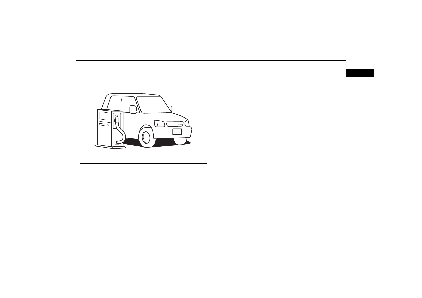
SERVICE STATION GUIDE
1. Fuel (see section 1)
2. Engine hood (see section 5)
3. Tire changing tools (see section 8)
4. Engine oil dipstick <Yellow>
(see section 7)
5. Automatic transaxle fluid dipstick
<Red> (see section 7)
6. Engine coolant (see section 7)
7. Windshield washer fluid
(see section 7)
8. Battery (see section 7)
9. Tire pressure (see tire information
label on driver’s door lock pillar)
10. Spare tire (see section 7)
2
LHD: Left Hand Drive
RHD: Right Hand Drive
(RHD)9
7
4
5
6
8
2
(RHD)
(LHD)2
9
(LHD)
3
10
1
52KM127
51KM0-01E
Page 8

MEMO
51KM0-01E
Page 9
TABLE OF CONTENTS
FUEL RECOMMENDATION 1
BEFORE DRIVING 2
OPERATING YOUR VEHICLE 3
DRIVING TIPS 4
OTHER CONTROLS AND EQUIPMENT 5
VEHICLE LOADING AND TOWING 6
INSPECTION AND MAINTENANCE 7
EMERGENCY SERVICE 8
APPEARANCE CARE 9
GENERAL INFORMATION 10
SPECIFICATIONS 11
INDEX 12
51KM0-01E
Page 10
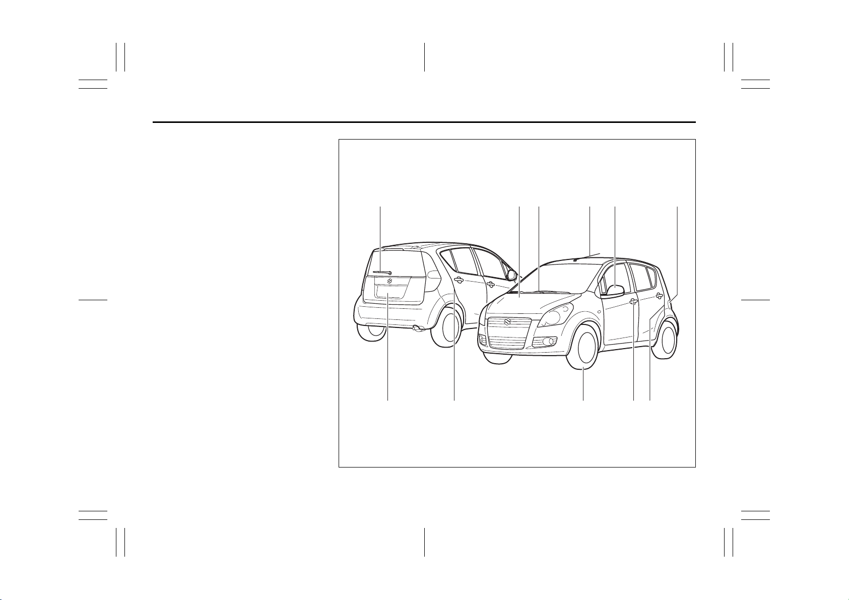
ILLUSTRATED TABLE OF CONTENTS
EXTERIOR
1. Rear window wiper (P. 2-62)
2. Engine hood (P. 5-31)
3. Windshield wiper and washer
(P. 2-60)
4. Radio antenna (P. 5-11)
5. Outside rearview mirror (P. 2-11)
6. Fuel filler cap (P. 5-30)
7. Tailgate (P. 2-5)
8. Child-proof locks (rear door) (P. 2-4)
9. Tires (P. 7-21)
10. Door locks (P. 2-2), Keys (P. 2-1)
EXAMPLE
1 2 3 4 5 6
7 8 9 10 8
51KM014
51KM0-01E
Page 11
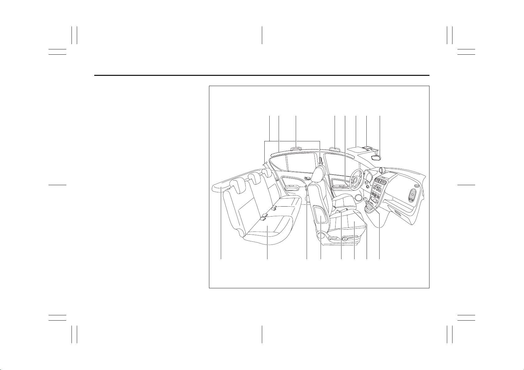
ILLUSTRATED TABLE OF CONTENTS
INTERIOR
1. Seat belts (P. 2-18)
2. Curtain air bags (if equipped)
(P. 2-40)
3. Assist grips (P. 5-34)
4. Eyeglass holder (P. 5-35)
5. Electric mirrors control switch
(if equipped) (P. 2-12)
Electric window controls (P. 2-9)
6. Sun visor (P. 5-32)
7. Interior light (P. 5-32)
8. Inside rearview mirror (P. 2-11)
9. Luggage compartment cover (P. 5-38)
10. Rear seats (P. 2-16)
11. Manual window control (P. 2-9)
12. Side air bags (if equipped) (P. 2-40)
13. Parking brake lever (P. 3-5)
Front seat heater switch (if equipped)
(P. 2-15)
14. Front seats (P. 2-13)
15. Cup holder (P. 5-36)
16. Gearshift lever (P. 3-9)
EXAMPLE
1 2
9 10 11 12 13 14 15
3 4 6 7 8
5
16
52KM126
51KM0-01E
Page 12
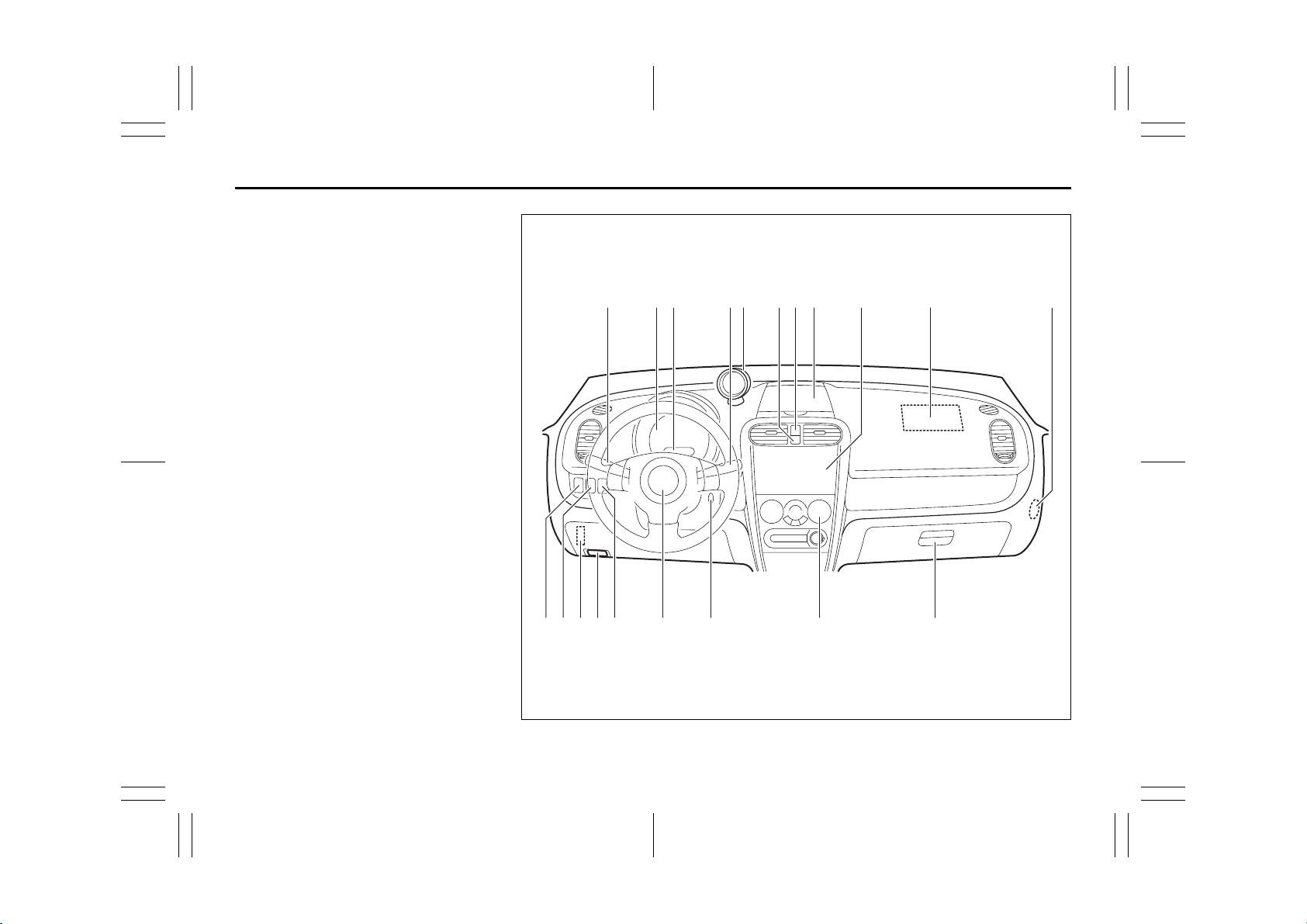
ILLUSTRATED TABLE OF CONTENTS
INSTRUMENT PANEL
1. Lighting control lever (P. 2-57)/
Turn signal control lever (P. 2-59 )
2. Instrument cluster (P. 2-46)
3. Odometer (P. 2-54)/
Tripmeter (P. 2-54)/Clock (P. 5-9)/
Information display (if equipped)
(P. 5-8)
4. Windshield wiper and washer switch
(P. 2-60)/Rear window wiper and
washer switch (if equipped) (P. 2-62)
5. Tachometer (if equipped) (P. 2-56)
6. Front passenger air bag deactivation
control indicator (if equipped)
(P. 2-44)
7. Hazard warning switch (P. 2-60)
8. Instrument panel upper tray (P. 5-35)
9. Audio (if equipped) (P. 5-12)
10. Air bag (P. 2-37)
11. Front passenger air bag deactivation
switch (if equipped) (P. 2-44)
12. Front fog light switch (if equipped)
(P. 2-58)
13. Headlight leveling switch (if equipped)
(P. 2-59)
14. Fuse box (P. 7-25)
15. Hood release (P. 5-31)
16. “TCSS OFF” switch (if equipped)
(P. 3-17)
17. Ignition switch (P. 3-3)
18. Heating and air conditioning system
(if equipped) (P. 5-1)
19. Glove box (P. 5-35)
EXAMPLE
2 51 111043 876 9
1710 181412 1615 1913
52KM003
51KM0-01E
Page 13
FUEL RECOMMENDATION
65D394
FUEL RECOMMENDATION
Fuel Recommendation ........................................................ 1-1
1
51KM0-01E
Page 14
Fuel Recommendation: 1, 2
FUEL RECOMMENDATION
Fuel Recommendation
EXAMPLE
52KM129
If your vehicle is not fitted with a restrictor
in the fuel filler pipe then you may use
leaded or unleaded gasoline with an
octane number (RON) of 85 or higher.
Note, it is preferable to use unleaded gasoline.
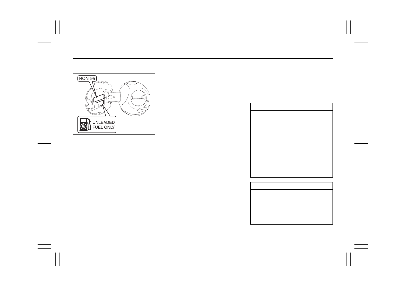
If your vehicle is fitted with a restrictor in
the fuel filler pipe then you must use
unleaded gasoline with an octane number
(RON) of 91 or higher (or RON of 95 or
higher if it is stated on the fuel filler lid).
These vehicles are also identified by a
label attached near the fuel filler pipe that
states: “UNLEADED FUEL ONLY”, “NUR
UNVERBLEITES BENZIN”, “ENDAST
BLYFRI BENSIN” or “SOLO GASOLINA
SIN PLOMO”.
If the “RON 95” label is attached, you must
use unleaded gasoline with an octane
number (RON) of 95 or higher.
Gasoline/Ethanol blends
Blends of unleaded gasoline and ethanol
(grain alcohol), also known as gasohol, are
commercially available in some areas.
Blends of this type may be used in your
vehicle if they are no more than 10% ethanol. Make sure this gasoline-ethanol blend
has octane ratings no lower than those
recommended for gasoline.
Gasoline/Methanol blends
Blends of unleaded gasoline and methanol
(wood alcohol) are also commercially available in some areas. DO NOT USE fuels
containing more than 5% methanol under
any circumstances. Fuel system damage
or vehicle performance problems resulting
from the use of such fuels are not the
responsibility of SUZUKI and may not be
covered under the New Vehicle Warranty.
Fuels containing 5% or less methanol may
be suitable for use in your vehicle if they
contain cosolvents and corrosion inhibitors.
NOTE:
If you are not satisfied with the driveability
or fuel economy of your vehicle when you
are using a gasoline/alcohol blend, you
should switch back to unleaded gasoline
containing no alcohol.
Diesel Engine
The diesel fuel should be with Cetane
Number (CN) higher than 51 and sulfur
content less than 10 ppm (parts per million). SUZUKI recommends to use the diesel fuel conformable to EN590. Do not use
marine diesel fuel, heating oils and so
forth.
CAUTION
The fuel tank has an air space to
allow for fuel expansion in hot
weather. If you continue to add fuel
after the filler nozzle has automatically shut off or an initial blowback
occurs, the air chamber will become
full. Exposure to heat when fully
fuelled in this manner will result in
leakage due to fuel expansion. To
prevent such fuel leakage, stop filling
after the filler nozzle has automatically shut off, or when using an alternative non automatic system, initial
vent blowback occurs.
CAUTION
Be careful not to spill fuel containing
alcohol while refueling. If fuel is
spilled on the vehicle body, wipe it up
immediately. Fuels containing alcohol can cause paint damage, which is
not covered under the New Vehicle
Limited Warranty.
1-1
51KM0-01E
Page 15
BEFORE DRIVING
BEFORE DRIVING
60G404
Keys ...................................................................................... 2-1
Door Locks .......................................................................... 2-2
Keyless Entry System Transmitter (if equipped) ............. 2-6
Theft Deterrent Light ........................................................... 2-8
Windows .............................................................................. 2-9
Mirrors .................................................................................. 2-11
Heated Rear Window and Heated Outside Rearview
Mirrors (if equipped) Switch ............................................... 2-12
Front Seats .......................................................................... 2-13
Rear Seats ............................................................................ 2-16
Seat Belts and Child Restraint Systems ........................... 2-18
Child Restraint System for EU Countries ......................... 2-29
Supplemental Restraint System (air bags)
(if equipped) ......................................................................... 2-37
Instrument Cluster .............................................................. 2-46
Warning and Indicator Lights ............................................ 2-47
Transaxle Selector Position Indicator (if equipped) ........ 2-54
Speedometer/Odometer/Trip meter/Meter Illumination
Control ................................................................................. 2-54
Tachometer (if equipped) ................................................... 2-56
Fuel Gauge ........................................................................... 2-56
Lighting Control Lever ........................................................ 2-57
Front Fog Light Switch (if equipped) ................................ 2-58
Rear Fog Light Switch (if equipped) .................................. 2-58
Headlight Leveling Switch (if equipped) ........................... 2-59
Turn Signal Control Lever .................................................. 2-59
Hazard Warning Switch ...................................................... 2-60
Windshield Wiper and Washer Lever ................................ 2-60
Rear Window Wiper/Washer Switch (if equipped) ........... 2-62
Tilt Steering Lock Lever (if equipped) ............................... 2-62
Horn ...................................................................................... 2-63
2
51KM0-01E
Page 16
Fuel Recommendation: 1, 2
BEFORE DRIVING
Keys
EXAMPLE
51KM024
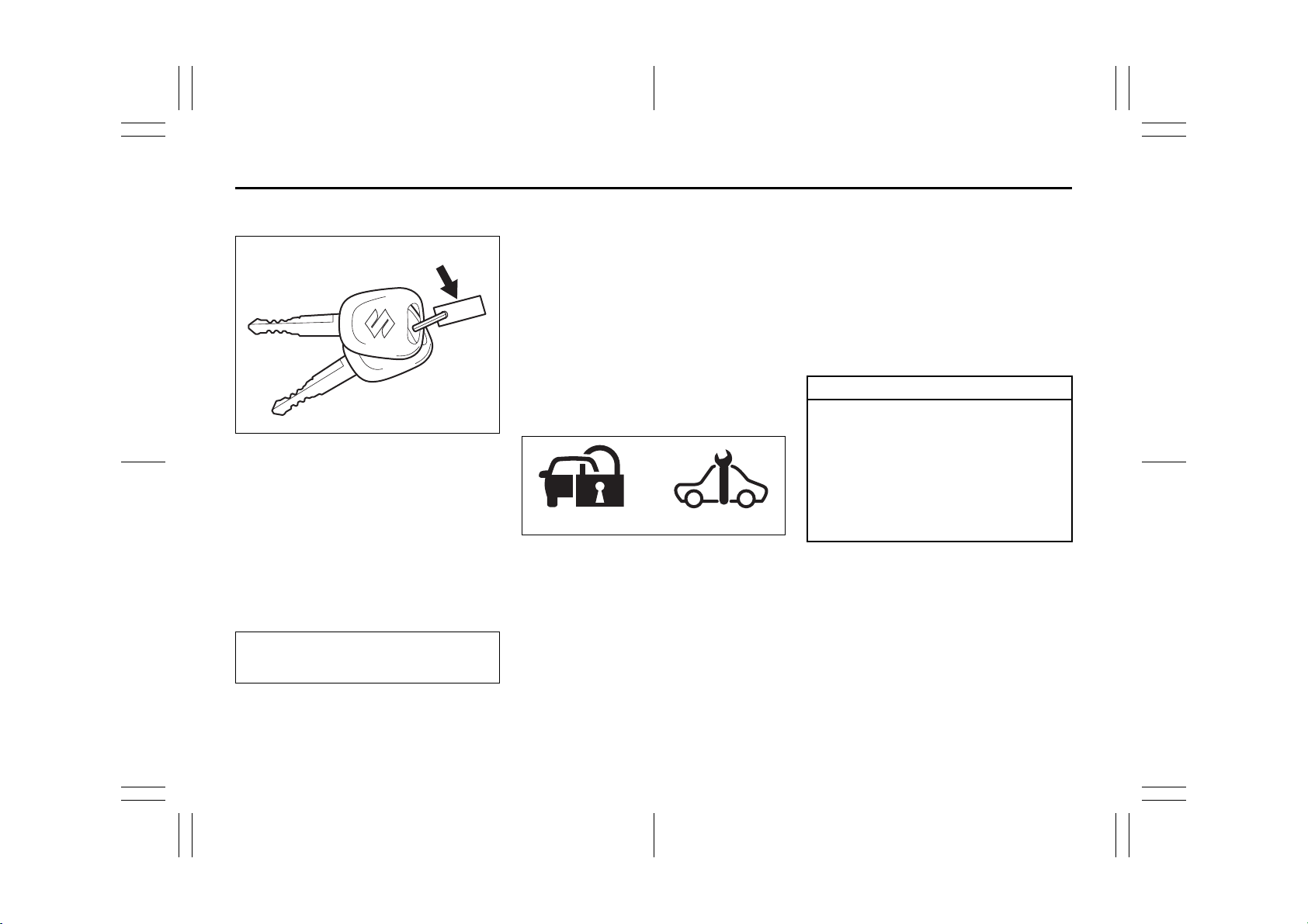
Your vehicle comes with a pair of identical
keys. Keep the spare key in a safe place.
One key can open all of the locks on the
vehicle.
The key identification number is stamped
on a metal tag provided with the keys or on
the keys. Keep the tag (if equipped) in a
safe place. If you lose your keys, you will
need this number to have new keys made.
Write the number below for your future reference.
KEY NUMBER:
Immobilizer System (if equipped)
This system is designed to help prevent
vehicle theft by electronically disabling the
engine starting system.
The engine can be started only with your
vehicle’s original immobilizer ignition key
which has an electronic identification code
programmed into it. The key communicates the identification code to the vehicle
when the key is turned to the “ON” position. If you need to make spare keys, see
your SUZUKI dealer. The vehicle must be
programmed with the correct identification
code for the spare keys. A key made by an
ordinary locksmith will not work.
(1) (2)
62J127
If the Immobilizer system light (1) for gasoline engine or service vehicle soon (SVS)
light (2) for diesel engine blinks when the
ignition switch is in the “ON” position, there
may be something wrong with your key or
with the immobilizer system. Ask your
SUZUKI dealer to inspect the system.
sible to have the lost one deactivated,
then have the new key made by them.
• If you own other vehicles with immobilizer keys, keep those keys away from
the ignition switch when using your
SUZUKI, or the engine may not be
started because they may interfere with
your SUZUKI’s immobilizer system.
• In case of attaching any metal objects to
the immobilizer key, it may not start the
engine.
CAUTION
The immobilizer key is a sensitive
electronic instrument. To avoid damaging the immobilizer key:
• Do not expose it to impacts, moisture or high temperature such as
on the dashboard under direct sunlight.
• Keep the immobilizer key away
from magnetic objects.
This immobilizer system, model
5WK49181 and 5WK49182 for gasoline
engine or model 5WK49183 and
5WK49184 for diesel engine are in compliance with the essential requirements and
other provisions of the Directive 1999/5/
EC.
2-1
NOTE:
• If you lose your Immobilizer ignition key,
see your SUZUKI dealer as soon as pos-
51KM0-01E
Page 17
Keys: 8
BEFORE DRIVING
Ignition Key Reminder (if equipped)
A buzzer sounds intermittently to remind
you to remove the ignition key if it is in the
ignition switch when the driver’s door is
opened.
Door Locks
Side Door Locks
Driver’s door
LOCK
UNLOCK
Front
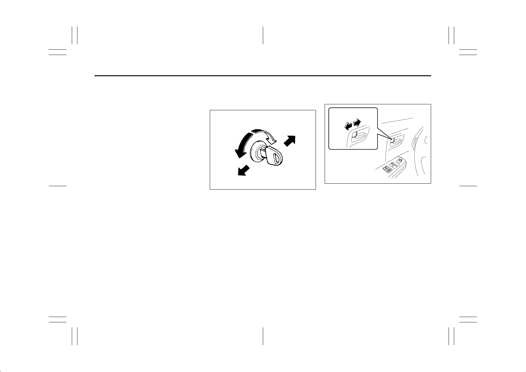
To lock a driver’s door from outside the
vehicle:
• Insert the key and turn the top of the key
toward the rear of the vehicle, or
• Turn the lock knob forward then pull and
hold the door handle as you close the
door.
To unlock a driver’s door from outside the
vehicle, insert the key and turn the top of
the key toward the front of the vehicle.
To lock a front passenger’s door from outside the vehicle, turn the lock knob forward
and hold the door handle up as you close
the door.
Rear
60B008
To lock a rear door from outside the vehicle, turn the lock knob forward and close
the door.
EXAMPLE
52KM138
UNLOCK
LOCK
To lock a door from inside the vehicle, turn
the lock knob forward. Turn the lock knob
backward to unlock the door. You do not
need to hold the door handle up as you
close the door.
2-2
51KM0-01E
Page 18
Door Locks: 3, 5, 8
BEFORE DRIVING
Central Door Locking System
Driver’s door
UNLOCK
Front
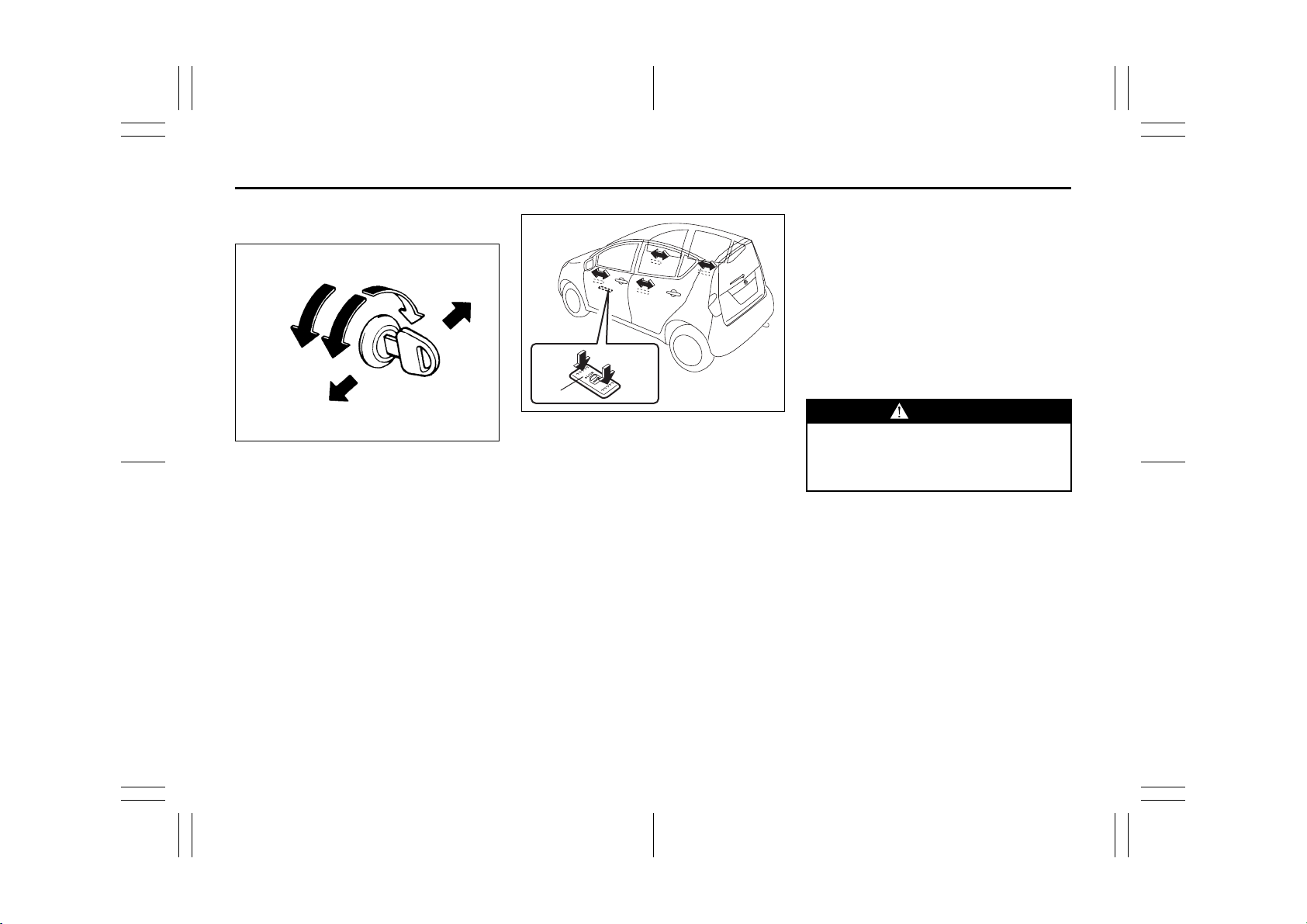
You can lock and unlock all doors (including the tailgate) simultaneously by using
the key in the driver’s door lock.
To lock all doors simultaneously, insert the
key in the driver’s door lock and turn the
top of the key toward the rear of the vehicle
once.
To unlock all doors simultaneously, insert
the key in a driver’s door lock and turn the
top of the key toward the front of the vehicle twice.
To unlock the driver’s door only, insert the
key in that door lock and turn the top of the
key toward the front of the vehicle once.
LOCK
Rear
54G294
EXAMPLE
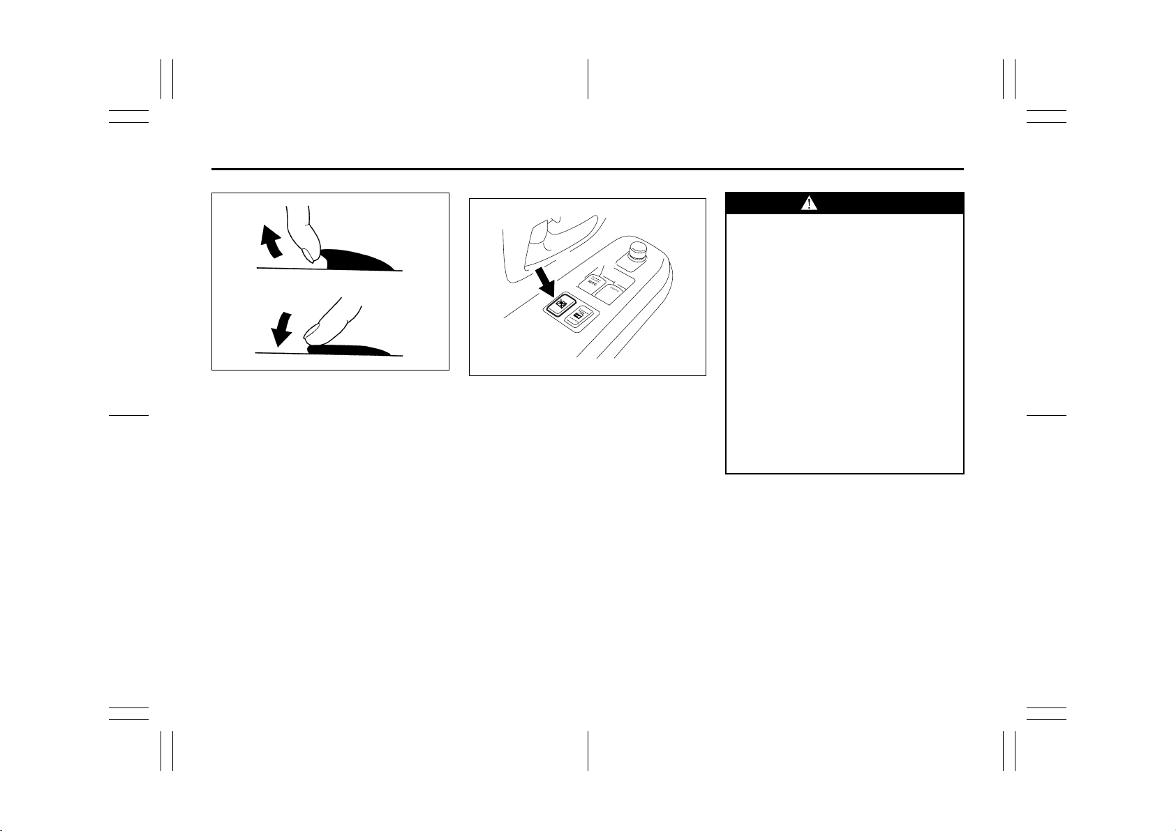
LOCK UNLOCK
(1)
51KM002
You can also lock or unlock all doors
(including the tailgate) by depressing the
front or rear of the switch (1), respectively.
NOTE:
• If your vehicle is equipped with keyless
entry system, you can also lock or
unlock all doors by operating the transmitter. Refer to “Keyless Entry System
Transmitter”.
Dead Lock System (if equipped)
This system is designed to help prevent
tamper-unlocking of the door locks.
You can activate this system by turning the
key in the driver’s door lock.
NOTE:
• If your vehicle is equipped with the keyless entry system, you can activate the
dead lock system by operating the transmitter. Refer to “Keyless Entry System
Transmitter” in this section.
WARNING
Do not activate the dead lock system
if there are occupants in the vehicle.
They will be locked in the vehicle and
cannot unlock the doors from inside.
NOTE:
• The dead lock system will not operate if
one or more door(s) is(are) not closed
and latched completely. Make sure all
doors (including the tailgate) are completely closed and latched when activating the dead lock system.
2-3
51KM0-01E
Page 19
Door Locks: 3, 5, 8
BEFORE DRIVING
• The dead lock system is released automatically allowing all the side doors to be
unlocked when the ignition switch is
turned to the “ON” position.
Rear
Front
83E107
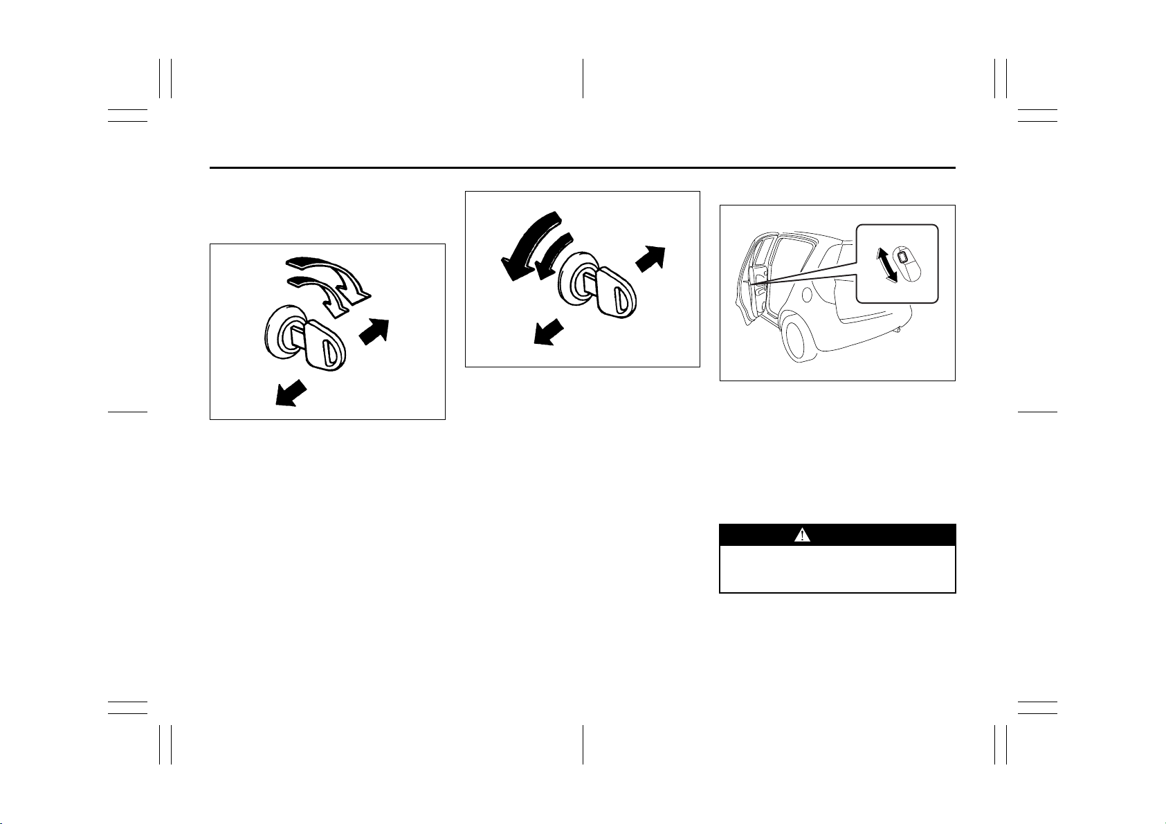
To activate this system:
Insert the key in the driver’s door lock and
turn the top of the key toward the rear of
the vehicle twice within 3 seconds.
You can not use the lock knobs to unlock
the side doors when this system is activated.
Rear
Front
83E105
To release this system:
To unlock all the side doors, insert the key
in the driver’s door lock and turn the top of
the key toward the front of the vehicle
twice.
To unlock only the driver’s door, insert the
key in that door lock and turn the top of the
key toward the front of the vehicle once.
Child-Proof Locks (rear door)
EXAMPLE
(2)
(1)
52KM007
As illustrated, a child-proof lock is provided
for both rear doors. When the lock lever is
in position (1), the child-proof lock is
locked, and when in position (2), the childproof lock is unlocked. When the childproof lock is in the locked position, the rear
door cannot be opened from the inside
even if the inside door lock is unlocked but
can be opened from the outside.
WARNING
Be sure to place the child-proof lock
in the locked position whenever children are seated in the rear.
2-4
51KM0-01E
Page 20
Door Locks: 3, 5, 8
BEFORE DRIVING
Tailgate
Type1
EXAMPLE
(1)
51KM003
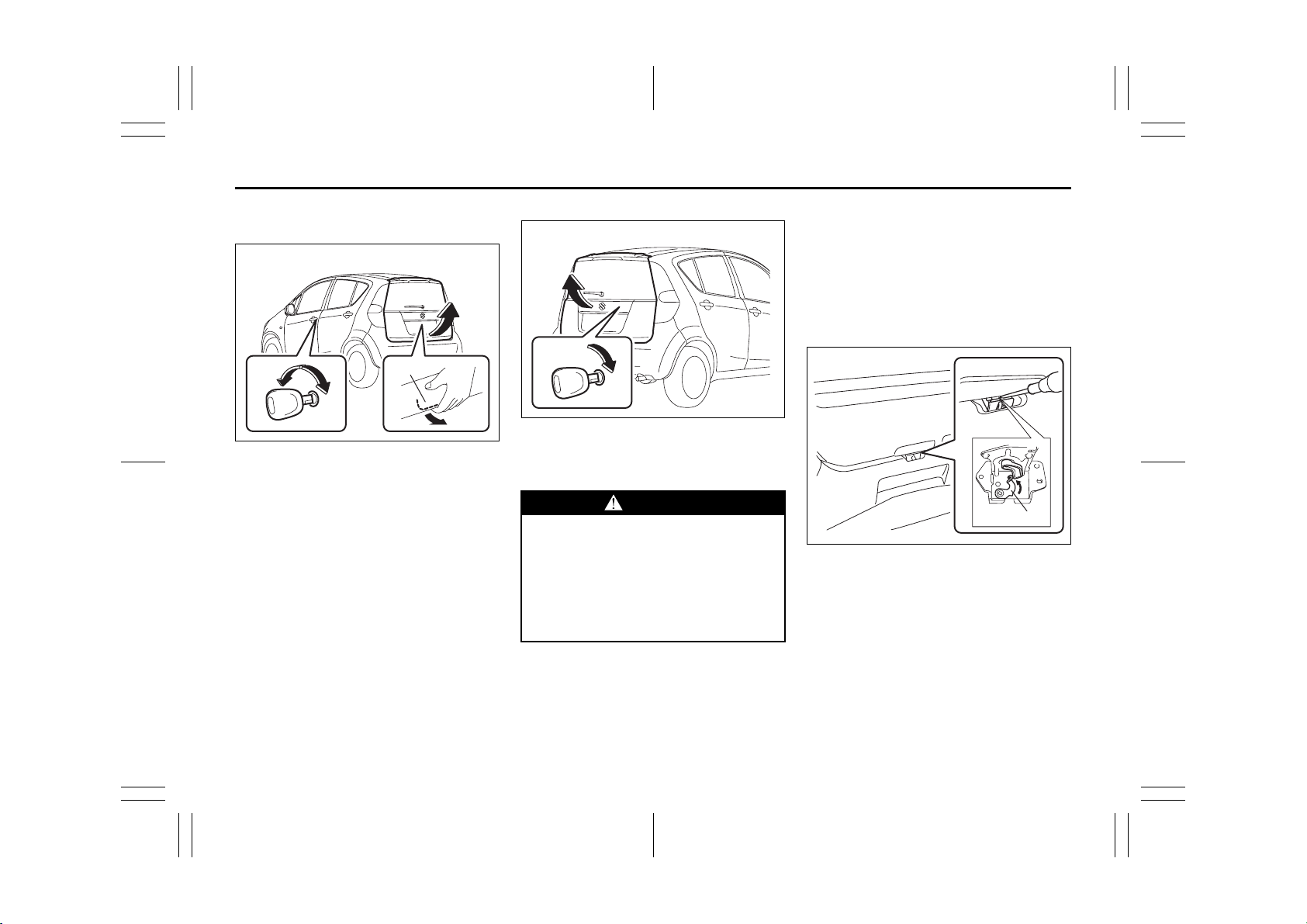
(1) Tailgate handle
You can lock and unlock the tailgate by
using the key in the driver’s door lock.
To open the tailgate, pull up and hold the
tailgate handle (1) and lift the tailgate.
Type2
EXAMPLE
51KM004
To open the tailgate, insert the key and
turn it clockwise to unlatch and lift the tailgate.
WARNING
Always make sure that the tailgate is
closed and latched securely. Completely closing the tailgate helps prevent occupants from being thrown
from the vehicle in the event of an
accident. Completely closing it also
helps keep exhaust gases from entering the car.
If you can not unlatch the tailgate by pulling
up the tailgate handle (1) due to a discharged battery or malfunction, follow the
procedures below to unlatch the tailgate
from inside the vehicle.
1) Fold the rear seat forward for easier
access. Refer to “Folding Rear Seats”
section for details on how to fold the
rear seat forward.
(2)
62J132
2) Push open the tailgate from inside by
pushing up on the emergency lever (2)
using a flat blade screw driver or the
jack handle. The tailgate will be latched
again by closing the tailgate simply.
If the tailgate can not be unlatched by pulling up the tailgate handle (1), have the
vehicle inspected by your SUZUKI dealer.
2-5
51KM0-01E
Page 21
Door Locks: 3, 5, 8
BEFORE DRIVING
WARNING
• To avoid injury, do not use your finger to push the emergency lever.
• Make sure there is not anyone near
the tailgate when pushing open the
tailgate from inside the vehicle.
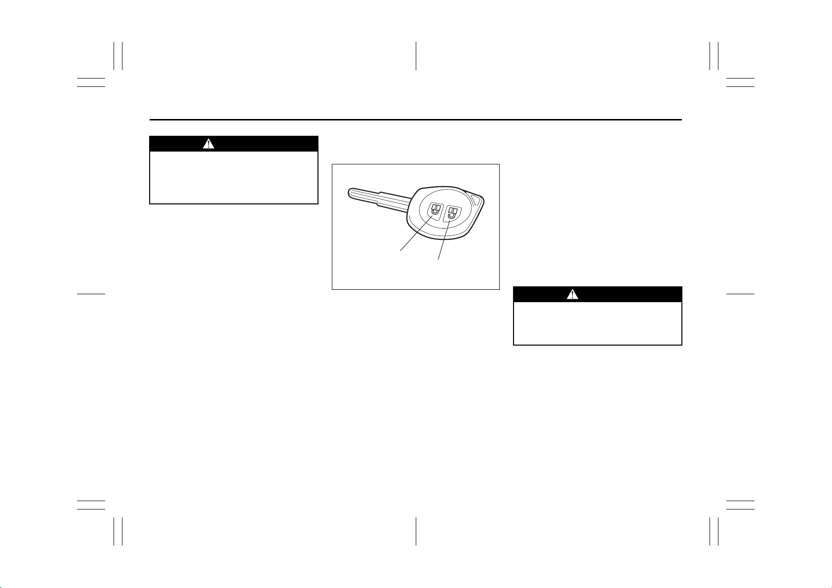
Keyless Entry System
Transmitter (if equipped)
(1)
(2)
81A184
(1) “LOCK” button
(2) “UNLOCK” button
There are two ways to lock or unlock all
doors (including the tailgate) simultaneously by operating the transmitter near
the vehicle.
Central door locking system
• To lock all doors, push the “LOCK” button (1) once.
• To unlock only the driver’s door, push the
“UNLOCK” button (2) once.
• To unlock other doors, push the
“UNLOCK” button (2) once again.
Central door locking system with the
dead lock system (if equipped)
If you want to prevent tamper-unlocking of
the door locks, use this method. When the
dead lock system is activated, operating
the lock knobs will not unlock the side
doors.
To activate this system:
To lock all doors, push the “LOCK” button
(1) twice within 3 seconds.
To release this system:
• To unlock only the driver’s door, push the
“UNLOCK” button (2) once.
• To unlock other doors, push the
“UNLOCK” button (2) once again.
WARNING
Do not activate the dead lock system
if there are occupants in the vehicle.
They will be locked in the vehicle and
cannot unlock the doors from inside.
2-6
51KM0-01E
Page 22
Windows: 3, 8
BEFORE DRIVING
The turn signal lights will flash once when
the doors are locked and then the turn signal lights will flash once again when the
doors are locked with the dead lock system.
When the doors are unlocked:
• The turn signal lights will flash twice.
• If the interior light switch is in the middle
position, the interior light will turn on for
about 15 seconds and then fade out. If
you insert the key into the ignition switch
during this time, the light will start to fade
out immediately.
Be sure the doors are locked after you
operate the “LOCK” button. If no door is
opened within about 30 seconds after the
“UNLOCK” button is operated, the doors
will automatically lock again.
NOTE:
• The maximum operating distance of the
keyless entry system transmitter is about
5 m (16 ft.), but this can vary depending
on the surroundings, especially near
other transmitting devices such as radio
towers or CB (Citizen’s Band) radios.
• The door locks can not be operated with
the transmitter if the ignition switch is in a
position other than “LOCK”, or the ignition key is inserted in the ignition switch.
• When any door is open, the door locks
can be operated only unlock with the
transmitter, and the turn signal light will
not flash.
• If you lose one of the transmitters, ask
your SUZUKI dealer as soon as possible
for a replacement. Be sure to have your
dealer program the new transmitter code
in your vehicle’s memory so that the old
code is erased.
CAUTION
The transmitter is a sensitive electronic instrument. To avoid damaging
the transmitter:
• Do not expose it to impacts, moisture or high temperature such as by
leaving it on the dashboard under
direct sunlight.
• Keep the transmitter away from
magnetic objects such as a television.
Replacement of the Battery
If the transmitter becomes unreliable,
replace the battery.
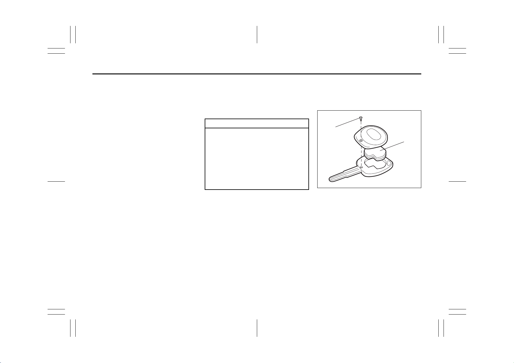
To replace the battery of the transmitter:
(1)
(2)
81A185
1) Remove the screw (1), and open the
transmitter cover.
2) Remove the transmitter (2).
2-7
51KM0-01E
Page 23
Windows: 3, 8
Mirrors: 3, 8
BEFORE DRIVING
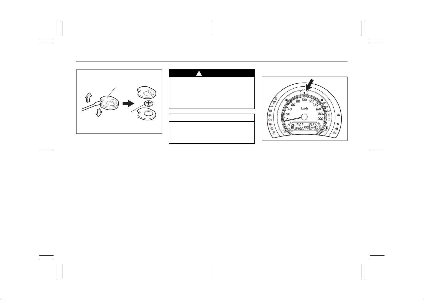
(2)
(3)
52KM130
3) Put the edge of a flat blade screw driver
in the slot of the transmitter (2) and pry
it open.
4) Replace the battery (3) (Lithium disctype CR1620 or equivalent) so its + terminal faces the “+” mark of the transmitter.
5) Close the transmitter and install it into
the transmitter holder.
6) Close the transmitter cover, install and
tighten the screw (1).
7) Make sure the door locks can be operated with the transmitter.
8) Dispose of the used battery properly
according to applicable rules or regulations. Do not dispose of lithium batteries with ordinary household trash.
WARNING
Swallowing a lithium battery may
cause serious internal injury. Do not
allow anyone to swallow a lithium
battery. Keep lithium batteries away
from children and pets. If swallowed,
contact a physician immediately.
CAUTION
The transmitter is a sensitive electronic instrument. To avoid damaging
it, do not expose it to dust or moisture or tamper with internal parts.
The Keyless Entry System, Transmitter
model TS002 and Receiver model R62J1
or R51K0 are in compliance with the
essential requirements and other provisions of Directive 1999/5/EC.
Theft Deterrent Light
EXAMPLE
51KM015
This light will blink with the ignition switch
in the “OFF” or “ACC” position. The blinking light is intended to deter theft by leading others to believe that the vehicle is
equipped with a security system.
2-8
51KM0-01E
Page 24
Mirrors: 3, 8
BEFORE DRIVING
Windows
Manual Window Control
(if equipped)
EXAMPLE
60G010
Raise or lower the door windows by turning
the handle located on the door panel.
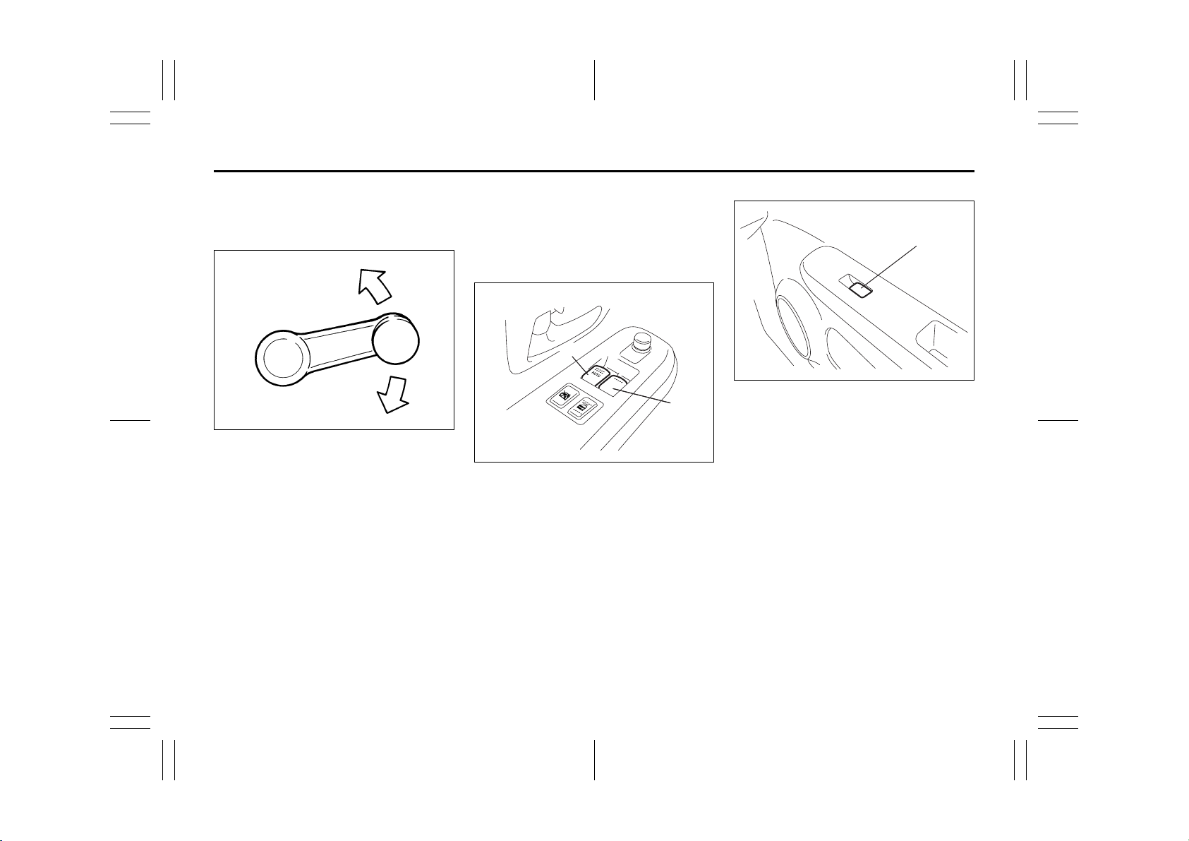
Electric Window Controls
(if equipped)
The electric windows can only be operated
when the ignition switch is in the “ON” position.
Driver’s door
EXAMPLE
(1)
(2)
52KM010
The driver’s door has a switch (1) to operate the driver’s window, and a switch (2) to
operate the front passenger’s window.
Passenger’s door
EXAMPLE
(3)
52KM012
The passenger’s door has a switch (3) to
operate that passenger’s window.
2-9
51KM0-01E
Page 25
Seat Adjustment: 3
CLOSE
OPEN
To open a window, push the top part of the
switch and to close the window, lift up the
top part of the switch.
The driver’s window has an “auto-down”
feature for added convenience (at toll
booths or drive-through restaurants, for
example). This means you can open the
window without holding the window switch
in the “Down” position. Press the driver’s
window switch completely down and
release it. To stop the window before it
reaches the bottom, pull the switch up
briefly.
81A009
Lock switch
EXAMPLE
52KM013
The driver’s door also has a lock switch for
the passenger’s windows. When you push
in the lock switch, the passenger’s windows can not be raised or lowered by operating any of the switches (2) or (3). To
restore normal operation, release the lock
switch by pushing again.
BEFORE DRIVING
WARNING
• You should always lock the passenger’s window operation when there
are children in the vehicle. Children
can be seriously injured if they get
part of their body caught by the
window during operation.
• To avoid injuring an occupant by
window entrapment, be sure no
part of the occupant’s body such
as hands or head is in the path of
the electric windows when closing
them.
• Always remove the ignition key
when leaving the vehicle even if a
short time. Also do not leave children alone in a parked vehicle.
Unattended children could use the
electric window switches and get
trapped by the window.
2-10
51KM0-01E
Page 26
Seat Adjustment: 3
Adjustable Head Restraints: 3
BEFORE DRIVING
Mirrors
Inside Rearview Mirror
52KM015
(1)
Day driving Night driving
52KM016
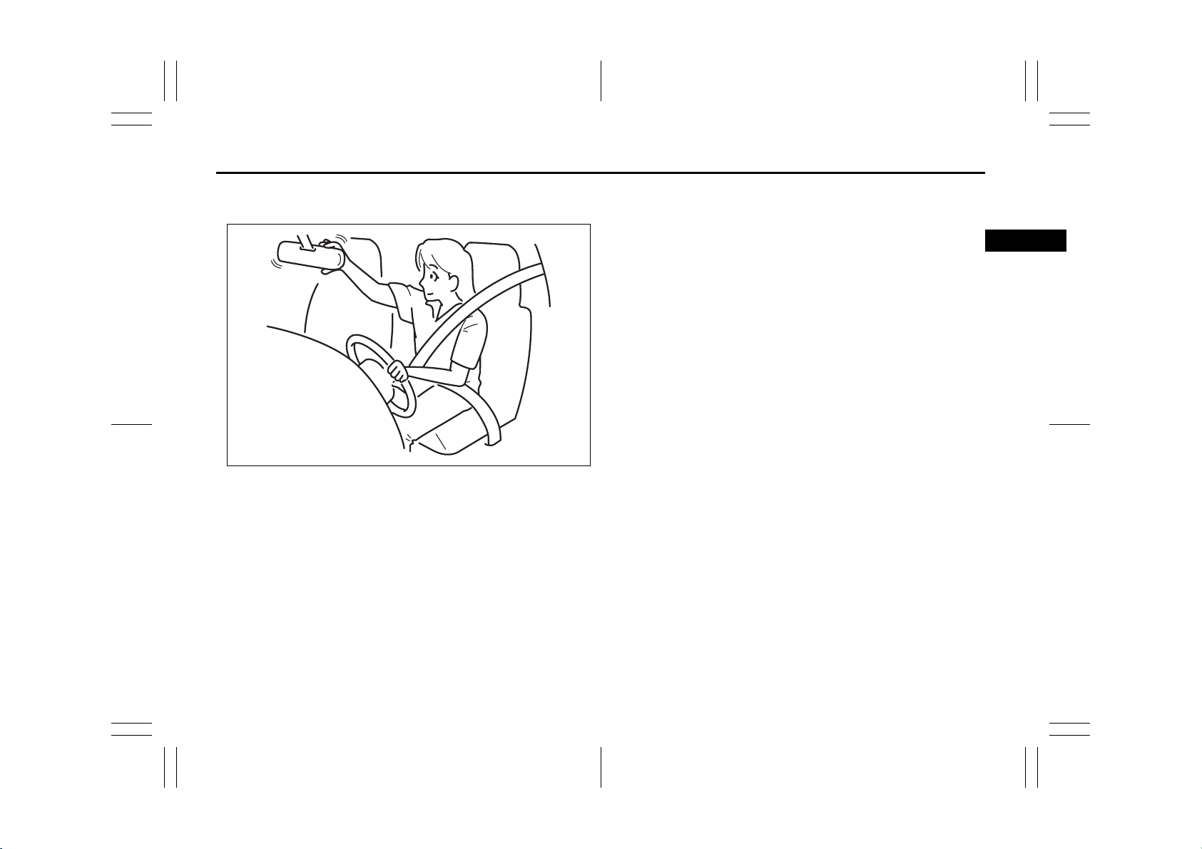
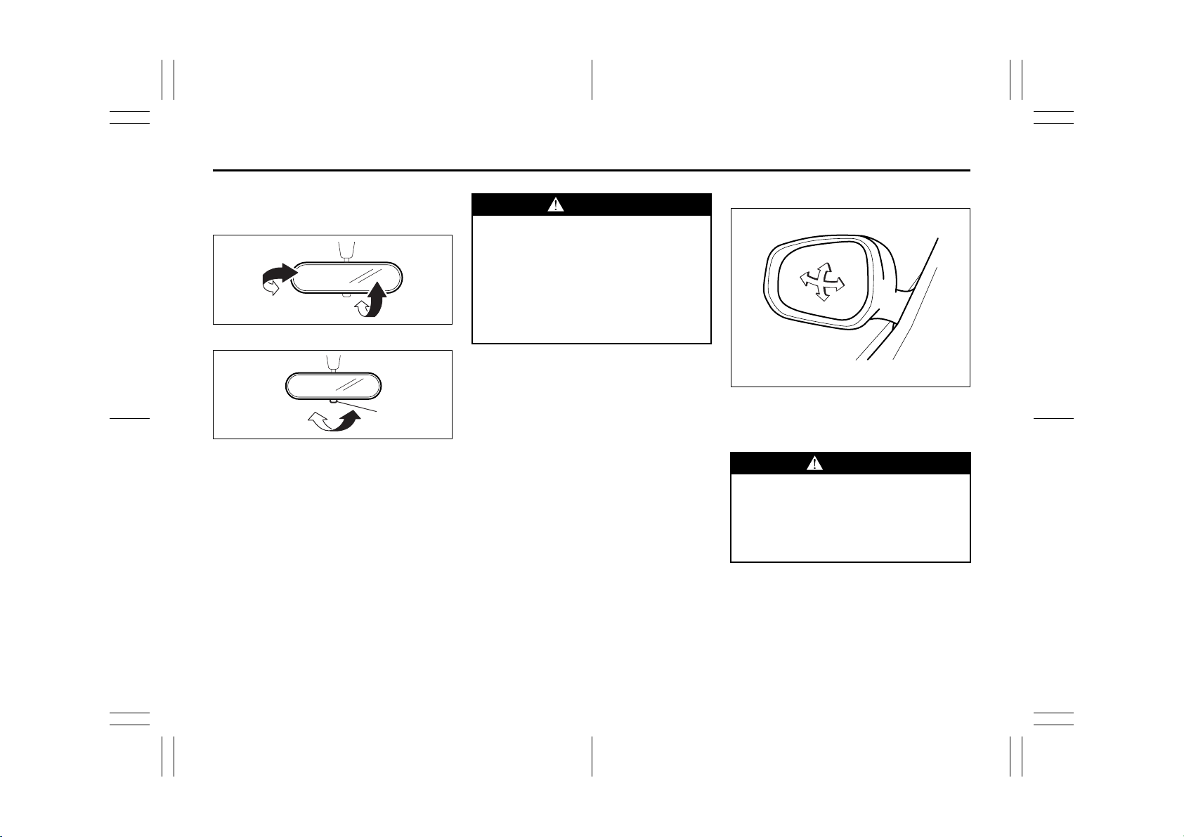
You can adjust the inside rearview mirror
by hand so as to see the rear of your vehicle in the mirror. To adjust the mirror, set
the selector tab (1) to the day position,
then move the mirror up, down or sideways
by hand to obtain the best view.
When driving at night, you can move the
selector tab to the night position to reduce
glare from the headlights of vehicles
behind you.
WARNING
Outside Rearview Mirrors
• Always adjust the mirror with the
selector set to the day position.
• Only use the night position if it is
necessary to reduce glare from the
headlights of vehicles behind you.
Be aware that in this position you
may not be able to see some
objects that could be seen in the
day position.
52KM017
Adjust the outside rearview mirrors so you
can just see the side of your vehicle in the
mirrors.
WARNING
Be careful when judging the size or
distance of a vehicle or other object
seen in the side convex mirror. Be
aware that objects look smaller and
appear farther away than when seen
in a flat mirror.
2-11
51KM0-01E
Page 27
Adjustable Head Restraints: 3
Seat Belts and Child Restraint Systems: 3
BEFORE DRIVING
Electric Mirrors (if equipped)
EXAMPLE
(1)
(2)
(3)
(4)
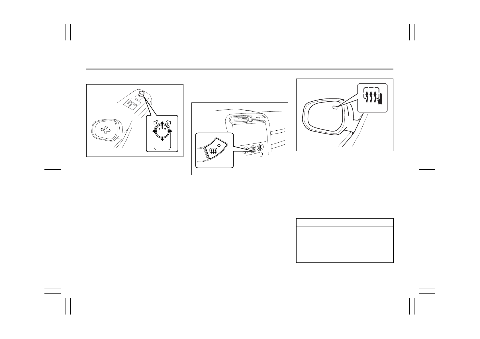
The switch to control the electric mirrors is
located on the driver’s door panel. You can
adjust the mirrors when the ignition switch
is in the “ACC” or “ON” position. To adjust
the mirrors:
1) Move the selector switch to the left or
right to select the mirror you wish to
adjust.
2) Press the outer part of the switch that
corresponds to the direction in which
you wish to move the mirror.
3) Return the selector switch to the center
position to help prevent unintended
adjustment.
(1)
(3)(2)
(4)
52KM018
Heated Rear Window and
Heated Outside Rearview
Mirrors (if equipped) Switch
(1)
EXAMPLE
52KM019
When the rear window is misted, push this
switch (1) to clear the window.
(2)
52KM020
If the driver’s outside rearview mirror has
the mark (2), it is also equipped with the
heated outside rearview mirrors. When you
push the switch (1), both the heated outside rearview mirrors and the heated rear
window will operate simultaneously.
An indicator light will be lit when the defogger is on. The defogger will work only
when the engine is running. To turn off the
defogger, push the switch again.
CAUTION
The heated rear window and the
heated outside rearview mirrors (if
equipped) use a large amount of electricity. Be sure to turn off after the
window and mirrors have become
clear.
2-12
51KM0-01E
Page 28
Seat Belts and Child Restraint Systems: 3
BEFORE DRIVING
NOTE:
• The defogger will work only when the
engine is running.
• The defogger will automatically turn off
after the defogger remains on for 15 minutes to prevent discharging of the battery.
Front Seats
Seat Adjustment
WARNING
Never attempt to adjust the driver’s
seat or seatback while driving. The
seat or seatback could move unexpectedly, causing loss of control.
Make sure that the driver’s seat and
seatback are properly adjusted
before you start driving.
WARNING
To avoid excessive seat belt slack,
which reduces the effectiveness of
the seat belts as a safety device,
make sure that the seats are adjusted
before the seat belts are fastened.
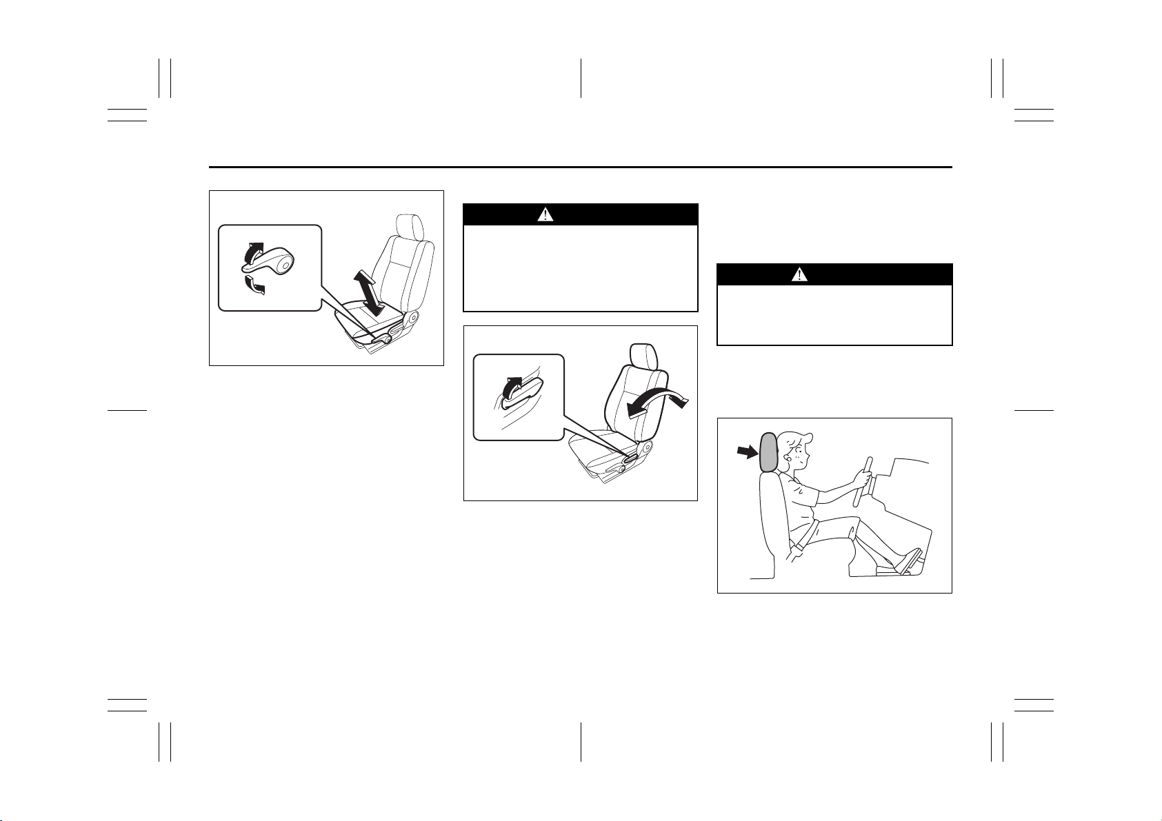
Adjusting Seat Position
EXAMPLE
63J222
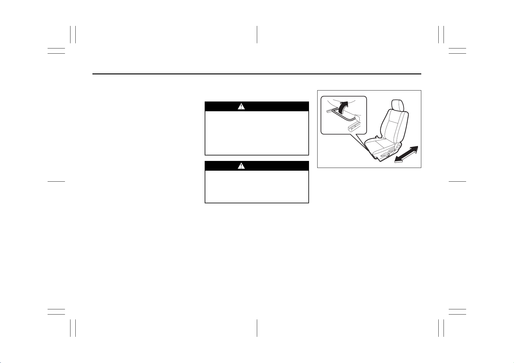
The adjustment lever for each front seat is
located under the front of the seat. To
adjust the seat position, pull up on the
adjustment lever and slide the seat forward
or rearward.
After adjustment, try to move the seat forward and rearward to ensure that it is
securely latched.
2-13
51KM0-01E
Page 29
Seat Belts and Child Restraint Systems: 3
BEFORE DRIVING
EXAMPLE
52KM021
If each front seat is equipped with a seat
height adjuster lever on the outboard side
of the seat, raise or lower the seat by pulling up or down the adjuster lever.
Adjusting Seatbacks
WARNING
All seatbacks should always be in an
upright position when driving, or seat
belt effectiveness may be reduced.
Seat belts are designed to offer maximum protection when seatbacks are
in the upright position.
EXAMPLE
63J221
To adjust the seatback angle of front seats,
pull up the lever on the outboard side of
the seat, move the seatback to the desired
position, and release the lever to lock the
seatback in place.
Adjustable Head Restraints
(if equipped)
Head restraints are designed to help
reduce the risk of neck injuries in the case
of an accident.
WARNING
• Never drive the vehicle with the
head restraints removed.
• Do not attempt to adjust the head
restraint while driving.
NOTE:
It may be necessary to recline the seatback to provide enough overhead clearance to remove the head restraint.
63J256
2-14
51KM0-01E
Page 30
Seat Belts and Child Restraint Systems: 3
BEFORE DRIVING
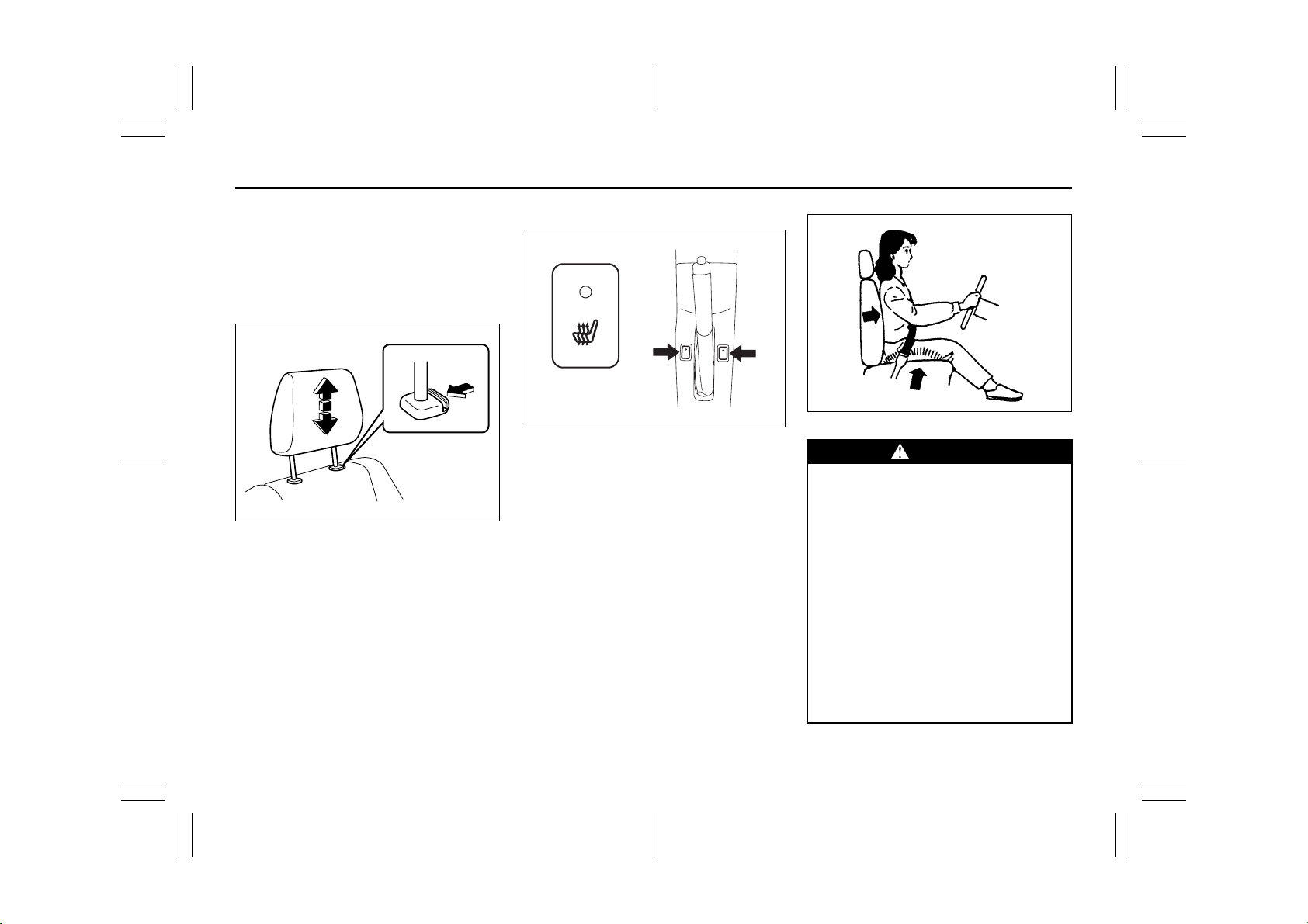
Adjust the head restraint to the position
which places the center of the head
restraint closest to the top of your ears. If
this is not possible for very tall passengers,
adjust the head restraint as high as possible.
Front
EXAMPLE
52KM022
To raise the front head restraint, pull
upward on the restraint until it clicks. To
lower the restraint, push down on the
restraint while holding in the lock lever. If a
head restraint must be removed (for cleaning, replacement, etc.), push in the lock
lever and pull the head restraint all the way
out.
Front Seat Heater (if equipped)
63J183
With the ignition switch in the “ON” position, push in one or both of the seat heater
switches to warm the corresponding
seat(s). The indicator light below the switch
will also come on. To turn off the seat
heater, push in the switch again. The indicator light below the switch will go off.
86G064
WARNING
Improperly using the seat heater can
be hazardous. An occupant can suffer burns even if the heating temperature is fairly low, if the occupant is
wearing thin pants, a thin skirt or
shorts and leaves the heater on for
long periods.
Avoid using the seat heater for these
occupants:
• People who have reduced feeling in
their legs, including the elderly or
those with certain disabilities.
• Small children, or anyone with sensitive skin.
• People who are asleep or under the
influence of alcohol or other drugs
which make them tired.
2-15
51KM0-01E
Page 31

Seat Belts and Child Restraint Systems: 3
BEFORE DRIVING
CAUTION
To avoid damaging the heater element:
• Do not subject the front seats to
heavy impacts, such as children
jumping on them.
• Do not cover the seat with any
insulating materials such as blankets or cushions.
Rear Seats
Adjustable Head Restraints
(if equipped)
Head restraints are designed to help
reduce the risk of neck injuries in the case
of an accident.
WARNING
• Never drive the vehicle with the
head restraints removed.
• Do not attempt to adjust the head
restraint while driving.
NOTE:
It may be necessary to recline the seatback to provide enough overhead clearance to remove the head restraint.
Adjust the head restraint to the position
which places the center of the head
restraint closest to the top of your ears. If
this is not possible for very tall passengers,
adjust the head restraint as high as possible.
Rear
EXAMPLE
64J023
To raise the rear head restraint, pull
upward on the restraint until it clicks. To
lower the restraint, push down on the
restraint while holding in the lock lever. If a
head restraint must be removed (for cleaning, replacement, etc.), push in the lock
lever and pull the head restraint all the way
out.
When installing a child restraint system,
raise the head restraint to the most upper
position.
2-16
51KM0-01E
Page 32

Seat Belts and Child Restraint Systems: 3
BEFORE DRIVING
Folding Rear Seats
The rear seat(s) of your vehicle can be
folded forward to provide additional cargo
space.
To fold the rear seats forward:
EXAMPLE
52KM023
1) Hook the webbing of the outboard lapshoulder belts (if equipped) in the belt
hangers.
CAUTION
• When you move a seatback, make
sure the belt webbings are hooked
in the seat belt hangers so the seat
belts are not caught by the seatback, seat hinge, or seat latch. This
helps prevent damage to the belt
system.
• Make sure the belt webbing is not
twisted.
2) Lower the adjustable head restraint (if
equipped) fully.
EXAMPLE
52KM024
3) For the split seat, pull the release lever
on the top of each split seat, and fold
the seatbacks forward.
For the bench seat, pull the both
release levers on the top of the bench
seat together, and fold the seatback forward.
CAUTION
After folding the rear seatback forward, do not allow any foreign material to enter the lock opening. This
may cause damage to the inside of
the lock and prevent the seatback
from being locked securely.
WARNING
If you need to carry cargo in the passenger compartment with the rear
seat back folded forward, be sure to
secure the cargo or it may be thrown
about, causing injury. Never pile
cargo higher than the seatbacks.
To return the seat to the normal position,
follow the procedure below.
WARNING
When returning the rear seatback to
the normal position, be careful that
your finger is not caught between the
lock and the striker.
CAUTION
When returning the rear seatback to
the normal position, make sure that
there is nothing around the striker.
Any foreign materials prevent the
seatback from being locked securely.
2-17
51KM0-01E
Page 33

Seat Belts and Child Restraint Systems: 3
BEFORE DRIVING
EXAMPLE
52KM025
Raise the seatback until it locks into place.
After returning the seat, try moving the
seatback to make sure they are securely
latched.
WARNING
Do not put your hand into the rear
seatback lock opening, or your finger
may get caught and be injured.
Red
LOCK UNLOCK
79J127
CAUTION
After securing the rear seatback,
make sure that it is locked securely. If
it is not, you will see red around in
the release lever.
CAUTION
• When returning the rear seatback
to the normal position, do not allow
any foreign material to enter the
lock opening. This may prevent the
seatback from being locked
securely.
• When returning the rear seatback
to the normal position, be sure to
handle it carefully by hand to avoid
any damage to the lock itself. Do
not push it by using some material
or by applying excessive force.
• As the lock is designed exclusively
for securing the rear seatback, do
not use it for any other purpose.
Incorrect use of it may cause damage to the inside of the lock and
prevent the seatback from being
locked securely.
Seat Belts and Child Restraint
Systems
65D231S
WARNING
Wear Your Seat Belts at All Times.
WARNING
An air bag supplements, or adds to,
the frontal crash protection offered
by seat belts. The driver and all passengers must be properly restrained
by wearing seat belts at all times,
whether or not an air bag is mounted
at their seating position, to minimize
the risk of severe injury or death in
the event of a crash.
2-18
51KM0-01E
Page 34

Seat Belts and Child Restraint Systems: 3
BEFORE DRIVING
Above the pelvis
65D606 65D201 65D199
Across the pelvis
as low as possible
across the hips
WARNING
• Never allow persons to ride in the
cargo area of a vehicle. In the event
of an accident, there is a much
greater risk of injury for persons
who are not riding in a seat with
their seat belt securely fastened.
• Seat belts should always be
adjusted as follows:
– the lap portion of the belt should
be worn low across the pelvis,
not across the waist.
– the shoulder straps should be
worn on the outside shoulder
only, and never under the arm.
– the shoulder straps should be
away from your face and neck,
but not falling off your shoulder.
(Continued)
2-19
WARNING
(Continued)
• Seat belts should never be worn
with the straps twisted and should
be adjusted as tightly as is comfortable to provide the protection
for which they have been designed.
A slack belt will provide less protection than one which is snug.
• Make sure that each seat belt
buckle is inserted into the proper
buckle catch. It is possible to cross
the buckles in the rear seat.
(Continued)
WARNING
(Continued)
• Pregnant women should use seat
belts, although specific recommendations about driving should be
made by the woman’s medical advisor. Remember that the lap portion
of the belt should be worn as low
as possible across the hips, as
shown in the diagram.
• Do not wear your seat belt over
hard or breakable objects in your
pockets or on your clothing. If an
accident occurs, objects such as
glasses, pens, etc. under the seat
belt can cause injury.
(Continued)
51KM0-01E
Page 35

Seat Belts and Child Restraint Systems: 3
BEFORE DRIVING
WARNING
(Continued)
• Never use the same seat belt on
more than one occupant and never
attach a seat belt over an infant or
child being held on an occupant’s
lap. Such seat belt use could cause
serious injury in the event of an
accident.
• Periodically inspect seat belt
assemblies for excessive wear and
damage. Seat belts should be
replaced if webbing becomes
frayed, contaminated, or damaged
in any way. It is essential to replace
the entire seat belt assembly after it
has been worn in a severe impact,
even if damage to the assembly is
not obvious.
• Children age 12 and under should
ride properly restrained in the rear
seat.
• Infants and small children should
never be transported unless they
are properly restrained. Restraint
systems for infants and small children can be purchased locally and
should be used. Make sure that the
system you purchase meets applicable safety standards. Read and
follow all the directions provided by
the manufacturer.
(Continued)
WARNING
(Continued)
• Avoid contamination of seat belt
webbing by polishes, oils, chemicals, and particularly battery acid.
Cleaning may safely be carried out
using mild soap and water.
• For children, if the shoulder belt
irritates the neck or face, move the
child closer to the center of the
vehicle.
• All seatbacks should always be in
an upright position when driving,
or seat belt effectiveness may be
reduced. Seat belts are designed to
offer maximum protection when
seatbacks are in the upright position.
Lap-Shoulder Belt
Emergency Locking Retractor (ELR)
The seat belt has an emergency locking
retractor (ELR), which is designed to lock
the seat belt only during a sudden stop or
impact. It also may lock if you pull the belt
across your body very quickly. If this happens, let the belt go back to unlock it, then
pull the belt across your body more slowly.
Safety reminder
Sit up straight and
fully back
Low on hips
60A038
2-20
51KM0-01E
Page 36

Seat Belts and Child Restraint Systems: 3
BEFORE DRIVING
Low on hips
60A040
To reduce the risk of sliding under the belt
during a collision, position the lap portion
of the belt across your lap as low on your
hips as possible and adjust it to a snug fit
by pulling the shoulder portion of the belt
upward through the latch plate. The length
of the diagonal shoulder strap adjusts itself
to allow freedom of movement.
2-21
60A036
To fasten the seat belt, sit up straight and
well back in the seat, pull the latch plate
attached to the seat belt across your body
and press it into the buckle until you hear a
“click”.
60A039
To unfasten the belt, push the red
“PRESS” button on the buckle and allow
the belt to retract.
51KM0-01E
Page 37

Seat Belts and Child Restraint Systems: 3
EXAMPLE
BEFORE DRIVING
Lap-shoulder belt with detachable connector
(A)
(B)
(1)
63J175
NOTE:
The word “CENTER” is molded into the
buckle for the rear center belt. The buckles
are designed so a latch plate can not be
inserted into the wrong buckle.
52KM026
The rear center lap-shoulder belt has a
buckle, a latch plate and a detachable connector. The buckle is marked as “CENTER” for distinction from the rear left seat
belt buckle. The rear center seat belt
buckle and the connector are designed so
as not to allow a wrong latch plate to be
inserted.
When the rear seatback is in upright position, keep the detachable connector
latched. Only when the rear seatback will
be folded down, unlatch the detachable
connector. To latch and unlatch the connector, see “Unlatching and Latching
Detachable Connector” later in this section.
54G357
Fastening
Before fastening the rear center lap-shoulder belt, make sure the detachable connector (1) is securely latched and the
webbing is not twisted.
To fasten the belt, sit up straight and well
back in the seat, pull the latch plate (A)
across your body and press it into the
buckle (B) until you hear a “click”.
2-22
51KM0-01E
Page 38

Seat Belts and Child Restraint Systems: 3
BEFORE DRIVING
Unlatching and Latching Detachable Connector
(D)
54G358
Unfastening
To unfasten the belt, push the red
“PRESS” button on the buckle (B) and
allow the belt to retract.
54G359
2-23
54G645
WARNING
To minimize risk of severe injury or
death in the event of a crash, always
wear seat belt with both latches buckled.
52KM027
Unlatching
To unlatch the connector:
1) Insert the ignition key into the slot on
the connector (D) and allow the belt to
retract.
2) Once the belt has completely retracted,
stow the belt in the holder. Refer to
“Stowing Rear Center Lap-Shoulder
Belt” for details later in this section.
CAUTION
When the rear seatback is folded forward, be sure to unlatch the connector of rear center lap-shoulder belt.
Otherwise, the seat belt webbing can
be damaged.
51KM0-01E
Page 39

Seat Belts and Child Restraint Systems: 3
BEFORE DRIVING
Latching
To latch the connector:
1) Pull the belt out from the holder.
(C)
(D)
54G367
2) Insert the connector latch plate (C) into
the connector (D) so as to align the triangle marks until you hear a “click”.
WARNING
Make sure the detachable connector
is securely latched and the webbing
is not twisted.
Stowing Rear Center Lap-Shoulder
Belt
Be sure to stow the belt after the belt is
retracted completely.
(A)
52KM028
(C)
To stow the belt, insert the latch plate (A)
into the slit. Then insert the connector latch
plate (C) into the roof holder slot.
To pull the belt out, pull the connector latch
plate (C) out from the slot.
52KM029
2-24
51KM0-01E
Page 40

Seat Belts and Child Restraint Systems: 3
BEFORE DRIVING
Driver’s Seat Belt Reminder
EXAMPLEEXAMPLE
51KM016
When the driver doesn’t buckle his or her
seat belt, the driver’s seat belt reminder
light in the instrument cluster will come on
or blink and a buzzer will sound as a
reminder to the driver to buckle his or her
seat belt. For more details, refer to the
explanation below.
If the driver’s seat belt remains unbuckled
when the ignition switch is turned to the
“ON” position, the reminder works as follows:
1) The driver’s seat belt reminder light will
come on.
2) After the vehicle’s speed has reached
about 15 km/h, the driver’s seat belt
reminder light will blink and a buzzer
will sound for about 95 seconds.
3) After step 2) has finished, the reminder
light will remain on until the driver’s seat
belt is buckled.
If the driver has buckled his or her seat belt
and later unbuckles the seat belt, the
reminder system will be activated from
step 1) or step 2) according to the vehicle’s
speed. When the vehicle’s speed is below
about 15 km/h, the reminder will start from
step 1). When the vehicle’s speed is above
about 15 km/h, the reminder will start from
step 2).
The reminder will be automatically canceled when the driver’s seat belt is buckled
or the ignition switch is turned off.
WARNING
It is absolutely essential that the
driver and passengers wear their seat
belts at all times. Persons who are
not wearing seat belts have a much
greater risk of injury if an accident
occurs. Make a regular habit of buckling your seat belt before putting the
key in the ignition.
Shoulder Anchor Height Adjuster
EXAMPLE
64J198
Adjust the shoulder anchor height so that
the shoulder belt rides on the center of the
outboard shoulder. To adjust the shoulder
anchor height, slide the anchor simply up
or down while pulling the lock knob out.
After adjustment, make sure that the
anchor is securely locked.
WARNING
Be sure that the shoulder belt is positioned on the center of the outside
shoulder. The belt should be away
from your face and neck, but not falling off your shoulder. Misadjustment
of the belt could reduce the effectiveness of the safety belt in a crash.
2-25
51KM0-01E
Page 41

Seat Belts and Child Restraint Systems: 3
BEFORE DRIVING
Seat Belt Hanger
Seat Belt Inspection
EXAMPLE EXAMPLE
52KM023
Periodically inspect the seat belts to make
CAUTION
• When you move a seatback, make
sure the belt webbings are hooked
in the seat belt hangers so the seat
belts are not caught by the seatback, seat hinge, or seat latch. This
helps prevent damage to the belt
system.
• Make sure the belt webbing is not
twisted.
sure they work properly and are not damaged. Check the webbing, buckles, latch
plates, retractors, anchorages, and guide
loops. Replace any seat belts which do not
work properly or are damaged.
65D209S
WARNING
Be sure to inspect all seat belt
assemblies after any collision. Any
seat belt assembly which was in use
during a collision (other than a very
minor one) should be replaced, even
if damage to the assembly is not
obvious. Any seat belt assembly
which was not in use during a collision should be replaced if it does not
function properly, it is damaged in
any way or the seat belt pretensioner
was activated (that is, if the front air
bags were activated).
2-26
51KM0-01E
Page 42

Seat Belts and Child Restraint Systems: 3
Supplemental Restraint System (air bags): 3, 9, 12
BEFORE DRIVING
Child Restraint Systems
Infant restraint
60G332S
EXAMPLE
79J221
Child restraint
Booster seat
EXAMPLE
79J222
EXAMPLE
79J223
SUZUKI highly recommends that you use
a child restraint system to restrain infants
and small children. Many different types of
child restraint systems are available; make
sure that the restraint system you select
meets applicable safety standards.
All child restraint systems are designed to
be secured in vehicle seats by either seat
belts (lap belts or the lap portion of lapshoulder belts) or by special rigid lower
anchor bars built into the seat. Whenever
possible, SUZUKI recommends that child
restraint systems be installed on the rear
seat. According to accident statistics, children are safer when properly restrained in
rear seating positions than in front seating
positions.
If you must use a front-facing child restraint
in the front passenger’s seat, adjust the
passenger’s seat as far back as possible.
(For EU countries)
When purchasing a child restraint and
install it to your SUZUKI, refer to the information about suitability for child restraints
shown in “Child Restraint System for EU
Countries” in this section.
NOTE:
Observe any statutory regulation about
child restraints.
2-27
51KM0-01E
Page 43

Supplemental Restraint System (air bags): 3, 9, 12
If you install a child restraint system
in the rear seat, slide the front seat
for enough forward so that the child’s
feet do not contact the front seatback. This will help avoid injury to the
child in the event of an accident.
If your vehicle is equipped with side
air bags, do not install a child
65D607
WARNING
If your vehicle is equipped with a
front passenger front air bag, do not
install a rear-facing child restraint in
the front passenger’s seat unless the
front passenger’s front air bag is
deactivated. If the passenger’s air
bag inflates, a child in a rear-facing
child restraint could be killed or seriously injured. The back of a rear-facing child restraint would be too close
to the inflating air bag.
restraint in the front passenger’s seat
unless the front passenger’s side air
bag is deactivated. If the passenger’s
side air bag inflates, a child in a child
restraint could be injured.
BEFORE DRIVING
WARNING
WARNING
65D609
WARNING
Children could be endangered in a
crash if their child restraints are not
properly secured in the vehicle.
When installing a child restraint system, be sure to follow the instructions below. Be sure to secure the
child in the restraint system according to the manufacturer’s instructions.
65D608
2-28
51KM0-01E
Page 44

Supplemental Restraint System (air bags): 3, 9, 12
BEFORE DRIVING
Child Restraint System for EU Countries
Child Restraint
The suitability of each passenger’s seat position for carriage of children and fitting of child restraint system is shown in the table below.
Whenever you carry children under 12 years of age or smaller than 150 cm, properly use the child restraints which conform to ECE-R
Norm 44, the standard for child restraints, referring to the table.
Table of vehicle handbook information on child restraint systems installation suitability for various seating positions
Seating position (or other site)
Mass group
group 0 up to 10 kg X U X N.A. N.A.
group 0+ up to 13 kg X U X N.A. N.A.
group I 9 to 18 kg X U X N.A. N.A.
group II 15 to 25 kg X UF X N.A. N.A.
group III 22 to 36 kg X UF X N.A. N.A.
Key of letters to be inserted in the above table:
U : Suitable for ‘universal’ category restraints approved for use in this mass group
UF : Suitable for forward-facing ‘universal’ category restraints approved for use in this mass group
L : Suitable for particular child restraints given on attached list
These restraints may be of the ‘specific vehicle’, ‘restricted’ or ‘semi-universal’ categories.
B : Built-in restraint approved for this mass group
X : Seat position not suitable for children in this mass group
Front Passenger Rear Outboard Rear Center
Intermediate
Outboard
Intermediate
Center
NOTE:
‘universal’ is the category in the ECE regulation-Norm 44.
2-29
51KM0-01E
Page 45

Supplemental Restraint System (air bags): 3, 9, 12
BEFORE DRIVING
Table of vehicle handbook information on ISOFIX child restraint systems installation suitability for various ISOFIX positions
Mass group
carrycot
group 0 up to 10 kg
group 0+ up to 13 kg
group I 9 to 18 kg
group II 15 to 25 kg (1) N.A. N.A. N.A. N.A. N.A. N.A.
group III 22 to 36 kg (1) N.A. N.A. N.A. N.A. N.A. N.A.
(1) For the CRS which do not carry the ISO/XX size class identification (A to G), for the applicable mass group, the car manufacturer
shall indicate the vehicle specific ISOFIX child restraint system(s) recommended for each position.
Size
class
G ISO/L2 N.A. X N.A. N.A. N.A. N.A.
E ISO/R1 N.A. X N.A. N.A. N.A. N.A.
E ISO/R1 N.A. X N.A. N.A. N.A. N.A.
D ISO/R2 N.A. X N.A. N.A. N.A. N.A.
C ISO/R3 N.A. X N.A. N.A. N.A. N.A.
D ISO/R2 N.A. X N.A. N.A. N.A. N.A.
C ISO/R3 N.A. X N.A. N.A. N.A. N.A.
B ISO/F2 N.A. IUF N.A. N.A. N.A. N.A.
B1 ISO/F2X N.A. IUF* N.A. N.A. N.A. N.A.
A ISO/F3 N.A. IL N.A. N.A. N.A. N.A.
Fixture
F ISO/L1 N.A. X N.A. N.A. N.A. N.A.
(1)N.A.N.A.N.A.N.A.N.A.N.A.
(1)N.A.N.A.N.A.N.A.N.A.N.A.
(1)N.A.N.A.N.A.N.A.N.A.N.A.
(1)N.A.N.A.N.A.N.A.N.A.N.A.
Front
Passenger
Rear
Outboard
Vehicle ISOFIX positions
Rear
Center
Intermediate
Outboard
Intermediate
Center
Others
sites
2-30
51KM0-01E
Page 46

Supplemental Restraint System (air bags): 3, 9, 12
BEFORE DRIVING
Key of letters to be inserted in the above table:
IUF: Suitable for ISOFIX forward child restraint systems of universal category approved for use in this mass group
*SUZUKI recommends RÖMER DUO plus (SUZUKI Genuine Accessory part number: 99000-990YA-020)
IL : Suitable for particular ISOFIX CRS are those of the ‘specific vehicle’, ‘restricted’ or ‘semi-universal’ categories
X : ISOFIX position not suitable for ISOFIX child restraint systems in this mass group and/or this size class
*The head restraint should be adjusted to the highest position or removed.
NOTE:
‘universal’ is the category in the ECE regulation-Norm 44.
2-31
51KM0-01E
Page 47

Supplemental Restraint System (air bags): 3, 9, 12
BEFORE DRIVING
Installation with Lap-Shoulder Seat
Belts
CAUTION
Before installing a child restraint system in the rear seat, raise the head
restraint to the most upper position.
ELR type belt
EXAMPLE
79J224
Install your child restraint system according to the instructions provided by the child
restraint system manufacturer.
Make sure that the seat belt is securely
latched.
Try to move the child restraint system in all
directions, to make sure it is securely
installed.
Installation with ISOFIX type
Anchorages
EXAMPLE
52KM032
Your vehicle is equipped with the lower
anchorages in the rear seat outboard seating positions for securing a ISOFIX type of
child restraints with the connecting bars.
The lower anchorages are located where
the rear of the seat cushion meets the bottom of the seatback.
WARNING
Be sure to install the ISOFIX type of
child restraint(s) in the only outboard
seating positions, not in the central
position for rear seat.
2-32
51KM0-01E
Page 48

Supplemental Restraint System (air bags): 3, 9, 12
BEFORE DRIVING
Install the ISOFIX type child restraint system according to the instructions provided
by the child restraint system manufacturer.
After installing, try moving the child
restraint system in all directions especially
forward, to make sure the connecting bars
are securely latched to the anchorages.
EXAMPLE
63J020
If your vehicle is equipped with the top
strap anchorages, be sure to use the top
strap of the child restraint according to the
instructions provided by the child restraint
system manufacture.
Here is a general instruction:
1) Pull upward on the rear head restraint
until it clicks.
CAUTION
Before installing a child restraint system in the rear seat, raise the head
restraint to the most upper position.
EXAMPLE
78F114
2) Group for the anchorage positions.
Place the child restraint in the rear seat,
inserting the connecting bars to the
anchorages between the seat cushion
and the seatback.
EXAMPLE
54G183
3) Use your hands to carefully align the
connecting bar tips with the anchorages. Take care not to pinch your fingers.
2-33
51KM0-01E
Page 49

EXAMPLE EXAMPLE
BEFORE DRIVING
Installation of Child Restraint with
Top Strap
EXAMPLE
54G184
4) Push the child restraint toward the
anchorages so that the connecting bar
tips are partially hooked to the anchorages. Use your hands to confirm the
position.
54G185
5) Grasp the front of the child restraint and
push the child restraint forcefully to
latch the connecting bars. Make sure
they are securely latched by trying to
move the child restraint system in all
directions, especially forward.
6) Attach the top strap referring to “Installation of Child Restraint with Top Strap”
section below (if equipped).
52KM033
Some child restraint systems require the
use of a top strap. Top strap anchor brackets are located on the back of the rear
seatbacks. The number of the anchor
bracket provided in your vehicle depends
on the vehicle specification. Install the
child restraint system as follows:
1) Remove the luggage compartment
cover.
2) Secure the child restraint on rear seat
using the procedure described above
for securing a restraint system that
does not require a top strap.
2-34
51KM0-01E
Page 50

BEFORE DRIVING
3) Hook the top strap to the anchor
bracket and tighten the top strap
according to the instructions provided
by the child restraint system manufacturer. Be sure to attach the top strap to
the corresponding anchor located
directly behind the child restraint. Do
not attach the top strap to the luggage
restraint loops (if equipped).
WARNING
Do not attach the child restraint top
strap to the luggage restraint loops
(if equipped). Incorrectly attached top
strap will reduce the intended effectiveness of the child restraint system.
Typ e 1
Typ e 2
86G032
4) When routing the top strap, be sure to
pass the top strap as shown in the illustration. (Refer to “Adjustable Head
Restraints” section for details on how to
raise or lower the head restraint.)
5) Make sure that cargo does not interfere
with routing of the top strap.
Seat Belt Pretensioner System
and/or
Label
63J269
WARNING
This section of the owner’s manual
describes your SUZUKI’s SEAT BELT
PRETENSIONER SYSTEM. Please
read and follow ALL these instructions carefully to minimize your risk
of severe injury or death.
To determine if your vehicle is equipped
with a seat belt pretensioner system at the
front seating positions, check the label on
the front seat belt at the bottom part. If the
letters “p” and/or “PRE” appear as illustrated, your vehicle is equipped with the
seat belt pretensioner system. You can use
the pretensioner seat belts in the same
manner as ordinary seat belts.
2-35
51KM0-01E
Page 51

BEFORE DRIVING
The pretensioner is located in each front
seat belt retractor. The pretensioner tightens the seat belt so the belt fits the occupant’s body more snugly in the event of a
frontal crash. The retractors will remain
locked after the pretensioners are activated. Upon activation, some noise will
occur and some smoke may be released.
These conditions are not harmful and do
not indicate a fire in the vehicle.
The driver and all passengers must be
properly restrained by wearing seat belts
at all times, whether or not a pretensioner
is equipped at their seating position, to
minimize the risk of severe injury or death
in the event of a crash.
Sit fully back in the seat; sit up straight; do
not lean forward or sideways. Adjust the
belt so the lap portion of the belt is worn
low across the pelvis, not across the waist.
Please refer to the “Front Seats” section
and the instructions and precautions about
the seat belts in this “Seat Belts and Child
Restraint Systems” section for details on
proper seat and seat belt adjustments.
Please note that the pretensioners will activate only in severe frontal and rear collisions. They are not designed to activate in
side impacts, roll-overs, or minor frontal
and rear collisions. The pretensioners can
be activated only once. If the pretensioners
are activated, have the pretensioner system serviced by an authorized SUZUKI
dealer as soon as possible.
If the “AIR BAG” light on the instrument
cluster does not blink or come on briefly
when the ignition switch is turned to the
“ON” position, stays on for more than 10
seconds, or comes on while driving, the
pretensioner system or the air bag system
may not work properly. Have both systems
inspected by an authorized SUZUKI dealer
as soon as possible.
Service on or around the pretensioner system components or wiring must be performed only by an authorized SUZUKI
dealer who is specially trained. Improper
service could result in unintended activation of pretensioners or could render the
pretensioner inoperative. Either of these
two conditions may result in personal
injury.
To prevent damage or unintended activation of the pretensioners, be sure the battery is disconnected and the ignition switch
has been in the “LOCK” position for at least
90 seconds before performing any electrical service work on your SUZUKI.
Do not touch pretensioner system components or wiring. The wires are wrapped
with yellow tape or yellow tubing, and the
couplers are yellow. When scrapping your
SUZUKI, ask your SUZUKI dealer, body
repair shop, or scrap yard for assistance.
NOTE:
The seat belt pretensioners are not connected with the front passenger’s air bags
deactivation system (if equipped). Even if
the front passenger’s air bags are deactivated, the seat belt pretensioners are still
activated.
2-36
51KM0-01E
Page 52

BEFORE DRIVING
Supplemental Restraint
System (air bags)
(if equipped)
WARNING
This section of the owner’s manual
describes the protection provided by
your SUZUKI’s SUPPLEMENTAL
RESTRAINT SYSTEM (air bags).
Please read and follow ALL these
instructions carefully to minimize
your risk of severe injury or death in
the event of a collision.
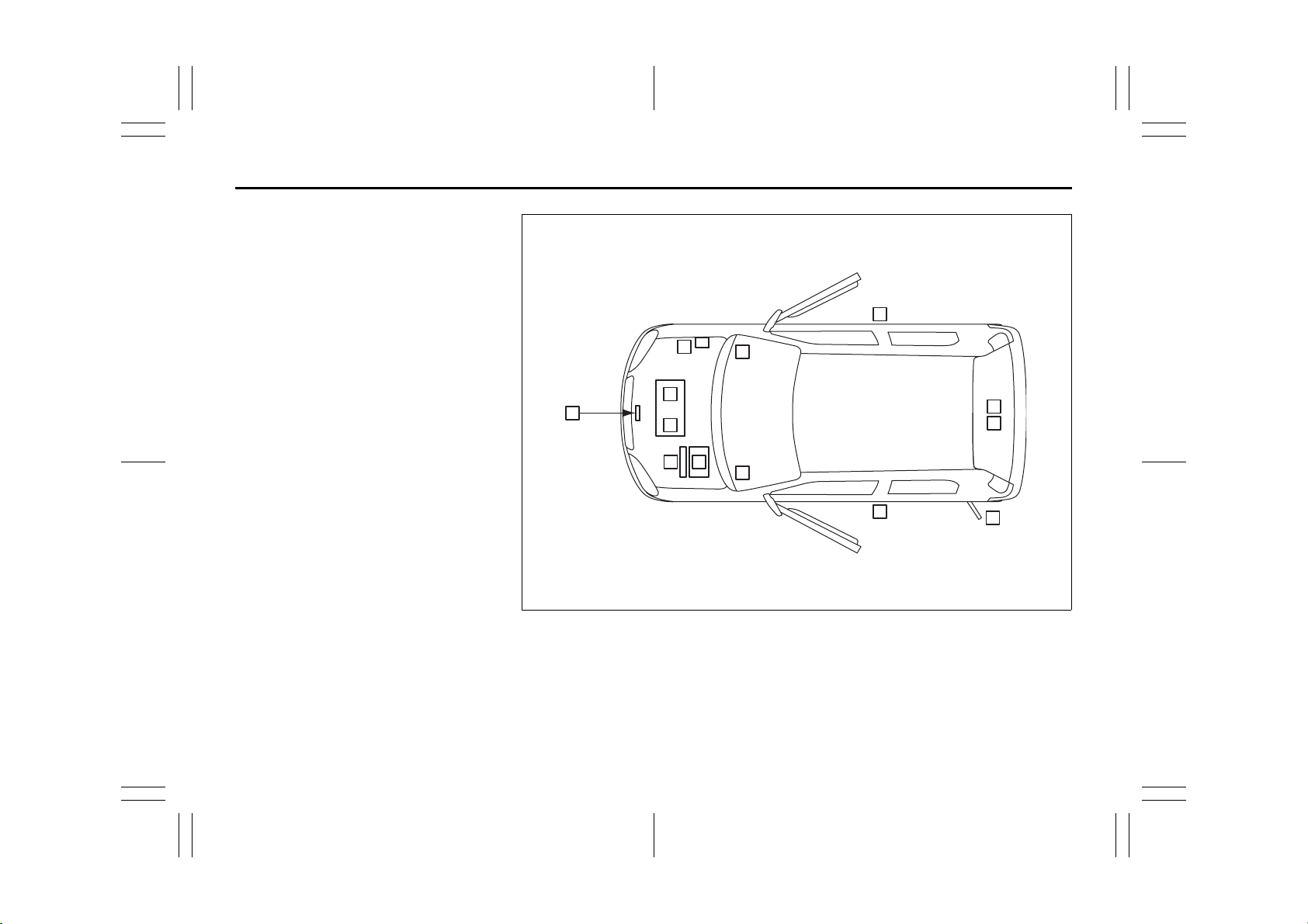
Your vehicle is equipped with a Supplemental Restraint System consisting of the
following components in addition to a lapshoulder belt at each front seating position.
1. Driver’s front air bag module
2. Front passenger’s front air bag module
3. Side air bag module (if equipped)
4. Side curtain air bag module
(if equipped)
5. Seat belt pretensioners
6. Air bag controller
7. Forward crash sensor
8. Side crash sensor (if equipped)
EXAMPLE
7
4
1
2
3
3
5
6
5
8
8
4
52KM034
2-37
51KM0-01E
Page 53

BEFORE DRIVING
63J030
If the “AIR BAG” light on the instrument
cluster does not blink when the ignition
switch is first turned to the “ON” position,
or the “AIR BAG” light stays on, or comes
on while driving, the air bag system (or the
seat belt pretensioner system (if
equipped)) may not work properly. Have
the air bag system inspected by an authorized SUZUKI dealer as soon as possible.
Front Air Bags
EXAMPLE
63J259
EXAMPLE
52KM035
The driver’s front air bag is located behind
the center pad of the steering wheel and
the front passenger’s front air bag is
located behind the passenger’s side of the
dashboard. The words “SRS AIRBAG” are
molded into the air bag covers to identify
the location of the air bags.
Frontal collision range
60G032
Front air bags will not inflate
65D236
2-38
51KM0-01E
Page 54

BEFORE DRIVING
Front air bags will probably not inflate
WARNING
An air bag supplements, or adds to,
the crash protection offered by seat
belts. The driver and all passengers
must be properly restrained by wearing seat belts at all times, whether or
not an air bag is mounted at their
seating position, to minimize the risk
of severe injury or death in the event
of a crash.
65D237
Front air bags are designed to inflate only
in severe frontal collisions. They are not
designed to inflate in rear impacts, side
impacts, rollovers or minor frontal collisions, since they would offer no protection
in those types of accidents. Remember,
since an air bag deploys only one time during an accident, seat belts are needed to
restrain occupants from further movements during the accident.
Therefore, an air bag is NOT a substitute
for seat belts. To maximize your protection,
ALWAYS WEAR YOUR SEAT BELTS. Be
aware that no system can prevent all possible injuries that may occur in an accident.
2-39
65D607
WARNING
Do not install a rear-facing child
restraint in the front passenger’s seat
unless the front passenger’s front air
bag is deactivated. If the passenger’s
front air bag inflates, a child in a rearfacing child restraint could be killed
or severely injured. The back of a
rear-facing child restraint would be
too close to the inflating air bag.
If you must use a front-facing child restraint
in the front passenger’s seat, be sure to
move the front passenger’s seat as far
back as possible. Please refer to the “Seat
Belts and Child Restraint Systems” section
in this section for details on securing your
child.
51KM0-01E
Page 55

BEFORE DRIVING
Air bag symbol (if equipped)
EXAMPLE
ADVERTENCIA WARNUNG
ATTENZIONE WAARSCHUWING
VIGYÁZAT
GB
F
E
D
I
NL
H
DO NOT place rear-facing child seat
on this seat with airbag.
DEATH OR SERIOUS INJURY can
occur.
The BACK SEAT with child restraint
is the SAFEST place for children.
You may find this label on the sun visor.
AVERTISSEMENTWARNING
73K021
Side Air Bags and Side Curtain Air
Bags (if equipped)
EXAMPLE
62J114
EXAMPLE
52KM036
Side air bags (if equipped) are located in
the part of the front seatbacks closest to
the doors. The words “SRS AIRBAG” are
molded into the side air bag cover to identify the location of the side air bags.
WARNING
If your vehicle is equipped with side
air bags, do not install a child
restraint in the front passenger’s seat
unless the front passenger’s side air
bag is deactivated. If the passenger’s
side air bag inflates, a child in a child
restraint could be injured.
EXAMPLE
52KM131
Side curtain air bags (if equipped) are
located in the roof lining. The words “SRS
AIRBAG” are molded into the pillar to identify the location of the side curtain air bags.
2-40
51KM0-01E
Page 56

BEFORE DRIVING
Side collision range
54G026
Side air bags and side curtain air bags
will not inflate
54G027
Side air bags and side curtain air bags
will probably not inflate
54G028
Side air bags and side curtain air bags are
designed to inflate only in severe side
impact collisions. They are not designed to
inflate in frontal or rear collisions, rollovers
or minor side collisions, since they would
offer no protection in those types of accidents. Only the side air bag and side curtain air bag on the side of the vehicle that
is struck will inflate. Remember, since an
air bag deploys only one time during an
accident, seat belts are needed to restrain
occupants from further movements during
the accident.
Therefore, an air bag is NOT a substitute
for seat belts. To maximize your protection,
ALWAYS WEAR YOUR SEAT BELTS. Be
aware that no system can prevent all possible injuries that may occur in an accident.
WARNING
An air bag supplements, or adds to,
the crash protection offered by seat
belts. The driver and all passengers
must be properly restrained by wearing seat belts at all times, whether or
not an air bag is mounted at their
seating position, to minimize the risk
of severe injury or death in the event
of a crash.
NOTE:
The curtain air bags are not connected
with the front passenger’s air bags deactivation system (if equipped). Even if the
front passenger’s air bags are deactivated,
the curtain air bags are still activated.
2-41
51KM0-01E
Page 57

BEFORE DRIVING
How the system works
In a frontal collision, the crash sensors will
detect rapid deceleration, and if the controller judges that the deceleration represents a severe frontal crash, the controller
will trigger the inflators. If your vehicle is
equipped with side air bags and side curtain air bags, crash sensors will detect a
side collision, and if the controller judges
that the side collision is severe enough, it
will trigger a side inflator. The inflators
inflate the appropriate air bags with nitrogen or argon gas. The inflated air bags
provide a cushion for your head (front air
bags and side curtain air bags only) and
upper body. The air bag inflates and
deflates so quickly that you may not even
realize that it has activated. The air bag will
neither hinder your view nor make it harder
to exit the vehicle.
Air bags must inflate quickly and forcefully
in order to reduce the chance of serious or
fatal injuries. However, an unavoidable
consequence of the quick inflation is that
the air bag may irritate bare skin, such as
the facial area against a front air bag. Also,
upon inflation, a loud noise will occur and
some powder and smoke will be released.
These conditions are not harmful and do
not indicate a fire in the car. Be aware,
however, that some air bag components
may be hot for a while after inflation.
A seat belt helps keep you in the proper
position for maximum protection when an
air bag inflates. Adjust your seat as far
back as possible while still maintaining
control of the vehicle. Sit fully back in your
seat; sit up straight; do not lean over the
steering wheel or dashboard. Front occupants should not lean on or sleep against
the door. Please refer to the “Front Seat”
section and the “Seat Belts and Child
Restraint Systems” section in this section
for details on proper seat and seat belt
adjustments.
65D610
54G582
2-42
51KM0-01E
Page 58

BEFORE DRIVING
WARNING
• The driver should not lean over the
steering wheel. The front passenger should not rest his or her body
against the dashboard, or otherwise get too close to the dashboard. For vehicles with side air
bags and side curtain air bag,
occupants should not lean on or
sleep against the door. In these situations, the out-of-position occupant would be too close to an
inflating air bag, and may suffer
severe injury.
• Do not attach any objects to, or
place any objects over, the steering
wheel or dashboard. Do not place
any objects between the air bag
and the driver or front passenger.
These objects may interfere with air
bag operation or may be propelled
by the air bag in the event of a
crash. Either of these conditions
may cause severe injury.
• For vehicles with side air bags, do
not place seat covers on the front
seats, because seat covers could
restrict the air bag’s inflation. Also,
do not place any cup holders on
the door, as the cup holder could
be propelled by the air bag in the
event of a crash. Either of these
conditions may cause severe
injury.
Note that even though your vehicle may be
moderately damaged in a collision, the collision may not have been severe enough to
trigger the front or side air bags to inflate. If
your car sustains ANY front-end or side
damage, have the air bag system
inspected by an authorized SUZUKI dealer
to ensure it is in proper working order.
Your vehicle is equipped with a diagnostic
module which records information about
the air bag system if the air bags deploy in
a crash. The module records information
about overall system status, which sensors
activated the deployment.
Servicing the air bag system
If the air bags inflate, have the air bags and
related components replaced by an authorized SUZUKI dealer as soon as possible.
If your vehicle ever gets in deep water and
the driver’s floor is submerged, the air bag
controller could be damaged. If it does,
have the air bag system inspected by the
SUZUKI dealer as soon as possible.
Special procedures are required for servicing or replacing an air bag. For that reason,
only an authorized SUZUKI dealer should
be allowed to service or replace your air
bags. Please remind anyone who services
your SUZUKI that it has air bags.
Service on or around air bag components
or wiring must be performed only by an
authorized SUZUKI dealer. Improper service could result in unintended air bag
deployment or could render the air bag
inoperative. Either of these two conditions
may result in severe injury.
To prevent damage or unintended inflation
of the air bag system, be sure the battery
is disconnected and the ignition switch has
been in the “LOCK” position for at least 90
seconds before performing any electrical
service work on your SUZUKI. Do not
touch air bag system components or wires.
The wires are wrapped with yellow tape or
yellow tubing, and the couplers are yellow
for easy identification.
Scrapping a car that has an uninflated air
bag can be hazardous. Ask your dealer,
body repair shop or scrap yard for help
with disposal.
2-43
51KM0-01E
Page 59

BEFORE DRIVING
Front Passenger Air Bag Deactivation System (if equipped)
(1)
EXAMPLE
52KM037
(1) Front passenger air bag deactivation
control indicator
The front passenger’s front and side air
bag must be deactivated if a child restraint
system is to be installed in the front passenger’s seat.
When the ignition switch is in the “ON”
position, the air bag deactivation control
indicator (1) shows the front passenger air
bags operation.
The front passenger’s air bags are activated:
The air bag deactivation control indicator
(1) blinks several times, and then goes off.
The front passenger’s air bags are deactivated:
The air bag deactivation control indicator
(1) blinks several times, and then remains
on.
65D607
WARNING
Do not install a rear-facing child
restraint in the front passenger’s seat
unless the front passenger’s air bag
is deactivated. If the passenger’s air
bag inflates, a child in a child
restraint could be killed or seriously
injured. The back of a rear-facing
child restraint would be too close to
the inflating air bag.
WARNING
If your vehicle is equipped with side
air bags, do not install a child
restraint in the front passenger’s seat
unless the front passenger’s side air
bag is deactivated. If the front passenger’s side air bag inflates, a child
in a child restraint could be injured.
WARNING
Be sure to activate the front passenger air bags whenever the child
restraint is not installed in the front
passenger’s seat. If the front passenger’s air bags do not inflate in collisions, an occupant could be killed or
seriously injured.
According to accident statistics, children
are safer when properly restrained in rear
seating positions than in front seating positions. Whenever possible, SUZUKI recommends that child restraint systems be
installed on the rear seat.
2-44
51KM0-01E
Page 60

BEFORE DRIVING
Air bag deactivation switch
AIR BAG
ON
(2)
AIR BAG
OFF
EXAMPLE
51KM030
The air bag deactivation switch (2) is on
the lateral face of the passenger’s side of
the instrument panel. You can operate the
air bag deactivation switch (2) when the
ignition switch is in the “LOCK” position.
To deactivate the front passenger’s air
bags, follow the instructions below.
1) Turn the ignition switch to the “LOCK”
position and pull out the key.
2) Insert the key into the air bag deactivation switch (2), and then push and turn
the key to the “AIR BAG OFF” position.
3) Turn the ignition switch to the “ON”
position. The air bag deactivation control indicator (1) blinks several times,
and then remains on to remind you the
front passenger’s air bags are deactivated.
To activate the front passenger’s air bags,
follow the instructions below.
1) Turn the ignition switch to the “LOCK”
position and pull out the key.
2) Insert the key into the air bag deactivation switch (2), and then push and turn
the key to the “AIR BAG ON” position.
3) Turn the ignition switch to the “ON”
position. The air bag deactivation control indicator (1) blinks several times,
and then goes out to remind you the
front passenger’s air bags are activated.
NOTE:
You should operate the air bag deactivation switch (2) when the ignition switch is in
the “LOCK” position. If you operate the air
bag deactivation switch (2) when the ignition switch is in a position other than the
“LOCK”, the air bag deactivation control
indicator (1) blinks several times and the
operation cannot be switched. In that case,
do the above instruction all over again.
NOTE:
Side curtain air bags and seat belt pretantioners are not connected with the air bag
deactivation system. Even if the front passenger air bags are deactivated, side curtain air bags and seat belt pretensioners
are still activated.
2-45
51KM0-01E
Page 61

Instrument Cluster
1. Speedometer
2. Odometer/Trip meter
3. Odometer/Trip meter selector knob
4. Tachometer
5. Fuel gauge
6. Warning and indicator lights
BEFORE DRIVING
EXAMPLE
16 6 6 4
2 5 3
51KM017
2-46
51KM0-01E
Page 62

BEFORE DRIVING
Warning and Indicator Lights
Brake System Warning Light
65D477
For working check of this light, there are
following three different type operations
depending on the vehicle’s specification.
1) The light comes on briefly when the
ignition switch is turned to the “ON”
and/or “START” position.
2) The light comes on when the parking
brake is engaged with the ignition
switch in the “ON” position.
3) The light comes on when under either
or both of above two conditions.
The light also comes on when the fluid in
the brake fluid reservoir falls below the
specified level.
The light should go out after starting the
engine and fully releasing the parking
brake, if the fluid level in the brake fluid reservoir is adequate.
The light also comes on together with the
ABS warning light when the rear brake
force control function (Proportioning valve
function) of the ABS system fails.
If the brake system warning light comes on
while you are driving the vehicle, it may
mean that there is something wrong with
the vehicle’s brake system. If this happens,
you should:
1) Pull off the road and stop carefully.
WARNING
Remember that stopping distance
may be longer, you may have to push
harder on the pedal, and the pedal
may go down farther than normal.
2) Test the brakes by carefully starting and
stopping at the side of the road.
– If you determine that it is safe, drive
carefully at low speed to the nearest
dealer for repairs, or
– Have the vehicle towed to the nearest
dealer for repairs.
WARNING
If any of the following conditions
occur, you should immediately ask
your SUZUKI dealer to inspect the
brake system.
• If the brake system warning light
does not go out after the engine
has been started and the parking
brake has been fully released.
• If the brake system warning light
does not come on when the ignition switch is turned to the “ON” or
“START” position.
• If the brake system warning light
comes on at any time during vehicle operation.
NOTE:
Because the disc brake system is selfadjusting, the fluid level will drop as the
brake pads become worn. Replenishing
the brake fluid reservoir is considered normal periodic maintenance.
2-47
51KM0-01E
Page 63

BEFORE DRIVING
Seat Belt Warning Light
60G049
This light blinks as a reminder until the
driver’s seat belt is buckled.
For details about the seat belt reminder,
refer to “Seat Belts and Child Restraint
Systems” in this section.
“AIR BAG” Light
63J030
This light blinks or comes on for several
seconds when the ignition switch is turned
to the “ON” position so you can check if the
light is working.
The light will come on and stay on if there
is a problem in the air bag system or the
seat belt pretensioner system.
WARNING
If the “AIR BAG” light does not blink
or come on briefly when the ignition
switch is turned to the “ON” position,
stays on for more than 10 seconds,
or comes on while driving, the air bag
system or the seat belt pretensioner
system may not work properly. Have
both systems inspected by an authorized SUZUKI dealer.
Low Fuel Warning Light
54G343
If this light comes on, fill the fuel tank
immediately.
NOTE:
The activation point of this light varies
depending on road conditions (for example, slope or curve) and driving conditions
because of fuel moving in the tank.
2-48
51KM0-01E
Page 64

BEFORE DRIVING
Anti-Lock Brake System (ABS)
Warning Light
65D529
When the ignition switch is turned to the
“ON” position, the light comes on briefly so
you can check that the light is working.
If the light stays on, or comes on when
driving, there may be something wrong
with the ABS.
If this happens:
1) Pull off the road and stop carefully.
2) Turn the ignition switch to “LOCK” and
then start the engine again.
If the warning light comes on briefly then
turns off, the system is normal. If the warning light still stays on, the system will be
something wrong.
If the light and the brake system warning
light stay on, or come on simultaneously
when driving, your ABS system is
equipped with the rear brake force control
function (Proportioning valve function) and
there may be something wrong with both
the rear brake force control function and
anti-lock function of the ABS system.
If one of these happens, have the system
inspected by your SUZUKI dealer.
If the ABS becomes inoperative, the brake
system will function as an ordinary brake
system that does not have this ABS system.
“ESP” (Electronic Stability
Program) Warning Light
(if equipped)
66J031
When the ignition switch is turned to the
“ON” position, the light comes on briefly so
you can check that the light is working. If
the light stays on, or comes on when driving, there may be something wrong with
the ESP
should have the system inspected by an
authorized SUZUKI dealer.
For details of the ESP
“Electronic Stability Program (ESP
the “OPERATING YOUR VEHICLE” section.
®
systems (other than ABS). You
®
systems, refer to
®
)” in
Malfunction Indicator Light
63J031
Your vehicle has a computer-controlled
emission control system. A malfunction
indicator light is provided on the instrument
panel to indicate when it is necessary to
have the emission control system serviced.
The malfunction indicator light comes on
when the ignition switch is turned to “ON”
or “START” and goes out when the engine
is started.
If the malfunction indicator light comes on
when the engine is running, there is a
problem with the emission control system.
Bring the vehicle to your SUZUKI dealer to
have the problem corrected.
CAUTION
Continuing to drive the vehicle when
the malfunction indicator light is on
can cause permanent damage to the
vehicle’s emission control system,
and can affect fuel economy and
driveability.
2-49
51KM0-01E
Page 65

BEFORE DRIVING
Electric Power Steering Light
(if equipped)
79J039
This light comes on when the ignition
switch is turned to the “ON” position, and
goes out when the engine is started.
If this light comes on while driving, the
power steering system may not work properly. Have the system inspected by your
SUZUKI dealer.
NOTE:
If the power steering system does not work
properly, you will feel heavier to steer but
you still will be able to steer.
Oil Pressure Light
50G051
This light comes on when the ignition
switch is turned to the “ON” position, and
goes out when the engine is started. The
light will come on and remain on if there is
insufficient oil pressure. If the light comes
on when driving, pull off the road as soon
as you can and stop the engine.
Check the oil level and add oil if necessary.
If there is enough oil, the lubrication system should be inspected by your SUZUKI
dealer before you drive the vehicle again.
Oil Life Monitoring
(For Diesel Engine Model with DPF
If this light blinks when the engine is running, you should change the engine oil. For
details on how to change the engine oil,
refer to “Changing Engine Oil and Filter” in
“INSPECTION AND MAINTENANCE” section.
Whenever the engine oil is changed, the
light must be reset to monitor the next oil
change timing properly. To reset the light,
see your SUZUKI dealer.
®
)
CAUTION
• If you operate the engine with this
light on, severe engine damage can
result.
• Do not rely on the Oil Pressure
Light to indicate the need to add
oil. Be sure to periodically check
the engine oil level.
Charging Light
50G052
This light comes on when the ignition
switch is turned to the “ON” position, and
goes out when the engine is started. The
light will come on and remain on if there is
something wrong with the battery charging
system. If the light comes on when the
engine is running, the charging system
should be inspected immediately by your
SUZUKI dealer.
2-50
51KM0-01E
Page 66

BEFORE DRIVING
High Engine Coolant Temperature
Warning Light (red color)
54G344
When the ignition switch is turned to the
“ON” position, this light comes on briefly so
you can check that the light is working. If
this light blinks while driving, it means the
engine is running hot. Avoid driving conditions that may lead to actual overheating. If
the light stays on without blinking, then the
engine is overheating. Follow the instructions in the “If the Engine Overheats” of
“EMERGENCY SERVICE” section.
CAUTION
Continuing to drive the vehicle when
engine overheating is indicated can
result in severe engine damage.
Transaxle Warning Light
(if equipped)
81A262
This light comes on for several seconds
when the ignition switch is turned to the
“ON” position so you can check the light is
working. If this light blinks, there is the
problem with the transaxle system. Ask
your SUZUKI dealer to have the system
inspected.
Immobilizer System Light
(if equipped)
65D239
This light comes on when the ignition
switch is turned to the “ON” position, and
goes out when the engine is started. If this
light blinks with the ignition switch turned to
“ON”, there may be something wrong with
the immobilizer system. Ask your SUZUKI
dealer to have the system inspected.
Service Vehicle Soon (SVS) Light
(For Diesel Engine Model)
84E034
When the ignition switch is turned to the
“ON” position, this light comes on briefly to
let you know the light is working.
If this light comes on when the engine is
running, there may be something wrong
with the engine electronics system. Ask
your SUZUKI dealer to have the system
inspected.
If this light blinks with the ignition switch
turned “ON”, there may be something
wrong with the immobilizer system. Ask
your SUZUKI dealer to have the system
inspected.
2-51
51KM0-01E
Page 67

BEFORE DRIVING
Glow Plug Indicator Light
(For Diesel Engine Model)
60A543
If the coolant temperature is cool enough,
this light comes on when the ignition switch
is turned on and goes out when the glow
plug is heated enough for engine starting.
Diesel Particulate Filter (DPF®)
Warning Light (For Diesel Engine
Model) (if equipped)
64J244
This light comes on for several seconds
when the ignition switch is turned to the
“ON” position so you can check the light is
working. If the light comes on when driving, the DPF
erate the DPF
drive the vehicle until the light goes out, at
an average speed of 75 km/h (47 mph) for
about 30 minutes.
When the regeneration of the diesel particulate filter is completed by your driving, the
®
DPF
For details of the DPF
Particulate Filter” in the “OPERATING
YOUR VEHICLE” section.
®
is nearly clogged. To regen-
®
, we recommend that you
warning light will go out.
®
, refer to “Diesel
Open Door Warning Light
(if equipped)
54G391
This light remains on until all doors (including the tailgate) are completely closed.
Turn Signal Indicators
50G055
When you turn on the left or right turn signals, the corresponding green arrow on the
instrument panel will flash along with the
respective turn signal lights. When you
turn on the hazard warning switch, both
arrows will flash along with all of the turn
signal lights.
2-52
51KM0-01E
Page 68

BEFORE DRIVING
Main Beam (high beam) Indicator
Light
50G056
This indicator comes on when headlight
main beams (high beams) are turned on.
“TCSS OFF” Indicator Light
(if equipped)
52KM132
When the ignition switch is turned to the
“ON” position, this light comes on briefly so
you can check that the light is working.
When the “TCSS OFF” switch is pushed to
turn off the traction control system, the
“TCSS OFF” light comes on and stays on.
NOTE:
If the traction control system operates continuously such as when driving on slippery
roads, the traction control system may be
canceled temporarily to avoid overheating
the brake pads, and the light will come on.
After a short period of time, the traction
control system will turn on automatically
and the light will go out.
For details of the traction control system,
refer to “Electronic Stability Program
®
(ESP
)” in the “OPERATING YOUR VEHI-
CLE” section.
SLIP Indicator Light (if equipped)
52KM133
ESP® is a registered trademark of
DaimlerChrysler AG.
This light blinks 5 times per second when
one of the ESP
is activated. If this light blinks, drive carefully.
When the ignition switch is turned to the
“ON” position, the light comes on briefly so
you can check that the light is working. If
the light stays on, or comes on when driving and remains on, there may be something wrong with the ESP
than ABS). You should have the system
®
systems other than ABS
®
systems (other
inspected by an authorized SUZUKI
dealer.
NOTE:
When you disconnect and re-connect the
battery, ESP
®
system functions other than
ABS will be deactivated and the slip indicator light will blink 1 time per second. For
details on how to reactive the ESP
®
systems, refer to “SLIP Indicator Light” in the
“OPERATING YOUR VEHICLE” section.
For details of the ESP® systems, refer to
“Electronic Stability Program (ESP®)” in
the “OPERATING YOUR VEHICLE” section.
WARNING
The ESP® systems cannot prevent
accidents. Always drive carefully.
Rear Fog Light Indicator Light
54G491
The rear fog light indicator light comes on
when the rear fog light operates.
2-53
51KM0-01E
Page 69

BEFORE DRIVING
Transaxle Selector Position
Indicator (if equipped)
51KM018
When the ignition switch is in the “ON”
position, the indicator shows the selector
position of automatic transaxle.
Speedometer/Odometer/Trip
meter/Meter Illumination
Control
EXAMPLE
(1) (2) (3)
51KM019
(1) Speedometer
(2) Display
(3) “MODE” knob
Speedometer
The speedometer indicates vehicle speed
in km/h.
Odometer/Trip meter
The odometer/trip meter is shown when
the ignition switch is in the “ON” position.
The odometer records the total distance
the vehicle has been driven. The trip meter
can be used to measure the distance traveled on short trips or between fuel stops.
NOTE:
When the ignition switch is turned to “ON”,
the display (2) shows the latest display that
the ignition switch was turned to “OFF” last
time.
CAUTION
Keep track of your odometer reading
and check the maintenance schedule
regularly for required services.
Increased wear or damage to certain
parts can result from failure to perform required services at the proper
mileage intervals.
2-54
51KM0-01E
Page 70

BEFORE DRIVING
(a)
Meter illumination control
(b)
(c)
(3)
(d)
(e)
(f)
52KM042
When the ignition switch is turned to “ON”,
the display shows three or six types of indication; odometer (a), trip meter A (b), trip
meter B (c), and if your vehicle is equipped
with the information display, instantaneous
fuel consumption (d), average fuel consumption (e), and driving range (f). Push
the “MODE” knob (3) quickly to switch the
indication among three or six. For the indication (d), (e), or (f), refer to “Information
Display” in “OTHER CONTROLS AND
EQUIPMENT” section for details.
(3)
About 2 seconds
52KM043
To reset the trip meter to zero, hold the
“MODE” knob (3) for more than 2 seconds
when the display (2) shows the indication
of trip meter (b) or (c).
(Brightest)
(3)
(Dimmest)
81A263
When the display shows the indication of
Trip meter B (c) or driving range (f) if your
vehicle is equipped with the information
display and the headlights are on, you can
change the indication to illumination intensity by pushing the “MODE” knob (3).
To change the meter illumination brightness, push and hold in the “MODE” knob
(3). The indication will change as shown in
the illustration. The illumination gets dimmer then returns to the brightest condition
after it reaches the dimmest.
2-55
51KM0-01E
Page 71

BEFORE DRIVING
Tachometer (if equipped)
EXAMPLE
51KM020
The tachometer indicates engine speed in
revolutions per minute.
CAUTION
Never drive with the engine speed
indicator in the red zone or severe
engine damage can result.
When downshifting to a lower gear,
make sure not to operate with excessive revolution speeds of the engine.
Refer to “Downshifting maximum
allowable speeds” in the “OPERATING YOUR VEHICLE” section.
Fuel Gauge
EXAMPLE
(2)
(1)
52KM045
When the ignition switch is in the “ON”
position, this gauge gives an approximate
indication of the amount of fuel in the fuel
tank. “F” stands for full and “E” stands for
empty.
If the fuel meter indicator shows only one
segment to “E”, refill the tank as soon as
possible.
If the low fuel warning light (1) comes on,
fill the fuel tank immediately.
The mark (2) indicates that the fuel filler
door is located on the left side of the vehicle.
NOTE:
The activation point of the low fuel warning
light (1) varies depending on road conditions (for example, slope or curve) and
driving conditions because of fuel moving
in the tank.
2-56
51KM0-01E
Page 72

BEFORE DRIVING
Lighting Control Lever
WARNING
To avoid possible injury, do not operate controls by reaching through the
steering wheel.
65D611
Lighting Operation
EXAMPLE
62J029
To turn the lights on or off, twist the knob
on the end of the lever. There are three
positions: in the “OFF” position all lights
are off; in the middle position the front
parking lights, taillights, license plate light,
and instrument lights are on, but the headlights are off; in the third position the headlights come on in addition to the other
lights.
EXAMPLE
62J030
With the headlights on, push the lever forward to switch to the high beams (main
beams) or pull the lever toward you to
switch to the low beams. When the high
beams (main beams) are on, a light on the
instrument panel will come on. To momentarily activate the high beams (main
beams) as a passing signal, pull the lever
slightly toward you and release it when you
have completed the signal.
2-57
51KM0-01E
Page 73

BEFORE DRIVING
Day time running light control
(if equipped)
When the engine is started, this system
turns on all lights. But this control is canceled when the light control lever is turned
to any position other than “OFF”.
Lights “On” reminder (if equipped)
A buzzer/chime sounds to remind you to
turn off the lights if they are left on when
the ignition key is removed and the driver’s
door is opened.
Front Fog Light Switch
(if equipped)
EXAMPLE
52KM046
The front fog light comes on when the fog
light switch is pushed in with the head light
switch turned to the second and/or third
position. An indicator light above the switch
will be lit when the front fog light is on.
NOTE:
In some countries the lighting operation
may be different from the above description according to local regulations.
Rear Fog Light Switch
(if equipped)
EXAMPLE
62J031
To turn the rear fog light on, twist the knob
as shown in the illustration with the head
light switch in the third position. When the
rear fog light is on, an indicator light on the
instrument cluster will come on. Do not
turn the rear fog light switch unless the
head light switch is in the third position.
NOTE:
When the head light switch is returned to
the “OFF” position, the rear fog light switch
will be cancelled automatically.
2-58
51KM0-01E
Page 74

BEFORE DRIVING
Headlight Leveling Switch
(if equipped)
EXAMPLE
52KM047
Level the headlight beam according to the
load condition of your vehicle by turning
this switch. The chart below shows the
appropriate switch position for different
vehicle-load conditions.
Vehicle Load Condition
Driver only 0
Driver + 1 passenger
(in front seat)
Driver + 4 passengers,
no cargo
Driver + 4 passengers,
cargo added
Driver + full cargo 4
Switch
Position
Turn Signal Control Lever
Turn Signal Operation
With the ignition switch in the “ON” position, move the lever up or down to activate
0
2
3
the right or left turn signals.
Normal turn signal
EXAMPLE
62J032
Move the lever all the way upward or downward to signal. When the turn is completed, the signal will cancel and the lever
will return to its normal position.
2-59
51KM0-01E
Page 75

BEFORE DRIVING
Lane change signal
EXAMPLE
62J033
Some times, such as when changing
lanes, the steering wheel is not turned far
enough to cancel the turn signal. For convenience, you can flash the turn signal by
moving the lever part way and holding it
there. The lever will return to its normal
position when you release it.
Hazard Warning Switch
EXAMPLE
52KM048
Push in the hazard warning switch to activate the hazard warning lights. All turn signal lights and both turn signal indicators
will flash simultaneously. To turn off the
lights, push the switch again.
Use the hazard warning lights to warn
other traffic during emergency parking or
when your vehicle could otherwise become
a traffic hazard.
Windshield Wiper and Washer
Lever
Windshield Wipers
EXAMPLE
MIST
OFF
INT
LO
HI
52KM049
To turn the windshield wipers on, move the
lever down to one of the three operating
positions. In the “INT” position (if
equipped), the wipers operate intermittently. The “INT” position is very convenient
for driving in mist or light rain. In the “LO”
position, the wipers operate at a steady
low speed. In the “HI” position, the wipers
operate at a steady high speed. To turn off
the wipers, move the lever back to the
“OFF” position.
Move the lever up and hold it to the “MIST”
position, the windshield wipers will turn on
continuously at low speed.
2-60
51KM0-01E
Page 76

BEFORE DRIVING
EXAMPLE
63J284
If the lever is equipped with the “INT TIME”
control, turn the control forward or rearward to adjust the intermittent wiper operation to the desired interval.
Windshield Washer
EXAMPLE
52KM050
To spray windshield washer fluid, pull the
lever toward you. The windshield wipers
will automatically turn on at low speed if
they are not already on and the “INT” position is equipped.
WARNING
• To prevent windshield icing in cold
weather, turn on the defroster to
heat the windshield before and during windshield washer use.
• Do not use radiator antifreeze in
the windshield washer reservoir. It
can severely impair visibility when
sprayed on the windshield, and can
also damage your vehicle’s paint.
CAUTION
To help prevent damage to the windshield wiper and washer system
components, you should take the following precautions:
• Do not continue to hold in the lever
when there is no windshield
washer fluid being sprayed or the
washer motor can be damaged.
• Do not attempt to remove dirt from
a dry windshield with the wipers or
you can damage the windshield
and the wiper blades. Always wet
the windshield with washer fluid
before operating the wipers.
• Clear ice or packed snow from the
wiper blades before using the wipers.
• Check the washer fluid level regularly. Check it often when the
weather is bad.
• Only fill the washer fluid reservoir
3/4 full during cold weather to allow
room for expansion if the temperature falls low enough to freeze the
solution.
2-61
51KM0-01E
Page 77

BEFORE DRIVING
Rear Window Wiper/Washer
Switch (if equipped)
EXAMPLE
Wiper
Intermittent wiper
To turn the rear wiper on, twist the rear
wiper switch on the end of the lever forward to the “ON” position. If your vehicle is
equipped the “INT” position, the rear wiper
operates intermittently when you twist the
switch forward to the “INT” position. To turn
the rear wiper off, twist the switch rearward
to the “OFF” position.
With the rear wiper in the “OFF” position,
twist the switch rearward and hold it there
to spray window washer fluid.
With the rear wiper in the “ON” position,
turn the switch forward and hold it there to
spray window washer fluid.
Washer
52KM051
CAUTION
Clear ice or snow from the rear window and rear wiper blade before
using the rear wiper. Accumulated ice
or snow could prevent the wiper
blade from moving, causing damage
to the wiper motor.
Tilt Steering Lock Lever
(if equipped)
EXAMPLE
LOCK UNLOCK
63J026
The lock lever is located under the steering
column. To adjust the steering wheel
height:
1) Pull up the lock lever to unlock the
steering column.
2) Adjust the steering wheel to the desired
height and lock the steering column by
push down the lock lever.
3) Try moving the steering wheel up and
down to make sure it is securely locked
in position.
2-62
51KM0-01E
Page 78

BEFORE DRIVING
WARNING
Never attempt to adjust the steering
wheel height while the vehicle is
moving or you could lose control of
the vehicle.
Horn
EXAMPLE
79J060
Press the horn button of the steering wheel
to sound the horn. The horn will sound with
the ignition switch in any position.
2-63
51KM0-01E
Page 79

60G408
OPERATING YOUR VEHICLE
OPERATING YOUR VEHICLE
Exhaust Gas Warning ......................................................... 3-1
Daily Inspection Checklist .................................................. 3-1
Engine Oil Consumption .................................................... 3-2
Ignition Switch ..................................................................... 3-3
Parking Brake Lever ........................................................... 3-5
Pedal ..................................................................................... 3-6
Starting the Engine ............................................................. 3-7
Using the Transaxle ............................................................ 3-9
If You Can Not Shift Automatic Transaxle Gearshift
Lever Out of “P” (PARK) .................................................... 3-11
Braking ................................................................................. 3-12
Electronic Stability Program (ESP
®
) (if equipped) ........... 3-15
3
51KM0-01E
Page 80

Ignition Switch: 8
OPERATING YOUR VEHICLE
Exhaust Gas Warning
WARNING
Avoid breathing exhaust gases.
Exhaust gases contain carbon monoxide, a potentially lethal gas that is
colorless and odorless. Since carbon
monoxide is difficult to detect by
itself, be sure to take the following
precautions to help prevent carbon
monoxide from entering your vehicle.
• Do not leave the engine running in
garages or other confined areas.
(Continued)
52D334
WARNING
(Continued)
• Do not park with the engine running for a long period of time, even
in an open area. If it is necessary to
sit for a short time in a parked vehicle with the engine running, make
sure the air intake selector is set to
“FRESH AIR” and the fan is at high
speed.
• Avoid operating the vehicle with
the tailgate or trunk open. If it is
necessary to operate the vehicle
with the tailgate or trunk open,
make sure the sunroof (if equipped)
and all windows are closed, and the
blower is at high speed with the air
intake selector set to “FRESH AIR”.
• To allow proper operation of your
vehicle’s ventilation system, keep
the air inlet grille in front of the
windshield clear of snow, leaves, or
other obstructions at all times.
• Keep the exhaust tailpipe area clear
of snow and other material to help
reduce the buildup of exhaust
gases under the vehicle. This is
particularly important when parked
in blizzard conditions.
• Have the exhaust system inspected
periodically for damage and leaks.
Any damage or leaks should be
repaired immediately.
Daily Inspection Checklist
Before Driving
60A187S
1) Make sure that windows, mirrors, lights,
and reflectors are clean and unobstructed.
2) Visually check the tires for the following
points:
– the depth of the tread groove
– abnormal wear, cracks and damage
– loose wheel bolts
– existence of foreign material such as
nails, stones, etc.
Refer to “Tires” in “INSPECTION AND
MAINTENANCE” section for details.
3) Look for fluid and oil leaks.
NOTE:
It is normal for water to drip from the air
conditioning system after use.
3-1
51KM0-01E
Page 81

Ignition Switch: 8
OPERATING YOUR VEHICLE
4) Make sure the hood is fully closed and
latched.
5) Check the headlights, turn signal lights,
brake lights and horn for proper operation.
6) Adjust the seat and adjustable head
restraint (if equipped).
7) Check the brake pedal and the parking
brake lever.
8) Adjust the mirrors.
9) Make sure that you and all passengers
have properly fastened your seat belts.
10)Make sure that all warning lights come
on as the key is turned to the “ON” or
“START” position.
11)Check all gauges.
12)Make sure that the BRAKE SYSTEM
WARNING light turns off when the
parking brake is released.
Once a week, or each time you fill your fuel
tank, perform the following under-hood
checks:
1) Engine oil level
2) Coolant level
3) Brake fluid level
4) Windshield washer fluid level
5) Battery solution level
6) Hood latch operation
Pull the hood release handle inside the
vehicle. Make sure that you cannot
open the hood all the way without
releasing the secondary latch. Be sure
to close the hood securely after checking for proper latch operation. See “All
latches, hinges & locks” of “CHASSIS
AND BODY” in the “Periodic Maintenance Schedule” in the “INSPECTION
AND MAINTENANCE” section for lubrication schedule.
WARNING
Make sure the hood is fully closed
and latched before driving. If it is not,
it can fly up unexpectedly during
driving, obstructing your view and
resulting in an accident.
Once a month, or each time you fill your
fuel tank, check the tire pressure using a
tire pressure gauge. Also check the tire
pressure of the spare tire.
Engine Oil Consumption
It is normal for the engine to consume
some engine oil during normal vehicle
operation.
The amount of engine oil consumed
depends on the viscosity of the oil, the
quality of the oil and the conditions the
vehicle is driven under.
More oil is consumed during high-speed
driving and when there is frequent acceleration and deceleration. Under high loads,
your engine also will consume more oil.
A new engine also consumes more oil,
since its pistons, piston rings and cylinder
walls have not yet become conditioned.
New engines reach the normal level of oil
consumption only after approximately 5000
km (3000 miles) driving.
Oil consumption:
Max. 1.0 L per 1000 km
(1 Qt. per 600 miles)
When judging the amount of oil consumption, note that the oil may become diluted
and make it difficult to accurately judge the
true oil level.
As an example, if a vehicle is used for
repeated short trips, and consumes a normal amount of oil, the dipstick may not
show any drop in the oil level at all, even
after 1000 km (600 miles) or more of driving. This is because the oil is gradually
becoming diluted with fuel or moisture,
3-2
51KM0-01E
Page 82

Lighting/Turn Signal Control Lever: 8
OPERATING YOUR VEHICLE
making it appear that the oil level has not
changed.
You should also be aware that the diluting
ingredients evaporate out when the vehicle
is subsequently driven at high speeds,
such as on an expressway, making it
appear that oil is excessively consumed
after high-speed driving.
Ignition Switch
WARNING
To avoid possible injury, do not operate controls by reaching through the
steering wheel.
65D611
EXAMPLE
52KM052
The ignition switch has the following four
positions:
LOCK
This is the normal parking position. It is the
only position in which the key can be
removed.
3-3
51KM0-01E
Page 83

Lighting/Turn Signal Control Lever: 8
Windshield Wiper and Washer Lever: 8
Turn to “LOCK”
Push
OPERATING YOUR VEHICLE
ACC
Accessories such as the radio can operate, but the engine is off.
ON
This is the normal operating position. All
electrical systems are on.
START
This is the position for starting the engine
using the starter motor. The key should be
released from this position as soon as the
engine starts.
60G033
You must push in the key to turn it to the
“LOCK” position. It locks the ignition, and
prevents normal use of the steering wheel
after the key is removed.
If your vehicle is equipped with the automatic transaxle key inter lock system, the
key can be turned to the “LOCK” position
only when the gearshift lever is in the “P”
(Park) position.
To release the steering lock, insert the key
and turn it clockwise to one of the other
positions. If you have trouble turning the
key to unlock the steering, try turning the
steering wheel slightly to the right or left
while turning the key.
81A297S
WARNING
• Never remove the ignition key while
the vehicle is moving. The steering
wheel will lock and you will not be
able to steer the vehicle.
• Always remove the ignition key
when leaving the vehicle even if a
short time. Also do not leave children alone in a parked vehicle.
Unattended children could cause
accidental movement of the vehicle
or could tamper with power windows or power sunroof. They also
could suffer from heat stroke in
warm or hot weather. These could
result in severe injury or even
death.
3-4
51KM0-01E
Page 84

Windshield Wiper and Washer Lever: 8
Rear Window Wiper/Washer Switch: 8
OPERATING YOUR VEHICLE
CAUTION
• Do not use the starter motor for
more than 15 seconds at a time. If
the engine does not start, wait 15
seconds before trying again. If the
engine does not start after several
attempts, check the fuel and ignition systems or consult your
SUZUKI dealer.
• Do not leave the ignition switch in
the “ON” position if the engine is
not running as the battery will discharge.
Parking Brake Lever
EXAMPLE
(1)
(2)
(3)
62J100
(1) To set
(2) To release
(3) To release
The parking brake lever is located between
the seats. To set the parking brake, hold
the brake pedal down and pull the parking
brake lever all the way up. To release the
parking brake, hold the brake pedal down,
pull up slightly on the parking brake lever,
push the button on the end of the lever with
your thumb, and lower the lever to its original position.
For automatic transaxle vehicles, always
set the parking brake before moving the
gearshift lever to the “P” (PARK) position. If
you park on an incline and shift into “P”
before setting the parking brake, the
weight of the vehicle may make it difficult to
shift out of “P” when you are ready to drive
the vehicle.
When preparing to drive the vehicle, move
the gearshift lever out of the “P” position
before releasing the parking brake.
WARNING
• Never drive your vehicle with the
parking brake on: rear brake effectiveness can be reduced from overheating, brake life may be
shortened, or permanent brake
damage may result.
• If the parking brake does not hold
the vehicle securely or does not
fully release, have your vehicle
inspected immediately by an authorized SUZUKI dealer.
3-5
51KM0-01E
Page 85

Rear Window Wiper/Washer Switch: 8
Tilt Steering Lock Lever: 6
OPERATING YOUR VEHICLE
WARNING
Always set the parking brake fully
before leaving your vehicle or it may
move, causing injury or damage.
When parking, make sure the gearshift lever for manual transaxle vehicles is in 1st gear or “R” (Reverse)
and the gearshift lever for automatic
transaxle vehicles is in “P” (Park).
Remember, even though the transaxle is in gear or in Park, you must
set the parking brake fully.
WARNING
When parking the vehicle in
extremely cold weather, the following
procedure should be used:
1) Set the parking brake.
2) Shift the manual transaxle into
reverse or first gear, or the automatic transaxle into “P” (Park).
3) With the engine off, get out of the
vehicle and put chocks under the
wheels.
4) Release the parking brake.
When you return to your vehicle,
you must remember to first set the
parking brake, then remove the
wheel chocks.
Pedal
Manual transaxle
EXAMPLE
(1) (2) (3)
Automatic transaxle
EXAMPLE
(2)
Clutch Pedal (1)
(For manual transaxle)
The clutch pedal is used to disengage the
drive to the wheels when starting the
engine, stopping, or shifting the gearshift
lever. Depressing the pedal disengages
the clutch.
CAUTION
Do not drive with your foot resting on
the clutch pedal. It could result in
excessive clutch wear, clutch damage, or unexpected loss of engine
braking.
63J182
(3)
64J083
3-6
51KM0-01E
Page 86

Horn: 6
Remote Audio Controls:
OPERATING YOUR VEHICLE
Brake Pedal (2)
Your SUZUKI vehicle is equipped with front
disc brakes and rear drum brakes.
Depressing the brake pedal applies both
sets of brakes.
You may hear occasional brake squeal
when you apply the brakes. This is a normal condition caused by environmental
factors such as cold, wet, snow, etc.
WARNING
If brake squeal is excessive and
occurs each time the brakes are
applied, you should have the brakes
checked by your SUZUKI dealer.
WARNING
Do not “ride” the brakes by applying
them continuously or resting your
foot on the pedal. This will result in
overheating of the brakes which
could cause unpredictable braking
action, longer stopping distances, or
permanent brake damage.
Accelerator Pedal (3)
This pedal controls the speed of the
engine. Depressing the accelerator pedal
increases power output and speed.
Starting the Engine
Before Starting the Engine
52KM053
1) Make sure the parking brake is set fully.
2) Manual transaxle – Shift into “N” (Neutral) and depress the clutch pedal all
the way to the floor. Hold the clutch
pedal while starting the engine.
Automatic transaxle – If the gearshift
lever is not in “P” (Park) position, shift
into “P” (Park). (if you need to re-start
the engine while the vehicle is moving,
shift into “N”.)
NOTE:
Automatic transaxle vehicles have a starter
interlock device which is designed to keep
the starter from operating if the transaxle is
in any of the drive positions.
WARNING
Make sure that the parking brake is
set fully and the transaxle is in Neutral before attempting to start the
engine.
Starting a Cold and Warm Engine
(For Gasoline Engine Model)
With your foot off the accelerator pedal,
crank the engine by turning the ignition key
to “START”. Release the key when the
engine starts.
CAUTION
• Stop turning the starter immediately after the engine has started or
the starter system can be damaged.
• Do not crank the engine for more
than 15 seconds at a time. If the
engine doesn’t start on the first try,
wait about 15 seconds before trying again.
If the engine does not start after 15 seconds of cranking, wait about 15 seconds,
then press down the accelerator pedal to
1/3 of its travel and try cranking the engine
again. Release the key and accelerator
pedal when the engine starts.
3-7
51KM0-01E
Page 87

OPERATING YOUR VEHICLE
If the engine still does not start, try holding
the accelerator pedal all the way to the
floor while cranking. This should clear the
engine if it is flooded.
(For Diesel Engine Model)
Cold engine
Turn the ignition switch to the “ON” position
and wait until the glow plug indicator goes
out if it comes on. Crank the engine by
turning the ignition key to “START”.
Release the key when the engine starts.
CAUTION
• Stop turning the starter immediately after the engine has started or
the starter system can be damaged.
• Do not crank the engine for more
than 15 seconds at a time. If the
engine doesn’t start on the first try,
wait about 15 seconds before trying again.
Warm engine
Crank the engine by turning the ignition
key to “START”. Release the key when the
engine starts.
Caution when stopping the engine with
turbocharger
When stopping the engine after climbing or
high speed driving, let the engine idle for
about one minute or more (if it is not prohibited) to cool down the turbocharger and
engine oil. This is to prevent the engine oil
from over-deteriorating. Deteriorated
engine oil will damage the bearings of the
turbocharger.
Restarting D13A diesel engine after
fuel-empty stop
The engine stops and the malfunction indicator light comes on if the engine feels fuel
emptiness. To restart the engine, stop the
vehicles, hold the ignition key in “ON” position for 5–10 seconds to feed fuel, then
perform above engine starting procedure.
Have the indicator light turned off by your
SUZUKI dealer.
Diesel Particulate Filter (DPF®)
(For Diesel Engine) (if equipped)
DPF® warning light
64J244
If the DPF® warning light comes on when
driving, there is a risk of the particle filter
becoming clogged. You should regenerate
the DPF
comes on. To regenerate the DPF
recommend that you drive the vehicle until
®
when the DPF® warning light
®
, we
the light goes out, at an average speed of
75 km/h (47 mph) for about 30 minutes.
However, you should drive carefully with
keeping the legal speed limit, and take
care the surrounding traffic condition.
If you drive your vehicle at an average
speed of 75 km/h (47 mph) for about 30
minutes, the regeneration of the DPF
be completed and the DPF
®
warning light
®
will
will go out.
CAUTION
Be sure to regenerate the DPF® when
the DPF
Non-regenerate the DPF® will cause
the vehicle malfunction due to the
clogged filter.
NOTE:
When you drive your vehicle, the white
smoke may be emitted depending on the
grade of fuel used.
This is due to the particle filter being
regenerated automatically, and does not
affect the way the vehicle runs.
®
warning light comes on.
3-8
51KM0-01E
Page 88

OPERATING YOUR VEHICLE
Using the Transaxle
Manual Transaxle
52KM055
Starting off
To start off, depress the clutch pedal all the
way to the floor and shift into 1st gear.
After releasing the parking brake, gradually
release the clutch. When you hear a
change in the engine’s sound, slowly press
the accelerator while continuing to gradually release the clutch.
Shifting
All forward gears are synchronized, which
provides for quiet, and easy shifting.
Always push in the clutch pedal fully before
shifting gears.
Downshifting maximum allowable
speeds
For 1.0L engine
Downshifting Km/h (mph)
2nd to 1st 45 (28)
3rd to 2nd 80 (50)
4th to 3rd 120 (75)
5th to 4th 150 (93)*
For 1.2L engine
Downshifting Km/h (mph)
2nd to 1st 45 (28)
3rd to 2nd 85 (53)
4th to 3rd 130 (81)
5th to 4th 160 (99)*
For 1.25L Diesel engine
Downshifting Km/h (mph)
2nd to 1st 40 (25)
3rd to 2nd 70 (43)
4th to 3rd 115 (71)
5th to 4th 155 (96)*
NOTE:(*)
You may not accelerate to the maximum
allowable speed because of the driving situation and/or the vehicle condition.
CAUTION
When downshifting to a lower gear,
make sure not to operate with the
speed faster than the maximum
allowable speeds for the next lower
gear, or severe engine damage can
result.
51KM021
Keep the engine speed so it does not get
into the red zone of tachometer.
3-9
51KM0-01E
Page 89

OPERATING YOUR VEHICLE
WARNING
• Reduce your speed and downshift
to a lower gear before going down
a long or steep hill. A lower gear
will allow the engine to provide
braking. Avoid riding the brakes or
they may overheat, resulting in
brake failure.
• When driving on slippery roads, be
sure to slow down before downshifting. Excessive and or sudden
changes in engine speed may
cause loss of traction, which could
cause you to lose control.
• Make sure that the vehicle is completely stationary before you shift
into reverse.
CAUTION
• To help avoid clutch damage, do
not use the clutch pedal as a footrest while driving or use the clutch
to keep the vehicle stationary on a
slope. Depress the clutch fully
when shifting.
• When shifting or starting off, do not
race the engine. Racing the engine
can shorten engine life and affect
smooth shifting.
4-Speed Automatic Transaxle
52KM139
Gearshift lever
52KM140
WARNING
Always depress the brake pedal
before shifting from “P” (Park) (or
“N” (Neutral) if the vehicle is stationary) to a forward or reverse gear, to
help prevent the vehicle from moving
unexpectedly when you shift.
Use the gearshift lever positions as
described below:
P (Park)
Use this position to lock the transaxle
when the vehicle is parked or when starting the engine. Shift into Park only when
the vehicle is completely stationary.
3-10
51KM0-01E
Page 90

OPERATING YOUR VEHICLE
R (Reverse)
Use this position to reverse the vehicle
from stop. Make sure that vehicle is completely stationary before shifting into
Reverse.
N (Neutral)
Use this position for starting the engine if
the engine stalls and you need to restart it
while the vehicle is moving. You may also
shift into Neutral and depress the brake
pedal to hold the vehicle stationary during
idling.
D (Drive)
Use this position for all normal driving.
With the gearshift lever in “D” range you
can get an automatic downshift by pressing the accelerator pedal. The higher the
vehicle speed is, the more you need to
press the accelerator pedal to get a downshift.
3 (Low 3)
Use this position for driving on moderate
uphill and downhill gradients. The engine
braking effect on moderate downhills can
be used in this position. The transaxle
shifts up only to 3rd gear.
2 (Low 2)
Use this position to provide extra power
when climbing hills, or to provide engine
braking when going down hills.
L (Low 1)
Use this position to provide maximum
power when climbing steep hills or driving
through deep snow or mud, or to provide
maximum engine braking when going
down steep hills.
NOTE:
If you move the gearshift lever to a lower
gear while driving faster than the maximum
allowable speed for the lower gear, the
transaxle will not actually downshift until
your speed drops below the maximum
speed for the lower gear.
CAUTION
Be sure to take the following precautions to help avoid damage to the
automatic transaxle:
• Make sure that the vehicle is completely stationary before shifting
into “P” or “R”.
• Do not shift from “P” or “N” to “R”,
“D”, “3”, “2”, or “L” when the
engine is running above idle speed.
• Do not rev the engine with the transaxle in a drive position (“R”, “D”,
“3”, “2”, or “L”) and the front
wheels not moving.
• Do not use the accelerator to hold
the vehicle on a hill. Use the vehicle’s brakes.
If You Can Not Shift
Automatic Transaxle
Gearshift Lever Out of “P”
(PARK)
Left Hand Drive Vehicle
(1)
52KM057
Vehicles with an automatic transaxle have
an electrically operated park-lock feature.
If the vehicle’s battery is discharged, or
there is some other electrical failure, the
automatic transaxle cannot be shifted out
of Park in the normal way. Jump starting
may correct the condition. If not, follow the
procedure described below. This procedure will permit shifting the transaxle out of
Park.
1) Be sure the parking brake is firmly
applied.
3-11
51KM0-01E
Page 91

OPERATING YOUR VEHICLE
2) If the engine is running, stop the
engine.
3) Make sure the key is in the “ON” or
“ACC” position.
4) Remove the cover (1) over the button.
5) With pushing the release button by the
key or the flat end rod, shift the gearshift lever to the desired position.
This procedure is for emergency use only.
If repeated use of this procedure is necessary, or the procedure does not work as
described, take the vehicle to your dealer
for repair.
Right Hand Drive Vehicle
(1)
52KM143
Vehicles with an automatic transaxle have
an electrically operated park-lock feature.
If the vehicle’s battery is discharged, or
there is some other electrical failure, the
automatic transaxle cannot be shifted out
of Park in the normal way. Jump starting
may correct the condition. If not, follow the
procedure described below. This procedure will permit shifting the transaxle out of
Park.
1) Be sure the parking brake is firmly
applied.
2) If the engine is running, stop the
engine.
3) Make sure the key is in the “ON” or
“ACC” position.
4) With pushing the release button (1),
shift the gearshift lever to the desired
position.
This procedure is for emergency use only.
If repeated use of this procedure is necessary, or the procedure does not work as
described, take the vehicle to your dealer
for repair.
Braking
EXAMPLE
60G165S
The distance needed to bring any vehicle
to a halt increases with the speed of the
vehicle. The braking distance needed, for
example, at 60 km/h (37 mph) will be
approximately 4 times greater than the
braking distance needed at 30 km/h (19
mph). Start to brake the vehicle when there
is plenty of distance between your vehicle
and the stopping point, and slow down
gradually.
3-12
51KM0-01E
Page 92

OPERATING YOUR VEHICLE
WARNING
If water gets into the brake drums,
brake performance may become poor
and unpredictable.
After driving through water or washing the underside of the vehicle, test
the brakes while driving at a slow
speed to see if they have maintained
their normal effectiveness. If the
brakes are less effective than normal,
dry them by repeatedly applying the
brakes while driving slowly until the
brakes have regained their normal
effectiveness.
Power Assisted Brakes
Your vehicle has power assisted brakes. If
power assistance is lost due to a stalled
engine or other failures, the system is still
fully operational on reserve power and you
can bring the vehicle to a complete stop by
pressing the brake pedal once and holding
it down. The reserve power is partly used
up when you depress the brake pedal and
reduces each time the pedal is pressed.
Apply smooth and even pressure to the
pedal. Do not pump the pedal.
WARNING
Even without reserve power in the
brake system, you can still stop the
vehicle by pressing the brake pedal
harder than normally required. However, the stopping distance may be
longer.
Anti-Lock Brake System (ABS)
(if equipped)
ABS will help you avoid skidding by electronically controlling braking pressure. It
will also help you maintain steering control
when braking on slippery surfaces or when
braking hard.
The ABS works automatically, so you do
not need any special braking technique.
Just push the brake pedal down without
pumping. The ABS will operate whenever it
senses that the wheels are locking up. You
may feel the brake pedal moves a little
while the ABS is operating.
NOTE:
The ABS will not work if vehicle speed is
under about 6 km/h (4 mph).
WARNING
• On some types of loose surfaces
(such as gravel, snow-covered
roads, etc.) the stopping distance
required for an ABS-equipped vehicle may be slightly greater than for
a comparable vehicle with a conventional brake system. With a
conventional brake system, skidding tires are able to “plow” the
gravel or snow layer, shortening
the stopping distance, ABS minimizes this resistance effect. Allow
for extra stopping distance when
driving on loose surfaces.
• On regular paved roads, some drivers may be able to obtain slightly
shorter stopping distances with
conventional brake systems than
with ABS.
• In both of the above conditions,
ABS will still offer the advantage of
helping you maintain directional
control. However, remember that
ABS will not compensate for bad
road or weather conditions or poor
driver judgment. Use good judgment and do not drive faster than
conditions will safely allow.
3-13
51KM0-01E
Page 93

(1) (2)
52KM059
(1) ABS warning light
(2) Break system warning light
WARNING
• If the ABS warning light (1) on the
instrument panel comes on and
stays on while driving, there may
be a problem with the ABS system.
Ask your SUZUKI dealer to inspect
the ABS system immediately. If the
ABS system becomes inoperative,
the brake system will function as
an ordinary brake system that has
no ABS.
(Continued)
WARNING
(Continued)
• If the ABS warning light (1) and the
Brake system warning light (2) on
the instrument panel simultaneously stays on or comes on
when driving, both anti-lock function and rear brake force control
function (Proportioning valve function) of the ABS system may have
failed. If so, the rear wheels may
easily skid or the vehicle can even
spin in the worst case when braking on a slippery road or when hard
braking even on a dry paved road.
Ask your SUZUKI dealer to inspect
the ABS system immediately. Drive
carefully, avoiding hard braking as
much as possible.
OPERATING YOUR VEHICLE
How the ABS Works
A computer continuously monitors wheel
speed. The computer compares the
changes in wheel speed when braking. If
the wheels slow suddenly, indicating a
skidding situation, the computer will
change braking pressure several times
each second to prevent the wheels from
locking. When you start your vehicle after a
stop you may hear a momentary motor
noise as the system checks itself.
WARNING
The ABS may not work properly if
tires or wheels other than those
specified in the owner’s manual are
used. This is because the ABS works
by comparing changes in wheel
speed. When replacing tires or
wheels, use only the size and type
specified in this owner’s manual.
3-14
51KM0-01E
Page 94

OPERATING YOUR VEHICLE
Electronic Stability Program
(ESP®) (if equipped)
ESP® is a registered trademark of
DaimlerChrysler AG.
®
can-
®
®
-
The Electronic Stability Program (ESP
helps to control the vehicle during cornering if the vehicle is understeering or oversteering. It also assists you in maintaining
traction while accelerating on loose or slippery road surfaces. It does this by regulating the engine’s output, and by selectively
applying the brakes. In addition, ESP
helps to avoid skidding by controlling braking pressure.
WARNING
The ESP® cannot enhance the vehicle’s driving stability in all situations
and does not control your vehicle’s
entire braking system. The ESP
not prevent accidents, including
those resulting from excessive speed
in turns, or hydroplaning. Only a safe
and attentive driver can prevent accidents. The capabilities of an ESP
equipped vehicle must never be used
as a substitute for careful driving.
The ESP
®
has the following three systems:
Stability Control System
The vehicle stability control system helps
provide integrated control of systems such
as anti-lock brakes, traction control, engine
)
control, etc. This system automatically
controls the brakes and engine to help prevent the vehicle from skidding when cornering on a slippery road surface or when
turning the steering wheel abruptly.
Traction Control System
®
The traction control system automatically
helps prevent the spinning of wheels when
the vehicle is started or accelerated on
slippery road surfaces. The system operates only if it senses that some of the
wheels are spinning or beginning to lose
traction. When this happens, the system
operates the front or rear brakes and
reduces engine power to limit wheel spin.
NOTE:
You may hear a clicking sound in the
engine compartment for a few seconds
when you start the engine or just after the
vehicle begins to move. This means that
the above systems are in the self-check
mode. This sound does not indicate a malfunction.
Anti-Lock Braking System (ABS)
ABS will help you avoid skidding by electronically controlling braking pressure. It
will also help you maintain steering control
when braking on slippery surfaces or when
braking hard. The ABS works automatically, so you do not have to use any special
braking technique. Just push the brake
pedal down without pumping. The ABS will
operate whenever it senses that wheels
are locking up. You may feel the brake
pedal pulsate while the ABS is operating.
(For more information on ABS, see “Braking” in this section.)
NOTE:
If the ABS system is activated, you may
hear a clunking noise and/or feel pulsating
in the brake pedal. This is normal and indicates that the brake fluid pressure is being
controlled properly.
3-15
51KM0-01E
Page 95

OPERATING YOUR VEHICLE
WARNING
• The ESP® may not work properly if
tires or wheels other than those
specified in the Owner’s Manual are
used. When replacing tires or
wheels, use only the size and type
specified in this Owner’s Manual.
• The ESP
®
may not work properly if
tires are not inflated to the recommended tire inflation pressure.
• The ESP
tires are fitted with tire chains.
• The ESP
®
may not work properly if
®
may not work properly if
the tires are excessively worn. Be
sure to replace tires when the tread
wear indicators in the grooves
appear on the tread surface.
• The ESP
®
is not a substitute for
winter tires or tire chains on a snow
covered road.
WARNING
• The ESP® may not work properly if
engine related parts such as the
muffler are not equivalent to standard equipment or are extremely
deteriorated.
• Do not modify the vehicle’s suspension since the ESP
operate correctly.
®
may not
The ESP® indicator lights are described
below:
SLIP Indicator Light
52KM133
When one of the ESP® systems other than
ABS is activated, the SLIP indicator light in
the instrument cluster blinks 5 times per
second.
CAUTION
If the SLIP indicator light comes on
and stays on while driving, there may
be a malfunction of the ESP
tems (other than ABS). You should
have the systems inspected by an
authorized SUZUKI dealer.
NOTE:
When the SLIP indicator light comes on
and stays on while driving, indicating a
malfunction of the ESP
®
systems (other
than ABS), the brake system will function
as an ordinary ABS with no additional
®
ESP
functions.
®
sys-
NOTE:
When you disconnect and re-connect the
battery, ESP
®
system functions other than
ABS will be deactivated and the slip indicator light will blink 1 time per second. In this
case, use the following procedure to reactivate the ESP
®
systems:
1) Drive your vehicle straight ahead with-
out tire slippage at a speed greater than
approximately 15 km/h (9 mph) for a
few seconds.
2) The slip indicator light will go out and
the ESP
®
systems (other than ABS) will
be re-activated.
It may take more than few seconds before
the slip indicator light goes out depending
on the road surface condition.
“ESP” Warning Light
66J031
When the ESP® systems (other than ABS)
have a system malfunction, the “ESP”
warning light in the instrument cluster
comes on.
3-16
51KM0-01E
Page 96

OPERATING YOUR VEHICLE
CAUTION
If the “ESP” warning light comes on,
or stays on while driving, there may
be a malfunction of the ESP
®
systems (other than ABS). You should
have the systems inspected by an
authorized SUZUKI dealer.
NOTE:
When the “ESP” warning light comes on,
or stays on while driving, indicating a malfunction of the ESP
®
systems (other than
ABS), the brake system will function as an
ordinary ABS that has no additional ESP
functions.
“TCSS OFF” Indicator Light
52KM132
You should turn the traction control system
on during your ordinary driving, so that you
have the benefits of all of the ESP
tems.
It may be required to turn the traction control system off if your vehicle is stuck in
sand, mud, or snow, where wheel spin is
necessary.
®
sys-
“TCSS OFF” switch
EXAMPLE
®
When the “TCSS OFF” switch is pushed to
turn off the traction control system, the
“TCSS OFF” indicator light in the instrument cluster comes on.
When you have turned the traction control
system off, make sure to turn them back on
before resuming ordinary driving.
When you push the “TCSS OFF” switch
again, the “TCSS OFF” indicator light will
go out and all of the ESP
activated.
®
systems will be
NOTE:
If the traction control system operates continuously, such as when driving on slippery
roads, the traction control system may be
canceled temporarily to avoid overheating
the brake pads, and the “TCSS OFF” indicator light will come on. After a short
period of time, the traction control system
will turn on automatically and the “TCSS
OFF” indicator light will go out.
ABS Warning Light / Brake System
Warning Light
See “Braking” in this section.
52KM060
3-17
51KM0-01E
Page 97

60G409
DRIVING TIPS
DRIVING TIPS
Running-in ........................................................................... 4-1
Catalytic Converter ............................................................. 4-1
Improving Fuel Economy ................................................... 4-2
Highway Driving .................................................................. 4-3
Driving on Hills .................................................................... 4-3
Driving on Slippery Roads ................................................. 4-4
4
51KM0-01E
Page 98

Ignition Switch: 8
DRIVING TIPS
WARNING
• Wear Your Seat Belts at All Times.
Even though air bags are equipped
at the front seating positions, the
driver and all passengers should
be properly restrained at all times,
using the seat belts provided. Refer
to the “Seat Belts and Child
Restraint Systems” section for
instructions on proper use of the
seat belts.
• Never drive while under the influence of alcohol or other drugs.
Alcohol and drugs can seriously
impair your ability to drive safely,
greatly increasing the risk of injury
to yourself and others. You should
also avoid driving when you are
tired, sick, irritated, or under
stress.
52D078S
Running-in Catalytic Converter
CAUTION
The future performance and reliability of the engine depends on the care
and restraint exercised during its
early life. It is especially important to
observe the following precautions
during the initial 960 km (600 miles)
of vehicle operation.
• After starting, do not race the
engine. Warm it up gradually.
• Avoid prolonged vehicle operation
at a constant speed. Moving parts
will break in better if you vary your
speed.
• Start off from a stop slowly. Avoid
full throttle starts.
• Avoid hard braking, especially during the first 320 km (200 miles) of
driving.
• Do not drive slowly with the transaxle in a high gear.
• Drive the vehicle at moderate
engine speeds.
• Do not tow a trailer during the first
960 km (600 miles) of vehicle operation.
The purpose of the catalytic converter is to
minimize the amount of harmful pollutants
in your vehicle’s exhaust. Use of leaded
fuel in vehicles equipped with catalytic
converters is prohibited, because lead
deactivates the pollutant-reducing components of the catalyst system.
The converter is designed to last the life of
the vehicle under normal usage and when
unleaded fuel is used. No special maintenance is required on the converter. However, it is very important to keep the engine
properly tuned. Engine misfiring, which
can result from an improperly tuned
engine, may cause overheating of the catalyst. This may result in permanent heat
damage to the catalyst and other vehicle
components.
80G106
4-1
51KM0-01E
Page 99

Ignition Switch: 8
DRIVING TIPS
CAUTION
To minimize the possibility of catalyst
or other vehicle damage:
• Maintain the engine in the proper
operating condition.
• In the event of an engine malfunction, particularly one involving
engine misfire or other apparent
loss of performance, have the vehicle serviced promptly.
• Do not turn off the engine or interrupt the ignition when the transaxle
is in gear and the vehicle is in
motion.
• Do not try to start the engine by
pushing or towing the vehicle, or
coasting down a hill.
• Do not idle the engine with any
spark plug wires disconnected or
removed, such as during diagnostic testing.
• Do not idle the vehicle for prolonged periods if idling seems
rough or there are other malfunctions.
• Do not allow the fuel tank to get
near the empty level.
54G584S
WARNING
Be careful where you park and drive;
the catalytic converter and other
exhaust components can get very
hot. As with any vehicle, do not park
or operate this vehicle in areas where
combustible materials such as dry
grass or leaves can come in contact
with a hot exhaust system.
Improving Fuel Economy
The following instructions will help you
improve fuel economy.
Avoid excessive idling
If you are to wait for more than a minute
while you are parked, stop the engine and
start it again later. When warming up a
cold engine, allow the engine to idle until
the temperature gauge pointer comes up
to the “C” position (if the idling is not prohibited). In this position, the engine is sufficiently warm for starting off.
Avoid “fast” starts
Fast starts away from lights or stop signs
will consume fuel unnecessarily and
shorten engine life. Start off slowly.
Avoid unnecessary stops
Avoid unnecessary deceleration and stopping. Try to maintain a slow, steady speed
whenever possible. Slowing down and then
accelerating again uses more fuel.
Keep a steady cruising speed
Keep as constant a speed as road and traffic conditions will permit.
4-2
51KM0-01E
Page 100

Lighting/Turn Signal Control Lever: 8
DRIVING TIPS
Keep the air cleaner clean
EXAMPLE
60A183S
A dirty air cleaner will cause the carburetion system to supply too much fuel to the
engine for the amount of air being supplied. The result is waste of fuel due to
incomplete combustion.
Keep weight to a minimum
The heavier the load, the more fuel the
vehicle consumes. Take out any luggage
or cargo when it is not necessary.
Keep tire pressures correct
Underinflation of the tires can waste fuel
due to increased running resistance of the
tires. Keep your tires inflated to the correct
pressure shown on the label on the driver’s
side door or the driver’s door lock pillar.
Highway Driving
When driving at highway speeds, pay
attention to the following:
• Stopping distance progressively
increases with vehicle speed. Apply the
brakes far enough ahead of the stopping
point to allow for the extra stopping distance.
• On rainy days, “Hydroplaning” can occur.
“Hydroplaning” is the loss of direct contact between the road surface and the
vehicle’s tires due to a water film forming
between them. Steering or braking the
vehicle while “Hydroplaning” can be very
difficult, and loss of control can occur.
Keep speed down when the road surface
is wet.
• At high speeds, the vehicle may be
affected by side winds. Therefore,
reduce speed and be prepared for unexpected buffeting, which can occur at the
exits of tunnels, when passing by a cut of
a hill, or when being overtaken by large
vehicles, etc.
Driving on Hills
52KM061
• When climbing steep hills, the car may
begin to slow down and show a lack of
power. If this happens, you should shift
to a lower gear so that the engine will
again be operating in its normal power
range. Shift rapidly to prevent the car
from losing momentum.
• When driving down a hill, the engine
should be used for braking by shifting
into a lower gear.
4-3
51KM0-01E
 Loading...