Sure Heat CVS303 User Manual

LP/NATURAL GAS SAFETY PILOT KIT
MODEL: CVS-303
Supplemental Installation Instructions for use on Emberglow Natural Gas Vented Log Sets
FOR INFRARED BURNER SYSTEMS ONLY
NOTE: This kit is for Natural Gas and L.P. Gas applications. For L.P. or Propane Gas installation see separate instructions packaged with necessary hardware. (Do not use the Natural Gas orifice supplied with this kit on
L.P. or Propane Gas Installations as improper combustion will occur.
IMPORTANT
Read and follow all instructions carefully as these supplemental Pilot Assembly instructions are to be used in conjunction with the General Installation Instructions supplied with all Emberglow Natural Gas log sets.
PARTS LIST & ILLUSTRATION
Part No. |
Description |
Part No. |
Description |
Part No. |
Description |
|
1 |
Control Knob |
12 |
Pilot Orifice - Natural Gas |
|
3/8” Natural Gas Orifice - |
|
3 |
Gas Control Valve |
14 |
Pilot Supply Line Nut |
20a |
||
18” Small Center Hole |
||||||
5 |
Thermocouple Lead |
15 |
Heat Shield |
|
||
|
|
|||||
6 |
Pilot Gas Supply Line |
16 |
Lock Nut |
|
3/8” Natural Gas Orifice - |
|
7 |
Pilot Burner |
17 |
90 Degree Street Elbow |
20b |
||
24” & 30” Large Center Hole |
||||||
8 |
Pilot Bracket |
18 |
3” Pipe Nipple |
|
||
|
|
|||||
9 |
Sheet Metal Screw (1) |
19 |
3/8” Female Elbow (2) |
21 |
3/8 Flare to 3/8 NPT |
National Code requirements mandate the use of a Pilot Safety Valve on all L.P. or Propane gas applications. These regulations must be followed on all installations of this type.

SINGLE, DUAL & TOPSIDE SYSTEMS
(For Infrared Systems See Page 3)
|
BEFORE proceeding with these instructions |
|
verify the type of log set you have. Is it a DUAL |
|
BURNER Set (Models MO18NG, MO24NG, |
STOP |
SH18NG, SH24NG, CSO30NG) OR an |
page 3. |
|
|
INFRARED Set (Models GO18TIR or GO24TIR)? |
|
1. If a DUAL BURNER Set proceed with the |
|
instructions beginning below through |
|
2. If an INFRARED Set proceed with |
|
instructions starting on page 4 continuing |
|
through page 5. |
Installation of Natural Gas Pilot Valve
This Safety Pilot Kit contains a Control Valve certified by C.S.A., which provides a safe and convenient way to ignite your energy efficient gas log set.
Note: Use pipe compound on all male threads to seal joints. |
Figure 1 |
|
|
|
A.This Safety Pilot Kit contains a Natural Gas Orifice and L.P. Gas hardware. Instructions are packaged separately in this kit.
B.Attach the 3/8” Natural Gas Orifice (Part #20a or #20b) through the
Burner Pan to the Burner Bar using the 3/8” Locknut supplied only with Dual and Topside Burner log sets. When installing a single burner log set, a 3/8” locknut is not used. Be sure the small drill hole on the
3/8” Natural Gas Orifice is facing the gas control valve and the large |
|
Figure 2 |
|
hole is facing the burner pan. (See Figure 1 & 2) |
|
|
|
|
|
|
C.Connect a 3/8” female elbow (Part #19) to the Natural Gas Orifice.
(See Figure 3)
D.Connect the 3” Pipe Nipple (Part #18) to elbow. (See Figure 4)
E.Connect the second 3/8” female elbow (Part # 19) to the 3” Pipe Nipple.
(See Figure 5)
|
Figure 5 |
|
|
Figure 4 |
|
|
Figure 3 |
|
|
|
|
|
|
|
|
|
|
|
|
|
|
|
|

Installation of Natural Gas Pilot Valve (cont.)
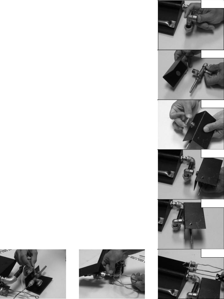
F.Connect the 90 degree street elbow (Part #17) to the 3/8” female elbow.
(See Figure 6)
G.Slide the hole in the heat shield (Part #15) over the 3/8” NPT threads on the Gas Control Valve (Part # 3). (See Figure 7)
H.Then secure the heat shield in place with the lock nut (Part # 16).
(See Figure 8)
I.Attach the control valve & heat shield assembly to the 90 degree street Elbow. (See Figures 9 & 10)
J.Attach the pilot bracket (Part # 8) to the burner pan using the sheet metal screw (Part # 9). (See Figure 11)
NOTE: The Pilot Bracket utilizes four mounting holes for adjustment
of the Pilot Burner Assembly should your installation require repositioning. Repositioning of the Pilot Burner Assembly may be necessary if the log set is experiencing intermittent shutdown. Shutdown is caused by overheating of the Pilot Burner Assembly by the main burner flame.
If shut down is occurring, move the Pilot Burner Assembly over to the next mounting hole so that only the tips of the Pilot Burner Assembly are hanging over the Burner Pan.
K.Carefully bend the Thermocouple lead (Part #5) and attach to the back of the control valve. (See Figure 12)
NOTE: When screwing into the Control Valve, hand tighten both the Pilot Gas supply line and Thermocouple Lead, then tighten 1/8 turn with a wrench. DO NOT OVER TIGHTEN as this will cause the Pilot to not function properly.
L.Attach pilot gas supply line (Part # 6) to the bottom of the gas control valve. Care should be taken not to kink the tubing which would restrict gas flow to the Pilot Burner. (See Figure 13)
|
Figure 13 |
|
|
Figure 12 |
|
|
|
|
|
|
|
|
|
|
Figure 6
Figure 7
Figure 8
Figure 9
Figure 10
Figure 11
 Loading...