


SURE HEAT
Installation and Operating Instructions for
NATURAL & L.P. GAS VENT FREE SYSTEM
Model: SCVFMR18, SCVFMR 24/21,
SCVFMR30 (LP or NG Versions)
DANGER:
FAILURE TO FOLLOW THESE INSTRUCTIONS CAREFULLY AND WITHOUT ERROR, OR FAILURE TO HEED ANY AND ALL WARNINGS IN THESE INSTRUCTIONS CAN RESULT IN AN EXPLOSION, FIRE OR THE PRODUCTION OF CARBON MONOXIDE GAS WHICH CAN CAUSE PROPERTY DAMAGE, BODILY INJURY OR DEATH.
Sure Heat
Manufacturing
3130 Moon Station Road
Kennesaw, Ga 30144
Tel: (770) 422-8008
Fax: (770) 424-3842
NOTE: THIS UNIT CANNOT BE CONVERTED TO DIFFERENT GAS TYPES.
WARNING: If the information in this manual is not followed exactly, a fire or explosion may result causing property damage, personal injury or loss of life.
-Do not store or use gasoline or other flammable vapors or liquids in the vicinity of this or any other appliance.
-WHAT TO DO IF YOU SMELL GAS:
•Do not try to light any appliance.
•Do not touch any electrical switch.
•Do not use any telephone in your building.
•Immediately call your gas supplier from a neighbor’s telephone.
•Follow the gas suppliers instructions.
•If you cannot reach your gas supplier, call the fire department.
-Installation and service must be performed by a qualified installer, service agency or the gas supplier.
This is an unvented gas-fired heater. It uses air (oxygen) from the room in which it is installed. Provisions for adequate combustion and ventilation air must be provided.
THIS APPLIANCE MAY BE INSTALLED IN AN AFTER MARKET MANUFACTURED (MOBILE) HOME, WHERE NOT PROHIBITED BY STATE OR LOCAL CODES. INSTALL ONLY IN A SOLID-FUEL BURNING FIREPLACE OR APPROVED VENTLESS FIREBOX ENCLOSURE (MANUFACTURED UNVENTED FIREPLACE) AS SPECIFIED BY THESE INSTRUCTIONS.
*AFTER MARKET: COMPLETION OF SALE, NOT FOR PURPOSE OF RESALE, FROM THE MANUFACTURER.
THIS APPLIANCE IS ONLY FOR USE WITH THE TYPE OF GAS INDICATED ON THE RATING LABEL ATTACHED TO THE APPLIANCE. THIS APPLIANCE IS NOT CONVERTIBLE FOR USE WITH OTHER GASES.
1

This appliance is designed as an unvented room heater when installed in a non-combustible fireplace with the flue damper closed.
This appliance may be used as a heating appliance only if unvented heating appliances are permitted by local state and city codes. If unvented heaters are not permitted, then the fireplace vent damper must be locked at the minimum area required by local codes, or in the absence of local codes, by the latest edition of the National Fuel Gas Code (ANSI Z223.1 or latest edition).
This installation manual contains valuable safety instructions and installation procedures that should be understood before installation of the unit. The owner of this appliance should keep this instruction manual to refer to in the future. It is the installer’s responsibility to instruct the owner of this unit in the proper use and maintenance of this appliance.
DANGER: THIS APPLIANCE, AS ANY GAS-FIRED APPLIANCE, CAN PRODUCE POISONOUS CARBON MONOXIDE, ALONG WITH OTHER COMBUSTION PRODUCTS. CARBON MONOXIDE, IN STRONG CONCENTRATIONS, CAN CAUSE SICKNESS, SERIOUS PERSONAL INJURY OR DEATH.
GASEOUS FUELS ARE HIGHLY EXPLOSIVE IN CERTAIN CONCENTRATIONS AND ARE VERY FLAMMABLE. ANY GAS LEAKS IN THE PLUMBING SUPPLYING GAS TO THIS APPLIANCE CAN LEAD TO FIRE OR EXPLOSION.
WHEN PROPERLY INSTALLED, USED AND MAINTAINED, THIS APPLIANCE SHOULD NOT PRODUCE CARBON MONOXIDE IN DANGEROUS QUANTITIES. HOWEVER, SINCE CARBON MONOXIDE CAN BE DEADLY POISONOUS, THE INSTALLER AND ALL USERS OF THIS APPLIANCE SHOULD READ AND FOLLOW THESE INSTRUCTIONS CAREFULLY.
IMPORTANT INFORMATION
Fireplace sizing guide and BTU information: |
|
|
|
BTU Information |
|
|||
Set |
Opening |
Front |
Rear |
Fireplace |
Natural Gas |
L.P. Gas |
||
Size |
Height |
Width |
Width |
Depth |
Max. |
Min. |
Max. |
Min. |
18” |
18” |
22” |
18” |
12” |
34,000 |
22,000 |
34,000 |
22,000 |
24”/21” |
18” |
28” |
23” |
15” |
39,000 |
22,000 |
39,000 |
22,000 |
30” |
18” |
34” |
25” |
15” |
39,000 |
22,000 |
39,000 |
22,000 |
Sufficient space must be provided around this appliance to provide air for combustion and ventilation. Any alterations to this unit or its controls may be hazardous.
Do not install this heater in bedrooms or bathrooms.
These instructions should be studied carefully before the installation and operation of this unit.
The installation must conform with local codes, or in the absence of local codes, with the National Fuel Gas Code ANSI Z223.1, 1992, or latest edition.
The installation and repair of this unit should be conducted by a licensed or qualified service person.
WARNING: This appliance is only for installation in a solid fuel burning fireplace made of non-combustible materials or approved ventless firebox enclosure.
This appliance must be kept clear from combustible materials, gasoline or other flammable vapors and liquids. Solid fuels should not be burned in a fireplace where an unvented room heater is installed.
Keep burner and control compartment clean. See installation and operating instructions accompanying heater. Due to high temperatures, the appliance should be located out of traffic and away from furniture and draperies. Children should be supervised when they are in the same room as the appliance.
All people should be notified of high surface temperatures of the system to avoid burns or clothing ignition.
This system should be inspected upon installation and annually by a professional service person. It is necessary to keep controls, burner and air passageways clear of any debris.
Do not place any combustible material on or around the appliance.
2

Do not use this appliance if any part has been submerged under water. Immediately call a qualified service technician to inspect the appliance and replace any part of the control system and any gas control which has been under water.
This heater shall not be installed in a confined space unless provisions are provided for adequate combustion and ventilation. The National Fuel Gas Code defines a confined space as a a space whose volume is less than 50 cubic feet per 1,000 BTU per hour (4.8m3 per kw) of the aggregate input rating of all appliances installed in that space and an unconfined space whose volume is not less than 50 cubic feet per 1,000 BTU per hour (4.8m3 per kw) of the aggregate input rating of all appliances installed in that space. Rooms communicating directly with the space in which the appliances are installed, through openings not furnished with doors, are considered a part of the unconfined space.
WARNING: If the area in which the heater may be operated is smaller than that defined as an unconfined space, provide adequate combustion and ventilation air by one of the methods described in the National Fuel Gas Code, ANSI Z223.1, 1992, Section 5.3.
This appliance is equipped with an ODS (oxygen depletion sensor) pilot light safety system that turns off the appliance if there is not enough fresh air available. Additional ventilation is obtained by opening a door to another room or opening a window.
Always ensure that there is proper ventilation from the area the system is operating in.
Any outside air ducts and/or ash dumps in the fireplace shall be permanently closed at time of appliance installation.
This appliance must be used with glass doors in the OPEN position.
A fireplace screen with an opening for combustion air must be in place when the appliance is operating, unless other provisions for combustion air are provided.
IMPORTANT: During the manufacturing process, this appliance is treated with certain coloring agents. These agents are not harmful, but may produce annoying smoke and smell as they are burned off. This is a temporary occurrence that ceases after 10 hours of use. During the “burning off” period, provide ventilation by opening windows, door and the chimney flue to allow odors to dissipate. Any remaining odors will burn off with continued use.
WARNING: This appliance cannot be converted to a gas other than the type for which it was made at the factory. Operation of this appliance on gasses for which it is not equipped may be hazardous. See identification plate for gas type designation.
UNPACKING
Unpack the appliance carefully and inspect for missing parts or damages that may have occurred during shipping. If any part of the appliance is missing or damaged, please notify Sure Heat Manufacturing at (770) 422-8008. An incomplete or damaged appliance may be hazardous. DO NOT INSTALL A DAMAGED OR INCOMPLETE APPLIANCE.
FIREPLACE PREPARATION
The fireplace needs to be properly prepared before installing this fireplace unit.
1.Turn off gas supply to the fireplace.
2.Clean chimney and fireplace floor of any combustible material to limit the smell from the system.
WARNING: Before installing in a solid fuel burning fireplace, the chimney flue and firebox must be cleaned for soot, creosote, ashes and loose paint by a qualified chimney cleaner.
UNIT PLACEMENT
Place the entire burner system in the center of the fireplace to allow proper air flow on all sides of the unit.
GAS PIPING AND GAS PRESSURE REQUIREMENTS
Check the type of gas that is supplied to your fireplace. Use only the gas type indicated on the heater’s rating plate. If the gas listed on the plate is not your type of gas supply, DO NOT INSTALL THE SYSTEM. Contact your dealer for the proper model.
3

All gas piping must be installed to comply with local and national fuel gas codes. Do not use flexible hose unless it is allowed by local codes. Compounds used on threaded joints of gas piping must be resistant to the action of LP gas.
The gas supply line to the fireplace should not be less than 1/2” inside dimension.
The gas supply must be of sufficient size to provide a minimum natural gas pressure of 7 inches water column for natural gas or 11 inches for LP gas. The maximum inlet pressure to the appliance must not exceed 10 inches water column
for Natural Gas or 13 inches water column for LP gas. If this appliance is to be supplied with LP gas, the tank or bottle supplying the gas must have a regulator that reduces gas pressure between 11 and 13 inches water column.
Include a manual shut-off valve and union in the line so the appliance may be disconnected for servicing. Provide a 1/8” NPT plugged tapping for pressure gauge connection between the shut-off valve and the appliance. Test for leaks using soap and water solution after completing the connection. DO NOT USE OPEN FLAME!
WARNING: The appliance and its individual shut-off valve must be disconnected from the gas supply piping system during any pressure testing of that system at test pressures in excess of 1/2 PSIG (3.5kPa). The appliance must be isolated from the gas supply piping system by closing its individual manual shut-off valve during any pressure testing of the gas supply piping system at test pressures equal to or less than 1/2 PSIG. Pressures in excess of 1/2 PSIG will cause damage to the unit.
FIREPLACE CLEARANCES
To guarantee safe installation into a non-combustible fireplace, certain space requirements must be fulfilled.
1.The clearance from the side of the unit to any combustible wall should not be less than 15 1/2 inches.
2.The clearance from the ceiling to the top of the fireplace opening should not be less than 42 inches.
3.The minimum clearance to combustible items in front of the heater is 36 inches.
4.For any fireplace in which this unit is installed, there are certain mantel clearance requirements that must be met.
|
Minimum Mantel Clearance |
Minimum Mantel Clearance with Canopy |
||||||||||
|
10” |
|
MANTEL |
|
|
|
12” |
|
MANTEL |
|
||
|
|
|
|
|
UNDERSIDE |
|
|
|
|
|
||
|
8” |
|
|
|
|
|
|
|
|
UNDERSIDE |
||
|
|
|
|
OF |
|
|
10” |
|
|
|
||
|
|
|
|
|
|
|
|
|
OF |
|||
|
6” |
|
|
|
MANTEL |
|
8” |
|
|
|
MANTEL |
|
|
|
|
|
|
|
|
|
|
|
|||
|
|
|
|
|
|
|
|
|
|
|
||
|
2 1/2” |
|
|
|
|
|
|
6” |
|
|
|
(CLEARANCES |
MINIMUM |
|
|
|
|
|
|
MINIMUM |
2 1/2” |
|
|
|
FOR ALL |
|
|
|
|
|
|
|
|
|
LOG SETS) |
|||
NON-COMBUSTIBLE |
20” |
24” |
27” |
30” |
|
NON-COMBUSTIBLE |
|
|
|
|
||
MATERIAL |
12” |
24”/21“ & 30” MODEL |
MATERIAL |
8” |
12” |
15” |
18” |
20” |
||||
|
|
|
|
|
|
|
|
|||||
|
8” |
14” |
17” |
18” |
20” |
18” MODEL |
|
MIN. |
|
|
|
|
|
|
|
|
|
|
TOP OF |
|
|
|
|
|
TOP OF |
|
|
|
|
|
|
FIREPLACE |
|
|
|
|
|
FIREPLACE |
|
|
|
|
|
|
OPENING |
|
|
|
|
|
OPENING |
|
MINIMUM |
|
DISTANCES TO |
|
|
|
|
DISTANCES TO |
|
|
||
|
NON-COMBUSTIBLE |
UNDERSIDE |
|
|
|
|
UNDERSIDE |
|
|
|||
|
MATERIAL HEIGHT |
|
OF MANTEL |
|
|
|
CANOPY |
OF MANTEL |
|
|
||
|
|
|
|
|
|
|
|
|
|
|
|
|
You must have non-combustible material(s) above the fireplace opening. Non-combustible materials (such as slate, marble, tile, etc.) must be at least 1/2 inch thick. Some decorative fireplace surrounds (cultured marble) may get discolored from the heat produced by the system. With sheet metal, you must have non-combustible material behind it. If non-com- bustible material is less than 8”, you must install fireplace canopy (Model AMG-100)
4
BURNER ASSEMBLY INSTALLATION
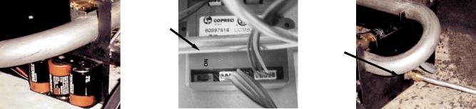
1.Install the 3 C Cell batteries. (See Fig. 1)
2.Locate the switch on the bottom of the control box (see page 13 for control box location) and verify that it is in the “on” position. (See Fig. 2)
3.Remove the black iron pipe cap from your gas supply pipe.
NOTE: Hold the gas supply pipe securely with a wrench to prevent it from rotating loose and unthreading from the inner wall connection.
4.Tighten the 1/2” NPT by the 3/8” flare supply fitting on the 1/2” gas supply line using pipe joint compound.
5.Place the burner assembly in the center of your fireplace.
6.Fasten the aluminum tube from the gas supply to the gas inlet at the side of the heater assembly. (See Fig. 3)
NOTE: The use of a flexible hose to attach the gas supply to the burn assembly may cause the burner to make excessive noise.
Burner |
Switch on |
Gas Line |
requires 3 |
Control |
Hookup |
C batteries. |
Box in |
on right |
Located on |
the “ON” |
side of |
left side of |
position. |
burner |
burner. |
|
|
Fig. 1 |
Fig. 2 |
Fig. 3 |
FINAL CHECKPOINTS BEFORE OPERATION
PILOT OPERATION
1.Before setting the logs in place, turn the gas on and check each joint in the the gas line with soap and water solution for leaks. Bubbles indicate a leak. Repair any leaks and recheck before proceeding.
DANGER: DO NOT USE OPEN FLAME TO TEST FOR LEAKS!
2.We suggest you do a test lighting of the burner assembly before you begin log placement. Be sure to review all safety precautions in the owner's manual before you light your set.
3.Press the on/off button to bleed the pilot system, after a few seconds you will hear a clicking noise as the pilot lights.
4.If the pilot does not light, wait 30 seconds and press the on/off button, you will hear a click, then press again to light the pilot, continue repeating this process until the pilot system lights.
5.It may take several attempts and up to 5 minutes to light the pilot the first time since there will be air in the gas line.
6.Once the pilot flame is lit, wait 15 seconds
7.Then, press the “up” control button.
8.The flame should ignite on the burner bar.
9.Now, press the down control button, the burner should go out and the pilot should remain lit. You are ready for log placement.
5
 Loading...