


SURE HEAT
Installation and Operating Instructions for
NATURAL & L.P. GAS
VENTED GAS LOG SETS
Model: VMR24NG/VMR24LP
Sure Heat Manufacturing
1861 West Oak Parkway
Marietta, GA 30062
Tel: 800-229-5647
Fax: 770-424-3842
WARNING: It is very important to read the instructions in this manual before starting installation.
-Do not attempt to modify or alter the construction of the fireplace or its components. Any modification or alteration of construction may void the warranty of these units.
WARNING: Solid fuel shall not be burned in a fireplace where a decorative gas appliance is installed.
WARNING: If the information in this manual is not followed exactly, a fire or explosion may result causing property damage, personal injury or loss of life.
-Do not store or use gasoline or other flammable vapors and liquids in the vicinity of this or any other appliance.
-WHAT TO DO IF YOU SMELL GAS:
•Do not try to light any appliance.
•Do not touch any electrical switch; do not use any phone in your building.
•Immediately call your gas supplier from a neighbor’s telephone. Follow the gas suppliers instructions.
•If you cannot reach your gas supplier, call the fire department.
-Installation and service must be performed by a qualified installer, service agency or the gas supplier.

-Due to high temperatures, the appliance should be located out of traffic and away from furniture and draperies.
-Do not place clothing or other flammable material on or near the appliance.
-Children and adults should be alerted to the hazards of high surface temperature and should stay away to avoid burns or clothing ignition.
-Young children should be carefully supervised when they are in the same room with the appliance.
-Please retain this manual for future reference.
-The installation must conform with local codes, or in the absence of local codes, with the National Fuel Gas Code ANSI Z223.1/NFPA 54, or the CSA B149.1, Natural Gas and Propane Installation Code
-This appliance must be installed only in a solid fuel fireplace with a working flue and constructed of non-combustible material.
-Installation and repair should be done by a qualified service person.
-The appliance should be inspected before use and at least annually by a qualified service person. More frequent cleaning may be necessary due to excessive dust or carpet lint. It is important that the circulating air passageways be kept clean.
-Keep appliance clear and free from combustible materials, gasoline and other flammable vapors and liquids.
IMPORTANT INFORMATION
FIREPLACE SIZING GUIDE: |
|
|
|
|
|
|
Opening |
Front |
Rear |
Fireplace |
Chimney |
Set Size |
Height |
Width |
Width |
Depth |
Opening |
24” |
18” |
28” |
20” |
15” |
50 sq. in |
The minimum opening that must be provided by the fireplace chimney to vent the unit properly is shown above in the sizing chart.
It is necessary to provide adequate combustion and ventilation air. Air for combustion and ventilation must not be obstructed. Provide adequate clearance around air opening in the combustion chamber and adequate accessibility clearance for servicing and proper operation.
NEVER obstruct the front opening of the fireplace.
WARNING: Any safety guard removed for servicing an appliance must be replaced before operating the appliance
INSTALLATION
Unpacking
Unpack the appliance carefully and inspect for missing parts or damages that may have occurred during shipping. If any part of the appliance is missing or damaged, please notify Sure Heat Manufacturing at (800) 229-5647.
Fireplace Preparation
The fireplace needs to be properly prepared before installing this fireplace unit.
1.Turn off gas supply to the fireplace.
2.Clean chimney and fireplace floor of any combustible material to limit the smell from the system.
Gas Piping and Gas Pressure Requirements
PREPARATION
Check the type of gas that is supplied to your fireplace. Only install the unit that is equipped to operate on the gas that is supplied to your fireplace. All gas piping must be installed to comply with local and national fuel gas codes. Compounds used on threaded joints of gas piping must be resistant to the action of L.P. gas. Before installing the unit, it is necessary to close the main gas valve at the gas meter or L.P. tank. Ensure that there is proper ventilation in the area in which the system is operating.
Page 2
GAS PRESSURE INFORMATION
The minimum inlet gas supply pressure is 5.5 inches water column for natural gas and 11.0 inches water column for propane. The maximum allowable inlet gas supply pressure is 10.5 inches water column for natural gas and 13.0 inches water column for propane. If this appliance is to be supplied with L.P. gas the tank or bottle supplying the gas must have a regulator that reduces gas pressure between 11 and 13 inches water column.
WARNING: |
This appliance must be isolated from the gas supply piping system by closing its individual |
|
|
manual shutoff valve during any pressure testing of the gas supply piping system at test |
|
|
pressures equal to or less than 1/2 PSIG. |
|
|
The appliance and its individual shutoff valve must be disconnected from the gas supply piping |
|
|
system during pressure testing of that system at test pressures in excess of 1/2 PSIG. |
|
|
BTU Information |
|
Set |
Natural Gas |
L.P. Gas |
24" |
60,000 |
60,000 |
Installation to Existing Gas Line in Fireplace
A manual on/off valve should be present within easy reach of the Gas log set. If a manual valve is not present, one must be installed prior to the gas log installation.
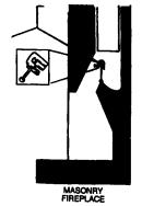
Installation in a Masonry Fireplace
A 1/2" gas supply line must be provided to the fireplace. Most installations require drilling an access hole through the masonry wall. The supply line should be secured and sealed by mortar within the access hole. The supply line should also have an on/off valve in the wall or inside the fireplace.
Damper Clamp Installation
This appliance is only to be installed and burned in a fully vented fireplace with a fully functional damper and chimney that is free of any obstructions. A damper clamp is provided to allow any pilot combustion products to vent. The unit must be operated with the damper in the fully opened position. (See Figure 1).
Figure 1: Damper Stop Clamp
Page 3
Burner System Location
1.The Burner system should be located towards the back and centered in the combustion chamber of the vented fireplace. The burner system should be centered from left to right, with about an inch of space on either side.
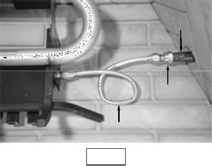
Connecting Gas Supply to Burner Pan and Log Grate Placement
1.Place burner system in proper location.
2.Attach brass 3/8" to 1/2" gas inlet fitting to the 1/2" gas supply stub. (See Figure 2)
3.Carefully bend the flared tubing as needed to make the connection between the burner assembly and the gas inlet fitting.
4.Next attach the flared tubing to the burner assembly first, then to the gas inlet fitting.
-Avoid kinking the flared tubing while bending. If tubing must be cut, use a tube cutter. Flare the cut end of the tube with a flaring tube.
5.Be certain all connections are tight and use pipe compound on all male threads to seal joints.
NOTE: The pipe compound must be resistant to the action of L.P. gas. Test all connections with a soapy water solution with gas supply turned on. If bubbles appear on any connection, retighten and reset. Once it is determine there are no leaks whatsoever, turn off gas supply and move to next assembly step.
Gas Supply
Stub
Gas Inlet
Fitting
Flared
Tubing
Page 4
 Loading...