


 Loading...
XPass 2
INSTALLATION GUIDE 
Version 1.00
English
EN 101.00.XP2-MDPB V1.00A

Contents
Safety instructions............................................................................................ |
3 |
Introduction ...................................................................................................... |
5 |
Components ................................................................................................................................................... |
5 |
Name and function of each part............................................................................................................... |
6 |
Cables and connectors ...................................................................................................................................................... |
7 |
Installation ........................................................................................................ |
8 |
Fixing the bracket and the product.......................................................................................................... |
8 |
Power supply connection............................................................................................................................. |
10 |
Network connection..................................................................................................................................... |
10 |
TCP/IP .................................................................................................................................................................................. |
10 |
TTL input connection ................................................................................................................................. |
11 |
Relay connection.......................................................................................................................................... |
12 |
Fail Safe Lock ...................................................................................................................................................................... |
12 |
Fail Secure Lock .................................................................................................................................................................. |
12 |
Automatic door connection............................................................................................................................................ |
13 |
Connecting as a standalone......................................................................................................................... |
14 |
Connecting to Secure I/O 2 ...................................................................................................................... |
15 |
Wiegand connection .................................................................................................................................... |
16 |
Resetting Network Settings......................................................................................................................... |
17 |
Restoring the Factory Defaults.................................................................................................................... |
17 |
Product specifications.................................................................................. |
18 |
Dimensions................................................................................................................................................... |
19 |
FCC compliance information ...................................................................... |
20 |
Appendices..................................................................................................... |
21 |
Disclaimers ................................................................................................................................................... |
21 |
Copyright notice.......................................................................................................................................... |
21 |
Open Source License .................................................................................................................................... |
21 |
GNU General Public License.............................................................................................................................................. |
21 |
GNU Lesser General Public License .................................................................................................................................. |
27 |
OpenSSL License ................................................................................................................................................................ |
29 |
Original SSLeay License..................................................................................................................................................... |
29 |

Safety instructions
Safety instructions
Observe the following instructions to use the product safely and prevent any risk of injury or property damage.
 Warning
Noncompliance of instructions could lead to serious injury or death.
Installation
Do not install the product in a place with direct sunlight, moisture, dust, or soot.
•A fire or electric shock may occur.
Do not install the product in a place with heat from an electric heater.
•A fire or electric shock may occur due to overheating.
Install the product in a dry place.
•Otherwise, a product damage or electric shock may occur due to moisture.
Install the product in a place with no electromagnetic interference.
• Otherwise, a product damage or electric shock may occur.
The user should not install or repair the product independently.
•A fire, electric shock, or personal injury may occur.
•If the product has been damaged due to independent installation or repair of the product by the user, free A/S service will not be provided.
Operation
Do not allow liquids such as water, beverages, or chemicals get into the product.
•A fire, electric shock, or product damage may occur.
 Caution
Noncompliance of instructions could lead to minor injury or product damage.
Installation
Do not install the power supply cable in a place where people pass by.
•Product damage or physical injury may occur.
Do not install the product near a highly magnetic object such as a magnet, TV, (especially CRT) monitor, or speaker.
•A product failure may occur.
If installing the product outside where the product is completely exposed, it is recommended to install the product together with the enclosure.
Keep the minimum separation distances between the devices when install multiple devices.
•Otherwise, RF performance is affect to the other device, the devices may not operate normally.
3

Safety instructions
Operation
Do not drop the product or apply an impact to the product.
•A product failure may occur.
When cleaning the product, wipe the product with a soft and dry cloth and no water, benzene or alcohol.
•Otherwise, a product failure may occur.
4

Introduction
Introduction
Components
XPass 2 |
Wall Bracket |
Drilling Template |
Diode
Wall Fixing Screw x 2 |
Bracket Fixing Screw |
Ferrite Core |
|
120 Ω resistor |
|
(Star Shaped) |
|
|
|
|
|
|
|
|
|
|
|
|
|
Shrink Tube |
PVC Anchor x 2 |
Quick Guide |
Open Source Software Guide |
NOTE
•Components may vary according to the installation environment.
5

Introduction
Name and function of each part
LED lamp
RF card authentication unit
Reset button
Cable
|
Name |
|
|
Description |
|
|
|
|
|
|
LED lamp |
|
Indicates the operational status of the device with the color of the LED lamp. |
|
|
|
|
|
|
|
RF card authentication unit |
|
Reads RF cards for entering and exiting. |
|
|
|
|
|
|
|
Reset button |
|
Initialize the device. |
|
|
|
|
|
|
|
|
|
• |
Power cable |
|
|
|
• |
RS485 cable |
|
Cable |
|
• |
Ethernet cable |
|
|
• |
Wiegand input/output cable |
|
|
|
|
||
|
|
|
• |
TTL input cable |
|
|
|
• |
Relay cable |
6
Introduction
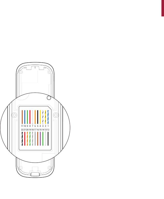
Cables and connectors
|
Pin |
|
|
|
Name |
|
|
|
Color |
|
|
|
|
|
|
|
|
|
|
|
|
|
|
|
|
|
|
|
|
|
|
|
1 |
|
|
|
485 TRXP |
|
|
Blue (White stripe) |
|||
|
|
|
|
|
||||||
|
|
|
|
|
|
|
|
|||
2 |
|
|
|
485 TRXN |
|
|
Yellow (Black stripe) |
|||
|
|
|
|
|
|
|
|
|||
3 |
|
|
|
485 GND |
|
|
White (Black stripe) |
|||
|
|
|
|
|
|
|
|
|||
4 |
|
|
|
ENET RXN |
|
|
Yellow |
|||
|
|
|
|
|
|
|
|
|||
5 |
|
|
|
ENET RXP |
|
|
Black |
|||
|
|
|
|
|
|
|
|
|||
6 |
|
|
|
ENET TXN |
|
|
Orange |
|||
|
|
|
|
|
|
|
|
|||
7 |
|
|
|
ENET TXP |
|
|
White |
|||
|
|
|
|
|
|
|
|
|||
8 |
|
|
|
ENET VB1 |
|
|
Red |
|||
|
|
|
|
|
|
|
|
|||
9 |
|
|
|
ENET VB1 |
|
|
Green |
|||
|
|
|
|
|
|
|
|
|||
10 |
|
|
|
ENET VB2 |
|
|
Blue |
|||
|
|
|
|
|
|
|
|
|||
11 |
|
|
|
ENET VB2 |
|
|
Brown |
|||
|
|
|
|
|
|
|
|
|||
12 |
|
|
|
WG GND |
|
|
Black |
|||
|
|
|
|
|
|
|
|
|||
13 |
|
|
|
WG D1 |
|
|
White |
|||
|
|
|
|
|
|
|
|
|||
14 |
|
|
|
WG D0 |
|
|
Green |
|||
|
|
|
|
|
|
|
|
|||
15 |
|
|
|
TTL IN0 |
|
|
Purple |
|||
|
|
|
|
|
|
|
|
|||
16 |
|
|
|
TTL IN1 |
|
|
Brown |
|||
|
|
|
|
|
|
|
|
|||
17 |
|
|
|
TTL GND |
|
|
Gray |
|||
|
|
|
|
|
|
|
|
|||
18 |
|
|
|
RLY NO |
|
|
Gray (White stripe) |
|||
|
|
|
|
|
|
|
|
|||
19 |
|
|
|
RLY COM |
|
|
Green (White stripe) |
|||
|
|
|
|
|
|
|
|
|||
20 |
|
|
|
RLY NC |
|
|
Orange (White stripe) |
|||
|
|
|
|
|
|
|
|
|||
21 |
|
|
|
PWR +VDC |
|
|
Red |
|||
|
|
|
|
|
|
|
|
|||
22 |
|
|
|
PWR GND |
|
|
Black (White stripe) |
|||
|
|
|
|
|
|
|
|
|
|
|
7
Installation
Installation
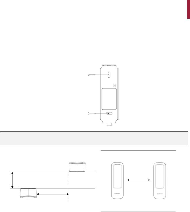
Fixing the bracket and the product
1 Determine the correct position to install the bracket using the provided drilling template. Fix the bracket firmly using fixing screws through the bracket to the position where XPass 2 will be installed.
NOTE
•If installing XPass 2 on a concrete wall, drill holes, insert PVC anchors, and fix them with fixing screws.
•To avoid RF interference, a minimum separation distance must be maintained.
Wall
Wall |
400 mm |
|
Wall thickness |
||
|
||
Distance |
|
|
Wall thickness |
|
Distance |
|
|
||
|
100 mm |
|
360 mm |
|
|
||
|
120 mm |
|
360 mm |
|
150 mm |
|
300 mm |
8

Installation
2 Install XPass 2 onto the fixed bracket.
Wall
3 Assemble XPass 2 with the bracket by rotating the product fixing screw.
Wall
NOTE
•When assembling the product with the bracket, you can use the included bracket fixing screw(Star Shaped) instead of the product fixing screw for enhanced security.
9
Installation
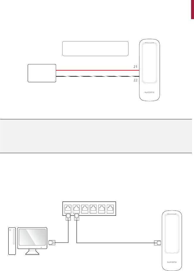
Power supply connection
21 |
- PWR +VDC |
Red |
22 |
- PWR GND |
Black (White stripe) |
DC power
XPass 2
NOTE
•Use a power supply adaptor of DC 12 V (± 10%) with a minimum of 1,000 mA or DC 24V (± 10%) with a minimum of 500 mA which has obtained the approval of IEC/EN 60950-1. If you wish to connect and use another device to the power supply adaptor, you should use an adaptor with a current capacity which is the same or larger than the total power consumption required for the terminal and another device.
•Use a separate power supply for Secure I/O 2, the electric lock, and the product respectively. If connecting and using the power supply to these devices together, the devices may malfunction.
Network connection
TCP/IP
LAN connection (connecting to a hub)
You can connect the product to a hub using a general type CAT-5e cable.
Hub
PC
XPass 2
10
Loading...