

Page 1

English
Version 1.00
OM-120
INSTALLATION GUIDE
www.supremainc.com
EN 101.00.OM120 V1.00A
Page 2

Contents
Safety Instructions .......................................................................................... 3
Components ...................................................................................................... 4
Front Side ......................................................................................................... 5
LED Status ...................................................................................................................................................... 6
Installation Example ......................................................................................... 7
Dimensions ........................................................................................................ 8
Installation ........................................................................................................ 9
Connections ................................................................................................... 10
Power ............................................................................................................................................................ 10
RS-485 ........................................................................................................................................................... 10
Relay ............................................................................................................................................................. 11
AUX ............................................................................................................................................................... 12
Product Specifications ................................................................................. 13
FCC Compliance Information ....................................................................... 14
Appendix ........................................................................................................ 15
Disclaimers ................................................................................................................................................... 15
Copyright Notice ......................................................................................................................................... 15
Page 3

Safety Instructions
3
Safety Instructions
Please read the following instructions carefully before using the product. This information is important for ensuring the safety of the user
and for preventing damage to the user's property.
Warning
Violation of the instructions may cause serious injury or death.
Installation Instructions
Do not install the product in direct sunlight or in a location that is damp or dusty.
• This can cause a fire or electric shock.
Do not install the product near any heat source such as electric heaters.
• This can cause a fire from overheat or electric shock.
Install the product in a dry place.
• Moisture can cause product damage or electric shock.
Install the product in a place where there is no electromagnetic interference.
• This can cause product damage or electric shock.
Have qualified service professionals install or repair the product.
• Otherwise, it can cause a fire, electric shock, or injury.
• If the product is damaged due to a user's unauthorized installation or dismantling of the product, a service fee will be charged for repair.
Caution
Ignoring these instructions may result in minor injuries or damage to the product.
Installation Instructions
Protect the power cord from being walked on or pinched.
• This can cause product damage or injury.
Keep the product away from strong magnetic objects such as magnets, TVs, monitors (especially CRT monitors), or speakers.
• This can cause a failure.
Operating Instructions
Do not drop the product or subject it to shock or impact during use.
• This can cause a failure.
Do not press the buttons on the product with excessive force or with a sharp tool.
• This can cause a failure.
Clean the product with a soft, dry cloth. Do not use alcohol, benzene, or water.
• This can cause a product failure.
Page 4
Components
4
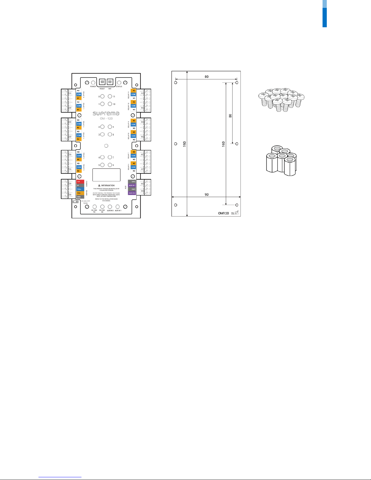
Components
OM-120
Spacer
(6)
Mounting screws
(12)
Drilling Template
Page 5
Front Side
5
Front Side
• Press INIT button to reset OM-120 interworking with a device and then connect to another device.
Note
Power status LED
Operation
status LED
P
ower
RS-
485
RESET button
INIT button
Relay 2
Relay 0
Relay 1
Relay 3
Relay 4
Relay 5
Relay
10
Relay
11
Relay
status LED
(0, 1, 11, 10)
Relay
9
Relay
8
Relay 7 Relay
6
AUX
1
AUX
0
T
ermination
S
witch
Communication status LED
(RS-485, AUX)
Relay status
LED
(2, 3, 9, 8)
Relay status
LED
(4, 5, 7, 6)
Page 6

Front Side
6
LED Status
LED Status
POWER
Solid red: Power is on.
STAT US
Solid green: Connected with the secure session.
Solid blue: Disconnected from the master device.
Solid pink: Upgrading the firmware.
Solid yellow: RS-485 communication error due to different encryption key or OSDP packet los s.
Solid sky blue: Connected without the secure session.
RELAY (0 ~ 11)
Solid red: Relay operation.
RS-485 TX
Pulsing green: Transmitting RS-485 data
RS-485 RX
Pulsing orange : Receiving RS-485 data
AUX IN (0, 1)
Pulsing orange : Receiving AUX signal
Page 7

Installation Example
7
Installation Example
OM-120 is an expansion module for floor access control. Combined with Suprema device and BioStar 2, a single module can control 12
floors. When the OM-120 is connected as daisy chain via RS-485, you can control up to 192 floors per elevator.
Page 8

Dimensions
8
Dimensions
(Unit
: mm)
Page 9

Installation
9
Installation
OM-120 can be mounted in the cabinet or elevator control panel.
1 With the mounting screws, fix the spacer firmly onto the surface where OM-120 is to be installed.
2 With the mounting screws, mount the OM-120 firmly onto the spacer.
Page 10

Connections
10
Connections
Power
• Do not share the power with the access controller.
RS-485
• RS-485 should be AWG24, twisted pair, and maximum length is 1.2 km.
• Connect a termination resistor (120Ω) to both ends of a RS-485 daisy chain connection. It should be installed at both ends of the daisy
chain. If it is installed in the middle of the chain, the performance in communicating will deteriorate because it reduces the signal level.
• Up to 31 modules can be connected to the master device.
RS
-485 TRX-
GND
Access Controller
Termination
(120Ω)
OM-120
Termination
RS
-485 TRX+
DC
power
12V
GND
Page 11

Connections
11
Relay
• Relay connection may vary depending on the elevator. Please consult your elevator installer for details.
• Each relay has to be connected to the corresponding floor.
• Use the figure below as an example.
B3
Elevator Control Panel
B2
B1
1
Elevator Floor Button
Page 12

Connections
12
AUX
• The dry contact output or tamper can be connected..
Tam per
Page 13

Product Specifications
13
Product Specifications
Category Feature Specification
General
CPU
Cortex M3 72MHz
Memory
Flash 128KB, SRAM 20KB
LED
Multi-color
• POWER 1 ea
• RELAY 12 ea
• RS-485 2 ea
• AUX IN 2 ea
• STATUS 1 ea
Operating temperature
-20°C ~ 60°C
Storage temperature
-40°C ~ 70°C
Operating humidity
0% ~ 95%, non-condensing
Storage humidity
0% ~ 95%, non-condensing
Dimension (W x H x D)
90 mm x 190 mm x 21 mm
Weight
300 g
Certificates
CE, FCC, KC, RoHS, REACH, WEEE
Interface
RS-485
1ch
AUX input
2ch Dry Contact Input
Relay
12 relays
Electrical
Power
Voltage: 12VDC
Current: Max. 1 A
Switch input VIH
Max.: 5 V (Dry Contact)
Relay
Voltage: Max. 30 VDC
Current: Max. 5 A
Page 14

FCC Compliance Information
14
FCC Compliance Information
THIS DEVICE COMPLIES WITH PART 15 OF THE FCC RULES.
Operation is subject to the following two conditions:
(1) This device may not cause harmful interference, and
(2) This device must accept any interference received, including interference that may cause undesired operation.
NOTE: This equipment has been tested and found to comply with the limits for a Class A digital device, pursuant to Part 15 of the FCC Rules.
These limits are designed to provide reasonable protection against harmful interference when the equipment is operated in a commercial
environment. This equipment generates, uses, and can radiate radio frequency energy and, if not installed and used in accordance with the
instruction manual, may cause harmful interference to radio communications. Operation of this equipment in a residential area is likely to
cause harmful interference in which case the user will be required to correct the interference at his own expense.
Modifications not expressly approved by the manufacturer could void the user's authority to operate the equipment under FCC rules.
Page 15

Appendix
15
Appendix
Disclaimers
• This document provides the information pertaining to Suprema's products.
• The right of use is granted only to the products that are covered by the sales agreement and conditions guaranteed by Suprema. Any
license of intellectual property that is not dealt within this document is not granted.
• Suprema does not provide any warranty or liability of fitness or merchantability for a particular purpose and of infringement of patents,
copyrights, or other intellectual properties, regarding the sales or use of Suprema's products.
• Do not use Suprema's products in either circumstances where people could be hurt or die as a consequence of malfunctions of the
products or circumstances related to medical treatments, the rescue of lives, or life supports. If a user suffers an accident in one of the
circumstances mentioned above, employees, subsidiaries, branches, partners, and distributors of Suprema are exempt from liability
even when it is claimed that there is a significant fault in the design or production process, and also they are not liable for any direct or
indirect cost or expenditure including legal costs.
• Suprema can change the standard and specification of its products anytime without notice in order to improve the stability, functions,
or design of the products. Designers should keep in mind that the functions or explanations denoted as "to be implemented" or "not
defined" can be changed anytime. Suprema will implement or define such items in the shortest possible time, and will not accept any
liability for problems incurred including compatibility issues.
• Contact Suprema, sales representatives of Suprema, or local distributors in order to get the latest specifications before ordering
products.
Copyright Notice
Suprema has the copyright of this document. The rights of other product names, brands, and trademarks belong to individuals or
organizations who own them.
Page 16

www.supremainc.com
www.supremainc.com
 Loading...