

Page 1
SERVICE MANUAL
8T83 CHASSIS
15.1INCH LCD TV
MANUAL
Design and specifications are subject to change without prior notice.
( ONLY REFERRENCE)
ENGINEER BY: CHECKED BY: PPROVED BY:
_____
_____
_____
Page 2

Contents
Note
----------------------------------------------------------------Technical specification-------------------------------------------Chassis Block Diagram-------------------------------------------IC Block Diagram --------------------------------------------------Transistor mark ---------------------------------------------------PCB Top/Bottom layer --------------------------------------------Service Adjustments ----------------------------------------------Control Location ---------------------------------------------------Input and Output Terminals--------------------------------------Operation Instructions
--------------------------------------------Cabinet parts List -------------------------------------------------Circuit Diagram-----------------------------------------------------
2
3-4
5
6-8
9
10-14
15-16
17
18
19-26
27
28
-2-
Page 3
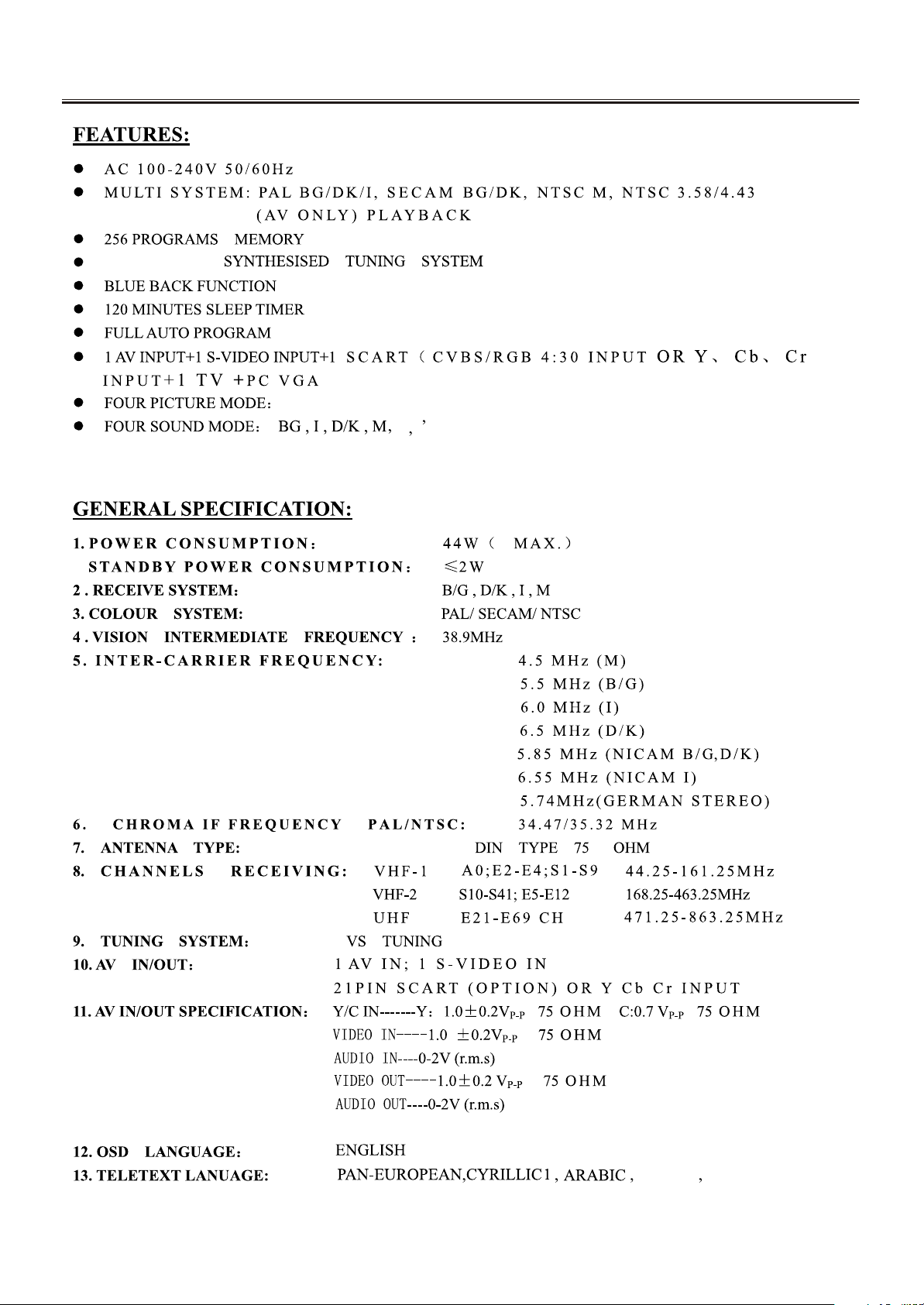
TECHNICAL SPECIFICATION
Frequency
CUSTOM , SOFT , STANDARD ,RICH
L L
-3-
LATIN GREEK
Page 4

TECHNICAL SPECIFICATION
-4-
Page 5
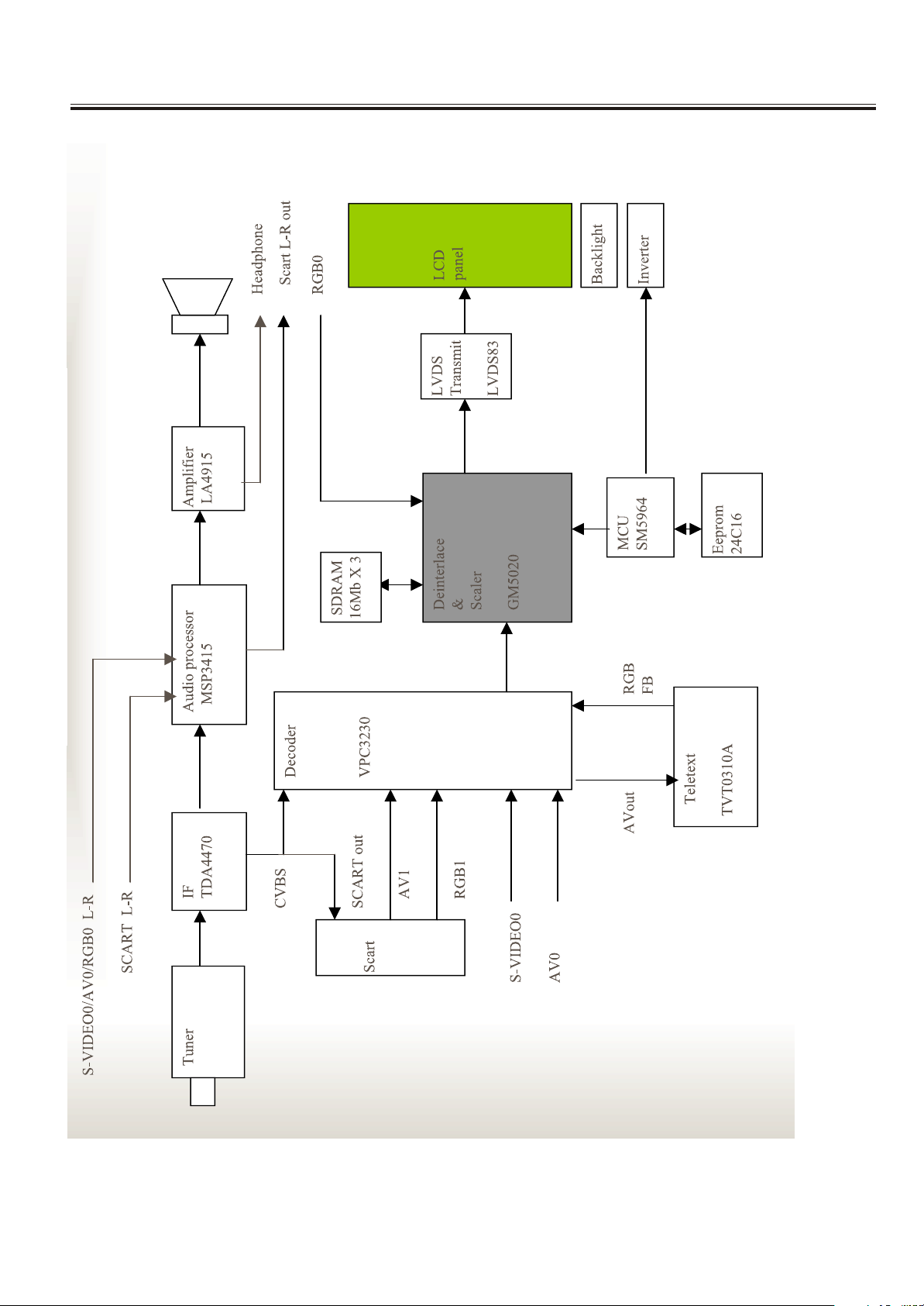
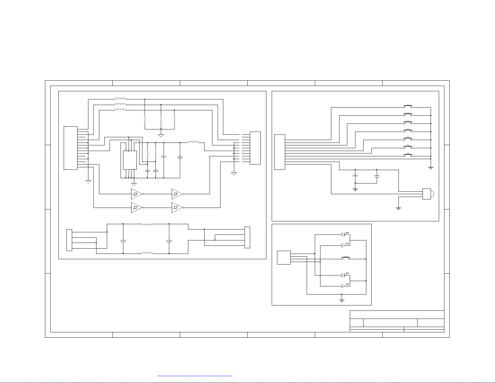
Chassis Block Diagram
-5-
Page 6
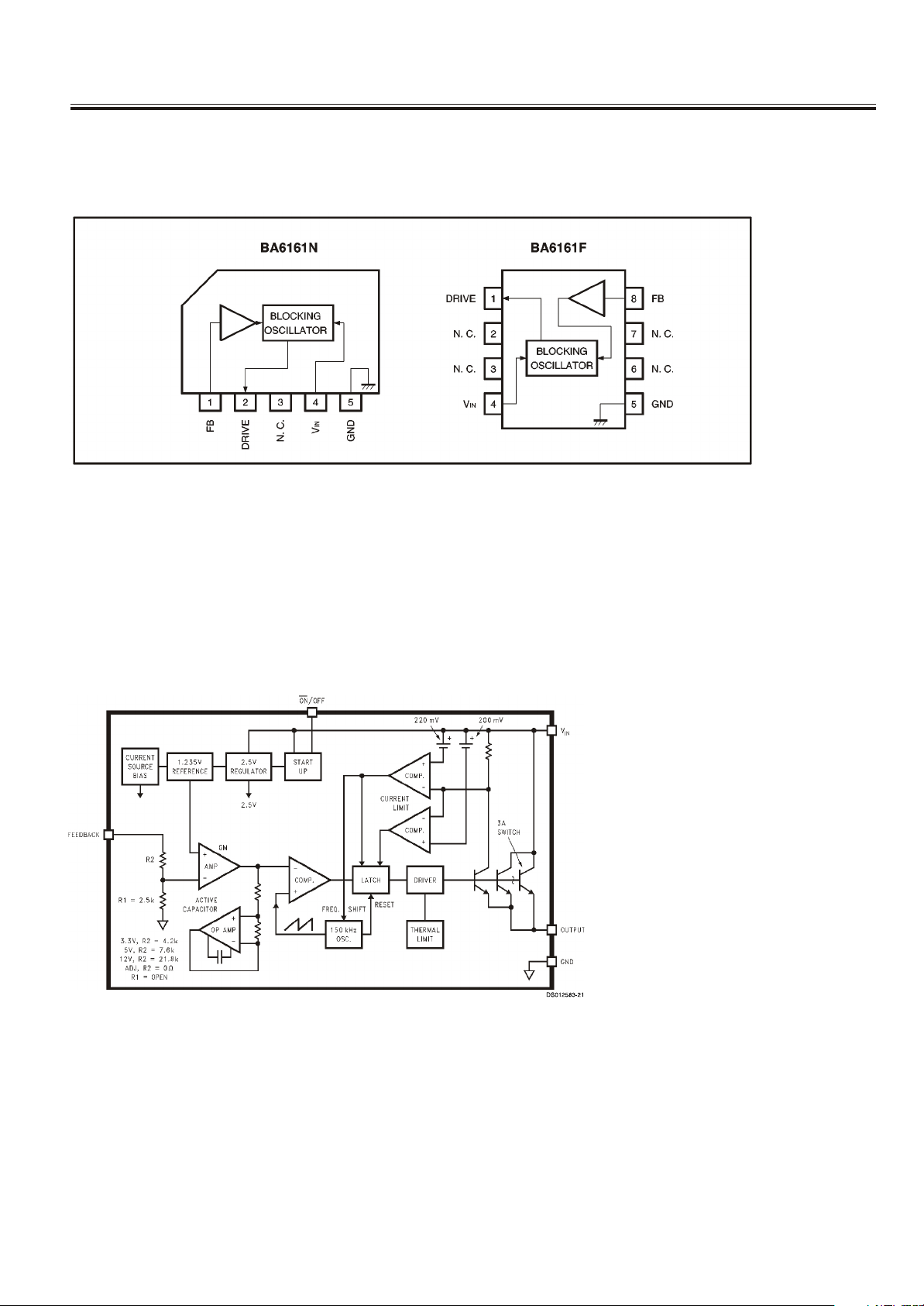
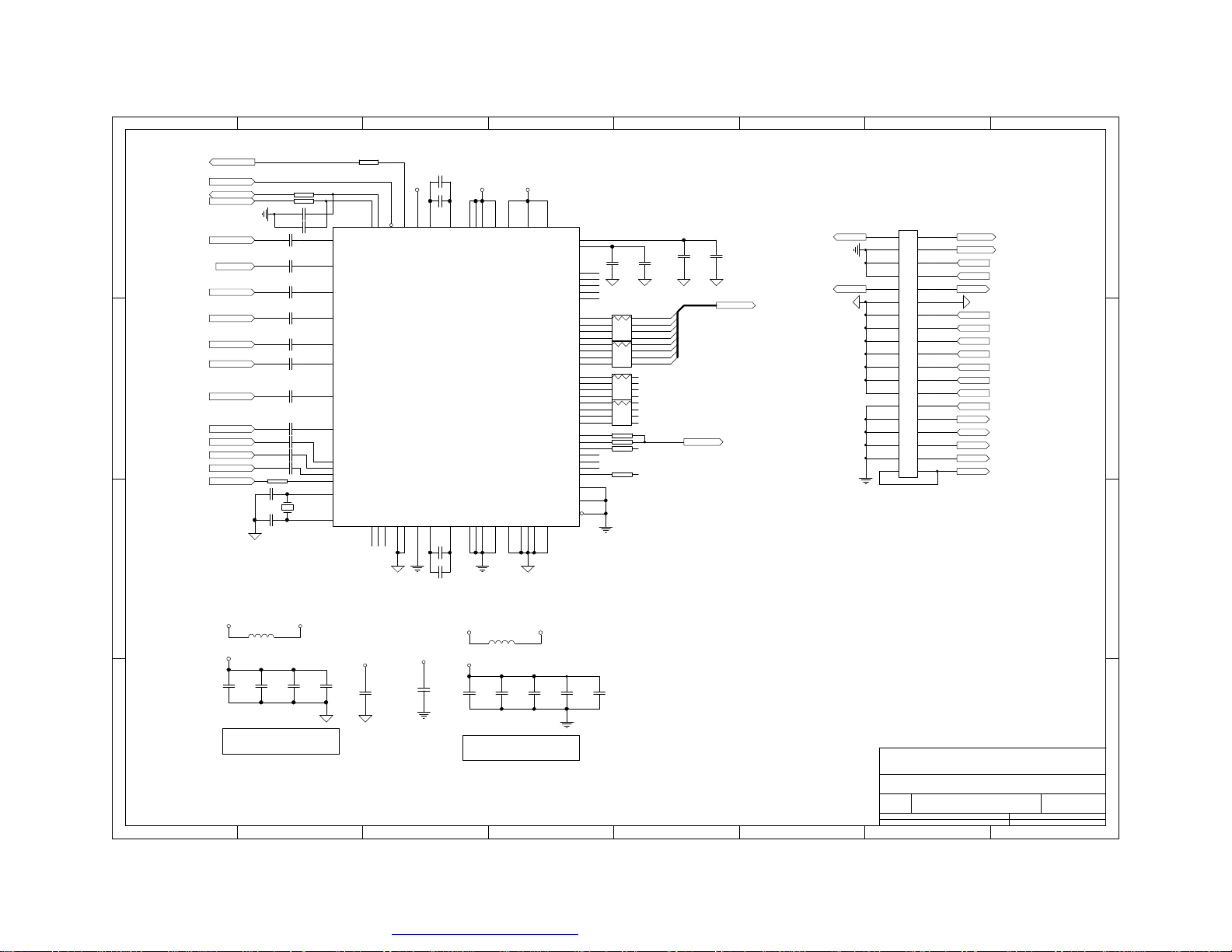
IC Block Diagram
IC 900 ( SWITCHING REGULATOR FOR ELECTRONIC TUNING) BA6161A
IC 905(3A STEP-DOWN VOLTAGE REGULATOR) LM2596S
-6-
Page 7
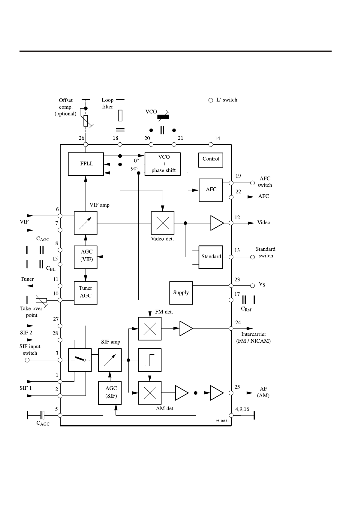
IC Block Diagram
IC2 (MULTI STANDARD VIDEO-IF)TDA4470
IC602(POWER ) STR-G6653
-7-
Page 8
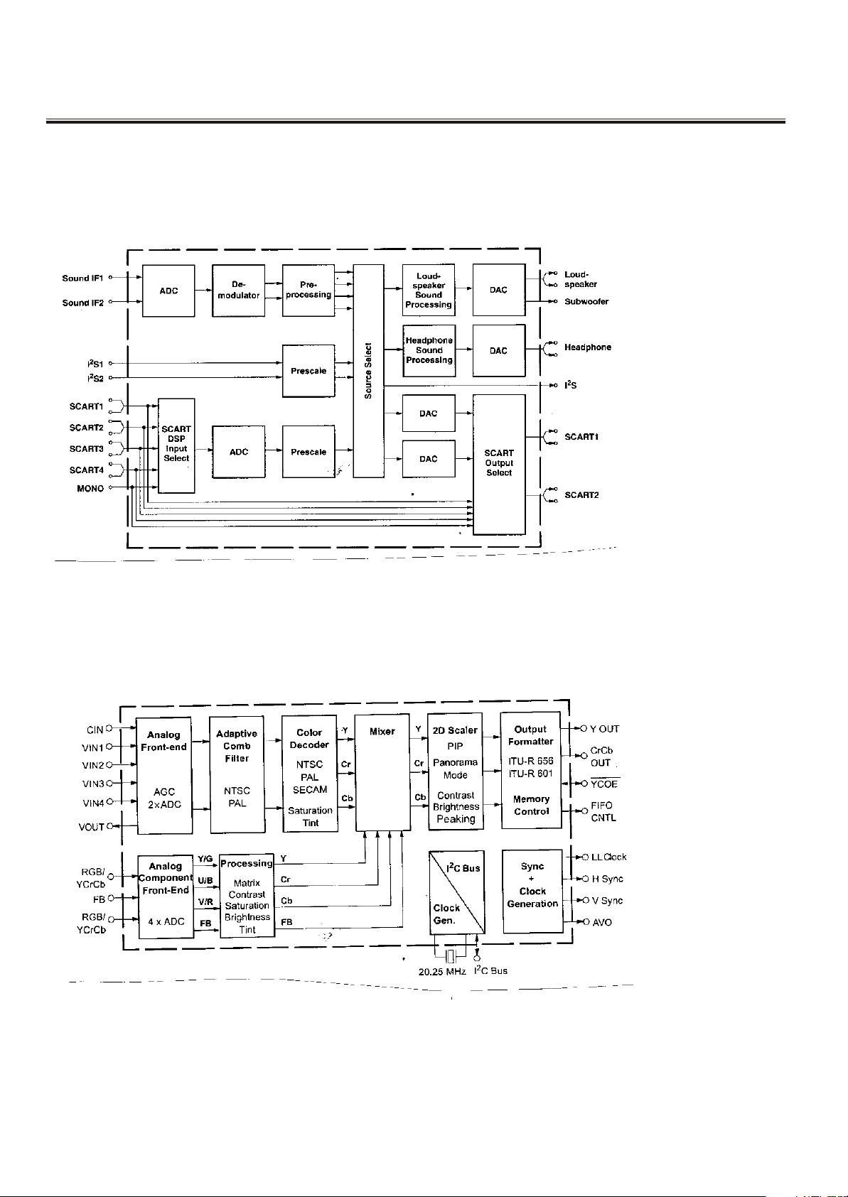
IC Block Diagram
IC 300 (Multi standard Sound Processor Familyt) MSP3415G
Ic700 (Filter Video Processor ) VPC3230D-C5
-8-
Page 9
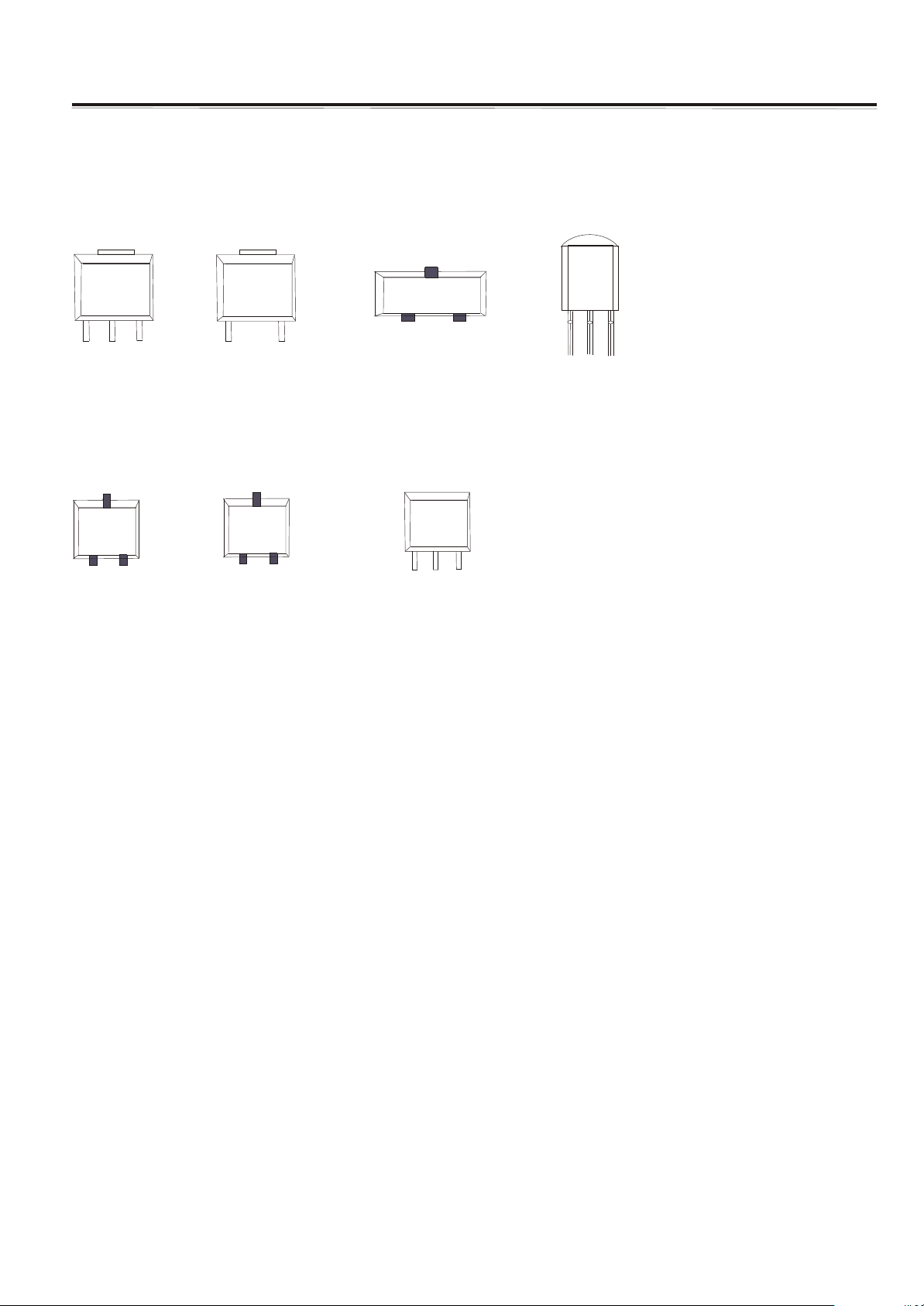
Transistor Mark
AMS1117
GND
OUTPUT
C
S3904
B E
INPUT
MC78
INPUT
S3906
B E
GND
M0
C
5C
OUTPUT
VCC
DT
IMP809
LM
7
8
L
08
GND RESET
GND
OUTPUT
INPUT
LM1086
OUTPUT
INPUT
GND
-9-
Page 10
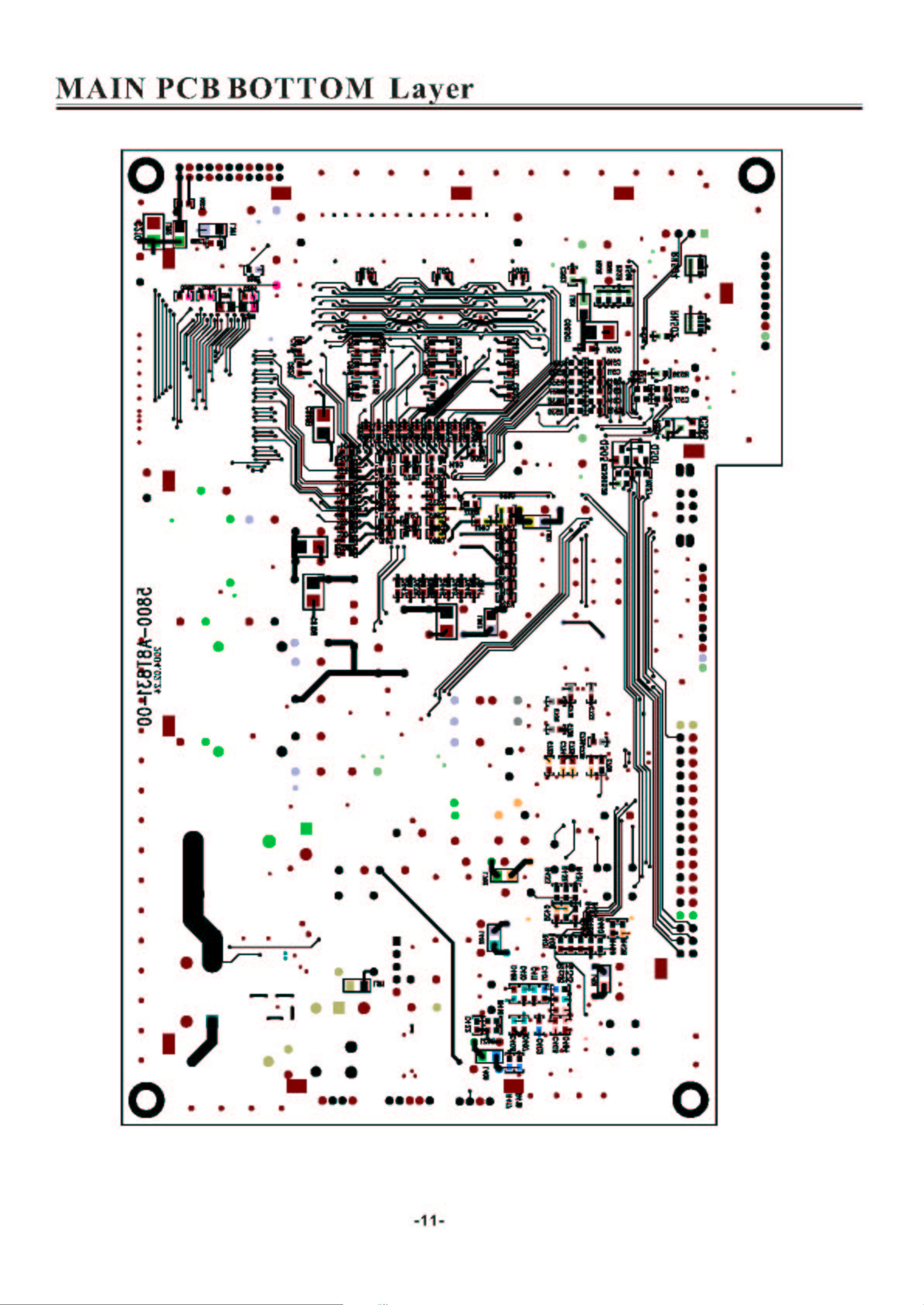
Page 11
Page 12
AV IN/OUT PC IN PCB Top Layer
-12-
Page 13
AV IN/OUT PC IN PCB BOTTOM Layer
-13-
Page 14
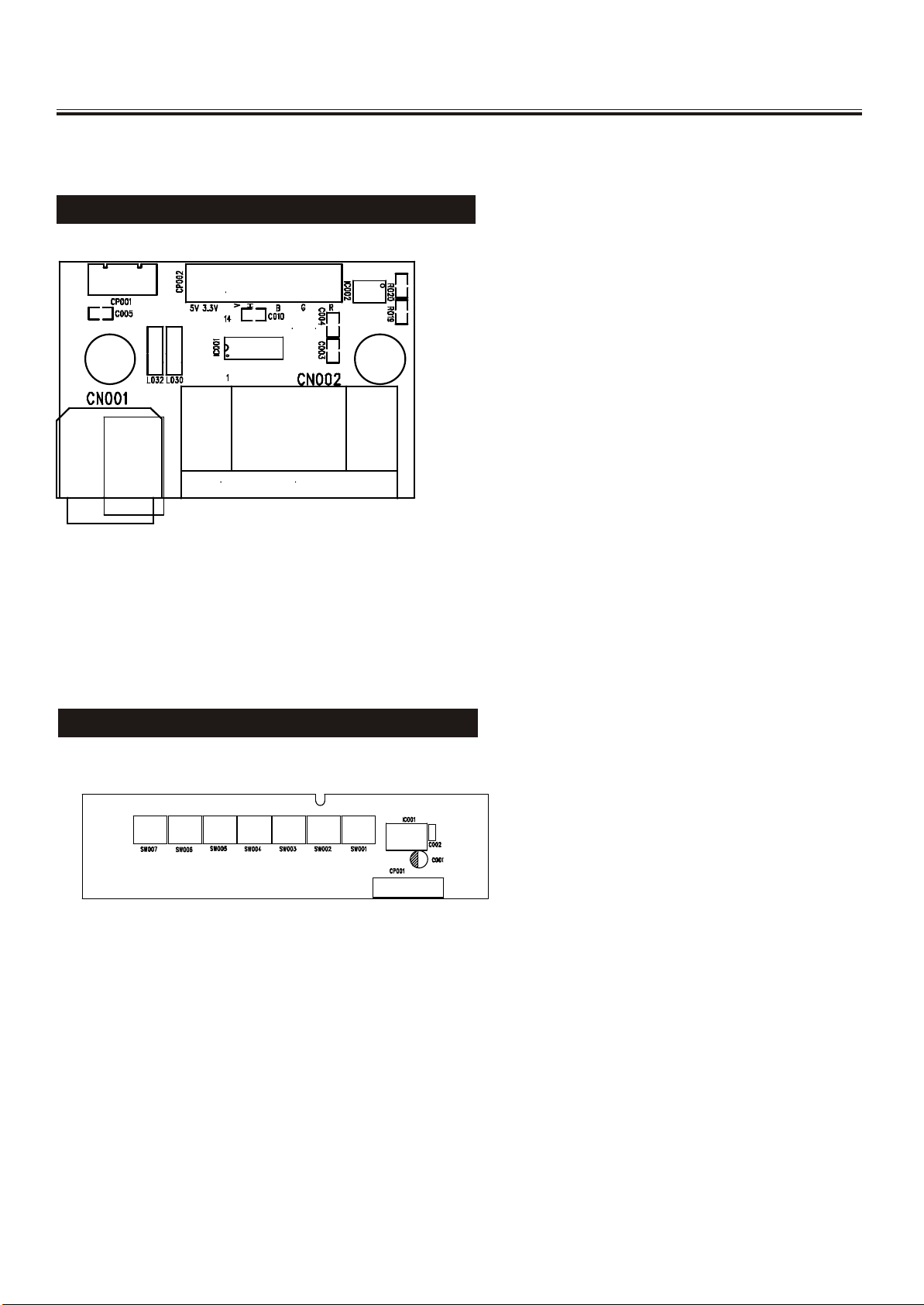
VGA&CONTROL PCB Top Layer
VGA PCB TOP LAYER
CONTROL PCB TOP LAYER
-14-
Page 15
Service Adjustments
-15-
Page 16
Service Adjustments
-16-
Page 17
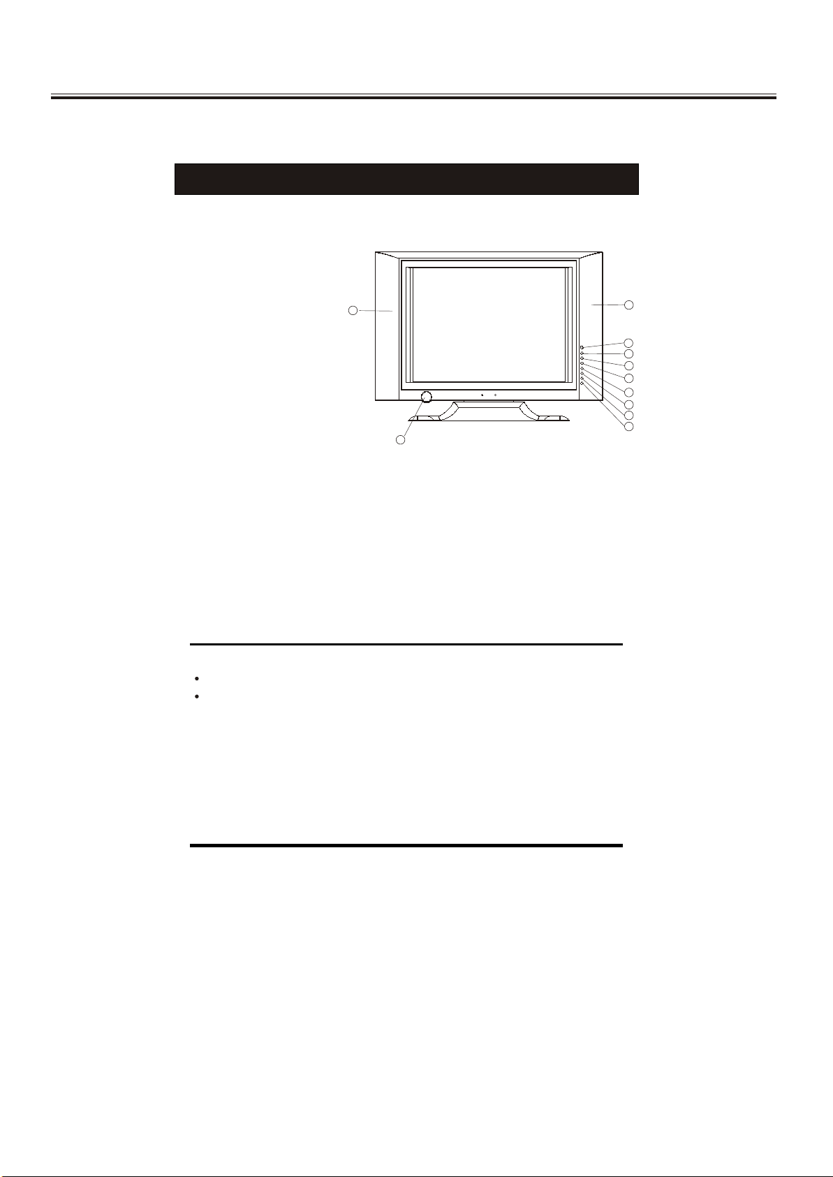
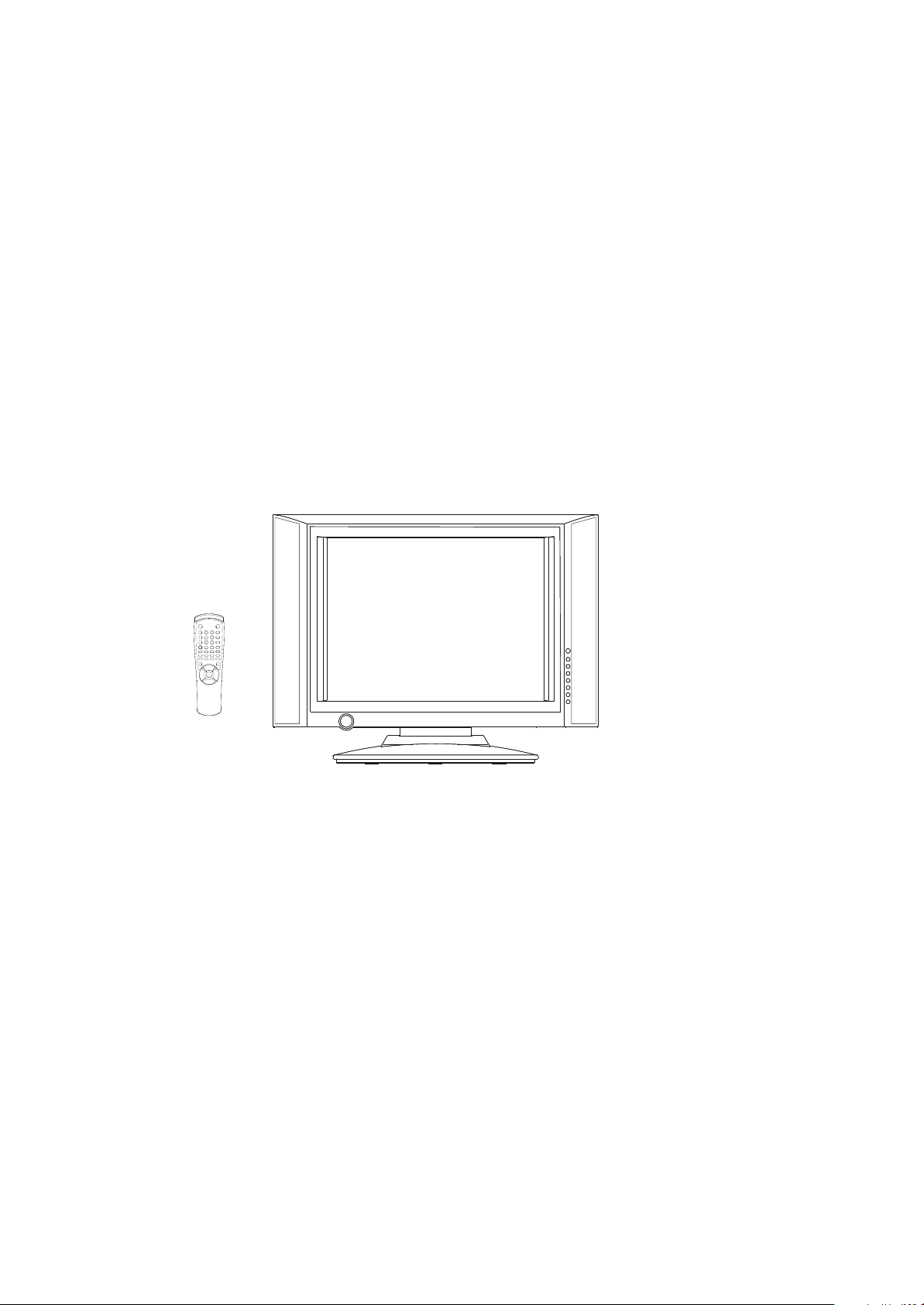
Control Location
FUNCTIONAL PARTS
Front View of TV Set
1. Remote Sensor
2. AV Button
3. OK Button
4. Main Menu Button
5. PROG.+Button
6. PROG.- Button
7. VOL.+Button
8. VOL.- Button
9. Power Indicator/Stand by Button
10. Speakers
1010
99
1010
11
22
33
44
55
66
77
88
To turn the TV power ON
Put the TV set on the correct place, then connect the DC plug of the AC-DC adaptor
to the DC 12V socket at the back or the TV set. Connect the adaptor main cord to
the wall outlet, then the power indicator will turn red, the TV set at Standby Mode.
After you press the Standby Button the power indicator will change to green. It need
a few second before the picture appear.
To turn the TV power OFF
Press the Standby Button to make the TV set in Standby Mode., then disconnect
the power plug from the wall outlet.
NOTE
If the TV set does not receive any signal for 5 minutes, it will enter standby mode.
If you are not going to use this TV set for a long time, switch off the set using
the power switch on the TV set and disconnect the power plug from the wall outlet.
-17-
Page 18
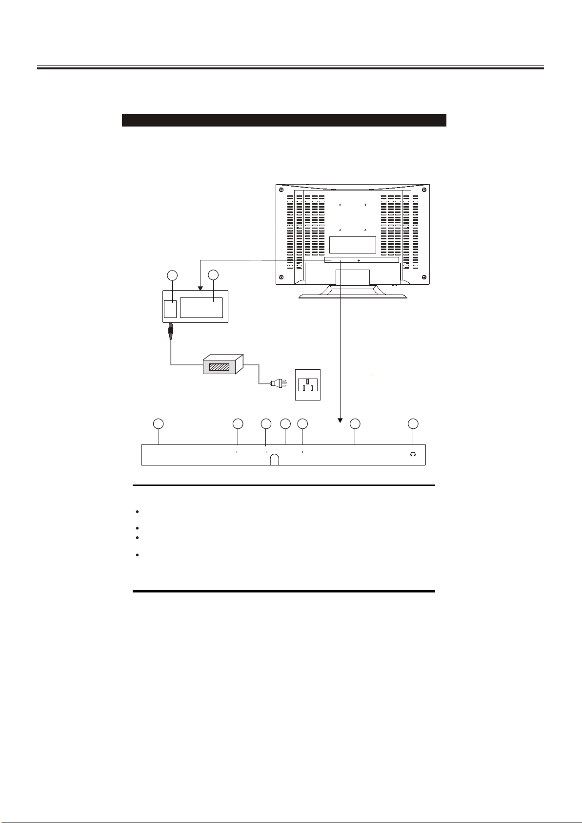
Operation Instructions
Rear View of TV Set
1. DC 12V In
2. VGA In
AV Audio Right In
3.
4. AV Audio Left In
5. AV Video In
6. S-VIDEO IN
7. Antenna Input Socket(75Ohm)
8. SCART
9. PHONE
11
DC12VDC12V PC INPUTPC INPUT
22
Adaptor
55
66
ANT INANT IN
NOTE
S.VIDEO and AV IN 1 (VIDEO) inputs cannot be used at the same time.
Precautions when connecting to other equipment
When using external equipment with this TV set, please read the instruction
manual of the external equipment.
Switch off all power supplies to the equipment and TV set before connection.
Always ensure that the input and output terminals are correctly connected.
33
4477
VIDEOVIDEOS-VIDEO S-VIDEO PHONE PHONE
LLRR
88
SCARTSCART
99
-18-
Page 19
Operation Instructions
Remote Control Unit
P.M .
SYS
6
9
Q.
VIEW
XX
I/II
HOLD
CH
MENUMENU VOL.+VOL.-
CH
6 6
55
1
2 3
4
5
7
8
- /- -
0
MIX INDEX LANGUAGE
REVEAL SIZE SUB. PAGE
AV OK
1
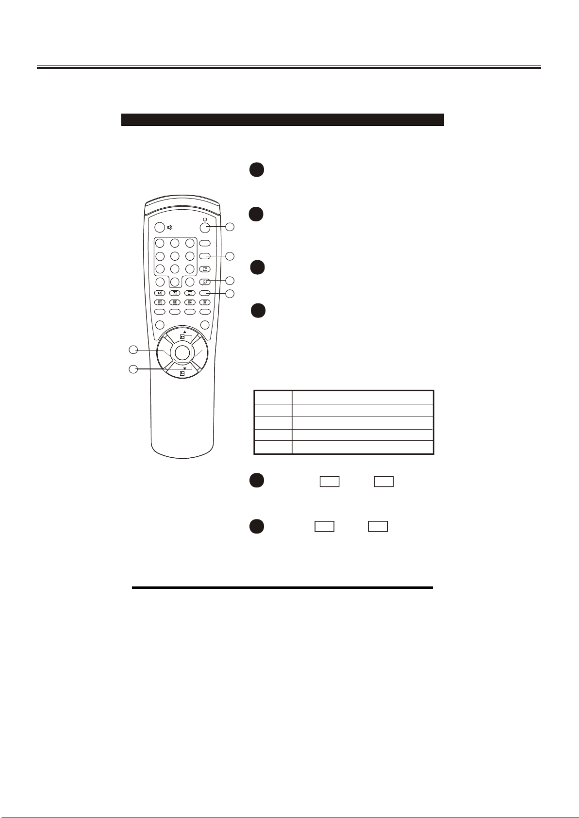
POWER ON / STANDBY button
Press this button to switch on the TV when
at standby mode.
2
SLEEP button
11
Press this button to set the sleep timer.
When the preset length of time has passed,
the TV set enters standby mode.
33
3
SOUND SYSTEM button
22
44
Press this button to select the correct
sound system.
4
STEREO/BILINGUAL SOUND button (option)
When stereo program is received, press
this button to select STEREO or MONO.
When bilingual program is received, press
this button to select DUAL-1, DUAL-2 or
MONO.
The screen will display NICAM or A2 when
such broadcast is received.
Mode Description
STEREO
MONO
DUAL-1
DUAL-2
Stereo mode.
Mono mode.
Multi-sound channel for language 1.
Multi-sound channel for language 2.
5
CHANNEL UP / DOWN
CH
+
-
CH
buttons
Press these buttons to select channels in
ascending or descending order.
VOL
6
VOLUME UP / DOWN buttons
+
VOL
-
Press these buttons to adjust the volume level
up or down.
-19-
Page 20
Operation Instructions
Remote Control Unit
77
1
2 3
4
1111
1010
5
7
8
- /- -
0
MIX INDEX LANGUAGE
REVEAL SIZE SUB. PAGE
AV OK
P.M .
SYS
6
9
Q.
VIEW
XX
I/II
HOLD
CH
MENUMENU VOL.+VOL.-
CH
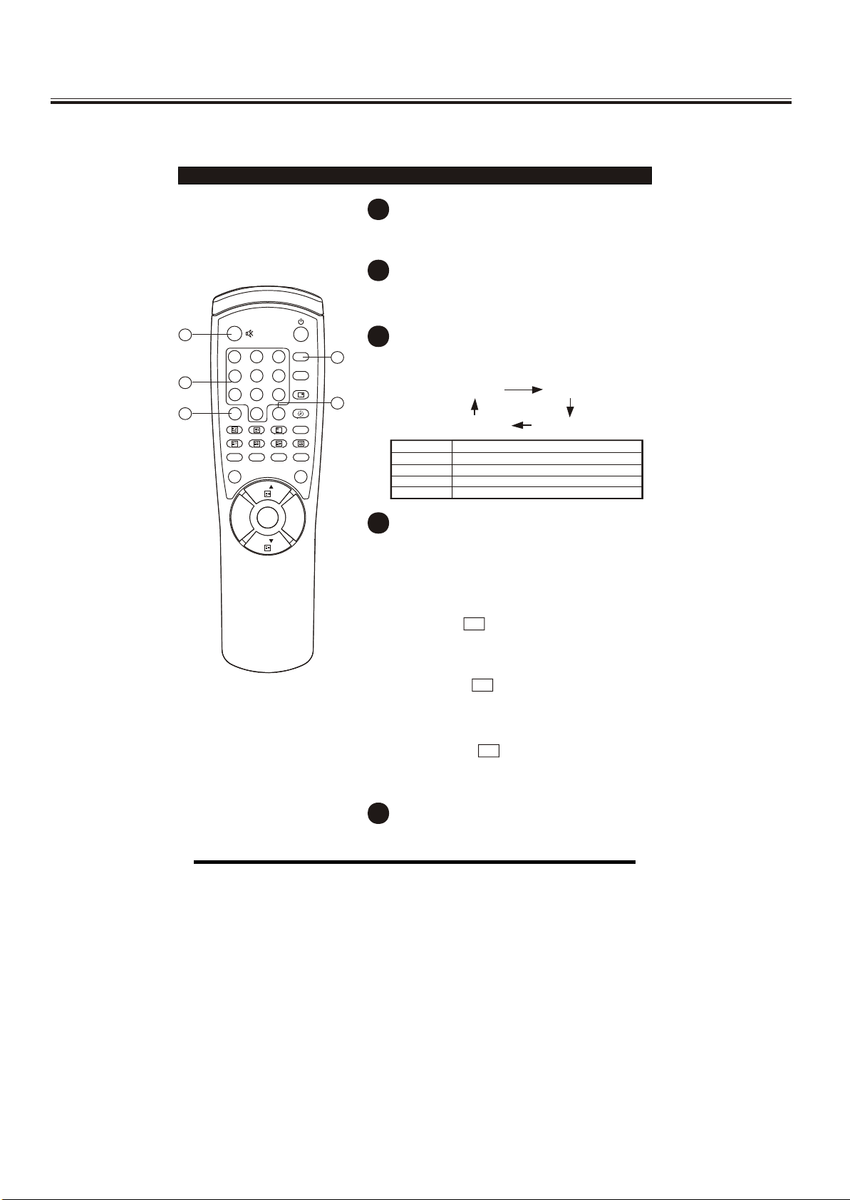
7
MUTE button
Press once to mute the sound. Press again
to restore the sound volume.
8
QUICK VIEW
button
Press this button to return to the previously
viewed program.
9
PICTURE MODE PICTURE MODE button
99
Press this button to select the desired
picture mode.
CUSTOM RICH
88
STANDARD SOFT
Picture Mode Description
CUSTOM
SOFT
STANDARD
RICH
10
DIGIT button
User preset picture mode.
Low contrast and low brightness level.
Middle contrast and middle brightness level.
High contrast and high brightness level.
This TV allows you to select channels from
0 to 255.
Press this button to select one-digit, twodigit or three-digit channels input options.
To select a one-digit channel (e.g. Channel
8), press this button to change
--/---
channel selection to "-" on screen display
and press the "8" button only.
To select a two-digit channel (e.g. Channel
28), press this button to change
--/---
channel selection to "--" on screen display
and press "2" and "8" buttons.
To select a three-digit channel (e.g. Channel
128), press this button to change
--/---
channel selection to "---" on screen display
and press "1" , "2"and"8" buttons.
11
CHANNEL SELECTION buttons
Press the number buttons to select a channel.
-20-
Page 21

Operation Instructions
Remote Control Unit
1
2 3
4
5
7
8
- /- -
0
MIX INDEX LANGUAGE
REVEAL SIZE SUB. PAGE
1414
1212
AV OK
CH
MENUMENU VOL.+VOL.-
CH
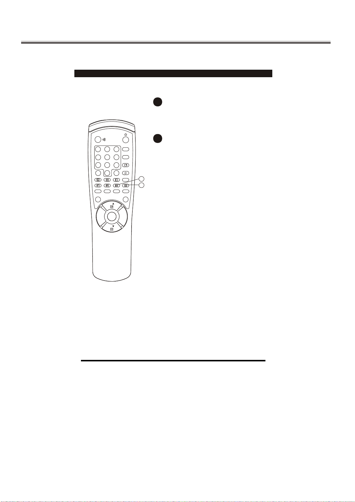
12
MENU button
Press this button to enter the menu screens
for various optional adjustable settings.
13
OK button
Press the button to sure the selected item or
enter the submenu.
P.M .
SYS
6
9
Q.
VIEW
XX
I/II
HOLD
14
AV button
1515
Press this button to switch between TV
broadcasts and AV input programs.
TV VIDEO S-VIDEO
VGA SCART
1313
15
RECALL
button
Press this button to display the settings on
the screen. (e.g. Channel number, system)
-21-
Page 22

Operation Instructions
TELETEXT OPERATIONS
For models with Teletext function only.
This page shows the function of the buttons on the remote control unit when
in Teletext mode.
1
33
55
11
77
44
88
2 3
4
5
7
8
- /- -
0
MIX INDEX LANGUAGE
REVEAL SIZE SUB. PAGE
AV OK
22
P.M .
SYS
6
9
Q.
VIEW
XX
I/II
HOLD
CH
MENUMENU VOL.+VOL.-
CH
1
MIX
button
Press this button to enter Teletext mode.
Press this button the second time to
mix mode.
Press this button again to exit .
+
TELETEXT PAGE UP
2
/ DOWN
-
CH
buttons
CH
Press these buttons to increase or decrease
the Teletext page number.
3
66
PAGE NUMBER SELECTION buttons
Press the number buttons to select a
Teletext page number.
4
COLOUR buttons
Press these buttons to access directly to
the corresponding pages displayed at the
lower part of the Teletext screen.
5
INDEX button
Press this button to go to the index page.
6
LANGUAGE button
Press this button to select the Teletext language
group.
7
REVEAL button
Press this button to reveal the hidden
information for some Teletext pages (e.g.
answers to puzzles or riddles). Press again
to hide the information.
8
SIZE button
Press this button to change the Teletext
screen display mode through the following:
- Upper half screen enlarged
- Lower half screen enlarged
- Normal screen state
-22-
Page 23
Operation Instructions
1
2 3
4
5
7
8
- /- -
0
MIX INDEX LANGUAGE
REVEAL SIZE SUB. PAGE
AV OK
P.M .
SYS
6
9
Q.
VIEW
XX
I/II
HOLD
CH
9
HOLD button
Press this button to hold the Teletext page
on display to prevent the page from changing.
Press again to release the hold state.
10
SUB.PAGE button
Some Teletext pages(e.g. P250)may contain
several sub-pages which are automatically
paged in a certain cycle by the TV station.
Press this button once, "P250/---" will be
displayed on screen. Enter number buttons
1010
99
(0-9) to look for other sub-pages if available.
If there is no sub-pages,the screen will be
displayed. Press this button again to
cancel.
MENUMENU VOL.+VOL.-
CH
-23-
Page 24
Operation Instructions
2 3
5
6
9
8
7
0
MENUMENU VOL.+VOL.-
I/II
P.M .
AV OK
SYS
Q.
VIEW
CH
CH
XX
MIX INDEX UPDATE
REVEAL SIZE SUB. PAGE
4
1
HOLD
- /- -
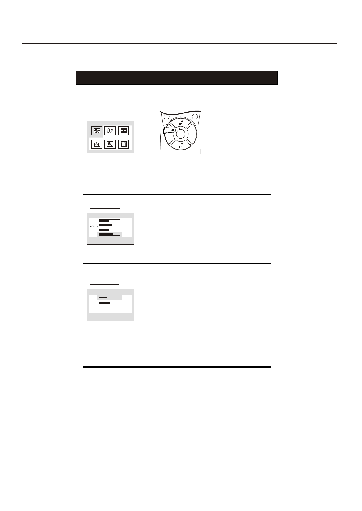
MENU SCREENS
This TV set allows you to adjust any settings by selecting from the menu screens.
Menu button
Picture
Press this button to display main menu, including Picture, Sound, Setup, Tune, VGA set and
Exit. You can select them by pressing the VOL+/- buttons, and enter the submenu by pressing
OK menu. The selected item will change to red.
Picture menu
Picture
Bri
Col
Shp
48
60
50
2
Enter Picture menu, you can select Bright, Contrast,
Colour, Sharpness and Hue(if NTSC system) items by
pressing PROG+/- Buttons. You can adjust the item
selected by pressing VOL+/-.The adjusted level is
stored in Custom mode.
Sound menu
Sound
Vol
Bal
35
50
Enter the Sound menu, you can adjust Volume and
Balance by pressing VOL+/-.
-24-
Page 25

Operation Instructions
Setup menu
Setup
Input select
Language
Factory Reset
Hpos
Vpos
Input Select menu
InPut Select
TV
Video
S-Video
Scart
VGA
Tune menu
32
50
Enter this menu, you can select Input Select
,Language ,Factory Reset ,H position and V position
items by pressing PROG+/- buttons. You can adjust
the H position and V position to change the OSD
position on screen by pressing VOL+/- buttons, or
enter the submenu of the Input Select, Language and
Factory Reset items by pressing OK button.
In this menu you can select the signal source, TV,
VIDEO, S-VIDEO, SCART or VGA.
In this menu you can complete the tune function.
Tune
Program
Skip
Band
MST
Search
Auto Search
Sound SYS
1
OFF
V-L
49.75MHZ
I
Select the Sound SYS, adjust the item to correct
system, then select the Auto item and press OK button
to begin search program. After finished search, the
program will back to NO.0 the picture will appear the
sound will be out.
1. Program
In this item, you can store the program number which are watching, and change
the number by VOL+/-.
2. Skip
You can set ON by VOL+/- buttons if you want to cancel the channel number
which you are watching.
3. Band
You can select V-L, V-H or UHF.
4. MST
To tune in weak station this item must be used.
5. Search
Press VOL+/- buttons to start searching. The VOL- button decrease the frequency,
the VOL+ button increase the frequency.
6. Auto
Press OK button to start search program automatically from V-L to UFH, the
searched program will be stored orderly.
7. Sound SYS
You can select BG, DK, I or M.
-25-
Page 26

Operation Instructions
VGA SET menu
Setup
Auto Config
Clk
Phs
Hpos
Vpos
This menu is only for PC monitor mode (VGA input).
1. Auto Config
Select auto config to adjust the screen position
automatically. It need a few seconds, in this time the
screen will black.
2. Clk
Press the VOL+/- to minimize any bertical bars or
stripes visible on the screen background.
3. Phs
When necessary, adjust the pixel phase of the
picture to avoid picture interference.
4. Hpos/Vpos
Press the VOL+/- buttons to adjust the picture
Horizontal and Vertical position.
Monitor Display modes
MODE
VGA
SVGA
XGA
Resolution
640X480
800X600
1024X768
Horizontal
Frequency(KHZ)
31.5KHz
37.7KHz
37.5KHz
37.9KHz
48.1KHz
46.9KHz
48.4KHz
56.5KHz
60.0KHz
64.0KHz
Vertical
Frequency(KHZ)
60Hz
72Hz
75Hz
60Hz
72Hz
75Hz
60Hz
70Hz
75Hz
80Hz
Note:
1.If the set is cold, there may be a small "flicker" when the set is switched on. This is
normal,There is nothing wrong with the set .
2.If possible , use the VESA 1024X768@60HZ video mode to obtain the best image
quality for your LCD monitor. If used under the other resolutions some scaled or
processed pictures may appear on the screen. The TV has pre-adjusted to the mode
VESA 1024X768@60HZ.
3. Some dot defects may appear on the screen ,like red. green or blue. Spots,
However, this will have no impact or effect on the monitor performance.
4. Do not press the LCD screen with your finger for a long time as this may incur
some after Images.
-26-
Page 27

Cabinet Parts List
Key No. Part No. Description
1 1007-15L010-01 POWER KNOB HOLDER LENS
2 1008-15L01M-01 CONTROL KEY KNOB - #MSG001
3 1001-15L01M-01 FRONT CABINET - #MSG001 FOR 8T81
4 1009-15L01M-01 POWER KNOB - #MSG001
5 1213-15L010-01 INLAY (A) - VGA INPUT COVER #MSG001 ENG (PVC)
6 1213-15L010-02 INLAY (B) - BACK AV JACK COVER #MSG001 ( 8T81)ENG FOR SCART PVC
7 1002-15L01M-01 BACK CABINET - #MSG001
8 0601-15L010-01 BACK LABEL ENG (8T81)
9 0806-RC0800-03 HANDSET - 33 KEYS FOR (8T81)
3
4
3
1
2
5
6
R
L Y
PHONE
PC A.IN
9
CB CR
S-VIDEO
ANT IN
R
7
8
L
VIDEO
-27-
Page 28

4321
D
C
B
Top Level
Top Level_1
D
C
B
A
1 2 34
PDF 文件使用 "pdfFactory" 试用版本创建 www.fineprint.com.cn
Title
NumberRevisionSize
B
Date:10-Jun-2004Sheet of
File:C:\DOCUME~1\ADMINI~1\LOCALS~1\Temp\Rar\NEW SKY5020.DDBDrawn By:
A
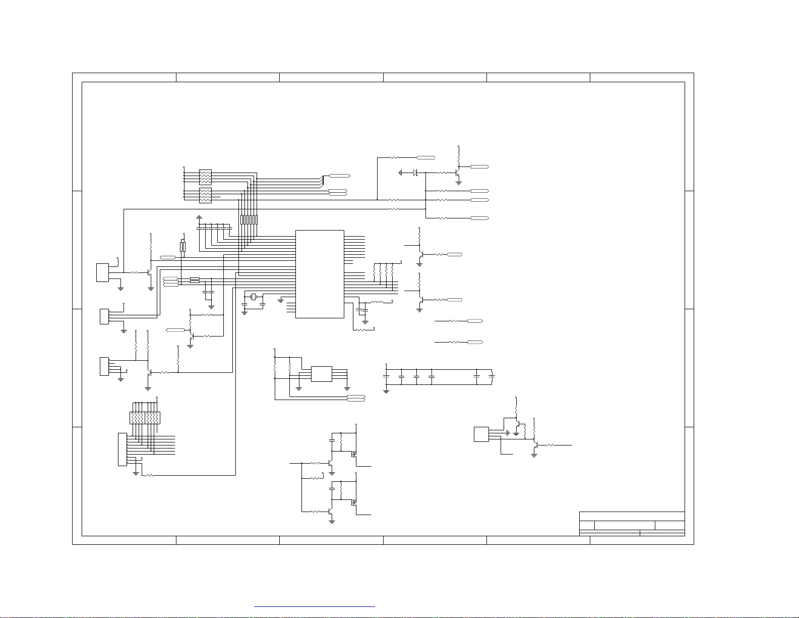
Page 29

D
C
Sheet 99.tuner
TV-CVBS
SIF
AM
7
8
10.audio
Sheet 10
B
Sheet 11. Input Connectors
AV-CVBS
S-C
TV-CVBS
10
11
12
13
S-C
AV-CVBS
Sheet 22. Video Decoder
Sheet 3
DDC_SDA
SC-G G
S-Y
S-Y
SC-G G
3. MCU
GPIO[0..7]
HDATA[0..3]
/PANEL_EN
VGA-R
VGA-G
VGA-B
+5V
RXC+
RXCRX2+
RX2-
SC-CVBS
SC-R R
SC-B B
SC-B B
SC-R R
SC-CVBS
SCL
SCL
SDA
/RESET
HFS
HCLK
/IRQ
LVDS_EN
4321
Sheet 44. gm5020
VGA-R
VGA-G
VGA-B
VS
VS
HS
HS
+5V
RXC+
RXCRX2+
RX2RX1+
RX1RX0+
RX0-
HS
VS
DDC_SCL
DDC_SDA
VCLK
YUV[0..7]
VGA-R
VGA-G
VGA-B
VS
HS
+5V
RXC+
RXCRX2+
RX2RX1+
RX1RX0+
RX0-
HS
VS
DDC_SCL
DDC_SDA
VCLK
YUV[0..7]
3
SCL
SDA
/RESET
GPIO[0..7]
HDATA[0..3]
HFS
HCLK
/IRQ
/PANEL_EN
LVDS_EN
/RESET
GPIO[0..7]
HDATA[0..3]
HFS
HCLK
/IRQ
DCLK
DVS
DHS
DEN
DARED[0..7]
DAGRN[0..7]
DABLU[0..7]
DBRED[0..7]
DBGRN[0..7]
DBBLU[0..7]
FSDATA[0..47]
FSADDR[0..13]
FSCLK
FSCKE
FSRAS
FSCAS
FSWE
FSDQM0
FSDQM1
FSDQM2
FSDQM3
DCLK
DVS
DHS
DEN
DARED[0..7]
DAGRN[0..7]
DABLU[0..7]
DBRED[0..7]
DBGRN[0..7]
DBBLU[0..7]
/PANEL_EN
LVDS_EN
FSDATA[0..47]
FSADDR[0..13]
FSCLK
FSCKE
FSRAS
FSCAS
FSWE
FSDQM0
FSDQM1
FSDQM2
FSDQM3
Sheet 7
DCLK
DVS
DHS
DEN
DARED[0..7]
DAGRN[0..7]
DABLU[0..7]
DBRED[0..7]
DBGRN[0..7]
DBBLU[0..7]
/PANEL_EN
LVDS_EN
5.teletext
Sheet 8
FSDATA[0..47]
FSADDR[0..13]
FSCLK
FSCKE
FSRAS
FSCAS
FSWE
FSDQM0
FSDQM1
FSDQM2
FSDQM3
6. Frame Store
Sheet 9
7. Power
Sheet 10
D
C
B
A
1 2 34
PDF 文件使用 "pdfFactory" 试用版本创建 www.fineprint.com.cn
8.LVDS
Title
NumberRevisionSize
Orcad A
Date:10-Jun-2004Sheet of
File:C:\DOCUME~1\ADMINI~1\LOCALS~1\Temp\Rar\NEW SKY5020.DDBDrawn By:
A
Page 30

4321
D
C
Input boards
BLUEREDRED+
BLUE+
HS
B
Input Connectors
BLUE-
RED-
RED+
BLUE+
HS
A
GREEN+
GREEN-
VS
RX1+
BLUEREDRED+
BLUE+
HS
GREEN+
GREENVS
RX1+
Input Connectors
1 2 34
GREEN+
GREENVS
RX1+
Input boards
RX0+
RX1RX2-
RX2+
RXC-
RXC+
RX0DDC_SDA
DDC_SCL
RX0+
RX1RX2-
RX2+
RXC-
RXC+
RX0-
DDC_SDA
DDC_SCL
RX0+
RX1RX2RX2+
RXCRXC+
RX0DDC_SDA
DDC_SCL
Title
NumberRevisionSize
B
Date:10-Jun-2004Sheet of
File:C:\DOCUME~1\ADMINI~1\LOCALS~1\Temp\Rar\NEW SKY5020.DDBDrawn By:
D
C
B
A
PDF 文件使用 "pdfFactory" 试用版本创建 www.fineprint.com.cn
Page 31

D
C
B
AVIN
J120
S-VID
LFA30_2A_103MHZ
JP120
AL-I
SC-Test
AR-I
CVBS-I
GND
R
B
G
SC-ID
CVBS-O
AR-O
AL-O
SCART
L129LFA30_2A_103MHZ
L130LFA30_2A_103MHZ
L141
654321
L120
C120
C124
10pF
10pF
6
8
2
20
5
15
7
11
16
19
CVBS-O
1
3
L121
C121
10pF
L122
C122
10pF
L123
C123
10pF
L125
C132
10pF
L126
C133
10pF
L127
C134
10pF
L128
C135
10pF
L131
C140
10pF
L132
C141
10pF
C125
10pF
C126
10pF
C127
10pF
C136
10pF
C137
10pF
C138
10pF
C139
10pF
C144
10pF
C145
10pF
L1333.3uH
C142
10pF
L1343.3uH
C143
10pF
L1423.3uH
C156
10pF
SC-L
R120
4.7K
C131
C130
10pF
SYS M SW
P/N P SW
SC-Test
SC-ID
RST-3415
AV-CVBS
TV-CVBS
SC-CVBS
SC-B B
SC-G G
SC-R R
SYS SW0
SYS SW1
+12V
HP-O/F
L136 C150
10pF
L137
LFA30_2A_103MHZ
L138
22uF/16V
+
+5V+5V
S-C
S-Y
SCL
SDA
+
OH-L
C155
R136
1000uF/16V
150
+
AVIN
C153
1000uF/16V
OH-R
C154
10pF
C159
10pF
AV-L
R138
100K
AV-R
R140
100K
C151
R137
10pF
150
L1393.3uH
C152
10pF
L1403.3uH
C158
10pF
D
C
B
SC-Test
R121
4.7K
SC-R
R122
4.7K
SC-CVBS
R123
75
SC-R R
R128
75
SC-B B
R129
75
SC-G G
R130
75
SC-ID
R131
4.7K
SC-RO
R132
4.7K
SC-LO
R133
4.7K
C146
10pF
C147
10pF
C157
10pF
AV-CVBS
R134
75
S-C
R135
75
S-Y
R139
75
CVBS-SC CVBS-O
+33V
CN120
J121
AV-IN
C129
10pF
CP700
HEADER 19X2
1
2
3
4
5
6
7
8
9
10
11
12
13
14
15
16
17
18
192120
C148
10pF
C149
10pF
56
LFA30_2A_103MHZ
L135
34
12
7
L124
38
37
36
35
34
33
32
31
30
29
28
27
26
25
24
23
22
A
1 2 3 4 56
PDF 文件使用 "pdfFactory" 试用版本创建 www.fineprint.com.cn
Title
NumberRevisionSize
C
Date:10-Jun-2004Sheet of
File:C:\DOCUME~1\ADMINI~1\LOCALS~1\Temp\Rar\NEW SKY5020.DDBDrawn By:
A
Page 32
654321
L029120Z/100M
L028120Z/100M
D
CN002
1
R
5
GND
2
G
4
DDC5V
3
B
6
GND
15
CLK
7
GND
12
DATA
10
GND
11
NC
8
GND
9
NC
14
VSYNC
13
HSYNC
C
CN001
1
B
2
3
4
L027120Z/100M
IC002
24C02
8
5
6
4
SCL
SDA
VCC
GND
TEST7NC13NC22NC3
1
IC001A
1 2
74LV14
IC001C
5 6
74LV14
C006
0.1uF
1206
16V
L030
VGA-R
VGA-G
VGA-B
R025
R024
4.7K
C001
+
47uF/16V
3 4
9 8
C005
0.1uF
1206
16V
R023
4.7K
CP002
IC001B
74LV14
74LV14
C002
0.1uF
IC001D
1
5V
2
10
11
3
4
5
6
7
8
9
CP001
3.3V
GND
VSYNC
HSYNC
GND
B
GND
G
GND
R
1
2
3
4
L026
VS
HS
CP001
ADJUST
MENU
PC/TV
2.0*10(90)
CP001
2.0*4(90)
VOL-
VOL+
1
2
CH-
3
4
CH+
5
6
7
8
GND
9
5V
10
IR
C001
0.1uF
LEDG
ONOFF
LEDR
C002
10uF_6V
LED001
4
3
GND
2
1
S005
LED002
4.7K
R020
R019
4.7K
4.7K
C004
C003
100P
100P
1608
L031
1608
S007
S006
S005
S004
S003
S002
S001
IC001
3
VCC
1
DAT
2
GND
IRRCVR
D
C
B
A
1 2 3 4 56
PDF 文件使用 "pdfFactory" 试用版本创建 www.fineprint.com.cn
Title
NumberRevisionSize
B
Date:10-Jun-2004Sheet of
File:C:\DOCUME~1\ADMINI~1\LOCALS~1\Temp\Rar\NEW SKY5020.DDBDrawn By:
A
Page 33
4321
D
C
B
m3230
VCLK
SDA
m3230
VCLK
SDA
YUV[0..7]
SCL
/RESET
YUV[0..7]
YUV[0..7]
SCL
/RESET
D
C
B
A
1 2 34
PDF 文件使用 "pdfFactory" 试用版本创建 www.fineprint.com.cn
Title
NumberRevisionSize
B
Date:10-Jun-2004Sheet of
File:C:\DOCUME~1\ADMINI~1\LOCALS~1\Temp\Rar\NEW SKY5020.DDBDrawn By:
A
Page 34
87654321
CVBS-OUT
RST-3230
D
TV-CVBS
TT-SYNC
SC-CVBS
SC-G G
C
B
SC-B B
SC-R R
TT-G
TT-B
TT-R
TT-FB
C719
3.3pF
C720
3.3pF
SDA
SCL
S-C
S-Y
CVBS-OUT
RESETQ
SDA
R700100
SCL
R701100
C701100P
C702100P
TV-CVBS
C700
0.68uF
S-C
S-Y
SC-CVBS
SC-G G
SC-B B
SC-R R
C711
TT-G
0.22uF
C712
TT-B
0.22uF
C713
TT-R
0.22uF
R702100
C703
0.68uF
C704
1nF
C714
0.68uF
C715
0.68uF
C716
0.22uF
C717
0.22uF
C718
0.22uF
X700
20.25M
R707
1K
13
14
74
VIN3
SCL
SDA
73
VIN2
71
CIN
72
VIN1
75
VIN4
5
Y2/G2
4
U2/B2
6
V2/R2
2
Y1/G1
1
U1/B1
3
V1/R1
79
FBIN1
62
XTALI
63
XTALO
CLK 560FPDA T58CLK 2024ASGND7ASGND64GND11APGND25APVDD26PLGN D30YGND35CGND46SPGN D51AFGND65ISGND68ISGND77ISGND80I2C SEL
C705
1nF
V33
C706
0.22uF
70
15
10
12
VDD
RST #
VOUT
VDDCA P9GNDCA P
IC700
VPC3230D
ADR:0X88
C722
47nF
C721
1nF
V33 VCCA
29
45
52
YVDD36CVDD
SPVD D
PLVD D
69
76
59
78
VREF
VRT
ISVDD
AFVDD
VSTB Y
FFIE
FFWE
FFRST
FFRE
FFOE
Y7
Y6
Y5
Y4
Y3
Y2
Y1
Y0
UV7
UV6
UV5
UV4
UV3
UV2
UV1
UV0
LLC2
LLC
HS
INTLC
AVO
HCLP
VS
TEST
VGAV
OE#
67
VREF1
66
VRT1
47nF
19
20
21
22
23
RP700
31
32
33
34
37
38
39
40
41
42
43
44
47
48
49
50
27
28
56
53
54
55
57
16
17
18
8
I11O1
2
7
47
I2
O2
3
6
I3
O3
5
I44O4
RP701
47
RP702
RP703
47
47
R70347
R7040_NS
R70547
R70647
10uF_E
YUV7
YUV6
YUV5
YUV4
YUV3
YUV2
YUV1
YUV0
C709
C710
47nFC707
10uF_EC708
YUV[0..7]
VCLK
VCLK
+33V
1
2
3
4
5
6
7
8
9
10
11
12
13
14
15
16
17
18
19
CN700
HEADER 19X2
38
SYS M SW
37
P/N P SW
36
SC-Test
35
SC-ID
34
+5V+5V
33
32
S-C
31
S-Y
30
AV-CVBS
29
TV-CVBS
28
SC-CVBS
27
SC-B B
26
SC-G G
25
SC-R R
24
SCL
23
SDA
22
SYS SW0
21
SYS SW1
20
+12V
D
C
B
+5V
VCCA
The bypass caps above are for analog supply pins
(pin 69 and 76) of U1 VPC3230D decoder
A
1 2 3 4 5 6 78
FERRITE BEAD
C723
0.22uF C731
VCCA
L700
C727
22uF_E
VCCA
VCCA
C726
C725
C724
1nF
0.22uF
1nF
+3.3V
L701
FERRITE BEAD
V33
C732
C728
22uF_E
0.1uF
The bypass caps above are for digital supply pins
(pin 29,36,45,52) of U1 VPC3230D decoder
V33
C730
C729
0.1uF
0.1uF
PDF 文件使用 "pdfFactory" 试用版本创建 www.fineprint.com.cn
C733
0.1uF
0.1uF
A.1
A
9
SKYWORTH MULTIMEDIA R&D
Title
Main BOARD ( VPC3230 main picture)
NumberRevisionSize
A3
Date:10-Jun-2004Sheet of
File:C:\DOCUME~1\ADMINI~1\LOCALS~1\Temp\Rar\NEW SKY5020.DDBDrawn By:
900-XXXX-XX 01
1
HGW
Page 35
4321
D
C
B
D
C
B
MCU
/PANEL_EN
A
/IRQ
HCLK
/RESET
HFS
/PANEL_EN
/IRQ
HCLK
/RESET
HFS
MCU
1 2 34
LVDS_EN
GPIO[0..7]
HDATA[0..3]
SDA
SCL
GPIO[0..7]
HDATA[0..3]
LVDS_EN
GPIO[0..7]
HDATA[0..3]
SDA
SCL
PDF 文件使用 "pdfFactory" 试用版本创建 www.fineprint.com.cn
Title
NumberRevisionSize
B
Date:10-Jun-2004Sheet of
File:C:\DOCUME~1\ADMINI~1\LOCALS~1\Temp\Rar\NEW SKY5020.DDBDrawn By:
A
Page 36
654321
D
+5VC +5VC
12
R502
R503
1 2
10K
TXD
RXD
+12V
12
+12V
10K
SYS M SW
RESET
3
1
SDA
Q500
2
SCL
BC848
P/N P SW
+5VC
STANDBY
12
R512
R511
10K
unused
3
R514
Q504
1
BC848
10K
2
C
B
IC503
VCC
RSTN
GND
DS1813
Reset Circuit
CN502
RS-232S
CN500
BLON
NC
BLC
GND
+12V
Backlight Connector
+5VC
2
1
/RESET
3
+5VC
1
2
3
4
1
2
3
4
5
+5VC
182736
45
182736
45
RN504
10K
KEY_LEFT
KEY_RIGHT
KEY_UP
KEY_DOWN
KEY_MENU
KEY_AV/TV
KEY_OK
+5VC
R508
12
100
KEY_LEFT
KEY_RIGHT
KEY_UP
KEY_DOWN
MENU
AV/TV
STANDBY
GND
+5V
IR
RN502
10K
CN501
Keypad & IR
10
9
8
7
6
5
4
3
2
1
A
1 2 3 4 56
D
+5VC
R507
1 2
10K
R516
1 2
10K
R517
1 2
10K
R519
1 2
10K
R527
4.7K
R530
4.7K
D5
1 2
1 2
D6
C503
0.1uF
12
R506
10K
3
RST-3415
1
Q502
BC848
2
RST-5020
RST-3230
RST_LVDS
12
SC-ID
12
SC-Test
MUTE
R531
10K_NS
L1-SW
R532
10K_NS
C508
C509
22uF/10V
22uF/10V
C
B
+5VC
R524
1K
+5VC
1 2
Q507
CN503
2.0*4(90)
BC848
4
LEDG
3
GND
2
ONOFF
1
LEDR
KEY_STB
R505
R523
1K
10K
1 2
1 2
R504
Q506
BC848
12
/BKLT_EN
10K
A
Title
NumberRevisionSize
Orcad C
Date:10-Jun-2004Sheet of
File:C:\DOCUME~1\ADMINI~1\LOCALS~1\Temp\Rar\NEW SKY5020.DDBDrawn By:
R513
1 2
L902*
22uH
C507
22uF/10V
12
R543
4.7K
+5VC
R544
4.7K
12
0-NS
R520
1 2
1K
R521
1 2
0-NS
R547
4.7K
12
12
+5VC
C504
0.1uF
+5VC
C500
22uF/10V
R546
4.7K
12
+5VC
RN50110K
1 8
2 7
3 6
4 5
RN503
1 8
2 7
3 6
4 5
10K
C510
C512
C511
C513
100P
C514
C515
100P
100P
R526
R529
10K
10K
R540
R541
C517
220P
+5VC
12
R522
10K
3
Q503
BC848
+5VC
2
12
R533
4.7K
100P
200
200
R542
1 2
10K
R515
1
10K
100P
100P
C516
220P
12
12
HDATA0
HDATA1
HDATA2
HDATA3
HCLK/SCL
HFS/SDA
/IRQ
/RESET
R53 420 0
R53 520 0
R53 620 0
R53 720 0
R53 820 0
R53 920 0
IC501
2
HDATA0
P1.0/T2
3
HDATA1
P1.1/T2EX
4
HDATA2
P1.2/ECI
5
HDATA3
P1.3/CEX0
6
HCLK/SCL
P1.4/CEX1
7
HFS/SDA
P1.5/CEX2
8
STANDBY
P1.6/CEX3/WAIT#
9
SYS M SW
P1.7/CEX4/A17/W
10
RST
11
RXD
P3.0/RXD
13
TXD
P3.1/TXD
14
REMOTE
P3.2/INT0#
/IRQ
15
P3.3/INT1#
16
SDA
P3.4/T0
SCL
17
P3.5/T1
18
P/N P SW
P3.6/WR#
/BKLT_EN
19
P3.7/RD#/A16
20
XTAL2
XTAL2
XTAL1
21
XTAL1
22
X500
24MHz
C506
C505
22P
22P
VSS
1
NIC
12
NIC
23
NIC
34
NIC
89C738
+5VC
12
12
R500
R501
10K
10K
SCL
SDA
HDATA[0..3]
HCLK
HFS
24
KEY_OK
A8/P2.0
25
KEY_AV/TV
A9/P2.1
26
A10
A10/P2.2
27
KEY_MENU
A11/P2.3
28
KEY_DOWN
A12/P2.4
29
KEY_UP
A13/P2.5
30
KEY_RIGHT
A14/P2.6
31
KEY_LEFT
A15/P2.7
32
PSEN#
33
ALE/PROG#
36
D7
AD7/P0.7
D6
37
AD6/P0.6
38
D5
AD5/P0.5
39
KEY_STB
AD4/P0.4
40
LVDS-ON
AD3/P0.3
TT-S1
41
AD2/P0.2
42
TT-S2
AD1/P0.1
SCREEN-ON
43
AD0/P0.0
44
VCC
35
EA#/VPP
R509
0
GND External Program Memory
+5V Internal Program Memory
IC500
8
7
6
5
1
A0
VCC
2
A1
WP
3
A2
SCK
VSS4SI
24C08
SCL
SDA
/IRQ
D500
3.3V
+5VC
12
R525
10K
A10
Q501
+5VC
BC848
+5VC
12
R528
10K
D7
Q505
BC848
C502
C501
0.1uF
0.1uF
+5V
12
R906
C921
3.3K
0.1uF
IC909-1
IRF7314
Q902
BC848
+12V
12
R905
C920
3.3K
0.1uF
IC909-2
IRF7314
Q901
BC848
REMOTE
SCREEN-ON
R907
1 2
3.3K
R909
1 2
3.3K
R908
1 2
3.3K
+5V
PDF 文件使用 "pdfFactory" 试用版本创建 www.fineprint.com.cn
Page 37
654321
D
C
B
tvt03aa
tvt03aa
D
C
B
A
1 2 3 4 56
PDF 文件使用 "pdfFactory" 试用版本创建 www.fineprint.com.cn
Title
NumberRevisionSize
B
Date:10-Jun-2004Sheet of
File:C:\DOCUME~1\ADMINI~1\LOCALS~1\Temp\Rar\NEW SKY5020.DDBDrawn By:
A
Page 38

654321
D
IC401
1
BI0
2
BI2
3
BCOM
4
C
SYS SW1
SYS SW0
SC-CVBS
TV-CVBS
B
S-Y
BI3
5
BI1
6
INHBIT
7
VEE
8
GND
HEF4052
22uF_E
C418
470N
+3.3V L402
+3V3D
C406
C407
0.1uF
+5VF +3V3D +3V3A
5
33
VDD5V1
20
VIDEOIN
11
VINP
8
VREFP
9
VREFN
2
SCL
3
SDA
37
PLLRC1
45
PLLRC2
41
OSCIN
42
OSCOUT
15
VBG
16
VCM
4
TDO
13
NC
GND5V1
23
48
+5VF
L400
FERRITE BEAD
+5VF
C435
0.1uF
C736
L702
100uF
12UH
16
VDD
15
AI2
14
AI1
13
ACOM
12
AI0
11
AI3
10
CONB
9
CONA
C431
22uF
C432
22uF
C433
22uF
VCCA
VCCA
+5V
C436
22uF
R435
1K
R434
1K
R431
100K
R432
100K
R433
100K
R437
R438
240
5.1K
R436
100
R441
R439
200
3.3K
C434
100uF
C400
22uF_E
Q402
BC848
C402
0.1uF
C401
0.1uF
Q401
BC858
R440
100
R430
470
SCL
SDA
C419
2.2N
+3.3V
+3V3A
C403
22uF_E
VCCA
+3V3A
C415
C413
100P
C414
100P
R413100
R414100
R415
100
C422
C420
C421
22N
22N
2.2N
L401
FERRITE BEAD
C404
0.1uF
C416
22uF
22uF
R416
150
C423
33P
+3V3A
C405
0.1uF
C4240.1uF
X40013.875MHz
C425
33P
C427
0.1uF
C429
0.1uF
R405
1K
R406
1K
C417
0.1uF
C428
0.1uF
FERRITE BEAD
C408
0.1uF
39
VDD5V2
GND5V2
GND3V1A
36
35
+3V3D+5V
C409
C410
0.1uF
0.1uF
22
17
10
47
43
VDDA1
VDD3V5
VDD3V4
VDD3V346VDD3V2
VDD3V1B38VDD3V1A
GND3V4
GND3V1B
GNDA1A
GND3V5
GND3V2
GND3V3
6
7
12
34
40
44
C412
C411
0.1uF
0.1uF
21
31
MUTE
VDDA3
VDDA2
RED
GREEN
BLUE
BLANK
SYNC
RSTB
STDBYM
TSTIO
FLAG1
FLAG2
CS0
CS1
SCEN
TSTAPP
GNDA3
GNDA1B
GNDA2
IC400
TVT0310A
18
14
R400
30
29
28
27
19
C426
32
0.1uF
24
R420
25
10K
50
51
52
1
26
R4170-NS
R4180
49
R4190-NS
R4270
R401
1K
390
R407
R408
1K
390
R421
R423
1K
1K
R422
R428
10K
R442
+5VF
100
+5VF
TT-R
TT-G
TT-FB
390
TT-B
VCCA
Q403
BC848
R443
47
TT-SYNC
R444
75
D
C
B
A
1 2 3 4 56
PDF 文件使用 "pdfFactory" 试用版本创建 www.fineprint.com.cn
Title
NumberRevisionSize
B
Date:10-Jun-2004Sheet of
File:C:\DOCUME~1\ADMINI~1\LOCALS~1\Temp\Rar\NEW SKY5020.DDBDrawn By:
A
Page 39
4321
D
C
B
D
C
B
Frame Store
FSDQM0
FSDQM1
FSDQM2
FSDATA[0..47]
FSADDR[0..13]
FSDATA[0..47]
FSADDR[0..13]
A
FSDATA[0..47]
FSADDR[0..13]
FSDQM0
FSDQM1
FSDQM2
Frame Store
1 2 34
FSDQM3
FSRAS
FSCLK
FSCKE
FSCAS
FSWE
FSDQM3
FSRAS
FSCLK
FSCKE
FSCAS
FSWE
PDF 文件使用 "pdfFactory" 试用版本创建 www.fineprint.com.cn
Title
NumberRevisionSize
B
Date:10-Jun-2004Sheet of
File:C:\DOCUME~1\ADMINI~1\LOCALS~1\Temp\Rar\NEW SKY5020.DDBDrawn By:
A
Page 40
DVDD_3.3
C800
22uF/10V
654321
DVDD_3.3 DVDD_3.3
C803
C802
C801
0.1uF
0.1uF
C805
C804
0.1uF
220P
C807
C806
220P
22uF/10V
220P
C809
C808
0.1uF
0.1uF
C811
C810
0.1uF
C813
C812
220P
220P
220P
C814
22uF/10V
C815
C816
0.1uF
0.1uF
C819
C817
C818
C820
220P
0.1uF
220P
220P
D
FSDATA[0..47]
FSADDR[0..13]
FSCLK
FSCKE
FSRAS
FSCAS
FSWE
FSDQM0
FSDQM1
C
FSDQM2
FSDQM3
B
A
FSADDR0
FSADDR1
FSADDR2
FSADDR3
FSADDR4
FSADDR5
FSADDR6
FSADDR7
FSADDR8
FSADDR9
FSADDR10
FSADDR11
FSADDR0
FSADDR1
FSADDR2
FSADDR3
FSADDR4
FSADDR5
FSADDR6
FSADDR7
FSADDR8
FSADDR9
FSADDR10
FSADDR11
FSADDR0
FSADDR1
FSADDR2
FSADDR3
FSADDR4
FSADDR5
FSADDR6
FSADDR7
FSADDR8
FSADDR9
FSADDR10
FSADDR11
D
DVDD_3.3
25
13
VCC1VCC
VSS
26
VCC Q7VCC Q
VSS50VSSQ4VSSQ10VSSQ41VSSQ
44
2
FSDATA0
DQ0
3
DQ1
DQ2
DQ3
DQ4
DQ5
DQ6
DQ7
DQ8
DQ9
DQ10
DQ11
DQ12
DQ13
DQ14
DQ15
K4S161622
FSDATA1
5
FSDATA2
6
FSDATA3
8
FSDATA4
9
FSDATA5
11
FSDATA6
12
FSDATA7
39
FSDATA8
40
FSDATA9
42
FSDATA10
43
FSDATA11
45
FSDATA12
46
FSDATA13
48
FSDATA14
49
FSDATA15
37
NC
VCC Q38VCC Q
47
IC800
21
A0
22
A1
23
A2
24
A3
27
A4
28
A5
29
A6
30
A7
31
A8
32
A9
20
A10
19
A11
35
CLK
34
CKE
18
/CS
17
/RAS
16
/CAS
15
/WE
14
LDQM
36
UDQM
SDRAM SELECTION
SXGA 85Hz
DVDD_3.3
25
13
VCC1VCC
VSS
26
VCC Q7VCC Q
VSS50VSSQ4VSSQ10VSSQ41VSSQ
44
2
FSDATA16
DQ0
FSDATA17
3
VCC Q38VCC Q
DQ1
5
FSDATA18
DQ2
FSDATA19
6
DQ3
8
FSDATA20
DQ4
FSDATA21
9
DQ5
11
FSDATA22
DQ6
FSDATA23
12
DQ7
39
FSDATA24
DQ8
FSDATA25
40
DQ9
42
FSDATA26
DQ10
FSDATA27
43
DQ11
45
FSDATA28
DQ12
FSDATA29
46
DQ13
48
FSDATA30
DQ14
FSDATA31
49
DQ15
37
NC
47
K4S161622
IC801
21
A0
22
A1
23
A2
24
A3
27
A4
28
A5
29
A6
30
A7
31
A8
32
A9
20
A10
19
A11
35
CLK
34
CKE
18
/CS
17
/RAS
16
/CAS
15
/WE
14
LDQM
36
UDQM
DVDD_3.3
25
13
VCC1VCC
VSS
26
VCC Q7VCC Q
VSS50VSSQ4VSSQ10VSSQ41VSSQ
44
2
FSDATA32
DQ0
3
DQ1
DQ2
DQ3
DQ4
DQ5
DQ6
DQ7
DQ8
DQ9
DQ10
DQ11
DQ12
DQ13
DQ14
DQ15
K4S161622
FSDATA33
5
FSDATA34
6
FSDATA35
8
FSDATA36
9
FSDATA37
11
FSDATA38
12
FSDATA39
39
FSDATA40
40
FSDATA41
42
FSDATA42
43
FSDATA43
45
FSDATA44
46
FSDATA45
48
FSDATA46
49
FSDATA47
37
NC
VCC Q38VCC Q
47
IC802
21
A0
22
A1
23
A2
24
A3
27
A4
28
A5
29
A6
30
A7
31
A8
32
A9
20
A10
19
A11
35
CLK
34
C821
47pF
12
R800
75
CKE
18
/CS
17
/RAS
16
/CAS
15
/WE
14
LDQM
36
UDQM
DevicesInput Format
3 @ 1M x 16 SDRAM
2 @ 1M x 16 SDRAMXGA 85Hz
JP800
DVDD_3.3
RN800
1
2
3
4
5
6
7
8 9
10K
RN801
1
2
3
4
5
6
7
8 9
10K
NAME
USER_BITS(4:0)
Reserved
Reserved
HOST_PROTOCOL
USER_BITS(7:5)
OCM_START
OCM_EXTCLK
OCM_CLK
ADDR(6:0)
HOST_PROTOCOL
USER_BITS(7:5)
OCM_START
OCM_EXTCLK
OCM_CLK
DVDD_3.3
16
15
14
13
12
11
10
16
15
14
13
12
11
10
SET
SET
JP808
0
0
1
xFSADDR(10:8)
0
0
0
-
0
x
0
0
0
FSADDR0
FSADDR1
FSADDR2
FSADDR3
FSADDR4
FSADDR5
FSADDR6
FSADDR7
FSADDR8
FSADDR9
FSADDR10
FSADDR11
FSADDR12
FSADDR13
PLACE RN CLOSE TO MEMORY ICs
SIX-WIRE HOST INTERFACE SETTING
ADDRESS
FSADDR(4:0)x
FSADDR5
FSADDR6
FSADDR(7)
FSADDR11
FSADDR12
FSADDR13
TWO-WIRE HOST INTERFACE SETTING
ADDRESSNAME
FSADDR(6:0)
FSADDR(7)
FSADDR(10:8)
FSADDR11
FSADDR12
FSADDR13
JP802
JP801
231
231
JP809
JP810
231
231
Status Register ( Can be Used as Panel Selection )
Pull Low
Pull Low
Pull High ( Six Wires )
Status Register ( Can be Used as Panel Selection )
Pull Low
MCU Clock Select ( Default = 0 for INTCLK )
MCU Clock Select ( Default = 0 for RCLK/2 )
IIC Chip Address
Pull Low ( Two Wires )
Status Register ( Can be Used as Panel Selection )
Pull Low
MCU Clock Select ( Default = 0 for INTCLK )
MCU Clock Select ( Default = 0 for RCLK/2 )
231
231
DESCRIPTION
DESCRIPTION
JP806
JP805
JP804
JP803
231
231
JP812
JP811
231
231
JP807
231
231
JP813
231
C
231
B
A
1 2 3 4 56
PDF 文件使用 "pdfFactory" 试用版本创建 www.fineprint.com.cn
Title
NumberRevisionSize
Orcad C
Date:10-Jun-2004Sheet of
File:C:\DOCUME~1\ADMINI~1\LOCALS~1\Temp\Rar\NEW SKY5020.DDBDrawn By:
Page 41
4321
D
C
gm5020
GREEN-
B
FSDQM2
BLUE-
/RESET
DHS
YUV[0..7]
YUV[0..7]
DVS
FSCLK
VS
FSRAS
GREEN+
RED+
RXC+
/IRQ
REDDDC_SDA
DDC_SCL
HS
DAGRN[0..7]
HDATA[0..3]
DARED[0..7]
DBRED[0..7]
DBBLU[0..7]
DAGRN[0..7]
HDATA[0..3]
DARED[0..7]
DBRED[0..7]
DBBLU[0..7]
A
GREENFSDQM2
BLUE/RESET
DHS
YUV[0..7]
DVS
FSCLK
VS
DAGRN[0..7]
FSRAS
HDATA[0..3]
DARED[0..7]
HS
DBRED[0..7]
GREEN+
RED+
RXC+
DBBLU[0..7]
/IRQ
REDDDC_SDA
DDC_SCL
gm5020
1 2 34
HCLK
FSCKE
GPIO[0..7]
DBGRN[0..7]
DCLK
FSDQM1
FSDATA[0..47]
VCLK
FSWE
FSCAS
DEN
DABLU[0..7]
FSADDR[0..13]
RXCFSDQM3
FSDQM0
BLUE+
HFS
RX2RX0-
RX0+
RX1-
RX2+
RX1+
GPIO[0..7]
DBGRN[0..7]
FSDATA[0..47]
DABLU[0..7]
FSADDR[0..13]
HCLK
FSCKE
GPIO[0..7]
DBGRN[0..7]
DCLK
FSDQM1
FSDATA[0..47]
VCLK
FSWE
FSCAS
DEN
DABLU[0..7]
FSADDR[0..13]
RXCFSDQM3
FSDQM0
BLUE+
HFS
RX2RX0RX0+
RX1RX2+
RX1+
Title
NumberRevisionSize
B
Date:10-Jun-2004Sheet of
File:C:\DOCUME~1\ADMINI~1\LOCALS~1\Temp\Rar\NEW SKY5020.DDBDrawn By:
D
C
B
A
PDF 文件使用 "pdfFactory" 试用版本创建 www.fineprint.com.cn
Page 42

654321
DVDD_3.3 DVDD_3.3
C601
C600
0.1uF
0.1uF
DVDD_2.5
D
C619
22uF/10V
C620
22uF/10V
C604
C602
C603
0.1uF
0.1uF
0.1uF
C623
C622
C621
0.1uF
0.1uF
0.1uF
AVDD_2.5
C639
C638
0.1uF
0.1uF
C641
C640
C642
0.1uF
0.1uF
220P
AVDD_3.3
C650
C648
C649
C647
0.1uF
0.1uF
C651
0.1uF
0.1uF
0.1uF
PVDD_3.3
C659
C658
0.1uF
DVDD_3.3
C
C666
22uF/10V
+3.3V
L600
FERRITE BEAD
L601
FERRITE BEAD
L602
FERRITE BEAD
+2.5V
L603
FERRITE BEAD
L604
FERRITE BEAD
B
0.1uF
C667
22uF/10V
DVDD_3.3
PVDD_3.3
AVDD_3.3
DVDD_2.5
AVDD_2.5
C660
0.1uF
C668
22uF/10V
C661
0.1uF
C686
22uF/10V
C662
220P
C607
C605
C606
C608
C609
0.1uF
0.1uF
0.1uF
0.1uF
0.1uF
C626
C624
0.1uF
C627
C625
0.1uF
C628
0.1uF
0.1uF
0.1uF
AVDD_2.5
C643
C644
C645
220P
C683
220P
220P
22uF/10V
AVDD_3.3
C652
C653
220P
220P
C656
C655
C654
220P
C684
220P
220P
22uF/10V
PVDD_3.3
C665
C664
C663
220P
C685
220P
220P
22uF/10V
C612
C611
C610
220P
220P
220P
C631
C630
C629
220P
220P
220P
C614
RED+
GREEN+
BLUE+
C615
220P
220P
C634
C633
220P
220P
VGA-R
VGA-G
VGA-B
R612
R611
75
75
1 2
1 2
C613
220P
C632
220P
AVDD_3.3
C672
5P
C671
X600
5P
24MHz
R603
2.2K
1 2
VS
VS
HS
1 2
HS
C681
R614
1000P
100
A
1 2 3 4 56
C616
220P
DVDD_2.5
C635
220P
100
100
100
100
100
100
R610
75
1 2
XTAL
TCLK
1 2
C679
2200P
C682
1000P
1 2R604
1 2R605
1 2R606
1 2R607
1 2R608
1 2R609
AVDD_3.3
R613
100
YUV[0..7]
HDATA[0..3]
RST-5020
DVDD_3.3DVDD_2.5
C618
C617
220P
220P
C636
220P
VCLK
HCLK
AVDD_2.5
A6
A7
A8
A9
A10
A11
AVDD_3.3
B2
B6
B7
B8
B9
B11
C3
D3
E3
A2
A3
A4
B1
B3
B4
C4
C5
C7
C11
D4
D5
D7
D11
E4
PVDD_3.3
F2
F4
G1
G3
H1
F3
G2
G4
H2
C673
0.01uF
C674
0.01uF
C675
0.01uF
C676
0.01uF
C677
0.01uF
C678
0.01uF
TP601
TP602
R600
1.00K
C680
2200P
TP603
TP604
R602
10K
HFS
/IRQ
H3
K3
E1
RED+
E2
RED-
D2
GREEN+
D1
GREEN-
C1
BLUE+
C2
BLUE-
ADC_TEST
A1
TP600
C6
D6
C8
D8
C9
D9
C10
D10
A5
CLKOUT
VBUFC
B5
B10
12
REXT
1%
H4
XTAL
TCLK
K1
VSYNC
L2
HSYNC
F1
ANTEST
VDACP
K2
L3
EXTCLK
12
A12
B12
YUV7
C12
YUV6
A13
YUV5
B13
YUV4
C13
YUV3
A14
YUV2
B14
YUV1
C14
YUV0
G19
G18
L1
M1
M2
M3
M4
N1
P3
HDATA3
P4
HDATA2
R1
HDATA1
R2
HDATA0
P2
P1
R3
R4
T1
T2
N2
N3
J1
J3
J2
J4
IC600
AVDD_2.5
AVDD_2.5
AVDD_2.5
AVDD_2.5
AVDD_2.5
AVDD_2.5
AVDD_3.3
AVDD_3.3
AVDD_3.3
AVDD_3.3
AVDD_3.3
AVDD_3.3
AVDD_3.3
AVDD_3.3
AVDD_3.3
AGND
AGND
AGND
AGND
AGND
AGND
AGND
AGND
AGND
AGND
AGND
AGND
AGND
AGND
AGND
PLLVDD_3.3
PLLVDD_3.3
PLLVDD_3.3
PLLVDD_3.3
PLLVDD_3.3
PLLVDD_3.3
PLLVDD_3.3
PLLGND
PLLGND
PLLGND
PLLGND
PLLGND
PLLGND
PLLGND
RED+
REDGREEN+
GREENBLUE+
BLUEADC_TEST
RXC+
RXCRX0+
RX0RX1+
RX1RX2+
RX2-
CLKOUT
VBUFC
REXT
XTAL
TCLK
VSYNC
HSYNC
ANTEST
VDACP
EXTCLK
VCLK
YUV7
YUV6
YUV5
YUV4
YUV3
YUV2
YUV1
YUV0
GPIO7/DOVL
GPIO6/DFSYNCn
GPIO5/TXD
GPIO4/RXD
GPIO3/T1
GPIO2
GPIO1/PWM1
GPIO0/PWM0
HDATA3
HDATA2
HDATA1
HDATA0
HFS/SDA
HCLK/SCL
IRQn
IRQINn
RESETn
SCAN_TEST
DDC_SCL
DDC_SDA
gm5020
BGA292
D17
P17
F17
K17
D14
M17
T17
D12
U14
U16
U11
U7
U4
DVDD_ 2.5
DVDD_ 2.5
DVDD_ 2.5
DVDD_ 2.5
DVDD_ 2.5
DVDD_ 2.5
DVDD_ 2.5
DVDD_ 2.5
DVDD_2.5
DVDD_2.5
DVDD_2.5
DVDD_2.5U9DVDD_2.5N4DVDD_2.5
DVDD_2.5
gm5020
Analog Input
TMDS Receiver
PLL and DDS
Video Input
Host Interface
HDCP
DGN D
DGND
DGND
DGND
DGND
DGND
DGND
DGND
DGND
DGND
DGND
DGNDK9DGND
DGNDK8DGND
J8
J9
H8
H9
J10
J12
J13
J11
H13
H11
H10
H12
K10
R1 7
J17
N17
D16
L17
D15
E17
G17
K4
D13
DVDD_ 3.3
DVDD_ 3.3
DVDD_ 3.3
DVDD_ 3.3
DVDD_ 3.3
DVDD_ 3.3
DVDD_ 3.3
DVD D_2 .5
DVD D_3 .3
DGND
DGND
DGND
DGNDL8DGNDL9DGND
DGND
DGND
DGND
DGNDM8DGNDM9DGND
L10
L11
L12
L13
K12
K11
K13
L4
U15
U12
U10
U17
U13
U8
U6
T4
G20
DCLK
DCLK
F20
DHS
DHS
F19
DVS
DVS
DVD D_3 .3
DVDD_3.3
DVDD_3.3
DVDD_3.3
DVDD_3.3
DVDD_3.3
DVDD_3.3
Display Port
Frame StoreInterface
DGND
DGND
DGND
DGNDN9DGND
DGNDN8DGND
N10
M10
M11
M12
M13
F18
DVDD_ 3.3
DVDD_3.3U5DVDD_3.3
DVD D_3 .3
DGND
DGND
N11
N13
N12
DARED0
DARED1
DARED2
DARED3
DARED4
DARED5
DARED6
DARED7
DAGRN0
DAGRN1
DAGRN2
DAGRN3
DAGRN4
DAGRN5
DAGRN6
DAGRN7
DABLU0
DABLU1
DABLU2
DABLU3
DABLU4
DABLU5
DABLU6
DABLU7
DBRED0
DBRED1
DBRED2
DBRED3
DBRED4
DBRED5
DBRED6
DBRED7
DBGRN0
DBGRN1
DBGRN2
DBGRN3
DBGRN4
DBGRN5
DBGRN6
DBGRN7
DBBLU0
DBBLU1
DBBLU2
DBBLU3
DBBLU4
DBBLU5
DBBLU6
DBBLU7
FSDATA0
FSDATA1
FSDATA2
FSDATA3
FSDATA4
FSDATA5
FSDATA6
FSDATA7
FSDATA8
FSDATA9
FSDATA10
FSDATA11
FSDATA12
FSDATA13
FSDATA14
FSDATA15
FSDATA16
FSDATA17
FSDATA18
FSDATA19
FSDATA20
FSDATA21
FSDATA22
FSDATA23
FSDATA24
FSDATA25
FSDATA26
FSDATA27
FSDATA28
FSDATA29
FSDATA30
FSDATA31
FSDATA32
FSDATA33
FSDATA34
FSDATA35
FSDATA36
FSDATA37
FSDATA38
FSDATA39
FSDATA40
FSDATA41
FSDATA42
FSDATA43
FSDATA44
FSDATA45
FSDATA46
FSDATA47
FSADDR0
FSADDR1
FSADDR2
FSADDR3
FSADDR4
FSADDR5
FSADDR6
FSADDR7
FSADDR8
FSADDR9
FSADDR10
FSADDR11
FSADDR12
FSADDR13
FSDQM0
FSDQM1
FSDQM2
FSDQM3
DEN
DEN
DARED0
K18
J20
DARED1
DARED2
J19
J18
DARED3
DARED4
H20
H19
DARED5
DARED6
H18
H17
DARED7
M18
DAGRN0
M19
DAGRN1
M20
DAGRN2
L18
DAGRN3
L19
DAGRN4
L20
DAGRN5
K20
DAGRN6
K19
DAGRN7
R19
DABLU0
R20
DABLU1
P18
DABLU2
P19
DABLU3
P20
DABLU4
N18
DABLU5
N19
DABLU6
N20
DABLU7
B17
DBRED0
A17
DBRED1
C16
DBRED2
B16
DBRED3
A16
DBRED4
C15
DBRED5
B15
DBRED6
A15
DBRED7
B20
DBGRN0
B19
DBGRN1
A20
DBGRN2
A19
DBGRN3
C18
DBGRN4
B18
DBGRN5
A18
DBGRN6
C17
DBGRN7
E20
DBBLU0
E19
DBBLU1
E18
DBBLU2
D20
DBBLU3
D19
DBBLU4
D18
DBBLU5
C20
DBBLU6
DBBLU7
C19
FSDATA0
V6
W6
FSDATA1
FSDATA2
Y6
V7
FSDATA3
FSDATA4
W7
Y7
FSDATA5
FSDATA6
V8
V9
FSDATA7
FSDATA8
W9
Y9
FSDATA9
FSDATA10
V10
W10
FSDATA11
FSDATA12
Y10
Y11
FSDATA13
FSDATA14
W11
V11
FSDATA15
FSDATA16
Y12
Y13
FSDATA17
FSDATA18
W13
V13
FSDATA19
FSDATA20
Y14
W14
FSDATA21
FSDATA22
V14
Y15
FSDATA23
FSDATA24
W15
V15
FSDATA25
FSDATA26
Y16
W16
FSDATA27
FSDATA28
V16
Y17
FSDATA29
FSDATA30
W17
V17
FSDATA31
FSDATA32
Y18
W18
FSDATA33
FSDATA34
V18
Y19
FSDATA35
W19
FSDATA36
Y20
FSDATA37
W20
FSDATA38
V19
FSDATA39
V20
FSDATA40
U18
FSDATA41
U19
FSDATA42
U20
FSDATA43
T18
FSDATA44
T19
FSDATA45
T20
FSDATA46
R18
FSDATA47
Y5
FSADDR0
W5
FSADDR1
V5
FSADDR2
Y4
FSADDR3
W4
FSADDR4
V4
FSADDR5
Y3
FSADDR6
W3
FSADDR7
V3
FSADDR8
Y2
FSADDR9
W2
FSADDR10
Y1
FSADDR11
W1
FSADDR12
V2
FSADDR13
T3
FSCLK
U1
FSCKE
V1
FSRAS
U3
FSCAS
U2
FSWE
W8
Y8
V12
W12
Title
Orcad C
Date:10-Jun-2004Sheet of
File:C:\DOCUME~1\ADMINI~1\LOCALS~1\Temp\Rar\NEW SKY5020.DDBDrawn By:
NumberRevisionSize
FSDATA[0..47]
FSADDR[0..13]
FSCLK
FSCKE
FSRAS
FSCAS
FSWE
FSDQM0
FSDQM1
FSDQM2
FSDQM3
RGB-OUT
D
C
B
A
PDF 文件使用 "pdfFactory" 试用版本创建 www.fineprint.com.cn
Page 43

4321
D
C
B
D
C
B
A
Power
Power
1 2 34
PDF 文件使用 "pdfFactory" 试用版本创建 www.fineprint.com.cn
Title
NumberRevisionSize
B
Date:10-Jun-2004Sheet of
File:C:\DOCUME~1\ADMINI~1\LOCALS~1\Temp\Rar\NEW SKY5020.DDBDrawn By:
A
Page 44

4321
CP900
4
3
D
C
B
2
1
C903
22uF/25V
R900
39/2W
L902
FERRITE BEAD
IC900
BA6161N
C904
22uF/25V
C909
22uF/25V
+12V_IN
C9000.1uF
C915
220uF/25V
5
GND
IC901
78M05
1
IC904
78L09 +9V
1
F900
5A
C901
470uF/25V
L9004.7mH D900IN4148
1
2
3
4
N.C.
VOUT
ADJ
2
VOUT
ADJ
2
C916
0.1uF
FB
DRIVE
3
C905
22uF/10V
3
C911
22uF/25V
VIN
VIN
Vin
C910
0.1uF
+12V
C902
0.1uF
R902
100
R901
1.2K
+5VC
3A
IC905
LM2596S-5.0
VIN1FEEDBACK
ON/OFF5OUTPUT
GND
3
C906
22uF/50V
D
+33V
IC902
C913
22uF/10V
LD1086D2M33
VIN1VOUT
GND
2
IC903
LD1086D2M25
VIN1VOUT
GND
2
C917
220uF/10V
1.5A
TAB
4
1.5A
TAB
4
C918
220uF/10V
+3.3V
3
C908
22uF/10V
+2.5V
3
C914
22uF/10V
+5V
C919
0.1uF
C
B
+5V
L901
FERRITE BEAD
C907
22uF/10V
L903
FERRITE BEAD
4
2
D901
B540C
5A
L904
33uH
A
1 2 34
R904
1 2
4.7K
STANDBY
PDF 文件使用 "pdfFactory" 试用版本创建 www.fineprint.com.cn
Title
NumberRevisionSize
A
Date:10-Jun-2004Sheet of
File:C:\DOCUME~1\ADMINI~1\LOCALS~1\Temp\Rar\NEW SKY5020.DDBDrawn By:
A
Page 45

654321
D
C
B
LVDS
LVDS
D
C
B
A
1 2 3 4 56
PDF 文件使用 "pdfFactory" 试用版本创建 www.fineprint.com.cn
Title
NumberRevisionSize
B
Date:10-Jun-2004Sheet of
File:C:\DOCUME~1\ADMINI~1\LOCALS~1\Temp\Rar\NEW SKY5020.DDBDrawn By:
A
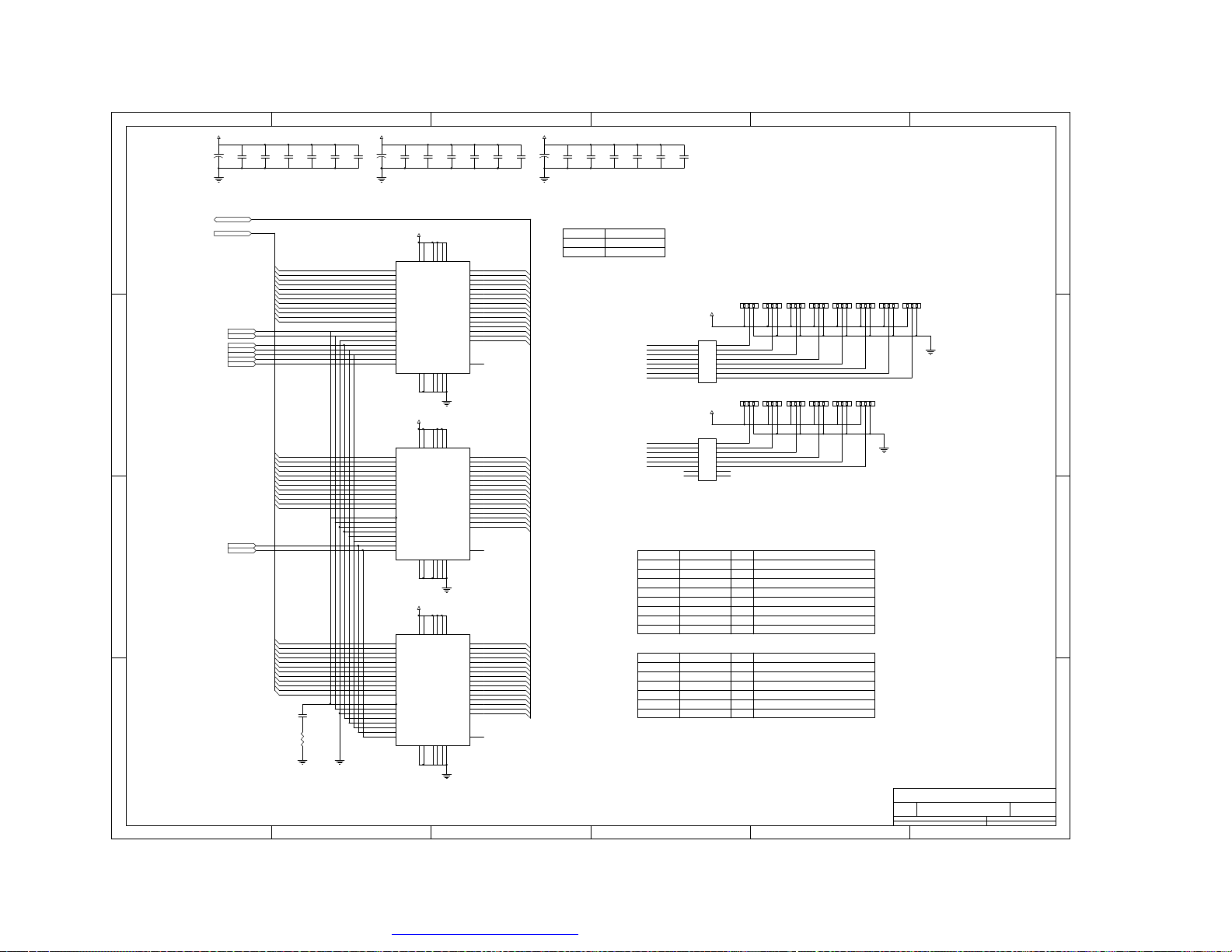
Page 46

654321
D
+3.3V
L200
C203
C204
C205
0.1uF
RST_LVDS
R200
1K-NS
R201
1K
C206
0.1uF
0.1uF
383-VCC
RO7
RO5
GO0
GND
GO1
GO2
GO6
GO7
GO3
GO4
GND
GO5
BO0
BO6
BO7
BO1
BO2
GND
BO3
BO4
BO5
LH
LV
0.1uF
C202
10uF/10V
C
B
1
2
3
4
5
6
7
8
9
10
11
12
13
14
15
16
17
18
19
20
21
22
23
24
25
26
27
28
IC200
VCC
R7/TxIN5
R5/TxIN6
G0/TxIN7
GND
G1/TxIN8
G2/TxIN9
G6/TxIN10
VCC
G7/TxIN11
G3/TxIN12
G4/TxIN13
GND
G5/TxIN14
B0/TxIN15
B6/TxIN16
R_FB
B7/TxIN17
B1/TxIN18
B2/TxIN19
GND
B3/TxIN20
B4/TxIN21
B5/TxIN22
RES/TxIN23
VCC
Hsync/TxIN24
Vsync/TxIN25
DS90C383MTD
R4/TxIN4
R3/TxIN3
R2/TxIN2
R1/TxIN1
R0/TxIN0
R6/TxIN27
LVDS-GND
TX0+
TX1+
LVDS_VCC
LVDS_GND
TX2+
CLKOUT-
CLKOUT+
TX3+
LVDS_GND
PLL_GND
PLL_VCC
PLL_GND
PWR_DWN
CLKIN
EN/TxIN26
+5V+3.3V
L201
C200
0.1uF
RO4
56
RO3
55
RO2
54
GND
53
GND
RO1
52
RO0
51
RO6
50
GND
49
TX0-
48
TX0-
47
46
TX1-
45
44
GND
43
42
TX2-
41
40
39
38
TX3-
37
GND
36
GND
35
34
GND
33
32
CLOCK
31
DE
30
GND
29
GND
L203
C208
0.1uF
C207
10uF/16V
L202
+3.3V
+3.3V
R2024.7K
R545
12
Q508
BC848
LVDS-ON
10K
RGB-OUT
1
DARED0
3
DARED1
5
DARED2
7
DARED3
C201
0.1uF
+3.3V
CN201
1
VCC
2
VCC
GND
3
GND
GND
4
GND
5
TX0-
6
TX0+
GND
7
GND
8
TX1-
9
TX1+
GND
10
GND
11
TX2-
12
TX2+
GND
13
GND
14
CLK-
15
CLK+
GND
16
GND
17
TX3-
18
TX3+
GND
19
GND
GND
20
GND
2.0*20
RP20047*4
1
DARED4
3
DARED5
5
DARED6
7
DARED7
RP20147*4
1
DAGRN0
3
DAGRN1
5
DAGRN2
7
DAGRN3DBGRN3
RP20247*4
1
3
DAGRN5
5
DAGRN6
7
DAGRN7
RP20347*4
1
DABLU0
3
DABLU1
5
DABLU2
7
DABLU3
RP20647*4
1
DABLU4
3
DABLU5
5
DABLU6
7
DABLU7
RP20747*4
1
DHS
3
DVS
5
DEN
7
DCLK
RP20847*4
RO0
2
RO1
4
RO2
6
RO3
8
RO4
2
RO5
4
RO6
6
RO7
8
GO0
2
GO1
4
GO2
6
GO3
8
GO4
2
GO5
4
GO6
6
GO7
8
BO0
2
BO1
4
BO2
6
BO3
8
BO4
2
BO5
4
BO6
6
BO7
8
LH
2
LV
4
DE
6
8
CLOCK
1
DBRED0
3
DBRED1
5
DBRED2
7
DBRED3
RP20447*4
1
DBRED4
3
DBRED5
5
DBRED6
7
DBRED7
RP20547*4
1
DBGRN0
3
DBGRN1
5
DBGRN2
7
RP20947*4
1
DBGRN4DAGRN4
3
DBGRN5
5
DBGRN6
7
DBGRN7
RP21047*4
1
DBBLU0
3
DBBLU1
5
DBBLU2
7
DBBLU3
RP21147*4
1
DBBLU4
3
DBBLU5
5
DBBLU6
7
DBBLU7
RP21247*4
CN200
1 2
3 4
LV
5 6
RO0
7 8
RO2
9 10
RO4
11 12
RO5RO6
13 14
RO7
15 16
17 18
GO2
19 20
GO4
21 22
GO5
23 24
GO7
25 26
27 28
BO2BO3
29 30
BO4
31 32
BO5
33 34
BO7
+12V +12V
35 36
DE
37 38
39 40
41 42
RE0
2
RE1
4
RE2
6
RE3
8
RE4
2
RE5
4
RE6
6
RE7
8
GE0
2
GE1
4
GE2
6
GE3
8
GE4
2
GE5
4
GE6
6
GE7
8
BE0
2
BE1
4
BE2
6
BE3
8
BE4
2
BE5
4
BE6
6
BE7
8
CLOCK
LH
RO1
RO3
GO0
GO1
GO3
GO6
BO0
BO1
BO6
CN202
30
30
29
29
28
28
27
27
26
26
25
25
24
24
23
23
22
22
21
21
20
20
19
19
18
18
17
17
16
16
15
15
14
14
13
13
12
12
11
11
10
10
9
9
8
8
7
7
6
6
5
5
4
4
3
3
2
2
1
1
04 6240 030
D
C
B
21*2
A
1 2 3 4 56
PDF 文件使用 "pdfFactory" 试用版本创建 www.fineprint.com.cn
Title
NumberRevisionSize
B
Date:10-Jun-2004Sheet of
File:C:\DOCUME~1\ADMINI~1\LOCALS~1\Temp\Rar\NEW SKY5020.DDBDrawn By:
A
Page 47

654321
D
C
B
D
C
tuner
tuner
B
A
1 2 3 4 56
PDF 文件使用 "pdfFactory" 试用版本创建 www.fineprint.com.cn
Title
NumberRevisionSize
B
Date:10-Jun-2004Sheet of
File:C:\DOCUME~1\ADMINI~1\LOCALS~1\Temp\Rar\NEW SKY5020.DDBDrawn By:
A
Page 48
D
+5V
C
B
L4
12UH
C9
22U/16V
SCL
SDA
+33V
AGC1TU2AS3SCL4SDA5NC6VCC7NC8VT9GND10IF
12 13
C10
R10
0.1uF
6.2K
C11
22U/16V
C12
100PF
R11
100
R12
100
IC1
TDF-3CT
100U/50V
C13
100PF
654321
SIF
AM
1415
R1
R13
75
C15
220uF
Q1
BC848
C16
0.01uF
R14
100
+5V
R15
10K
SYS M SW
L' SW
P/N P SW
4.7K
R16
1K
Q4
BC848
11
C14
R2
1.2K
C17
0.01uF
Q2
2SC2717
R17
56K
R38
10K
L1
1uH
R3
470
R18
33
C18
0.01uF
+5V
C1
0.01uF
C20
C19
0.01uF
0.01uF
R19
2.2K
R20
2.2K
+5V
R29
10K
R4
220C20.01uF
C21
1000pF
R21
120
D1
MA858
R22
10K
D2MA158
R23
10K
Q5
1815
C22
0.01uF
C3
22U/16V
1
2
Q3
1815
1
2
SAW1
+9V
R5
L2
15K
12U
5
4
3
SAW2
1
5
2
4
3
R30
10K
5
4
3
SAW3
R24
10K
R6
100
C4
0.1uF
R7
10K
25
26
28
Rcomp
Vi SIF227Vi,SIF2
Vi SIF11VI SIF12Vsw3GND4CAGC5Vi VIF6Vi VIF7C AGC8GND9Rtop10Itun11Vo vid12NC/VSW13NC/VSW
C26
10U 16V
R8
24K
C522P
L5
21
22Vs23
24
VAFC
Vo FM
NC/VoAM
C27
2.2U 50V
L7
3.3uH
R25
120
R26
1K
X1
L5.5
+5VE
R9 150
C6 22U
C25
C24 470N
17LF18
19
Vsw
Vvco20Vvco
TDA4472/40
IC2
RP1
C28
10K
0.01uF
+5VE
470NF
15
16
Cref
GND
NC/CBL
14
RP2
10K
R35
150
R27
150
R36
Q6
150
BC858
C7
0.1uFC8100U
L3
12UH
+5V
L8
12UH
R32
1K
R37
1K
C100
0.1uF
Q9
BC848
Q8
BC848
+5V
D
C
C101
100U
R34
TV-CVBS
75
R33
75
CVBS-SC
B
A
1 2 3 4 56
PDF 文件使用 "pdfFactory" 试用版本创建 www.fineprint.com.cn
Title
NumberRevisionSize
B
Date:10-Jun-2004Sheet of
File:C:\DOCUME~1\ADMINI~1\LOCALS~1\Temp\Rar\NEW SKY5020.DDBDrawn By:
A
Page 49
654321
D
C
B
M3415
M3415
D
C
B
A
1 2 3 4 56
PDF 文件使用 "pdfFactory" 试用版本创建 www.fineprint.com.cn
Title
NumberRevisionSize
B
Date:10-Jun-2004Sheet of
File:C:\DOCUME~1\ADMINI~1\LOCALS~1\Temp\Rar\NEW SKY5020.DDBDrawn By:
A
Page 50
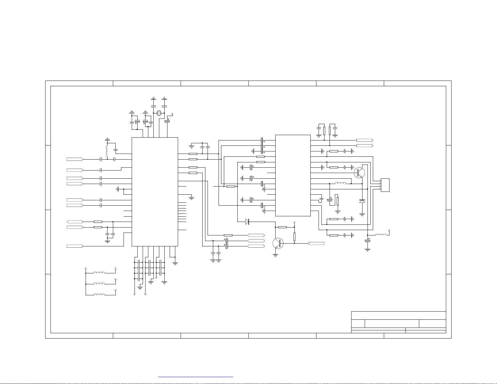
D
L301
12uH
C313
SIF
AM
C
B
A
AV-L
AV-R
SC-L
SC-R
SDA
SCL
RESETQ
82PF
C314330N
C315330N
C316330N
C317330N
C318330N
R312100
R313100
C333
100pF
RESETQ
+5V
L301
FERRITE BEAD
L303
FERRITE BEAD
L304
FERRITE BEAD
1 2 3 4 56
DVSUP
AVSUP
AHVSUP
654321
C303
22pF
C302
3.3U
C301
10U
C300
100N
34
46
ANA_IN-
ANA_IN1+
MONO_IN
SC1_IN_L
SC1_IN_R
ASG
ASG
SC2_IN_L
SC2_IN_R
STANDBYQ
ADR_SEL
I2C_DA
I2C_CL
RESETQ
DVSUP
AGNDC
VREFTOP
10
AVSUP
10uF_E
C320
56PF
51
50
C319
82PF
47
44
45
43
40
41
42
63
62
2
1
16
C334
100pF
C335
220P
C336
470P
C337
1.5nF
C348
10uF_E
54
XTAL_IN
AHVSUP
C349
470P
C350
1.5nF
C351
C304
X300
18.432MHz
100N
55
XTAL_OUT
C305
AHVSUP
C306
10U
32
CAPL_M
DACM_L
DACM_R
SC1_OUT_L
SC1_OUT_R
D_CTR_I/O_0
D_CTR_I/O_1
TESTEN
ADR_WS
ADR_CL
ADR_DA
I2S_WS
I2S_CL
I2S_DA_IN1
I2S_DA_IN2
I2S_DA_OUT
VREF127AHVSS33AHVSUP31AVSS48AVSUP49DVSS11DVSUP
C338
470P
C339
1.5nF
C340
10uF_E
22pF
C311
R30010C312
R301
47N
10
11
12
13
14
1
2
3
4
5
6
7
8
9
IC301
HP IN1
HP IN2
HP D.C
HP Standby
AMP Standby
D.C
DDL
ON TIME
IN2
PRE GND
NC
IN-VREF
IN1
POWER GND
LA4915
R318
10K
Q301
BC848
POWER GND
+5V
R319
10K
HP OUT1
HP OUT2
OUT2-
OUT2+
SW GND
SW OUT
OUT1+
OUT1-
28
27
26
25
24
23
22
SWB
21
SWE
20
19
VCC
18
17
16
15
HP-O/F
IC300
C308
C307
1000P
1000P
21
R303100
20
100
R304
R305100
29
R306100
28
61
60
53
8
9
7
4
3
6
12
5
56
TP
MSP3415G
VREF2
19
C341
2200P
R314100
C342
2200P
R3175.1K
C34322U
C34422U
C3091U/10V
C3101U/10V
C323
47U/25V
D301
4148
R307100
R308100
C32447U/25V
C327
22U/25V
C325
2.2U/10V
C328
2.2U/10V
C326
2.2U/10V
L' SW
SC-LO
SC-RO
C329
1000P
C330
2.2U/25V
47N
10
HP-R out
HP-L out
C331100NR3092.2
C332100NR3102.2
Q300
1815
L300
200uH
D300
R311
Di
2.2
C345100NR3152.2
C346100NR3162.2
C347
1000U/25V
Title
B
Date:10-Jun-2004Sheet of
File:C:\DOCUME~1\ADMINI~1\LOCALS~1\Temp\Rar\NEW SKY5020.DDBDrawn By:
NumberRevisionSize
JP300
1
2
3
4
HEADER 4
L302
FERRITE BEAD
+12V
D
C
B
A
PDF 文件使用 "pdfFactory" 试用版本创建 www.fineprint.com.cn
 Loading...