


OWNER’S GUIDE
LT3000 ATV 3000 Ib (1361 kg)
! CAUTION
12 Volt DC Electric Winch
READ AND UNDERSTAND THIS GUIDE BEFORE
INSTALLATION AND OPERATION.
Superwinch, LLC. |
|
Superwinch, Inc. |
Winch Drive |
Union Mine Road |
|
Putnam, CT 06260 |
|
Pitts Cleave |
U.S.A. |
Tavistock, Devon |
|
Tel: (860) 928-7787 |
|
PL19 OPW UK |
Fax: (860) 963-0811 |
Tel: 44 |
(0) 1822 614101 |
e-mail: info@superwinch.com |
Fax: 44 |
(0) 1822 615204 |
www.superwinch.com |
e-mail: sales@superwinch.net |
|
|
www.superwinch.com |
|
Throughout this manual, you will find notations with the following headings:
! DANGER
!WARNING
!CAUTION
Indicates an imminently hazardous situation which, if not avoided, will result in death or serious injury.
Indicates a potentially hazardous situation which, if not avoided, could result in death or serious injury.
Indicates a potentially hazardous situation which, if not avoided, may result in minor or moderate injury. This notation is also used to alert against unsafe practices.
The following symbols on the product and in the Owner's manual are used:
Read Owner's |
Always Use |
Keep clear of winch, |
Never use winch |
Never use |
Manual |
Handsaver |
wire rope and hook |
to lift or move |
winch to hold |
|
|
while operating |
people |
loads in place |
Note: Indicates additional informationin the installationand operation procedures of your winch.
Correct installationof your winch is a requirement for proper operation.
Please Note: Winch is designed primarily for intermittentapplications.This winch is not designed to be used in industrial or hoisting applicationsand Superwinch does not warrant it to be suitable for such use.
87-10994 Rev - 3/1/10
1
GENERAL SAFETY
INFORMATION
Your winch is a very powerful machine. If used unsafely or improperly, there is a possibility that property damage or personal injury could result.
The responsibility ! WARNING for safe installa-
tion and operation of the winch and prevention of personal injury and property damage ultimately rests with you, the operator. There is no substitute for the use of good judgement and caution in operating a winch.
! WARNING |
The wire rope |
|
may break before |
the winch stalls. For heavy loads, use a pulley block to reduce the load on the wire rope.
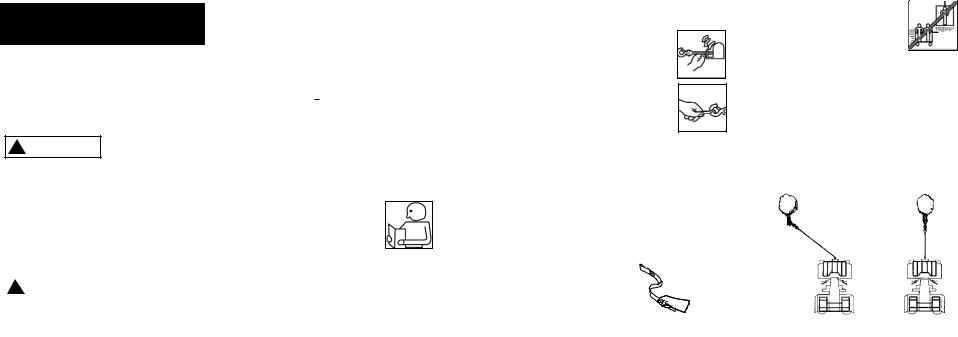
1.Maximum working load capacity is on the wire rope layer closest to the drum. DO NOT OVERLOAD. DO NOT ATTEMPT PROLONGED PULLS AT HEAVY LOADS. Overloads can damage the winch and/or the wire rope and create unsafe operating conditions. FOR LOADS OVER 1,000 POUNDS (454 kg), WE RECOMMEND THE USE OF THE OPTIONAL PULLEY BLOCK TO DOUBLE LINE THE WIRE ROPE (Figure2). This reduces the load on the winch and the strain on the wire rope by approximately 50%. Attach hook to load bearing part.
The vehicle engine should be running during winch operation. If considerable winching is performed with the engine off, the battery may be too weak to restart the engine.
Single Line
Double Line
Figure 2
2.AFTER READING AND UNDERSTANDING THIS MANUAL, LEARN TO USE YOUR WINCH.
After installingthe winch, practice using it so you will be familiar with it when the need arises.
3.DO NOT“move” your vehicle to assist the winch in pulling the load. The combination of the winch and vehicle pulling together could overload the wire rope and the winch.
4.ALWAYS STAND CLEAR OF WIRE ROPE, HOOK AND WINCH. IN THE UNLIKELY EVENT OF ANY COMPONENT FAILURE IT‘S BEST TO BE OUT OF HARM‘S WAY.
5.INSPECT WIRE ROPE AND EQUIPMENT FREQUENTLY. A FRAYED
WIRE ROPE WITH BROKEN STRANDS SHOULD BE REPLACED IMMEDIATELY.
Always replace wire rope with the manufacturer‘s identical replacement part (see Replacement Parts List). Periodically check the winch installation to ensure that all bolts are tight.
6.USE HEAVY LEATHER GLOVES when handling wire rope. DO NOT LET WIRE ROPE SLIDE THROUGH YOUR HANDS.
7.NEVER WINCH WITH LESS THAN 5 TURNS of wire rope AROUND THE WINCH DRUM since the wire rope end fastener may NOT withstand full load.
8.KEEP CLEAR OF WINCH, TAUT WIRE ROPE AND HOOK WHEN OPERATING WINCH.
Never put your finger through the hook. If your finger should become trapped in the hook, you could lose your finger. ALWAYS USE THE
HANDSAVER when guiding the wire rope in or out (See Figure 3) .
Figure 3
9.NEVER HOOK THE WIRE ROPE BACK ONTO ITSELF because you could damage the wire rope. Use a nylon sling (Figure 4).
Wrong |
Right |
Figure 4
10 .It is a good idea to lay a heavy blanket or jacket over the wire rope near the hook end when pulling heavy loads (Figure 5). If a wire rope failure should occur, the cloth will act as a damper and help prevent the rope from whipping.
Figure 5
11.NEVER USE YOUR WINCH FOR LIFTING OR MOVING PEOPLE.
12 .Your winch is not intended for overhead hoisting operations.
13 .AVOID CONTINUOUS PULLS FROM EXTREME ANGLES as this will cause the wire rope to pile up on one end of the drum (Figure 6). This can jam the wire rope in the winch, causing damage to the rope or the winch.
Figure 6
Wrong Right
14.NEVER OBSCURE THE WARNING INSTRUCTION LABELS.
15 .Always operate winch with an unobstructed view of the winching operation.
16.Equipment such as tackle, hooks, pulley blocks, straps, etc. should be sized to the winching task and should be periodically inspected for damage that could reduce their strength.
17 .NEVER RELEASE FREESPOOL CLUTCH WHEN THERE IS A LOAD ON THE WINCH.
18.NEVER WORK ON OR AROUND
THE WINCH DRUM WHEN
WINCH IS UNDER LOAD.
19.DO NOT OPERATE WINCH WHEN UNDER THE INFLUENCE OF DRUGS, ALCOHOL OR MEDICATION.
2 |
3 |

20.ALWAYS DISCONNECT WINCH POWER LEADS TO BATTERY BEFORE WORKING IN OR AROUND THE WINCH DRUM so that the winch cannot be turned on accidentally.
21.When moving a load, slowly take up the wire rope slack until it becomes taut. Stop, recheck all winching connections. Be sure the hook is properly seated. If a nylon sling is used, check the attachment to the load.
22.When using your winch to move a load, place the vehicle transmission in neutral, set vehicle brake, and chock all wheels.
23.DO NOT USE THE WINCH TO HOLD LOADS IN PLACE.
Use other means of securing loads such as tie down straps.
24.USE ONLY FACTORY APPROVED SWITCHES, REMOTE CONTROLS AND ACCESSORIES. Use of nonfactory approved components may cause injury or property damage and could void your warranty.
25.DO NOT MACHINE OR WELD ANY PART OF THE WINCH. Such alterations may weaken the structural integrity of the winch and could void your warranty.
26.DO NOT CONNECT WINCH TO EITHER 110V AC HOUSE CURRENT OR 220V MAINS AS WINCH BURNOUT OR FATAL SHOCK MAY OCCUR.
27.Never allow shock loads to be applied to winch or wire rope.
28.Use caution when pulling or lowering a load up and down a ramp or incline. Keep people, pets and property clear of the path of the load.
4
INSTALLATION
Correct installation of your winch is required for proper operation.
Step (1)
Disconnect the vehicle battery leads from the battery.
Step (2)
Secure winch (Figure) to mounting plate or structural support using the M8 x 1.25 x 30mm mount bolts, flat washers, and lock washers provided. Typical mount is to a flat secure surface capable of handling the required loads.
Step (3)
Remove bottom roller from the roller fairlead. Turn the freespool knob to disengage and pull a few inches of wire rope from the drum. Pass the wire end under the remaining roller, and then replace the bottom roller. Next secure the roller fairlead
( Figure 7) to the mounting roller plate or structural support using the M8 x 1.25 x 20mm bolts, flat washers, and lock washers provided.
Do not substitute ! WARNING any strength grade
weaker than ISO grade 8.8
Be sure that both
! WARNING the mounting plate and winch hardware have been properly tightened.
|
|
No part of the vehicle |
|
! CAUTION |
|
|
|
(skid plates, wiring, |
|
|
|
auxiliary lights, tires, ect.) should |
||
impede the operation of your Superwinch®. When mounting, check all vehicle and winch parts for free operation. Be sure that the winch mounting location does not significantly reduce ground clearance.
! WARNING This winch MUST be mounted with the
wire rope in the underwind direction. Improper mounting could damage your winch and void your warranty.
Use the supplied hardware and brackets to mount the handlebar switch. Mount the solenoid close to the battery, in the storage box, under the seat or frame.
|
|
The location |
|
|
|
! |
WARNING |
|
|
||
|
|
of the switch |
|
|
|
|
|
|
|
||
MUST not interfere with safe |
|
|
|||
operation of the vehicle. |
|
|
|||
Wiring MUST NOT come in |
Figure 7 |
||||
contact with any moving |
|||||
parts or sharp edges, such |
|
|
|||
as engine, suspension, brakes, |
|
|
|||
exhaust, or steering. |
|
|
|||
Route the Red wire from |
|
|
|||
the handlebar switch to |
|
|
|||
the ignition switch and |
|
|
|||
connect to the wire |
|
|
|||
that is powered |
|
|
|||
when ignition |
|
|
|||
is in the ON |
|
|
|||
position ONLY. |
|
|
|||
Route the two |
|
|
|||
wires from the |
|
|
|||
solenoid to the motor Figure 8. Route |
winch in Cable Out momentarily to |
||||
the two wires from the solenoid to |
|
check drum rotation direction. If the |
|||
the battery. Attach the circuit breaker |
drum rotates in the wrong direc- |
||||
to the end of the red wire. Wrap the |
tion, recheck your wiring. |
||||
circuit breaker with electrical tape to |
FREESPOOL OPERATION |
||||
prevent accidental short circuits. |
|
||||
Apply several layers of electrical tape |
Turn the clutch knob to the, Disen- |
||||
where wiring may come into contact |
gaged “Free” position as shown in |
||||
with sharp metal parts of the vehicle |
Figure 10. If there is a load on the |
||||
to prevent insulation abrasion or cut- |
wire rope, the clutch knob may not |
||||
ting. |
|
pull out easily. DO NOT FORCE THE |
|||
Attach the short circuit breaker wire to |
CLUTCH KNOB. Release tension on |
||||
the clutch by jogging out some of |
|||||
the battery positive terminal and reat- |
|||||
the wire rope. |
|||||
tach the terminal to the battery. Con- |
|||||
Release the clutch and pull out the |
|||||
nect the remaining black solenoid wire |
|||||
wire rope and secure to anchor or |
|||||
to the battery negative terminal and |
|||||
load. Check that there are at least |
|||||
connect the terminal to the battery. |
|||||
five (5) turns of wire rope left on |
|||||
|
|
|
|
||
STEP (4) |
|
the drum. Re-engage the drum by |
|||
Turn the clutch knob to, Disengaged |
returning the clutch knob to the, |
||||
“Free” position as shown in Figure 10. |
“Engaged” position. (See Figure 10). |
||||
Pull several feet of wire rope off the drum. Return the clutch knob back to the, “Engaged” position. Activate the
5
4

Figure 8 |
|
|
|
Figure 6 |
|
|
21 |
|
|
|
|
|
|
Red |
|
|
|
Y llow – 6 ga. |
|
ATV MASTER WIRINGS |
|
||
|
ATV main |
|
|
|
switch |
|
|
|
Fuse |
Black |
Blackk |
|
Green |
||
Brown/Blue |
Red |
Green |
|
|
|
BlueBlack |
|
|
|
|
|
|
Red |
|
|
|
ATV wiring |
|
|
optional remote |
connection |
|
Green |
|
|
||
control |
|
|
Black |
|
optional |
|
|
|
|
|
|
WINCH
12
BlueBlack– 6 ga.- 6 ga.
|
BATTERY |
|
Black – 6 ga. |
|
CIRCUIT |
SOLENOID |
BREAKER |
"+" |
|
|
to solenoid |
|
Red – 6 ga. |
|
to circuit breaker |
9
Ø.86”
Ø 21.8mm
REMOTE SOCKET MOUNTING
1. Detemine the mounting location for the remote socket.
2.Drill three holes using the included dimensions as a guide.
3.Once the remote socket is mounted, route the jacketed green and black leads back to where the solenoid is mounted. Splice the red lead to a key controlled electrical wire on the ATV.
1.95”
49.5mm
.18” 4.6mm
.98”
24.8mm
Disengaged
(Freespool)
|
|
|
Clutch must be fully |
|
! |
CAUTION |
|
|
engaged before |
||
|
|
|
|
winching. Never engage clutch knob |
|||
while drum is turning. |
|||
|
|
Figure 10 |
|
Engaged
6
|
|
|
If the winch motor |
|
! |
CAUTION |
|
|
stalls, do not |
||
|
|
|
|
|
|
|
|
continue to apply power. |
|||
INTERMITTENT DUTY
An electric winch is like any other motor driven power tool such as an electric drill or saw. The electric motorshould not be allowed to become excessively hot. Normal precautions will extend the life of your motor. Keep the durations of pulls as short as possible.
If the end of the motor becomes uncomfortably hot to touch, stop winching and allow the motor to cool down.
For further information and complete warranty, visit our website. www.superwinch.com
REPLACEMENT PARTS LIST
|
1 |
5 |
8 |
7 |
|
|
|
|
|
|
6 |
2 |
|
4 |
|
|
|
|
3 |
|
|
9 |
|
Reference No. |
Description |
Part Number |
1 |
Wire Rope Assy. |
1511F |
2 |
Motor Assy. |
87-12890 |
3 |
Drum Assy. |
87-12891 |
4 |
Gearbox Assy. |
87-12892 |
5 |
Solenoid Assy. |
87-12893 |
6 |
Handlebar Rocker Switch |
87-12894 |
7 |
Hand Held Remote |
87-12895 |
8 |
Circuit Breaker Assy. |
87-22873-16 |
9 |
Clevis Hook Assy. |
87-42615 |
|
|
7 |
 Loading...