

Page 1

Oxygen Sensor
Operations Manual
TM
SuperOX
U.S. Patent No. 5,635,044
Super Systems Inc.
7205 Edington Drive
Cincinnati, OH 45249
513-772-0060
800-666-4330
Fax: 513-772-9466
www.supersystems.com
Page 2

Table of Contents
Introduction ..................................................................................................................................... 3
Specifications .................................................................................................................................. 3
Characteristics ................................................................................................................................ 3
Operating Theory ............................................................................................................................ 4
Installation ...................................................................................................................................... 5
Troubleshooting .............................................................................................................................. 7
Glass Tank/Glass Furnace Installation ........................................................................................... 9
Warranty.........................................................................................................................................12
Notes ..............................................................................................................................................13
Revision History .............................................................................................................................14
Super Systems Inc. Page 2 of 14 SuperOXTM Operations Manual
Page 3
Introduction
-20
F
• Overall length: 26.5” (67.31 cm), 35.5”
NPT female
Sheath diameter: 1.00" (25.4 mm)
Thank you for selecting the Super Systems Inc. (SSi) SuperOXTM Sensor for your combustion
control application.
TM
SuperOX
represents "state of the art" in oxygen sensor technology. It has been designed for
use in combustion control systems for glass, power, steel reheat, chemical process and
incineration applications.
TM
SuperOX
, with its patented measuring electrode construction, is the product of a team of
design and application engineers, each with over twenty years of atmosphere control
experience. The SSi engineering team has long recognized that the sensor is the most critical
component in a control system and has traditionally been the weakest link. Now, reliability,
TM
repeatability and accuracy are assured with the use of SSi’s SuperOX
high temperature, in situ
sensor in your system.
Specifications
• Useful O
• Temperature range: 1200
• Stability: within +/- 1 mvdc
• Impedance: less than 5 kohms @ 1700
• Useful output: -50 to 1250 mvdc
Range: 10
2
to 100%
o
F to 2900
o
o
F
(90.17 cm), and 44.5” (113.03 cm)
• Weight: 3.0 lbs.
• Insertion to 18” (45.72 cm), 27” (68.58 cm),
and 36” (91.44 cm)
• Mounting: into 1" (25.4 mm)
•
Characteristics
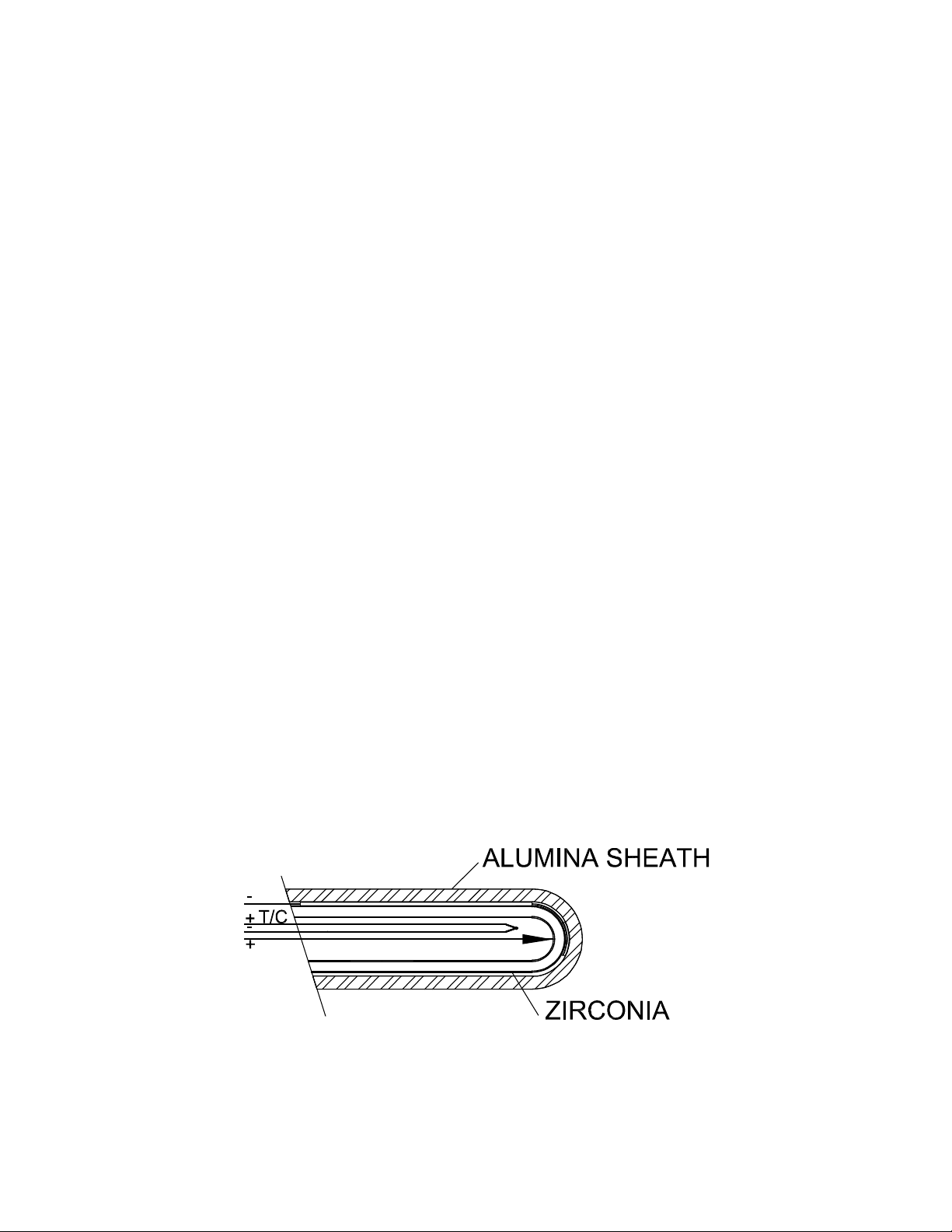
The typical zirconia oxygen sensor consists of a closed end tube with the sensing portion at the
tip. The tube operates on the principle of yttria-stabilized zirconia. Figure 1 illustrates the
SuperOX
TM
Sensor design with details omitted for clarity. The tip of the tube is spring loaded into
contact with the outer, negative platinum electrode, which is in contact with the ceramic sheath.
The inner, positive electrode is spring loaded into contact with the inner zirconia surface. A
thermocouple is positioned close to the inner electrode surface and reference air bathes the
sensing surface.
Super Systems Inc. Page 3 of 14 SuperOXTM Operations Manual
Figure 1
Page 4
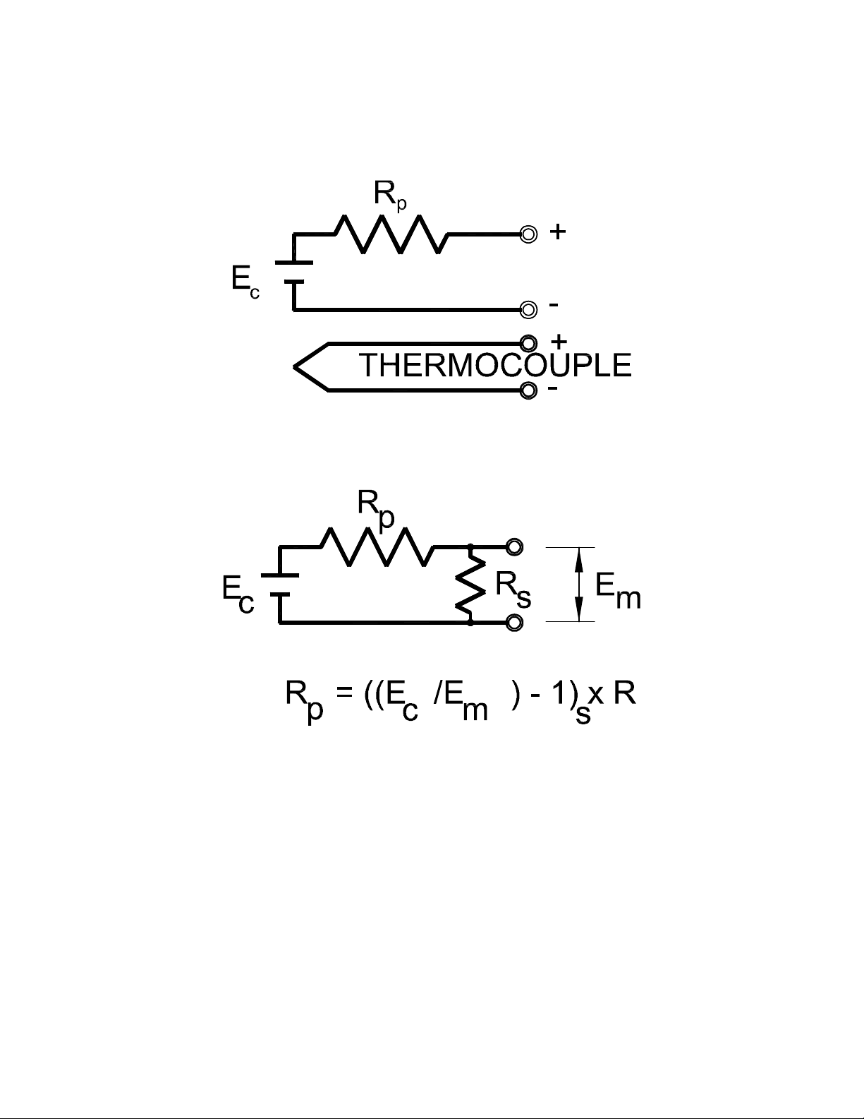
To the instrument technician, the sensor looks like a battery (see Figure 2). It displays a voltage,
EC, from which the carbon potential can be calculated. The probe thermocouple is shown next
to the sensing electrode.
Figure 2
The value of the internal resistance can be measured, as shown in Figure 3, by connecting a
shunt resistor across the sensor terminals, measuring the resultant voltage, Em, and carrying
out the simple calculation shown.
Figure 3
Operating Theory
Oxygen concentration of a conventional combustion atmosphere is measured by an in situ
zirconia sensor, which responds to oxygen according to the Nernst equation shown here.
Because the equation is logarithmic (to the base 10), the coefficient 0.0496TR is the number of
millivolts accompanying a tenfold change in concentration:
Ec= -0.02756TR log (PR /PF) millivolts
where TR is the temp in degrees Rankine and PF and PR are the % oxygen (O2) in the furnace
and the reference gas.
Super Systems Inc. Page 4 of 14 SuperOXTM Operations Manual
Page 5

Installation
If your new sensor is to be installed in an existing entry port, be advised that the sensor is 100%
interchangeable with your current sensor.
For new installations in furnaces, an
entry fitting
must be provided at the furnace wall to permit
the sensor to extend into the furnace chamber. The furnace is prepared by drilling (ideally) a 3”
(76.2 mm) diameter hole through the wall and the insulation. A 1" (25.4 mm) coupling may then
be welded to the wall to provide the gas-tight entry. As the SuperOX
TM
has a 1" (25.4 mm) NPT
hub; use of conventional 1" (25.4 mm) fittings allows for appropriate installation. A combination
of 1" (25.4 mm) nipples and couplings allows for appropriate insertion depth.
Your SuperOXTM Sensor has been shipped with TeflonTM pipe tape applied to the gland, so you
may insert it directly into the furnace. When installing in a hot furnace, insert the first two
inches (50.8 mm) directly, then at a rate of no faster than 4" (101.6 mm) per 5 minutes
in order
to avoid thermal shock fracture. Support the cover end of the sensor during installation.
The sensor requires a reference air supply. In addition, the SuperOX
TM
Sensor has been
designed with an optional cooling port that may require an additional air supply. SSi provides a
custom system, P/N 13017, that supplies both requirements.
It is imperative to emphasize that the reference air must be
dry, clean, and oil free.
Any
combustibles in the reference air will cause the sensor to read high in oxygen. Avoid the use of
lubricated compressed plant air. The air connection at the sensor should be made of silicone
rubber tubing to avoid problems related to the high temperatures normally encountered at the
sensor connection block. Reference air flow should be in the range of 0.2 to 2 CFH at no more
than 2 psi. Cooling air flow should be in the range of 1 to 10 CFH at no more than 2 psi.
Figure 4 and Figure 5 show installations in furnaces and glass tank regenerators.
These views show the installation of SuperOXTM probes in the walls of two different furnaces
furnace, utilizing a silicon protection tube which requires a 1 ½” (38.1 mm) coupling (or half
coupling) entry. This arrangement is typically used for extremely high temperature applications.
The wall is typically 13 ½” (342.9 mm) thick. Correct location of the sensor in the protection tube
may be accomplished by inserting a 1” (25.4 mm) coupling and appropriate length 1” (25.4 mm)
nipple between the sensor and the protection tube. There are three lengths of protection tubes
for use with sensors of 18” (45.72 cm), 27” (68.58 cm) and 36” (91.44 cm) lengths. When using
the unprotected sensor
NOTE: A protection tube is not required for use of the SuperOX
, a 1” (25.4 mm) coupling (or half coupling) can be used for direct entry.
TM
Sensor.
Super Systems Inc. Page 5 of 14 SuperOXTM Operations Manual
Page 6

Protection Tube
1 1/2” (38.1 mm) Coupling,
Gas Tight Weld
Hot Face
Furnace Wall
SuperOX
TM
1 3/4” (44.45 mm) Diameter Hole
Protection Tube
1 1/2” (38.1 mm) Coupling,
Gas Tight Weld
Hot Face
Furnace Wall
1 3/4” (44.45 mm) Diameter Hole
SuperOX
TM
1” to 2” (25.4 mm to 50.8 mm) Recess
Standard Installation
Figure 4
Glass Tank Installation
Figure 5
The standard SuperOXTM, Ver. 2.0, is provided with a 5 foot long high-temperature cable, as
illustrated in Figure 6, so that a plug may be mounted for interconnection with the customer’s
measurement and control instrumentation. Alternatively (and preferably), the customer may
feed his instrument interconnection cable through the cord connector, and make connections
directly to the internal connector.
Super Systems Inc. Page 6 of 14 SuperOXTM Operations Manual
Page 7

Figure 6
Wire designation:
R
e
fe
ren
c
e
Air
C
ooling
Air
C
able
E
nt
r
y
White (Sensor +)
Black (Sensor -)
Green (Thermocouple +)
Red (Thermocouple - )
Troubleshooting
When trouble arises with an oxygen control system, it is important to establish where the
problem is located: the sensor, signal transmission lines, the control instrument, or the
combustion chamber itself. Several simple tests can help to isolate the problem quickly. It is
most important to first understand the nature of the fault. Aside from erratic behavior like
cycling, or failure to stabilize at the setpoint, the most common symptom is non-conformity of
the work pieces to quality assurance specifications.
To evaluate most faults, the recommended tools are:
1. A 3 1/2-digit millivoltmeter with at least 10 MΩ input impedance and 0 to 1999 mV range;
2. A temperature calibrator; and
3. A simulator to output 0 to 200 millivolts at less than 50 MΩ output impedance.
Sensor troubleshooting: In order to establish the source of problems in your installation, first
avoid removing the SuperOXTMSensor from the furnace.
questions must be answered while your sensor is at temperature and is exposed to a normal
atmosphere under
1. Are the connections from the T/C extension wire and sensor cable clean and firmly
attached at the correct sensor and control instrument terminals? Note that the shield
wire in the sensor cable should be connected to ground at the control instrument end
only!
2. Is the sensor impedance less than 50 KΩ at temperatures above 1550
test shown in Figure 3 using a shunt resistor of about 100 KΩ. Measure the voltage EC
before shunting, then EM with the shunt in place. Calculate RP. If it exceeds 50 KΩ,
proceed to step 6 below.
3. How quickly does the sensor react to a change in O
millivolts with the controller or the digital meter. Short the sensor for 5 seconds,
remove the short and measure the time required to return to within 1% of the original
reading. If it exceeds 60 seconds, proceed to step 6, below.
manual control:
All of the following meaningful
°
F? Conduct the
concentration? Read the sensor
2
Super Systems Inc. Page 7 of 14 SuperOXTM Operations Manual
Page 8

4. Is there a leak in the zirconia substrate? To test this property, turn off the reference air
for one minute. Measure the sensor mV as indicated by the controller or a digital
voltmeter. Turn the air back on and measure the mV again. If there is a difference
greater than 5 mV, replace the sensor.
5. Should it be necessary to remove your SuperOX
carefully.
UNDER NO CIRCUMSTANCES should it be removed faster than 4" (101.6 mm)
TM
Sensor from a hot furnace, do so
per 5 minutes.
6. If your atmosphere control problem cannot be resolved, our technical support staff is
available Monday through Friday, 7:00 a.m. to 6:00 p.m. Eastern Standard Time. You may
call us at (800) 666-4330.
Super Systems Inc. Page 8 of 14 SuperOXTM Operations Manual
Page 9

Glass Tank/Glass Furnace Installation
Figure 7 shows a diagram of a typical installation of a SuperOX
furnace.
TM
Sensor into a glass tank/glass
Figure 7
Safety Guidelines
WARNING: You must follow operational safety guidelines when drilling and installing a sensor
in an operating glass furnace. It may be possible to use existing furnace openings. When
repairing a furnace, or planning for new construction, you should consider drilling the holes for
oxygen sensors.
The SuperOX
TM
Sensor contains a significant number of ceramic parts. It is therefore subject to
thermal shock. The sensor must be installed in an area that provides an adequate, turbulent,
and consistent gas stream representative of the atmosphere in the process. The sensor must
be located so that the “hot” end can measure the oxygen level of the flue gas, at a temperature
Super Systems Inc. Page 9 of 14 SuperOXTM Operations Manual
Page 10

greater than 1200°F (650°C), but less than 3000°F (1650°C) in a slightly positive pressure
situation to prevent air in-leakage.
The sensor cannot be exposed in an area with excessive turbulence or high gas velocity,
especially when there is particulate in the atmosphere. In order to comply with these
requirements, SSI recommends that, for glass tanks with regenerative heating, the sensor be
installed vertically in the center of the regenerator crown or horizontally on the regenerator
“target” wall. Please note that target wall life will be significantly less when compared with a
vertical, crown installation.
For glass tanks with recuperative heating, SSI recommends installation in a vertical position in
the flue gas collector, behind the branch off, but in front of the gate valve. Please remember
the temperature constraints when looking for this location.
You must drill 2 ¾ to 3 inch (19.05 to 76.2 mm) holes through the refractory brick. This will allow
easy installation and removal of the SuperOX
TM
Sensor.
Vertical installation
Sensor should be recessed 1 to 2 inches (25.4 to 50.8 mm) into the refractory away from furnace
atmosphere. When installing the probe, it is best to insure this length of insertion. From the hot
face, one will recess the sensor until the readings begin to change. Once a change has been
observed, lower the sensor approximately ½ inch (12.7 mm) and secure the sensor in place.
Horizontal Installation
SSI recommends that the “hot” end of the sensor extend approximately 3 to 5 ½ inches (76.2 to
139.7 mm) beyond the hot face of the refractory. If there is an excessive amount of batch carryover, or if the gas stream has a very high velocity, it is recommended that the sensor be
recessed. Batch carry-over and high velocity gas will erode the sensor and significantly reduce
life.
Sensor Preparation before installation
When using the SSI oxygen mounting assembly, place the sensor at the maximum height
possible and lower it toward the furnace 2 to 4 inches (50.8 to 101.6 mm) every five minutes. If
you do not have an SSI Mounting Assembly, note that approximately 2 hours before installing
the sensor, you should lay the sensor on top of the regenerator (for pre-warming), taking care
to protect the sensor head and wiring assembly.
Sensor installation (insertion) rate
WARNING: You must follow operational safety guidelines when drilling, and installing a sensor
in an operating glass furnace. It may be possible to use existing furnace openings. When
repairing a furnace, or planning for new construction, you should consider drilling the holes for
oxygen sensors.
Insertion of the sensor should be no greater than 4 inches (101.6 mm) every 5 minutes.
Super Systems Inc. Page 10 of 14 SuperOXTM Operations Manual
Page 11

Installation Hints:
The sensor will need to be supported while being installed. The installation process will take 1
to 4 hours depending upon sensor length and rate of insertion. When the sensor is in its final
position, it is recommended that the opening be covered or filled with fiber blanket around the
protection tube.
NOTE: The sensor is warranted against workmanship defects, but not against damage caused
by installing the sensor incorrectly.
1. SuperOx
TM
- Maintenance
It is important to check the sensor’s position every one to two months. If the fiber placed
around the protection tube and the bored hole has shrunk, add fiber into the area between the
protection tube and the bored hole. Use wooden sticks or dowels. Touching the HOT ceramic
tube with a metal screw driver is
NOT recommended.
The sensor head should be observed for any excessive temperature. The internal workings of
the sensor head will ideally be exposed to temperatures no greater than 150 to 200°F (65 to
93°C).
During troubleshooting, it may be necessary to read the sensor millivolts from the sensor. If
you are asked to supply this information, please remove the electrical connection from the head
of the sensor and, using a digital voltmeter, measure the sensor millivolts by touching pins “1”
and “2,” and then observing the number reading. The number should be between 30 and 125
millivolts during a firing cycle. Check the reading against a millivolt vs temperature Oxygen
Chart. You can check the temperature by measuring the millivolts across pins “3” and “4”.
These values can be correlated using a “B-Type” thermocouple chart.
2. Reference Air System - Installation
The reference air system should be installed in an area protected from excessive heat and dust.
It is recommended that it be installed on a column or wall, at a height easily accessible for
maintenance of the air pump. The system should be installed with respect to local electrical
regulations. The reference airline needs to be run from the reference air system to the head of
the sensor. The line can be run using ¼ inch (6.35 mm) tubing (stainless or copper). Terminate
the tubing approximately 6 inches (152.4 mm) from the sensor head and finish the connection
with flexible tubing included in the sensor carton.
3. Reference Air System - Maintenance
The reference air system requires little maintenance. Changing the filter (dependent on the
dust level) 4 - 6 times per year ensures that the sensor receives a quality source of reference
air for proper function. The amount of reference air supplied to the sensor should be
maintained at 0.5 – 1.5 SCFH. The reference air pump needs to be checked periodically to
ensure proper operation.
Super Systems Inc. Page 11 of 14 SuperOXTM Operations Manual
Page 12

Warranty
• Super Systems Inc. (SSi), as manufacturer of the SuperOX
TM
Sensor, warrants it to be
free from defects in material and workmanship for a period of twelve (12) months under
normal use and service. SSi’s obligation under this warranty is limited to repairing or
replacing, at its option, the sensor described herein, should failure occur within the
warranty period. The warranty period shall commence on installation of the sensor. If
premature failure occurs, the sensor must be returned in the complete, original
packaging to SSi. Upon receipt, SSi will conduct an examination as to the cause of
failure, at which time appropriate action will be taken. See more information on
arranging for shipment of the sensor below.
• There are no warranties, expressed or implied, by the distributors or representatives for
the SuperOX
TM
Sensor, except the expressed warranty against defects described above.
There will be no applicable warranty in the event of breakage resulting from thermal or
mechanical shock. Additionally there will be no applicable warranty for a sensor that has
been subjected to misuse or negligence, or was damaged in an accident. SSi shall in no
way be liable for special or consequential damages related to the use of this sensor.
• In the case of failure or malfunction, the user must call SSi at (800) 666-4330 to arrange
for shipment of the SuperOX
TM
Sensor to SSi. As part of arranging shipment, SSi will
issue a Return Materials Authorization (RMA) number. The product must be returned in
the original packaging. It is also recommended that the user fill out the Warranty Claim
Report that is sent with the new SuperOX
TM
Sensor.
Super Systems Inc. Page 12 of 14 SuperOXTM Operations Manual
Page 13

Notes
We suggest that you use this space to keep a record of installation date, test data and
experiences with your
SuperOX
TM
Sensor.
Super Systems Inc. Page 13 of 14 SuperOXTM Operations Manual
Page 14

Rev.
Description
Date
MCO #
-
Initial Release
03/21/2001
N/A
A
Added Revision History
07/11/2001
N/A
B
Revised Fig 5 Drawing, changed Step 8 to read
Step 6
02/19/2002
2024
C
Changed “eight inches” to “two inches” Page 2
Installation Instructions
06/04/2003
2029
D
Changed company address
05/15/2005
N/A
E
Corrected air flow parameters under Installation
06/23/2011
2082
F
Changed manual to new format; implemented
05/22/2013
2123
Revision History
updated artwork to increase clarity; added Glass
Tank/Glass Furnace Installation; revised
contents as needed to match product
parameters.
Super Systems Inc. Page 14 of 14 SuperOXTM Operations Manual
 Loading...