


SINGLE-LOOP PROGRAMMABLE TEMPERATURE CONTROLLER
SERIES 9130
OPERATIONS MANUAL
Super Systems Inc.
7205 Edington Drive Cincinnati, OH 45249 513-772-0060 800-666-4330
Fax: 513-772-9466 www.supersystems.com
Table of Contents |
|
INSTALLATION SAFETY REQUIREMENTS------------------------------------------------------------------------------------------------ |
4 |
CHAPTER 1 - OVERVIEW ------------------------------------------------------------------------------------------------------------------------ |
7 |
MOUNTING------------------------------------------------------------------------------------------------------------------------------------------- |
8 |
DIMENSIONAL DRAWINGS ------------------------------------------------------------------------------------------------------------------------ |
9 |
12” OPERATOR INTERFACE CUTOUT DIMENSIONS ------------------------------------------------------------------------------------------ |
10 |
WIRING ---------------------------------------------------------------------------------------------------------------------------------------------- |
11 |
ELECTRICAL INSTALLATION --------------------------------------------------------------------------------------------------------------------- |
11 |
PIN OUT--------------------------------------------------------------------------------------------------------------------------------------------- |
12 |
ANCILLARY ITEMS --------------------------------------------------------------------------------------------------------------------------------- |
12 |
SETUP ----------------------------------------------------------------------------------------------------------------------------------------------- |
13 |
ADDITIONAL FEATURES -------------------------------------------------------------------------------------------------------------------------- |
13 |
ETHERNET CONNECTIONS----------------------------------------------------------------------------------------------------------------------- |
13 |
INSTRUMENT START-UP ------------------------------------------------------------------------------------------------------------------------- |
14 |
FLASH CARD & FLASH CARD READER-------------------------------------------------------------------------------------------------------- |
14 |
OPERATOR INTERFACE SCREEN SAVER------------------------------------------------------------------------------------------------------- |
14 |
DEFAULT STATUS SCREEN ---------------------------------------------------------------------------------------------------------------------- |
14 |
Display------------------------------------------------------------------------------------------------------------------------------------------ |
14 |
MENU------------------------------------------------------------------------------------------------------------------------------------------------ |
15 |
CHART ----------------------------------------------------------------------------------------------------------------------------------------------- |
15 |
CHART SUB MENU -------------------------------------------------------------------------------------------------------------------------------- |
16 |
RECIPE ---------------------------------------------------------------------------------------------------------------------------------------------- |
17 |
LOOPS ----------------------------------------------------------------------------------------------------------------------------------------------- |
18 |
ACK (ALARM ACKNOWLEDGE) ------------------------------------------------------------------------------------------------------------------ |
19 |
DATA LOGGING USING FLASH CARD ----------------------------------------------------------------------------------------------------------- |
19 |
CHAPTER 2 - CONFIGURATION ------------------------------------------------------------------------------------------------------------- |
20 |
MENU (CONFIGURATION) ------------------------------------------------------------------------------------------------------------------------ |
20 |
Logs --------------------------------------------------------------------------------------------------------------------------------------------- |
21 |
Slave Communications Status -------------------------------------------------------------------------------------------------------- |
22 |
Load TC/Auxiliary Analog Input------------------------------------------------------------------------------------------------------- |
22 |
Manual Event Control -------------------------------------------------------------------------------------------------------------------- |
22 |
Shutdown-------------------------------------------------------------------------------------------------------------------------------------- |
23 |
PID Loop Setup------------------------------------------------------------------------------------------------------------------------------ |
23 |
Recipe Edit------------------------------------------------------------------------------------------------------------------------------------ |
25 |
Load T/C Configuration ------------------------------------------------------------------------------------------------------------------ |
26 |
Trend Chart Edit ---------------------------------------------------------------------------------------------------------------------------- |
26 |
Communications Setup ------------------------------------------------------------------------------------------------------------------ |
28 |
Slave Instrument Setup------------------------------------------------------------------------------------------------------------------ |
30 |
Zone Assignments ---------------------------------------------------------------------------------------------------------------------------- |
32 |
Furnace Setup------------------------------------------------------------------------------------------------------------------------------- |
33 |
Default Wait Limits ------------------------------------------------------------------------------------------------------------------------ |
35 |
Alarm Setup ---------------------------------------------------------------------------------------------------------------------------------- |
35 |
Relay Assignments ------------------------------------------------------------------------------------------------------------------------ |
37 |
Analog Input Setup ------------------------------------------------------------------------------------------------------------------------ |
38 |
Analog Output Setup ---------------------------------------------------------------------------------------------------------------------- |
40 |
Alarm Polarity ------------------------------------------------------------------------------------------------------------------------------- |
41 |
Event Hold/Reset--------------------------------------------------------------------------------------------------------------------------- |
41 |
Security ---------------------------------------------------------------------------------------------------------------------------------------- |
42 |
Curve Entry ----------------------------------------------------------------------------------------------------------------------------------- |
43 |
Series 9130 Operations Manual Rev - |
1 |
Alternate PID Setup ----------------------------------------------------------------------------------------------------------------------- |
44 |
Aux Analog Input Setup ------------------------------------------------------------------------------------------------------------------ |
45 |
Equipment needed------------------------------------------------------------------------------------------------------------------------- |
45 |
Calibration ------------------------------------------------------------------------------------------------------------------------------------ |
47 |
Configuration -------------------------------------------------------------------------------------------------------------------------------- |
49 |
A/I Module Offset Correction ---------------------------------------------------------------------------------------------------------- |
53 |
PV Switching --------------------------------------------------------------------------------------------------------------------------------- |
53 |
Aux Setpoint Configuration------------------------------------------------------------------------------------------------------------- |
53 |
T/C Correction Curves ----------------------------------------------------------------------------------------------------------------------- |
54 |
Generic Instruments ---------------------------------------------------------------------------------------------------------------------- |
54 |
Tuning Assistant---------------------------------------------------------------------------------------------------------------------------- |
55 |
Timer Setup ---------------------------------------------------------------------------------------------------------------------------------- |
56 |
Instrument Calculation ------------------------------------------------------------------------------------------------------------------ |
57 |
CHAPTER 3 – CONFIGURATOR 2.0 MENUS -------------------------------------------------------------------------------------------- |
60 |
SLAVE INSTRUMENTS----------------------------------------------------------------------------------------------------------------------------- |
60 |
AUXILIARY ANALOG INPUT----------------------------------------------------------------------------------------------------------------------- |
60 |
MANUAL EVENT CONTROL ---------------------------------------------------------------------------------------------------------------------- |
61 |
PID LOOP SETUP --------------------------------------------------------------------------------------------------------------------------------- |
61 |
EVENT RUN PROGRAM SETUP ------------------------------------------------------------------------------------------------------------------ |
63 |
ZONE/LOAD TC SETUP -------------------------------------------------------------------------------------------------------------------------- |
63 |
PORT SETUP --------------------------------------------------------------------------------------------------------------------------------------- |
64 |
SLAVE INSTRUMENT SETUP --------------------------------------------------------------------------------------------------------------------- |
64 |
ZONE ASSIGNMENTS------------------------------------------------------------------------------------------------------------------------------ |
65 |
FURNACE SETUP ---------------------------------------------------------------------------------------------------------------------------------- |
66 |
DEFAULT WAIT LIMITS --------------------------------------------------------------------------------------------------------------------------- |
68 |
ALARM SETUP ------------------------------------------------------------------------------------------------------------------------------------- |
68 |
THERMOCOUPLE CHECK ------------------------------------------------------------------------------------------------------------------------- |
70 |
RELAY ASSIGNMENTS ---------------------------------------------------------------------------------------------------------------------------- |
70 |
ANALOG INPUT SETUP --------------------------------------------------------------------------------------------------------------------------- |
71 |
ANALOG OUTPUT SETUP------------------------------------------------------------------------------------------------------------------------- |
73 |
PASSCODE AND ALARM -------------------------------------------------------------------------------------------------------------------------- |
74 |
IP ADDRESS ---------------------------------------------------------------------------------------------------------------------------------------- |
75 |
REDUNDANT TC SETUP-------------------------------------------------------------------------------------------------------------------------- |
75 |
EVENT CONTROL ---------------------------------------------------------------------------------------------------------------------------------- |
75 |
CURVE ENTRY-------------------------------------------------------------------------------------------------------------------------------------- |
76 |
ALTERNATE PID SETUP-------------------------------------------------------------------------------------------------------------------------- |
77 |
SSI ANALOG INPUT SETUP ---------------------------------------------------------------------------------------------------------------------- |
78 |
SSI CONFIGURATION AND CALIBRATION------------------------------------------------------------------------------------------------------ |
78 |
Overview --------------------------------------------------------------------------------------------------------------------------------------- |
78 |
Equipment needed------------------------------------------------------------------------------------------------------------------------- |
78 |
Notes-------------------------------------------------------------------------------------------------------------------------------------------- |
78 |
Calibrate Aux Analog Input ------------------------------------------------------------------------------------------------------------- |
79 |
9130 User Calibration -------------------------------------------------------------------------------------------------------------------- |
81 |
9130 Full Calibration---------------------------------------------------------------------------------------------------------------------- |
83 |
A/I MODULE OFFSET CORRECTION ------------------------------------------------------------------------------------------------------------ |
84 |
PV SWITCHING------------------------------------------------------------------------------------------------------------------------------------- |
84 |
AUX SETPOINT CONFIGURATION --------------------------------------------------------------------------------------------------------------- |
84 |
TC EXTENSION CORRECTION CURVES -------------------------------------------------------------------------------------------------------- |
85 |
GENERIC INSTRUMENT SETUPS ---------------------------------------------------------------------------------------------------------------- |
85 |
Configure Generic Instruments------------------------------------------------------------------------------------------------------- |
86 |
Configure IP Addresses------------------------------------------------------------------------------------------------------------------ |
86 |
Series 9130 Operations Manual Rev - |
2 |
Configure Block Writes ------------------------------------------------------------------------------------------------------------------ |
87 |
TUNING ASSISTANT ------------------------------------------------------------------------------------------------------------------------------- |
87 |
INSTRUMENT CALCULATION -------------------------------------------------------------------------------------------------------------------- |
89 |
CHAPTER 4 - SERIES 9130 OPCODES ---------------------------------------------------------------------------------------------------- |
92 |
PROGRAMMER DESCRIPTION ------------------------------------------------------------------------------------------------------------------- |
92 |
OPCODES ------------------------------------------------------------------------------------------------------------------------------------------- |
92 |
WAIT ----------------------------------------------------------------------------------------------------------------------------------------------- |
104 |
WAIT UP ------------------------------------------------------------------------------------------------------------------------------------------ |
105 |
WAIT DOWN -------------------------------------------------------------------------------------------------------------------------------------- |
106 |
WAIT IN A GUARANTEED SOAK---------------------------------------------------------------------------------------------------------------- |
107 |
GUARANTEE HIGH ASSIGNMENT ------------------------------------------------------------------------------------------------------------- |
108 |
GUARANTEE LOW ASSIGNMENT -------------------------------------------------------------------------------------------------------------- |
109 |
CHAPTER 5 – APPLICATIONS INFORMATION --------------------------------------------------------------------------------------- |
110 |
DEFAULT VALUES ------------------------------------------------------------------------------------------------------------------------------- |
110 |
SAMPLE EVENT ASSIGNMENTS --------------------------------------------------------------------------------------------------------------- |
113 |
FLASH CARD MANAGEMENT ------------------------------------------------------------------------------------------------------------------ |
113 |
SLAVE INSTRUMENT MAPPING --------------------------------------------------------------------------------------------------------------- |
117 |
Atmosphere Instruments ------------------------------------------------------------------------------------------------------------- |
117 |
Temperature Instruments ------------------------------------------------------------------------------------------------------------ |
120 |
Events Instruments --------------------------------------------------------------------------------------------------------------------- |
125 |
SAMPLE 9130 CONFIGURATION -------------------------------------------------------------------------------------------------------------- |
128 |
SAMPLE 9130 RECIPE ------------------------------------------------------------------------------------------------------------------------- |
166 |
9130 ANALOG INPUT BOARD JUMPER SETTINGS----------------------------------------------------------------------------------------- |
167 |
APPENDIX A – WIRING DIAGRAM OF SERIES 9130: RS-232 OR RS-485 -------------------------------------------------- |
169 |
REVISION HISTORY----------------------------------------------------------------------------------------------------------------------------- |
173 |
Series 9130 Operations Manual Rev - |
3 |

Installation Safety Requirements
Safety Symbols
Various symbols are used on the instrument; they have the following meaning:
!Caution, (refer to the accompanying documents)
Functional earth (ground) terminal!
The functional earth connection is required for safety purposes and to ground RFI filters.
Personnel
Installation must only be carried out by technically qualified personnel.
Enclosure of live parts
To prevent hands or metal tools from touching parts that may be electrically live (powered), the controller must be installed in an enclosure.
Caution: Live sensors
Do not connect live (powered) sensors to any signal input on the controller. Live
!sensors are sensors that must be connected to the main's supply. The controller has transient protection circuits connected between the inputs and the earth connection that might be damaged by live (powered) sensors.
Series 9130 Operations Manual Rev - |
4 |
Wiring
It is important to connect the controller in accordance with the wiring data given in this handbook. Take particular care not to connect AC supplies to the low voltage power supply input. Use copper wires for 24V DC power supply to the instrument. Ensure that the wiring of installations comply with all local wiring regulations. For example in the United Kingdom use the latest version of the IEE wiring regulations, (BS7671). In the USA use NEC Class 1 wiring methods.
Power Isolation
The installation must include a power isolating switch or circuit breaker. This device should be in close proximity to the controller, within easy reach of the operator and marked as the disconnecting device for the instrument.
Earth leakage current
Due to RFI Filtering there is an earth leakage current of less than 0.5mA. This may affect the design of an installation of multiple controllers protected by Residual Current Device, (RCD) or Ground Fault Detector, (GFD) type circuit breakers.
Over current protection
To protect the internal PCB tracking within the controller against excess currents, the AC power supply to the controller and power outputs must be wired through a fuse or circuit breaker specified in the technical specification.
Voltage rating
The maximum continuous voltage applied between any of the following terminals must not exceed 24V DC
relay or triac output to logic, DC or sensor connections;
any connection to ground.
The controller should not be wired to VAC. The 24V DC power supply voltage across the connections and between the power supply and ground must not exceed 2.5kV. Where occasional voltage over 2.5kV are expected or measured, the power installation to both the instrument supply and load circuits should include a transient limiting device.
These units will typically include gas discharge tubes and metal oxide varistors that limit and control voltage transients on the supply line due to lightning strikes or inductive load switching. Devices are available in a range of energy ratings and should be selected to suit conditions at the installation.
Series 9130 Operations Manual Rev - |
5 |
Conductive pollution
Electrically conductive pollution must be excluded from the cabinet in which the controller is mounted. For example, carbon dust is a form of electrically conductive pollution. To secure a suitable atmosphere in conditions of conductive pollution, fit an air filter to the air intake of the cabinet. Where condensation is likely, for example at low temperatures, include a thermostatically controlled heater in the cabinet.
Over-temperature protection
When designing any control system it is essential to consider what will happen if any part of the system should fail In temperature control applications the primary danger is that the heating will remain constantly on. Apart from spoiling the product, this could damage any process machinery being controlled, or even cause a fire. Reasons why the heating might remain constantly on include:
the temperature sensor becoming detached from the process;
thermocouple wiring becoming a short circuit;
the controller failing with its heating output constantly on;
an external valve or contactor sticking in the heating condition;
the controller set point set too high.
Where damage or injury is possible, we recommend fitting a separate over temperature protection unit with an independent temperature sensor, which will isolate the heating circuit. Please note that the alarm relays within the controller will not give protection under all failure conditions.
Installation requirements for EMC
To ensure compliance with the European EMC directive certain installation precautions are necessary as follows:
When using relay or triac outputs it may be necessary to fit a filter suitable for suppressing the emissions. The filter requirements will depend on the type of load. For typical applications we recommend Schaffner FN321 or FN612.
Routing of wires
To minimize the pick-up of electrical noise, the wiring for low voltage dc should be routed away from high-current power cables. Where it is impractical to do this, use shielded cables with the shield grounded at one end.
Series 9130 Operations Manual Rev - |
6 |
Chapter 1 - Overview
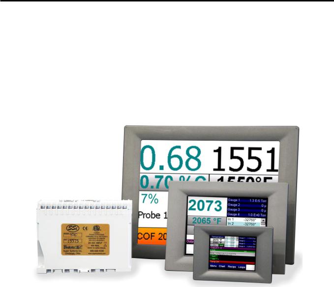
The 9130 is a single loop recipe programmable instrument with an internal timer commonly used on temper and freezer applications. The 9130 can provide automatic PID control of a single loop application using ramps, soaks, events and alarms. In addition to control, the 9130 provides full video recorder capabilities utilized through the color touch screen interface. This interface is available in 3.5”, 5.7” and 12” sizes. Included TS Manager software allows remote access from a
PC for viewing and printing of historical data. Remote access to the instrument for setup archiving, recipe management and backup, remote control or remote view can all be performed using the Configurator software that ships with the product. Communications are provided via RS 485 Modbus communications and Ethernet.
Series 9130 Operations Manual Rev - |
7 |

Approximate Box Dimensions |
2.75" x 4" x 4.5" |
Power Requirements |
24VDC, 4 Watts |
Digital Output Rating |
300VAC / 1 AMP |
Analog Output Load Rating |
1000 Ohms (Total) |
Controller Enclosure Rating |
IP10 – hand protected |
Number of RS232 Ports |
Two (2) |
Number of Ethernet Ports |
One (1) |
Number of RS485 Host Ports |
One (1) |
Number of RS485 Slave Ports |
Two (2) |
Number of Internal Relays |
Eight (8) |
Number of Analog Inputs |
Three (3) |
Number of Analog Outputs |
Two (2) |
Number of Digital Inputs |
Four (4) |
Number of Control Loops |
One (1) |
!The Model 9130 is powered by 24 VDC, not LINE Voltage. Please be careful when connecting power to this controller. Connecting anything other than 24 VDC will cause serious damage.
The variety of input and output combinations allows SSi to configure the Model 9130 to control temperature.
The product is available in three different screen sizes. 3.5”, 5.7” and 12”.
Mounting
The SERIES 9130 Operator Interface mounts into a panel or on a plate by using the enclosed mounting brackets. A rectangular cutout is required; the size of the cutout is determined by the operator interface size. These units, along with an optional SSi SR3, 6, or 9 analog input board, will mount on a commercially available DIN rail. This can be mounted on the sub-panel on the side of an enclosure for the convenience of the control system.
Series 9130 Operations Manual Rev - |
8 |

Dimensional Drawings
SERIES 9130 Controller Dimensions
24V DC Power Supply Dimensions
Series 9130 Operations Manual Rev - |
9 |
3.5” Operator Interface Cutout dimensions
5.7” Operator Interface Cutout dimensions
12” Operator Interface Cutout dimensions
Series 9130 Operations Manual Rev - |
10 |
Wiring
Wiring to the SERIES 9130 eSPP’s operator interface can be done using 232 or 485 to two connectors, comm1 (232) or comm3 (485). The terminal strip on the lower right rear corner of the operator interface is used to connect 24VDC power. The DB-9 port A connection is used to connect the display via 232 to the SERIES 9130 PID controller. The controller is connected via RS485 communication to the single-loop controllers.
Electrical Installation
The Model 9130 requires 24VDC, 4 Watt, 60 Hz, single-phase power. A 24 VDC power supply is required and is generally included as part of the Model 9130 system. This power supply has a universal input that can accept between 60 and 265VAC. Power should be applied in accordance with the electrical drawings that have been supplied. Since each installation is unique to the site, the customer is responsible for providing adequate power and making it available to the Model 9130 power supply.
SSi requirement:
MOV’s must be wired across the isolation relay coil terminals on all isolation relays that are connected to solenoids. Further… MOV’s must be connected across the HOT and NEUTRAL wires when the solenoid is wired to them. IT IS AN ABSOLUTE MUST to have the MOV’s at BOTH LOCATIONS.
Series 9130 Operations Manual Rev - |
11 |

Pin Out
9130 Pin Out
A wiring diagram of the SERIES 9130 controller can be found in Appendix B.
Ancillary Items
The following items can be included with the SERIES 9130: a flash card, a flash card reader, a touch screen, an RS232 cable, an RS485 cable, a 24V DC DIN rail mount power supply, and a software CD with Configurator, the Configurator manual, TS Manager, and .NET 2.0. The flash card installs the operator interface and the flash card reader connects to a Windows® based computer.
The operator interface includes connections for a mouse and a keyboard. These may be connected to the operator interface via USB, allowing the operators to use a mouse and keyboard instead of the touch screen.
Series 9130 Operations Manual Rev - |
12 |
The following table shows the ancillary items and their part numbers.
Part |
Part Number |
|
|
3.5" Operator Interface |
13498 |
|
|
5.7" Operator Interface |
13448 |
|
|
12" Operator Interface |
13455 |
|
|
TS Manager/PC Configurator Software |
13339 |
|
|
RS485 comms cable for 12.1” and 5.7 “ |
20576 |
|
|
RS485 comms cable for 3.5” |
20635 |
|
|
Flash Card |
13335 |
|
|
Flash Card Reader |
13333 |
|
|
RS232 Cable |
33027 |
|
|
24V DC Din Rail Mounted Power Supply |
31135 |
|
|
Setup
The SERIES 9130 setup consists of setting the local time if required. As shipped from the factory the communications ports are set at 19200 baud in Modbus mode.
Time will be set for local time in Cincinnati, Ohio (EST /EDT) or time zone of location of city and state on sales order. For instruction on adjusting these values, please see Chapter 3 - Configuration.
Additional Features
The Operator Interface (touch screen) contains a removable compact Flash Card that can be used to transfer data from the Model 9130 to a computer. It is located on the back of the touch screen (see Flash Card & Flash Card Reader section for more details).
Also included is a Utility Software CD that includes SSi’s TS Manager. TS Manager is a utility program that can be loaded onto any Windows® based computer (operating Windows 98® or higher). This software will allow the computer to read the data from the TS Flashcard, and allow it to be viewed in a manner that is similar to a strip chart recorder.
Ethernet Connections
The Ethernet connection has three distinct uses. First, should the Operator Interface fail, the Ethernet connection allows a laptop to be connected via a crossover cable to the SERIES 9130 DIN rail mounted unit using Internet Explorer Browser. This connection can act as a LIMITED
FUNCTION “operator interface” until the Operator Interface can be repaired or replaced. The
Series 9130 Operations Manual Rev - |
13 |

laptop needs to be operating a WINDOWS 98® or higher with Internet Explorer. The default IP address is 192.168.0.200. If you are experiencing problems please call 800-666-4330 and talk with our computer communications personnel. Secondly, the Ethernet port can be used for communications to a SCADA software package. Call us at 800-666-4330 if you are interested in this option. The third use for the Ethernet Port is the primary communications connection for the Configurator 2.0 Software.
Instrument Start-up
On power-up, the Operator Interface will display a Microsoft Windows desktop screen for a few seconds and then switch to the default Status screen.
Flash Card & Flash Card Reader
!Never remove the flash card when the Operator Interface is “ON”.
To properly shut down the Operator Interface, press the Menu button on the default status screen. Once the menu has been displayed, select the Shutdown option. At the prompt, press Yes to shut down the Operator Interface. See the Chapter 2 – Configuration section for information on navigating and using the menu system. This will display a conventional Microsoft Windows screen. Sliding the black switch to the OFF position (located directly over the green power connector, on the back of the Operator Interface) will turn off the power to the Operator Interface.
Once the Operator Interface is turned off, remove the compact flash card cover at the top of the display unit, exposing the card. Press the black release button and the card will pop out of the slot. To replace the flash card, simply return the card to the slot making sure that the release button is in its UP position, and replace the flash card cover to its proper position. To restore power to the unit, move the black switch to the right or ON position.
Operator Interface Screen Saver
The Operator Interface has a default screen saver. It automatically “blanks” the screen after ten
(10) minutes of non-activity. To disengage the screen saver, simply touch the screen and it will reappear.
Default Status Screen
Display
The Status Display shows the temperature controller information as well as any auxiliary analog inputs, the status of the timer, and an overview of the programmer. There are five active buttons on the Status Display: Menu, Chart, Recipe, Loops, and Ack.
The Menu button will display the configuration menu.
The Chart button will display the video recorder screen. Use of the Chart Display is explained below.
Series 9130 Operations Manual Rev - |
14 |

The Recipe button will switch to the Program Display. This is a companion display to the status screen and is described below.
The Loops button will display the main control loop, Temperature, as well as the timer status and any auxiliary analog inputs.
The Ack (Alarm Acknowledge) button is used to acknowledge an alarm. The alarm message is displayed directly under the recipe display. Is this only present when an alarm is going off.
Menu
There are three levels of menus in the SERIES 9130.
The first level is the operator level. These are functions or operations that are typically handled by the furnace operator. This menu is accessed without the need for a pass code.
The second level is the supervisor level. This level requires the entry of a level 1 or a level 2-pass code.
The third level is the administrator level. This requires the level 2-pass code ONLY.
As shipped, the supervisor and administrator level
codes are set as 1 and 2 respectively. The pass codes can be changed at the Passcode and Alarm Screen.
Note: Any level can access a lower level screen. For instance, the Administrator level passcode can access all of the Supervisor and Operator level screens.
The menu items are explained in detail in Chapter 2 – Configuration.
Chart
The Chart Display shows between 1 hour and 24 hours of process variable data on the screen and can be scrolled back to view all of the data stored on the hard drive. The vertical timelines change as the time changes on the screen. Any trend charts that have been created through the Configuration menu are accessible here. See the Chapter 2 – Configuration section for more information on creating trend charts.
The function buttons run along the bottom of the screen.
The Trend Lines button -  - will allow the user to select or de-select the trend lines on the trend chart to display. If the checkbox next to each trend line is checked, then that trend line will be displayed.
The Datagrid View button -  - will display a screen with the trend data in a grid format instead of with trend lines. The trend data is shown in 1-minute intervals. Clicking on the OK button on this screen will close the screen down and return to the Chart Display screen.
The Refresh button -  - will refresh the screen’s trend data if the screen is not in real-time mode.
Series 9130 Operations Manual Rev - |
15 |
The left-pointing green arrow button -  - will move the chart’s view backward in time by the specified chart interval.
The chart interval button -  - will determine the number of hours displayed on the trend chart. The options are: 1 Hour, 2 Hours, 4 Hours, 8 Hours, 12 Hours, or 24 Hours.
The right-pointing green arrow button -  - will move the chart’s view forward in time by the specified chart interval.
The right-pointing arrow with the vertical line next to it button -  - will put the chart into real-time mode if it is not in real-time mode, or take the chart out of real-time mode if it is. When in real-time mode, the chart will automatically be updated once a minute.
Chart Sub Menu
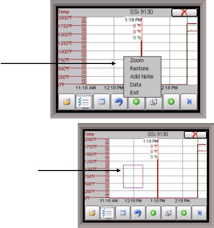
There is a sub-menu available by putting a finger or a stylus anywhere on the chart and holding it there for a couple of seconds. The sub-menu will have the following options available: Zoom, Restore, Add Note, Data, and Exit.
The Zoom option will allow the user to zoom in on a particular part of the screen. Once this has been selected, the user can take a stylus or a finger and create a box around the desired data. Once the user releases the stylus or finger, a zoom is no longer possible, and the user will need to re-select the option from the sub-menu to zoom in again.
The Restore option will back out of any zoom options that have been performed and display the chart screen as it initially was.
The Add Note option allows the operator to enter a note on the chart, similar to writing on a paper chart. The note shows up when the chart is printed out using the utility software included with the SERIES 9130 instrumentation. Pressing the Add Note option displays a screen where the operator can enter the
operator ID or initials and a note. The user has the option to enter a note using the operator interface keyboard, where he or she will be able to type in the note; or the user can use the Signature mode, which will allow them to write a note using a stylus.
Series 9130 Operations Manual Rev - |
16 |

The Data option will show the trend data as a data grid instead of the trend lines on a chart. This
functionality is exactly the same as if the user pressed the Datagrid View button -  - from the chart screen.
Exit will close out the sub-menu without selecting an item.
Pressing the red ‘X’ in the top right-hand corner of the screen will take the user back to the status screen.
Recipe
Pressing the Recipe button on the main status screen displays the recipe screen, which will allow the user to load up an existing recipe and start it, or see the currently running recipe.
The recipe screen shows the last program loaded into the program run buffer and its status. If the program is running, the active step number is highlighted green. When the step is highlighted green, then the recipe is running on that step. When a step is highlighted yellow, the recipe is in hold on that step. A red Acknowledge button in the bottom left corner of the screen displays an alarm condition. Note – the main status screen will also show the recipe running status, as well as run time and remaining time for the step as well as the entire recipe.
The recipe screen has a total of seven buttons that will allow the user to load up a recipe, as well as control the recipe and acknowledge an alarm.
The Advance button will advance the recipe to the next step in the recipe. The user will need to confirm the advance command.
The Hold button places the displayed recipe program in hold. Once a decision is made that affects the recipe, it may be continued by pressing the Resume button. Note – When a recipe is put into hold status, the text on the Hold button will change to “Resume”. When the step is started up again, the text on the button will change back to “Hold”. When a recipe step is in a hold status, the step will be highlighted yellow. The user will need to confirm the hold or resume command.
The Stop button stops the recipe program that is currently running. Stop means exactly that! It stops the program. It is NOT a hold button. See the description for the hold button above. To restart the program if it has been stopped you must use the Load button, enter the recipe number, and then highlight the segment number of the recipe that you want to start with and start the recipe again. The user will need to confirm the stop command.
The Soak button allows you to enter a new value for the time remaining in the current soak or ramp cycle only – future soak or ramp cycle times cannot be modified. The step must be a soak or ramp cycle for a change in soak/ramp time to be adjusted.
The Acknowledge button will acknowledge the alarm. In most cases, it will be acknowledging end of soak. The alarm must be acknowledged to allow the program to go to the next step. Note – The Acknowledge button is only visible when an alarm condition is present. Once the condition is acknowledged, the Acknowledge button will become invisible again.
Series 9130 Operations Manual Rev - |
17 |

The Load button allows the operator to enter the recipe number to be run and to view the recipe before pushing the Run button. Pushing the Run button starts the recipe. If a recipe program is running and the operator enters a new recipe program it can be viewed and modified. The recipe does not become active until the Run button is pushed. Pressing Run places the program currently being viewed in the active memory and will begin to run the new recipe. To select the recipe to view or edit, click on the recipe number button in the top left corner of the screen. This will display a screen where the user will be able to load up a valid recipe (range 1 – 300). The program can be started in any step by clicking on the step number button next to the “Step” text and entering the new step number (range 1 – 24), and then pressing the Run key.
While reviewing the program that is about to be run, each step can be modified. Highlight a step number and click on the Edit button. The opcode can be changed with the drop down list at the top. This list can be sorted alphabetically by click on the “Alphabetical” checkbox. The parameters of the opcode can be modified on this screen as well. See the Chapter 5 – SERIES 9130 Opcodes section for details about each opcode. Click on the OK button to accept the changes; click on the Cancel button to ignore the changes. Note – Any change to the recipe is a one-time edit, and will not affect the recipe that is saved on the 9130 controller. Click on the Cancel button on the Load Recipe screen to cancel loading a recipe and return to the main recipe screen.
The Return button returns you to the main status screen.
Loops
This screen will display the program loops for the 9130. Currently, there is only one loop to display – temperature.
The current process variable is displayed at the top, with each loop set point displayed beneath the process variable. The operator can change the process set point by touching the screen area below the large process variable numbers. When pressing the Temperature set point, a numeric keypad is displayed, showing the current value and allowing the operator to enter a new set point by simply pressing on the appropriate numeric keys. Once the correct set point has been entered, press the OK key to make the change. When the OK key is pressed the display returns to the Loops Screen. Another active key within the Loops Screen is the
Auto/Man (Auto/Manual) button. Pressing that button toggles the controller’s mode between Auto and Manual. In the manual mode, pressing the percent output button on the Loops Screen (next to the Auto/Man button) displays a numeric keypad, allowing a % output to control the “loop” in a manual mode to be entered. If a timer is running, the status will be displayed at the top right of the screen. Any load T/Cs that are actively communicating will be listed in the box to the right of the setpoint/percent output values. If an alarm condition is present, the alarm text will be displayed below the loop information. If the alarm needs acknowledging, then the Alarm Ack button will be displayed in the bottom left corner. If the alarm is part of a recipe step, the alarm will need to be acknowledged before the recipe can move to the next step.
Series 9130 Operations Manual Rev - |
18 |

The Loops Screen also allows you to move back to the default Status Screen by pressing the Return.
Ack (Alarm Acknowledge)
The Ack (Alarm Acknowledge) button will allow the user to acknowledge any alarms that have been configured, or that have been made part of the recipes that run on the SERIES 9130. If a recipe has an alarm as a step, the alarm must be acknowledged before the recipe will continue to the next step.
Data Logging using Flash Card
!NOTE: See Warnings with respect to removing the Flash Card.
The Advantech TPC-642S/642-SE touch screen Operator Interface utilizing a Compact Flash Card allows the unit to data log the parameters setup by a qualified SSi technician. Should a
customer not take the data offline in a timely manner, the data will be over-written, the oldest data being over-written first. Here is how it works:
1.When the Operator Interface detects that there is less than 5% disk space left on the compact flash card, an alarm will be displayed on the main interface screen stating "x% disk space remaining (overwrite at 3%)". In the upper right corner, an ALM is indicated, but because it is not a communications alarm or a 9130 device alarm, the background remains green. This alarm will remain active until more than 5% of disk space is available for writing data log files.
2.If the user does not copy the log data from the disk, it will eventually fall to 2% disk space. At this point, the touch screen will select the oldest compressed file and delete it. It then checks to see if 3% remains. It repeats this procedure until 3% disk space remains. At this point the alarm message changes to "Overwriting data log data!” Because this allows the system to seesaw between 2% and 3%, it will continue to display "Overwriting data log data!" until somebody offloads the files.
Technical concerns and details:
1.If there are not enough compressed files to bring the free space up to 3%, the system will hunt down and kill hourly files. This should only happen if compression would not be running for some reason.
2.If all compressed files and hourly files have been removed and there is still not enough disk space (perhaps a problem with the compact flash card), the data logger will not write to the disk until the condition is remedied. (Alarms continue to display).
3.The data log data alarm is the lowest priority. The alarm priorities are touch screen communications, then 9130 controller/programmer, then disk space.
See the Flash Card Management Section for more information.
Series 9130 Operations Manual Rev - |
19 |
Chapter 2 - CONFIGURATION
Menu (Configuration)
The Configuration Menu is entered through the Menu key that is part of the four buttons running along the bottom of the Default Display Screen.
Pressing the Login key at the bottom of the screen will allow the user to enter a login user and password. Note – users can be set up through the Security menu option in this menu. User names and passwords are case sensitive. There are three levels of security for the menu system: Operator, Supervisor, and Administrator. Pressing the Login button will allow the user to enter a user name and password to log in. When the menu screen is first displayed, the operator-level menu options are visible.
The list of the operator-level menu options is:
Logs
Slave Communications Status
Load TC/Auxiliary Analog Input
Manual Event Control
Shutdown
The list of supervisor-level menu options is:
Logs
Slave Communications Status
Load TC/Auxiliary Analog Input
Manual Event Control
Shutdown
PID Loop Setup
Recipe Edit
Load T/C Configuration
Trend Chart Edit
The list of administrator-level menu options is:
Logs
Slave Communications Status
Load TC/Auxiliary Analog Input
Manual Event Control
Shutdown
PID Loop Setup
Recipe Edit
Load T/C Configuration
Trend Chart Edit
Communications Setup
Series 9130 Operations Manual Rev - |
20 |

Slave Instrument Setup
Zone Assignments
Furnace Setup
Default Wait Limits
Alarm Setup
Relay Assignments
Analog Input Setup
Analog Output Setup
Alarm Polarity
Event Hold/Reset
Security
Curve Entry
Alternate PID Setup
Aux Analog Input Setup
Calibration
Configuration
A/I Module Offset Correction
PV Switching
T/C Correction Curves
Generic Instrument Setup
Tuning Assistant
Analog Input Correction Curves
Timer Setup
Instrument Calculation
The SSi code of the day can also be used to log in to the menu system. No user name will need to be entered when entering this code. Currently, the menu list is identical to the administrator-level list. The SSi code of the day is typically used for in-house configuration prior to shipment. The code can only be provided by Super Systems at 800-666-4330.
To select any of the menu options, highlight that item by clicking on it, and click on the Detail button. The Return button will return the user to the default display screen.
Logs
The Logs screen will allow the user to view three different types of logs – System, Alarms, and Cycle.
Clicking on the button that displays the log type (System Log, Alarm Log, or Cycle Log) will allow the user to select the type of log file to view.
The green directional arrows will display the previous items in the log or the next items in the log, if the log items are longer than one screen. The drop down list in between the directional arrows will allow the user to select the date of the log items to view.
The Return button will return the user to the menu screen.
Series 9130 Operations Manual Rev - |
21 |

Slave Communications Status
This page is a display of the current process variables of each of the slave instruments communicating with the 9130 controller. These values are display-only, and cannot be modified from this screen.
There are five possible messages that can occur to describe the instrument communications status.
N/A – No instrument is connected
Bad – No communications exist
??? – Communications exist, but there are frequent errors
?OK – Communications exist, but there are occasional errors
OK – Communication is established and working properly
For set-up of the auxiliary instruments go to the menu item “Slave Instrument Setup”
The Return button will return the user to the menu screen.
Load TC/Auxiliary Analog Input
The Load TC/Auxiliary Analog Input screen will show the values for the load TCs and the auxiliary analog inputs. These values are display-only, and cannot be modified from this screen.
Manual Event Control
Events are assignable outputs, used in recipes/programs. Typically, they are used to signal the recipe is complete, to turn process gases off and on, and tell the equipment to do a variety of tasks. The Manual Event Control submenu allows the user to force the events off or on. So, say they need to manually turn on nitrogen, and there was an event relay assigned to that from the controller, they could go into manual event control, and turn on the event that is assigned to nitrogen
The Manual Event Control menu option shows the user all of the events (0 – 47) and their current status. It also allows the user to manually control the status of any event by clicking on the value. To change the
status, highlight the specific event and click on the Edit button. The user will be able to select either an On value or an Off value.
Clicking on the OK button will set the value, while clicking on the Cancel button will cancel the action. The Return button will return the user to the menu screen.
Series 9130 Operations Manual Rev - |
22 |

Shutdown
The Shutdown selection will display a screen asking whether or not to shutdown the interface of the SERIES 9130. When the operator interface is shutdown, the SERIES 9130 controller is still functioning. IT can be monitored by connecting the ETHERNET connection to a laptop computer, using Internet Explorer, and assigning a legitimate IP address. Choosing Yes displays a typical computer desktop screen with the Start button in the bottom left-hand corner. The power to the operator interface can now be turned off without upsetting any of the settings. Choosing No displays the initial Status Screen. Note -Shutting down the Operator Interface does not shutdown the SERIES 9130 Controller.
PID Loop Setup
PID is the tuning parameters entered for each Process Variable loop.
Prop Band (0 for On/Off)
This is the proportional band field. P = Proportional (Prop Band). This is a field in which you want to stay around the setpoint. The range 0 – 3276.0.
Reset
This is the reset field. I = Integral (Reset). This is the actual temperature being monitored over a period of time and then averaged to keep within the Proportional band. The reset is in repeats per minute. This affects the output of the controller. It will be proportional to the
amount of time the error is present. This helps to eliminate offset. The range 0 – 327.67.
Rate
This is the rate field. D = Derivative (Rate). This is the sudden change or rate in the temperature. This rate is in minutes. This affects the controller output which is proportional to the rate of change of the measurement and will control the amount of output by time restraints. Thus derivative takes action to inhibit more rapid changes of the measurement than proportional action. Derivative is often used to avoid overshoot. The range 0 – 327.67. The rate is not typically used for heating/carbon.
Mode
This is the mode of the loop. The values are: Dual Reverse, Single Reverse, Dual Direct, or Single Direct. Dual – This has two output relays which can increase and decrease to achieve the SP.
Single – This has one relay which works in only one direction to achieve the SP.
Direct - If the PV - SP equals a positive number and the output would bring the PV down toward setpoint that is direct.
Reverse – If the PV - SP equals a negative number and the output would bring the PV up toward setpoint then that is reverse
Example: If a 12 mA output drives a 0 degree F temperature (PV) UP to a 1200 degree F temperature (SP), this would be REVERSE, and since this would take a SINGLE output from the controller, the Mode for the Temperature Loop is Single Reverse.
Integral Preset
This field provides an offset for the starting point for PID control, also referred to as “Load Line” or “Manual Reset”. The range is –100 to 100.
Cycle Time
This field is typically set to the valve travel time multiplied by 1.5. The range is 0 – 500.
Series 9130 Operations Manual Rev - |
23 |
Setpoint Change Limit
This is a smart time feature that allows Process Loop to use PB only without Reset until the Process Variable drops below the percent output set under this category.
It is used to eliminate overshoot.
The Output percentage selected under this category must be above the normal operating output percentage of the furnace at heat.
The options are: OFF, 80%, 70%, 60%, 50%, 40%, 30%, or 20%.
Example: If the furnace runs at 40% output at heat for the maximum load, the setpoint change limit should be set to 60%.
Low Limit
This is the low limit for the loop. The range is –100 to 100.
High Limit
This is the high limit for the loop. The range is –100 to 100.
0 Setpoint Stops Control
If the Setpoint is zero, then all outputs are turned off. The option is either Yes or No.
IN1 high limit shuts down ctrl
If input 1’s high limit is reached, then all outputs are turned off. The value can either be Yes or No.
IN2 high limit shuts down ctrl
If input 2’s high limit is reached, then all outputs are turned off. The value can either be Yes or No.
IN3 high limit shuts down ctrl
If input 3’s high limit is reached, then all outputs are turned off. The value can either be Yes or No.
PID Auto Switch
This is the PID auto switch field. The value can either be Yes or No.
Switch Point PID 1 -> 2
This is the PID Switch Point field. This is used in conjunction with the PV Switching feature. See the PV Switching section for more information. The range is –300 to 4000.
Switch Point PID 2 -> 3
This is the PID Switch Point field. This is used in conjunction with the PV Switching feature. See the PV Switching section for more information. The range is –300 to 4000.
Overshoot Limit Gain
This is the Overshoot limit gain field. When calculating the control action, sometimes the calculation would call for more than 100% which is not possible. The output is limited to 100% or whatever was set in the High Limit field. The difference of the unlimited minus the limited is multiplied by the overshoot limit gain and divided by 100. This is subtracted from the control output. If the gain is 0 there is no effect. Under normal control the unlimited equals the limited and there is no effect. If there is a big change where the control loop drives hard, then the effect is to limit the drive as it approaches setpoint and limit the overshoot.
The limited is the values set in the upper and lower limits fields. The unlimited would be what is calculated before limiting. For a big setpoint change, the calculations may compute 150% output, but the true output is limited to the upper limit.
The range is 0 to 9999.
Series 9130 Operations Manual Rev - |
24 |

Setpoint Lower Limit
This is the lower limit of the setpoint. The range is –300 to 9999.
Setpoint Upper Limit
This is the upper limit for the setpoint. The range is –300 to 9999.
Cascade SP Lower Limit
This is the cascade setpoint low limit. The 9130 uses the difference between the cascade SP lower limit and the cascade SP upper limit and multiplies that value by the % output of the load loop. It then offsets this value by the cascade SP lower limit and feeds the furnace loop this value as a setpoint.
Cascade SP Upper Limit
This is the cascade setpoint upper limit. The 9130 uses the difference between the cascade SP lower limit and the cascade SP upper limit and multiplies that value by the % output of the load loop. It then offsets this value by the cascade SP lower limit and feeds the furnace loop this value as a setpoint.
Example:
Cascade SP Lower Limit: 0 Cascade SP Upper Limit: 2000
The load has a setpoint of 1700 and it is at 37 % output. The furnace setpoint will be calculated as follows: (2000 – 0) * 0.37 + 0 = 740.
The Return button will return the user to the menu screen.
Recipe Edit
This option will allow the user to edit a recipe that is stored on the 9130 controller. The Select Recipe button will allow the user to select
which recipe to load (1 – 300). Once the recipe has been selected, the recipe will be displayed on the screen.
The higher recipe steps can be viewed by holding a finger or stylus on the screen and scrolling up or down.
To edit a specific step, highlight that step and press the Edit button. This will allow the user to select a different Opcode to use, or to change the information entered for the current Opcode. See the SERIES 9130 Opcodes section for more information on each Opcode and its purpose.
To insert a step into the program, highlight the step
number for the step, and press the Insert button. The user will have to confirm the insert. Once this has been confirmed, the user will be able to select the Opcode to use. Note – Inserting a step will push every step after down one, so an Opcode at step 24 will be lost.
To remove a step from the recipe, highlight the step number to remove, and press the Delete button. The user will have to confirm the delete. Once the delete has been confirmed, the step will be deleted and every step after will be moved up one step. Blank step numbers will be replaced with a NO-OP Opcode.
Press the Save button to save the changes that have been made. The recipe can be saved as any valid recipe number (1 – 300). If the desired recipe number already contains a recipe, the user will have to confirm the save before the old recipe will be overwritten.
If the user wishes to delete an entire recipe, they have one of two options. First, they could load up the desired recipe and change every step to the NO-OP Opcode and save those changes; Or, they could save the 24-step “blank” (NO-OP) program that is loaded up when the Recipe Edit screen is first displayed as the desired program number. This will save the “blank” recipe to the desired recipe number location.
Series 9130 Operations Manual Rev - |
25 |

The Return button will return the user to the menu screen.
Load T/C Configuration
Configuration of any analog input device must be completed under this menu item.
Load TC Enable
This value will manually toggle between on, on + alarms, and off.
On – T/C Enabled
On + Alarms – T/C Enabled, Programmer alarm114 provided if out of band (Default wait limits)
Off – T/C not enabled
Control TC
This value allows the user to set the TC to be part of the group of Load TCs that can hold the program if it is out of
band. The values are active or not active (shown as blank).
TC 1 – 30
This value allows the user to manually turn the T/C from active to not active, shown as blank, to be part of the group of TCs that can hold the program if it’s out of band. TC 28 – TC 30 correspond to Analog Input 1 – Analog Input 3. The values are active or not active (shown as blank).
Load T/C Alm On Delay (Sec)
This option will allow the user to set a delay time, in seconds, before the load T/C alarm is activated. The range is 0 – 32767.
The Return button will return the user to the menu screen.
Trend Chart Edit
This menu option will allow the user to add, modify, or delete trend lines in a trend chart file, as well as the trend chart files themselves. The trend lines are the number of variables displayed on one screen. For example this could be a control, overtemp, or load thermocouple on a batch furnace. Or it could be one thermocouple from eight temper furnaces. There is not a maximum for template selections, but the number of variables displayed on one screen must be a consideration in this process. The buttons across the top of the screen – Open, New, Delete, Save, and Save As – deal with the trend chart files themselves, not the individual trend lines.
Open will allow the user to select a trend chart file to open up to edit.
New will create a new trend chart file to begin adding trend lines to. Delete will delete a specified trend chart file.
Save will save all changes to the current trend chart file that have been made.
Save As will allow the user to save the current trend chart file as a new file with a different name.
Series 9130 Operations Manual Rev - |
26 |

Once a new trench chart file has been created, or one has been opened, trend lines can be added, modified, or deleted. Add will add a new trend line to the file. Edit will allow the user to edit the information for a specific trend line. Delete Line will delete the specified line from the chart file.
Adding or editing a trend line will involve the following parameters: Name – the name of the input, for example “Temp
ACT” which would be the actual temperature of the input. It is a good idea to shorten the names so that they still make sense, but do not take up as much space.
Data – This will determine where the data is coming from. The user can click on the box to select from the list of data logged points in the 9130. Some of the points have a name, such as “Temperature” or “Temperature SP”, but others will just show the register in the 9130 that has been logged.
Min – the minimum displayed scale value on a chart. Max – the maximum displayed scale value on a chart.
Expression – every input requires an expression to
be calculated and displayed correctly. This is because the registers in the 9130 hold only integer values, so any value that requires a decimal point needs to be set up properly for the display. For example an expression for temperature would be x (1750 = 1750). For a value such as carbon or millivolts, the expression would be x * 0.01 (150 = 1.50) or x * 0.1 (805 = 80.5).
Format – the value displayed on the chart display of the operator interface. A short custom description can be added here. For example, to display one (1) decimal point, enter a value of “#0.0”. For carbon values, enter a value of “#0.00” for 2 decimals. This would display a value like “0.81”. Entering “#.00” would display a value of “.81”. #0 or 0 will display integer values.
Color – The box next to the format box will allow the user to apply a color to the trend line to differentiate it from other trend lines on the chart.
Units – The type of units used for the trend.
Line Width – a numeric value for the thickness of the trend line. A 1 is a thin line; A higher value = thicker line width.
Sample – a number is entered here to test the expression and verify that formatting is correct.
Test – Press the test button to calculate the expression with the value entered in the sample parameter. For example with an expression of x*.1 and a value of 250 entered in the sample parameter will display a 25.0.
The Set button will save the values entered. The Cancel button will cancel the information and make no changes.
The OK button will close the screen and prompt the user to save any changes if changes have been made.
The Cancel button will close the screen and return to the menu screen.
Series 9130 Operations Manual Rev - |
27 |

Communications Setup
Warning: Changes to this screen should not be made without consulting SSi at 800-666-4330.
This screen will show the Ethernet and RS-232/RS-485 communications information for the 9130 controller.
IP Address
This will identify the IP address of the controller. This is necessary if the Touchscreen will be communicating to the 9130 over Ethernet communications. The IP address must be in the “xxx.xxx.xxx.xxx” format.
Subnet Mask
This will identify the Subnet mask of the controller. This is necessary if the Touchscreen will be communicating to the
9130 over Ethernet communications. The Subnet mask must be in the “xxx.xxx.xxx.xxx” format.
Gateway
This will identify the IP gateway of the controller. This is necessary if the Touchscreen will be communicating to the 9130 over Ethernet communications. The IP gateway must be in the “xxx.xxx.xxx.xxx” format.
RS-232B Baud
This will set the baud rate for RS-232 communications. This is necessary if the Touchscreen will be communicating through the Com ports. The list of options is:
1200 |
14400 |
57600 |
2400 |
19200 |
76800 |
4800 |
28800 |
115200 |
9600 |
38400 |
|
RS-232B Mode
This will set the mode for RS-232 communications. This is necessary if the Touchscreen will be communicating through the Com ports. The list of options is:
Modbus
Cal Term Modbus/DF1 Master
Host 485 Baud
This will set the baud rate for RS-485 communications. This is necessary if the Touchscreen will be communicating through the Com ports. The list of options is:
1200 |
14400 |
57600 |
2400 |
19200 |
76800 |
4800 |
28800 |
115200 |
9600 |
38400 |
|
Host 485 Mode
This will set the mode for RS-485 communications. This is necessary if the Touchscreen will be communicating through the Com ports. This setting is fixed at Modbus.
Host 485 Address
This will set the address for RS-485 communications. This is necessary if the Touchscreen will be communicating through the Com ports. The range is 1 – 247.
Series 9130 Operations Manual Rev - |
28 |
Slave 1 Baud
This will set the baud rate for Slave 1 communications. The list of options is:
1200 |
14400 |
57600 |
2400 |
19200 |
76800 |
4800 |
28800 |
115200 |
9600 |
38400 |
|
Slave 1 Mode
This will set the mode for Slave 1 communications. This list of options is:
MMI
Modbus Master
Yokogawa
Modbus Host
Slave 2 Baud
This will set the baud rate for Slave 2 communications. The list of options is:
1200 |
14400 |
57600 |
2400 |
19200 |
76800 |
4800 |
28800 |
115200 |
9600 |
38400 |
|
Slave 2 Mode
This will set the mode for Slave 2 communications. This list of options is:
MMI
Modbus
ADAM
SSi Analog Input Board
Yokogawa
RS-232A Baud
This will set the baud rate for RS-232 communications. This is necessary if the Touchscreen will be communicating through the Com ports. The list of options is:
1200 |
14400 |
57600 |
2400 |
19200 |
76800 |
4800 |
28800 |
115200 |
9600 |
38400 |
|
RS-232A Mode
This will set the mode rate for RS-232 communications. This is necessary if the Touchscreen will be communicating through the Com ports. This list of options is:
Cal Term
Modbus
The Return button will return the user to the menu screen.
Series 9130 Operations Manual Rev - |
29 |
 Loading...