


 Super Systems
Instruction Manual
Model AC20
Part No. 31069 - Standard Atmosphere Controller
with expanded event capability
August 2004
INDEX |
|
MOUNTINGREQUIREMENTS ..................................................... |
1 |
OUTLINE AND CUT OUT DIMENSIONS ...................................... |
2 |
CONNECTION DIAGRAMS ......................................................... |
3 |
PRELIMINARY HARDWARE SETTINGS .................................... |
14 |
SECURITY CODE SETTING MODE ........................................... |
17 |
RUN TIME AND CONFIGURATION MODES .............................. |
20 |
General notes about graphic symbols ............................. |
20 |
Keyboard description ....................................................... |
20 |
CONFIGURATION MODE .......................................................... |
22 |
RUN TIME MODE ...................................................................... |
44 |
Display function ................................................................ |
44 |
Indicators .......................................................................... |
46 |
Bargraph description ........................................................ |
48 |
Direct access to the set point ........................................... |
49 |
Manual function ................................................................ |
49 |
Special output features ..................................................... |
50 |
Burn off procedure ............................................................ |
51 |
Probe test procedure ........................................................ |
53 |
Serial link ......................................................................... |
54 |
Lamp test ......................................................................... |
55 |
SMART function ................................................................ |
55 |
COF and H2F adjustment diagram .................................... |
57 |
Parameter protection ........................................................ |
58 |
RUN TIME PARAMETER MODIFICATION |
................................... 58 |
ERROR MESSAGES ................................................................. |
83 |
GENERAL INFORMATION ......................................................... |
85 |
MAINTENANCE ......................................................................... |
93 |
DEFAULT PARAMETERS ........................................................ |
A.1 |
ALGORITHMS ........................................................................ |
B.1 |
CALIBRATIONPROCEDURE ................................................... |
B.1 |

MOUNTING REQUIREMENTS
This instrument is intended for permanent installation, for indoor use only, in an electrical panel which encloses the rear housing, exposed terminals and wiring on the back.
Select a location, for instrument mounting, where minimum vibrations are present and the ambient temperature is within 0 and 50 °C (32 and 122°F).
The instrument can be mounted on a panel up to 15 mm thick with a cutout 92 x 92.
For outline and cutout dimensions refer to Fig. 2.
The surface texture of the panel must be better than 6,3 m. The instrument is shipped with rubber panel gasket (50 to 60 Sh).
To assure the IP65 and NEMA 4X protection, insert the panel gasket between the instrument and the panel as shown in fig. 1.
While holding the instrument against the panel proceed as follows:
1)insert the gasket in the instrument case;
2)insert the instrument in the panel cutout;
3)pushing the instrument against the panel;
4)insert the mounting brackets as shown in fig.1;
5)with a screwdriver, turn the screws with a torque between 0.3 and 0.4 Nm.
Bracket
Gasket
Screws
Bracket
Fig. 1 |
Panel |
1

OUTLINE AND CUT OUT DIMENSIONS
4.92" (125 mm)
3.62"+ 0 . 0 3
4.92" (125 mm)
(92 mm + 0 . 8 )
3 |
) |
. 0 |
. 8 |
0 |
0 |
3.62"+ |
mm + |
|
(92 |
0.6" (15mm) max |
0.06" (1.5 mm) |
|
(108.5 mm) |
|
(97 x 97 mm) gasket |
4.17" |
|
x 3.8" |
|
|
3.8" |
3.78" (96 mm) |
5" (128 mm) |
0.63" |
(16 mm)
Fig. 2. OUTLINE AND CUT-OUT DIMENSIONS
2

CONNECTION DIAGRAMS
Fig. 3. REAR TERMINAL BLOCK
3

CONNECTIONS
Connections are to be made when the instrument housing is installed in its proper location.
MEASURING INPUTS
NOTE: Any external component (like zener barriers etc.) connected between sensor and input terminals may cause errors in measurement due to excessive and/or not balanced line resistance or possible leakage currents.
A) PROBE SENSOR INPUT (MAIN INPUT)
12 |
+ |
Sensor |
13 |
_ |
|
|
|
|
|
Shield |
|
12 |
+ |
Sensor |
13 |
_ |
|
|
|
|
|
G |
|
Fig. 4 MAIN INPUT WIRING
NOTES:
1)This input is isolated from others measuring inputs and digital inputs.
2)Don’t run input wires together with power cables.
3)When a shielded cable is used, it should be connected at one point only.
4

A.1) TEMPERATURE (THERMOCOUPLE) INPUT
+ 1
_ 3
 Shield
+ 1
_ 3 
 Shield
Fig. 5 TEMPERATURE INPUT WIRING
NOTES:
1)This input is not isolated from others measuring inputs and digital inputs.
2)Don’t run input wires together with power cables.
3)For TC wiring use proper compensating cable preferable shielded.
4)When a shielded cable is used, it should be connected at one point only.
A.2) AUXILIARY INPUT (CARBON MONOXIDE)
5
6
5
6
Fig. 6 AUXILIARY INPUT WIRING
+mA, or
_ V
 Shield
+
mA
_ or V
G
NOTES:
1)This input is not isolated from others measuring inputs
and digital inputs. A double or reinforced insulation between instrument output and power supply must be assured by the external instrument.
5

2)Don’t run input wires together with power cables.
3)Pay attention to the line resistance; a high line resistance may cause measurement errors.
4)When shielded cable is used, it should be grounded at one side only to avoid ground loop currents.
5)The input impedance is equal to:
< 5 Ω for 20 mA input
>200 kΩ for 5 V input
>400 kΩ for 10 V input
B) |
LOGIC |
INPUTS |
DIG. 1 |
|
|
8 |
|
|
|
|
DIG. 2 |
|
|
9 |
DIG. 3 |
|
|
|
|
|
|
10 |
|
|
|
11 |
|
IN 1
57 |
IN 2 |
58 |
IN 3 |
59 |
IN 4 |
60 |
56 |
Fig. 7.A - LOGIC INPUTS DIG 1 TO DIG 3 AND IN1 TO IN4 WIRING
6

IN 5
46 |
IN 6 |
47 |
IN 7 |
48 |
IN 8 |
49 |
45 |
Fig. 7.B - LOGIC INPUTS IN5 TO IN8 WIRING
Logic inputs from IN1 to In8 are optional.
NOTES:
1)Do not run logic input wiring together with power cables.
2)Use an external dry contact capable of switching 0.5 mA, 5 V DC.
3)The instrument needs 110 ms to recognize a contact status variation.
4)The logic inputs are NOT isolated from measuring inputs.
C.1) RELAY OUTPUTS
|
23 |
NC |
|
|
|
OUT 1 |
24 |
C |
|
||
|
25 |
NO |
|
|
|
OUT 2 |
26 |
C |
|
||
|
27 |
NO |
|
|
|
OUT 3 |
28 |
C |
|
||
|
29 |
NO |
|
|
Fig. 8.A RELAY OUTPUTS 1, 2, 3 WIRING
7

OUT 4 |
30 |
C |
|
||
|
31 |
NO |
|
|
|
OUT 5 |
15 |
C |
|
||
|
14 |
NO |
|
|
|
|
61 |
NO - OUT 10 |
OUT 10 |
|
|
|
NO - OUT 11 |
|
|
62 |
|
OUT 11 |
|
|
|
NO - OUT 12 |
|
|
63 |
|
OUT 12 |
|
|
|
NO - OUT 13 |
|
|
64 |
|
OUT 13 |
|
|
|
|
|
|
65 |
NO - OUT 14 |
OUT 14 |
|
|
|
C - OUT 10 to 14 |
|
|
66 |
|
|
|
Fig. 8.B RELAY OUTPUTS 4, 5 and 10 TO 14 WIRING
OUT 15 |
50 |
|
|
OUT 16 |
51 |
|
|
OUT 17 |
52 |
|
|
OUT 18 |
53 |
|
|
OUT 19 |
54 |
|
|
|
55 |
NO - OUT 15
NO - OUT 16 NO - OUT 17 NO - OUT 18 NO - OUT 19
C - OUT 15 to 19
Fig. 8.C RELAY OUTPUTS 15 TO 19 WIRING Outputs from OUT 10 to OUT 19 are optional.
The contact rating from OUT 1 and OUT 2 is 3A/250V AC on resistive load.
The contact rating from OUT 3 and OUT 4 is 2A/250V AC on resistive load.
The contact rating of OUT 5 is 1A/250V AC on resistive load. The contact rating from OUT 10 to OUT 19 is 0.5 A/250V AC on resistive load.
The number of operations is 1 x 10⁵ at specified rating.
8
NOTES: 1) |
To avoid electrical shock, connect |
power line at |
the end of the wiring procedure. |
2)For power connections use No 16 AWG or larger wires rated for at last 75 °C.
3)Use copper conductors only.
4)Don’t run input wires together with power cables.
5)When a relay output is used to drive a low power signal (PLC input, alarm annunciator, etc..) it is necessary to use an external relay with a gilded contact.
All relay contacts are protected by varistor against inductive load with inductive component up to 0.5 A.
The following recommendations avoid serious problems which may occur, when relay output drives inductive loads.
INDUCTIVE LOADS
High voltage transients may occur switching inductive loads. Through the internal contacts these transients may introduce disturbances which can affect the performance of the instrument. For all the outputs, the internal protection (varistor) assures a correct protection up to 0.5 A of inductive component.
The same problem may occur when a switch is used in series with the internal contacts as shown in Fig. 9.
C
R LINE
LOAD
Fig. 9 EXTERNAL SWITCH IN SERIES WITH THE INTERNAL CONTACT
In this case it is recommended to install an additional RC network across the external contact as show in Fig. 9. The value of capacitor (C) and resistor (R) are shown in the following table.
LOAD |
C |
R |
P. |
OPERATING |
(mA) |
(µF) |
(Ω ) |
(W) |
VOLTAGE |
|
|
|
|
|
<40 mA |
0.047 |
100 |
1/2 |
260 V AC |
<150 mA |
0.1 |
22 |
2 |
260 V AC |
<0.5 A |
0.33 |
47 |
2 |
260 V AC |
|
|
|
|
|
Anyway the cable involved in relay output wiring must be as far away as possible from input or communication cables.
9

C.2) VOLTAGE OUTPUTS FOR SSR DRIVE
|
|
+ |
|
|
24 |
||
|
|
|
|
OUT 1 |
_ |
||
|
|||
|
25 |
|
|
|
|
+ |
|
|
26 |
||
|
|
|
|
OUT 2 |
_ |
||
|
|||
|
27 |
|
|
|
|
|
|
+
_
SOLID STATE
RELAY
+
_
SOLID STATE
RELAY
Fig. 10 SSR DRIVE OUTPUT WIRING
Logic level 0: Vout < 0.5 V DC.
Logic level 1:
-14 V + 20 % @ 20 mA
-24 V + 20 % @ 1 mA. Maximum current = 20 mA
NOTE: These outputs are not insulated.
A double or reinforced insulation between instrument output and power supply must be assured by the external solid state relay.
C.3) ANALOG OUTPUTS |
|
|
|
16 |
+ |
+ |
mA |
OUT 6 |
_ |
|
|
|
20 |
||
|
_ |
||
17 |
|
||
|
|
|
|
|
|
Shield |
|
16 |
+ |
+ |
|
OUT 6 |
_ |
_ |
mA |
17 |
|
20 |
|
|
|
||
Fig. 11.A OUTPUT 6 WIRING |
G |
|
|
|
|
||
10

18 |
+ |
+ |
mA |
OUT 7 |
_ |
|
|
|
20 |
||
|
_ |
||
19 |
|
||
|
|
|
|
|
|
Shield |
|
18 |
+ |
+ |
|
OUT 7 |
_ |
_ |
mA |
19 |
|
||
|
|
20 |
|
|
|
|
|
Fig. 11.B OUTPUT 7 WIRING |
G |
|
|
|
|
||
NOTES:
1)Do not run analog output wires together with AC power cables.
2)Out 6 and 7 are isolated outputs.
3)The maximum load is equal to 600 Ω .
D) SERIAL INTERFACE
RS-485 interface allows you to connect up to 30 devices with one remote master unit.
I |
|
|
|
|
A/A' |
|
|
|
|
|
|
|
A'/A |
|
|
N |
|
|
|
|
|
|
|
|
|
|
|
|
|||
22 |
|
M |
|||||||||||||
S |
|
|
|
|
|
|
|
|
|
|
|
|
|||
|
|
|
|
|
|
|
|
|
|
|
|
|
A |
||
T |
|
|
|
|
|
|
|
|
|
|
|
|
B'/B |
||
|
|
|
|
B/B' |
|
|
|
|
|
|
|
S |
|||
UR |
|
|
|
|
|
|
|
|
|
|
|
||||
21 |
|
|
|
||||||||||||
|
|
|
|
|
|
|
|
|
|
|
T |
||||
|
|
|
|
|
|
|
|
|
|
|
|
||||
M |
|
|
|
|
|
COMMON |
E |
||||||||
|
|
|
|
|
R |
||||||||||
E |
|
|
|
|
|
|
|||||||||
|
20 |
|
|
|
|
||||||||||
N |
|
|
|
|
|
|
|
|
|
|
|
|
|
|
|
|
|
|
|
|
|
|
|
|
|
|
|
|
|
|
|
T |
|
|
|
|
|
|
|
|
|
|
|
|
|
|
|
|
|
|
|
|
|
|
|
|
|
|
|
|
|
||
|
|
|
|
|
|
|
|
|
|
|
|
|
|
||
|
|
|
|
|
|
|
|
|
|
|
|
|
|
|
|
Fig. 12 - RS-485 WIRING
The cable length must not exceed 1.5 km at 9600 BAUD.
NOTES:
1)This is an isolated RS 485 serial interface.
2)The following report describes the signal sense of the voltage appearing across the interconnection cable as defined by EIA for RS-485.
a)The ” A ” terminal of the generator shall be negative with respect to the ” B ” terminal for a binary 1 (MARK or OFF) state.
11

b) The ” A ” terminal of the generator shall be positive with respect to the ” B ” terminal for a binary 0 (SPACE or ON).
3)The EIA standard establishes that by RS-485 interface it is possible to connect up to 30 devices with one remote master unit. The serial interface of these instruments is based on “High input impedance” transceivers; this solution allows you to connect up to 127 devices (based on the same transceiver type) with one remote master unit.
E)POWER LINE WIRING
32 N (L2)
POWER LINE 100 V to 240 V A.C (50/60Hz)
33 L (L1)
Line |
Neutral |
Fig. 13 POWER LINE WIRING
NOTES:
1)Before connecting the instrument to the power line, make sure that line voltage corresponds to the description on the identification label.
2)To avoid electrical shock, connect power line at the end of the wiring procedure.
3)For supply connections use No 16 AWG or larger wires rated for at last 75 °C.
12
4)Use copper conductors only.
5)Don’t run input wires together with power cables.
6)The power supply input is fuse protected by a sub miniature fuse rated T, 1A, 250 V.
When fuse is damaged, it is advisable to verify the power supply circuit, so that it is necessary to send back the instrument to your supplier.
7)The safety requirements for Permanently Connected Equipment say:
-a switch or circuit-breaker shall be included in the building installation;
-it shall be in close proximity to the equipment and within easy reach of the operator;
-it shall be marked as the disconnecting device for the equipment.
NOTE: a single switch or circuit-breaker can drive more than one instrument.
8) When a neutral line is present please connect it to the 32 terminal.
13

PRELIMINARY HARDWARE SETTINGS
How to remove the instrument from its case
1)Switch off the instrument.
2)Push gently the lock A on the right.
3)While the lock A is maintained out, slide out the right side of the instrument (see fig. 14.a)
B
A
Fig. 14 |
B |
4)Push gently the lock C on the left.
5)While the lock C is maintained out, slide out the instrument (see fig. 14.b)
D
C
Fig. 14.b |
D |
14

J103 SETTING
J103 (see fig. 15) must be set as follows:
|
J103 |
|
|
1-2 |
|
open |
|
3-4 |
|
open |
|
5-6 |
|
open |
|
7-8 |
|
open |
|
5-7 |
|
close |
|
6-8 |
|
close |
|
|
|
|
|
AUXILIARY INPUT SELECTION
Set J102 (see fig. 15) according to the desired input type as shown in the following table.
J102 |
|
INPUT TYPE |
|
|
|
|
|
|
5 V |
10 V |
20 mA |
1-2 |
close |
open |
open |
3-4 |
close |
close |
open |
5-6 |
open |
open |
close |
7-8 |
open |
open |
close |
5-7 |
open |
close |
open |
6-8 |
open |
open |
open |
|
|
|
|
1 3 5 7 1 3 5 7
|
|
|
J102 |
J103 |
|
|
|
2 |
4 |
6 |
8 |
2 |
4 |
6 |
8 |
|
|
|
|
|
|
|
CPU |
|
|
|
|
|
|
|
card |
Fig.15
15

Operative mode and Hardware lock
1)By V101 (see fig. 16) it is possible to select one of the following operative modes:
a)run time mode without configuration mode
b)run time and configuration modes
c)security code setting mode
Set V101 according to the following table:
Modes |
V101.1 |
V101.2 |
V101.3 |
V101.4 |
a |
OFF |
ON |
ON |
ON |
b |
OFF |
ON |
OFF |
ON |
c |
OFF |
ON |
OFF |
OFF |
2)When run time mode is selected (mode a or b), V101.3 allows you to activate/deactivate the hardware lock for configuration parameters.
If V101.3 is ON, the lock is activated.
If V101.3 is OFF, the lock is deactivated.
When the lock is activated, no one of the configuration parameter can be modified.
3)All the others switch combinations are reserved.
ON |
|
DIP |
|
1 |
2 |
3 |
4 |
V101
Fig. 16
16

SECURITY CODE SETTING MODE
General notes
The instrument parameters are divided in two families and each family is divided in groups.
-The first family encompasses all the run time parameters.
-The second family comprises all the configuration parameters. A specific security code enables the parameter modification of each family.
For run time parameters, it is possible to select which groups of them will be protected by the security code and in this case it is necessary to set the run time security code before to modify one or more parameters of a protected group.
The configuration security code protects all configuration parameters and it will be necessary to set the configuration security code before to start the configuration parameters modification.
For configuration parameters an hardware lock is also available.
Security code setting:
1)Remove the instrument from its case.
2)Set the internal dip switch V101 as follows:
-V101.1 = OFF - V101.2 = ON
-V101.3 = OFF - V101.4 = OFF
3)Re-insert the instrument.
4)Switch on the instrument. The display will show:
The upper display shows that the security code setting mode is selected while the lower display shows the firmware version.
5)Push the FUNC pushbutton.
17
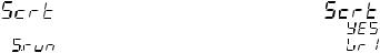
Run time security code
The display will show:
Note: the middle display shows the current status of the run time security code ("0", "1" or "On").
By and push-button, set "S.run" parameter as follows:
0No protection (it is always possible to modify all run time parameters);
1always protected (it is never possible to modify a run time parameter);
from 2 to 250 security code for run time parameter protection.
NOTES:
1)The selected value of a security code cannot be displayed anymore and, coming back to the "S.run" parameter, the display will show "On" when "S.run" is different from 0 or 1, "0" when "S.run" is equal to 0, "1" when "S.run" is equal to 1.
When the security code is forgotten, a new value can be set.
2)When "S.run" is different from 0 or 1, the "run time default " and the "run time hidden" groups are always protected by security code.
Run time groups protected by security code
The display will show:
By this parameter it is possible to set if the run time group 1 will be protected or not by the run time security code.
By and push-button, set "Gr1" parameter as follows:
nO |
No protection (it is always possible to modify run time |
|
group 1 parameters). |
Yes |
the run time group 1 parameter modification will be |
|
protected by security code. |
Push the FUNC push-button; the instrument memorizes the new setting and goes to the next parameter.
NOTES: 1) This selection may be performed only if a run time security code has been set (from 2 to 250).
2)The above described selection may be repeated for all groups of the run time mode.
18
Configuration security code
The display will show:
Note: the middle display shows the current status of the configuration security code ("0", "1" or "On").
By and push-button, set "S.CnF" parameter as follows:
0No protection (it is always possible to modify all configuration parameters);
1always protected (it is never possible to modify a configuration parameter);
from 2 to 250 security code for configuration parameter protection.
NOTES:1) The selected value of a security code cannot be displayed anymore and, coming back to the "S.CnF" parameter, the display will show "On" when "S.CnF" is different from 0 or 1, "0" when "S.CnF" is equal to 0, "1" when "S.CnF" is equal to 1.
When the security code is forgotten, a new value can be set.
2)At the end of the security code setting, set the V101 as described at page16.
RUN TIME AND CONFIGURATION MODES
The hardware selection described in "Operative mode and hardware lock" paragraph allows you to start one of the two following operative modes:
-run time mode
-configuration mode.
At power up, the instrument starts in the same mode it was prior to the power OFF.
General note about graphic symbols used for mnemonic code visualization.
The instrument displays some characters with special symbols. The following table shows the correspondence between the symbols and the characters.
symbol |
character |
|
" |
" |
k |
" |
" |
m |
" |
" |
V |
" |
" |
W |
" |
" |
Z |
" |
" |
J |
19
Keyboard |
description |
|
MENU |
= |
is used to select a parameter group. |
FUNC = |
When the instrument is in "normal display mode" it |
|
|
|
changes the indication on the lower display (see |
|
|
"display function"). |
|
|
During parameter modification, it allows you to |
|
|
memorize the new value of the selected parameter |
|
|
and go to the next parameter (increasing order). |
MAN |
= |
When the instrument is in "normal display mode", |
|
|
pushing MAN push-button for more than 1 s, it is |
|
|
possible to enable or disable the manual function. |
During parameter modification, it allows you to scroll back the parameters and groups without memorizing the new setting.
=During parameter modification, it allows you to increase the value of the selected parameter. During MANUAL mode, it allows you to increase the output value.
=During parameter modification, it allows you to decrease the value of the selected parameter. During MANUAL mode, it allows to decrease the output value.
TST + MAN = By pressing these keys it is possible to start the BURNOFF function.
TST + FUNC = By pressing these keys it is possible to start the PROBE TEST function.
+MENU |
= Are used to start the lamp test function (the |
|
command is accepted when push-buttons are |
|
kept depressed for more than 5 s and the |
|
instrument is in normal display mode) |
+FUNCor |
+FUNC |
|
During parameter modification they allow you to |
|
increase/decrease the value under modification with |
|
higher rate. |
+MAN or |
+MAN |
|
During parameter modification they allow you to |
|
jump to the max or min programmable value. |
20

NOTES:
1)All the actions explained above which requires two or more push-buttons must follow exactly the push-button sequence shown.
2)A 10 or 30 seconds time out (see "CnF.6 - t.out" [C.I08]) can be selected for parameter modification during run time mode. If, during parameter modification, no push-button is depressed for more than 10 (30) seconds, the instrument goes automatically to the “normal display mode” and the modification (if carried out) of the last displayed parameter will be lost.
CONFIGURATION MODE
Switch on the instrument.
The instrument will start in the same way it was prior to the power down (configuration mode or run time mode).
If the instrument starts in configuration mode, push the MENU pushbutton and go to the "Configuration group 1" (see page 25). If the instrument starts in run time mode, by keeping depressed the MENU push-button for more than 5 seconds the instrument will show:
where:
-the upper display shows the selected parameter family;
-the middle display shows the selected action;
-the lower display shows the firmware version.
If no push-button is depressed for more than 10 s (or 30 s according to "CnF.6 - "t.out" [time out selection" C.I08] parameter setting), the instrument automatically returns to the normal display mode.
21

By or push-button it is possible to select between:


 = (monitor) this selection allows you to monitor but not to modify the value assigned to the configuration parameters.


 = (modify) this selection allows you to monitor and to modify the value assigned to the configuration parameters.
NOTES:
1)During monitor mode, the instrument continues to operate as in run time mode.
2)When modify mode is started, the instrument stops the control and:
-sets to OFF the control outputs;
-turns to OFF the bargraph displays;
-sets analog retransmissions to the retransmitted initial scale value;
-sets to OFF the alarms;
-disables the serial link;
-the time out will be disabled.
3) When the modify mode is disabled by V101 (V101.3), the or push-button pressure has no effect.
MONITOR MODE
During the run time mode, it is possible to monitor but not modify all configuration parameters.
When it is desired to verify the instrument configuration, proceed as follows:
1) |
By or push-button select the monitor mode. |
2) |
Push the MENU push-button the display will show: |
it shows that configuration group 1 is selected and it encompasses all the input parameters.
The configuration parameter "Monitor mode" follows the "Modify mode" sequence.
NOTES:
1)During monitor mode, the instrument continues to operate as in run time mode.
2)During monitor mode, if no push-button is depressed for more than 10 s (or 30 s according to "CnF.6 - t.out" [C.I08] parameter setting), the instrument returns automatically to the normal display mode.
22

MODIFY MODE
1) By or push-button select the modify mode.
2)Push the MENU push-button.
If a security code is applied to the configuration parameter, the instrument will show:
3) By and push-button set a value equal to the security code assigned to the configuration mode (see "Configuration security code " at page 19).
If the code is different from the security code, the instrument automatically returns to the first configuration display otherwise the display will show:
The modify mode is started.
This display allows you to load the default configuration parameter (table 1 or table 2).
For more details see chapter "Default parameter" (see Appendix A).
4) By or push-button select the OFF indication and push the MENU push-button.
The display will show:
This is the starting display of the first group of configuration parameters.
NOTES:
1)In the following pages we will describe all the parameters of the instrument but the instrument will show only the parameters related with the specific hardware and in accordance with the specific instrument configuration [i.e. setting OUT 6 as "nonE" (not used), all the parameters related with this output will be automatically skipped].
23

2)During configuration parameters modify mode, the upper display shows the selected parameter group, the lower display shows the mnemonic code of the selected parameter while the central display shows the value or status assigned to the selected parameter.
3)For an easy consultation of this manual, a sheet named "Reference parameter guide" with all the parameter visualizations is enclosed.
The groups of configuration parameters are identified by the "C" letter followed by A, B etc.
The "code" formed by the group and the row (i.e. C.D01 where "C.D" is configuration group1 and "01" is the row 1) is reported, in the user manual, before each parameter description and allows you to quickly find out the respective parameter.
CONFIGURATION GROUP 1 [C.Dxx]
INPUT CONFIGURATION
Push the FUNC push-button
C.D01Line frequency
Upper display: CnF.1 Lower display: Ln.Fr Range: 50 Hz
60 Hz
C.D02Controlled variable selection
Upper display: CnF.1 Lower display: PV.SL Ranges:
CP = Carbon potential (span limits within 0.00% to 2.00%).
dP = Dew point (span limits within -100 to 100 °F or -75 to 40°C). ñV = Sensor output in mV (span limits within 0 to 1500 mV).
O2 = Oxygen value as primary control variable ( The span limits are 0.0 to 25.0)
24
NOTES:
1)Changing the controlled variable, the following parameters: "CnF.6 - brG.L" [C.I03] and "CnF.6 - brG.H" [C.I04] (Bargraph initial and full scale values);
"CnF.2 - O6.Lr" [C.E06] and "CnF.2 - O6.Hr" [C.E07] |
(Out 6 |
retransmission initial and full scale values); |
|
"CnF.2 - O7.Lr" [C.E11] and "CnF.2 - O7.Hr" [C.E12] |
(Out 7 |
retransmission initial and full scale values); |
|
"Gr.5 - rL" [R.E10] and "Gr.5 - rH" [R.E11]
(set point low and high limits); will be forced to the span limits of the new selected variable.
2)SP, SP2, SP3, SP4 values and alarm thresholds, if out of the limits for the new selected variable, will be forced to the low limit value.
C.D03Filter on probe sensor input (Main input)
Upper display: CnF.1 Lower display: Pb.FL
Ranges: from 0 (no filter) to 8 seconds.
NOTES:
1)This is a first order digital filter applied on probe sensor input value.
2)This filter can affect the control action, the alarms, the SMART algorithm and the process variable retransmission.
C.D04 - Temperature input - TC type selection
Upper display: CnF.1 |
|
|
|
|
|
|
Lower display: tP.In |
|
|
|
|
|
|
Ranges: |
|
|
|
|
|
|
1 = TC |
K |
From |
-100 to |
1370 |
°C |
|
2 = TC |
S |
From |
-50 to |
1760 |
°C |
|
3 = TC |
R |
From |
-50 |
to |
1760 |
°C |
4 = TC |
K |
From |
-150 |
to |
2500 |
°F |
5 = TC |
S |
From |
-60 |
to |
3200 |
°F |
6 = TC |
R |
From |
-60 |
to |
3200 |
°F |
7= TC B |
From |
0 to |
1820 |
°C |
||
8= TC B |
From |
32 to |
3300 |
°F |
||
NOTE: When the controlled variable selected is dP, the span limits of the following parameters:
"CnF.6 - brG.L" [C.I03] and "CnF.6 - brG.H" [C.I04] (Bargraph initial and full scale values);
"CnF.2 - O6.Lr" [C.E06] and "CnF.2 - O6.Hr" [C.E07] (Out 6 retransmission initial and full scale values);
"CnF.2 - O7.Lr" [C.E11] and "CnF.2 - O7.Hr" [C.E12] (Out 7 retransmission initial and full scale values);
"Gr.5 - rL" [R.E10] and "Gr.5 - rH" [R.E11]
(set point low and high limits); will be forced to: -100 to 100 °F if the temperature input has been
changed from a °C to a °F type;
-75 to 40 °C if the temperature input has been changed from a °F to a °C type.
25

C.D05 - Temperature input offset adjustment
Upper display: CnF.1 Lower display: OFSt Range: from -500 to 500
NOTE: The offset value is algebraically added to temperature input value.
Read-out Real curve
OFSt  Adjusted
curve
Input
C.D06 - Filter on temperature input value
Upper display: CnF.1 Lower display: tP.FL
Ranges: from 0 (no filter) to 8 seconds.
NOTES:
1)This is a first order digital filter applied to the temperature input value.
2)When "dP" or "CP" or O2 are selected as the controlled variable, this filter can affect the control action, the alarms, the SMART algorithm and the process variable retransmission.
C.D07 - Auxiliary input function
Lower display: |
A.In.F |
|
Range: |
nonE = Input not used |
|
|
CO |
= Input used for CO measurement |
|
rSP |
= Input used as remote set point |
Available: |
Always |
|
Note:The scalable for CO measurement is fixed from 000 to 100 When CO input is not used the CO value will be set to 20
The scalable for rSP measurement is fixed to:
0.00 / 2.00 if carbon potential is selected as primary control variable or
0 /100 °F (-18 / 40 °C) if dew point is selected as primary control variable or 0 / 1500 if sensor output in mV is selected as primary control variable
0.0/ 25.0 if oxygen value is selected as primary control variable
C.D08 - Auxiliary input type selection
Lower display: |
A.In.t |
|
Range: |
0-20 = 0÷20 mA |
|
|
4-20 = 4÷20 mA |
|
|
0- 5 = 0÷ 5 V |
|
|
1- 5 = 1÷ 5 V |
|
|
0-10 |
= 0÷10 V |
|
2-10 |
= 2÷10 V |
Available: |
When auxiliary input is used |
|
26
C.D09 - TIME CONSTANT FOR FILTER ON REMOTE
SETPOINT VALUE |
(CnF.1) |
Lower display: |
A.I.FL |
Range: |
From 0(filter OFF) to 8 s |
Available: |
When auxiliary input is used as remote |
set point |
|
Note: First order filter with selected time constant |
|
C.D10 - REMOTE SETPOINT ACTIVITY MODE (CnF.1) |
|
Lower display: |
A.I.Añ |
Range: |
norñ = The remote set point is |
activated by external contact(or is always activated if none contacts are configured for this feature) and the value is limited at its min/max value when out of range
Cnd.A = The remote set point activation is controlled by status of auxiliary input.
(The device works with local set point when auxiliary input is out of range while it works with remote set point when auxiliary input is in range)
Available: When auxiliary input is used as remote set point
C.D11 - LOCAL / REMOTE SETPOINT OPERATING
MODE (CnF.1)
Lower display: |
L.r.Oñ |
Range: |
ALG = The local setpoint will be |
aligned to last remote setpoint value when transfer from remote to local setpoint action is performed through external contact
n.ALG = The local setpoint will be not be changed when transfer from remote to local setpoint action is performed (The programmed ramp (Grd1/Grd2) may be activated)
Available: When auxiliary input is used as remote set point and (“A.I.Añ = norñ)
Note :If transfer from remote to local setpoint is due to auxiliary input status(“A.I.Añ = Cnd.A) the local setpoint will never been aligned.
27

CONFIGURATION GROUP 2 [C.Exx]
OUTPUTS CONFIGURATION
C.E01 - OUT 1 function
Upper display: CnF.2
Lower display: O1.Fn
Range: nonE |
= Output not used |
ñAin |
= Time proportional main control output |
SECn |
= Time proportional secondary control output |
ALr.1 |
= Alarm 1 output |
C.E02 - OUT 2 function
Upper display: CnF.2
Lower display: O2.Fn
Range: nonE |
= Output not used |
ñAin |
= Time proportional main control output |
SECn |
= Time proportional secondary control output |
ALr.2 |
= Alarm 2 output |
C.E03 - OUT 3 function
Upper display: CnF.2
Lower display: O3.Fn
Range: nonE |
= Output not used |
ñAin |
= Time proportional main control output |
SECn |
= Time proportional secondary control output |
ALr.3 |
= Alarm 3 output |
C.E04 - OUT 6 function
Upper display: CnF.2
Lower display: O6.Fn
Range: nonE |
= Output not used |
ñAin |
= Main control output (linear) |
SECn |
= Secondary control output (linear) |
PV.rt |
= Process variable retransmission |
SP.rt |
= Operative set point retransmission |
C.E05 - OUT 6 range
This parameter is available only when OUT 6 ("O6.Fn" [C.E04]) is different from "nonE".
Upper display: CnF.2 Lower display: O6.rn
Range: 0-20 |
= 0-20 mA |
4-20 |
= 4-20 mA |
28
 Loading...