

Page 1

SuperData
Software
OPERATIONS MANUAL
COPYRIGHT
No part of this publication may be reproduced, transmitted, transcribed, stored in a retrieval system, or translated into any language or computer
language, in any form or by any means, electronic, mechanical, magnetic, optical, chemical, manual, or otherwise, without prior written permission
of Super Systems Inc., 7205 Edington Dr., Cincinnati, OH 45249 USA.
SuperData is a suite of software programs to be used by the Heat Treater. Super Systems Inc. is not responsible or liable for any product, process,
or damage or injury incurred as a result of using SuperData. Super Systems Inc. makes no representations or warranties with respect to the
contents hereof and specifically disclaims any implied warranties or merchantability or fitness for any particular purpose.
DISCLAIMER
Super Systems Inc.
7205 Edington Drive
Cincinnati, OH 45249
513-772-0060 / 800-666-4330
Fax: 513-772-9466
www.supersystems.com
Super Systems Inc Page 1 of 172 Super Data Operations Manual
Page 2

Table Of Contents
TABLE OF CONTENTS ........................................................................................................................................ 2
SUPERDATA COMMUNICATIONS .................................................................. 8
SDIO INTRODUCTION ...................................................................................................................................... 8
STARTING SDIO ............................................................................................................................................. 8
MENU OPTIONS .............................................................................................................................................. 9
Action Menu ............................................................................................................................................ 9
Settings Menu. ......................................................................................................................................... 9
View Menu .............................................................................................................................................. 9
Comms View ................................................................................................................................................................. 10
Status View ................................................................................................................................................................... 11
Chan Data View ............................................................................................................................................................ 12
Help Menu ............................................................................................................................................. 13
SDIO INSTALLATION ...................................................................................................................................... 14
SDIO CONFIGURATION ................................................................................................................................... 18
Overview ............................................................................................................................................... 18
Protocols ............................................................................................................................................... 18
Instrument Types ................................................................................................................................... 19
Overview ...................................................................................................................................................................... 19
System Instruments ...................................................................................................................................................... 19
System Channels ....................................................................................................................................................... 19
Physical Instruments ..................................................................................................................................................... 19
Super Systems Instruments ....................................................................................................................................... 19
Eurotherm Instruments ............................................................................................................................................. 19
Honeywell Instruments ............................................................................................................................................ 20
Yokogawa Instruments .............................................................................................................................................. 20
Marathon Instruments ............................................................................................................................................... 21
Other Instruments .................................................................................................................................................... 22
TypeID Reference ......................................................................................................................................................... 22
Configuration File .......................................................................................................................................................... 23
RES Section .............................................................................................................................................................. 23
CONx Section ............................................................................................................................................................ 24
Instrument Section.................................................................................................................................................... 25
System Channels ............................................................................................................................................................................. 25
Super Systems Instruments .............................................................................................................................................................. 26
Generic MODBUS Instruments ....................................................................................................................................................... 27
MMI 10Pro and Barber Coleman 560 Instrument ........................................................................................................................... 28
MMI V3 and V3.5 Instruments ....................................................................................................................................................... 29
MMI V4 Instruments ....................................................................................................................................................................... 30
MMI CARB-PC Instruments ........................................................................................................................................................... 32
Honeywell CPL Instruments ........................................................................................................................................................... 32
Honeywell MODBUS Instruments .................................................................................................................................................. 33
Honeywell DPR3000 Instruments ................................................................................................................................................... 35
Yokogawa CPL Instruments ............................................................................................................................................................ 36
AllenBradley DF1 Instruments ........................................................................................................................................................ 37
Eurotherm Controllers ..................................................................................................................................................................... 38
Sample SCSPSYS.CFG File ......................................................................................................................................... 39
Alarm Block Configuration.............................................................................................................................................. 42
COMMUNICATIONS UTILITIES ............................................................................................................................ 44
Utilities .................................................................................................................................................. 44
SDCommSrv .......................................................................................................................................... 44
Super Systems Inc Page 2 of 172 Super Data Operations Manual
Page 3

ChStat ................................................................................................................................................... 44
SDIOConfig ............................................................................................................................................ 45
SDIOConfig Main Screen................................................................................................................................................ 47
SDIOConfig Connection Dialog ....................................................................................................................................... 48
SDIOConfig Instrument Configuration ............................................................................................................................ 48
ComRBridge ........................................................................................................................................... 50
ComRBridgeSrv ...................................................................................................................................... 53
Krunch .................................................................................................................................................. 53
CompDT ................................................................................................................................................ 54
ComSlots ............................................................................................................................................... 54
GetBuff ................................................................................................................................................. 55
PutBuff .................................................................................................................................................. 55
RWI ...................................................................................................................................................... 56
GetData ................................................................................................................................................ 56
GetStats ................................................................................................................................................ 57
SUPERDATA OPC COMMUNICATIONS ........................................................ 58
OPCBRIDGE ................................................................................................................................................ 58
OPCBridge Graphical Enviornment ............................................................................................................ 58
Starting OPCBridge ................................................................................................................................. 58
Menu Options ........................................................................................................................................ 58
File Menu. ..................................................................................................................................................................... 58
Chanel Menu. ................................................................................................................................................................ 58
OPC .............................................................................................................................................................................. 59
View ............................................................................................................................................................................. 59
Help .............................................................................................................................................................................. 60
SDOPC Installation ................................................................................................................................. 60
OPCBridgeSrv.exe................................................................................................................................... 65
OPCBridge Configuration ......................................................................................................................... 66
SUPERDATA DISPLAY AND INTERACTION ................................................. 71
REALEDIT.EXE .............................................................................................................................................. 71
RealEdit Graphical Environment ............................................................................................................... 71
Menus ........................................................................................................................................................................... 71
File ........................................................................................................................................................................... 71
Edit .......................................................................................................................................................................... 71
View ......................................................................................................................................................................... 72
Options ..................................................................................................................................................................... 72
Window .................................................................................................................................................................... 73
Help ......................................................................................................................................................................... 73
Toolbar ......................................................................................................................................................................... 74
Coolbar ......................................................................................................................................................................... 74
REALEDIT COMMON FORMS .............................................................................................................................. 74
Property Edit Sheet ................................................................................................................................. 74
Colors: .......................................................................................................................................................................... 75
Size and Position: .......................................................................................................................................................... 75
Lists:............................................................................................................................................................................. 75
Combo Box: .................................................................................................................................................................. 75
Color Dialog ........................................................................................................................................... 76
Caveats with the Color Dialog .................................................................................................................. 77
List Builder ............................................................................................................................................ 77
ODBC Edit Wizard ................................................................................................................................... 78
RealEdit Settings .................................................................................................................................... 79
Scale Factor ........................................................................................................................................... 80
REALEDIT OBJECTS ........................................................................................................................................ 81
Super Systems Inc Page 3 of 172 Super Data Operations Manual
Page 4

Communications ..................................................................................................................................... 82
Communications Channel Definitions.............................................................................................................................. 82
Properties ................................................................................................................................................................. 82
Communications Channel Source Parameter................................................................................................................... 82
Properties ................................................................................................................................................................. 82
Communications Channel Destination Parameter ............................................................................................................ 82
Properties ................................................................................................................................................................. 82
Fonts .................................................................................................................................................... 84
Constants .............................................................................................................................................. 86
Data Processes....................................................................................................................................... 86
Data Values ........................................................................................................................................... 88
Data Value Lists ..................................................................................................................................... 90
ODBC Connections.................................................................................................................................. 92
Pointers ................................................................................................................................................. 93
Trend Lines ........................................................................................................................................... 94
File References....................................................................................................................................... 96
Picture File References .................................................................................................................................................. 96
Application File References ............................................................................................................................................ 96
INI File References ........................................................................................................................................................ 96
Flat ASCII File References ............................................................................................................................................. 97
Link Screen File References ........................................................................................................................................... 98
Crystal Report File References ....................................................................................................................................... 98
Datalog File References ................................................................................................................................................. 98
Data Socket Sources ............................................................................................................................... 99
Data Socket Destinations ....................................................................................................................... 100
Function Sources .................................................................................................................................. 101
Image Boxes ........................................................................................................................................ 102
Simple Shapes ..................................................................................................................................... 103
Logic Boxes ......................................................................................................................................... 104
Portable Images ................................................................................................................................... 105
Simple Labels ....................................................................................................................................... 106
Auto Labels.......................................................................................................................................... 107
Edit Boxes ........................................................................................................................................... 108
Lookup Lists ........................................................................................................................................ 109
Spin Buttons ........................................................................................................................................ 110
Meters ................................................................................................................................................ 111
Simple Scales ....................................................................................................................................... 112
Recipe Boxes ....................................................................................................................................... 113
Alarm Lists .......................................................................................................................................... 114
Link Screen Buttons .............................................................................................................................. 116
RealTime Event Buttons ........................................................................................................................ 117
Data Grids ........................................................................................................................................... 118
Graphs ................................................................................................................................................ 118
Historical Graphs .................................................................................................................................. 120
Dials ................................................................................................................................................... 123
Toggle Buttons ..................................................................................................................................... 124
Numeric Edits ...................................................................................................................................... 127
Date Pickers ........................................................................................................................................ 127
iTools .................................................................................................................................................. 129
Animations .......................................................................................................................................... 130
Event Lists ........................................................................................................................................... 130
REALTIME EVENTS ....................................................................................................................................... 132
Copy Data Value X to Destination. .......................................................................................................... 132
Copy Pending Edit of Data Value X to Destination..................................................................................... 132
Append Blank Record. ........................................................................................................................... 132
Super Systems Inc Page 4 of 172 Super Data Operations Manual
Page 5

Show Hourglass Mouse Cursor. .............................................................................................................. 132
Clear Hourglass Mouse Cursor. ............................................................................................................... 132
Delete Database Record. ....................................................................................................................... 132
Send Pending Edit. ............................................................................................................................... 132
Cancel All Pending Edits. ....................................................................................................................... 133
Discard Current Screen. ........................................................................................................................ 133
Show Message with No Buttons. ............................................................................................................ 133
Show Message with Abort Button Only. ................................................................................................... 133
Show Message with Continue Button Only. .............................................................................................. 133
Show Message with Abort and Continue Buttons. ..................................................................................... 133
Wait For Continue Button. ..................................................................................................................... 133
Wait For Data Value X = Data Value Y. ................................................................................................... 133
Hide a Message. ................................................................................................................................... 134
Refresh All Files. ................................................................................................................................... 134
Reload All Lookup List. .......................................................................................................................... 134
Unconditional Screen Update. ................................................................................................................ 134
Discard All Other Screens. ..................................................................................................................... 134
Abort Button Branch Point. .................................................................................................................... 134
Append and Copy Value List to Destination. ............................................................................................. 134
Copy Value List to Destination. ............................................................................................................... 135
End RealTime....................................................................................................................................... 135
Exit Event if Data Value X = Data Value Y. .............................................................................................. 135
Update All Edit Boxes on the Screen. ...................................................................................................... 135
Clear Database Fields for Current Record. ............................................................................................... 135
Send a Report to the Screen. ................................................................................................................. 135
Send a Report to The Printer. ................................................................................................................ 135
Run an External Application File. ............................................................................................................ 135
End RealTime and Run an External Application File. ................................................................................. 136
Start New Screen. ................................................................................................................................ 136
Start v3.5 Recipe Program. .................................................................................................................... 136
Stop v3.5 Recipe Program. .................................................................................................................... 136
Search Datalog Data. ............................................................................................................................ 136
Erase a Destination File. ........................................................................................................................ 136
Print Current RealTime Screen. .............................................................................................................. 136
Minimize Current RealTime Screen. ........................................................................................................ 136
Maximize Current RealTime Screen. ........................................................................................................ 137
Normal Size Current RealTime Screen. .................................................................................................... 137
Set a Bit (Data Value X) in Destination. ................................................................................................... 137
Reset a Bit (Data Value X) in Destination. ................................................................................................ 137
Toggle a Bit (Data Value X) in Destination. .............................................................................................. 137
Refresh ODBC Specified in Destination. ................................................................................................... 137
Copy Data Value X to Pending Edit Value. ............................................................................................... 137
Move to First Record. ............................................................................................................................ 137
Move to Previous Record. ...................................................................................................................... 138
Move to Next Record. ........................................................................................................................... 138
Move to Last Record. ............................................................................................................................ 138
Copy pending edit value X to Destination ................................................................................................ 138
Append Value List to ODBC Destination as New Record............................................................................. 138
Exit to abort branch point if Data value X =Data Value Y .......................................................................... 138
Exit RTEvents....................................................................................................................................... 138
Jump to next Abort branch point ............................................................................................................ 138
Do while (data value X)<=(data value Y) ................................................................................................ 139
While end (must follow Do While Event) ................................................................................................. 139
Super Systems Inc Page 5 of 172 Super Data Operations Manual
Page 6

For 1 to (Data value X) ......................................................................................................................... 139
Next (must follow for loop) .................................................................................................................... 139
Suspend Execution for X milliseconds...................................................................................................... 139
Enable/Disable Screen Object ................................................................................................................ 139
Start SSI Recipe ................................................................................................................................... 139
Stop SSI Recipe ................................................................................................................................... 140
Hold SSI Recipe ................................................................................................................................... 140
Resume SSI Recipe ............................................................................................................................... 140
Advance SSI Recipe .............................................................................................................................. 140
Edit SSI Recipe .................................................................................................................................... 140
Run Edited SSI Recipe .......................................................................................................................... 140
Cancel SSI Recipe................................................................................................................................. 141
SUPERDATA RECORDER ........................................................................... 142
OVERVIEW ................................................................................................................................................ 142
DISPLAY ................................................................................................................................................... 143
Components of SDRecorder Display ........................................................................................................ 143
CHART VIEW .............................................................................................................................................. 144
CURSOR DATA AREA ..................................................................................................................................... 145
CHART CONTROL AREA ................................................................................................................................. 146
MENUS ..................................................................................................................................................... 148
File Menu ............................................................................................................................................ 148
Export Menu ........................................................................................................................................ 148
Points Menu ......................................................................................................................................... 148
Options Menu ...................................................................................................................................... 148
View Menu .......................................................................................................................................... 149
Loads Menu ......................................................................................................................................... 149
Notes Menu ......................................................................................................................................... 149
Help Menu ........................................................................................................................................... 149
TOOLBAR .................................................................................................................................................. 150
HOW TO ................................................................................................................................................... 151
Open a Chart ....................................................................................................................................... 151
Create a Chart ..................................................................................................................................... 151
Add a Chart Pen ................................................................................................................................... 151
Edit a Chart Pen ................................................................................................................................... 152
Delete a Chart Pen ............................................................................................................................... 153
Select a Process Scale ........................................................................................................................... 153
Set Chart Times ................................................................................................................................... 154
Use the Cursor ..................................................................................................................................... 155
Zoom .................................................................................................................................................. 156
Pan ..................................................................................................................................................... 157
Hide a Pen ........................................................................................................................................... 157
View a Pen's Statistics ........................................................................................................................... 158
Print a Chart ........................................................................................................................................ 160
View the Data Grid ............................................................................................................................... 161
Historical Load Chart ............................................................................................................................. 162
View an Alarm Report ........................................................................................................................... 164
Use Notes ............................................................................................................................................ 164
Viewing Notes .............................................................................................................................................................. 165
Adding Notes ............................................................................................................................................................... 167
FILES AND CONFIGURATION ............................................................................................................................ 168
SDRec Files .......................................................................................................................................... 168
SDRec Configuration ............................................................................................................................. 168
Super Systems Inc Page 6 of 172 Super Data Operations Manual
Page 7

Command Line ..................................................................................................................................... 171
Alternate Command Line: ............................................................................................................................................. 171
REVISION HISTORY ...................................................................................................................................... 172
Super Systems Inc Page 7 of 172 Super Data Operations Manual
Page 8

SuperData Communications
(SDIO.exe)
SDIO Introduction
The SuperData Comms application (SDIO.exe) is the communications program that provides up to 127 channels of
serial communications to configured instruments and builds shared data tables for other applications to access
instrument data. The communications program supports up to 8 serial ports and 120 Ethernet/TCP ports. Each port
may be configured with a different serial protocol (e.g. MMI, Modbus, CPL, DF1, etc.). This provides the flexibility to
connect to a wide variety of industrial controllers.
The following functions are provided by the SuperData Communications application:
1. Automatic polling for configured instruments.
2. Shared data tables for other applications to access instrument data.
3. Automatic data logging of all configured instruments on a minute-by-minute basis.
4. Real Time updates of process data.
5. Message handling system to allow other applications to read and write to configured instruments.
6. Provide communications statistics.
7. Provide communications error handling.
8. Periodic compression of logged data.
9. Provides an application event log for communications error and warning messages. The event log may be
viewed using the Windows event log viewer.
Starting SDIO
SDIO must be configured prior to running the application. Configuration consists of defining:
• File locations
• Serial Ports
• Instrument types, addresses and polling
Configuration is normally accomplished by Service personnel when SuperData is installed. The
section contains details on how to configure SDIO.
SDIO.exe is normally located in the \SSI\BIN directory and may be started manually from the directory by clicking on
the application file. However, SDIO is designed to run all of the time (24/7) and is normally started as a service.
When SDIO is run as a service, it will start automatically any time the computer is turned on (logon is not required).
To setup SDIO as a service, see the section
When SDIO is running, you will see the SDIO icon in the Quick Launch Toolbar portion of the Taskbar (normally on
the lower right portion of the desktop). When communications are normal, the dot above the "i" in the icon will blink
rapidly. Clicking the icon will bring the SDIO window to the foreground. Only one instance of SDIO is allowed to run
on a computer.
SDCommSrv
in the
Communications Utilities
section.
SDIO Configuration
Super Systems Inc Page 8 of 172 Super Data Operations Manual
Page 9
Menu Options
The following menu options are available on the
SuperData Communications
menu bar:
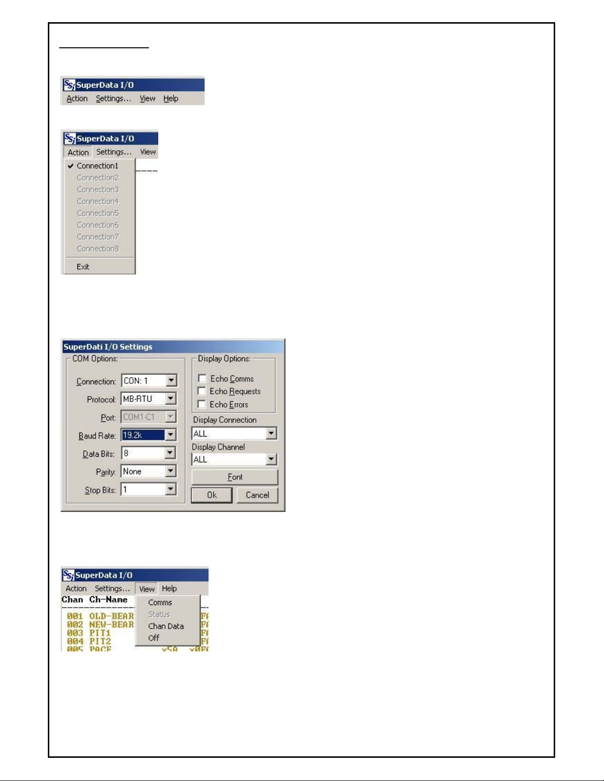
Action Menu
The Action menu dropdown shows the 8 serial connections. Configured connections are
in normal text. Connections that are not configured are shown in dimmed text. Clicking
on a connection will toggle between connect and disconnect. This is a useful tool to
reinitialize the communications port without having to shutdown and restart SDIO. A
connection with a checkmark is connected. A disconnected connection will only remain
disconnected for a max of 30 minutes. This is useful to re-initialize the communications
port without having to shut down and restart SDIO.
The Exit menu item stops the communications program.
Settings Menu.
The Settings menu item displays the following Settings dialog box:
The COM Options section of this dialog is used to view or
set the communications options for each connection.
Setting the communications options with this dialog is
temporary
revert to the settings in the configuration file
(SCSPSYS.CFG). To make settings
change the configuration file. To make temporary
communications changes, the associated connection must
first be disconnected. The PORT dropdown will display the
connection assigned to the port.
The Display options section is used to set the
information is to be displayed in the Comm view. The
Display Connection and Display Channel dropdowns
select which connections and channels are to be displayed
in the Comm. View. The Display Channel selection is
used to set the channel to view data in the Chan Data
view.
The Font button is used to open the Font selector dialog.
View Menu
The View Menu is used to select the Comms, Status or Chan Data view.
This menu may also be used to turn the view off. When the view is turned
off, the display will stop updating until the comm. or Status view is selected.
The Comms view displays messages and errors for selected channels as
configured in settings.
The status view displays an overall status of the communications.
The Chan Data view displays the polled data received from the instrument.
SDIO will normally be in the Status view.
. When the program restarts, the settings will
permanent
, you must
Super Systems Inc Page 9 of 172 Super Data Operations Manual
Page 10
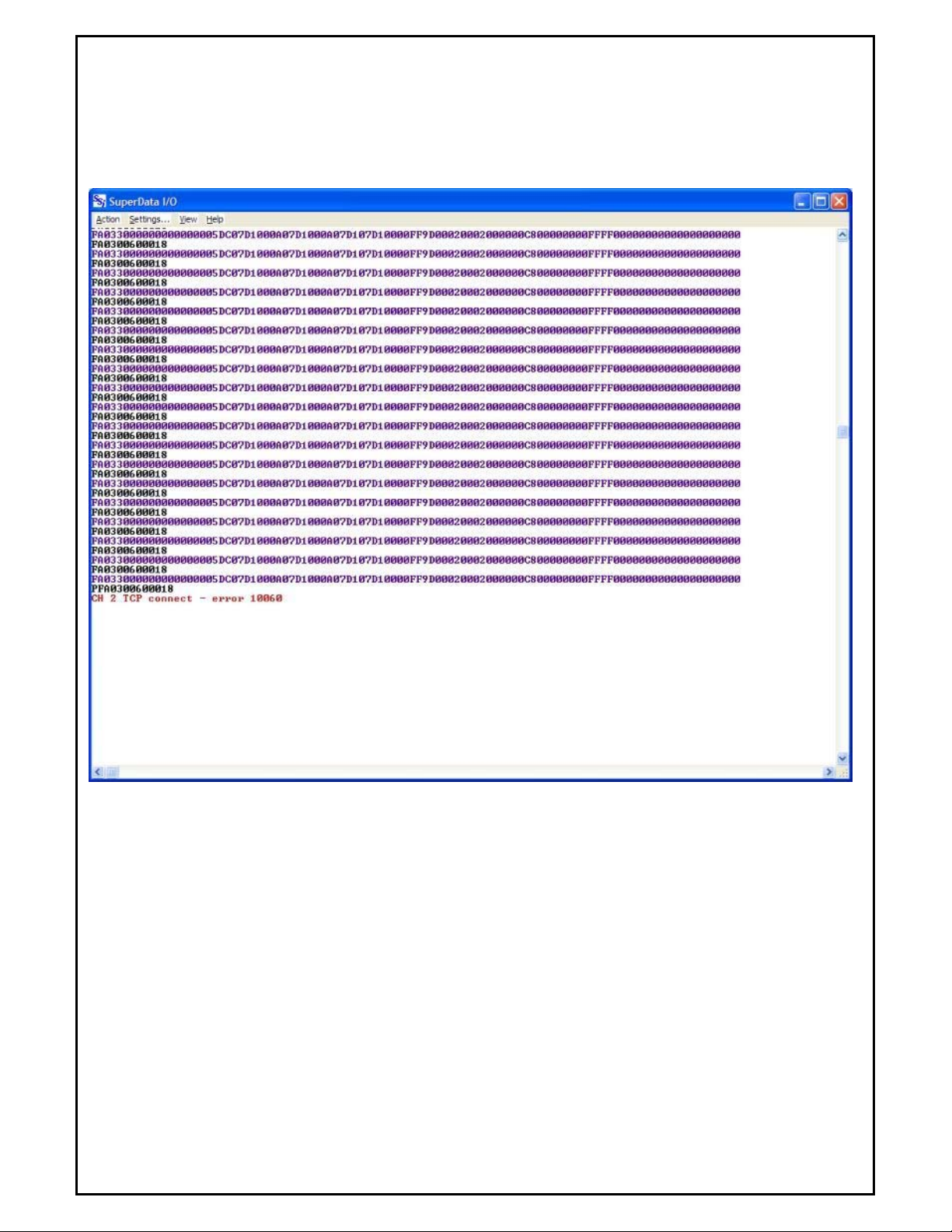
Comms View
The Comms view is normally used for trouble-shooting communications. Leaving the comm view open can slow
down communications throughput so it is best to return to the status view when not using the comms view.
Transmitted messages from the Comms program are displayed in BLACK, responses from the instrument are
displayed in PURPLE, and errors are displayed in RED. The screen scrolls as messages are transmitted and received.
To stop scrolling, use the "View Off" menu.
Super Systems Inc Page 10 of 172 Super Data Operations Manual
Page 11

Status View
There will be one line for each configured instrument. Normally communicating instruments will be displayed in
BLACK, disconnected instruments will be displayed in dimmed text (GREY), invalid instruments (instruments that are
incompatible with the connection protocol) are displayed in RED, and instruments with errors (i.e. valid but not
communicating) are displayed in dark YELLOW
The following columns are displayed for each channel:
Chan – the logical channel number (1-127)
Ch-Name – the channel's name (up to 11 characters)
TYP – the channel's type identifier followed by L (logged channel) or N (not logged).
PC – the physical channel (in HEX). The first hex character is the connection (0-7 for serial connections 1-8; 8
– 127 for TCP connections), the remaining 2 hex characters identify the instrument's physical address.
TBL – an optional Table identifier.
PP – the current polling priority (1-3). If communications are good, polling priority will be 1. When the
instrument has 10 or more consecutive errors, polling priority will be set to 2 and the SDIO will only try to
reconnect to the instrument every 30 secs, when the consecutive error count exceeds 20 errors, priority will be
set to 3 and communications will attempt to reconnect every 2 minutes.
EC – the current consecutive error count.
Super Systems Inc Page 11 of 172 Super Data Operations Manual
Page 12
CPS – the estimated communications throughput in characters per second.
EPH – the estimated error rate in errors per hour.
UTI – the estimated update time interval in seconds (time between complete updates for the instrument).
COMM STATUS – identifies the instruments Station, Connection ID and current status. In most configurations
the Station will be zero.
CTR – update counter, counts the number of times the channel has been updated (rolls over at 9999 counts.)
Note
- System Channels (maintained by other applications) are a special case. SDIO does not know
their communications status. They will always contain the following column values
:
TYP - x14
PC – x000
TBL – x00
PP – 01
EC – 00
CPS – 001
EPH – 000
UTI – 999.9
COMM STATUS – SC01-OK
CTR – 0001
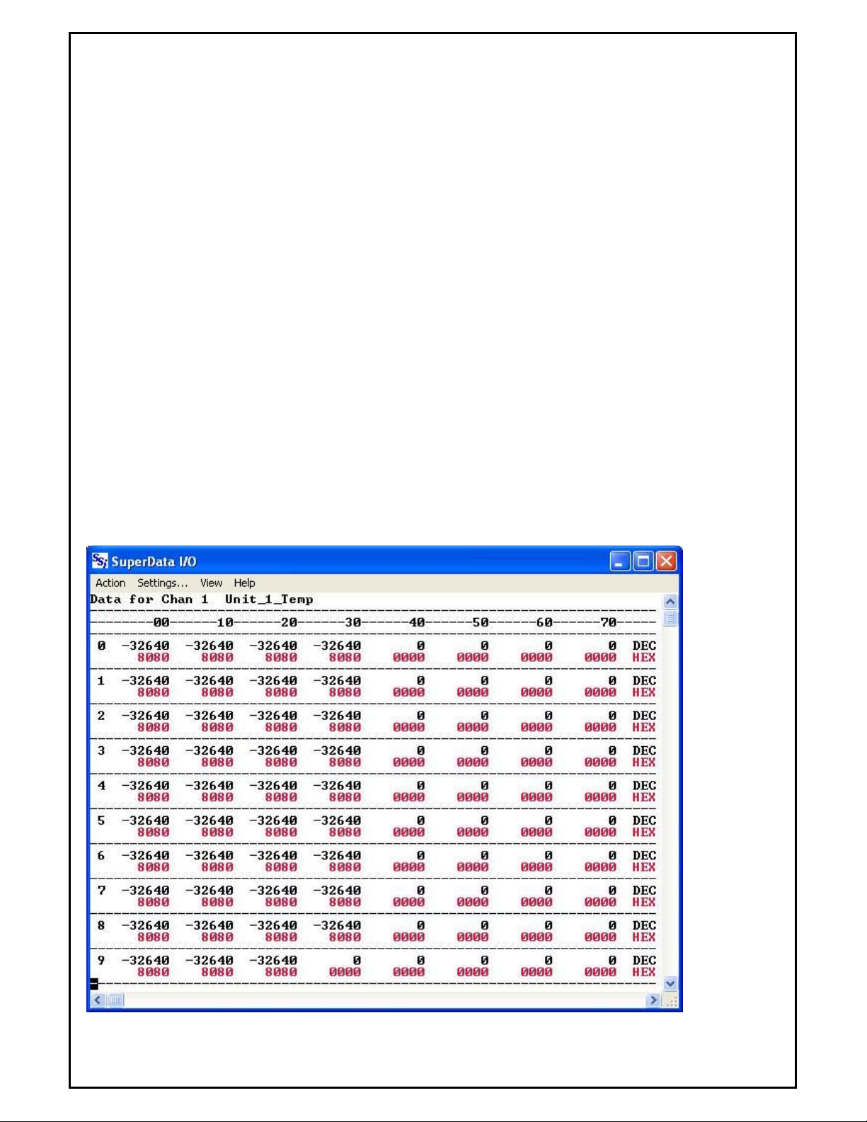
Chan Data View
This table displays the current value of all 80 slots of the Channel selected in the Settings Menu.
Super Systems Inc Page 12 of 172 Super Data Operations Manual
Page 13

The values displayed in black are decimal while the ones in red are in hexadecimal format.
are reserved for use by SDIO
. Slot 78 is used for CPS, and slot 79 is used for special alarm purposes (ABC
Note – Slots 78 and 79
configuration).
Help Menu
The Help Menu provides options to display the help file or to display the SuperData Communications about box.
Super Systems Inc Page 13 of 172 Super Data Operations Manual
Page 14
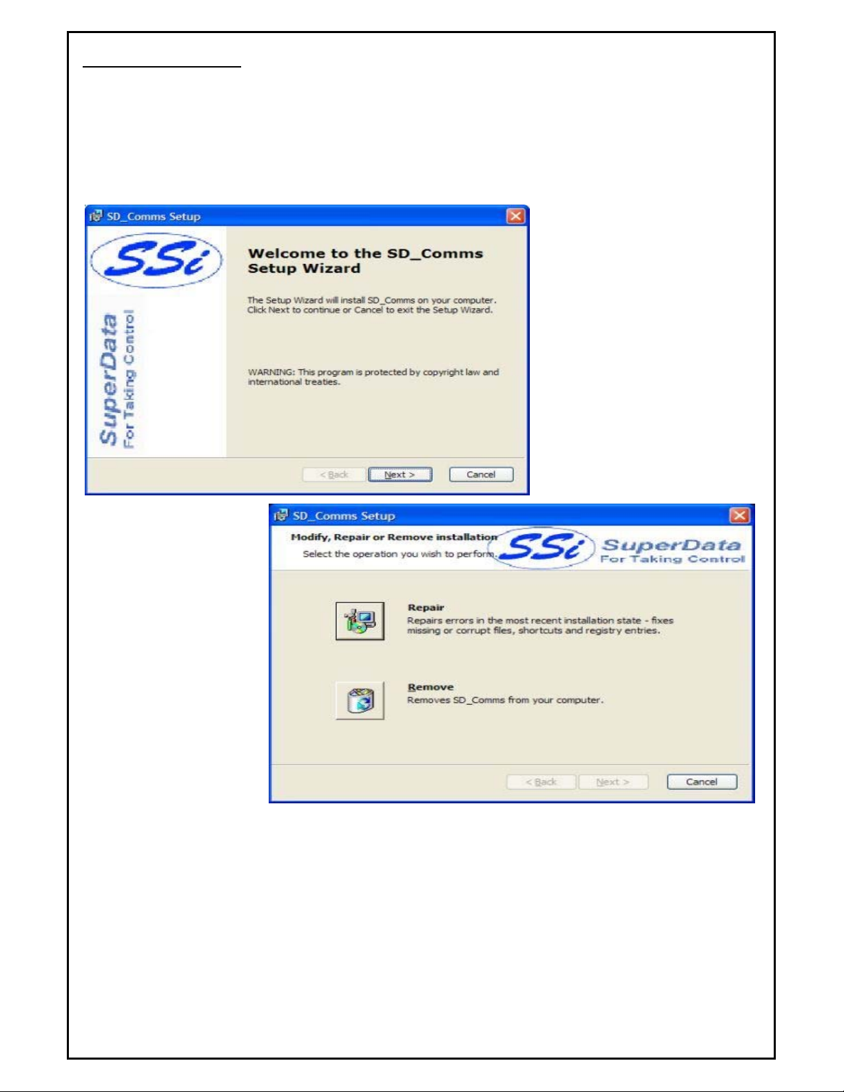
SDIO Installation
Note – The person installing the SD_Comms Software must have administrative rights on the
computer(s) where the installation is taking place for the installation to be successful
Insert the SuperData Installation CD into the computer’s optical drive and navigate to the SuperData folder. Doubleclick on the setup file - SDComms_Setup.msi - to start the auto-installation. If there is no version of the SD_Comms
running on the computer, the installation will display a splash screen.
Clicking the Next > button will
continue with the installation process.
Clicking on the Cancel button will
cancel the installation process. The
user will have to confirm the
cancellation.
.
If there is a version of the
SD_Comms already installed
on the computer, The
following screen will be
displayed:
The installer will either reinstall the software (Repair
button) or remove the
software from the computer
(Remove button). Clicking
on the Cancel button will
cancel the actions. The user
will have to confirm the
cancellation.
Note - the
installer does not
remove any subfolders in the main SSI folder. These files will have to be manually removed
. The
Repair option will allow the user to repair the installed files. This option is useful if the installation was interrupted in
some way and did not finish on its own.
The Remove option will remove the main executable file from the computer.
Super Systems Inc Page 14 of 172 Super Data Operations Manual
Page 15
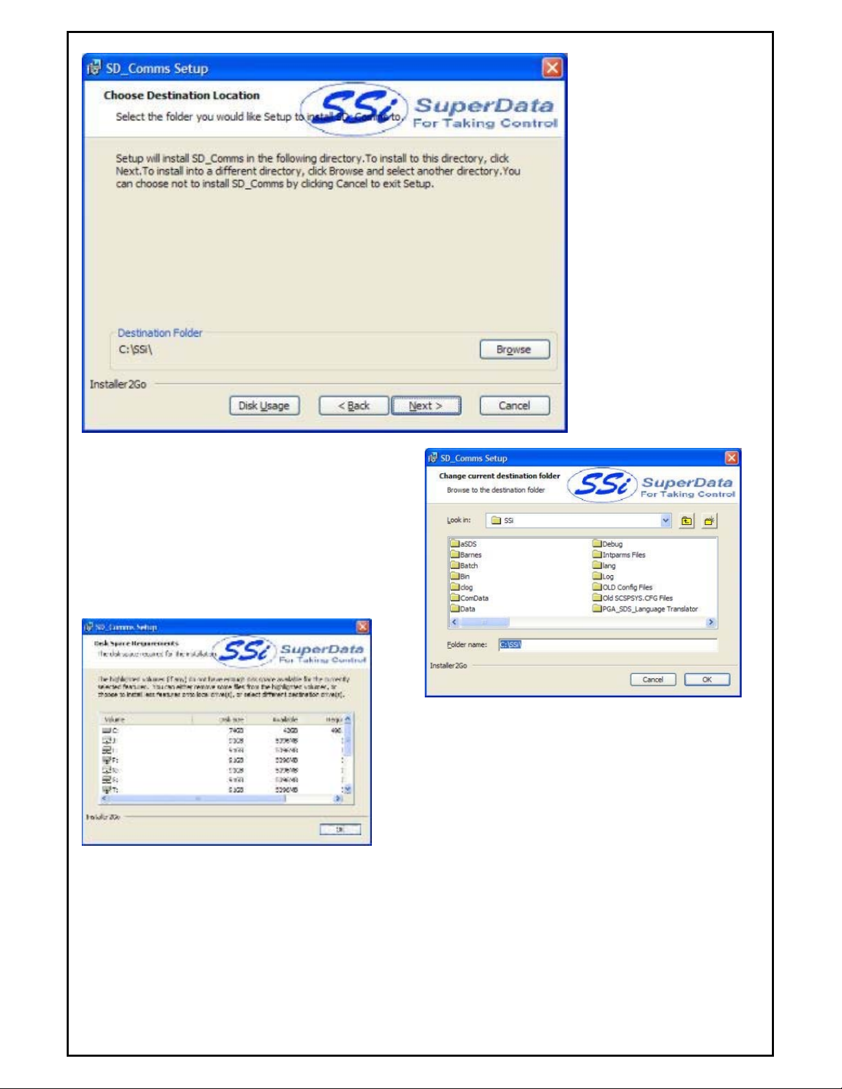
The next screen will prompt
the user for the download
location. The default location
is “C:\SSI\”.
Note: The
installer will automatically
create a “Bin” folder to install
the files to. For example, if
the default location, “C:\SSi\”
is used, then the files will be
installed to “C:\SSi\Bin”.
The user can click on the Browse button to select an
alternate location (right).
Clicking on the Disk Usage button will display the
available computer drives onto which the application can
be downloaded, as well as the total space, available
space and total space required (below). Clicking on the
OK button will close out the disk usage screen.
Clicking on the < Back button will display the previous screen.
Clicking the Next > button will continue with the installation
process.
Clicking on the Cancel button will cancel the installation process. The user will have to confirm the cancellation.
Super Systems Inc Page 15 of 172 Super Data Operations Manual
Page 16
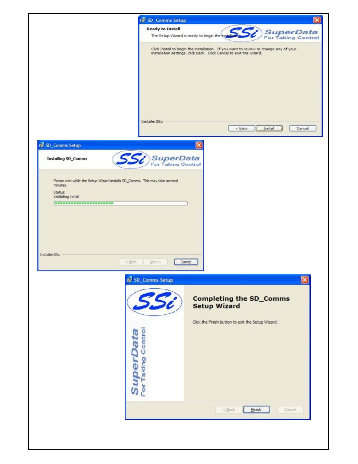
Clicking on the Cancel button will
cancel the installation process. The user
will have to confirm the cancellation.
Clicking on the < Back button will
display the previous page.
Clicking on the Install button will
install the software to the specified
location.
Click Finish to complete the
installation process.
Super Systems Inc Page 16 of 172 Super Data Operations Manual
Page 17

SD_Comms Minimum System Requirements
• Computer with a minimum of 600 MHz processor clock speed (Intel, AMD, etc).
• Operating System – Microsoft Windows 98/2000/XP/Vista
• Memory – 256 MB RAM or higher
• Disk Space - Minimum of 1 GB storage space
• CD-ROM drive or DVD-ROM drive
• Keyboard and mouse
• Monitor with 1024 x 768 resolution or higher and 256 colors
Super Systems Inc Page 17 of 172 Super Data Operations Manual
Page 18

SDIO Configuration
Overview
SuperData Comms Configuration File (SCSPSYS.CFG)
SuperData Comms is configured using a configuration file called SCSPSYS.CFG. This file is normally found in the
C:\SSi directory and may be edited using the configuration tool SDIOConfig.exe, (see Page 45), or any text editor
(e.g. Notepad, WordPad, TextPad, etc). When editing this file, always save this file as an ASCII text file. Anytime
the file is modified SuperData Comms will automatically reconfigure – there is no need to stop and restart SuperData
Comms (SDIO).
The configuration file consists the following sections:
RES– the basic communications parameters.
CONx– the communications configuration for each connection used (up to 8 sections)
INST – the instrument configuration parameters
ABC– optional section containing custom Alarm Block Configurations
Protocols
The following protocols are currently supported by SDIO:
MB-RTU Protocol is used for any instrument capable of Modbus RTU comms. This protocol is a binary protocol.
Modbus is capable of using integer or floating point data; However, SDIO converts all floating point data to integer
data for data logging and display. Modbus instruments may be connected using either RS485 2-wire or RS485 4wire. A wide variety of control instruments now use Modbus RTU comms including: Super Systems, Eurotherm,
Honeywell, Yokogawa etc.
ModbusTCP This protocol is Modbus over Ethernet used for any instrument capable of ModbusTCP or may be used
on Modbus RTU instruments with the addition of a Ethernet to Serial converter. Super Systems 9000 series
instruments directly support ModbusTCP.
HW-CPL Protocol is used with the Honeywell DCP550 controller. This protocol is a variation of PC Link. Data is
transmitted as a mix of binary and ASCII values. Instruments may be connected using either RS485 2-wire or
RS485 4-wire.
MMI-MSI Protocol is used for all Marathon Instruments. This protocol is an ASCII protocol and always uses 7 data
bits, EVEN parity and 1 stop bit. Baud rates depend on the instrument type. This is the only protocol that can be
used with the Marathon COMMUX board. Data is transmitted by WORDS (16 bit integers) or BLOCKs of 24 WORDS.
Instruments are always connected using RS485 2-wire. Note: SuperS ystems does not recommend using the
Marathon COMMUX board - it is no longer in production and no longer supported by Marathon Sensors.
YOK-CPL Protocol is used with Yokogawa UT series controllers. This protocol is a variation of PC Link. Data is
transmitted as a mix of binary and ASCII values. Instruments may be connected using either RS485 2-wire or
RS485 4-wire. Note: Most Yokogawa instruments now support Modbus RTU protocol and Modbus is the preferred
method of communications to those instruments.
AB-DF1 Protocol is used with AllenBradley PLC controllers. Typically, these controllers use RS232 ports. For long
distance, multidrop connections, each controller will require an RS232 to RS485 converter. Note: SDIO supports only
a limited subset of the DF1 protocol. The preferred method of talking to Allen Bradley PLCs is RSLinx (an OPC
Server) with Super Data's OPCBridge.
Note - If the instrument in use does not support one of the above protocols, SuperData may still
communicate with the instrument if there is an OPC Server available
supports numerous control instruments. If an OPC Server is available - Super Data's OPCBridge - see the
section to learn how to map data from the OPC Server to SDIO. This allows SuperData to communicate with nearly
all instruments used in the Heat Treat Industry.
. Software Toolbox's TOPServer
OPCBridge
Super Systems Inc Page 18 of 172 Super Data Operations Manual
Page 19

Instrument Types
Overview
Supported Instrument Types
SuperData Communications supports a variety of control instruments used in the Heat Treating industry. In the
following sections, the instrument ID (indicated in CAPS) is used to identify the instrument in the SCSPSYS.CFG file.
The instrument type code (numeric) follows each ID and is displayed in decimal and Hex. The Hex value is
displayed as the type on the SDIO status display and the ChStat display. Instruments that are not specifically
supported, may be supported by using an OPC Server in conjunction with SuperData's OPCBridge.
System Instruments
System Channels
SYS
System channels are SDIO channels that are maintained by an external application. SDIO does not provide
direct communications with these instruments. SDIO does log the data in these channels and makes the data
available for trending and screen display applications.
Examples of System channels:
OPCBridge channels
ComRBridge channels
Load Tracking applications
Dummy channels used for test/development
Physical Instruments
Super Systems Instruments
Super Systems Controllers
SSI_CON
MOD_SMPP
MOD_SSI
SSI-9000
SSI-9200
SSI-9205
SSI-9205V2
SSI-9210
SSI-9220
Note - For the 9000 Series instruments Slots 0 through 25 are predefined. Specific Modbus
blocks can be added starting at Slot 26
Generic MODBUS Instruments
MOD_PMC note 1
MMI_MOD note 2
Note 1. This protocol uses Modbus FN 03 to read registers and FN 6 or FN 16 to write registers. Values to
be polled are specified in the instrument configuration line.
Note 2. This protocol uses Modbus FN 04 to read registers and FN 6 or FN 16 to write registers. Values to
be polled are specified in the instrument configuration line.
Eurotherm Instruments
Eurotherm Controllers
MOD_ET2200 note 1.
MOD_ET2400 note 1.
Super Systems Inc Page 19 of 172 Super Data Operations Manual
.
Page 20

MOD_ET2600 note 1.
Note 1. Configured the same as Generic Modbus.
Generic MODBUS Instruments
MOD_PMC note 1
MMI_MOD note 2
Note 1. This protocol uses Modbus FN 03 to read registers and FN 6 or FN 16 to write registers. Values to
be polled are specified in the instrument configuration line.
Note 2. This protocol uses Modbus FN 04 to read registers and FN 6 or FN 16 to write registers. Values to
be polled are specified in the instrument configuration line.
Honeywell Instruments
Generic Honeywell CPL Instrument
CPL_HW note1.
Note 1. The only instrument tested using this protocol is the Honeywell DCP550. . Values to be polled are
specified in the instrument configuration line.
Honeywell Modbus Instruments
HWM_DPR3000 note 1
HWM_GEN note 2
HWM_DPR100 note 2
HWM_DPR180 note 2
HWM_DPR250 note 2
HWM_RSX note 2
HWM_VRX note 2
HWM_VPR note 2
HWM_DR4300 note 2
HWM_DR4500 note 2
HWM_UDC2300 note 2
HWM_UDC3300 note 2
HWM_UDC5300 note 2
Note 1. Supports READ only using Modbus FN 04. Data inputs are read in register pairs, one register for the
mantissa and one for the decimal indicator. Data inputs are converted to integer with implied decimal
location for SuperData. Inputs to be read are selected in the instrument configuration line.
Note 2. Generic Instrument for Honeywell Modbus using Modbus FN 03 For reading data . Data is read as
either Integer single registers or Floating-point as register pairs, each pair representing an IEEE floating
point number. Data inputs are converted to integer with implied decimal location for SuperData. Data to be
read are selected in the instrument configuration line.
Generic MODBUS Instruments
Honeywell instruments may be configured as Generic Modbus instruments. In this case, only integer data is
supported.
MOD_PMC note 1
MMI_MOD note 2
Note 1. This protocol uses Modbus FN 03 to read registers and FN 6 or FN 16 to write registers. Values to
be polled are specified in the instrument configuration line.
Note 2. This protocol uses Modbus FN 04 to read registers and FN 6 or FN 16 to write registers. Values to
be polled are specified in the instrument configuration line.
Yokogawa Instruments
Yokogawa CPL Instruments
CPL_YOK note 1
Super Systems Inc Page 20 of 172 Super Data Operations Manual
Page 21

Note 1. Testing was on a UT750. The following instruments use the same protocol and should communicate
with this protocol: UT550 series and UT350 series. These instruments are slower to respond than most.
Most Yokogawa instruments now support the Modbus RTU protocol.
Generic MODBUS Instruments
MOD_PMC note 1
MMI_MOD note 2
Note 1. This protocol uses Modbus FN 03 to read registers and FN 6 or FN 16 to write registers. Values to
be polled are specified in the instrument configuration line.
Note 2. This protocol uses Modbus FN 04 to read registers and FN 6 or FN 16 to write registers. Values to
be polled are specified in the instrument configuration line.
Marathon Instruments
Marathon Instruments
MMI 10Pro Series and Barber Coleman 560 Instruments
BARBER-COLEMAN 560
10PRO note 1
Note 1. The 10Pro-E (series) may be configured as either a 10Pro or as an MMIGEN-V4.0 instrument.
Configure it as an MMIGEN-V4.0 to use the 10Pro-E's block transfer communications capability for faster
communication throughput.
MMI V3x Instruments
MCARB-V3.0
UCARB-V3.0
UCARB-V3.5
MCARB-IR note 1.
MCARB-IR-V3.5 note 1.
UNIPRO
UNIPRO-V3.5
Note 1. These are obsolete versions of the Multicarb-IR. New versions (with Siemens analyzers) support
block communications and must be configured as either DUALPRO-V4.0 or MMIGEN-V4.0.
MMI V4x Instruments
DUALPRO-V4.0 note 1,2.
CARBPRO-V4.0
UNIPRO-V4.0
MMIGEN-V4.0 note 1,3.
DPSTD-V4.0 note 1,4
Note 1. For communications purposes, the MMI Multipro is the same as a Dualpro and must be configured
as a DUALPRO-V4.0, MMIGEN-V4.0 or DPSTD-V4.0.
Note 2. Later model Dualpro and Multipro instruments are also capable of communicating with MODUS
protocol on either the Host or Aux port. For MODBUS comms these instruments must be configured as
MMI_MOD instruments.
Note 3. MMIGEN-V4.0 instrument type may be used for any instrument that uses the V4.0 communications
protocol. This includes, but is not limited to, 10Pro-E, 10Pro-L, AACC2000 (series), and DualPro/MultiPro
instruments. The user specifies the Blocks (up to 3) to be polled.
Note 4. This instrument definition should be used for a DualPro that is not running a BackGround program
to populate data collection parameters. This will collect most of the DualPro's useful data and populate it in
the integer table. Do not use this definition if the DualPro is running a standard Background program.
MMI CARB-PC Instruments
CARB-PC note 1.
Note 1. The CARB-PC supports both word and block communications and may be configured as either
10PRO or CARB-PC. When configures as CARB-PC, the block transfer mode is used.
Super Systems Inc Page 21 of 172 Super Data Operations Manual
Page 22

CARBPRO
-
V4.0 (x2F)
HWM_DR4300
(x4E)
Other Instruments
AllenBradley DF1 Instruments
AB_PLC
AB_SLC
Note 1. The SuperData support for DF1 is a very limited subset of the AllenBradley DF1 protocol.
Note 2: The preferred method for SuperData comms to an AB PLC is via RSLinx (an OPC server) and
SuperData's OPCBridge. This method brings much more flexibility to the overall application.
TypeID Reference
The "Type Name" is used in the Scspsys.cfg file to identify the instrument type. The "Type Number" is displayed in
the SDIO Status View "TYP" column.
Type Name Type Number
(Hex)
CPL_HW (x01)
CPL_YOK (x02)
MOD_PMC (x10)
SSI_CON (x10)
MMI_MOD (x12)
SYS (x14)
BARBER-COLEMAN 560 (x18)
10PRO (x18)
MCARB-V3.0 (x21,x22)
UCARB-V3.0 (x23,x24)
UCARB-V3.5 (x25,x26)
MCARB-IR (x29,x2A)
MCARB-IR-V3.5 (x2B,x2C)
DPSTD-V4.0 (x2E)
DUALPRO-V4.0 (x2F)
MMIGEN-V4.0 (x30)
UNIPRO (x33,x34)
UNIPRO-V3.5 (x35,x36)
CARB-PC (x39)
UNIPRO-V4.0 (x3F)
HWM_GEN (x46)
HWM_DPR3000 (x47)
HWM_DPR100 (x48)
HWM_DPR180 (x49)
HWM_DPR250 (x4A)
HWM_RSX (x4B)
HWM_VRX (x4C)
HWM_VPR (x4D)
HWM_DR4500 (x4F)
HWM_UDC2300 (x50)
HWM_UDC3300 (x51)
HWM_UDC5300 (x52)
MOD_ET2200 (x55)
MOD_ET2400 (x56)
MOD_ET2600 (x57)
MOD_SMPP (x5A)
SSI_CON (x5B)
Super Systems Inc Page 22 of 172 Super Data Operations Manual
Page 23

SSI_9000 (x5C)
SSI_9005 (x5D)
SSI_9010 (x5E)
SSI_9200 (x5F)
SSI_9205 (x60)
SSI_9210 (x61)
SSI_9215 (x62)
SSI_9220 (x63)
Configuration File
The configuration file, SCSPSYS.CFG consists the following sections:
RES– the basic communications parameters.
CONx– the comm configuration for each connection used (up to 8 sections)
INST – the instrument configuration parameters
ABC– optional section containing custom Alarm Block Configurations
RES Section
Serial communications is provided through one or more of the computer's comm ports or the Ethernet connection.
SDIO is capable of using up to 8 serial ports. These ports may be RS232 or RS485 ports. RS232 ports provide
point-to-point short distance comms, to use RS232 ports for long distance multidrop communications, they must be
routed through a RS232 to RS485 converter. Multiport RS485 cards may be installed in the computer and used
without a converter.
The RES section specifies general information for the communications program and may be used for the
Connection 1 setup information. This section is started by "{SRES}" and ends with "{ERES}". A sample RES
section follows:
{SRES}
COMMUX BOARD = "NO"
PORT = "COM1"
PROTOCOL="MB-RTU"
BAUD = "57600"
DBITS = "7"
PARITY = "NONE"
SBITS = "1"
STA = "0"
KRUNCH = "03:15AM"
{ERES}
Options:
COMMUX BOARD - "NO" if not using a COMMUX board "16" if using a COMMUX board.
PROTOCOL-The desired protocol for connection 1.
PORT-Computer's comm port "COM1", "COM2", etc. (ports 1-16 are supported)
BAUD-Baud rate "1200", "2400", "4800", "9600", "19200", "38400" or "57600"
DBITS-The number of Data bits. (7 or 8)
PARITY-The type of parity. (ODD, EVEN, or NONE)
SBITS-The number of stop bits. (1 or 2)
STA-The station number of the computer (Normally 0).
KRUNCH-Sets the time of day to automatically run the datalog compression program.
Note: It is generally best to use the highest reliable BAUD rate available. The port configuration must match the
instrument communication configuration for all instruments attached to the connection.
Super Systems Inc Page 23 of 172 Super Data Operations Manual
Page 24

CONx Section
Serial communications is provided through one or more of the computer's comm ports or the Ethernet port. SDIO is
capable of using up to 8 serial ports. These ports may be RS232 or RS485 ports. A serial Connection is a
communications link to one of the installed Comm Ports using a specific protocol. A port only supports one protocol.
You cannot have multiple protocols defined for one port. The characteristics of a connection are specified in the
CONx sections. There may be 8 (CON1 thru CON8) connections configured. The Ethernet connection is CON9 and
is not configurable. A sample CONx section follows:
{SCON2}
COMMUX BOARD = "NO"
PORT = "COM13"
PROTOCOL="AB-DF1"
BAUD = "9600"
DBITS = "8"
PARITY = "EVEN"
SBITS = "1"
NADDR = "7"
{ECON2}
Options:
COMMUX BOARD - "NO" if not using a COMMUX board "16" if using a COMMUX board.
PROTOCOL-The desired protocol for connection 1.
PORT-Computer's comm port "COM1", "COM2", etc. (ports 1-16 are supported). Use "none" to disable the
connection.
BAUD-Baud rate "1200", "2400", "4800", "9600", "19200", "38400" or "57600"
DBITS-The number of Data bits. (7 or 8)
PARITY-The type of parity. (ODD, EVEN, or NONE)
SBITS-The number of stop bits. (1 or 2)
NADDR-The Host computers Node Address (required only for AllenBradley DF1 Protocol).
Super Systems Inc Page 24 of 172 Super Data Operations Manual
Page 25

Instrument Section
system channels. Physical address is ignored.
Each line in the instrument configuration section specifies a logical channel attached to an instrument. The
following items apply to all types of instruments. For additional items see the configuration section for the specific
instrument type.
[C]CH#LLL(PPP ) = "ID,[…Instrument Specific Configuration…],[NOLOG ], [ABC] " = "tag "
Note: Items enclosed in brackets [ ] are optional but may be required for certain instrument types.
Item Definition
C Optional. Applies to ALL instruments. Specifies the Connection Identifier (1-8
for serial connections and 9 for Ethernet). The protocol for the connection must
match the protocol for the instrument. If not included, defaults to Connection 1.
LLL Required. Applies to ALL instruments. The logical channel number assigned (1-
128).
PPP Required. Applies to ALL instruments. The physical address of the instrument.
ID Required. Applies to ALL instruments. The instrument ID (e.g., SSI-CON)
NOLOG Optional. Applies to ALL instruments. Do not log data from this channel.
Include this when communications are required for real-time data but are not
required for historical data logging. If this is not included, the channel will be
data logged at one minute intervals.
ABC Optional. Applies to ALL instruments. Alarm Block Configuration . Caution: any
specified channel can use either ALM or ABC but not both.
Allows a custom
Alarm Block Bitmap (one word) to be setup for any instrument but generally used
only for non-programmable instruments that are not capable of maintaining
alarm bitmaps. See the section on Custom Alarm Block Configuration.
TAG Required. Applies to ALL instruments. Instrument name. Limited to 12
Characters with no spaces.
System Channels
[C]CH#LLL(PPP ) = "ID,[NOLOG],[ALM]" = "tag "
Examples:
1CH#12(0) = "SYS, ALM (0,800,66,0,12)" = "System"
Note: Items enclosed in brackets [ ] are optional but may be required for certain instrument types.
Note: When the system channel is an OPCBridge or ComRBridge channel, these applications will automatically add
the System channel to the SCSPSYS.cfg file.
Item Definition
C Optional. These are non-communications channels and may be used on any
Connection. Protocol is not important.
LLL Required. Applies to ALL instruments. The logical channel number assigned
(1-128).
PPP Required. Applies to ALL instruments. Always use physical address 0 for
ID Required. Applies to ALL instruments. The instrument ID: SYS. Note: Any
ID may be changed to a SYS channel by prefixing the ID with the letters
SYS, e.g. SYSSSI-CON
NOLOG Optional. Applies to ALL instruments. Do not log data from this channel.
Include this when communications are required for real-time data but are not
required for historical data logging. If this is not included, the channel will be
data logged at one minute intervals.
ALM Optional. Applies to Channels that contain bitmapped alarms. The ALARM
configuration setup.
Super Systems Inc Page 25 of 172 Super Data Operations Manual
ALM(PAL slot, Alarm offset, Alarm Bitmap Start Slot,
Page 26

Alarm ACK Bitmap Slot, Number of Bitmap Slots).
Normally this will be
configured by SSI personnel familiar with the application. If you are not sure,
do not include Bitmapped support. Invalid configurations may cause spurious
invalid alarms to be reported on RealTime and in AlarmReports.
ABC
Optional. Applies to ALL instruments. Alarm Block Configuration . Caution:
any specified channel can use either ALM or ABC but not both.
Allows a
custom Alarm Block Bitmap (one word) to be setup for any instrument but
generally used only for non-programmable instruments that are not capable of
maintaining alarm bitmaps. See the section on Custom Alarm Block
Configuration.
TAG
Required. Applies to ALL instruments. Instrument name. Limited to 12
Characters with no spaces.
Super Systems Instruments
[C]CH#LLL(PPP ) = "ID,[ALM],[ NOLOG],[ABC]" = "tag "
Examples:
SSi 7 series - may also be used for 20Q or 20PQ
2CH#5(1) = "SSI-CON,MB:122-2,MB:130-1,MB:137-2" = "SSIS7"
SSi AC20 series
2CH#6(2) = "SSI-CON,MB:122-9,MB:137-7" = "SSIAC20"
AC20 with events
2CH#7(2) = "SSI-CON,MB:122-9,MB:137-7,EB:300-8,EB:310-10" = "SSIAC20"
SSi SPP
2CH#7(3) = "MOD_PMC,MB:96-24,ALM(0,100,19,0,1)" = "SSISPP"
2CH#1(4) = "SSI-SPP,ALM(23,100,19,1)" = "9000"
SSi 9200 series
2CH#1(4) = "SSI-SPP,ALM(23,100,19,1)" = "9000"
2CH#1(4) = "MOD_PMC,IP:192.168.1.201,MB:100-78" = "SSi9200"
Same instrument over ethernet
9CH#1(250) = "SSI-SPP,IP:192.168.1.220,ALM(23,100,19,0,1)" = "9000"
9CH#1(250) = "MOD_PMC,IP:192.168.1.201,MB:100-78" = "SSi9200"
For the SSI9xxx instruments, a predefined , model specific ID may be used that automatically reads
the first 25 slots of Model # 9000, 9010, 9200, 9205, 9210, 9220, or 30 slots of Model #9005 and
9215. The unused slots (26 or 30 - 77) may be added using MB:Ofst-count specifiers.
CH#17(1) = "SSI9200, MB:1000-20" = "SSi218A"
CH#26(2) = "SSI9005-1,MB:1000-20" = "SSi221A"
CH#27(3) = "SSI9005-2 ,MB:1000-10" = "SSi221B"
CH#28(4) = "SSI9010, MB:1000-5" = "SSi221C"
CH#29(5) = "SSI9215, MB:1000-5 ,ALM(23,100,19,0,1) " = "SSi222"
CH#30(6) = "SSI9220, MB:1000-2 , ALM(23,100,19,0,1) " = "SSii223"
The following are examples with Ethernet comms. Note that the connection number is always 9 and
the physical channel is always 250 when Ethernet comms is used.
9CH#17(250) = "SSI9200,IP:192.168.1.218,PI:1,MB:1000-20" = "SSi218A"
9CH#26(250) = "SSI9005-1,IP:192.168.1.221, PI:1,MB:1000-20" = "SSi221A"
9CH#27(250) = "SSI9005-2,IP:192.168.1.221, PI:1,MB:1000-10" = "SSi221B"
9CH#28(250) = "SSI9005-3,IP:192.168.1.221, PI:1,MB:1000-5" = "SSi221C"
9CH#29(250) = "SSI9220,IP:192.168.1.221, PI:1,MB:1000-2 ,ALM(23,100,19,0,1)" = "SSi221D"
Super Systems Inc Page 26 of 172 Super Data Operations Manual
Page 27

128).
Item Definition
C Optional. Applies to ALL instruments. Specifies the Connection Identifier (1-8
for serial connections and 9 for Ethernet). The protocol for the connection
must match the protocol for the instrument. If not included, defaults to
Connection 1.
LLL Required. Applies to ALL instruments. The logical channel number assigned (1-
PPP Required. Applies to ALL instruments. Always use physical address 0 for
system channels. Physical address is ignored.
ID Required. Applies to ALL instruments. The instrument ID (e.g., SSI-CON)
IP: Required, Applies to ALL Ethernet instruments. The Ethernet address of the
instrument.
PI: Required, Applies to ALL Ethernet instruments. The target polling interval in
seconds. Range 1-10 seconds.
NOLOG Optional. Applies to ALL instruments. Do not log data from this channel.
Include this when communications are required for real-time data but are not
required for historical data logging. If this is not included, the channel will be
data logged at one minute intervals.
ALM Optional. Applies to Channels that contain bitmapped alarms. The ALARM
configuration setup. ALM(PAL slot, Alarm offset, Alarm Bitmap Start Slot,
Alarm ACK Bitmap Slot, Number of Bitmap Slots). Normally this will be
configured by SSI personnel familiar with the application. If you are not sure,
do not include Bitmapped support. Invalid configurations may cause spurious
invalid alarms to be reported on RealTime and in AlarmReports.
ABC
Optional. Applies to ALL instruments. Alarm Block Configuration . Caution:
any specified channel can use either ALM or ABC but not both. Allows a custom
Alarm Block Bitmap (one word) to be setup for any instrument but generally
used only for non-programmable instruments that are not capable of
maintaining alarm bitmaps. See the section on Custom Alarm Block
Configuration.
TAG
Required. Applies to ALL instruments. Instrument name. Limited to 12
Characters with no spaces.
Generic MODBUS Instruments
[C]CH#LLL(PPP ) = "ID,[MB:xxx-yyy-t],…,[MB:xxx-yyy-t], [SMULT:SSxVALUE,…,SSxVALUE],[ALM],[
NOLOG],[ABC]" = "tag "
Examples:
5CH#24(5) = "MOD_PMC,MB:6144-30-F" = "HWCHART"
6CH#114(2) = "MMI_MOD,MB:0-10" = "MP-MOD2"
4CH#70(1) = "MOD_PMC,MB:0-50,MB:50-25" = "1RB01"
The following are examples with Ethernet comms.
9CH#24(250) = "MOD_PMC, IP:192.168.1.221, PI:1,MB:6144-30-F" = "HWCHART"
9CH#114(250) = "MMI_MOD, IP:192.168.1.221, PI:1,MB:0-10" = "MP-MOD2"
9CH#70(250) = "MOD_PMC, IP:192.168.1.221, PI:1,MB:0-50,MB:50-25" = "1RB01"
Note: Items enclosed in brackets [ ] are optional but may be required for certain instrument types.
Item Definition
C Optional. Applies to ALL instruments. Specifies the Connection Identifier (1-8
for serial connections and 9 for Ethernet). The protocol for the connection must
match the protocol for the instrument. If not included, defaults to Connection
Super Systems Inc Page 27 of 172 Super Data Operations Manual
Page 28

1.
ALM(PAL slot, Alarm offset, Alarm Bitmap Start Slot, Alarm
LLL Required. Applies to ALL instruments. The logical channel number assigned (1-
128).
PPP Required. Applies to ALL instruments. The physical address of the instrument.
For MODBUS instruments the address is in the range 1-247.
ID Required. Applies to ALL instruments. The instrument ID. MOD_PMC (Uses
FN Code 03 for reading) MMI_MOD (Uses FN Code 04 for reading)
IP: Required, Applies to ALL Ethernet instruments. The Ethernet address of the
instrument.
PI: Required, Applies to ALL Ethernet instruments. The target polling interval in
seconds. Range 1-10 seconds.
MB: Required. Specifies the Data block(s) to be polled. Up to 20 blocks may be
specified. Blocks are specified as xxx-yyy-t where xxx=address offset,
yyy=count of words to be read and t = data type. Total word count may not
exceed 78 words.
The data type is either I for integer or F for IEEE floatingpoint, defaults to integer if not specified. Floating point data is converted to
integer for SuperData, use slot multipliers as required.
Example: to read 2
blocks of integer data, specify MB:1-10,MB:100-6. To read floating point data,
specify MB:1-10-F.
SMULT:
Optional. Specifies Slot Multipliers. A multiplier may be specified for any of
the 78 slots (slots 0-77). Format as follows: SMULT:SSxVALUE,…,SSxVALUE
Example: SMULT:2x100,12x0.01 The example applies a multiplier of 100 to slot
2 and a multiplier of 0.01 to slot 12. If not specified, the default multiplier is 1.
Note: In the MODBUS protocol data is sent as binary WORD registers, one
WORD normally represents an Integer value. However, two words may be used
to send an IEEE floating point value. In SuperData all data is stored as Integer
with implied decimal locations. Thus a floating point value of 1.12 would
normally be stored in SuperData as 1. To store the value in SuperData as 112
with implied decimal of 2, specify a slot multiplier for the associated slot.
NOLOG Optional. Applies to ALL instruments. Do not log data from this channel.
Include this when communications are required for real-time data but are not
required for historical data logging. If this is not included, the channel will be
data logged at one minute intervals.
ALM Optional. Applies to Channels that contain bitmapped alarms. The ALARM
configuration setup.
ACK Bitmap Slot, Number of Bitmap Slots). Normally this will be configured by
SSI personnel familiar with the application. If you are not sure, do not include
Bitmapped support. Invalid configurations may cause spurious invalid alarms to
be reported on RealTime and in AlarmReports.
ABC
Optional. Applies to ALL instruments. Alarm Block Configuration . Caution:
any specified channel can use either ALM or ABC but not both.
Allows a custom
Alarm Block Bitmap (one word) to be setup for any instrument but generally
used only for non-programmable instruments that are not capable of
maintaining alarm bitmaps. See the section on Custom Alarm Block
Configuration.
TAG
Required. Applies to ALL instruments. Instrument name. Limited to 12
Characters with no spaces.
MMI 10Pro and Barber Coleman 560 Instrument
(Note: the 10PRO-E may also be polled in block mode using the MMIGEN-V4.0 instrument type polling block 1).
[C]CH#LLL(PPP ) = "ID,[NOLOG],[ABC] " = "tag "
Examples:
1CH#10(5)="10PRO"="Temper_1"
1CH#12(6)="BARBER-COLEMAN-560,NOLOG"="Temper_2"
Super Systems Inc Page 28 of 172 Super Data Operations Manual
Page 29

Item
Definition
or 10Pro controller for temperature.
Note: Items enclosed in brackets [ ] are optional but may be required for certain instrument types.
C Optional. Applies to ALL instruments. Specifies the Connection Identifier (1-8
for serial connections and 9 for Ethernet). The protocol for the connection
must match the protocol for the instrument. If not included, defaults to
Connection 1.
LLL Required. Applies to ALL instruments. The logical channel number assigned (1-
128).
PPP Required. Applies to ALL instruments. (see MMI Instrument Physical
Addresses )
ID Required. Applies to ALL instruments. The instrument ID: 10PRO or
BARBER-COLEMAN-560
NOLOG Optional. Applies to ALL instruments. Do not log data from this channel.
Include this when communications are required for real-time data but are not
required for historical data logging. If this is not included, the channel will be
data logged at one minute intervals.
ABC
Optional. Applies to ALL instruments. Alarm Block Configuration . Caution:
any specified channel can use either ALM or ABC but not both. Allows a custom
Alarm Block Bitmap (one word) to be setup for any instrument but generally
used only for non-programmable instruments that are not capable of
maintaining alarm bitmaps. See the section on Custom Alarm Block
Configuration.
TAG
Required. Applies to ALL instruments.
Characters with no spaces.
Instrument name. Limited to 12
MMI V3 and V3.5 Instruments
[C]CH#LLL(PPP ) = "ID,[PROG],[BC CONT ],[AEVT ],[EVT ],[NOLOG],[ABC] " = "tag "
Examples:
2CH#22(2)=" UCARB-V3.0,PROG(3),BC_CONT,EVT(4)"="FCE_2"
2CH#23(3)=" UNIPRO,PROG(3),EVT(4)"="TEMPER_1"
Note: Items enclosed in brackets [ ] are optional but may be required for certain instrument types.
Item Definition
C Optional. Applies to ALL instruments. Specifies the Connection Identifier (1-
8 for serial connections and 9 for Ethernet). The protocol for the connection
must match the protocol for the instrument. If not included, defaults to
Connection 1.
LLL Required. Applies to ALL instruments. The logical channel number assigned
(1-128).
PPP Required. Applies to ALL instruments. (see MMI Instrument Physical
Addresses )
ID Required. Applies to ALL instruments. The instrument ID: MCARB-V3.0,
UCARB-V3.0, UCARB-V3.5, MCARB-IR, MCARB-IR-V3.5, UNIPRO,
UNIPRO-V3.5
PROG Optional. Always set this to PROG(3) for V3 and V3.5 Instruments..
BC CONT Optional. Used to indicate if a V3.x Carb instrument has an attached BC560
AEVT Optional. Used to indicate if a V3.x instrument has attached analog events
on the events port. Indicate the number of analog modules: e.g. AEVT(4).
EVT Optional. Used to indicate if a V3.x instrument has attached digital events
on the events port. Indicate the number of digital modules: e.g. EVT(4).
Super Systems Inc Page 29 of 172 Super Data Operations Manual
Page 30

NOLOG Optional. Applies to ALL instruments.
Do not log data from this channel.
Include this when communications are required for real-time data but are not
required for historical data logging. If this is not included, the channel will be
data logged at one minute intervals.
ABC
Optional. Applies to ALL instruments. Alarm Block Configuration . Caution:
any specified channel can use either ALM or ABC but not both.
Allows a
custom Alarm Block Bitmap (one word) to be setup for any instrument but
generally used only for non-programmable instruments that are not capable of
maintaining alarm bitmaps. See the section on Custom Alarm Block
Configuration.
TAG
Required. Applies to ALL instruments. Instrument name. Limited to 12
Characters with no spaces.
MMI V4 Instruments
[C]CH#LLL(PPP ) = "ID,[PROG],[ACW ],[BLK],[NOLOG],[DPOL],[ALM],[ABC] " = "tag "
Examples:
CH#1(1) = "DUALPRO-V4.0, PROG(1), ACW:E3, ALM(36,0,0,0,0)" = "CH1"
CH#20(1-29) = "MMIGEN-V4.0, BLK:012,ALM(1,800,2,14,12)" = "CH1_T29"
CH#21(1-27) = "MMIGEN-V4.0, BLK:345, NOLOG" = "1_XXX"
CH#2(2) = "DUALPRO-V4.0, PROG(3), ACW:E3, ALM(36,0,0,0,0)" = "CH2"
Note: Items enclosed in brackets [ ] are optional but may be required for certain instrument types.
Item Definition
C Optional. Applies to ALL instruments. Specifies the Connection Identifier (1-8
for serial connections and 9 for Ethernet). The protocol for the connection
must match the protocol for the instrument. If not included, defaults to
Connection 1.
LLL Required. Applies to ALL instruments. The logical channel number assigned (1-
128).
PPP Required. Applies to ALL instruments. (see MMI Instrument Physical
Addresses )
ID Required. Applies to ALL instruments. The instrument ID: DUALPRO-V4.0,
CARBPRO-V4.0, UNIPRO-V4.0, MMIGEN-V4.0, DPSTD-V4.0
PROG Optional. Applies to DUALPRO-V4.0, DPSTD-V4.0. Type of programs run in
the Foreground of a Dualpro instrument. Set this as PROG(1) if using LOGIC
programs in the Foreground. as PROG(2) for RECIPE programs in older
Dualpros (ver 4.87 and earlier) and as PROG(3) for RECIPE programs in all
newer Dualpros.
ACW Optional. Applies to DUALPRO-V4.0. Alarm Control Word. Used with
Dualpros running special applications. Set this to the Hex parameter of the
ACW defined in the Dualpro's Background application program (e.g., ACW:EF).
BLK Optional. Applies to MMIGEN-V4.0. Poll blocks. Used with MMIGEN-V4.0 to
specify which blocks to poll (3 maximum) (e.g., BLK:038 will poll blocks 0, 3,
and 8). Each block contains 24 words of data. Block 0 = words 0-23 (x00x17)
Block 1 = words 24-47 (x18-x2F) Note: the 10Pro-E and 10Pro-L have
only 1 block: Block 0. All other instruments will normally have 10 blocks:
Blocks 0-9
DPOL Optional. Applies to MMIGEN-V4.0. Poll this channel only on demand.
Normally, all channels are continuously polled. When demand polling is set,
the channel will be polled only when the Demand Poll Word (DPW) changes. If
used, the DPW will be defined in the Dualpro's Background program and the
parameter specified here must match that definition. (e.g., DPOL:EE).
ALM Optional. Applies to DUALPRO-V4.0, MMIGEN-V4.0. The ALARM configuration
Super Systems Inc Page 30 of 172 Super Data Operations Manual
Page 31

setup.
BANK
1 2 3 4 5 6 7 8
ADDR 01
1 17 33 49 65 81 97
113
ADDR 03
3 19 35 51 67 83 99
115
ADDR 04
4 20 36 52 68 84
100 116
ADDR 06
6 22 38 54 70 86
102 118
ADDR 07
7 23 39 55 71 87
103 119
ADDR 10
10 26 42 58 74 90
106 122
ADDR 13
13 29 45 61 77 93
109 125 ADDR 14
14 30 46 62 78 94
110 126
ALM(PAL slot, Alarm offset, Alarm Bitmap Start Slot, Alarm ACK
Bitmap Slot, Number of Bitmap Slots). e.g., ALM(36,0,0,0,0) for standard
Dualpro e.g. ALM(36,400,60,64,4) for a Dualpro with Bitmapped alarm
support. Bitmapped alarm support is a custom feature in the Dualpro and is
implemented by some Dualpro programs. Normally this will be configured by
SSI personnel familiar with the DualPro programs. If you are not sure, do not
include Bitmapped support. Invalid configurations may cause spurious invalid
alarms to be reported on RealTime and in AlarmReports.
NOLOG Optional. Applies to ALL instruments. Do not log data from this channel.
Include this when communications are required for real-time data but are not
required for historical data logging. If this is not included, the channel will be
data logged at one minute intervals.
ABC
Optional. Applies to ALL instruments. Alarm Block Configuration . Caution:
any specified channel can use either ALM or ABC but not both. Allows a custom
Alarm Block Bitmap (one word) to be setup for any instrument but generally
used only for non-programmable instruments that are not capable of
maintaining alarm bitmaps. See the section on Custom Alarm Block
Configuration.
TAG
Required. Applies to ALL instruments. Instrument name. Limited to 12
Characters with no spaces.
MMI Instrument Physical Addresses
The physical address is made up from the instruments address (1-15) , the Commux bank (if used) and an optional
table number. The address takes the form (CCC-TT) where CCC = channel and TT = table.
The table is optional and is only used with DUALPRO & MMIGEN type instruments. The table may be 1-31
corresponding to the Dualpro's slave tables. The channel is derived from the instrument address and the
communications bank. If a MMI UCON is used, 15 physical channels are available and the bank is always assumed
to be 0. If a MMI COMMUX is used, 120 physical channels are available, 15 on each of 8 banks.
When a MMI COMMUX is used, construct the channel address as follows:
COMMUX
ADDR 02 2 18 34 50 66 82 98 114
ADDR 05 5 21 37 53 69 85 101 117
ADDR 08 8 24 40 56 72 88 104 120
ADDR 09 9 25 41 57 73 89 105 121
ADDR 11 11 27 43 59 75 91 107 123
ADDR 12 12 28 44 60 76 92 108 124
ADDR 15 15 31 47 63 79 95 111 127
Note: If you view the physical channel as a Hex value, the left digit is (bank-1) and the right digit is the instrument
address.
e.g. bank 5 address 12 = physical channel 76 = x4C.
or physical channel 86 = x56 = bank 6 address 6.
Hex is a more convenient way of viewing the address when using a COMMUX board.
Super Systems Inc Page 31 of 172 Super Data Operations Manual
Page 32

MMI CARB-PC Instruments
The logical channel number assigned
For Honeywell CPL instruments, the address range is 1
-
127.
(Note: This instrument may also be polled as a 10PRO. When polled as a CARB-PC polling is done using block mode
and more data is available from the instrument.)
[C]CH#LLL(PPP ) = "ID,[NOLOG],[ABC] " = "tag "
Example:
CH#3(17) = "CARB-PC" = "CH4-CPC"
Note: Items enclosed in brackets [ ] are optional but may be required for certain instrument types.
Item Definition
C Optional. Applies to ALL instruments. Specifies the Connection Identifier
(1-8 for serial connections and 9 for Ethernet). The protocol for the
connection must match the protocol for the instrument. If not included,
defaults to Connection 1.
LLL Required. Applies to ALL instruments.
(1-128).
PPP Required. Applies to ALL instruments. The physical address of the
instrument. (see MMI Instrument Physical Addresses )
ID Required. Applies to ALL instruments. The instrument ID: CARB-PC
NOLOG Optional. Applies to ALL instruments. Do not log data from this channel.
Include this when communications are required for real-time data but are
not required for historical data logging. If this is not included, the channel
will be data logged at one minute intervals.
ABC
Optional. Applies to ALL instruments. Alarm Block Configuration .
Caution: any specified channel can use either ALM or ABC but not both.
Allows a custom Alarm Block Bitmap (one word) to be setup for any
instrument but generally used only for non-programmable instruments that
are not capable of maintaining alarm bitmaps. See the section on Custom
Alarm Block Configuration.
TAG
Required. Applies to ALL instruments. Instrument name. Limited to 12
Characters with no spaces.
Honeywell CPL Instruments
[C]CH#LLL(PPP ) = "ID,[CB:xxx-yyy],…,[CB:xxxyyy],[SMULT:SSxVALUE,…,SSxVALUE],[NOLOG],[ABC] " = "tag "
Example:
3CH#34(102)="CPL_HW,CB:256-6,CB:601-4,SMULT:3x100,4x10)="DCP550"
Note: Items enclosed in brackets [ ] are optional but may be required for certain instrument types.
Item Definition
C Optional. Applies to ALL instruments. Specifies the Connection Identifier (1-8
for serial connections and 9 for Ethernet). The protocol for the connection
must match the protocol for the instrument. If not included, defaults to
Connection 1.
LLL Required. Applies to ALL instruments. The logical channel number assigned (1-
128).
PPP Required. Applies to ALL instruments. The physical address of the instrument.
ID Required. Applies to ALL instruments. The instrument ID: CPL_HW
CB: Required. Specifies the CPL Data block(s) to be polled. Up to 20 blocks may
be specified. Blocks are specified as xxx-yyy where xxx=address offset and
yyy=count of words to be read. Total word count may not exceed 78 words.
Super Systems Inc Page 32 of 172 Super Data Operations Manual
Page 33

Example: to read 2 blocks of data, specify CB:256-10,CB:601-6. For detailed
information on data addresses, refer to Honeywell Manual EN1I-6154
(DigitroniK CPL Communication DCP550 Instruction Manual)
SMULT: SMULT: Optional. Specifies Slot Multipliers. A multiplier may be
specified for any of the 78 slots (slots 0-77). Format as follows:
SMULT:SSxVALUE,…,SSxVALUE Example: SMULT:2x100,12x0.01 The example
applies a multiplier of 100 to slot 2 and a multiplier of 0.01 to slot 12. If not
specified, the default multiplier is 1. Note: In the CPL protocol data is sent as
an ASCII string and may be integer or floating point. In SuperData all data is
stored as Integer with implied decimal locations. Thus a value of 1.12 would
normally be stored in SuperData as 1. To store the value in SuperData as 112
with implied decimal of 2, specify a slot multiplier for the associated slot.
NOLOG Optional. Applies to ALL instruments. Do not log data from this channel.
Include this when communications are required for real-time data but are not
required for historical data logging. If this is not included, the channel will be
data logged at one minute intervals.
ALM Optional. Applies to Channels that contain bitmapped alarms. The ALARM
configuration setup.
ALM(PAL slot, Alarm offset, Alarm Bitmap Start Slot,
Alarm ACK Bitmap Slot, Number of Bitmap Slots). Normally this will be
configured by SSI personnel familiar with the application. If you are not sure,
do not include Bitmapped support. Invalid configurations may cause spurious
invalid alarms to be reported on RealTime and in AlarmReports.
ABC
Optional. Applies to ALL instruments. Alarm Block Configuration . Caution:
any specified channel can use either ALM or ABC but not both. Allows a custom
Alarm Block Bitmap (one word) to be setup for any instrument but generally
used only for non-programmable instruments that are not capable of
maintaining alarm bitmaps. See the section on Custom Alarm Block
Configuration.
TAG
Required. Applies to ALL instruments.
Characters with no spaces.
Instrument name. Limited to 12
Honeywell MODBUS Instruments
[C]CH#LLL(PPP ) =
"ID,[L:x],[A:xx],[CV:xx],[MV:xx],[T:xx],[AB:xxx],[ASP:xx],[PG:xx],[SMULT:SSxVALUE,…,SSxVALUE],[
ALM],[ NOLOG],[ABC]" = "tag "
Examples:
4CH#16(1)="HWM_GEN,L:1,A:2,T:1,A:4,ASP:4,PG:1,SMULT:2x10,4x0.01" = "HW3300x"
4CH#20(1)="HWM_UDC3300,L:1,A:2,T:1,A:4,ASP:4,PG:1,SMULT:2x10,4x0.01"="HW3300"
4CH#21(2)="HWM_UDC2300,L:1,A:2,T:1,A:4,ASP:4,SMULT:2x10,4x0.01" = "HW2300"
4CH#17(7)="HWM_DPR180,A:8,CV:8,MV:8,SMULT:17x100.0,18x1000,19x100"="DPR180"
1CH#22(3)="HWM_UDC5300,L:1,A:2,T:1,A:4,ASP:4,PG:1,SMULT:2x10"="HW5300"
1CH#23(4)="HWM_VRX,A:8,CV:8,MV:8" = "HWVRX"
Note: Items enclosed in brackets [ ] are optional but may be required for certain instrument types.
Item Definition
C Optional. Applies to ALL instruments. Specifies the Connection Identifier (1-8
for serial connections and 9 for Ethernet). The protocol for the connection must
match the protocol for the instrument. If not included, defaults to Connection
1.
LLL Required. Applies to ALL instruments. The logical channel number assigned (1-
128).
PPP Required. Applies to ALL instruments. The physical address of the instrument.
Super Systems Inc Page 33 of 172 Super Data Operations Manual
Page 34

For MODBUS instruments the address is in the range 1-247.
The slots contain:
ID Required. Applies to ALL instruments. The instrument ID.
Note: Most newer Honeywell instruments use common addresses based on
type of data. To configure SDIO to read these instruments you must specify the
data to be read by type and count. The maximum counts for each type are
specified next to the instrument type below. The values read are mapped to
slots (0-77) in the order specified above. Maximum slots per logical channel is
78, this must be considered when configuring one of these instruments. For
additional information on Honeywell MODBUS data addressing refer to
Honeywell Manual 51-52-25-66F (Modbus RTU Serial Communications Manual).
HWM_GEN (max L:16,A:64,CV:32,MV:64,T:12,AB:120,ASP:64,PG:4)
HWM_DPR100 (max L:0,A:6,CV:6,MV:6,T:0,AB:12,ASP:12,PG:0)
HWM_DPR180 (max L:0,A:24,CV:24,MV:24,T:0,AB:48,ASP:48,PG:0)
HWM_DPR250 (max L:0,A:64,CV:32,MV:32,T:0,AB:64,ASP:64,PG:0)
HWM_RSX (max L:2,A:6,CV:10,MV:24,T:6,AB:12,ASP:12,PG:0)
HWM_VRX (max L:2,A:12,CV:16,MV:32,T:12,AB:16,ASP:16,PG:1)
HWM_VPR (max L:4,A:12,CV:16,MV:32,T:3,AB:16,ASP:16,PG:4)
HWM_DR4300 (max L:1,A:1,CV:0,MV:0,T:1,AB:2,ASP:2,PG:1)
HWM_DR4500 (max L:2,A:4,CV:0,MV:1,T:4,AB:6,ASP:6,PG:2)
HWM_UDC2300 (max L:1,A:2,CV:0,MV:0,T:0,AB:2,ASP:2,PG:1)
HWM_UDC3300 (max L:2,A:3,CV:0,MV:2,T:1,AB:2,ASP:2,PG:1)
HWM_UDC5300 (max L:2,A:3,CV:9,MV:16,T:0,AB:4,ASP:4,PG:1)
L Optional. Specifies the number of LOOPS to read. 7 slots are used for each
LOOP read (PV,RV,WSP,OUT,IN1,IN2,STATUS).
Examples:
L:1 reads LOOP 1 and uses 7 slots.
L:2 reads LOOPS 1 and 2 and uses 14 slots.
A Optional. Specifies the number of ANALOG INPUTS to read. 1 slot is used for
each input read.
Example:
A:4 reads ANALOG INPUTS 1-4 and uses 4 slots.
CV Optional. Specifies the number of COMM or CONSTANT values to be read. 1
slot is used for each value read.
Example:
CV:3 reads CONSTANT Values 1-3 and uses 3 slots.
MV Optional. Specifies the number of MATH or CALCULATED values to be read. 1
slot is used for each value read.
Example:
MV:6 reads MATH Values 1-6 and uses 6 slots.
T Optional. Specifies the number of TOTALIZER values to be read. 1 slot is
used for each value read.
Example:
T:2 reads TOTALIZER Values 1-2 and uses 2 slots.
AB Optional. Specifies the number of ALARM BITS to be read. 1 slot is used for
each group of 16 alarm bits read.
Examples:
AB:2 reads 2 ALARM BITS and uses 1 slot.
AB:12 reads 12 ALARM BITS and uses 1 slot.
AB:16 reads 16 ALARM BITS and uses 1 slot.
AB:20 reads 20 ALARM BITS and uses 2 slots.
ASP Optional. Specifies the number of ALARM SETPOINT values to be read. 1 slot
is used for each value read.
Example:
ASP:2 reads ALARM SETPOINT Values 1-2 and uses 2 slots.
PG Optional. Specifies the number of SETPOINT PROGRAMMER records be read.
7 slots are used for each record read.
1. Setpoint Programmer Output
2. Current Seg Number
3. Elapsed Time
Super Systems Inc Page 34 of 172 Super Data Operations Manual
Page 35

4. Active Time
ALM(PAL slot, Alarm offset, Alarm Bitmap Start Slot, Alarm
5. Remaining Time
6. Segment Events
7. Status.
Example:
PG:1 reads SETPOINT PROGRAMMER record 1 and uses 7 slots.
SMULT:
Optional. Specifies Slot Multipliers. A multiplier may be specified for any of
the 78 slots (slots 0-77). Format as follows: SMULT:SSxVALUE,…,SSxVALUE
Example: SMULT:2x100,12x0.01 The example applies a multiplier of 100 to slot
2 and a multiplier of 0.01 to slot 12. If not specified, the default multiplier is 1.
Note: In the MODBUS protocol data is sent as binary WORD registers, one
WORD normally represents an Integer value. However, two words may be used
to send an IEEE floating point value. In SuperData all data is stored as Integer
with implied decimal locations. Thus a floating point value of 1.12 would
normally be stored in SuperData as 1. To store the value in SuperData as 112
with implied decimal of 2, specify a slot multiplier for the associated slot.
NOLOG Optional. Applies to ALL instruments. Do not log data from this channel.
Include this when communications are required for real-time data but are not
required for historical data logging. If this is not included, the channel will be
data logged at one minute intervals.
ALM Optional. Applies to Channels that contain bitmapped alarms. The ALARM
configuration setup.
ACK Bitmap Slot, Number of Bitmap Slots). Normally this will be configured by
SSI personnel familiar with the application. Bitmapped alarms are supported by
Honeywell MODBUS instruments reading Alarm Bits (AB:xxx). If you are not
sure, do not include Bitmapped support. Invalid configurations may cause
spurious invalid alarms to be reported on RealTime and in AlarmReports.
ABC
Optional. Applies to ALL instruments. Alarm Block Configuration . Caution:
any specified channel can use either ALM or ABC but not both. Allows a custom
Alarm Block Bitmap (one word) to be setup for any instrument but generally
used only for non-programmable instruments that are not capable of
maintaining alarm bitmaps. See the section on Custom Alarm Block
Configuration..
TAG
Required. Applies to ALL instruments. Instrument name. Limited to 12
Characters with no spaces.
Honeywell DPR3000 Instruments
[C]CH#LLL(PPP ) = "ID,[IN:xx],[DIN:xx],[AB:xxx],[SMULT:SSxVALUE,…,SSxVALUE],[ALM],[
NOLOG],[ABC]" = "tag "
Example:
4CH#18(5) = "HWM_DPR3000,IN:8,DIN:2,AB:8" = "DPR3000"
Note: Items enclosed in brackets [ ] are optional but may be required for certain instrument types.
Item Definition
C Optional. Applies to ALL instruments. Specifies the Connection Identifier (1-
8 for serial connections and 9 for Ethernet). The protocol for the connection
must match the protocol for the instrument. If not included, defaults to
Connection 1.
LLL Required. Applies to ALL instruments. The logical channel number assigned
(1-128).
PPP Required. Applies to ALL instruments. The physical address of the
instrument. For MODBUS instruments the address is in the range 1-247.
ID Required. Applies to ALL instruments. The instrument ID: HWM_DPR3000
Note: The DPR3000 is an older Honeywell MODBUS instruments and does
not conform to the common addresses used in newer Honeywell Instruments.
Super Systems Inc Page 35 of 172 Super Data Operations Manual
Page 36

To configure SDIO to read this instrum
ent you must specify the data to be
read by type and count. The maximum counts for each type are specified
next to the instrument type below. The values read are mapped to slots (0-
77) in the order specified above. Maximum slots per logical channel is 78,
this must be considered when configuring this instrument. For additional
information on Honeywell DPR3000 data addressing refer to Honeywell
Manual EN1l-6127 (DPR3000 250mm Strip Chart Recorder Modbus RTU
Communications Option Manual).
HWM_DPR3000 (max IN:32,DIN:12,AB:192)
IN: Optional. Specifies the number of ANALOG INPUTS to read. 1 slot is used
for each input read.
Example:
IN:4 reads ANALOG INPUTS 1-4 and uses 4 slots.
DIN: Optional. Specifies the number of DIGITAL INPUT values to be read. 1 slot
is used for each value read.
Example:
DIN:3 reads DIGITAL INPUT Values 1-3 and uses 3 slots.
AB: Optional. Specifies the number of ALARM BITS to be read. 1 slot is used for
each group of 16 alarm bits read.
Examples:
AB:2 reads 2 ALARM BITS and uses 1 slot.
AB:12 reads 12 ALARM BITS and uses 1 slot.
AB:16 reads 16 ALARM BITS and uses 1 slot.
AB:20 reads 20 ALARM BITS and uses 2 slots.
SMULT:
Optional. Specifies Slot Multipliers. A multiplier may be specified for any of
the 78 slots (slots 0-77). Format as follows: SMULT:SSxVALUE,…,SSxVALUE
Example: SMULT:2x100,12x0.01 The example applies a multiplier of 100 to
slot 2 and a multiplier of 0.01 to slot 12. If not specified, the default
multiplier is 1.
Note: In the MODBUS protocol data is sent as binary WORD
registers, one WORD normally represents an Integer value. However, in this
protocol, two words are used to send floating point data as MANTISSA and
DECIMAL indicator. In SuperData all data is stored as Integer with implied
decimal locations. Thus a floating point value of 1.12 would normally be
stored in SuperData as 1. To store the value in SuperData as 112 with
implied decimal of 2, specify a slot multiplier for the associated slot.
NOLOG Optional. Applies to ALL instruments. Do not log data from this channel.
Include this when communications are required for real-time data but are not
required for historical data logging. If this is not included, the channel will be
data logged at one minute intervals.
ALM Optional. Applies to Channels that contain bitmapped alarms. The ALARM
configuration setup.
ALM(PAL slot, Alarm offset, Alarm Bitmap Start Slot,
Alarm ACK Bitmap Slot, Number of Bitmap Slots). Normally this will be
configured by SSI personnel familiar with the application. If you are not sure,
do not include Bitmapped support. Invalid configurations may cause spurious
invalid alarms to be reported on RealTime and in AlarmReports.
ABC
Optional. Applies to ALL instruments. Alarm Block Configuration . Caution:
any specified channel can use either ALM or ABC but not both. Allows a
custom Alarm Block Bitmap (one word) to be setup for any instrument but
generally used only for non-programmable instruments that are not capable of
maintaining alarm bitmaps. See the section on Custom Alarm Block
Configuration.
TAG
Required. Applies to ALL instruments. Instrument name. Limited to 12
Characters with no spaces.
Yokogawa CPL Instruments
[C]CH#LLL(PPP ) = "ID,[CB:xxx-yyy],…,[CB:xxxyyy],[SMULT:SSxVALUE,…,SSxVALUE],[NOLOG],[ABC] " = "tag "
Super Systems Inc Page 36 of 172 Super Data Operations Manual
Page 37

Example:
3CH#34(72)="CPL_YOK,CB:0-10,SMULT:3x100,4x10)="UT750"
Note: Items enclosed in brackets [ ] are optional but may be required for certain instrument types.
Item Definition
C Optional. Applies to ALL instruments. Specifies the Connection Identifier (1-
8 for serial connections and 9 for Ethernet). The protocol for the connection
must match the protocol for the instrument. If not included, defaults to
Connection 1.
LLL Required. Applies to ALL instruments. The logical channel number assigned
(1-128).
PPP Required. Applies to ALL instruments. The physical address of the
instrument. For Yokogawa CPL instruments, the address range is 1-99.
ID Required. Applies to ALL instruments. The instrument ID: CPL_YOK
CB: Required. Specifies the CPL Data block(s) to be polled. Up to 20 blocks
may be specified. Blocks are specified as xxx-yyy where xxx=address offset
and yyy=count of words to be read. Total word count may not exceed 78
words. Example: to read 2 blocks of data, specify CB:256-10,CB:601-6. For
detailed information on data addresses, refer to Yokogawa Manuals IM
5D1D01-10E (Green Series Communications Functions) or TI 5d1B01-01E
(UT750 Digital Indicating Controller Control and Communication Functions).
SMULT: Optional. Specifies Slot Multipliers. A multiplier may be specified for any of
the 78 slots (slots 0-77). Format as follows:
SMULT:SSxVALUE,…,SSxVALUE
Example: SMULT:2x100,12x0.01 The example applies a multiplier of 100 to
slot 2 and a multiplier of 0.01 to slot 12. If not specified, the default
multiplier is 1.
Note: In the CPL protocol data is sent as an ASCII string and
may be integer or floating point. In SuperData all data is stored as Integer
with implied decimal locations. Thus a value of 1.12 would normally be
stored in SuperData as 1. To store the value in SuperData as 112 with
implied decimal of 2, specify a slot multiplier for the associated slot.
NOLOG Optional. Applies to ALL instruments. Do not log data from this channel.
Include this when communications are required for real-time data but are not
required for historical data logging. If this is not included, the channel will
be data logged at one minute intervals.
ALM Optional. Applies to Channels that contain bitmapped alarms. The ALARM
configuration setup. ALM(PAL slot, Alarm offset, Alarm Bitmap Start Slot,
Alarm ACK Bitmap Slot, Number of Bitmap Slots). Normally this will
be configured by SSI personnel familiar with the application. If you are not
sure, do not include Bitmapped support. Invalid configurations may cause
spurious invalid alarms to be reported on RealTime and in AlarmReports.
ABC
Optional. Applies to ALL instruments. Alarm Block Configuration . Caution:
any specified channel can use either ALM or ABC but not both.
Allows a
custom Alarm Block Bitmap (one word) to be setup for any instrument but
generally used only for non-programmable instruments that are not capable
of maintaining alarm bitmaps. See the section on Custom Alarm Block
Configuration.
TAG
Required. Applies to ALL instruments. Instrument name. Limited to 12
Characters with no spaces.
AllenBradley DF1 Instruments
[C]CH#LLL(PPP ) = "ID,[DB:xxx-yyy],…,[DB:xxx-yyy], [ALM],[ NOLOG],[ABC] " = "tag "
Examples:
5CH#11(1-7) = "AB_PLC,DB:0-30,DB:30-10" = "AB-PLC5"
Super Systems Inc Page 37 of 172 Super Data Operations Manual
Page 38

5CH#8(1-9) = "AB_SLC,DB:1-36,DB:50-40" = "SLC-N9"
Note: SDIO only supports reading and writing Integer tables using DF1 Protocol.
Note: Items enclosed in brackets [ ] are optional but may be required for certain instrument types.
Item Definition
C Optional. Applies to ALL instruments. Specifies the Connection Identifier
(1-8 for serial connections and 9 for Ethernet). The protocol for the
connection must match the protocol for the instrument. If not included,
defaults to Connection 1.
LLL Required. Applies to ALL instruments. The logical channel number assigned
(1-128).
PPP Required. Applies to ALL instruments. The physical address of the
instrument. For AllenBradley Instruments, specify the PLC Address followed
by the Integer Table to be used.
Example:
5CH#11(3-9)
ID Required. Applies to ALL instruments. The instrument ID: AB_PLC,
Specifies PLC Address 3 using Integer Table 9.
AB_SLC
DB: Required. Specifies the Data block(s) to be polled. Up to 20 blocks may
be specified. Blocks are specified as xxx-yyy where xxx=address offset and
yyy=count of words to be read. Total word count may not exceed 78
words.
Example:
to read 2 blocks of data, specify DB:1-10,DB:100-6.
NOLOG Optional. Applies to ALL instruments. Do not log data from this channel.
Include this when communications are required for real-time data but are
not required for historical data logging. If this is not included, the channel
will be data logged at one minute intervals.
ALM Optional. Optional. The ALARM configuration setup. ALM(PAL slot,
Alarm offset, Alarm Bitmap Start Slot, Alarm ACK Bitmap Slot, Number of
Bitmap Slots).
e.g. ALM(10,400,60,64,4) for a PLC with Bitmapped alarm
support. Bitmapped alarm support is a custom feature in the PLC Logic and
is implemented by some PLC programs. Normally this will be configured by
personnel familiar with the PLC programs. If you are not sure, do not
include Bitmapped support. Invalid configurations may cause spurious
invalid alarms to be reported on RealTime and in AlarmReports.
ABC
Optional. Applies to ALL instruments. Alarm Block Configuration . Caution:
any specified channel can use either ALM or ABC but not both. Allows a
custom Alarm Block Bitmap (one word) to be setup for any instrument but
generally used only for non-programmable instruments that are not capable
of maintaining alarm bitmaps. See the section on Custom Alarm Block
Configuration.
TAG
Required. Applies to ALL instruments. Instrument name. Limited to 12
Characters with no spaces.
Eurotherm Controllers
[C]CH#LLL(PPP ) = "ID,[MB:xxx-yyy],…,[MB:xxx-yyy], [SMULT:SSxVALUE,…,SSxVALUE],[ALM],[
NOLOG],[ABC]" = "tag "
Examples:
5CH#24(5) = "ET2400,MB:6144-30-F" = "ET2404"
Note: Items enclosed in brackets [ ] are optional but may be required for certain instrument types.
Super Systems Inc Page 38 of 172 Super Data Operations Manual
Page 39

(1-128).
Item Definition
C Optional. Applies to ALL instruments. Specifies the Connection Identifier (1-
8 for serial connections and 9 for Ethernet). The protocol for the connection
must match the protocol for the instrument. If not included, defaults to
Connection 1.
LLL Required. Applies to ALL instruments. The logical channel number assigned
PPP Required. Applies to ALL instruments. The physical address of the
instrument. For MODBUS instruments the address is in the range 1-247.
ID Required. Applies to ALL instruments. The instrument ID: MOD_PMC,
ET2200, ET2400, ET2600
MB: Required. Specifies the Data block(s) to be polled. Up to 20 blocks may be
specified. Blocks are specified as xxx-yyy where xxx=address offset and
yyy=count of words to be read. Total word count may not exceed 78 words.
For detailed information on Modbus data addresses for these instruments
refer to Eurotherm Manual: HA 026230 Series 2000 Communications
Handbook.
Example:
to read 2 blocks of integer data, specify MB:1-10,MB:100-6.
SMULT:
Optional. Specifies Slot Multipliers. A multiplier may be specified for any of
the 78 slots (slots 0-77). Format as follows: SMULT:SSxVALUE,…,SSxVALUE
Example: SMULT:2x100,12x0.01 The example applies a multiplier of 100 to
slot 2 and a multiplier of 0.01 to slot 12. If not specified, the default
multiplier is 1. Note: Eurotherm Instruments use Integer data with implied
decimal locations. It is not normally necessary to use slot multipliers
with these instruments.
NOLOG Optional. Applies to ALL instruments. Do not log data from this channel.
Include this when communications are required for real-time data but are not
required for historical data logging. If this is not included, the channel will be
data logged at one minute intervals.
ALM Optional. Applies to Channels that contain bitmapped alarms. The ALARM
configuration setup.
ALM(PAL slot, Alarm offset, Alarm Bitmap Start Slot,
Alarm ACK Bitmap Slot, Number of Bitmap Slots). Normally this will be
configured by SSI personnel familiar with the application. If you are not sure,
do not include Bitmapped support. Invalid configurations may cause spurious
invalid alarms to be reported on RealTime and in AlarmReports.
ABC
Optional. Applies to ALL instruments. Alarm Block Configuration . Caution:
any specified channel can use either ALM or ABC but not both. Allows a
custom Alarm Block Bitmap (one word) to be setup for any instrument but
generally used only for non-programmable instruments that are not capable of
maintaining alarm bitmaps. See the section on Custom Alarm Block
Configuration.
TAG
Required. Applies to ALL instruments.
Characters with no spaces.
Instrument name. Limited to 12
Sample SCSPSYS.CFG File
*Note ANY line starting with a * is treated as a remark.
{SRES }
*Configures connection 1 and general data
COMMUX BOARD = "16"
PROTOCOL="MMI-MSI"
PORT = "COM1"
BAUD = "57600"
Super Systems Inc Page 39 of 172 Super Data Operations Manual
Page 40

STA = "0"
Krunch="03:15AM"
{ERES}
{SCON2}
*configures connection 2 for MODBUS
PROTOCOL="MB-RTU"
PORT ="COM6"
BAUD ="19200"
DBITS = "8"
PARITY = "NONE"
SBITS = "1"
{ECON2}
{SCON3}
*configures connection 3 for Honeywell CPL
PROTOCOL="HW-CPL"
PORT ="COM7"
BAUD ="9600"
DBITS = "8"
PARITY = "EVEN"
SBITS = "1"
{ECON3}
{SCON4}
*configures connection 4 for Yokogawa CPL
PROTOCOL="YOK-CPL"
PORT ="COM4"
BAUD ="9600"
DBITS = "8"
PARITY = "NONE"
SBITS = "1"
{ECON4}
{SCON5}
*configures connection 5 for Honeywell UDC protocol
PROTOCOL="HW_UDC"
PORT ="COM10"
BAUD ="4800"
DBITS = "7"
PARITY = "EVEN"
SBITS = "1"
{ECON5}
{SCON6}
*configures connection 6 for AllenBradley DF1 protocol
PROTOCOL="AB-DF1"
PORT = "COM2"
BAUD = "9600"
DBITS = "8"
PARITY = "EVEN"
SBITS = "1"
NADDR = "7"
{ECON6}
{SCON8}
Super Systems Inc Page 40 of 172 Super Data Operations Manual
Page 41

*configures connection 8 for Honeywell UDC protocol
*note, Port is set to "none" which keeps this connection disconnected
PROTOCOL="HW-UDC"
PORT = "none"
BAUD = "4800"
DBITS = "7"
PARITY = "EVEN"
SBITS = "1"
{ECON8}
{SINST }
*sample instrument configurations
*MMI_MSI Instruments on Connection 1
*DUALPRO MASTER INSTRUMENT WITH V4 LOGIC PROGRAMS IN THE FOREGROUND
1CH#1(1) = "DUALPRO-V4.0, PROG(1), ACW:E3, ALM(36,0,0,0,0)" = "CH1"
*DUALPRO(GENERIC) SLAVE TABLE 29 BLOCKS 0,1 AND 2
1CH#20(1-29) = "MMIGEN-V4.0, BLK:012,ALM(1,800,2,14,12)" = "CH1_T29"
*DUALPRO(GENERIC) SLAVE TABLE 27 BLOCKS 3,4 AND 5 WITHOUT DATALOGGING
1CH#21(1-27) = "MMIGEN-V4.0, BLK:345, NOLOG" = "1_XXX"
*DUALPRO MASTER INSTRUMENT WITH V3.5 RECIPES IN THE FOREGROUND
1CH#2(2) = "DUALPRO-V4.0, PROG(3), ACW:E3, ALM(36,0,0,0,0)" = "CH2"
*CARB-PC ON BANK 2
1CH#3(17) = "CARB-PC" = "CH4-CPC"
*10PRO, 10PRO-E, 10PRO-L, BC-560
1CH#4(33) = "10PRO" = "CH4-10P"
*10PRO-E OR 10PRO-L IN BLOCK MODE
1CH#5(34) = "MMIGEN-V4.0, BLK:0,ABC:01" = "CH5-10PB"
*V3.0 CARBPRO
1CH#6(49) = "UCARB-V3.0, BC CONT, PROG(3), ALM(36,0,0,0,0)" = "CH6-V3CP"
*V3.0 MULTICARB
1CH#7(50) = "MCARB-V3.0, BC CONT, PROG(3), ALM(36,0,0,0,0)" = "CH7-V3MC"
*V3.0 UNIPRO
1CH#8(51) = "UNIPRO-V3.0, BC CONT, PROG(3), ALM(36,0,0,0,0)" = "CH8-V3UP"
*V3.5 CARBPRO
1CH#9(65) = "UCARB-V3.5, BC CONT, PROG(3), ALM(36,0,0,0,0)" = "CH9-V35CP"
*AACC2000 INSTRUMENT
1CH#10(66) = "MMIGEN-V4.0, BLK:012,ABC:02" = "AACC2"
*Modbus Instruments on connection 2
2CH#16(1)="HWM_GEN,L:1,A:2,T:1,A:4,ASP:4,PG:1,SMULT:2x10,4x0.01" = "HW3300x"
2CH#30(1)="HWM_UDC3300,L:1,A:2,T:1,A:4,ASP:4,PG:1,SMULT:2x10,4x0.01"="HW3300"
2CH#31(2)="HWM_UDC2300,L:1,A:2,T:1,A:4,ASP:4,SMULT:2x10,4x0.01" = "HW2300"
2CH#17(7)="HWM_DPR180,A:8,CV:8,MV:8,SMULT:17x100.0,18x1000,19x100"="DPR180"
2CH#32(3)="HWM_UDC5300,L:1,A:2,T:1,A:4,ASP:4,PG:1,SMULT:2x10"="HW5300"
2CH#33(4)="HWM_VRX,A:8,CV:8,MV:8" = "HWVRX"
2CH#11(12) = "MMI_MOD,MB:0-10" = "MP-MOD2"
2CH#70(5) = "MOD_PMC,MB:0-50,MB:50-25" = "1RB01"
2CH#18(9) = "HWM_DPR3000,IN:8,DIN:2,AB:8" = "DPR3000"
*Honeywell CPL Instruments on Connection 3
3CH#34(102)="CPL_HW,CB:256-6,CB:601-4,SMULT:3x100,4x10)="DCP550"
*Yokogawa CPL Instruments on Connection 4
4CH#40(72)="CPL_YOK,CB:0-10,SMULT:3x100,4x10)="UT750"
*Honeywell UDC Instruments on Connection 5
5CH#35(78)="UDC3000"="UDC3000"
*AllenBradley DF1 Instruments on Connection 6
6CH#81(1-7) = "AB_PLC,DB:0-30,DB:30-10" = "AB-PLC5"
6CH#82(1-9) = "AB_SLC,DB:1-36,DB:50-40" = "SLC-N9"
Super Systems Inc Page 41 of 172 Super Data Operations Manual
Page 42

{EINST}
{SABC }
*ALARM BLOCK CONFIG
ABC01 IS FOR 10PROE IN BLOCK MODE
ABC01-SALM = 100 *STARTING ALARM NUMBER
ABC01-B0-ALM = 0,4,&1,10 *DEV FROM REMOTE SETPOINT, BAND 10DEG
ABC01-B1-ALM = 0,4,&2,10 *DEV FROM LOCAL SETPOINT, BAND 10DEG
ABC01-B2-ALM = 5,5,0 *TIMER VALUE IS 0
ABC01-B3-ALM = 5,21,1 *CONTROL IN MANUAL
ABC01-B4-ALM = 8,22,0 *USING LOCAL SETPOINT
ABC01-B5-ALM = 3,19,80 *CONTROL OUT ABOVE 80%
*ABC02 IS FOR AACC 2000 (POLLED AS MMIGEN-V4.0, BLK:012)
ABC02-SALM = 200 *STARTING ALARM NUMBER
ABC02-B0-ALM = 0,1,&2,10 *DEV FROM SETPOINT, BAND 10
ABC02-B1-ALM = 3,14,&30 *PROBE RCVY TIME > MAX RCVY TIME
ABC02-B2-ALM = 3,20,90 *CAB TEMP > 90 DEG
ABC02-B3-ALM = 3,22,&27 *PROBE IMP > MAX IMP
ABC02-B4-ALM = 4,10,1400 *PROBE TEMP < 1400 DEG
ABC02-B5-ALM = 4,11,1100 *PROBE MV < 1100
ABC02-B6-ALM = 5,3,1 *CONTROL IN MANUAL
{EABC}
Alarm Block Configuration
Any instrument may use an Alarm Block Configuration (ABC) setup to supply 1 bitmapped alarm word
(slot 79). To configure the instrument, use ABC:xx in the instrument configuration line:
Example: CH#4(4) = "MMIGEN-V4.0, BLK:0, ABC:01" = "10P-BLK"
Use of the ABC:xx configuration will override the ALM(x,x,x,x,x,) configuration (cannot use both).
Generally, the ABC:xx alarm configuration should only be used for instruments that do not have
alarm bitmaps.
The Alarm Block Configuration is defined in the {SABC} section of the SCSPSYS.CFG file. The
custom configuration allows you to generate alarms based on the data being polled from the
instrument. Consequently, configuring the Block requires knowledge of what values will be polled
from the instrument.
The configured alarm bitmap will always be one WORD and will be logged as slot 79. The
configuration parameters are as follows:
ABCxx-SALM = AAAA
WHERE xx: IS THE ALARM BLOCK ID (01-99)
AAAA: IS THE STARTING ALARM NUMBER
ABCxx-Bx-ALM = TYPE, SLOT, CPVAL, AUXDATA
WHERE Bx: SPECIFIES THE BIT (B0 - B15)
TYPE: 0=DEV BAND ALARM,
1=DEV HI ALARM,
2=DEV LO ALARM
3=GT ALARM,
4=LT ALARM,
5=EQUAL ALARM,
Super Systems Inc Page 42 of 172 Super Data Operations Manual
Page 43

6=NOT EQUAL ALARM
7=BIT ON ALARM,
8=BIT OFF ALARM
SLOT: IS THE SLOT TO TEST
CPVAL: IS THE TEST COMPARE VALUE
USE NUMBER FOR CONSTANT VALUE
USE “&SLOT” FOR A SLOT VALUE
USE BIT NUMBER FOR TYPE 7,8 BIT ALARMS
AUXDATA: FOR DEV BAND ALARMS, SPECIFIES THE BANDWIDTH
USE NUMBER FOR CONSTANT VALUE
USE “&SLOT” FOR A SLOT VALUE
Example: ABC01 IS FOR a 10PROE IN BLOCK MODE
ABC01-SALM = 100 *STARTING ALARM NUMBER
ABC01-B0-ALM = 3,36,0,0 *IS PA>0
ABC01-B1-ALM = 0,4,&2,10 *DEV FROM LOCAL SETPOINT, BAND 10DEG
ABC01-B2-ALM = 5,5,0 *TIMER VALUE IS 0
ABC01-B3-ALM = 5,21,1 *CONTROL IN MANUAL
ABC01-B4-ALM = 8,22,0 *USING LOCAL SETPOINT
ABC01-B5-ALM = 3,19,80 *CONTROL OUT ABOVE 80%
Example: ABC02 IS FOR an AACC 2000 (POLLED AS MMIGEN-V4.0, BLK:012)
ABC02-SALM = 200 *STARTING ALARM NUMBER
ABC02-B0-ALM = 0,1,&2,10 *DEV FROM SETPOINT, BAND 10
ABC02-B1-ALM = 3,14,&30 *PROBE RCVY TIME > MAX RCVY TIME
ABC02-B2-ALM = 3,20,90 *CAB TEMP > 90 DEG
ABC02-B3-ALM = 3,22,&27 *PROBE IMP > MAX IMP
ABC02-B4-ALM = 4,10,1400 *PROBE TEMP < 1400 DEG
ABC02-B5-ALM = 4,11,1100 *PROBE MV < 1100
ABC02-B6-ALM = 5,3,1 *CONTROL IN MANUAL
{EABC}
Super Systems Inc Page 43 of 172 Super Data Operations Manual
Page 44

Communications Utilities
Utilities
The following is a list of SuperData Communications utilities. These utilities are included on the SuperData
Installation CD shipped with the project documentation package and are installed during software configuration.
• SDCommSrv - Used to setup SDIO to run as a service.
• ChStat - Used to check SDIO channel status from a remote computer.
• ComRBridge - Used to map comm data from a remotely running SDIO.
• SDIOConfig -
• Krunch - Used to compress datalog files.
• CompDT - Used to decode compressed datalog filenames.
• ComSlots -
• GetBuff - Command utility used to read a current slot value.
• PutBuff - Command utility used to write a current slot value.
• RWI -
Command utility used to read/write data to an instrument.
• GetData - Command utility to read logged data.
• GetStats - Command utility to read summary statistics from logged data.
SDCommSrv
SDCommSrv.exe is a utility used to setup SDIO.exe to run as a service. Running SDIO as a service in the local system
account allows SDIO to start automatically on reboot and runs regardless of logon status. The SDCommSrv.exe file is
located in the Windows directory.
Configuration utility for configuring SDIO.
Used to read/write communications slots.
ChStat
ChStat is a utility that displays the communications status of all configured instruments at a remote computer (i.e. a
computer other than the computer running SDIO.) The display is similar to SDIO's Status View.
Super Systems Inc Page 44 of 172 Super Data Operations Manual
Page 45

SDIOConfig
SDIOConfig is an SDIO Configuration tool. SDIO is configured using the Scspsys.cfg file. SDIOConfig (or any text
file editor) may be used to edit the scspsys.cfg file. SDIOConfig is specifically designed for SDIO and contains
features to assist in designing your communications.
When SDIOConfig opens, you are presented with a splash screen that asks you to select the SuperData Configuration
file. Clicking on this button will open the following dialog:
Super Systems Inc Page 45 of 172 Super Data Operations Manual
Page 46

By selecting Files of type: Other SDComm Config files, you will be able to edit any files that have "scspsys" in the
filename. Examples: scspsys.bak, scspsys_old.cfg, scspsys_save.txt etc.
After opening the configuration file, the main screen is presented.
Super Systems Inc Page 46 of 172 Super Data Operations Manual
Page 47

SDIOConfig Main Screen
Station - Identifies the station (defaults to 0). Station 0 is the main communications server and maintains
the datalog files. Any other station should be configured by SSi field service personnel.
Instrument Edit - clicking on an instrument in the instrument view area opens the Instrument Edit Dialog.
New Instruments - clicking on "new instrument" in the instrument view area opens the Instrument Edit
Dialog for a new instrument.
Super Systems Inc Page 47 of 172 Super Data Operations Manual
Page 48

SDIOConfig Connection Dialog
Note: Inactive controls (dimmed) cannot be modified for the selected protocol. Additional items may appear for some
selected protocols.
Note: If you change the protocol, any instruments on the connection that are not supported by the new protocol will
be flagged with "!!" in the Main Screen's instrument view.
SDIOConfig Instrument Configuration
Clicking on an Instrument name in the Instrument View area opens the Instrument dialog.
Super Systems Inc Page 48 of 172 Super Data Operations Manual
Page 49

Edit - Opens the Instrument Configuration dialog for the selected instrument.
Delete - Deletes the selected instrument.
New Instrument Logical Channel - Selects a NEW Logical Channel and activates the right 2 buttons.
Add New Instrument Like this Instrument - Opens the instrument configuration dialog for a new instrument
with all values copied from the selected instrument except the logical channel.
Add New Instrument - Opens the instrument configuration dialog for a new instrument (does not pre-fill
screen) Note: this is the same as clicking on "(New Instrument)" in the instrument view.
Super Systems Inc Page 49 of 172 Super Data Operations Manual
Page 50

This screen will vary depending on the connection, instrument type and instrument options selected. For full
information on configuring instruments, see the section on SDIO Configuration in this help file. Clicking on the
"Apply" button will check the configuration and update the configuration line. Fields displayed in RED are invalid and
must be corrected in order to save with ent "OK" button. Fields displayed in YELLOW are acceptable but not normal
and should be verified.
ComRBridge
ComRBridge is used to bridge remote comm data from one comm server (SDIO) to another SDIO running on a
different computer. ComRBridge is setup using the ComRBridge.cfg file - this will normally be done by SSi
Engineering or Field Service personnel.
Super Systems Inc Page 50 of 172 Super Data Operations Manual
Page 51

Remote channels may be mapped by "channel" OR by "channel/slot". When mapping by channel, all slots from the
remote channel are mapped to corresponding slots in the local channel. This reduces configuration and has the
advantage that Realtime screens and SDRec charts can be the same on both computers with the possible exception of
the channel number.
When the remote channel is a system channel (e.g. OPCBridge channel), putbuffs to the local channel can be
reflected back to the remote channel. This allows writes back to the system channel (and in the case of OPCBridge
channels, back to the source). E.G, suppose a workstation is running RSlinx with PMComms and OPCBridge. The
server may use ComRBridge to map the OPC channels to the server (this is already being done at several locations).
When the server sees a local data change, it will reflect the data change back to the workstation's inttbl.dat, the
OPCBridge will see the data change and write the new data to the RSLinx OPC Server. This write reflection only
works when the remote channel is a SYS or SYSOPC channel. Write reflection is NOT currently implemented for
serial/ethernet communication channels - they are read only.
When ComRBridge initializes, it modifies the local scspsys.cfg file to add the mapped channels. If alarm bitmaps are
mapped, ComRBridge will include the ALM configuration in the instrument line.
When 2 or more remote sources are gathering the same data, a remote source may have 1 or 2 alternate sources
(RSxxAx). The primary source is always used first, if it fails either because a) the inttbl.dat is not found (e.g. remote
computer off or disconnected) or b) the communications on the remote computer is stopped (monitors CommsWD in
chan 0 slot 2) it then attempts the next alternate source. Write reflection moves to the source currently in use. Note:
This feature maye be useful when setting up a redundant furnace control system. Each Workstation is independent
and there are redundant comms.
When ComRBridge is running there is a status and info dialog available (normally minimized).
Super Systems Inc Page 51 of 172 Super Data Operations Manual
Page 52

Following is a sample ComRbridge.cfg file
--------------------------------------
[Remote Sources]
*RSxx=path to remote inttbl.dat,name
RS01=\\WS1\ssi\comdata,MyWS1
RS01A1=\\WS2\ssi\comdata,MyWS2
RS02=\\WS3\ssi\comdata,MyWS3
[Local Sys Channels]
*SCxx=logical channel,channel name
SC01=101,WS1CH2
SC02=102,SlotMap
*For each system channel a section to define the mapping
[xxx]
*can use either CHAN to map an entire channel or SLxx to define how each
*slot is mapped
KEY: CHAN=remote source, remote chan, IsSysCh (1=Yes, 0=No)
*Note: Can Read/Write to remote system channels Only
*for non-system channels, ComRMap is read only
***OR*** map all slots
*KEY: SLxx=remote source,remote chan,remote slot,slot name,IsSysCh (1=Yes, 0=No)
Super Systems Inc Page 52 of 172 Super Data Operations Manual
Page 53

*SL00=1,2,49,TID-VEST
*SL01=1,2,51,TID-FCE
*SL02=1,2,53,TID-QNCH
KEY: ALM=(pal slot,first bit mapped alarm,first BM slot,0,bm slot count)
*Note: ALM is used to put the ALM data in the local system channel
[WS1CH2] *this maps entire channel 2 from WS1 to channel 101 on main server.
CHAN=1,2,1
ALM=(0,1000,60,0,5)
[SlotMap] *this maps selected slots from various sources
SL00=1,2,49,Temp SP,0 *maps WS1 ch2 slot 49 to server's ch 102 slot 0
SL01=1,2,50,Temp Actual,0 *maps WS1 ch2 slot 50 to server's ch 102 slot 1
SL02=2,1,02,TID,0 *maps WS2 ch1 slot 2 to server's ch 102 slot 02
SL03=3,22,04,Flow,0 *maps WS2 ch22 slot 4 to server's ch 102 slot 03
ComRBridgeSrv
ComRBridge may be setup to run as a service using the "ComRBridgeSrv.exe" utility.
Krunch
Krunch is used to compress all instrument data and save this compressed data to directory/folder "ssi\clog". This
compressed process data may be retrieved by the SDRecorder, Alarm Reporter, RealTime Screens and other
SuperData applications. Instrument data is logged minute by minute in hourly files. These hourly data files are
then compressed by Krunch into daily files which reduces the space required to store logged data on your computer.
Krunch may be run from the Command prompt; however, Krunch is normally run daily as an automatic process.
Krunch is normally scheduled to run at 2:05 AM each day. Krunch is scheduled in the configuration file
(scspsys.cfg).
If you run Krunch from a command prompt with the "/?" option you will receive the following help:
Super Systems Inc Page 53 of 172 Super Data Operations Manual
Page 54

CompDT
The CompDT utility is used to find the date for a given compressed datalog file or to find the datalog filename for a
given date. When you enter CompDT no argument, you will receive the following help:
Examples:
ComSlots
CommSlots.exe is a windows utility that combines "GetBuff" and "PutBuff" in a visual display. This utility is primarily
used for debugging and testing realtime screens.
Super Systems Inc Page 54 of 172 Super Data Operations Manual
Page 55

GetBuff
The GetBuff utility is a SDIO utility that is used to read a current data value from the communications integer table.
When you enter GetBuff with the "/?" option, you will receive the following help:
Where: channel = the logical channel number
Slot = the integer table slot to read
[divisor] =an optional value used to divide the returned value
Example:
C:\ssi\getbuff 1 24 2
GETBUFF v6.0 - © 1996
Channel 1 - Slot 24 = 11 (0x000B) [5]
PutBuff
The PutBuff utility is a SDIO utility that is used to write a data value to the communications integer table. When you
enter PutBuff with the "/?" option, you will receive the following help:
Where: channel = the logical channel number
Slot = the integer table slot to read
Super Systems Inc Page 55 of 172 Super Data Operations Manual
Page 56

Value = the value used to be written
Example:
C:\ssi\putbuff 1 24 2000
PUTBUFF v6.0 - © 1996
Channel 1 - Slot 24 = 2000 (0x07D0)
RWI
The RWI utility is used to read/write instrument data. This utility is used primarily by Service personnel for
debugging purposes. When you enter RWI with the "/?" option, you will receive the following help:
Examples:
C:>rwi 3:3F .READ. (reads parameter 3F (hex) from MMI instrument channel 3)
C:>rwi 24:1401 .read. (reads register 1401 from a modbus instrument channel 24)
C:>rwi 24:x1800R .read. (reads register the register pair x1800,x1801 as an IEEE floating point number from a
modbus instrument channel 24)
GetData
The GetData utility is used to extract data from the Datalog and Compressed Data files. GetData is primarily used
for debugging and special applications. Data is normally extracted using the "SDRecorder" or other SuperData
applications. When you enter GetData with the "/?" option, you will receive the following help:
Super Systems Inc Page 56 of 172 Super Data Operations Manual
Page 57

GetStats
The GetStats utility is used to extract summary data from the Datalog and Compressed Data files. GetStats is
primarily used for debugging and special applications. When you enter GetStats with the "/?" option, you will
receive the following help:
I
Super Systems Inc Page 57 of 172 Super Data Operations Manual
Page 58

SuperData OPC Communications
OPCBridge
OPCBridge.exe is an OPC client application designed to bridge data communications between a variety of OPC data
servers and the SuperData communications integer table. The application is capable of interfacing with multiple
servers simultaneously. All data is processed in 16 bit integer format.
OPCBridge Graphical Enviornment
The OPCBridge window layout contains drop down menus, a horizontal toolbar across the top, a communications
network tree area on the left side, a data display area on the top right pane and an status message area on the
bottom right pane. A current status bar along the bottom of the application window displays the current status of
communications.
Starting OPCBridge
OPCBridge.exe is normally located in the \SSI\BIN directory and may be started manually from the directory by
clicking on the application file. However, OPCBridge is designed to run all of the time (24/7) and is normally started
as a service. When OPCBridge is run as a service, it will start automatically any time the computer is turned on (logon
is not required). To setup OPCBridge as a service, see the section OPCBridgeSrv.exe.
Upon opening the application will:
• Check for any other instances of OPCBridge on the network, (if found what happens ??)
• Retrieve the last saved configuration, (located at windows\OPCBridge.ini).
• Initiate all previously configured OPC communication channels
Menu Options
The following menu options are available on the menubar:
File Menu.
Save Configuration – Saves the current OPC communication configuration to a file titled OPCBridge.ini and
located in the Windows directory.
The Exit menu item stops the program.
Chanel Menu.
The Chanel menu item displays the following selections:
Select – Displays the following dialog box:
The user can select any available SuperData communications channel
for editing. If the channel was previously configured the configured
name will be displayed. If its an un-configured channel then you
must enter the channel name.
Super Systems Inc Page 58 of 172 Super Data Operations Manual
Page 59

Remove – Deletes the currently selected channel from the configuration.
OPC
The Connect… menu item displays the following dialog box:
All locally available servers are displayed by default. If a
remote server is required enter the server node path and click
Refresh List button. Select the desired server to add and click
OK.
View
The new server connection
will appear on the
communications tree.
Toolbar - Toggles the display of the tool bar at the top of the window.
Status – Toggles the display of the current status at the bottom of the window.
Page 60

Help
About OPCBridge… - displays the application version info.
SDOPC Installation
Note – The person installing the SDOPC Software must have administrative rights on the
computer(s) where the installation is taking place for the installation to be successful
Insert the SuperData Installation CD into the computer’s optical drive and navigate to the SuperData folder. Doubleclick on the setup file, SDOPCSetup.msi to start the auto-installation. If there is no version of the OPCBridge installed
on the computer, the installation will display a splash screen.
.
Clicking the Next > button will continue with the installation process.
Clicking on the Cancel button will cancel the installation process. The user will have to confirm the cancellation.
If there is a version of the
Super Systems Inc Page 60 of 172 Super Data Operations Manual
SD_OPCSetup
already installed on the computer, The following screen will be displayed:
Page 61

The installer will either re-install the software (Repair button) or remove the software from the computer (Remove
button). Clicking on the Cancel button will cancel the actions. The user will have to confirm the cancellation.
Note:
the installer does not remove any subfolders in the main SSI folder. These files will have to be manually
removed
The
interrupted in some way and did not finish on its own.
The
.
Repair
Remove
option will allow the user to repair the installed files. This option is useful if the installation was
option will remove the main executable file from the computer.
Super Systems Inc Page 61 of 172 Super Data Operations Manual
Page 62

The screen will prompt the user for the download location. The default location is “C:\SSI\”.
Note: The installer will
automatically create a “Bin” folder to install the files to. For example, if the default location, “C:\SSi\” is used,
then the files will be installed to “C:\SSi\Bin”.
Click on the Browse button to select an alternate location.
Super Systems Inc Page 62 of 172 Super Data Operations Manual
Page 63

Clicking on the Disk Usage button will display the available computer drives onto which the application can be
downloaded, as well as the total space, available space and total space required. Clicking on the OK button will close
out the disk usage screen.
Clicking on the < Back button will display the previous screen.
Clicking the Next > button will continue with the installation process.
Clicking on the Cancel button will cancel the installation process. The user will have to confirm the cancellation.
Super Systems Inc Page 63 of 172 Super Data Operations Manual
Page 64

Clicking on the Cancel button will cancel the installation process. The user will have to confirm the cancellation.
Clicking on the < Back button will display the previous page.
Clicking on the Install button will install the software to the specified location.
Once the software has been installed, the following screen will be displayed
Super Systems Inc Page 64 of 172 Super Data Operations Manual
Page 65

Click Finish to complete the installation process.
SDOPC Minimum System Requirements
• Computer with a minimum of 600 MHz processor clock speed (Intel, AMD, etc).
• Operating System – Microsoft Windows 98/2000/XP/Vista
• Memory – 256 MB RAM or higher
• Disk Space - Minimum of 1 GB storage space
• CD-ROM drive or DVD-ROM drive
• Keyboard and mouse
• Monitor with 1024 x 768 resolution or higher and 256 colors
OPCBridgeSrv.exe
OPCBridgeSrv
the local system account allows
OPCBridgeSrv
Super Systems Inc Page 65 of 172 Super Data Operations Manual
.exe is a utility used to setup
OPCBridge
.exe file is located in the Windows directory.
OPCBridge
to start automatically on reboot and runs regardless of logon status. The
.exe to run as a service. Running
OPCBridge
as a service in
Page 66

OPCBridge Configuration
The first step in configuring OPCBridge is to connect to an OPC server. This is accomplished by clicking “Connect”
under the OPC menu item.
A “Select OPC Server” dialog box will be displayed listing all the servers available to the computer.
Super Systems Inc Page 66 of 172 Super Data Operations Manual
Page 67

Select the desired OPC server and click OK. The selected OPC server will appear in the left hand pane of the main
window.
We next have to select a SuperData channel to log the data to. Click “Select” under the Channel menu item.
A selection dialog box will appear . Click the down arrow to show the list of available SuperData channels .
Select the SuperData channel you wish to edit. In this case we selected an unused channel number 5 and named it
“New Data”. Click OK
Super Systems Inc Page 67 of 172 Super Data Operations Manual
Page 68

Expand the target OPC server by clicking on the + icon to the left of the server name. A listing of all the available
topic s will appear.
Again expand the topic by clicking on the + icon to the left of the topic name. All of the available data items will
appear as shown below.
Super Systems Inc Page 68 of 172 Super Data Operations Manual
Page 69

Right
click on the desired data item , an Add Slot button will appear.
Super Systems Inc Page 69 of 172 Super Data Operations Manual
Page 70

Left click on that button and a Add OPC Tag dialog box will appear.
Select the desired communications slot you wish to
store the selected data in.
The tag name defaults to the existing name from the
server. You may change that name if you wish.
If you need to scale the integer value by a multiplier,
enter it now.
Click OK.
The configured slot data appears in the data window showing the slot number, the server tag name, the server value
, the SuperData slot name the SuperData sot value, the value in hex and the last update date and time.
Note – The OPCBridge application displays current data for only one SuperData channel at a time.
However the application is continuously logging data for all configured channels. You may view the
current values for any configured channel by switching channels from the Channel menu item
.
Super Systems Inc Page 70 of 172 Super Data Operations Manual
Page 71

SuperData Display and Interaction
RealEdit.exe
RealEdit is the RealTime Screen editing module for SDIO. It provides the capability for creating new and modifying
existing RealTime screens in a graphical user environment.
RealEdit also automates some of the creation process by allowing the user to set Realedit parameters for Data
Process and Data Value creation as well as protecting the user from inadvertently creating screens that will not fit on
certain resolution monitors.
The Realedit window layout contains drop down menus, a horizontal toolbar across the top, a vertical toolbar down
the right side and an editing area which comprises all the remaining area of the Window.
RealEdit Graphical Environment
RealEdit is composed of drop down menus, a horizontal toolbar across the top, a vertical toolbar down the right side
and an editing area which comprises all the remaining area of the Window.
Menus
File
New: Creates a new RealTime screen of the variety selected from the fly out menu.
Open: Opens an existing screen.
Close
: Closes the active screen in the editor. If changes have been made to the screen, the user will be prompted to
save changes.
Save: Saves the active screen in the editor.
Save As
Print Setup: Printer Configuration settings.
Exit
not saved.
: Enables the user to save a screen with another name and/or in a new location.
: Closes Realedit. The user will be prompted to save changes for any open screen that has had changes made but
Edit
Undo: Undoes the most recent action performed. Realedit must reload the screen from an Undo backup, so it will
take a moment to complete this task.
Text View: Displays the text .RTM file of a screen.
Cut
: Common cut control for removing an object and placing it on the clipboard.
Copy: Common copy control. For placing a copy of an object on the clipboard without disturbing the original object.
Paste
: Common paste control. For placing the contents of the clipboard in the selected location.
Delete: Common delete control. For removing an object from the screen. Note: the object is not actually removed
to preserve indexing throughout the rest of the screen. Rather, it is marked (deleted) and left until the next object
added takes its place.
Super Systems Inc Page 71 of 172 Super Data Operations Manual
Page 72

Bring to Front
: Lays the selected object on top of any overlapping objects.
Send to Back
Scale RTM Screen:
Because fonts are often botched by re-scaling, it is an option to exclude changing them on the newly sized screen.
Verify RTM Items and Resources
: Drops the selected object behind any overlapping objects.
Scales an already created screen so that it will fit the target resolution
selected. The user may opt to enter a scale factor manually or specify
a target resolution. Entering a manual scale factor will cause the
screen and all the objects on the screen to change to match the factor.
For example, entering a 2 will double the size of all objects. The
effects of selecting a target resolution vary depending on the resolution
of the screen RealEdit is running on. Scaling to a lower resolution will
naturally cause the screen’s size to shrink in the current editor. Scaling
to the same resolution will leave the screen unchanged and scaling to
higher resolution will enlarge the screen.
: Checks for offending or undefined data in a screen.
View
Tool Bar : Simply allows the user to hide the top toolbar.
Data Values: Displays a table of the current Data Values related to the RealTime Screen being edited.
Options
Generic Comm Channel Info: This selection allows the user to select any of the 128 possible logical channels when
making a Comm Channel Definition.
Installed Comm Channel Info
the unused channels.
Screen Item Locking
with the screen items locked.
Alignment to Grid
Live Data
: If this item is selected, data from the current SDIO integer file is shown on the screen being edited.
: The user cannot move or resize screen items. By default, Realedit opens any existing screen
: Controls the granularity of screen object movement and sizing.
: This selection lists the actual Installed Channels by tag name and fills (not used) into
Live Objects
Settings
Super Systems Inc Page 72 of 172 Super Data Operations Manual
: If this item is selected, data dependent object properties will be modified by the dependent data values
in the current SDIO integer file.
: Displays the following dialog box:
Page 73

The settings dialog controls the behavior of Realedit on a
machine-by-machine basis. It allows three settings for
automatic creation of corresponding data values, Always, Ask
Me and Never. The first two settings instruct Realedit to
create an appropriate Data Value with the same name as the
Constant, Comm Source Parameter or Value List created. The
default values are all Ask Me. Advanced automatic Data
Process creation can be controlled by checking or clearing the
check boxes in this dialog. The default values are all cleared.
Finally, Lock Screen Sizes to Fit will prevent a user from
creating or enlarging a screen that exceeds the parameters
indicated by the selection. The “none” selection removes any
size checking.
Window
Cascade: Cascades multiple open screens in the editor.
Tile Vertically
Tile Horizontally: Tiles all open screens horizontally in the editor.
At the bottom of the menu is an updated list of the open files, with a check box next to the active screen. This is
handy for switching between open screens.
: Tiles all open screens vertically in the editor.
Help
Contents: Access to this help file.
About Realedit: Technical Information about the version of Realedit in use.
Super Systems Inc Page 73 of 172 Super Data Operations Manual
Page 74

Toolbar
The buttons, from left to right are:
•
Creates a new screen. Clicking directly on the button creates a standard RealTime screen. The
dropdown button reveals the Wizard for creating an ODBC Table Edit Screen.
•
Opens an existing RealEdit .RTM file.
•
Saves the active screen.
•
Undo button
•
Locks/Unlocks the screen objects of the active screen for editing (locked position shown).
•
Four buttons – from left to right decrease the granularity of the RealEdit screen object move and
resize. Analogous to the Alignment to Grid menu selector.
Coolbar
The Coolbar replaces the RealEdit 6/7 Toolbox. It allows the user to control the content of a RealTime screen. The
Coolbar can be adjusted by grabbing one of its 2 bands and dragging up or down for simple resizing, to the left for
placing the two bands side-by-side or by dragging one band over the top of another to change the order in which the
bands lay. Double clicking on a band’ description will immediately maximize the selected band. Each band is
comprised of three separate pieces.
The toolbox section allows the user to select the group item from which to add modify or remove members from,
such as fonts, data values or auto labels.
Once a selection is made either by the corresponding button on the toolbox section or by selecting the object on a
screen in the editor, the object type is displayed in the text box directly below the toolbox.
Simultaneously, any existing objects for this item, along with an [Add New] entry are placed in the list box below the
description text. Selecting any existing item will display that item’s Property Sheet. Selecting [Add New] will open a
new Property Sheet for adding a new item.
RealEdit Common Forms
Certain forms are used commonly throughout RealEdit. Included in this group are:
Property Edit Sheet
The Property Edit sheet is the primary means of altering a RealTime Object in a particular screen. When the Object is
double clicked in the Object List or, if it is Screen Object, right clicked on the actual screen form, the Property Edit
Sheet for the selected Object will appear.
Super Systems Inc Page 74 of 172 Super Data Operations Manual
Page 75

The Property Edit Sheet controls all aspects of the selected Object. When a new Object is to be created, the Cancel
Add button appears next to the OK button. In this case, the user may Cancel Add to discard the new Object before it
is committed to the screen.
Features of the Property Edit Sheet are enabled in response to a particular property type or Object type.
Colors:
Change a color by clicking on the colored button at the far right side. The color represents the described color (in this
case, FF00) and will open the Color Dialog for new color selection. Additionally, a color value may be manually filled
in by typing in the hexadecimal field containing up to 6 characters (0 - black to FFFFFF - white). The colors are
controlled as such: the first two characters, (0 – FF) are Red, the next two are Green and the final two are Blue and
the various combinations create different colors.
Size and Position:
Size and position can be changed only when a screen is in the Unlocked position. The user may simply double click
the Object and move or resize it using the red sizing handles or use the Property Edit Sheet. A new value can be
simply typed in to the text field, or one may use the up and down arrows to alter the value. Keep in mind that the
grid granularity control on the screen dictates how small an increment or decrement can be made to one of these
properties.
Lists:
A list of items is indicated by (list) in the property value box. Selecting (list) will activate the List Selector form.
Combo Box:
If a property has a distinct list of Objects or styles that can be applied to it, those properties and styles will be
displayed in a drop down combo box.
The Toggle button appears on Button controls to allow the user to show the On and Off states of the button being
edited.
The Step List button appears on Logic Boxes and RealTime Event Buttons to allow the user to display all the states of
the box or button being edited.
Super Systems Inc Page 75 of 172 Super Data Operations Manual
Page 76

Properties edited are committed at the moment the edit is made.
OK really only hides the Property Edit Sheet until the next use.
Color Dialog
The Color Dialog is the standard dialog box for selecting a color.
Therefore, no cancel button is supplied. Selecting
The user may simply click on the desired color to apply it to the property selected.
Cancel will discard all changes.
OK will apply black, as it is the default color selected.
Define Custom Colors opens a Custom Color dialog for the user to select colors which will be applied to an entire
screen that are not part of the Basic color set.
Super Systems Inc Page 76 of 172 Super Data Operations Manual
Page 77

Add to Custom Colors will apply a new color to the Custom Color box selected on the left. Note: if a box is not
selected on the left, the first Custom Color will be overwritten. This will not affect properties originally using the
replaced color, as colors do not operate on indexes anymore.
Caveats with the Color Dialog
Only 16 custom colors will be available for any single screen. The user may manually fill in more unique values or reselect Custom Colors using the dialog, but the 48 basic and 16 Custom are as many as the dialog can control at once.
Also, the Color Dialog is a Custom implementation of the Common Dialog and presently cannot be made to stay on
top. This is a bug. If the dialog falls to the background, the user must retrieve the original dialog – it is important
not to open another Color Dialog.
List Builder
The List Builder form is the tool the user employs to maintain list items for a Screen Object. It is a traditional list
form:
On the left hand side
is a list of items
applied to this list.
The right hand list
shows all available
items of this list
type.
Add appends the
item selected on the
right hand side to
the list on the left.
Ins inserts the item
selected on the right
into the position
marked on the left.
Super Systems Inc Page 77 of 172 Super Data Operations Manual
Page 78

Del removes the item selected on the left.
Clear All empties the list of applied items. Bear in mind that any Object with a list of items in its definition will
require at least one item in the list. The user will receive an error message if OK is selected with no items applied to
the Selected List.
Multiple iterations of an item on the right may be placed in the list on the left, therefore when an item is Added or
Inserted into the Selected List it is not removed from the Available List. This is different from some list builder tools,
but the behavior is by design for our purposes. Unlike the Property Edit Sheet, List Builder does not apply changes
until the OK button is pressed, so the user may discard changes made to the list at any time by pressing Cancel to
abort the operation.
ODBC Edit Wizard
The ODBC Edit Wizard is invoked when a new ODBC table edit screen is created.
This dialog is designed to aid the user in creating the necessary screen items for a basic database table editing
screen.
DSN: Data Source Name created by the user in the ODBC Data Sources applet located in Control Panel.
Table: The list of tables is created after the DSN is selected and is extracted from the database. For dBase
databases, the tables will be the file names in the directory pointed to by the selected DSN. For Access or SQL, the
tables are internal to the database.
Available Columns: The fields in the table selected are listed in the Available Columns list. The double greater than
and less than buttons move all items in the direction indicated. The single, greater than and less than buttons send
only the selected item in the indicated direction. Each selected column will become an Auto Label with the
corresponding field name as a Simple Label on the newly created RealTime screen.
Super Systems Inc Page 78 of 172 Super Data Operations Manual
Page 79

Column Dropdown/Navigation Buttons: Determines whether the records are selected using a dropdown combo
box on the key or by using left/right arrow buttons to select the next or previous record.
Refresh Button: Adds a button that re-queries the database on demand.
Update-Add Button: Useful when the table edit screen will be used to edit or add records. Causes the new record
to be appended or edits to be applied to the database.
Auto Refresh: Automatically updates the database after changes are made to the form.
Delete Button: Removes the selected record from the database.
Cancel Edits Button: Discards the edits made since the last database update/refresh.
Print Button: Prints the selected record.
Exit Button: Standard RealTime Exit button to Exit the screen.
Font: Adjusts the font used in the new table edit screen.
Color: Adjusts the foreground color of the screen.
Back Color: Adjusts the background color of the screen.
RealEdit Settings
This dialog adjusts the settings for RealEdit on the individual computer it is applied to.
Create Corresponding Data Values controls automated data value creation. Each entry – Constants, Comm Source
Parameters and Value Lists can have one of three settings: Always, Ask Me, Never. Default is Ask Me. When Always
is selected, RealEdit will automatically create a Data Value with the same name as the Constant, Comm Source or
Value List created manually. Ask Me will prompt the user as to whether the Data Value should be created. Never
allows RealEdit to function in much the same way it used to, with all automatic Data Value creation turned off.
Super Systems Inc Page 79 of 172 Super Data Operations Manual
Page 80

RealEdit can also be made to automatically create more data processes at screen creation. Check boxes mark
whether IR, Tray Tracking or Probe Data Processes will be created.
Finally, RealEdit can monitor maximum screen size for a given target resolution and disallow the user to enlarge a
screen beyond the pre selected safe boundary. In the example, RealEdit will prevent screen creation that cannot be
viewed in its entirety by a monitor displaying 1024x768 resolution.
Scale Factor
The Scale Factor dialog will allow the user to attempt to scale improperly sized screens to fit a new resolution.
The user may opt to enter a scale factor manually or specify a target resolution. Entering a manual scale factor will
cause the screen and all the objects on the screen to change to match the factor. For example, entering a 2 will
double the size of all objects. The effects of selecting a target resolution vary depending on the resolution of the
screen RealEdit is running on. Scaling to a lower resolution will naturally cause the screen’s size to shrink in the
current editor. Scaling to the same resolution will leave the screen unchanged and scaling to higher resolution will
enlarge the screen.
Because fonts are often botched by re-scaling, it is an option to exclude changing them on the newly sized screen.
Super Systems Inc Page 80 of 172 Super Data Operations Manual
Page 81

RealEdit Objects
Communications
Image Boxes
The corresponding buttons are defined in each section from left to right, top to bottom.
Definitions Screen Objects
Fonts
Constants
Processes
Data Values
Data Value Lists
ODBC Connections
Pointers
Trend Lines
File References
Data Socket Sources
Data Socket Destinations
Function Sources
RealTime Events
Event Lists
Colors
Color Lists
Event Triggers
Simple Shapes
Logic Boxes
Portable Images
Simple Labels
Auto Labels
Edit Boxes
Lookup Lists
Spin Buttons
Meters
Simple Scales
Recipe Boxes
Alarm Lists
Link Screen Buttons
RT Event Buttons
Data Grids
Graphs
Historical Graphs
Dials
Animations
Toggle Buttons
Numeric Edits
Date Pickers
iTools
Event Lists
Page 82

Communications
All Communications Setup is now under the Communications Source Button on the Definitions band. The drop down
reveals the Communications Channel Definitions, Communications Source Parameters Definitions, and the
Communications Destination Parameters.
Communications Channel Definitions
A communication channel is a reference to a Super Data Logical Channel as configured in the SCSPSYS.CFG file.
Properties
Name – The name of the channel. It is a good idea to use the same name as defined in the SCSPSYS.CFG file.
Fixed Channel - SCSPSYS.CFG Logical Channel [number] TAGNAME
Variable Channel – If checked the Logical Chanel number will be defined by a Data Value.
Data Value Channel – the Data Value that defines the logical communications channel to be used.
Communications Channel Source Parameter
A Communications Channel Source Parameter is a reference to a particular slot, or 16-bit word, in a Communications
Channel.
Properties
Name - The Name property makes the object easier for the RealEdit programmer to identify. Often it is a good idea
to use the same name for related objects, such as a Data Value that represents a Constant.
Channel
Slot - Process Master slot number with description (if applicable).
Data Type - Represents the expected type of data. Data Types are:
Chars in Word - Select 1 or 2 characters in each word (slot). Used when reading text from an instrument
No.Chars - The number of characters to read successively from the instrument. This in effect reads successive slots
from the instrument
Communications Channel Destination Parameter
A Communications Channel Destination Parameter is a reference to an exact parameter in a particular instrument
(NOT a slot as defined in Communications Channel Sources) into which data is to be written.
- SCSPSYS.CFG Logical Channel [number] TAGNAME
Number
Text
Logical
Date/Time Serial Number
Alarm Code
Properties
Name - The Name property makes the object easier for the RealEdit programmer to identify. Often it is a good idea
to use the same name for related objects, such as a Data Value that represents a Constant.
Channel - Reference to the Communications Channel to apply
Slave Table - Hex table from instrument – only used with Marathon instruments.
Super Systems Inc Page 82 of 172 Super Data Operations Manual
Page 83

Parameter - Hex parameter from instrument to write data to.
Data Type - Represents the expected type of data. Data Types are:
Number
Text
Logical
Date/Time Serial Number
Alarm Code
Chars in Word - Select 1 or 2 characters in each word (slot). Used when reading text from an instrument
No. Chars - The number of characters to read successively from the instrument. This in effect reads successive slots
from the instrument
REQUIREMENTS: For Source/Destination Parameters, Communication Channel Reference must be added to the
screen.
Super Systems Inc Page 83 of 172 Super Data Operations Manual
Page 84

Fonts
A font is a reference to a system font. Fonts are used in many objects to display text. The user can choose a new
font using the tools provided. A new screen is equipped with one fixed width and one variable width default fonts
with three sizes each, making six font definitions.
The Font selector is the common dialog for fonts. All available system fonts are listed; all possible styles and sizes for
the selected font are selectable here, as well. Users should be careful of using very unusual fonts, as every computer
must have the font on the system to use the selected font. Installing fonts is easy, but it is just one more detail.
Among the most readable variable width fonts are MS Sans Serif and Arial. Courier is a good choice in fixed width
fonts.
Properties
Name - The Name property makes the object easier for the RealEdit programmer to identify. Often it is a good idea
to use the same name for related objects, such as a Data Value that represents a Constant.
Typeface - The font name
Size - The font size
Bold - True/False value indicating whether the specified item will be applied to this object
Underline - True/False value indicating whether the specified item will be applied to this object
Italic - True/False value indicating whether the specified item will be applied to this object
StrikeThru - True/False value indicating whether the specified item will be applied to this object
Super Systems Inc Page 84 of 172 Super Data Operations Manual
Page 85

Once a font is created, it gets a Property Sheet like any other object. The Browse button will open the font Common
Control again to change typeface more easily and to preview your adjusted font. The Property Sheet mainly allows
the user to quickly change size, underline, bold, italic or strikethrough properties.
Super Systems Inc Page 85 of 172 Super Data Operations Manual
Page 86

Constants
A Constant Source is static data of any type. Because a Constant is generally used with a corresponding Data Value,
a RealEdit Setting that can be selected is to Always create a Data Value with the same name as the Constant Source
created.
Properties
Name - The Name property makes the object easier for the RealEdit programmer to identify. Often it is a good idea
to use the same name for related objects, such as a Data Value that represents a Constant.
Value - A raw data value that is assigned only through the object’s property sheet and cannot be changed elsewhere
Data Type - Represents the expected type of data. Data Types are:
Number
Text
Logical
Date/Time Serial Number
Alarm Code
Data Processes
A Data Process is a transformation routine through which data must pass between the source and the actual posting
of a Data Value.
Name - The Name property makes the object easier for the RealEdit programmer to identify. Often it is a good idea
to use the same name for related objects, such as a Data Value that represents a Constant.
Units - The display units for a Data Value (DP, cfm, °F, etc…). These will be applied when the Show Units field is set
to True on an Auto Label.
Function Type - The function to perform on a Data Value through the Process object. Function Types include:
Basic Numeric Process
No Process
Date/Time Process
Speed to Time Conversion Process
Function: Applies the Function String to the Data Value
Display Format - Sets the decimal and precision adjustment for display
Right Shifts - Decimal right shifts to apply to the Data Value
AND Mask - AND Mask applied to the Data Value
Offset - Offset applied to the Data Value
Span - Span applied to the Data Value
Min Value - A standard numeric value for the minimum the object can represent.
Max Value - A standard numeric value for the maximum the object can represent.
Super Systems Inc Page 86 of 172 Super Data Operations Manual
Page 87

Function String - NOTE: This functionality has been superseded by the Function Source definition. The Function
String is retained only for backward compatibility.
Super Systems Inc Page 87 of 172 Super Data Operations Manual
Page 88

Data Values
A Data Value is the fundamental unit in RealTime screens. Before any raw data from any source can be displayed in
any way, it must become a valid Data Value. A Data Value comes from one of several possible Data Source types
through a Data Process. A Data Value may be text, a number, a logical, an alarm code, or a date/time serial number
(depending on the source data type). During development of a screen, a key debugging tool is the Options-Data
Value Snapshot menu selection in RealTime. This view gives an instantaneous view of all Data Values, whether they
are represented on the screen visually or not. If there is any problem with the data source or data process from
which data is being derived, the value may become an error message:
*TBL*ERR* table in an MDB File does not exist
*FIL*ERR* data file (any type) is corrupt or does not exist
*REC*ERR* record in DBF File Source, MDB File, or Flat File Source does not exist
*FLD*ERR* field in DBF, MDB or Flat File Source does not exist
*COM*ERR* channel is not communicating properly
*ALM*ERR* alarm data has no corresponding text available
*DAT*ERR* data value source is in error
*VAL*ERR* Value list source function code is producing an error
*DLG*ERR* Datalog data cannot be accessed
*SRC*ERR* source (any type) is not able to produce data
*SQL*ERR* SQL Query from an ODBC source has an error
Properties
Name - The Name property makes the object easier for the RealEdit programmer to identify. Often it is a good idea
to use the same name for related objects, such as a Data Value that represents a Constant.
Source Type - The type of object of the value source.
Source - The object which is the source of the values for this object. This will be a dropdown combo box with all the
defined objects of the selected source type.
Process - The Data Process performed on the value.
Use Select Index - True/False value indicating whether the specified item will be applied to this object
Select Index - Selects the field from the returned string of an SQL query
Get From Global Index Gets a value from the global index
Put In Global Index Sets a value from the global index
Most values in RealTime are known only to the screen they belong to (scope is limited to the screen). You can pass
one (but only one) value from one screen to another when you open the new screen (this is the "pass value").
Super Systems Inc Page 88 of 172 Super Data Operations Manual
Page 89

Sometimes it would be convenient to have some values that are available to all opened screens, i.e. values with
global scope with respect to the current realtime application - Hence "global" variables.
In RealTime, there is an array of 20 "system global variables", indexed 1 to 20. A data value can be linked to one of
these global variables by setting either the "Get from Global index" (sources the value from the global variable) or the
"Put in Global Index" (writes the value to the global variable). This allows sharing of some data between screens.
Super Systems Inc Page 89 of 172 Super Data Operations Manual
Page 90

Data Value Lists
A Value List is a data source. It is actually a collection of individual Data Values that have been grouped together for
some purpose. The function employed in the value list determines what data is produced. When the function is set
to return the indexed value, the Record Pointer property defines an external data value that will point to the value in
the list to return as the result. When loading a lookup list from a Value List Source, the Record Pointer has no effect;
all data values in the list are loaded. It is possible to develop an irresolvable circular reference using a value list. For
example, if one of the values in the list is actually based on the value list as its data source, it will be impossible to
make sense of the result. This sort of situation will not cause a problem for the RealTime program, but it will almost
certainly produce unreliable results. Because a Value List is generally used with a corresponding Data Value, a
RealEdit Setting that can be selected is to Always create a Data Value with the same name as the Value List created.
Properties
Name - The Name property makes the object easier for the RealEdit programmer to identify. Often it is a good idea
to use the same name for related objects, such as a Data Value that represents a Constant.
Record Pointer - A Data Value indicating the record to select
Function - Functions include:
Return Indexed Value
Return Sum
Return First Value Minus Second
Return Average Value
Return Std Deviation
Return Min Value
Return Max Value
Return First Value Multiplied by Second
Return First Value Divided by Second
Return First Non-Zero Value in List
Return Concatenated String
Return Concatenated String (space delimited)
Return Concatenated String (comma delimited)
Return True/False on Comparison of All Values
Return First Value
Return First Non-Null Value in List
Super Systems Inc Page 90 of 172 Super Data Operations Manual
Page 91

Return True/False on Comparison of Non-Null Values
Return Average Value (exclude Zeros)
Return Std. Deviation (exclude Zeros)
Return Min Value (exclude Zeros)
Return Max Value (exclude Zeros)
Return Count of Non-Zero Values
Return First Value if Record Pointer True Else Second
Return True/False on Comparison of All Non-Zero Values
Return True/False on Unique Non-Null/Non-Zero Values
List - This is a list of any object type. Selecting (list) invokes the List Builder Dialog.
REQUIREMENTS: 1 Data Value
Super Systems Inc Page 91 of 172 Super Data Operations Manual
Page 92

ODBC Connections
The ODBC (Open Database Connectivity) source is a very powerful tool that can get data out of an external database
system of almost any type. The user must first create a Data Source Name on the system. This identifies the
database or tables that will be accessed via the ODBC Reference.
Properties
Name - The Name property makes the object easier for the RealEdit programmer to identify. Often it is a good idea
to use the same name for related objects, such as a Data Value that represents a Constant.
DSN - Data Source Name defined in the computer’s ODBC setup
SQL Query - Text SQL query which makes the selection from the database
Data Type - Represents the expected type of data. Data Types are:
Data Value %1-%4 - The Data Value which replaces %n in the SQL query.
Number
Text
Logical
Date/Time Serial Number
Alarm Code
Super Systems Inc Page 92 of 172 Super Data Operations Manual
Page 93

Pointers
Pointers are the indicators or controls on a Meter or a Dial/Knob Screen Object. If a Pointer is to simply indicate, it
will display the value listed in the Value field. If it is to control a Data Value, the user must first create the controltype Pointer, then create a Data Value with Pointer as the Source Type for the Data Value (followed by selecting the
previously created Pointer). Multiple Pointers can be applied to a single Meter or Dial. Pointer styles include Invisible
which, when combined with Fill To Max or Fill To Min can create Redlines or markers for additional traditional Pointers
to indicate the safe ranges for values.
Properties
Name - The Name property makes the object easier for the RealEdit programmer to identify. Often it is a good idea
to use the same name for related objects, such as a Data Value that represents a Constant.
Pointer Mode - Indicator: Value cannot be adjusted by the user. Normally displays a specified Data Value in the
object. Control: Controls a separate data value.
Pointer Style - Pointer Styles:
Pointer Color - Color adjusted by red, green and blue hex values or invoking the Color Dialog.
Fill Style - Fill Styles:
Normal (thin line)
Invisible
Left/Bottom Arrow (Meters only)
Right/Top Arrow (Meters only)
3-D (Dials only)
No Fill
Fill to Max
Fill to Min
Fill to Next Greater Pointer
Fill to Next Lesser Pointer
Fill Color - Color adjusted by red, green and blue hex values or invoking the Color Dialog.
Value - The fundamental data unit for RealTime. A Data Value may be changed by a Data Process and can
be derived from any number of Data Sources.
REQUIREMENTS: 1 Data Value for Indicators
Super Systems Inc Page 93 of 172 Super Data Operations Manual
Page 94

Trend Lines
A trend line is an invisible item that is used to feed data into charts and historical charts. A trend line takes any data
value and adds scaling and color information needed by the chart.
Points mark the exact value on a chart. Only useful on very short charts (usually trend charts), as a point will be
plotted every minute. Scale Min/Scale Max are the limits of the trend. This will determine the scale limits on the
applied chart. When set equal, the trend will automatically scale. This should be used with caution, as one value far
out of range can skew the trend line. This is more likely useful on historical charts where known good data populates
the range given. Line Styles are helpful on charts printed on black and white printers.
Properties
Name - The Name property makes the object easier for the RealEdit programmer to identify. Often it is a good idea
to use the same name for related objects, such as a Data Value that represents a Constant.
Data Value - The fundamental data unit for RealTime. A Data Value may be changed by a Data Process and can be
derived from any number of Data Sources.
Color - Color adjusted by red, green and blue hex values or invoking the Color Dialog.
Scale Min - A standard numeric value for the minimum the object can represent.
Scale Max - A standard numeric value for the maximum the object can represent.
Pen Width - Tip width of the pen drawing the Trend Line.
Axis Caption - Descriptive display text.
Line Style - Line Style:
None (invisible) select if no line is desired
Solid (default)
Step XY
Step YX
Dash
Dot
Dash Dot
Dash Dot Dot
Point Style - Point Styles:
None (invisible) select if no points are desired
Empty Square
Solid Square
Asterisk
Dotted Empty Square
Dotted Solid Square
Solid Diamond
Empty Square with X
Empty Square with Cross
Super Systems Inc Page 94 of 172 Super Data Operations Manual
Page 95

Empty Circle
Solid Circle
Dotted Empty Circle
Dotted Solid Circle
X
Bold X
Small X
Cross
Bold Cross
Small Cross
Small Empty Square
Small Solid Square
Simple Dot
Empty Diamond
Point Color - Color adjusted by red, green and blue hex values or invoking the Color Dialog.
REQUIREMENTS: 1 Data Value
Super Systems Inc Page 95 of 172 Super Data Operations Manual
Page 96

File References
Picture File References
A Picture File Reference is used to reference a picture to be used for screen display on a button or in an Image Box or
Logic Box. The Property Edit sheet displays the picture selected in the lower left hand corner.
Properties
Name - The Name property makes the object easier for the RealEdit programmer to identify. Often it is a good idea
to use the same name for related objects, such as a Data Value that represents a Constant.
File - The full path and file name to the reference file
Application File References
An application file is a reference to an external executable (.exe, .com, .bat, or .pif) to run. An application file is
executed with a RealTime Event.
Properties
Name - The Name property makes the object easier for the RealEdit programmer to identify. Often it is a good idea
to use the same name for related objects, such as a Data Value that represents a Constant.
File - The full path and file name to the reference file
Command Line - Any command line switches for the program to be run
Disallow Multiples - Prevent RealTime from running a duplicate copy of the program
INI File References
An INI File Source is a reference to a particular data item in a Windows style configuration (.INI) file. These are
hierarchical text files that have sections (enclosed in brackets) and items (which precede equal signs) which lead to
the desired data. Actual data follows an equal sign, and may be enclosed in quotes if desired (the quotes will be
discarded).
Properties
Super Systems Inc Page 96 of 172 Super Data Operations Manual
Page 97

Name - The Name property makes the object easier for the RealEdit programmer to identify. Often it is a good idea
to use the same name for related objects, such as a Data Value that represents a Constant.
File - The full path and file name to the reference file
Section - Typical INI file section name. Section names are enclosed in brackets in the INI file.
Item - Item in the INI File Section specified
Data Type - Represents the expected type of data. Data Types are:
Number
Text
Logical
Date/Time Serial Number
Alarm Code
Flat ASCII File References
A Flat ASCII File source is a reference to data in an external comma-delimited text file. Each line that starts with a
numeric will be interpreted as a line of data; all others will be ignored. The first field in each line is an index number
used to order the rest of the data (lines do not have to be in order in the file).
Properties
Name - The Name property makes the object easier for the RealEdit programmer to identify. Often it is a good idea
to use the same name for related objects, such as a Data Value that represents a Constant.
File - The full path and file name to the reference file
Line Item - The field in the line. Line Item 1 is always the index number.
Data Type - Represents the expected type of data. Data Types are:
Number
Text
Logical
Date/Time Serial Number
Alarm Code
Record Pointer - Defines a data value that will be matched against index numbers in the file to return data from a
particular line when needed. For example, if the Record Pointer was equal to “2” in the above file, data returned for
Line Item 2 would be “XYZ987”. When loading a lookup list from a flat file, the Record Pointer has no effect; all
records found are loaded.
Super Systems Inc Page 97 of 172 Super Data Operations Manual
Page 98

Example:
;This file contains a line of data for each part to be run.
;Fields are:
;<index number>,<part no.>,<piece weight>,<recipe no.>
1,”ABC123”,.24,142
2,”XYZ987”,5.1,64
3,”MNO456”,.12,37
Link Screen File References
A Link Screen File reference is a reference to another Realtime (.RTM) screen. It is used by either a Realtime Link Button or a
Realtime Event Button to open another Realtime screen.
Properties
Name – The Name property makes the object easier for the RealEdit programmer to identify. Often it is a good idea
to use the same name for related objects, such as a Data Value that represents a Constant.
File - The full path and file name to the reference file
Crystal Report File References
A Report File Reference is a reference to an external Crystal Reports (.RPT) file. A Report File is actually executed
using a RealTime Event that causes the Crystal Reports runtime engine to process the report.
Properties
Name - The Name property makes the object easier for the RealEdit programmer to identify. Often it is a good idea
to use the same name for related objects, such as a Data Value that represents a Constant.
File - The full path and file name to the reference file
Data Value Select - The fundamental data unit for RealTime. A Data Value may be changed by a Data Process and
can be derived from any number of Data Sources.
Data Value Group - The fundamental data unit for RealTime. A Data Value may be changed by a Data Process and
can be derived from any number of Data Sources.
Parm 1-3 Field Name - The field name of the table
Data Value Parm 1-3 - The fundamental data unit for RealTime. A Data Value may be changed by a Data Process
and can be derived from any number of Data Sources.
Datalog File References
Super Systems Inc Page 98 of 172 Super Data Operations Manual
Page 99

A datalog source is similar to a Communications Source, except the data comes from datalog files rather than from
RealTime communications. Whatever process is applied in the Data Value will be automatically applied to the datalog
result. Therefore, any data value that is based on the datalog source should use just a Pass-Through Data Process.
Properties
Name - The Name property makes the object easier for the RealEdit programmer to identify. Often it is a good idea
to use the same name for related objects, such as a Data Value that represents a Constant.
Data Value - The fundamental data unit for RealTime. A Data Value may be changed by a Data Process and can be
derived from any number of Data Sources.
Data Value Date/Time - The fundamental data unit for RealTime. A Data Value may be changed by a Data Process
and can be derived from any number of Data Sources.
Data Socket Sources
Data Socket Sources use the Component Works Data Socket control to access any OPC Server on the network and
query the server for information.
Properties
Name - The Name property makes the object easier for the RealEdit programmer to identify. Often it is a good idea
to use the same name for related objects, such as a Data Value that represents a Constant.
OPC URL - OPC URL is the OPC address of the Server and Parameter you will query. A browser is included in
RealEdit to help find the proper Server for your application:
Select the local host or browse Network Neighborhood to find the computer which is running the OPC Server and
select the parameter to assign to this Data Socket Source.
Super Systems Inc Page 99 of 172 Super Data Operations Manual
Page 100

Data Socket Destinations
Data Socket Destinations use the Component Works Data Socket control to access any OPC Server on the network
and write information to a selected parameter.
Properties
Name - The Name property makes the object easier for the RealEdit programmer to identify. Often it is a good idea
to use the same name for related objects, such as a Data Value that represents a Constant.
OPC URL - OPC URL is the OPC address of the Server and parameter you will send data to. A browser is included in
RealEdit to help find the proper Server for your application:
Select the local host or browse Network Neighborhood to find the computer which is running the OPC Server and
select the parameter to assign to this Data Socket Destination.
Super Systems Inc Page 100 of 172 Super Data Operations Manual
 Loading...