

Page 1

SIMPLE DEW
DIGITAL DEW POINT
ANALYZER
OPERATIONS MANUAL
Super Systems Inc.
www.supersystems.com
7205 Edington Drive
Cincinnati, OH 45249
513-772-0060
Fax: 513-772-9466
Page 2

Simple Dew Digital Dew Point Analyzer Operations Manual
Super Systems Inc.
Page 2 of 18
Super Systems Inc.
Super Systems Europe
Super Systems México
Super Systems China
USA Office
Corporate Headquarters
7205 Edington Drive
Cincinnati, OH 45249
Phone: (513) 772-0060
http://www.supersystems.com
Sistemas Superiores Integrales S de RL de CV
Calle 3 Int.: 11.
Zona Ind. Benito Juarez
Querétaro, Qro. Méx.
C.P.: 76120
Phone: +52 (442) 210 2459
http://www.supersystems.com.mx
Units 3 & 4, 17 Reddicap Trading Estate,
Sutton Coldfield, West Midlands
B75 7BU
UNITED KINGDOM
Phone: +44 (0) 121 329 2627
http://www.supersystemseurope.com
No. 335 XianXia Road
Room 308
Shanghai, CHINA
200336
Phone: +86 21 5206 5701/2
http://www.supersystems.com
Page 3

Simple Dew Digital Dew Point Analyzer Operations Manual
Super Systems Inc.
Page 3 of 18
Table of Contents
Introduction ..................................................................................................................................... 4
Specifications .................................................................................................................................. 4
Warnings ......................................................................................................................................... 4
Startup ............................................................................................................................................ 4
Operation ......................................................................................................................................... 5
Instrument Damage ........................................................................................................................ 5
What Is Dew Point? ......................................................................................................................... 6
How It Works ................................................................................................................................... 6
Maintenance/Safety Issues ............................................................................................................. 7
Factory Calibration.......................................................................................................................... 7
Field Calibration .............................................................................................................................. 7
Replacement Parts ........................................................................................................................11
Returning the Unit to SSi ...............................................................................................................11
Warranty.........................................................................................................................................13
Revision History .............................................................................................................................14
Appendix A: Determining the Sensor Temperature in °F ..............................................................15
Appendix B: Determining the Sensor Temperature in °C .............................................................16
Appendix C: Determining the Dew Point in °F ...............................................................................17
Appendix D: Determining the Dew Point in °C ...............................................................................18
Page 4

Simple Dew Digital Dew Point Analyzer Operations Manual
Super Systems Inc.
Page 4 of 18
Introduction
Specifications
Warnings
Startup
Thank you for selecting Super Systems Inc. and the Simple Dew as your source for accurate
dew point measurements. The Simple Dew unit is a digital dew point analyzer for standard
range (greater than 0°F or -18°C) measurement. Typical uses of the Simple Dew include
measurement of endothermic atmospheres (with endothermic generators) and
nitrogen/methanol atmospheres, as well as use with plant air systems.
Carefully unpack the Simple Dew - Dew Point Analyzer. If there are any signs of shipping
damage, notify SSi and the shipper immediately.
Measurement Range: 0 to +80°F (-18 to +27°C)
Temperature Range: 0 to +120°F (-18 to +49°C)
Power Supply: 115 to 230 VAC (universal input)—for Part No. 13134
24VDC input—for Part No. 13136
Retransmission Output: 0-1 Volt (range is –50 to +80°F)
Size (Closed Case): 15.25” x 9” x 6.25” (approximately)
Weight: 8.2 lbs (3.7 kg)
Although it is intended for use in an industrial environment, the Simple Dew is a sensitive piece
of analysis equipment. Care should be taken not to drop the analyzer or to operate it in a
manner inconsistent with its intended use.
• Open all sample ports and remove all soot and/or moisture from the lines prior to attaching
the sample tubing for the first time.
• The analyzer should be stored at ambient temperature (65-80°F or 18-27°C) for at least two
hours prior to operation.
• If the unit is to be returned to SSi for service or any other reason, protect the instrument
with at least four inches of foam or other impact-absorbing material on all sides and place it
in an appropriately sized cardboard box.
• This unit is not designed to measure the dew points in corrosive gases, such as Ammonia,
, Chlorine, and HCL.
S0
3
• Please read and understand this Product Manual before operating the unit.
Failure to comply with these conditions may cause damage to the unit that will not be covered
under the warranty. Super Systems Inc. is not responsible for damage to this unit caused by
disregard of these warnings, neglect, or misuse.
The Simple Dew unit was calibrated before it was shipped from Super Systems Inc. You can
begin typical operation as soon as the unit has been allowed to stabilize in a temperature
similar to the temperature in the heat treating department. This stabilization is particularly
important for units that may have been sitting overnight in a delivery vehicle in freezing
Page 5

Simple Dew Digital Dew Point Analyzer Operations Manual
Super Systems Inc.
Page 5 of 18
Operation
.
NOTE: Allow the sample port to blow out any soot and / or water before connecting the sample
tube
Instrument Damage
weather. Rapid temperature change can cause condensation on the sensor which will cause the
unit to temporarily display inaccurate readings.
The use of the Simple Dew is somewhat dependent upon the application. For connection to an
endothermic generator, no pump is required since the sample gas is under positive pressure. If
this instrument is to be used on a furnace or other non-positive pressure application, an
external sample pump will be required to deliver the gas to the sensor.
Be sure that the filter (mounted to the bottom of the instrument) is clean and functional, since
high accumulations of soot can hold moisture and influence the dew point measurement. It will
also prevent soot and other contaminants from entering the unit and damaging the sensor.
The optimum flow rate of the sample gas should be between 1.5 and 2.0 Standard Cubic Feet
per Hour (SCFH), although a flow rate as low as 1.0 SCFH is acceptable. If the unit is reading
less than 1.0 SCFH, verify that there are no obstructions to the flow such as a clogged sample
line or filter, or a poorly adjusted knob on the Simple Dew’s flow meter.
Heat Treat Furnace Sampling:
external pump. The sample tube from which the sample is taken out of the furnace should
extend into the furnace past the HOT face of the refractory. For accurate results, a designated
sample port should be used to extract the sample. SSi offers two versions of sample port
assemblies (part numbers 20263 and 20264) which are ideal for this purpose. If a designated
sample port is not available, then a clean “burn-off” port on a Gold Probe, an industry leading
oxygen sensor for atmosphere control, can be used. Readings taken from the burn-off port on a
probe may be artificially high due to the presence of soot in the probe sheath.
Endothermic Generator Sampling:
small restriction valve on the flow meter. A flow rate between 1.5 and 2.0 SCFH is ideal. The
sample should be taken from the endothermic gas manifold after the gas has been cooled
. Failure to do so will result in inaccurate readings and expose the sensor to potential
damage.
The main causes of damage to the Simple Dew are the ingestion of soot and the ingestion of
water. Both of these contaminants will cause erroneous readings in the short term, and cause
long-term damage to the sensor and internal components.
A gas sample must be extracted from the process using an
For applications under pressure, the flow is controlled by the
Soot / Particulate Contaminants
When taking a sample from a furnace or a generator, care should be taken to reduce the
amount of soot that enters the instrument. The filter will trap these particles, but cleaning the
sample line before attaching the Simple Dew will increase the life of the filter. Furnace ports
can be burned off by pumping air through them while hot, or by removing them from the heat
and mechanically cleaning them. Generator ports should be opened before the instrument is
attached to allow any particulate buildup to be blown out. It is also helpful to tap on the port
while it is being blown out to eject any loose particles before the instrument is attached.
If soot is allowed to collect on the dew point sensor in the instrument, it could result in higher
readings. This soot will also retain moisture than can corrode the sensor over time. The sensor
Page 6

Simple Dew Digital Dew Point Analyzer Operations Manual
Super Systems Inc.
Page 6 of 18
What Is Dew Point?
How It Works
tip can be cleaned by carefully removing it from the sample block (see Section 2.0 of the Field
Calibration instructions) and rinsing it in isopropyl alcohol. The power should be off while this is
done, and the power should remain off for at least 30 minutes after this procedure to allow all of
the alcohol to completely evaporate.
Water / Moisture Contamination
When a furnace or generator is being started up or cooled down, the resulting gases will
contain unusually high amounts of CO
. When these gases cool, moisture will precipitate out
2
and become condensation inside the sample tubing assembly. Even if the furnace or generator
is operating normally, residual moisture may still be present in the sample tube or plumbing
system. In the same way that the ports are checked for soot (see above) they should be checked
for moisture before attaching the instrument. This is especially important when taking a
sample from a generator, since the sample port is usually preceded by a significant amount of
plumbing. All traces of moisture should be eliminated before attaching the instrument. Failure
to do so will result in erroneous measurements and could result in damage to the analyzer.
The first signs of moisture in the instrument will be visible condensation collecting in the bowl
filter and an unusually high dew point. The upper range of the sensor is +80°F, so if that value
is displayed on the instrument it is probably due to the presence of moisture. If this moisture is
not removed, it will cause the sensor tip to corrode and will eventually require the sensor to be
replaced.
To remove moisture from the instrument, the filter should be removed from the instrument
(since it will probably be wet) and an inert gas such as Nitrogen or Argon should then be flowed
through the instrument for as much time as it takes to dry out. This dry-out time will depend on
the amount of moisture present in the instrument. The condition of the sensor can be
monitored by periodically reading the dew point from the display and watching the value
decrease over time. To test if it is operating properly, verify the ambient dew point against a
web-based weather station that will report the ambient dew point for your area. If the displayed
reading is within three degrees of the reported dew point when the instrument is taken outside,
then all of the moisture has probably been successfully removed. The wet filter and sample
tubing can be re-attached after they have been completely dried out. The filter element will
regain all of its original filtering properties after it has dried out.
To prevent the possibility of moisture damaging the instrument, be sure that the measured dew
point is below ambient levels before it is stored. If necessary, Nitrogen or Argon can be used to
purge the instrument after use.
Dew point can be defined as the temperature at which the water vapor pressure of the gas
equals the saturated water vapor pressure. In other words, it is the temperature at which
condensation will just begin to occur as the gas is cooled. Dew point and relative humidity are
not the same measurement. Relative humidity is the amount of water vapor in the air compared
to the amount the air could hold if it was totally saturated, and it is expressed as a percentage,
not a temperature. To determine dew point, two main variables are required: Relative Humidity
and Temperature. The Simple Dew measures both variables to compute the dew point.
Page 7

Simple Dew Digital Dew Point Analyzer Operations Manual
Super Systems Inc.
Page 7 of 18
Maintenance/Safety Issues
Factory Calibration
Field Calibration
microprocessor board
The dew point sensor is a “dielectric ceramic” that varies its electrical capacitance with
changes in relative humidity. The sensor is mounted in a short probe, which is installed in a Tfitting that allows the sample gas to flow past the sensor. The tip of this probe contains the
dielectric ceramic relative humidity (RH) sensor, as well as a built in temperature sensor to
determine its dry bulb temperature. Information from both of these sensors is used to compute
the resultant dew point.
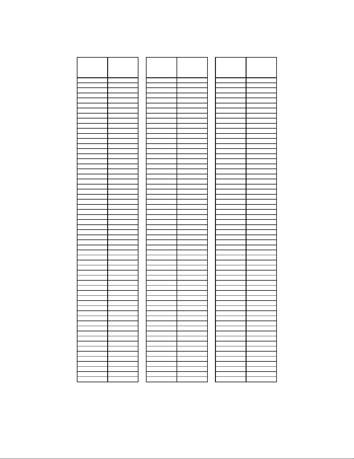
Maintaining proper sensor temperature will prevent the premature failure of the sensor. The
operating temperature of the sensor should remain below 130° F (54°C) at all times. To
determine the sensor temperature, measure the voltage between pins 5(+) and 9(-) on the
microprocessor board. The voltage will be between 0 and 1VDC. Use the chart in Appendix A to
determine the temperature in °F, or use Appendix B to determine the temperature in °C. If this
temperature shows in excess of 130°F (54°C), the length of sample tubing should be increased
to allow for adequate cooling of the sample before it passes the sensor tip.
Calibration of the sensor is recommended annually. SSi’s initial calibration is performed in our
ISO/IEC 17025 certified laboratory, and includes an NIST traceable “Certificate of Calibration”.
Any calibration performed at SSi will be NIST traceable and will have documentation of ISO/IEC
17025 certification. The certificate also indicates the accuracy of the analyzer before and after
calibration. Please contact Super Systems, Inc. at (513) 772-0060 for more information
regarding this service.
It is also possible to calibrate the Simple Dew in the field, which will require one of two optional
calibration kits. One calibration kit is NIST traceable (Part No. 31425); one kit is non-traceable
(Part No. 31030). To perform this calibration, you will need a calibration kit and a voltmeter that
will allow you to measure between 0 and 1 volt DC. Since there is no display on the instrument
itself, the voltages from the sensor circuit board will have to be translated into temperature and
dew point measurements for the purpose of verifying the calibration. The instructions for doing
this are contained in this document along with reference charts to aid in the interpretation of
the voltages.
The calibration kit consists of two bottles of saturated salt solution in which each bottle
generates a precise relative humidity percentage (R.H.%) value. One bottle is 11.3% R.H., and
the other is 75.3% R.H. These two specific calibration points are already pre-programmed into
the microprocessor board.
1.0 Locate the key components within the unit
1.1 The
contains three very small buttons that are used for
calibration. Two are next to one another, and they are marked “75.3%” and “11.3%”,
while the other has no label. The unmarked button is the “Calibrate” button. The
approximate locations of each button are shown on this diagram:
Page 8

Simple Dew Digital Dew Point Analyzer Operations Manual
Super Systems Inc.
Page 8 of 18
sensor-sampling chamber
sensor probe
SPAN
BUTTON
(75.3)
ZERO
BUTTON
(11.3)
CAL
BUTTON
Dew Point Microprocessor Board
1.2 The
is the gray rectangular box with brass barb fittings
on either side with a black plastic gland protruding from the center.
1.3 The
is positioned in the sensor-sampling chamber. It is held in
place by the nut on the black plastic gland.
2.0 Remove the sensor probe from the sensor sampling chamber.
2.1 Loosen the black plastic gland nut and slowly slide the sensor probe out through
the airtight seal. Care must be taken when removing this sensor probe, since the tip
is very delicate and can be easily damaged if it is mishandled. Note that the probe
has white mark at the wire entry point, which must be aligned with corresponding
white mark in plastic gland when it is re-inserted in the sampling chamber.
3.0 Install the sensor probe into the 75.3% salt solution.
3.1 Slip the black sensor gland (supplied in the calibration kit) over the sensor probe
with the sensor tip protruding from the threaded end of the gland and the sensor
wires being flush with the top of the rubber o-ring in the gland. Tighten the gland
around the sensor. This does not need to be done with a wrench or other tools, but it
does need to be tight enough to prevent ambient air from contaminating the humidity
level of the sampling chamber.
3.2 Remove the cap of the 75.3% salt solution and install the sensor gland (with the
sensor) into the salt solution. To increase the life of the calibration salts, an effort
should be made to minimize the amount of time that the salt solution is exposed to
the ambient air.
4.0 Allow the sensor to reach equilibrium with the calibration salt.
Page 9

Simple Dew Digital Dew Point Analyzer Operations Manual
Super Systems Inc.
Page 9 of 18
4.1 Leave the sensor in the calibration salt for a minimum of eighteen (18) hours. It is
acceptable to leave the sensor in the salt solution for a longer period of time, even a
few days, if desired.
5.0 Begin the 75.3% (Span) calibration process.
5.1 After leaving the sensor in the salt for at least eighteen (18) hours, turn the unit
on (if it isn’t on already).
5.2 Simultaneously press the “75.3%” and “Calibration” buttons on the
microprocessor board.
6.0 Verify the 75.3% (Span) calibration.
6.1 Leave the sensor in the 75.3%RH calibration salt.
6.2 Record the temperature and the dew point of the sensor. Since there is no display
on the instrument, you will need to measure the voltage from the microprocessor
board and translate that into the appropriate measurement.
6.2.1 To determine the sensor temperature, measure the voltage between pins
5(+) and 9(-) on the microprocessor board. The voltage will be between 0
and 1VDC. Use the chart in Appendix A to determine the temperature in
°F, or use Appendix B to determine the temperature in °C.
6.2.2 Temporarily record the sensor temperature.
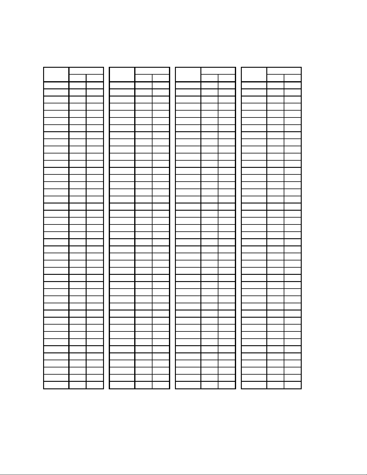
6.3 Look up this temperature in Appendix “C” (Determining the Dew Point in °F) or
Appendix “D” (Determining the Dew Point in °C). Appendix C will show the
temperature values in Fahrenheit, and Appendix D will show the temperature values
in Celsius.
6.4 Next to the appropriate sensor temperature, note the number in the
corresponding column titled “75.3%”. This will match the measured dew point,
which can be verified wherever the dew point is displayed.
7.0 After the 75.3% (Span) calibration has been completed, remove the sensor from the
calibration salt and replace the cap on the salt.
7.1 Leave the sensor probe in the gland and while the unit is still on, allow it to
achieve equilibrium at the ambient atmosphere in the room. This is accomplished by
simply leaving the sensor exposed to ambient air for between two and three minutes.
You will know when this has been accomplished when the numbers on the display
begin to stabilize.
8.0 Install the sensor probe into the 11.3% salt solution.
Page 10

Simple Dew Digital Dew Point Analyzer Operations Manual
Super Systems Inc.
Page 10 of 18
8.1 Remove the cap of the 11.3% salt solution and install the sensor gland (with the
sensor) into the salt solution. To increase the life of the calibration salts, an effort
should be made to minimize the amount of time that the salt solution is exposed to
the ambient air.
9.0 Allow the sensor to reach equilibrium with the calibration salt.
9.1 Leave the sensor in the calibration salt for a minimum of 24 hours. It is acceptable
to leave the sensor in the salt solution for a longer period of time, even a few days, if
desired.
10.0 Begin the 11.3% (Zero) calibration process
10.1 After leaving the sensor in the salt for at least twenty-four (24) hours, turn the
unit on (if it isn’t on already).
10.2 Simultaneously press the “11.3%” and “Calibration” buttons on the
microprocessor board.
11.0 Verify the 11.3% (Zero) calibration
11.1 Leave the sensor in the 11.3%RH calibration salt
11.2 Record the temperature and the dew point of the sensor. Since there is no
display on the instrument, you will need to measure the voltage from the
microprocessor board and translate that into the appropriate measurement.
11.2.1 To determine the sensor temperature, measure the voltage between pins
5(+) and 9(-) on the microprocessor board. The voltage will be between 0
and 1VDC. Use the chart in Appendix A to determine the temperature in
°F, or use Appendix B to determine the temperature in °C.
11.2.2 Temporarily record the sensor temperature.
11.3 Look up this temperature in Appendix “C” (Determining the Dew Point in °F) or
Appendix “D” (Determining the Dew Point in °C). Appendix C will show the
temperature values in Fahrenheit, and Appendix D will show the temperature values
in Celsius.
11.4 Next to the appropriate temperature, note the number in the corresponding
column titled “11.3%”. This will match the measured dew point, which can be
verified wherever the dew point is displayed.
12.0 After the 11.3% (Zero) calibration has been completed, remove the sensor from the
calibration salt and replace the cap on the salt.
Page 11

Simple Dew Digital Dew Point Analyzer Operations Manual
Super Systems Inc.
Page 11 of 18
Replacement Parts
Description
Part Number
Factory Calibration
65010
Calibration Kit (non-traceable)
31030
Calibration Kit (NIST traceable)
31425
Bowl Filter
37048
Bowl Filter Element
31027
Dew Point Sensor
31038
Sensor Sampling Block
20192
Sample Tube
20263
Sample Tube (With High-Temp Filter)
20264
Complete Units
Simple Dew Unit (with Power Supply)
13134
Simple Dew Unit (without Power Supply)
13136
Returning the Unit to SSi
12.1 After the 11.3% (Zero) calibration has been completed, remove the sensor from
the calibration salt and replace the cap.
13.0 Re-assemble the unit
13.1 After the calibration process has been completed, remove the sensor probe from
the gland and return it to the sensor-sampling chamber, taking care to position it
properly. The white mark on the sensor probe should face towards the inlet tubing.
If the white mark is not visible, then it should be placed so the sample flow directly
strikes the face of the mirror on the sensor tip. In other words, the mirror should
face the incoming gas stream.
13.2 Hand-tighten the black sensor gland to prevent air from leaking out of the
sampling chamber.
14.0 Make sure that all caps are replaced on the calibration salts, and return the instrument
to service.
This analyzer contains some components that may require periodic replacement based on the
amount of use that the unit experiences and the methods in which it is used. If service on the
unit is necessary, it should be sent back to Super Systems, Inc. in the original packaging for
repair. If the original packaging is not available, the analyzer should be surrounded by impactabsorbing materials and placed in a box. It is the responsibility of the shipper to ensure that the
Simple Dew arrives at SSi undamaged.
Page 12

Simple Dew Digital Dew Point Analyzer Operations Manual
Super Systems Inc.
Page 12 of 18
Super Systems, Inc.
ATTN: RMA #XXXX
7205 Edington Drive
Cincinnati, OH 45249
Before shipping the analyzer, please call (513) 772-0060 to receive a Return Materials
Authorization (RMA) number. The shipping address that should be used for returns is:
Page 13

Simple Dew Digital Dew Point Analyzer Operations Manual
Super Systems Inc.
Page 13 of 18
Warranty
Limited Warranty for Super Systems Products:
The Limited Warranty applies to new Super Systems Inc. (SSI) products purchased direct from
SSI or from an authorized SSI dealer by the original purchaser for normal use. SSI warrants
that a covered product is free from defects in materials and workmanship, with the exceptions
stated below.
The limited warranty does not cover damage resulting from commercial use, misuse, accident,
modification or alteration to hardware or software, tampering, unsuitable physical or operating
environment beyond product specifications, improper maintenance, or failure caused by a
product for which SSI is not responsible. There is no warranty of uninterrupted or error-free
operation. There is no warranty for loss of data—you must regularly back up the data stored on
your product to a separate storage product. There is no warranty for product with removed or
altered identification labels. SSI DOES NOT PROVIDE ANY OTHER WARRANTIES OF ANY KIND,
INCLUDING, BUT NOT LIMITED TO, THE IMPLIED WARRANTIES OR CONDITIONS OF
MERCHANTABILITY AND FITNESS FOR A PARTICULAR PURPOSE. SOME JURISDICTIONS DO
NOT ALLOW THE LIMITATION OF IMPLIED WARRANTIES, SO THIS LIMITATION MAY NOT APPLY
TO YOU. SSI is not responsible for returning to you product which is not covered by this limited
warranty.
If you are having trouble with a product, before seeking limited warranty service, first follow the
troubleshooting procedures that SSI or your authorized SSI dealer provides.
SSI will replace the PRODUCT with a functionally equivalent replacement product,
transportation prepaid after PRODUCT has been returned to SSI for testing and evaluation. SSI
may replace your product with a product that was previously used, repaired and tested to meet
SSI specifications. You receive title to the replaced product at delivery to carrier at SSI shipping
point. You are responsible for importation of the replaced product, if applicable. SSI will not
return the original product to you; therefore, you are responsible for moving data to another
media before returning to SSI, if applicable. Data Recovery is not covered under this warranty
and is not part of the warranty returns process. SSI warrants that the replaced products are
covered for the remainder of the original product warranty or 90 days, whichever is greater.
Page 14

Simple Dew Digital Dew Point Analyzer Operations Manual
Super Systems Inc.
Page 14 of 18
Revision History
Rev.
Description
Date
MCO#
-
First Release
03-06-2009
N/A
A
Manual updated to current standard format.
units.
04-13-2015
2158
Introduction updated. Specifications updated to
include power requirements specified based on
Simple Dew unit. Calibration instructions updated
to include two calibration kit options.
Replacement parts list updated, including the
addition of two calibration kits and two complete
Page 15
Simple Dew Digital Dew Point Analyzer Operations Manual
Super Systems Inc.
Page 15 of 18
Appendix A: Determining the Sensor Temperature in °F
When the DC
voltage
between 5(+)
and 8(-) is:
Then the
sensor
temperature
(°F) is:
When the DC
voltage
between 5(+)
and 8(-) is:
Then the
sensor
temperature
(°F) is:
When the DC
voltage
between 5(+)
and 8(-) is:
Then the
sensor
temperature
(°F) is:
0.3472 67.0 0.3806 79.0 0.4139 91.0
0.3478 67.2 0.3811 79.2 0.4144 91.2
0.3483 67.4 0.3817 79.4 0.4150 91.4
0.3489
67.6
0.3822
79.6
0.4156
91.6
0.3494 67.8 0.3828 79.8 0.4161 91.8
0.3500 68.0 0.3833 80.0 0.4167 92.0
0.3506
68.2
0.3839
80.2
0.4172
92.2
0.3511
68.4
0.3844
80.4
0.4178
92.4
0.3517
68.6
0.3850
80.6
0.4183
92.6
0.3522 68.8 0.3856 80.8 0.4189 92.8
0.3528 69.0 0.3861 81.0 0.4194 93.0
0.3533 69.2 0.3867 81.2 0.4200 93.2
0.3539 69.4 0.3872 81.4 0.4206 93.4
0.3544 69.6 0.3878 81.6 0.4211 93.6
0.3550 69.8 0.3883 81.8 0.4217 93.8
0.3556
70.0
0.3889
82.0
0.4222
94.0
0.3561 70.2 0.3894 82.2 0.4228 94.2
0.3567 70.4
0.3900
82.4 0.4233 94.4
0.3572 70.6
0.3906
82.6 0.4239 94.6
0.3578 70.8 0.3911 82.8 0.4244 94.8
0.3583 71.0 0.3917 83.0 0.4250 95.0
0.3589 71.2 0.3922 83.2
0.4256 95.2
0.3594 71.4 0.3928 83.4 0.4261 95.4
0.3600 71.6 0.3933 83.6 0.4267 95.6
0.3606 71.8 0.3939
83.8
0.4272 95.8
0.3611 72.0 0.3944 84.0 0.4278 96.0
0.3617
72.2 0.3950 84.2
0.4283
96.2
0.3622
72.4 0.3956 84.4 0.4289 96.4
0.3628 72.6 0.3961
84.6
0.4294 96.6
0.3633 72.8 0.3967 84.8 0.4300 96.8
0.3639 73.0 0.3972 85.0
0.4306 97.0
0.3644 73.2 0.3978 85.2 0.4311 97.2
0.3650
73.4 0.3983 85.4 0.4317 97.4
0.3656 73.6 0.3989 85.6 0.4322 97.6
0.3661 73.8 0.3994
85.8 0.4328 97.8
0.3667 74.0 0.4000 86.0 0.4333 98.0
0.3672 74.2 0.4006 86.2 0.4339 98.2
0.3678 74.4 0.4011 86.4 0.4344 98.4
0.3683 74.6 0.4017 86.6 0.4350 98.6
0.3689 74.8 0.4022 86.8 0.4356 98.8
0.3694 75.0 0.4028 87.0 0.4361 99.0
0.3700 75.2 0.4033 87.2 0.4367 99.2
0.3706 75.4 0.4039 87.4 0.4372 99.4
0.3711 75.6 0.4044 87.6 0.4378 99.6
0.3717 75.8 0.4050 87.8 0.4383 99.8
0.3722 76.0 0.4056 88.0 0.4389 100.0
0.3728
76.2 0.4061 88.2 0.4394 100.2
0.3733 76.4 0.4067 88.4 0.4400 100.4
0.3739 76.6 0.4072 88.6 0.4406
100.6
0.3744 76.8 0.4078 88.8 0.4411 100.8
0.3750 77.0 0.4083 89.0 0.4417 101.0
0.3756 77.2 0.4089 89.2 0.4422 101.2
0.3761
77.4
0.4094
89.4
0.4428
101.4
0.3767 77.6 0.4100 89.6 0.4433 101.6
0.3772 77.8 0.4106 89.8 0.4439 101.8
0.3778 78.0 0.4111 90.0 0.4444 102.0
0.3783 78.2 0.4117 90.2 0.4450 102.2
0.3789 78.4 0.4122 90.4 0.4456 102.4
0.3794
78.6
0.4128
90.6
0.4461
102.6
0.3800 78.8 0.4133 90.8 0.4467 102.8
Page 16

Simple Dew Digital Dew Point Analyzer Operations Manual
Super Systems Inc.
Page 16 of 18
Appendix B: Determining the Sensor Temperature in °C
When the DC
voltage
between 5(+)
and 8(-) is:
Then the
sensor
temperature
(°C) is:
When the DC
voltage
between 5(+)
and 8(-) is:
Then the
sensor
temperature
(°C) is:
When the DC
voltage
between 5(+)
and 8(-) is:
Then the
sensor
temperature
(°C) is:
0.3472 19.4
0.3806 26.1
0.4139 32.8
0.3478 19.6 0.3811
26.2 0.4144
32.9
0.3483
19.7 0.3817
26.3 0.4150
33.0
0.3489 19.8 0.3822
26.4
0.4156 33.1
0.3494
19.9 0.3828
26.6 0.4161
33.2
0.3500
20.0 0.3833 26.7 0.4167
33.3
0.3506 20.1
0.3839 26.8
0.4172 33.4
0.3511 20.2 0.3844
26.9 0.4178
33.6
0.3517
20.3 0.3850
27.0 0.4183
33.7
0.3522 20.4 0.3856
27.1 0.4189 33.8
0.3528
20.6 0.3861
27.2 0.4194
33.9
0.3533
20.7 0.3867 27.3 0.4200
34.0
0.3539 20.8
0.3872 27.4
0.4206 34.1
0.3544 20.9
0.3878 27.6 0.4211
34.2
0.3550
21.0 0.3883 27.7 0.4217
34.3
0.3556
21.1 0.3889 27.8
0.4222 34.4
0.3561 21.2
0.3894 27.9 0.4228
34.6
0.3567
21.3 0.3900
28.0 0.4233
34.7
0.3572
21.4 0.3906 28.1
0.4239 34.8
0.3578 21.6 0.3911 28.2 0.4244 34.9
0.3583 21.7 0.3917 28.3
0.4250 35.0
0.3589
21.8
0.3922 28.4 0.4256 35.1
0.3594
21.9 0.3928 28.6 0.4261 35.2
0.3600 22.0 0.3933 28.7
0.4267 35.3
0.3606 22.1 0.3939 28.8 0.4272 35.4
0.3611 22.2 0.3944 28.9 0.4278
35.6
0.3617 22.3
0.3950 29.0 0.4283 35.7
0.3622 22.4 0.3956 29.1
0.4289
35.8
0.3628 22.6 0.3961
29.2 0.4294 35.9
0.3633 22.7 0.3967 29.3 0.4300 36.0
0.3639 22.8
0.3972 29.4 0.4306 36.1
0.3644
22.9 0.3978 29.6 0.4311 36.2
0.3650 23.0 0.3983 29.7 0.4317 36.3
0.3656 23.1 0.3989 29.8 0.4322 36.4
0.3661 23.2 0.3994
29.9 0.4328 36.6
0.3667
23.3 0.4000 30.0
0.4333 36.7
0.3672
23.4 0.4006 30.1 0.4339
36.8
0.3678
23.6 0.4011 30.2
0.4344 36.9
0.3683 23.7 0.4017 30.3
0.4350 37.0
0.3689
23.8 0.4022 30.4
0.4356 37.1
0.3694
23.9 0.4028 30.6
0.4361 37.2
0.3700 24.0 0.4033 30.7
0.4367 37.3
0.3706
24.1 0.4039 30.8
0.4372 37.4
0.3711
24.2 0.4044 30.9
0.4378 37.6
0.3717 24.3 0.4050 31.0
0.4383 37.7
0.3722
24.4 0.4056 31.1 0.4389 37.8
0.3728 24.6 0.4061 31.2 0.4394 37.9
0.3733 24.7 0.4067 31.3 0.4400
38.0
0.3739 24.8 0.4072 31.4 0.4406 38.1
0.3744 24.9 0.4078 31.6 0.4411 38.2
0.3750 25.0 0.4083 31.7
0.4417 38.3
0.3756 25.1
0.4089
31.8
0.4422 38.4
0.3761 25.2 0.4094 31.9 0.4428 38.6
0.3767 25.3 0.4100 32.0 0.4433 38.7
0.3772 25.4 0.4106 32.1
0.4439
38.8
0.3778 25.6 0.4111 32.2
0.4444 38.9
0.3783 25.7 0.4117 32.3
0.4450 39.0
0.3789 25.8 0.4122 32.4
0.4456 39.1
0.3794 25.9
0.4128 32.6 0.4461 39.2
0.3800 26.0 0.4133 32.7 0.4467 39.3
Page 17

Simple Dew Digital Dew Point Analyzer Operations Manual
Super Systems Inc.
Page 17 of 18
Appendix C: Determining the Dew Point in °F
Sensor Sensor
Sensor Sensor
Temp (°F) 11.3% 75.3%
Temp (°F) 11.3% 75.3% Temp (°F) 11.3% 75.3% Temp (°F) 11.3% 75.3%
67.0
11.38 58.94
75.6
18.06
67.24
84.1 24.70 75.53 92.8 31.31 83.82
67.2
11.54 59.13
75.8
18.21
67.43
84.2 24.85 75.73 93.0 31.46 84.01
67.4
11.69 59.32
76.0
18.37 67.62
84.3
25.01 75.92
93.2
31.61 84.21
67.6 11.85 59.52 76.2 18.52 67.82 84.4 25.16 76.11 93.4 31.77 84.40
67.8
12.00 59.71
76.4
18.68 68.01
84.5 25.32 76.30
93.6
31.92 84.59
68.0 12.16 59.90 76.6 18.83 68.20 85.2 25.47
76.50
93.8
32.07 84.78
68.2
12.31 60.09
76.8
18.99 68.40
85.4 25.63
76.69 94.0 32.23 84.98
68.4
12.47 60.29
77.0
19.14 68.59
85.6
25.78
76.88
94.2 32.38 85.17
68.6
12.63 60.48
77.2
19.30 68.78
85.8
25.94 77.07
94.4
32.53 85.36
68.8 12.78 60.67 77.4 19.45 68.97 86.0 26.09 77.27
94.6
32.69 85.55
69.0
12.94 60.86 77.6 19.61 69.17 86.2 26.24 77.46 94.8 32.84 85.75
69.2
13.09 61.06 77.8 19.76 69.36 86.4 26.40 77.65 95.0 32.99 85.94
69.4
13.25
61.25 78.0
19.91 69.55 86.6 26.55 77.85 95.2 33.14 86.13
69.6
13.40 61.45 78.2 20.07 69.75 86.8 26.70
78.04
95.4
33.30 86.32
69.8 13.56
61.64 78.4 20.22 69.94 87.0
26.86 78.23 95.6
33.45 86.52
70.0 13.71 61.83 78.6 20.38
70.13
87.2
27.01 78.42 95.8 33.60 86.71
70.2
13.87 62.03 78.8 20.53 70.33 87.4 27.17 78.62 96.0
33.76 86.90
70.4
14.02 62.22 79.0 20.69 70.52 87.6 27.32 78.81 96.2
33.91 87.09
70.6 14.18
62.41
79.2
20.84 70.71 87.8 27.47 79.00 96.4 34.06 87.29
70.8 14.33 62.60 79.4 21.00 70.90 88.0 27.63 79.19 96.6 34.21
87.48
71.0 14.49 62.80 79.6 21.15 71.10 88.2
27.78 79.39 96.8 34.37 87.67
71.2 14.65 62.99 79.8 21.31 71.29 88.4 27.93 79.58 97.0 34.52 87.87
71.4 14.80 63.18 80.0 21.46 71.48 88.6 28.09
79.77 97.2 34.67 88.06
71.6 14.96 63.38 80.2 21.61 71.68 88.8 28.24 79.97 97.4 34.82 88.25
71.8 15.11 63.57 80.4 21.77 71.87 89.0 28.39 80.16 97.6 34.98 88.44
72.0 15.27 63.76 80.6 21.92 72.06 89.2 28.55 80.35 97.8 35.13 88.64
72.2 15.42 63.96 80.8 22.08 72.25 89.4 28.70 80.54 98.0
35.28 88.83
72.4
15.58 64.15
81.0
22.23 72.44
89.6
28.85 80.74 98.2 35.44 89.02
72.6 15.73 64.34 81.2 22.39 72.64 89.8 29.01 80.93 98.4 35.59 89.21
72.8 15.89
64.54 81.4 22.54 72.83 90.0 29.16 81.12 98.6 35.74 89.41
73.0 16.04 64.73 81.6 22.70 73.03
90.2 29.32 81.31 98.8 35.89 89.60
73.2 16.20 64.92 81.8 22.85 73.22 90.4 29.47 81.51 99.0 36.05 89.79
73.4 16.35 65.11 82.0 23.00 73.41 90.6 29.62 81.70 99.2 36.20 89.98
73.6 16.51 65.31 82.2 23.16 73.60 90.8 29.78
81.89 99.4 36.35 90.18
73.8 16.66 65.50 82.4 23.31 73.80 91.0 29.93
82.09 99.6 36.50 90.37
74.0 16.82 65.69 82.6 23.47 73.99
91.2 30.08 82.28 99.8 36.66 90.56
74.2 16.97 65.89
82.8 23.62 74.18 91.4 30.24 82.47 100.0 36.81 90.75
74.4 17.13 66.08 83.0 23.77 74.38 91.6 30.39 82.66 100.2 36.96 90.95
74.6 17.28
66.27 83.2 23.93 74.57 91.8 30.54 82.86 100.4 37.11 91.14
74.8 17.44 66.47 83.4 24.08 74.76 92.0 30.69 83.05 100.6 37.27 91.33
75.0 17.59 66.66 83.6 24.24 74.95 92.2 30.85 83.24 100.8 37.42 91.52
75.2 17.75 66.85 83.8 24.39 75.15 92.4 31.00 83.43 101.0 37.57 91.72
75.4 17.90 67.04 84.0
24.55 75.34 92.6 31.15 83.63 101.2 37.72 91.91
Percent RH
Percent RH
Percent RH
Percent RH
Page 18
Simple Dew Digital Dew Point Analyzer Operations Manual
Super Systems Inc.
Page 18 of 18
Appendix D: Determining the Dew Point in °C
Sensor Sensor
Sensor Sensor
Temp (°F) 11.3% 75.3%
Temp (°F) 11.3% 75.3% Temp (°F) 11.3% 75.3% Temp (°F) 11.3% 75.3%
19.4
-11.46 14.97
24.2
-7.74
19.58
28.9 -4.06 24.18 33.8 -0.38 28.79
19.6
-11.37 15.07
24.3
-7.66
19.68
29.0 -3.97 24.29 33.9 -0.30 28.89
19.7
-11.28 15.18
24.4
-7.57 19.79
29.1
-3.88 24.40
34.0
-0.22 29.01
19.8 -11.19 15.29 24.6 -7.49 19.90 29.1 -3.80 24.51 34.1 -0.13 29.11
19.9
-11.11 15.39
24.7
-7.40 20.01
29.2 -3.71 24.61
34.2
-0.04 29.22
20.0 -11.02 15.50 24.8 -7.32 20.11 29.6 -3.63
24.72
34.3
0.04 29.32
20.1
-10.94 15.61
24.9
-7.23 20.22
29.7 -3.54
24.83 34.4 0.13 29.43
20.2
-10.85 15.72
25.0
-7.14 20.33
29.8
-3.46
24.93
34.6 0.21 29.54
20.3
-10.76 15.82
25.1
-7.06 20.43
29.9
-3.37 25.04
34.7
0.29 29.64
20.4 -10.68 15.93 25.2 -6.97 20.54 30.0 -3.28 25.15
34.8
0.38 29.75
20.6
-10.59 16.03 25.3 -6.88 20.65 30.1 -3.20 25.26 34.9 0.47 29.86
20.7
-10.51 16.14 25.4 -6.80 20.76 30.2 -3.11 25.36 35.0 0.55 29.97
20.8
-10.42
16.25 25.6
-6.72 20.86 30.3 -3.03 25.47 35.1 0.63 30.07
20.9
-10.33 16.36 25.7 -6.63 20.97 30.4 -2.94
25.58
35.2
0.72 30.18
21.0 -10.24
16.47 25.8 -6.54 21.08 30.6
-2.86 25.68 35.3
0.81 30.29
21.1
-10.16 16.57 25.9 -6.46 21.18 30.7 -2.77 25.79 35.4
0.89 30.39
21.2
-10.07 16.68
26.0
-6.37 21.29 30.8 -2.68 25.90 35.6
0.98 30.50
21.3
-9.99 16.79 26.1 -6.28 21.40 30.9 -2.60 26.01 35.7 1.06 30.61
21.4 -9.90 16.89 26.2 -6.20 21.51 31.0
-2.52 26.11
35.8
1.14 30.72
21.6 -9.82
17.00 26.3 -6.11 21.61 31.1 -2.43 26.22 35.9 1.23 30.82
21.7 -9.73 17.11 26.4 -6.03 21.72 31.2 -2.34 26.33 36.0 1.32
30.93
21.8 -9.64 17.22
26.6 -5.94 21.83 31.3 -2.26 26.43 36.1 1.40 31.04
21.9 -9.56 17.32 26.7 -5.86 21.93 31.4 -2.17 26.54 36.2 1.48 31.14
22.0 -9.47 17.43 26.8
-5.77 22.04 31.6 -2.09 26.65 36.3 1.57 31.25
22.1
-9.38 17.54
26.9
-5.68 22.15 31.7 -2.01 26.76 36.4 1.66 31.36
22.2
-9.29 17.64
27.0
-5.60 22.26 31.8 -1.92 26.86 36.6 1.74 31.47
22.3
-9.21 17.76
27.1
-5.51 22.36 31.9 -1.83 26.97 36.7 1.82 31.57
22.4 -9.12 17.86 27.2 -5.43 22.47 32.0 -1.75 27.08 36.8
1.91 31.68
22.6 -9.04 17.97 27.3 -5.34 22.58 32.1 -1.66 27.18 36.9 1.99 31.78
22.7 -8.95 18.08 27.4 -5.26 22.68
32.2 -1.58 27.29 37.0 2.08 31.89
22.8 -8.87 18.18 27.6 -5.17 22.79 32.3 -1.49 27.39 37.1 2.16
32.00
22.9 -8.78 18.29 27.7 -5.08 22.90 32.4
-1.41 27.51 37.2 2.25 32.11
23.0 -8.69 18.39
27.8 -5.00 23.01 32.6 -1.32 27.61 37.3 2.33 32.21
23.1 -8.61 18.51 27.9 -4.91 23.11 32.7 -1.23 27.72 37.4 2.42 32.32
23.2 -8.52 18.61 28.0 -4.83 23.22 32.8 -1.15 27.83 37.6 2.50 32.43
23.3 -8.43 18.72 28.1 -4.74 23.33 32.9 -1.07 27.93 37.7 2.59 32.53
23.4 -8.35 18.83 28.2 -4.66 23.43 33.0 -0.98 28.04 37.8
2.67 32.64
23.6 -8.26 18.93 28.3 -4.57 23.54
33.1 -0.89 28.14 37.9 2.76 32.75
23.7 -8.18 19.04 28.4
-4.48 23.65 33.2 -0.81 28.26 38.0 2.84 32.86
23.8 -8.09 19.15 28.6 -4.40 23.76 33.3 -0.73 28.36 38.1 2.93 32.96
23.9 -8.01 19.26 28.7 -4.31
23.86 33.4 -0.64 28.47 38.2 3.01 33.07
24.0 -7.92 19.36 28.8 -4.23 23.97 33.6 -0.56 28.57 38.3 3.09 33.18
24.1 -7.83 19.47 28.9
-4.14 24.08 33.7 -0.47 28.68 38.4 3.18 33.28
Percent RH
Percent RH
Percent RH
Percent RH
 Loading...