

Page 1

SD Recorder II
Operations Manual
COPYRIGHT
No part of this publication may be reproduced, transmitted, transcribed, stored in a retrieval system, or translated into any
language or computer language, in any form or by any means, elect ronic, mechanical, magnetic, optical, chemical, manual, or
otherwise, without prior written permis sion of Super Systems Inc., 7205 Edington Dr., Cincinnati, OH 45249 USA.
SuperDATA is a suite of software programs to be used by the Heat Treater. Super Systems Inc . is not responsible or liable for any
product, process, or damage or injury incurred as a result of using SuperDATA. Super Systems Inc. makes no representations or
warranties with respect to the contents hereof and s pecifically disclaim any implied warranties or merchantability or fitness for any
particular purpose.
DISCLAIMER
Super Systems Inc.
7205 Edington Drive
Cincinnati, OH 45249
513-772-0060 / 800-666-4330
Fax: 513-772-9466
www.supersystems.com
Super Systems Inc. Page 1 of 50 SD Recorder II Operations Manual
Page 2

Table of Contents
Overview ................................................................................................................................................... 5
Menu and Toolbar..................................................................................................................................... 6
File Menu .............................................................................................................................................. 6
View Menu ............................................................................................................................................ 8
Chart Menu ........................................................................................................................................... 9
Tools Menu ......................................................................................................................................... 10
Options Menu ..................................................................................................................................... 10
Toolbar ................................................................................................................................................ 10
Left Pane Area ......................................................................................................................................... 11
Chart and Pen Settings ........................................................................................................................ 11
General Chart Settings ........................................................................................................................ 12
Chart Pens ............................................................................................................................................... 13
Normal Pens ........................................................................................................................................ 13
Pen Backups ........................................................................................................................................ 15
Pen Backup Settings ............................................................................................................................ 15
Special Pens and the SD Expression Editor ......................................................................................... 17
Expression Editor for Tag Pen ............................................................................................................. 17
Expression Editor for Special Pen........................................................................................................ 18
The Chart Area ........................................................................................................................................ 19
The Cursor and Legend ....................................................................................................................... 20
Plot Area Menu ................................................................................................................................... 22
Chart Control Area .................................................................................................................................. 22
Window Width .................................................................................................................................... 22
Time Span Editor ................................................................................................................................. 23
Start and End DateTime values ........................................................................................................... 23
Window Width Mode.......................................................................................................................... 23
Time slider ........................................................................................................................................... 24
Scroll Data buttons .............................................................................................................................. 24
RealTime button.................................................................................................................................. 24
Chart Scale Selection- ......................................................................................................................... 24
Super Systems Inc. Page 2 of 50 SD Recorder II Operations Manual
Page 3

Left Pane List Views ................................................................................................................................ 25
Data Tab .............................................................................................................................................. 25
Notes Tab ............................................................................................................................................ 25
Alarm Tab - .......................................................................................................................................... 26
Recipe Tab ........................................................................................................................................... 26
Run Mode ........................................................................................................................................ 27
Preview Mode ................................................................................................................................. 27
Edit Mode ........................................................................................................................................ 28
The Search Tool ................................................................................................................................... 29
Printing a Chart Report ........................................................................................................................... 30
Exporting Data ........................................................................................................................................ 31
Exporting to a CSV/TSV file ................................................................................................................. 31
Users ....................................................................................................................................................... 32
Starting SDRecorderII with Command Line Arguments .......................................................................... 33
SDRecorderII Operating Modes .............................................................................................................. 34
Operating Mode Details .......................................................................................................................... 35
Mode: SDIO – Online ........................................................................................................................... 35
Mode: SDIO – Alternate ...................................................................................................................... 35
Mode: Data Center – Online .............................................................................................................. 36
Mode: Data Center – Alternate .......................................................................................................... 36
Restricted Operating Modes ............................................................................................................... 37
Limiting Operating Modes - Examples ................................................................................................ 37
Using Automatic Update Feature ........................................................................................................... 38
Appendix ................................................................................................................................................. 39
Batch System Option ........................................................................................................................... 39
Installation of the Option ................................................................................................................ 39
Activation of the Batch Option ....................................................................................................... 39
Configuration of the Database ........................................................................................................ 40
Adding System Data ........................................................................................................................ 41
Furnace Data ............................................................................................................................... 41
Part Data ..................................................................................................................................... 41
Customer Data ............................................................................................................................ 42
Super Systems Inc. Page 3 of 50 SD Recorder II Operations Manual
Page 4

Using the Load Tracking System ..................................................................................................... 43
New Batch Loads ......................................................................................................................... 43
Current Batch Loads .................................................................................................................... 46
Batch Load History ...................................................................................................................... 47
Searching Loads .......................................................................................................................... 49
Revision History ...................................................................................................................................... 50
Super Systems Inc. Page 4 of 50 SD Recorder II Operations Manual
Page 5
Overview
1
2
3
4
5
Purpose: The SuperDATA Recorder II Program is a video chart recorder that is capa ble
of displaying historical and r eal time process data, notes and alarms. The Recorder is
multi mode capable and can connect to both Data Center (SDC Mode) and SDIO log
data (SDIO Mode), and also to offline archived data.
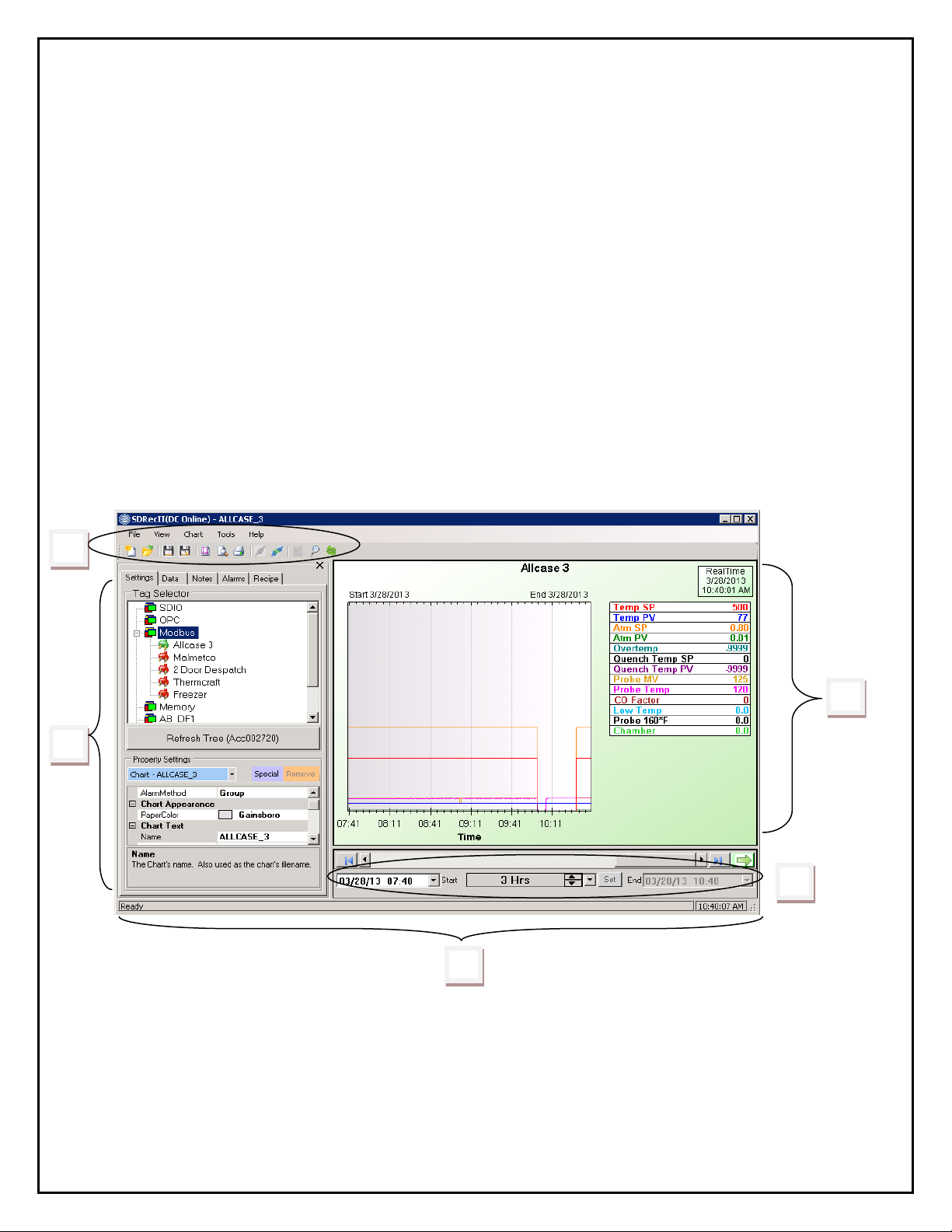
Recorder Screen Layout
The Recorder screen consists of five areas:
1. Menu and Toolbar
2. Left Pane Area
3. Chart Area
4. Chart Control Area
5. Status bar
Super Systems Inc. Page 5 of 50 SD Recorder II Operations Manual
Page 6
Menu and Toolbar
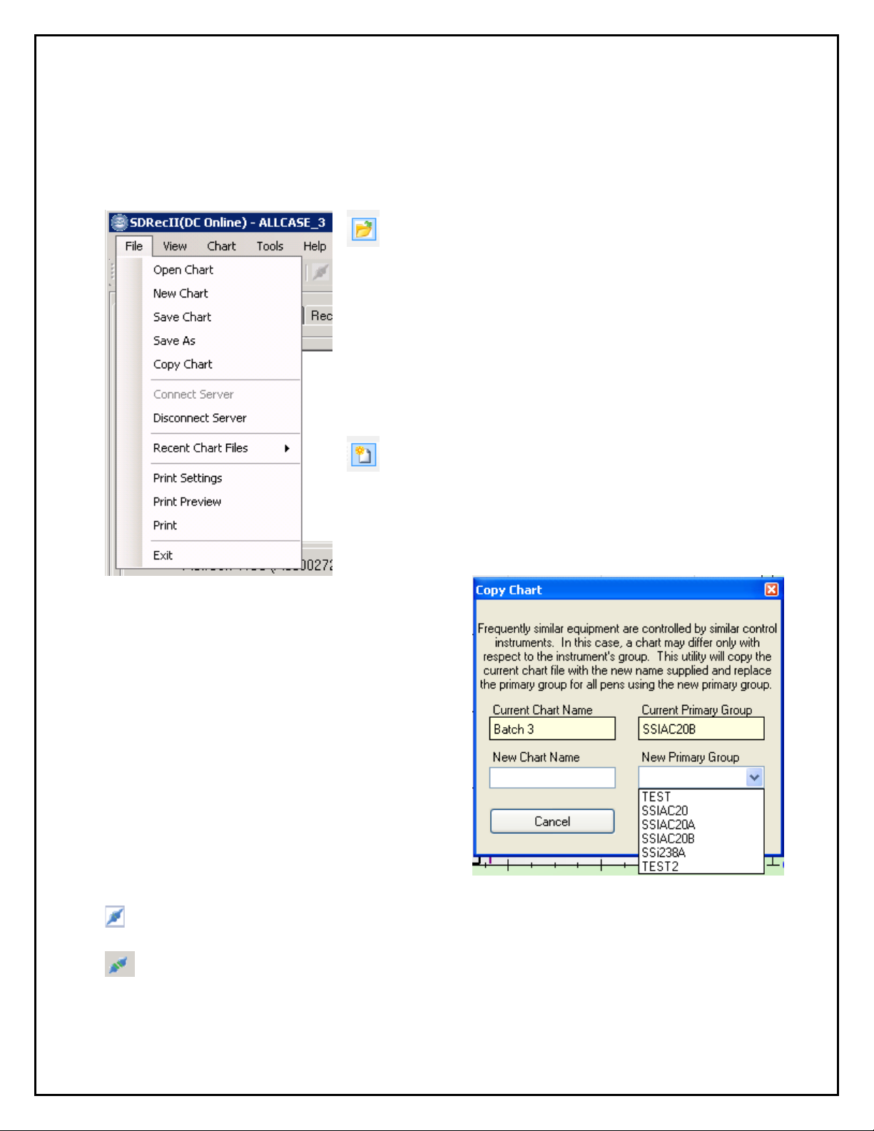
File Menu
Open Chart – Opens a dialog to select an existing
chart definition file from the default trend chart
directory. This menu item is the same as clicking on the
“Open File” icon on the toolbar.
If SDRecorder is operating in SDIO mode opening a
legacy trend chart file (*.ctm) will automatically convert
the file to a chart definition file (*.sd x) . The original
.ctm file will be retained.
If SDRecorder is operating in Data Center mode all the
charts will have a *.sdc extension.
New Chart – Opens a new chart definition file.
This menu item is the same as clicking on the “New
Chart” icon on the toolbar.
Copy Chart – Opens a Copy Chart dialog box
that allows you to “Clone” the chart and pen
settings to an identical furnace with a different
name and Primary Group, (Channel), number.
Connect Server- Establishes a connection to the server computer data source,
either SDIO or Data Center.
Disconnect Server- Breaks the connection to the server c omputer data sourc e.
Super Systems Inc. Page 6 of 50 SD Recorder II Operations Manual
Page 7
Save Chart – Saves the chart definitio n fil e. On the toolbar, there are “Save”
and “Save As” icons. Using the Save menu or the Save icon will save the chart with the
“Name” supplied in the Chart Settings. Using the “Save As” icon will give you a chance
to change the name. Changing the name will also change the chart's “Name” in the
Chart Settings.
Recent Chart Files - Allows you to open a chart from a list of the “most recently
used” chart files.
Print Settings – Opens the “SDRecorderII Print Settings” d ialog. Allows you to
select what will be printed wit h the chart as well as common printer settings. This menu
item provides the same functionality as clicking on the “Print Setup” icon on the toolbar.
Print Preview – Opens a preview window for the report. This menu item is the
same as clicking on the “Print Preview” icon on the toolbar.
Print – Prints the report. This menu item provides the same functionality as clicking
on the “Print” icon on the toolbar. Note: Printing can be done from the Print Preview
dialog and the Print Preview dialog can be opened from the Print Settings dialog.
Super Systems Inc. Page 7 of 50 SD Recorder II Operations Manual
Page 8
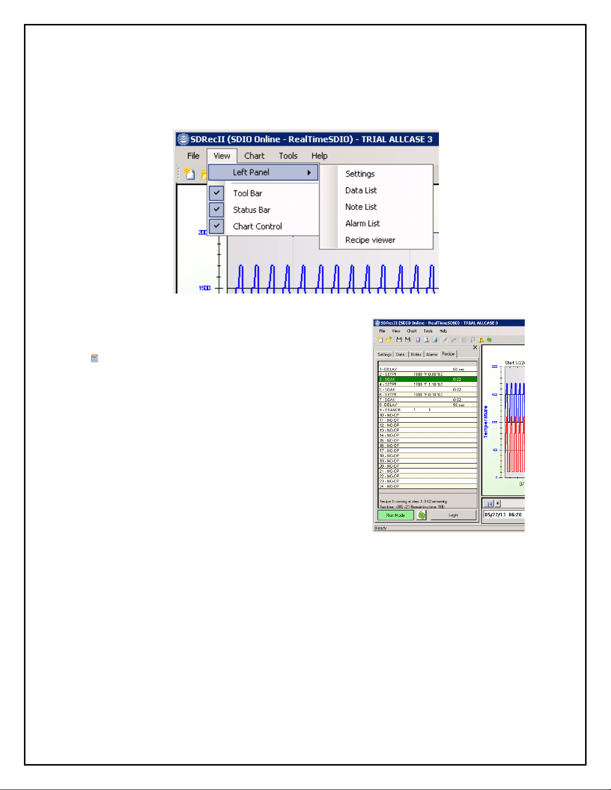
View Menu
The View Menu controls what areas of the screen are displayed.
Left Panel – The left panel is a multipurpose
tabbed panel that may be used to display the
Chart Settings, Data List, Note List, Alarm List,
or Recipe. The left panel may be closed by
clicking the X in the upper right corner of the
panel. The left panel may also be opened by
using the “Left Panel” icon on the toolbar.
Tool Bar – Displays (checked) or hides the toolbar area.
Status Bar – Displays (checked) or hides the status bar area.
Chart Control – displays (checked) or hides the Chart Control area.
Super Systems Inc. Page 8 of 50 SD Recorder II Operations Manual
Page 9
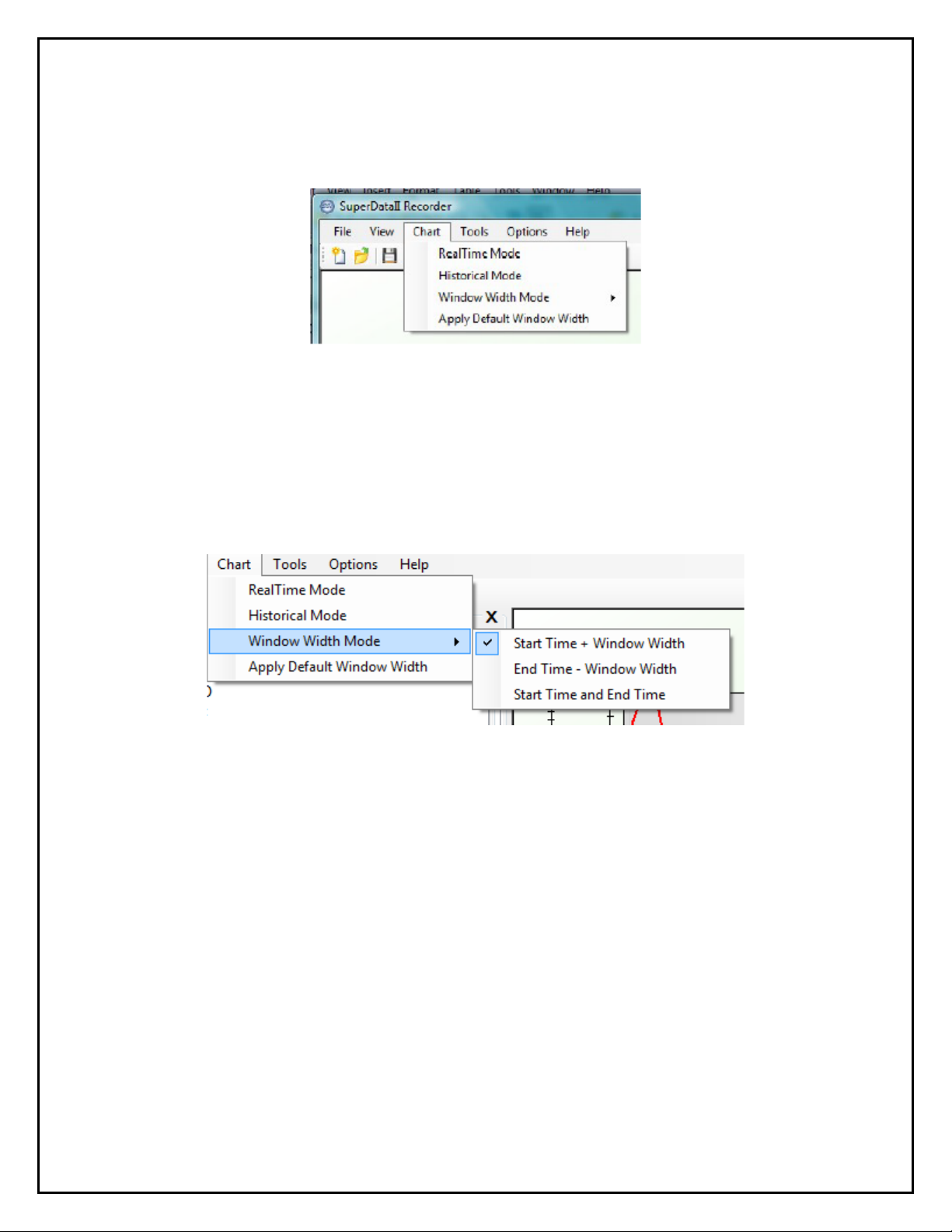
Chart Menu
The Chart Menu is used to control the operating modes of the trend chart.
RealTime Mode – Sets the RealTime mode – the chart updates in one
minute intervals. The chart area ba c kground color will be light green.
Historical Mode – Sets the chart in Historical mode. The chart area
background color will be light blue.
Window Width Mode – There are 3 methods to speci f y the window
width. The specified method will c ontrol which inputs are active in the
Chart Control area.
Start Time + Window Width – Start and Window Width inputs
are active, End is not active. This is the default mode.
End Time + Window Width – End and Window Width are active,
Start is not active.
Start Time and End Time – Start and End are active, Window
Width is not active. This is the mode m ost commonly used for
“Load Reports” where the Load-In and Load-Out times are known.
Apply Default Window Width – this applies the default Window Width
from the Chart Settings.
Super Systems Inc. Page 9 of 50 SD Recorder II Operations Manual
Page 10
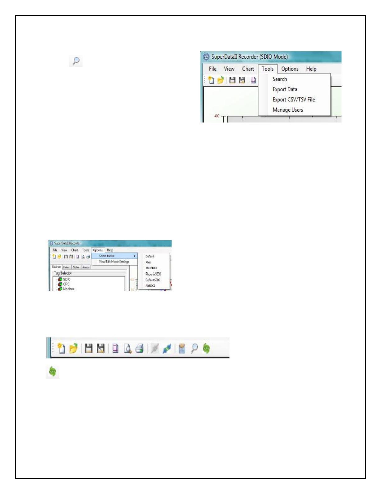
Tools Menu
Search – Opens the Search
Dialog for Searching Notes for
specified text. The Search icon on the
toolbar also opens the search dialog.
(discussed in the Search Tool topic,
Page 29).
Export Data – Opens the Export Data Dialo g for exporting the Data Center's
data to an archive that can be used to view charts offline.
Export CSV/TSV file – Opens a dialog to export current chart data to a CSV or
TSV file for use in a spreadsheet or other application.
Manage Users – Opens the Manage Users dialog. (Discussed in the Users topic,
Page 32).
Options Menu
The options menu allows you to select or edit program modes for SDRecorderII.
Select Mode – Allows you to select from a list
of existing named operating modes.
View/Edit Mode Settings – Allows you to
view, create or edit named mode settings. See
Page 34 for details.
Toolbar
Most of the toolbar icons have been discussed above. One has not: the Refresh icon.
• The Refresh icon refreshes the chart d i sp l ay.
Super Systems Inc. Page 10 of 50 SD Recorder II Operations Manual
Page 11
Left Pane Area
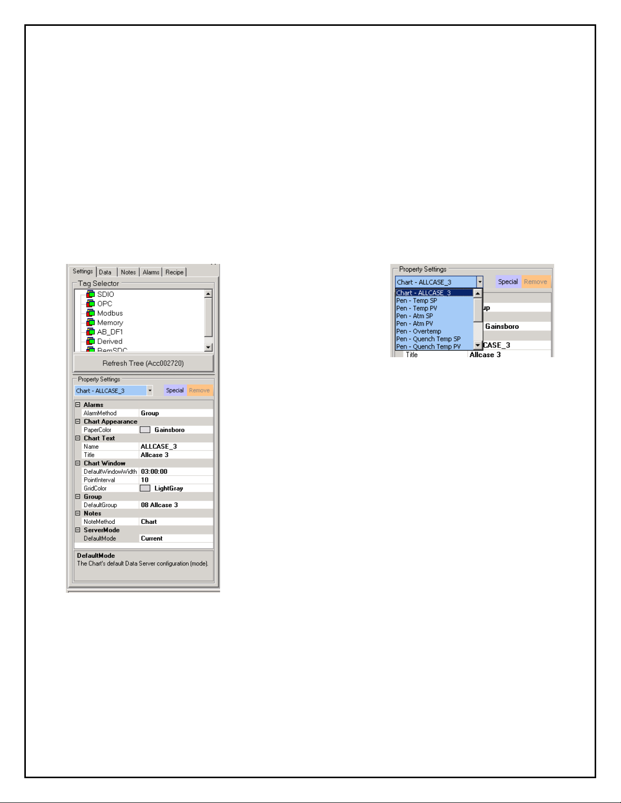
Chart and Pen Settings
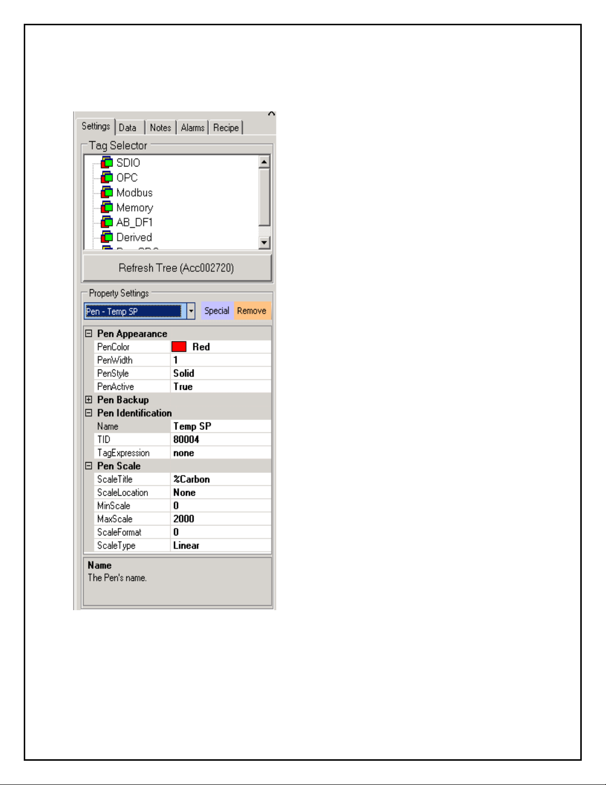
Chart settings define a “Chart”. The Settings tab in the left pane contains a “Tag
Selector” Tree. The Tag Selector will be bordered in red when the ser v er is not
connected. Belo w the Tree is a “Refresh Tree ” button that can be used to get a fresh
copy of the tree.
Below the Tag Selector is a “Property Settings” window. The “Property Settings”
window is used to view and edit the g en eral chart settings and the chart's pen settings.
At the top of the Property Setting box are 3 controls:
Settings Selector –
Provides a dropdown list of
chart items. The first item
is always the chart's
general settings. Foll owing
items are Pens contained in the cha r t.
Special button – used to add pens that are “derived”
from one or more tags.
Remove button – button used to r emove the selected
pen.
Super Systems Inc. Page 11 of 50 SD Recorder II Operations Manual
Page 12
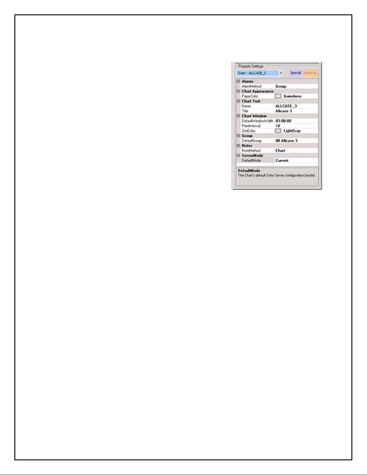
General Chart Settings
Alarm Method – Selects what alarms should be
displayed on the chart. Settings are:
All – Displays all alarms.
Group – Displays alarms only for the chart's
Default Group.
None – No alarms are displayed.
Paper Color – Sets the color of the chart paper.
Name – Sets the name of this chart. This name is also
used as the filename with an extension of . sd x (SDIO
Mode) or .sdc, (SDC Mode).
Title – Sets the title text that appears at the top of the
chart.
Default Window Width – Sets the default window.
Expressed as a “timesp an” variable d.hh:mm:ss where d is days, hh is hours, mm is
minutes and ss is seconds. This value can range from 5 minutes to 10 days. (NOTE:
Days and hours are separated by a decimal point, whereas the other values are
separated by colons.)
Grid Color – Sets the color of the grid lines in the plot area.
Default Group – This is the group used for the Alarm, Note Group modes and Recipe
Viewer tab. When the first Pen is added, the Default Group is set to that Pen's par ent
group; the group may be changed if desired.
Note Method – This setting selects what notes should be displayed on the chart.
The Settings are:
All – displays all notes.
Chart – displays all notes associated with this chart .
Group – displays all notes associated with this chart ' s Default Group.
None – no notes are displayed.
Super Systems Inc. Page 12 of 50 SD Recorder II Operations Manual
Page 13

Chart Pens
Pens plot the tr en d lines on the chart. There are 2 types of pens:
Normal Pens
Normal Pens are pens that plot a tags value (for example, Temperature, Temperature
Setpoint, etc.). Normal pens are added to a chart using the “Tag Selector” tree. Right
clicking a tag in the tree will display a menu with “Add Pen”, the Tag's ID (TID), and a
snapshot of the tag's current value. Clicking “Add Pen” will add the pen to the chart and
set the propert ies window below for the new pen.
Special Pens
Special Pens are pens that are derived from more tha n one tag value (for example,
Average Temperature). Special Pens are added to a chart using t he “ Special” button.
This button opens the “SD Expression Editor” described on Page 17.
Pen Settings
• Pen Color – Color of the pen on the cha r t.
• Pen Width – Width of the pen line on the chart.
• Pen Active – True or False – when false, the pen and the pen's sca les will not
be displayed on the chart, legend, lists or printed reports.
• Pen Backup – These settings di scussed below.
• Name – Name displayed for this pen in the Chart Legend.
• TID – The TagID for a Normal pen. For a Special pen, thi s w i ll be an index
based on the number of Special Pens in the chart.
• TagExpression – Expression used to define a function of the Tag or for
“Special” pens a function of more t han one Tag.
• Scale Title – Title to print with scale – leave blank for no tit le (thi s w i ll save
space).
• Scale Location - Ther e are 3 options:
1. None – scale not displayed
2. Left – displayed on the left
3. Right – displayed on the right
• Min Scale – Minimum Scale value for this pen.
• Max Scale – Maximum Scale value for this pen.
• Min Scale – Minimum Scale value for this pen.
• Scale Format – format string for this scale – also used to format the pen values
displayed in the Chart Legend.
• Scale Type – Normally Linear. Exponent and Log are also a vailable for exponent
or log data.
Super Systems Inc. Page 13 of 50 SD Recorder II Operations Manual
Page 14
Pen Settings
Pen Color – Color of the pen on the char t.
Pen Width – Width of the pen line on the
chart.
Pen Active – True or False – when false, the
pen and the pen's scales will not be disp layed
on the chart, legend, lists or printed reports.
Pen Backup – These settings discussed
below.
Name – Name displayed for this pen in the
Chart Legend.
TID – The TagID for a Normal pen (with SDIO,
the TagID is (channel * 10000 + slot) . Fo r a
Special pen, this will be an index based on the
number of Special Pens in the chart.
TagExpression – Expression used to define a
function of the Tag or for “Special” pens a
function of more than one Tag .
Scale Title – Title to print with scale – leave
blank for no title (this will save spac e).
Scale Location – There a re 3 options:
• None – scale not displayed
• Left – displayed on the left
• Right – displayed on the right
Min Scale – Minimum Scale value for this pen.
Max Scale – Maximum Scale value for this
pen.
Scale Format – Format string for this scale –
also used to format the pen values displayed in
the ChartLegend.
Scale Type – Normally linear. Exponent and
Log are also available for exponent or log data.
Note. For select ed SuperSystems 9000 series instruments, Tag E xpression, Min Scale,
Max Scale and Scale Format will default to normally expected values.
Super Systems Inc. Page 14 of 50 SD Recorder II Operations Manual
Page 15
Pen Backups
Pen backup sett ings are special settings used to fill in “critical” missing data when there
is a compatible alternate data source. Compatible data sources could be backup servers
running SDIO independently. SDRecor der will use the primary source and fill missing
data with data from the backup source.
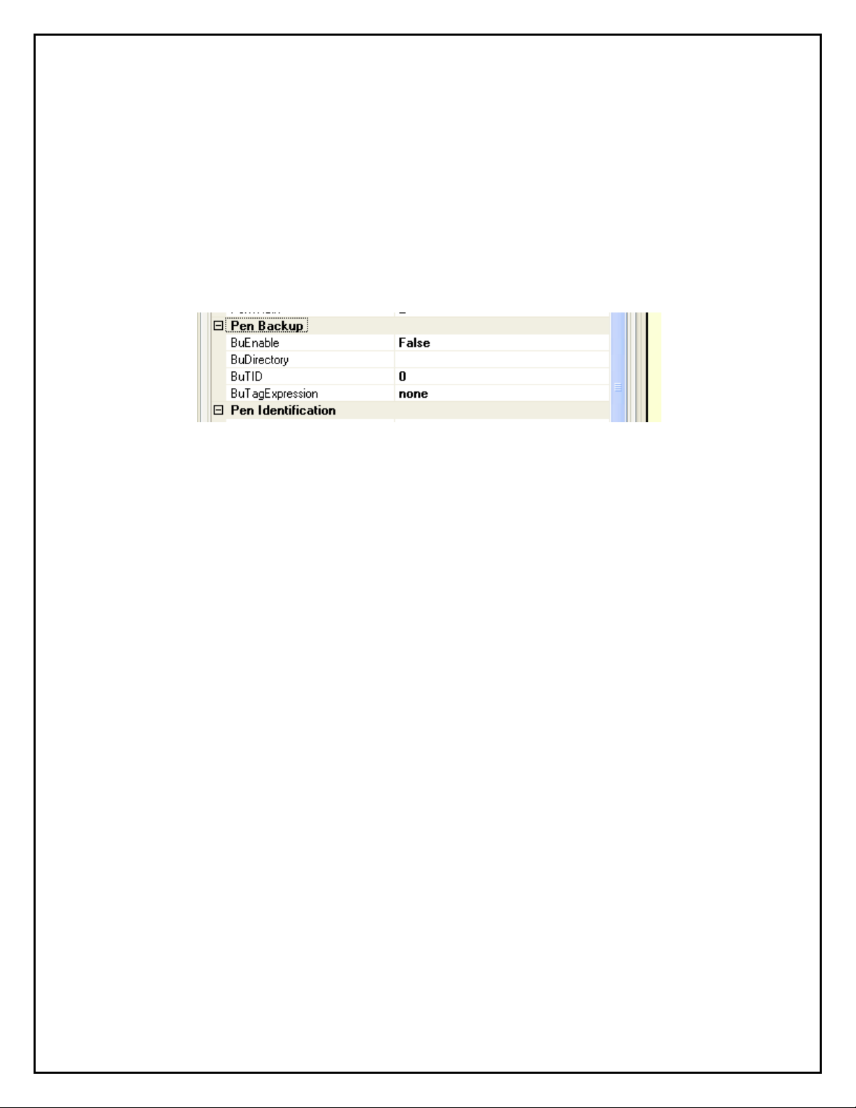
Pen Backup Settings
BuEnable – Enables the use of the backup data source. This is normally false and
must be set to true to use the backup data. This would normal ly only be done when
there is essential missing data. T he Bu Directory, Bu TID and Bu Tag Expression must
be set in order to set BuEnable to true.
BuDirectory - This is the “Alternate Data” directory containing the backup data sour c e.
This directory could be a local directory or a network share. The directory must contain
the intparms.xxx files, the comdata, log and clog subdirectories. The comdata
subdirectory must contain the inttbl.dat file and the log and clog directories must
contain the hourly and compr essed data files as desired.
BuTID - This defines the Backup TID. If the primary TID is based on a Channel/Slot
then this BuTID will be selected from a Tag Selector dialog based on the Alternate data
source. If the primary TID is a derived TID, then this BuTID will be the same as the
primary TID (but using a different ta g expression).
BuTagExpression –If the BuTID is derived, the Expression Editor will be used to
generate the expression. The Expression Editor will use tags from the alternate data
source.
Super Systems Inc. Page 15 of 50 SD Recorder II Operations Manual
Page 16

Chart with red pen missing data and BuEnable false.
Chart with red pen missing data and BuEnable true
Notes on Backup Data
1. Backup directories may be different for each pen.
2. Backup Data will cause some slowdown in r etrieving data.
Super Systems Inc. Page 16 of 50 SD Recorder II Operations Manual
Page 17

Special Pens and the SD Expression Editor
In most cases, Tag values will be plotted directly; however, there will be instances
where you will want to chart values that are derived from one or more tag values.
• When a Pen is a function of a singl e Ta g, simply add the Tag and click on the
“TagExpression” property – this will open the Expression editor with the Tag as a
single variable.
• When a Pen is derived from more than one Tag , it is called a Special Pen. Special
pens are created by clicking on the Special button. Clicking on the
“TagExpression” property for “Special” Pens opens the Expression Editor with a
“Variable Selector”.
The Expression edit or is a tool used to crea te expressions from constants, mathematical
functions and logical functio ns using SDIO Tags as variables,. The expressions can be
tested and evaluated with the editor. When the chart is redrawn, data is retrieved for a l l
tags used as variables in special p ens and the value for each special pen point is
calculated for plotting.
Expression Editor for Tag Pen
(No Tag Selector available)
Super Systems Inc. Page 17 of 50 SD Recorder II Operations Manual
Page 18

Expression Editor for Special Pen
Variable Selector – A Tree view of the
Tag data from which tags can be selected
and added to th e “selected variables” list .
This tree will be a list of the configured
connections, groups and tags.
Selected Variables – A list of variables
that may be used in the special pen's
expression. When using the editor to edit a
previously created special pen, this list will
be initialized with the tags used in t he expression. The value displayed in this list is a
“snapshot” and will change only when t he tag is added to the variable list or when
the “Check syntax and evaluate” button is clicked and the variable is p art of the
expression. A Right click on a row w il l insert the variable into the expression (you
may also double click on the row).
Check Syntax and Evaluate button – Clicking this button will check the syntax
and evaluate the expression. The result will be found in the “Result” box.
Save Expres sion button – Saves the expr ession to the pen's expr essi on.
Expression view box – Displays the expression. You may also edit the expression
in this box.
Result box – Displays the result when clicking “Check Syntax and Evaluate”.
Operators and Constants – Usual math operators.
Logical Operators – Logical operator s alw ays result in 0 if false and 1 if true.
Math Functions – Usual math and trig functions.
Logical Functions
IIF – IIF(x,y,z) is an “if-then-else” construct.
z.
IIF functions can be nested to a depth of 8.
Bit – Bit(x,y) returns 1 if bit y of value x is ON. Otherwise, it returns 0.
Special Functions – SRound is a special rounding function used with load
thermocouple values.
NOTE: In the US, the point is used as the decimal separator; in many other locales,
the comma is used as the decimal separator. When the point is used as a decimal
separator, th e comma is used as a variable separator. When the comma is used as a
decimal separator, the semicolon is used a s a variable separator.
Example: In the US, IIF(t10001>0, 12.5, 9.2) is a valid expression,
while in France the expression would be IIF(t10001>0; 12,5; 9,2)
If x is true then return y else return
Super Systems Inc. Page 18 of 50 SD Recorder II Operations Manual
Page 19

The Chart Area
Legend
Plot Area
Date Time Box
Title
Pen Scale
Note “Historical”
box
The Chart Area is the main displa y. The
interior, called the “plot area” o r “chart
paper” contains the pens, note points, alarm
points, spec limit lines and a curso r .
Surrounding the plot area is the char t
“border area”. The border area contains the
“title” at the top of the chart, a DateTime
box (upper right), a pen “legend” below the
DateTime box, Y axi s “pen scales” on the
right and/or left of the plot area and an X
axis time scale on the bottom of the chart.
The chart area may be in either “RealTime” or “Historical” mode. In RealTime mode,
the border area background is light green.
In Historical mode, the border area is light blue.
When the recorder is in an “online” mode and the
server becomes disconnected, the border area will be
light yellow.
in the Date/Time
Super Systems Inc. Page 19 of 50 SD Recorder II Operations Manual
Page 20

The Cursor and Legend – In RealTime mode (green border), the cursor is not visible
and the legend always displays the current values (right chart edge) of the pens. Rightclicking anywhere in the plot area activates the cursor and places it at the x-axis (time)
clicked. The cursor is displayed with a menu and the values in the legend are the values
of the pens at the x-axis (time) position of the cursor. The chart will automatically go
into historical mode. When drag ged with the mouse, the cursor will move, and the
legend values will follow.
Legend Menu – Right clicking on a pen in the legend will display the legend menu for
that pen.
Hide/Show Pen – The menu will display
“Hide” (pen name) if the pen is currently
visible or “Show” (pen name) if the pen is
currently hidden. Clicking this item will either
hide or show the pen in the plot area. This
can also be done by left clicking on the pen
name. The text for hidden pens will be in
dimmed
italics.
Hide/Show Scale – Clicking this item will hide or show the scale for this pen in the
border area.
Super Systems Inc. Page 20 of 50 SD Recorder II Operations Manual
Page 21

Statistics – C li c ki ng this item will display the
“Pen Statistics” dialog for this pen. This dialog
will display the number of poi nts for this pen in
the plot area. For those points, the minimum,
maximum, average and standard deviation are
calculated and displayed.
Spec Limits – spec limits are normally
specified by some engineering criteria. Lower
Spec Limits (LSL) and Upper Spec Limits (USL)
may be entered here and may be disp l ayed on the chart by checking the checkbox. The
“Calculate” button will calculate limits that will result in CP and CPk of 1.0.
CP and CPk – When Spec Limits are entered, clicking “Calculate” will display values of
CP and CPk based on Spec Limits and the data in the current plot area.
Notes in the P lot Area – Notes are displayed as
points in the Plot Area. Note points are black circles.
When hovering the mouse pointer on or near the
point, the note information will be displayed.
Zooming in the Plot Area – You may zoom in on an area in the plot area by holding
the left mouse button down while dragging the mouse. The zoomed in area will be
outlined. The plot area will be zoomed in on as soon as the mouse button is released. If
the Chart is in RealTime mode it w il l c hange to Historical mode as soon as the chart is
zoomed. Zooming limits are enforced at about 0.1% o f vertical scale and horizontally
at about 5 point intervals.
Super Systems Inc. Page 21 of 50 SD Recorder II Operations Manual
Page 22

Plot Area Menu – When the right mouse button is clicked in the plot area it
repositions the vertical cursor (associated with the legend) and displays the Plot Area
Menu.
Add Note - Opens the “Add Note” dialog. This
menu item will be disabled if the chart's “Note
Mode” setting is set to none.
Un-Zoom – Un-zooms the last zoom operation.
Undo All Zoom – Un-zooms all zoom operations.
View/Edit Note – If the mouse is on or near a
note point, this menu item will appear.
Note:
with a user level of 3 or greater when using
Secure note mode.
Adding or editing a note requires User Login
Chart Control Area
The Chart Control Area is just below the Chart Area and is used to control the Start,
End and Span time of the chart.
Window Width – The width of the displayed plot area expressed in days, hours,
minutes, and seconds. When a chart opens, the char t's Default Window Width is always
used. After the chart is opened, the width may be changed in several ways:
1. By zooming in on the plot area;
2. By editing the width using the time span ed i t editor;
3. By selecting a specific width using the drop down list; or
4. By changing both the start and end times.
Super Systems Inc. Page 22 of 50 SD Recorder II Operations Manual
Page 23

Time Span Editor – The spin buttons
increase or decrease the time span based
on the spin mode. Spin mode can be set by
right-clicking the spin button.
Drop down list – The dropdown list is activated
by clicking on the button. You may then
select a specific time span value.
Start and End
DateTime values –
Start and End values may be chang ed using the dropdown
calendar or editing the DateTime value directly.
Window Width Mode – There are 3 methods for sp eci fying
the window width. The specified mode w i ll control which
inputs are active in the Chart Contr ol area. The mode can be changed in the “Chart
Menu”.
Start Time + Window Width – Start and Window Width inputs are active, End
is not active. This is the default m ode.
End Time + Window Width – End and Window Width are acti ve, Start is not
active.
Start Time and End Time. Start and End are active, Window Width is not
active.
Apply Changes button – There is a button to the
right of the “Time Span Editor” that i s used to apply
changes any time a change is mad e to Start, End, or
Width values. When changes are pending, the button
will be green and enabled. Clicking this button will
cause the chart to refresh with the new values.
Super Systems Inc. Page 23 of 50 SD Recorder II Operations Manual
Page 24

Time slider – Any time data is retrieved, an extra amount of data is called, generally 4
times the amount specified by the window width. This allows you to lo ok additional data
without retrieving more data. The slider indicat es ho w much data there is and what
data you are looking at. The width of the slider indicates the data that has been
retrieved. The width of the slider ba r within the control indicates the data that is being
presented in the plot area. You can drag the slider bar to pan through the currently
retrieved data. You can click on the small arrows at either end of the slider control to
make minor shifts (approximately 1/8th of the data), or you can click on the area
between the bar an d the endpoint arrows to make major shifts (approximately ¼ of the
data).
Scroll Data buttons - T he left (back) and right (forward) data buttons
must be used when th e desired data is not within the current data set. These butt ons
“scroll” the data forward or backward by one window width per click.
RealTime button – The RealTime button places the chart in RealTime mode.
This button will not be active if the chart is in an “alternate” mode or if the server is not
connected.
Chart Scale Selection- When there are hidden chart scales, directly clicking on any
chart scale will cycle through t he undisplayed scales. This enables you to maximize the
chart area and still display another scale when desired.
Super Systems Inc. Page 24 of 50 SD Recorder II Operations Manual
Page 25

Left Pane List Views
The Left Pane is a tabbed control . The Settings tab has been discussed previously; the
other tabs will be discussed here.
The Data and Notes tabs are List views that display information that is synchronized
with the Chart View. The left pane ca n be resized by dragging the panel splitter control.
Data Tab – The Data List view displays all of the points in the
current plot area. The data is synchronized via the cursor. Moving
the cursor in the Chart will cause the row values corresponding to
the cursor to be selected in the list view. Selecting a row of data in
the list view will move the cursor to that time in the chart view.
Notes Tab - The Notes List view displays all of the notes in
the current plot area. Selecting a note in the list view will move
the cursor to that time in the chart view; however, moving the
cursor does not affect the list view.
Super Systems Inc. Page 25 of 50 SD Recorder II Operations Manual
Page 26

Clicking this button
to Edit.
Clicking this button
Alarm Tab - The Alarm List view displays all of the alarms that occurred in the current
plot time span. It is only available in Dat a Center mode. This tab is activated
automatically once the first Ala r m is defined for the chart.
Selecting an alarm in the list view will move the chart cursor to that time in the chart
view; however, moving the cursor does not affect the list view.
Recipe Tab – This tab contains an interactive recipe
application that enables the operator (with the proper security
permissions) to start, stop, and modify any 9xxx recipe
associated with this chart.
All interactivity starts with a user login. Click the
button and the Login screen appears.
Enter your user name and password and
click OK. Your user name will be
displayed where the login button was.
The tab is now active.
will cycle the mode
from Run to Preview
will force a refresh of
the recipe data..
Super Systems Inc. Page 26 of 50 SD Recorder II Operations Manual
Page 27

Run Mode
Right clicking anywhere on the reci pe listing will display a
dropdown list of the following functions when clicked:
Hold Recipe – Causes the recipe to pause at the current
segment elapsed t ime.
Continue Recipe – Allows the recipe to continue.
Advance Recipe – Skips to the next step of the recipe.
Adjust Soak Time – Adjusts the soak time in the recipe.
Stop Recipe – Immediately stops the recipe.
Run Recipe – Opens a dialog box
for entry of the recipe number and
step number if required. When you
click OK the recipe starts
immediately.
Clear Alarm – Acknowledges any pending alarm and
advances the recipe to the next step.
Preview Mode
Right clicking anywhere on the reci pe listing will display a dropdown list of the following
functions when clicked:
Preview Recipe – Opens a
dialog box for entry of the recipe
number.
Clear Alarm – Acknowledges any
pending alarm and advances the
recipe to the next step.
Super Systems Inc. Page 27 of 50 SD Recorder II Operations Manual
Page 28

Edit Mode
The Edit mode enables editing of any recipe residing in the instrument associated with
the current chart as defined as the Default Group in Chart settings. See Page 12.
The editing is limited to setpoint and time values. Step additions, deletions, and
function modifications need to be done using the Instrument Configurator app li cation.
Right clicking anywhere on the reci pe listing will display a dropdown list of the following
functions when clicked:
Run Edited Recipe Once – Immediately starts the edited recipe
once. The edits are not saved.
Edit Recipe – Opens a dialog box for entry of
the number of the recipe to be edited. When
you click OK, the recipe to be edited appears in
the window.
Cancel Edits – Deletes any pending edits and returns the recipe
to its original state.
Save Recipe – Saves the modified recipe to the current recipe
number.
Save Recipe As – Opens a dialog box for entry
of the recipe number to which the edited recipe
is to be saved. When you click OK, the edited
recipe is saved to that recipe location in the
instrument.
Clear Alarm – Acknowledges any pending alarm and advances
the recipe to th e n ext step.
Super Systems Inc. Page 28 of 50 SD Recorder II Operations Manual
Page 29

The Search Tool
The Search Tool is used to search for text in notes or alarms. Enter the text to search
for and the date range to
be searched, and then
click the “Search Notes”
or “Search Alarms”
button. The search
results will be displayed
in the “Search Results”
list. You may then select
a row in the “Search
Results” and “sync” that
item to the chart. When
you “sync” the item, the
chart will refresh with
new data and put the
cursor at the item. If the
Alarms or Notes List view
is opened, it will also be
refreshed.
If the Search All Alarms or the Search All
Notes checkbox is selected, the search
will cover all charts in the database
within the selected date range matching
the search text.
If the note selected is located on a
different chart than that displayed, a
dialog box will be displayed asking if you
want to switch to that chart. If you click
yes, the background chart will update to
the one where that note is located.
Super Systems Inc. Page 29 of 50 SD Recorder II Operations Manual
Page 30

Printing a Cha r t Report
Selecting the Print Setti ngs from the File menu or clicking on the “ P r i nt Setup” icon in
the toolbar will open the “Print Sett ings” dialog.
Printer Settings – Opens a dialog
that allows you to select a printer and
specific printer settings.
Page Settings – Opens a dialog
that allows you to select page
settings including orientation and
margins. For instance, Landscape will
display the chart on the first page
and the notes on the second; Portrait
will display both the chart and notes
on the first page.
Click Preview to view the results of
setting changes.
Report Title and Content – Check boxes that allow you to specify what data is to be
printed in the report. One or more should be checked. Enter a Report title if needed.
Preview – Closes this dialog and opens the preview dialog .
The Print Preview allows you to view
one or more of the pages before
printing. You may print from the printer
icon or exit and print using the menu.
In the following sample a Chart with a
Note and a Notes table are all printed
in the report and the report is in
portrait orientation.
Super Systems Inc. Page 30 of 50 SD Recorder II Operations Manual
Page 31

Exporting Data
The export data tool is used to save configuration and data to an alternate directory
structure for offline use.
You specify the root directory for the a r chive data (there is a browse button available
for this) and check the items you wa nt to include in the archive. You also specify the
date range for the data you want to i nc l ude in the archive. Click the OK button to save
the data (a progress meter will appear while the data is being copied). That data can
then be used offline using an “alternate” mode in the Recorder. (NOTE: Archived data is
not automatically removed from t he c ur r ent data files). There are three principal
reasons for making archive data sets.
1. To archive older data and remove it from
the local computer to increase disk space and
performance. (NOTE: Removing the data is a
manual operation.)
2. To make a data set that can be used
offline at another location (for example, SSi
may request a data set to aid in
troubleshooting a problem you may be
having).
3. To save data and start a new data set
following a major control instrumentation
replacement or upgrade.
Exporting to a CSV/TSV file
This export tool exports the data in the current “Plot Area” of the chart to a csv or tsv
file for use in a text file or more commonly a spreadsheet (for example, Excel).
CSV – Select this for a “comma separated
value” file.
TSV – Select this for a “tab sep arated value”
file.
Data Point Interval – Set the point interval
for exporting the data. The minimum point
interval is one minute. The maximum point
interval is one hour.
Save to File button – opens the Save As
dialog.
Super Systems Inc. Page 31 of 50 SD Recorder II Operations Manual
Page 32

Users
User accounts are required for addi ng and editing notes in SECURE Operating Mode and
for interaction with the Recipe viewer tab. Simple Operating Mode Notes may be added
and edited without a user account.
A user database is m aintained with user names, passwords and user levels. User
passwords must be at least 3 characters long. Passwords may be longer and may
contain numbers. User levels can range from 0 through 99. In this application, the
notes require a level of 3 or greater. User account administration requires a user level
of 10 or greater.
User Login – When you attempt to open “Manage
Users” from the Tools menu, add a secure note, edit a
secure note, or interact with the recipe viewer tab, you
will be greeted with the User Login dialog. Names are
not case sensitive, while pa sswords are case sensitive.
Manage Users - When you select
“Manage Users” under the tools
menu and successfully login, you
will be presented with the “Manage
Users” dialog. In the Manage Users
dialog, you may add or delete
users, assign user l evels and reset
passwords.
User levels are set a s follows:
Levels 0 through 2 - View only.
Levels 3 through 9 - View and Modify.
Levels 10 and over – View, Modify and Manage users.
When a new user is add ed, the password will be set to the user name and must be
changed on that user's first login. The “Reset Password” button also sets the
password to the user name and requires th at user to change his or her password on
next login. The “Show Password” button will reveal the password for the selected user
as long as the mouse key is held down on the button; t h e password replaces the button
text.
Super Systems Inc. Page 32 of 50 SD Recorder II Operations Manual
Page 33

Starting SDRecorderII with Command Line Arguments
SDRecorderII may be started with Command Line Arguments from a command line or
from another application. The following arguments are supported:
• M: (name of configuration to use)
• C: (name of chart to use)
• ST: (start date and time)
• ET: (end date and time)
All arguments are optional and may be used in any order. The following rules apply:
• If any spaces are used, the argument must be en closed in quotes.
• If the configuration (M:) is not used , the current configuration will be used.
• If the chart (C:) is not supplied, the last chart used will be loaded.
• If the ST: and ET: are not supplied, chart starts in RealTime.
• If ST: is supplied and ET: is not supplied, chart starts at ST with Default Window
Width.
• If ET: is supplied and ST: is not supplied, chart starts at ET – Default Window Width.
• If ST: and ET: are supplied, chart starts with ST and Window Width = (ET-ST).
Examples:
• SDRecorderII C:myChart “ST:7/12/2010 10:15” “ET:7/12/2010 13:30”
• SDRecorderII C:myChart “ST:7/12/2010 10:15”
• SDRecorderII C:myChart “ET:7/12/2010 13:30”
• SDRecorderII M:AltSDIO C:myChart “ET:7/12/2010 13:30”
Super Systems Inc. Page 33 of 50 SD Recorder II Operations Manual
Page 34

SDRecorderII Operating Modes
Before loading or creating a chart, the Recorder must know where the data comes from
and what type of data is being used. This information is contained in the “Operating
Mode” file. There can be several operating modes; each can be saved in a named file,
which is an XML file with an extension o f .cfg and will normally be located in the
\SSi\Bin folder. These configuration files may be viewed, created and edited with th e
“SDRecorderII Settings” dialog.
NOTE: When the applicati on is started from a remote computer (for example, started
from a mapped drive) the “Operating Mode” files may not be appropriat e for the local
computer; in this case, a special restric ted Operating Mode is used. These modes are
discussed on Page 37.
Stored Configurations – This drop-down will display a list
of configurations on the local machine. Select one for viewing
in the property windows below. When opening the dialog from
the Options menu, the current configuration in use will be preselected.
Identity – This is the confi guration name and is used to
name the file. The file will name be this name with a .cfg
extension. If you change this name and subsequently save the
configuration, a new file with this name will be created.
Note Mode – There are two modes: Simple and Secure. In
the Simple mode, notes may be added and deleted and there
is no required login to Add/Edit or Delete notes. In Secure
mode, Adding and Editing notes requires a login and deleting
notes is not permitted. This setting requires a Login to be
changed.
Operating Mode - The information required in the lower
property box is dependent on the “Operating Mode” selected.
This mode should always be set before proceeding to the
lower box.
SDRecData
Online connects to a “Server” to get real time and historical
data.
Alternate gets data from an archive location – data is offline
and there is no server.
Note: Chart display, control and operations are the same for
all Operating Modes with one exception: “RealTime” operation
is not available in “Alternate” modes (historical data only).
SDRecMode – either Data Center or SDIO
Super Systems Inc. Page 34 of 50 SD Recorder II Operations Manual
Page 35

Operating Mode Details
Mode: SDIO – Online
Server – Specify Localhost or Server IP Address or
DNS Name.
Chart FilePath – Specify the directory that will
contain the Chart Files; this may be on the local
machine or on a remote computer.
Clog Path – Specify the directory containing the
compressed log files.
ComPath – Specify the director y c ontaining SDIO's
communication files (for examp l e, inttbl.dat,
msgtbl.dat, etc.).
ConfigPath – Specify the config directory for SDIO.
LogPath – Specify the directory contai ning the SDIO
hourly log files.
NoteDB – Specify the path and filename for the
Notes Database.
Mode: SDIO – Alternate
DefaultDir – Specify Directory for the Archived
data.
Clog Path – Specify the directory containing the
compressed log files.
ComPath – Specify the director y c ontaining
SDIO's communication files (for exa m ple,
inttbl.dat, msgtbl.dat, etc.).
ConfigPath – Specify the config directory for
SDIO.
LogPath – Specify the directory contai ning the
SDIO hourly log files.
NoteDB – specify the path and fil ename for the
Notes Database.
Super Systems Inc. Page 35 of 50 SD Recorder II Operations Manual
Page 36

Mode: Data Center – Online
Server – Specify Localhost or Server IP
Address or DNS Name for remote
connections.
Chart FilePath – Specify the directory
that will contain the Chart Files – this may
be on the local machine or on a remote
computer.
SqlInstance – Specify the path to the
database instance.
Normally localhost\SQLEXPRESS.
UseAccessNotesSDB – Specify either
True or False. In most cases this wil l be set
to false when using DataCenter mode.
Mode: Data Center – Alternate
DefaultDir – Specify Directory for the
Archived data.
ChartFile Path – Specify the directory
containing the archived chart files.
SDHFilePath – Specify the directory
containing archived
compressed data files.
ConfigTree – Specify the path to the
archived configtree.cfg file.
SqlInstance – Specify the path to the
database source. Normally, this is
localhost\SQLEXPRESS.
SSiDataDB – Specify the path and
filename for Data Center hourly Ta g Database.
Super Systems Inc. Page 36 of 50 SD Recorder II Operations Manual
Page 37

Restricted Operating Modes
Normally, SDRecorderII will be started from the local computer and will have operating
mode files specific to that computer. SDRecorderII can be installed from a network
drive or mapped drive. The operating mode files on the remote location may not be
appropriate for use on the local computer.
These restricted modes are primarily intended for use with legacy SuperDATA
applications. In the SuperDATA RealTime/RealEdit HMI, applications normally reside
only on the server and, when used at a workstation, are started from a drive mapped to
the server. Any time SDRecorderII is started from a network drive or a mapped drive,
it will use a restricted operating mode.
There are only two restricted Operating Modes: RealTimeSDIO and RealTimeDC. These
operating mode files will alwa ys r esid e in the application directory on the server.
When used on a workstation, Rea l TimeSDIO is modified based on the workstation's
SDIO.ini file.
When used on a workstation, Rea l TimeDC is modified based on the Server Name.
When operating in a restricted mode, the Options menu will be hidden, and you will not
be able to change Operating modes.
Limiting Operating Modes - Examples
SDRecorderII may be set to limit operation to SDIO mode or DC mode. When installed
as SDRecII for SDIO, SDRecII will default to use only SDIO Operating modes. When
installed as DataCenter or DataCenter Client, SDRecII will default to using both SDIO
and DC modes. These limitations can be changed at any time by running SDRecII from
the command line with the MA: opt ion as follows:
• To limit SDRecII to SDIO run: SDRecorderII MA:SDIO
• To limit SDRecII to DC run: SDRecorderII MA:DC
• To remove limits run: SDRecorderII MA:BOTH
Super Systems Inc. Page 37 of 50 SD Recorder II Operations Manual
Page 38

Using Automatic Update Feature
If there are no Up dates newer than the versio n
When an update is available you ar e offered
later time. To install now, click Yes.
Updates for SDRecorder II are posted regularly on the Super Systems fil e server and
are available at no charge to all registered users.
Note: You must have internet access to use Automatic
Update.
To access the updates, click on the Help menu item and
select Check for Updates.
on your computer, the notice will appear as
shown on the left. Click OK to return to
SDRecorder II.
the option to install the update no w or at a
If upgrading from:
• SDRecorderII in
down any data center apps running from that directory (locally or on remote
computers). NOTE: It will not be necessary to shut down SDCMaster or
SDCConfig as they will not be up graded.
• SDRecorderII in
any other instances of SDRecorderII from that directory (locally or on remote
computers). NOTE: It will not be necessary to shut down SDCMaster or
SDCConfig or any other DataCenter apps.
During the update process, a progress screen is display ed.
SuperSystems\ bin
SSi\ Bin
directory (SDRecII for SDIO upgrade): Shut down
directory (SDCClient upgrade): Shut
Upon completion of the update, SDRecorder II will return to its original stat e with the
updates installed. Restart any instances of SDRecorder II running on mapped
workstations.
Super Systems Inc. Page 38 of 50 SD Recorder II Operations Manual
Page 39

Appendix
Batch System Option
The Batch option adds a system to keep track of batch loads in an SQL database, link those
loads to historical load charts, and provide load reports.
Installation of the Option
SDRecorder II ships with the Batch Option code installed. It simply needs to be activated.
Activation of the Batc h O pti on
To activate the Batch Load Tracking option, click on the Help
menu item and select About.
You will be presented with the SDRecorder II About
window.
Click on the Activate button.
A Login box will appear. Enter your
User Name and Password and click
OK.
If you want to activate the batch tracking system for a 30
day trial period, contact Super Systems sales department for
a temporary license code.
If you purchased SDRecorder II with the batch tracking
option, refer to the software package for the license code.
Enter the license code you received from Super Systems and
click OK.
The Batch menu item and Batch Icons will appear at the top of your SDRecorderII window.
Super Systems Inc. Page 39 of 50 SD Recorder II Operations Manual
Page 40

Configuration of the Database
Tabs along the top separate the
five tables of the database.
These buttons allow you to add
The first time you use the database you will want to configure the record headers, (Titles), as
you wish them to appear in the data display screens and reports.
From the Batch menu select Batch Administrator and then
Configure Database.
A Login box will appear. Enter your User Name
and Password and click OK.
You will be presented with the Configure Batch System window.
• The Name column contains
the internal, default title of
the record.
• The Caption column contains
the custom title of the
record. This is the only field
you can edit.
• The Type and Length
columns are fixed and are
shown only for informational
purposes.
To add a custom title to a column, double click the Caption field.
Repeat this process for all the column titles you want to customize in all the tables.
When finished, close the configuration window by clicking on the Red “X” in the upper right
corner of the window.
Super Systems Inc. Page 40 of 50 SD Recorder II Operations Manual
optional columns to the table.
The Edit Caption box will open. Enter the new caption
and then click OK. The new caption will appear in the
table.
Page 41

Adding System Data
The next step is to populate the database with Furnace, Part and Customer data.
Furnace Data
From the Batch menu, select Batch Administrator and then Add/Edit Furnaces.
A Login box will appear. Enter your User Name and Password and click OK.
You will be presented with Add/Edit Furnace Table window.
For each furnace, enter the name, channel,
and instrument type, and check the Active
checkbox to establish communications.
Part Data
From the Batch menu, select Batch Administrator and then Add/Edit Parts.
A Login box will appear. Enter your User Name and Password and click OK.
You will be presented with the Add/Edit Part Table window.
For each Part, enter the name, Recipe, P a r t
Weight, and Weight Units, and check the Active
checkbox to indicate Par t is used presently.
Super Systems Inc. Page 41 of 50 SD Recorder II Operations Manual
Page 42

Customer Data
From the Batch menu, select Batch Administrator and then Add/Edit Customers.
A Login box will appear. Enter your User Name and Password and click OK.
You will be presented with the Add/Edit Customers Table window.
For each Customer, enter the name and check
the Active checkbox to indicate the Customer is
currently valid.
Super Systems Inc. Page 42 of 50 SD Recorder II Operations Manual
Page 43

Using the Load Tracking System
Tabs used to select the displa y of New, Current,
Dropdown Furnace pick list t o select to
furnace.
New Batch Loads
From the Batch menu select New Batch Loads.
A Login box will appear. Enter your User Name and Password and click OK.
You are presented wit h the New Batch Load s window.
display either all pending new loads or
only those destined for a particular
Historical, Searched or Inactive load data. Tabs with
restricted access will be grayed out if the user priority is
lower than what is required.
Start the load entry pro cess by clicking the New Load tab.
The New Batch Loads screen will open.
From the Furnace dropdown list,
select which furnace the load is to
be processed.
Super Systems Inc. Page 43 of 50 SD Recorder II Operations Manual
Page 44

Select the Customer and Part from the dropdown lists provided.
Enter the Batch ID number, Quantity of parts, and Shop Order
number. The Add button should be activated, indicating that all the
required information is complete. Review your entries for accuracy
and, if correct, click on the Add button to register these parts in the
Batch Load.
Additional parts can be added to the Batch Load by
repeating the above pr o cess . There is no limit to the
number of different parts in a load. If the recipe for
the added part is different than the first part added to
the load, then an alert box will open, requesting a
supervisor’s approval for the part’s inclusion.
When you are finished entering parts to the load,
click the Save and Start Load button if you are
going to immediately charge the load into the
furnace.
If it will be some time before you charge the load
into the furnace, then click the Save Load button.
The Batch will be added to the New Load queue for
later processing.
When you do load the Batch into a furnace
immediately select t ha t load r e co rd and click the
Start Load button to inform the program when the
load started processing. That
load will now be part of the
Current Loads listing and a note
will be added to the chart record.
You may queue up as many loads as you wish. In fact, you can use this as a simple production
scheduler.
Super Systems Inc. Page 44 of 50 SD Recorder II Operations Manual
Page 45

Supervisors Only
If for some reason a queued load needs to be
modified, you can right
popup menu will appear. Click on Make Load
Inactive. This will change the load records status to
inactive.
All inactive loads are accessible to supervisors only
by clicking the Inactive Loads tab.
click on the load record and a
Supervisors may modify any inactive load record
within limits. For instance, a change to the number
of parts in the load requires that the total part
weight field be updated to refl ect the effect of the
new part count.
When all adjustments to the load record are completed, click on the Save button. The edited
load record will be returned to its original location.
Super Systems Inc. Page 45 of 50 SD Recorder II Operations Manual
Page 46

Current Batch Loads
When you click on
The Sync to Chart button
the Current Batch
Loads tab you are
immediately
Presented with
the Current Loads
Screen. Everyone
can access this
screen.
opens the chart for the
selected furnace and
adjusts the chart start
time to correspond to
the time in value.
If you are logged in as a Supervisor or Operator (permission level 3 or higher),
an additional button Mark Load Completed is revealed. When the furnace
cycle is complete and the load is out of the furnace, click the Mark Load
Completed button. The load record TimeOut field will be completed, and the
load record will be trans ferre d to the Load History records.
Super Systems Inc. Page 46 of 50 SD Recorder II Operations Manual
Page 47

Batch Load History
Use the drop down list to
Select the date range
The Load Report
Sets which printer to use,
options.
Sets the page layout
Use this selector to edit
appear on the report.
Edit the report title and
by checking the boxes
Click on the Preview
on the screen.
When you click on the Load History radio button, you are immediately presented with t h e
Current Loads Screen. Every one can access this screen.
The screen opens, displaying all loads from all furnaces completed in the last seven days.
select loads from either
all furnaces or one
particular furnace. The
load list will update
immediately.
desired using the date
picker boxes
button is used to
generate a load report
for the selected load
When the Load Report button is clicked the Print Settings dialog box opens.
its configuration and
select the report content
which customer’s parts
button to view the report
configuration and
options.
Super Systems Inc. Page 47 of 50 SD Recorder II Operations Manual
Page 48

The following is a sample of the print preview window. You may print a hard copy directly from
the preview. Hint: If you do not have access to a color printer, you may print to a PDF file
printer and email the report to interested parties.
Super Systems Inc. Page 48 of 50 SD Recorder II Operations Manual
Page 49

Searching Loads
The Batch Loads screen contains a tab for “Search Loads”. This
view displays all loads that satisfy the current search criteria. If
no search criteria have been set, the view will be empty. Search
criteria are set with the Search Criteria dialog – opene d by right
clicking on any load
screen and selecting the
“Search Loads” menu
item from the context
menu or by clicking on
the Search Icon in
the upper right corner of the window.
The Search Criteria dialog allows you to build complex search
conditions. Each condition has a drop-down selector. The
selector contains some special key words and database values.
Keywords
Any – any value is
acceptable.
Like – any value that
satisfies the “like” specification is acceptable.
Range – any value within the specified
date range is accepta ble.
A drop-down may also contain a specific value—for example, a
Furnace, a Part or a Customer. When a specific value is
specified, only records satisfying that condition will be returned.
Like conditions – When a like
condition is selected, a text box is
supplied to specify the condition.
Conditions are specified using characters and wildcards. The “*”
wildcard specifies a string of any characters and a “?” specifies
any single character. (conditions are not case-sensitive)
Examples:
• *e * - any customer that has an
• E* - any customer whose name begins with an
• * Inc – any customer that ends in
Inc.
• e???shop – any customer that has e characters followed by
metshop, etc).
Compound Conditions – When multiple conditions are set, they are combined.
Search conditions persist. Any time you open the Search Criteria dialog, the previous search will be set and you can
add, remove or modify those conditions. When the Batch Loads screen is closed, the search conditions are cleared.
e
.
shop
(for example, TheShop, OneSh o p,
e
in the name.
Super Systems Inc. Page 49 of 50 SD Recorder II Operations Manual
Page 50

Revision History
Rev.
Description
Date
MCO #
-
First Release
02/26/2012
2097
A
Chart Scale Selection added
Text and layout changes included
09/12/2012
N/A
B
Content for SDIO and SDC versions of software combined
Additional functionality updates
06/10/2013
2126
New Decimal note added
into one manual
Super Systems Inc. Page 50 of 50 SD Recorder II Operations Manual
 Loading...