

Page 1

Operations Manual
PGA 3000
Portable 3-Gas IR Analyzer
Please read, understand, and follow these instructions before operating thi s equipment.
Super Systems, Inc. is not responsible for damages incurred due to a failure to comply with these
instructions. If at any time there are questions regarding the proper use of this analyzer, please
contact us at (800) 666-4330 for assistance.
7205 Edington Drive
Cincinnati, OH 45249
513-772-0060 800-666-4330
Fax: 513-772-9466
www.supersystems.com
SSi Manual 4549 Page 1 of 16 3-Gas Analyzer PGA3000
Revision Level E
Page 2

Table of Contents
PGA 3000 Operating Instructions...................................................................................................... 3
Introduction........................................................................................................................................... 3
Specifications........................................................................................................................................ 3
Basic Operating Theory ..................................................................................................................... 4
Analyzer Start-Up Procedure........................................................................................................... 4
Filters ....................................................................................................................................................... 5
Condensation / Moisture .................................................................................................................. 5
Battery..................................................................................................................................................... 5
Menu List................................................................................................................................................. 6
IR Status Display – Menu Page 1................................................................................................... 7
IR Overall Status Display – Menu Page 2 ................................................................................... 7
Combustion Display – Menu Page 3.............................................................................................. 8
Pump Control - Menu Page 4........................................................................................................... 8
Set Display Values – Menu Page 5................................................................................................. 8
Help Page - Menu Page 6.................................................................................................................. 9
Calibration Dates and Run Times - Menu Page 7..................................................................... 9
About/Sign-On – Menu Page 11................................................................................................... 10
Start logger – Menu Page 12......................................................................................................... 10
Logged Data File – Menu Page 13 ............................................................................................... 11
Zero Calibration – Menu Page 14................................................................................................. 11
O2 Cell Calibration – Menu Page 15............................................................................................ 12
Port Setup - Menu Page 21 ............................................................................................................ 12
Set The Date and Time - Menu Page 22..................................................................................... 12
Data Set Page - Menu Page 23 ..................................................................................................... 12
Span Calibration – Menu Page 24................................................................................................ 13
Set Pass Codes - Menu Page 25.................................................................................................... 13
Clear Logged File - Menu Page 26............................................................................................... 13
Typical diagnostic uses: .................................................................................................................. 14
Spare Parts........................................................................................................................................... 15
SSi Manual 4549 Page 2 of 16 3-Gas Analyzer PGA3000
Revision Level E
Page 3

PGA 3000 Operating Instructions
Introduction
The Model PGA3000 is a portable 3-Gas IR analyzer with an Oxygen (O2) cell onboard. It measures Carbon Monoxide (CO), Carbon Dioxide (CO2) and Natural
Gas (CH4) typically found in an endothermic atmosphere.
Specifications
The unit is designed and manufactured for the atmosphere heat-treating
industry.
CO range: 0.00 to 30.00 %
range: 0.000 to 2.000 %
CO
2
range: 0.00 to 15.00 %
CH
4
range: 0.01 to 25.00%.
O
2
Sampling method: Extraction by internal pump (when necessary)
Accuracy and repeatability: ± 1% of full scale
Flow Meter: Inside case lid and also on-screen
Pump Operation: On/Off/Automatic
Power: 115/230 VAC - 50/60 Hz – 60 Watts
(Rechargeable Battery Power)
Data Retrieval: Up to 4 gases - 10 Furnaces/Generators
500 minutes/furnace
Data collection review on PGA3000 screen or
Upload to Microsoft EXCEL
Operating Temperature: 32° to 122° F (0° to 50° C)
Dimensions: Approx. 16”H X 20”L X 8”D
Weight: Approx. 30 lbs.
SSi Manual 4549 Page 3 of 16 3-Gas Analyzer PGA3000
Revision Level E
Page 4

Basic Operating Theory
The Model PGA 3000 has been designed for the simultaneous analysis of CO,
CO2 and CH4 in heat-treat furnace atmosphere gases. It has a 16 line by 40character LCD display and a 4 x 4 keypad for the operator interface. Information
is presented to the operator on various screens. The operator selects the
appropriate page and enters the number using the keypad.
Numeric keypad key assignments.
0 – 9 are used to enter numeric data.
* is the escape key and clears all numbers previously entered.
# will display a specific menu, to select a specific page, press a numeric key (or
two numeric keys) and then the # key.
A is used as the ENTER key.
B moves the cursor up.
C moves the cursor down.
D adds a decimal point to the data being entered on a screen, also toggles from
one furnace to the next on the data collection page.
Analyzer Start-Up Procedure
Turn the power switch on and allow the instrument to warm up until numbers
appear on the default screen instead of ********. This process should take
approximately two minutes.
Accurate readings are only possible if the sample is taken from a clean (free of
excess carbon buildup) sample port. The current state-of-the-art technology
associated with IR sampling requires that a clean, soot free sample be available
for analysis. A clean sample port will also increase the life of the filter elements,
and reduce the possibility that soot will enter the unit and contaminate the
sensors.
On a furnace, the ideal port would be found on SSi’s Sample Port (Part Number
20263). If this is not available, the burnout port of a freshly burned-out Gold
Probe™ would be an alternative, although this would still contain a trace amount
of soot.
On a generator, a dedicated sample port should be available. This sample port
should be blown out before it is used, which will remove any soot that has
accumulated in the line. This is accomplished by opening the valve without
connecting the analyzer. Wait until the gas stream is clean before proceeding
and connect the sample line to the sample port.
SSi Manual 4549 Page 4 of 16 3-Gas Analyzer PGA3000
Revision Level E
Page 5

The ideal flow rate for sampling should be between 1.0 and 1.5 Standard Cubic
Feet per Hour (SCFH). A visual indication of flow rate can be obtained through
the mini flow meter located on the inside of the lid of the case, or by the digital
flow meter on the left side of the display. The flow meter on the inside of the
case also contains a dial that allows the user to restrict the flow if necessary to
maintain an appropriate flow rate. If the sample gas is not under pressure, the
internal pump can be used to extract it. The internal pump can be operated
manually, or it can be turned on or off automatically when it detects low sample
flow.
Filters
There are two filters that are intended to prevent soot or other contaminants
from entering the unit. The first is an in-line filter that is located at the end of
the sample tubing assembly. The second is a bowl filter located on the inside of
the lid. Periodic inspection of these filters will ensure smooth operation. When
new, the elements in both of these filters are white. Both are oriented in the
sample stream in a manner that causes any contaminants to collect on the
outside of the filter media, which allows for a visual inspection of filter status.
Condensation / Moisture
When a hot gas is cooled rapidly, moisture in the gas can condense and form
water. This water can collect in the sample tubing assembly, and eventually
enter the bowl filter. Care must be taken to ensure that no water enters the
unit, as this will cause permanent damage to the sensors. The unit should be
closely monitored during operation to determine if moisture is collecting in the
bowl filter. If this is the case, the bowl filter basin can be removed and emptied
by unscrewing it. Although water in the bowl filter will not cause damage to th e
unit, this filter is not intended to be used as a condensation receptacle. If
moisture has collected in the bowl filter, sampling should be stopped, and steps
should be taken to prevent this from occurring before operation is resumed.
Battery
The battery in the PGA3000 in intended to provide more than enough power to
operate the unit continuously for an eight-hour shift. When
Battery Low
is
displayed on the LCD screen, the unit is in need of a charge. To charge the
PGA3000, plug it into a 110 or 220VAC power source using the supplied power
cord. The LED above the power cord input is red while the unit is being charged,
and it will turn to green when charging is complete.
For maximum battery life, do not recharge the battery after each use unless the
Battery Low
message appears on the screen. Reducing the number of times that
the unit is charged will maintain the battery’s original storage capacity for a
longer period of time.
SSi Manual 4549 Page 5 of 16 3-Gas Analyzer PGA3000
Revision Level E
Page 6

Menu List
The menu list shows the available pages displayed six at a time. The cursor up
(B) and the cursor down (C) keys are used to scroll the list.
OPERATOR MENU
1. IR STATUS DISPLAY
2. IR OVERALL STATUS DISPLAY
3. COMBUSTION DISPLAY
4. PUMP CONTROL
5. SET LCD DISPLAY (CONTRAST/BRIGHTNESS) VALUES
6. HELP
7. CALIBRATION DATES
11. ABOUT/SIGN-ON
12. START LOGGER
13. LOGGED DATA FILE
14. ZERO CALIBRATION
15. O2 CELL CALIBRATION
CONFIGURATION MENU – Pass code required
21. PORT SETUP
22. SET THE DATE AND TIME
23. DATA SET PAGE
24. SPAN CALIBRATION
25. SET PASS CODES
26. CLEAR LOGGED FILE
Pages number 8, 9, 10, 16, 17, 18, 19, 20 do not exist. The Configuration Menu
pages require the entry of a pass code to access them. The menu list page
shows the date and time at the bottom of the screen.
Pressing the # key allows the user to review the menus at anytime.
Screens 1 through 20 do not require any security codes. Screens 21 and higher
are configuration screens, and a pass code is required. The default pass code is
1, however this can be changed to any number between 0 and 512 by accessing
Menu Page 25.
SSi Manual 4549 Page 6 of 16 3-Gas Analyzer PGA3000
Revision Level E
Page 7

IR Status Display – Menu Page 1
The IR Status Display
shows the current
readings of CO, CO2
and CH4. Also shown
is the relative flow rate
of the sample by a fuel
gauge on the left-hand
side of the screen.
The sample pump may
be turned on or off by
pressing the A key.
IR Overall Status Display – Menu Page 2
The IR Overall Status
Display shows measured
values and calculated
values, and allows entry
of data for the
calculations. The
operator can enter the
furnace temperature,
probe millivolts, probe
temperature, and either
the CO Factor or the
Process Factor. The probe calculations will be based on which value was entered
last (i.e. COF or PF). An * after the data values indicates which value is used in
the calculations. The equivalent value of the other value is computed and
displayed. For example if the probe millivolts is 1100, the probe temperature
1650 and the COF is 200, then the probe %C is calculated as 0.51% and the
equivalent PF is calculated as 143. From the three gases and the furnace
temperature the IR %C and equivalent millivolts is computed. The IR %C and
the probe %C are used to compute suggested COF and PF values. Data values
are changed by using the cursor keys (B and C) to highlight the value and then
entering the new value followed by the A key. Suggested COF or PF can be
entered in your control instrumentation so that the %C calculated from the
carbon probe readings will be the same as the %C calculated by the IR 3-Gas
readings.
WARNING – Large changes should be verified by shim stock analysis.
SSi Manual 4549 Page 7 of 16 3-Gas Analyzer PGA3000
Revision Level E
Page 8
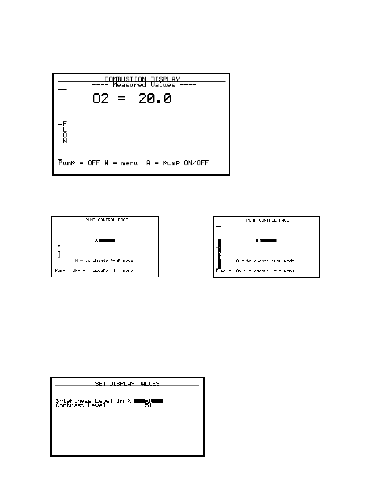
Combustion Display – Menu Page 3
Pump Control - Menu Page 4
The combustion display
shows the current reading
in % excess oxygen. Also
shown is the relative flow
rate of the sample by a
fuel gauge on the lefthand side of the screen.
The sample pump may be
turned on or off by
pressing the A key.
The pump control page is used to set the pump mode. The sample pump mode
can be changed from OFF to ON to AUTO by pressing the A key. Auto mode will
turn the pump on when the flow is below approximately 1.5 SCFH and off when
it is above approximately 1.5 SCFH. Also shown is the relative flow rate of the
sample by a fuel gauge on the left-hand side of the screen. There is also a
traditional flow meter located in the lid of the PGA. Although the flow indicator
on the screen has been calibrated at the factory, the most accurate flow
measurements should be taken with the flow meter inside the lid.
Set Display Values – Menu Page 5
This page is used to adjust the
display backlight brightness and
the contrast. The values
entered range from 0 to 100.
SSi Manual 4549 Page 8 of 16 3-Gas Analyzer PGA3000
Revision Level E
Page 9

Help Page - Menu Page 6
Calibration Dates and Run Times - Menu Page 7
This page can be used
as a reference to show
the functions of the
various buttons on the
keypad.
The same information
has also been included
on the laminated
reference sheet that has
been attached inside the
lid of the PGA.
This page shows the
most recent calibration
dates, as well as the
amount of time that has
elapsed since each
calibration. Time is
shown in hours and
minutes.
These dates do not need
to be set after calibration
since they will be set
automatically whenever
a calibration is
performed. NOTE: For the correct calibration dates to be entered, the internal
clock must be set correctly (see page 22).
SSi Manual 4549 Page 9 of 16 3-Gas Analyzer PGA3000
Revision Level E
Page 10

About/Sign-On – Menu Page 11
This page is the sign on
screen that shows the
SSi logo, address, and
phone number. Also
shown are the firmware
version number, the
unit serial number, and
the date of the last
factory calibration.
Some units will also
show the internal
temperature of the unit.
Start logger – Menu Page 12
This page is used to
name and store a data
log file. The PGA3000 is
capable of storing 10
tests (files) of 500
minutes each. To start
storing data, first select
a test number, 0 – 9.
This specifies the
storage location (file) of
the data. Then input a
name and then an ID number. The name selected from the list at the bottom of
the page by number (0 – 9). The ID number is any value from 0 to 999. Then
cursor down to the Stop/Run then select and press the A key to start or stop
storing data. STORING DATA will appear near the bottom of the screen
whenever the data logging is active. Only one test number can be active at a
time. If the test number is changed and started, then the previous one is
stopped. When a test is started, all previous data in that test is cleared. See
Basic Operating Theory (page 4 of 15) for keypad key assignments.
SSi Manual 4549 Page 10 of 16 3-Gas Analyzer PGA3000
Revision Level E
Page 11

Logged Data File – Menu Page 13
This page displays the
logged data ten points
at a time. When the
page is first entered, it
displays the most
recent test number and
the data point. The
starting number of the
data points displayed
can be changed either
by the cursor keys (B
= up. C = down) or
entering a point number and pressing the A key. Entering a number and pressing
the D key or simply pressing the D key to sequence through the tests can
change the test number displayed.
Zero Calibration – Menu Page 14
This page is used to zero the IR
cells. It is very important to be
sure that the sample gas is a
good zero especially for CO2.
Air has approximately 0.08%
CO2 and required a CO2
scrubber (See Spare Parts List).
WARNING: If using the CO2
scrubber, the source of air
should be from outside the
facility, not air from within
the facility.
the PGA3000. The sample gas flow rate should be between 1 and 1.5 SCFH.
Pressing the A key will start the zeroing process, which could take up to 4
minutes. If the flow rate is too low then an error page will appear and the cells
will not be zeroed. If any of the readings of the cells are greater than 10% of
nominal range, then a range error page will appear. This is a WARNING and it is
recommended that the zero gas be checked before proceeding. Pressing the A
key will bypass the range error and begin the zeroing process. If any of the
readings of the cells is greater than 20% of nominal range, then a FACTORY
CALIBRATION REQUIRED message will appear near the bottom of the screen
and the calibration is inhibited. A zero complete page will appear when zero
calibration is finished.
It is recommended that 99.9% pure nitrogen be used for zeroing
WARNING: Do not pressurize PGA3000 with
SSi Manual 4549 Page 11 of 16 3-Gas Analyzer PGA3000
Revision Level E
Page 12

compressed gas. Always start the flow of Nitrogen and regulate prior
to connecting to PGA3000 inlet.
O2 Cell Calibration – Menu Page 15
This page is used to
calibrate the oxygen
sensor. The oxygen
sensor is calibrated
using air (20.9% O2) as
the reference. If the
oxygen cell output is
outside of a 30% band
then the message
REPLACE O2 CELL! will
appear near the bottom
of the screen. When
calibrating the O2 sensor, turn on the pump and calibrate using air span only.
Pressing the A key will begin the calibration process. A calibration complete page
will appear when calibration is finished.
Port Setup - Menu Page 21
This page is used to set the parameters for the RS 232 port on the DB-9
connector. The baud rates are set by entering a number from 0 to 7 baud
rates of 1200 to 38400 (1200, 2400, 4800, 9600, 14400, 19200, 28800,
and 38400). Entering a number 0 to 2 can change the RS 232 mode. 0 is
the dump/minute mode, 1 is Modbus, and 2 is terminal mode.
The default setup is: 19200 Baud rate, MODBUS
Set The Date and Time - Menu Page 22
This page is used to set the internal clock/calendar. Select a number that
you would like to change by using the B and C buttons. Then type in the
number and press A to enter this number. No changes will take place
until the seconds are set, which starts the clock under the new settings.
Numbers 1 through 12 change the month. The days of the week are
entered using 0 for Sunday and 6 for Saturday. Hours are entered in 24hour format, i.e. 8 for 8AM and 14 for 2PM.
Data Set Page - Menu Page 23
This page allows for the entry of data that the operator should not
normally access. At this time the only data value is the IR shim factor
used in calculation the % carbon. Normally this value should be 150.
However furnace conditions, measured by shim stock tests, may require
changing this value.
SSi Manual 4549 Page 12 of 16 3-Gas Analyzer PGA3000
Revision Level E
Page 13

Span Calibration – Menu Page 24
This page is used to
span the IR cells. It is
very important to be
sure that the sample
gas is certified and
within the noted
specifications. Using the
B key, cursor up to the
value of each gas and
enter the value
displayed on the
certified tank. The
sample gas flow rate should be between 1.0 and 1.5 SCFH. Pressing the A key
will start the spanning process. Note that the spanning process could take up to
3 or 4 minutes. If the flow rate is too low, then an error page will appear and the
cells will not be calibrated. If any of the cell readings is greater than 10% of
nominal range, then a range error page will appear. This is a WARNING and it is
recommended that the span gas and entered values be checked before
proceeding. Pressing the A key will bypass the range error and begin the
calibrating process. If any of the readings of the cells is greater than 20% of
nominal range then a FACTORY CALIBRATION REQUIRED message will appear
near the bottom of the screen and the calibration is inhibited. A Span Complete
page will appear when calibration is finished.
For maximum accuracy, the values of the span gas should be approximately
20%CO, 1%CO2, and 5%CH4. The farther the gas value is from these nominal
values, the less accurate the calibration will be.
Set Pass Codes - Menu Page 25
This page is used to change the pass code for Menu Screens 21 and
higher. The default setting is 1, however this can be changed to any
number between 0 and 512.
Clear Logged File - Menu Page 26
This page is used to clear the data-logged data. Select the test number to
clear. Then cursor down and press the A key to clear the data. Since the
data log file is cleared whenever a test is started, it is usually not
necessary to use this page. The new data will over-write the existing
data.
SSi Manual 4549 Page 13 of 16 3-Gas Analyzer PGA3000
Revision Level E
Page 14

Typical diagnostic uses:
Why a 3-Gas IR Analyzer for atmosphere diagnostics?
The PGA3000 Analyzer measures CO, CO2, and CH4. Carbon potential can be
calculated using furnace temperature and the relationship of these 3-gases.
Oxygen probe real-time measurement of the furnace atmosphere can be verified
by 3-Gas analysis.
In addition to being an excellent diagnostic device, the PGA3000 will provide the
necessary data to fine-tune your atmosphere control.
Data retrieval: RS232, 9-Pin connector (included), Export to MS Excel via Upload
Utility Software (included)
Endothermic Generator Diagnostics
♦ The effectiveness of the catalyst is measured by the CH4 content. Less than
0.5% is an indication of properly functioning catalyst. Higher concentrations
indicate the necessity for either conditioning or replacement.
♦ Measuring the level of CO in the carrier gas allows correction of the % carbon
reading at the furnace.
Heat Treat Furnaces – Conventional Endo Gas
♦ Furnace atmosphere carbon potential (% C) can be verified with the
PGA3000.
♦ Measuring carbon monoxide (CO) and carbon dioxide (CO2) can show
possible problems (i.e. water leaks, air leaks, and radiant tube leaks).
♦ The PGA3000 measures the free methane (CH4) in the furnace atmosphere.
Heat Treat Furnaces – Nitrogen/Methanol Endo Gas
♦ The carbon monoxide (CO) level in the furnace atmosphere indicates the
effectiveness of the cracking of the methanol. Equilibrium of this reaction
CH3OH Æ CO + 2H2 is temperature dependent.
Heat Treat – Oxygen Sensor Control
♦ Periodic verification of the performance of oxygen probes.
SSi Manual 4549 Page 14 of 16 3-Gas Analyzer PGA3000
Revision Level E
Page 15

♦ COF and PFC adjustments can be made (based on the calculations of the 3
gases) to provide more precise control of the carbon in the furnace
atmosphere.
Combustion – Burner Balancing
♦ Measures excess O2 in the flue gas to allow burner adjustments.
Spare Parts
Bowl Filter Part Number 37048
Bowl Filter Media Replacement (10/Package) Part Number 31027
Sample Tubing Part Number 20104
In-Line Filter Part Number 31033
Flow Meter Part Number 36033
O2 Sensor Part Number 31409
CO2 Scrubber Part Number 13112
SSi Manual 4549 Page 15 of 16 3-Gas Analyzer PGA3000
Revision Level E
Page 16

Revision History
Rev. Description Date
Initial Release
-
A
B Modified per updated manufacturing procedure
C Updated Spare Parts List
D Added Additional Operation Instructions
E SSi Address Update, General Update
Added Revision History Page
04-27-2001
07-09-2001
08-10-2001
01-29-2002
06-19-2002
04-12-2005
SSi Manual 4549 Page 16 of 16 3-Gas Analyzer PGA3000
Revision Level E
 Loading...