

Page 1

PAPERLESS VIDEO RECORDER
OPERATIONS MANUAL
Super Systems Inc.
7205 Edington Drive
Cincinnati, OH 45249
513-772-0060
800-666-4330
Fax: 513-772-9466
www.supersystems.com
Page 2

Table of Contents
Product Overview _____________________________________________________________________________ 3
Product Description ________________________________________________________________________ 3
Product Specifications _____________________________________________________________________ 3
Environmental Specifications _______________________________________________________________ 3
Software Installation ______________________________________________________________________ 4
Calibration ______________________________________________________________________________ 4
Components ____________________________________________________________________________ 4
Analog Inputs _____________________________________________________________________________ 5
Adding a Jumper to an Input ________________________________________________________________ 5
Thermocouple connections _________________________________________________________________ 6
Voltage connections ______________________________________________________________________ 6
4 – 20 mA. Current Loop connections ________________________________________________________ 6
Setting the DIP switches to Assign Board Numbers ______________________________________________ 7
Getting Started ____________________________________________________________________________ 7
Physical Installation ________________________________________________________________________ 8
Connecting the Video Recorder to the Touch Screen _____________________________________________ 8
Wiring Diagram – Network Connection _______________________________________________________ 9
Wiring Diagram – Direct Connection ________________________________________________________ 10
Change the IP Address of the Touch Screen ___________________________________________________ 11
Touch Screen Interface _______________________________________________________________________ 12
Configuration Menu _________________________________________________________________________ 21
Status _________________________________________________________________________________ 21
Template Edit __________________________________________________________________________ 21
Communications ________________________________________________________________________ 23
Calibration _____________________________________________________________________________ 24
Target VR IP Address ____________________________________________________________________ 24
Video Recorder IP ________________________________ _______________________________________ 24
Analog Input Type Setup _________________________________________________________________ 24
Analog Input Offsets _____________________________________________________________________ 25
Synchronize Clocks ______________________________________________________________________ 25
Exit the program ________________________________________________________________________ 25
Full Disk Options ________________________________ _______________________________________ 25
Manage Curves _________________________________________________________________________ 26
Totalizers ______________________________________________________________________________ 27
Averagers _____________________________________________________________________________ 27
Function Based Timers ___________________________________________________________________ 28
Alarm Text ________________________________________________________________ ____________ 28
Alarm Setup ___________________________________________________________________________ 29
Purge Data _____________________________________________________________________________ 29
Slave Instrument Setup ___________________________________________________________________ 32
Notes Search ___________________________________________________________________________ 33
Loads _________________________________________________________________________________ 34
Date Time Settings ______________________________________________________________________ 35
User Fields ____________________________________________________________________________ 35
Passcodes _____________________________________________________________________________ 36
Menu Configuration _____________________________________________________________________ 36
Input Calibration – Screen Version 1.47 and Below _____________________________________________ 37
Input Calibration – Screen Version 1.49 and Above _____________________________________________ 39
Changing the Date/Time of the Touch Screen display ___________________________________________ 42
Super Systems Inc. Page 1 Video Recorder Manual Version 2 Rev. B
Page 3

Remote Trend Web Page___________________________________________________________________ 43
Video Recorder Web Page _________________________________________________________________ 48
VR Manager Software ________________________________________________________________________ 49
Installing the VR Manager Software _________________________________________________________ 49
VR Manager Minimum System Requirements _________________________________________________ 52
VR Manager Overview ____________________________________________________________________ 52
VR Manager Screen _______________________________________________________________________ 53
Operating the VR Manage Screen ___________________________________________________________ 54
VR Manager Menu Options ________________________________________________________________ 55
File New / New Button_________________________________________________________________ 55
File Open / Open Button _______________________________________________________________ 55
File Save / File Save As / Save Button __________________________________________________ 56
File Print Chart ____________________________________________________________________ 56
File Print Notes ____________________________________________________________________ 56
Print Button ____________________________________________________________________________ 56
File Print Preview Chart _____________________________________________________________ 56
File Print Preview Notes _____________________________________________________________ 57
File Exit ____________________________________________________________________________ 57
Tools Customize Chart Interval________________________________________________________ 57
Tools Communications Setup _________________________________________________________ 57
Tools Communications Advanced Download & Maintenance ________________________________ 59
Tools Export _________________________________________________________________________ 61
Tools Export Notes to SDRecorder _____________________________________________________ 61
Tools Data Backup ____________________________________________________________________ 62
Tools Alarms Report __________________________________________________________________ 62
Help Check for Updates ________________________________________________________________ 63
Help About __________________________________________________________________________ 63
Totalizers and Function Based Timers Logs ___________________________________________________ 64
Edit Custom Curves _______________________________________________________________________ 64
Tabular Data ____________________________________________________________________________ 66
Editing a Chart in VR Manager _____________________________________________________________ 66
VR Manager Batch Mode (Version 1.0.1.11 & up) ______________________________________________ 67
Adding The VR Manager Location to the System Path __________________________________________ 67
Running the VR Manager Software in batch mode______________________________________________ 68
Error logging ___________________________________________________________________________ 69
List of Batch Mode Parameters _____________________________________________________________ 69
Satellite Boxes – SR3, SR6 ________________________________________________________________ ____ 70
Running Applications Over A Network ________________________________ __________________________ 71
Purpose _________________________________________________________________________________ 72
Cutout Dimensions for Touch Screens ___________________________________________________________ 73
Parts List __________________________________________________________________________________ 75
Revision History _____________________________________________________________________________ 76
Super Systems Inc. Page 2 Video Recorder Manual Version 2 Rev. B
Page 4

Product Overview
Product Description
You’ll find all the necessary information related to how to use the product in this manual. The product is
broken up into two parts; the software and hardware components. This user guide is also written in this
manner.
The video recorder provides the hardware and software needed to meet industry standard digital chart
recording.
It is easy to use and addresses the many industrial applications where data logging, trending, and
reporting is required. The product is available with three different screen sizes and up to 48 inputs with
user-defined inputs for each channel.
The easy-to-use VR Manager provides users with all the necessary tools to generate trend chards from a
remote computer. Data is stored on a flash card on the touch screen display where data can be extracted
through a network connection OR by removing the flash card and extracting the files to the computer
using the VR Manager software. All data can be printed or stored electronically in an un-modifiable
format.
Product Specifications
User defined logging intervals as frequently as one second
Optically Isolated inputs
DC Power Supply: +24 VDC, 9 watts max, fused at ¾ A
Password protected menu options
Easy calibration
Web-page enabled real-time view
ETHERNET, RS485 and RS232 serial communications
16-Bit A/D converter
Redundant data storage
Environmental Specifications
Storage Temperature → -4° F to 158° F (-20° C to 70° C)
Ambient operating temperature → 32° F to 131° F (0° C to 55° C)
Ambient humidity → 5% to 95% relative humidity (non-condensing)
Super Systems Inc. Page 3 Video Recorder Manual Version 2 Rev. B
Page 5

Degrees F.
TC Type
Min
Max B 32
3308 C 32
4208
E
-328
1832
J
-346
2192
K
-328
2502
N
-328
2372
NNM
0
1409
R
-58
3214
S
-58
3214
T
-328
752
Thermocouple range listed by thermocouple
Software Installation
You will find the VR Manager software CD that ships with the unit includes all the reporting and data
management utilities. Insert the CD into the CD ROM device on your computer and click the setup.exe
file. You will be given step-by-step instructions for completing the installation process. See the section
Installing the VR Manager Software
for more details.
Calibration
The Video Recorder is calibrated prior to shipment, although the calibration process is also available
through the touch screen. Instructions for calibration are included in this manual. Super Systems
calibrates the Video Recorder using NIST traceable instruments that are listed on the calibration
certificate included with the device. The default calibration is performed using a zero and span routine
for the millivolt range of 0 – 80mV. Each range that is being used should be calibrated. For a list of
suggested mV ranges by thermocouple types, please refer to the
Input Calibration
section of this manual.
Components
The Video Recorder consists of the Touch Screen Interface, Data Logging Device, and VR Manager
Software. The Data Logging device is made up of five user-defined analog inputs per boards. Each input
is configurable using the Touch Screen Interface and allows for different math functions to be performed
on the input. Each input is fully isolated.
Super Systems Inc. Page 4 Video Recorder Manual Version 2 Rev. B
Page 6
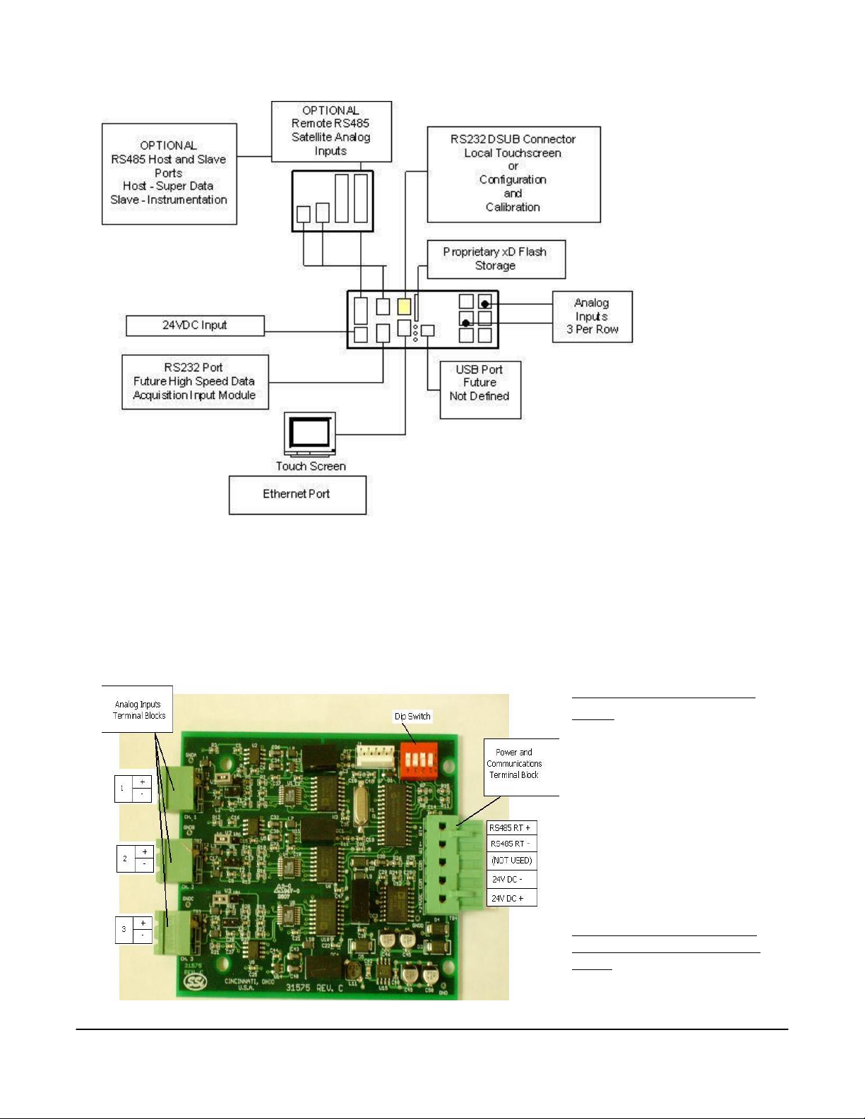
Analog Inputs
The Super Systems, Inc. Part Number 31575 Analog Board contains a group of three channels isolated
from the main DC power source. Each input is fully isolated. The board can be connected to
thermocouples, voltage sources from 20mV full scale to 1.28 Volts full scale, voltage sources from 0 V full
scale to 10 V DC full scale, or 4 – 20 mA current loops.
Adding a Jumper to an
Input
When measuring a 4-20mA
current signal or a voltage
signal, such as a
thermocouple, a jumper must
be placed on the
corresponding two or threeposition header. For example,
Input 1 would need to have a
jumper placed between the
pins labeled “I1” before
connecting a 4-20mA signal.
Failure to add the jumper will
result in damage to the circuit
board. The jumper may
already be present at each of
the three headers, but unless
Super Systems Inc. Page 5 Video Recorder Manual Version 2 Rev. B
Page 7
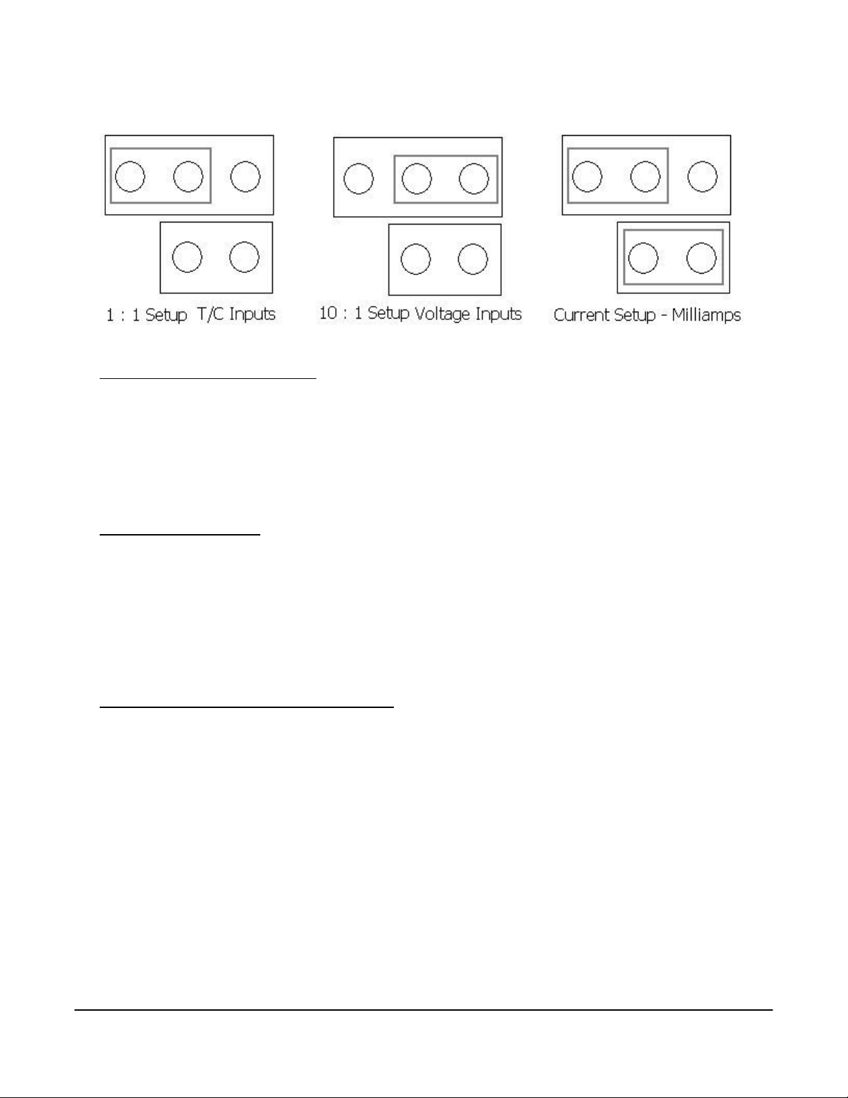
it is attached across both pins (not just one) it will not be connected.
Thermocouple connections
Thermocouple wires can be connected directly to the terminal blocks. The thermocouple junctions should
not be grounded. If they do touch a ground reference, all thermocouples on a board must have a common
ground reference. If multiple thermocouples are connected to different ground reference points, the
accuracy of all thermocouples on the board cannot be guaranteed to be accurate. When setting up a
voltage input signal, such as a thermocouple input or any voltage input signal up to 1.28 volts, the jumper
must be placed on the pins in the 1:1 setup (left diagram).
Voltage connections
Voltages from 0 mV to 10 Volts DC can be directly connected to the terminal blocks. When measuring
ground-referenced voltages, all references must share a common ground reference. If the voltage
sources are connected to different ground reference points, the accuracy of all the voltage sources
connected to the board need to be checked for accuracy. Since higher voltages can damage the input
board, any voltage input signals, such as a vacuum gauge, must have the jumpers placed on the pins in
the 10:1 setup (middle diagram). This will insure that any signal going into the board will be scaled down
so it will not damage the input board.
4 – 20 mA. Current Loop connections
Before connecting the current loop, insert the shorting jumper on the board for each channel used to
measure current loops. This jumper inserts the 62-ohm shunt resistor across the input of the A/D. If
multiple current loops are connected to one board, all must share the same power supply and ground
reference points or the accuracy of all the current loops need to be checked for accuracy. When setting
up a current input signal, such as a 4 – 20 mA signal, the jumper must be placed on the pins in the
current setup (right diagram). Notice that there is also a jumper set up in the 1:1 setup only when
inputting a current signal. This is because current signals also have a corresponding voltage signal.
Warning: Connecting a mA input without the Input Jumper will damage the
input.
1. To add a jumper to an input:
2. Power down the unit.
3. Remove the thermocouple connector and the Ethernet cable from the video recorder.
4. Remove the top plate of the video recorder by unscrewing the six (6) screws around the top of the
video recorder.
Super Systems Inc. Page 6 Video Recorder Manual Version 2 Rev. B
Page 8
5. Grasping both sides of the input board, carefully pull the input board out of the video recorder and set
the jumper for the appropriate set of pins, i.e. “V1” for input 1, “V2” for input 2, etc. A jumper will need
to be set – placed on both pins – to be considered “on”. Slide the input board back into the video
recorder slot.
6. Replace the top plate of the video recorder by screwing in the six (6) screws around the top of the
video recorder.
7. Re-connect the Ethernet cable and thermocouple connector.
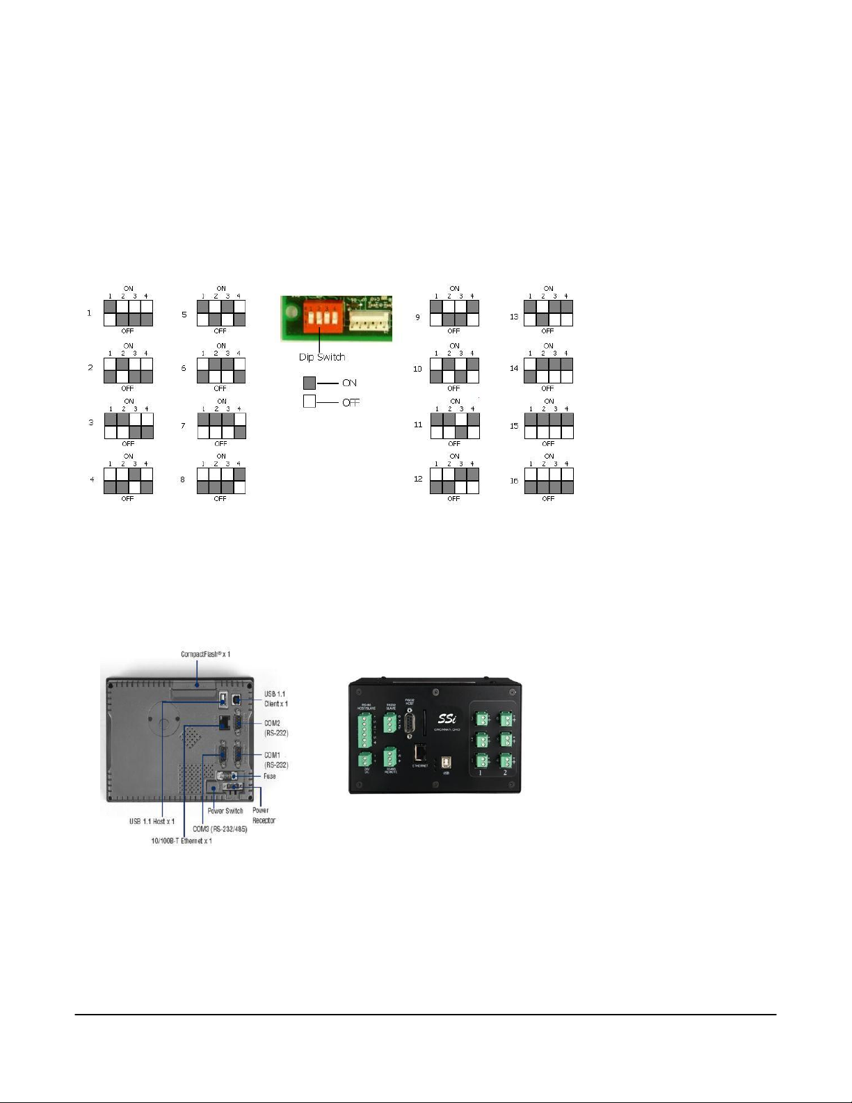
Setting the DIP switches to Assign Board Numbers
Each input board, whether
directly connected in the
Video Recorder or
connected through a
satellite box, must have a
unique address assigned
by the DIP switches on
each input board. A
unique address will
ensure that the Video
Recorder will correctly
read all of the boards set
up. If two or more boards
have the same address,
multiple errors could occur such as: VR reading data from one board one second, then reading data from
another board the next second, no data being read from the VR, etc.
unique address
binary numbering system – i.e. 1 = 1, 2 = 2, 3 = 4, and 4 = 8. There is an ON and an OFF position for each
switch. OFF = 0 and ON = 1. Each board number can be assigned by setting the appropriate switches to
ON. For example, to set a board number to 1, set the “1” switch to ON and the “2”, “3”, and “4” switches
to OFF ((1*1) + (2*0) + (4*0) + (8*0) = 1). To set the board number to 10, set the “1” and “3” switches to
OFF and the “2” and “4” switches to ON ((1*0) + (2*1) + (4*0) + (8*1) = 10).
. Each DIP switch has four switches on it labeled: 1, 2, 3, and 4. These numbers follow a
It is important that each board has a
The exception to the rule is
setting a board number to 16 – all
switches are off
.
Getting Started
The data logging device and the
touch screen have a unique IP
address. The communications
between the screen and the data
logger is performed through the
Ethernet ports. Both the screen
and data logger require separate and unique fixed IP addresses.
Super Systems Inc. Page 7 Video Recorder Manual Version 2 Rev. B
Page 9
Physical Installation
Mechanical Mounting
The 3 foot din rail (Allen-Bradley P/N 1492-N22) is mounted to the enclosure panel. Snap the video
recorder enclosure onto the DIN-rail.
Wiring
Connect power with 18 or 20 AWG wire and inline fuse holder as shown in either the
Network Connection
to the panel connector as shown in either the
Wiring Diagram – Direct Connection
diagram or the
Wiring Diagram – Direct Connection
Wiring Diagram – Network Connection
diagram.
diagram. Connect earth ground
Wiring Diagram –
diagram or the
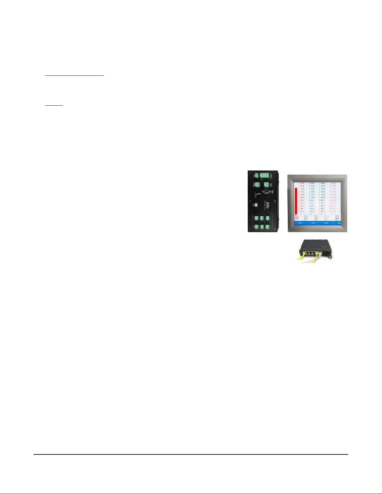
Connecting the Video Recorder to the Touch Screen
Every Video Recorder shipped includes a red Ethernet crossover cable
that will connect the Video Recorder to the screen. The screen and the
data logging device communicate either through the crossover cable
OR using an existing network.
If you are connecting the video recorder to your network, you will need
a straight-through Ethernet cable (the cable provided is a crossover
cable for direct connections to a PC) to be connected from the data
logging device to an Ethernet hub and the Touch Screen to an Ethernet
hub. The cable is plugged into the data logger Ethernet plug and then
other end should be plugged into a network hub. The IP address of the data logging
device will be provided with shipment.
If you are not putting the data logger on the network, you should use the red Ethernet
crossover cable that has been provided with the device. Ethernet crossover cables are most often
used when connecting two Ethernet computers without a hub. An Ethernet crossover cable has its send
and receive wires crossed. When using a hub or switch, this is automatically done for you.
With a crossover cable, you are forming a network between the computer that you are directly plugged
into and the touch screen. See the below section
diagram for a connection on a network, or
direct connection using the crossover cable.
Wiring Diagram – Direct Connection
Wiring Diagram – Network Connection
for a wiring diagram for a
for a wiring
Super Systems Inc. Page 8 Video Recorder Manual Version 2 Rev. B
Page 10
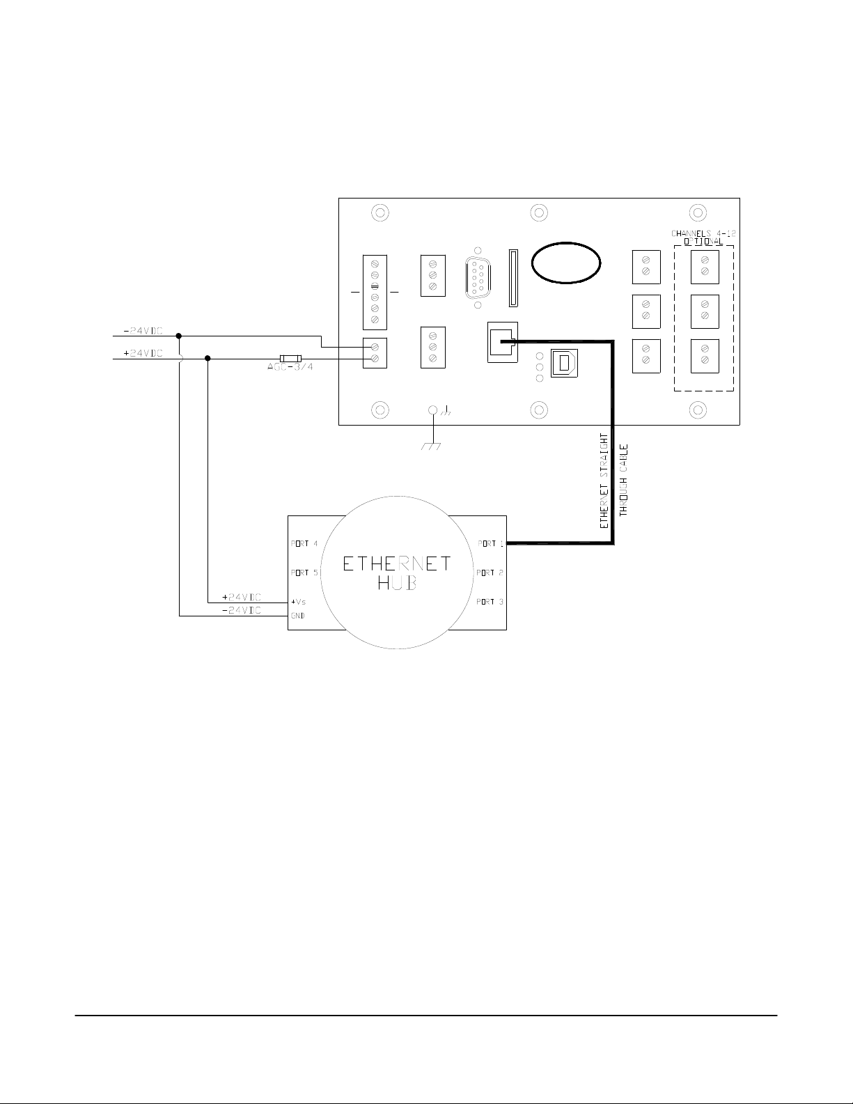
Wiring Diagram – Network Connection
-
DC
24V
HOST
REMOTE
USB
ETHERNET
RS485
+
+
S
+
S
-
21
1
+
-
4
+
-
+
2
+
5
-
RS485
HOST/SLAVE
SLAVE
S
+
-
TxRx
G
SLAVE
RS232
HOST
RS232
SSi
CINCINNATI, OHIO
+
3
+
6
-
Below is a wiring diagram for a network connection:
Super Systems Inc. Page 9 Video Recorder Manual Version 2 Rev. B
Page 11
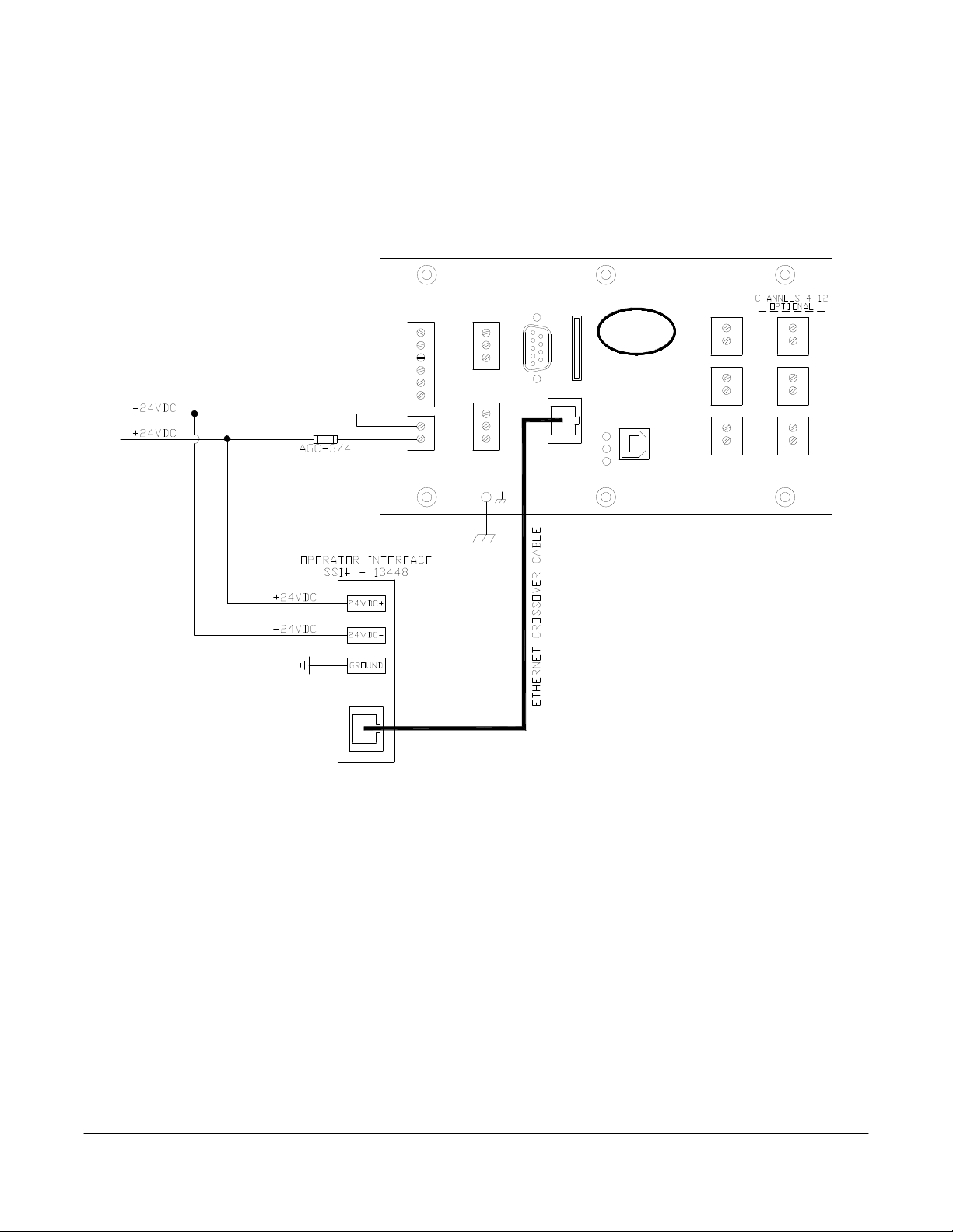
Wiring Diagram – Direct Connection
-
DC
24V
HOST
REMOTE
USB
ETHERNET
RS485
+
+
S
+
S
-
21
1
+
-
4
+
-
+
2
+
5
-
RS485
HOST/SLAVE
SLAVE
S
+
-
TxRx
G
SLAVE
RS232
HOST
RS232
SSi
CINCINNATI, OHIO
+
3
+
6
-
Below is a wiring diagram for a direct connection:
Super Systems Inc. Page 10 Video Recorder Manual Version 2 Rev. B
Page 12

Each screen and Video Logging device is configured and setup with a fixed IP address. The screen is
configured to communicate with a specific device. This is done through the
Address
Menu Option.
Configuration
Target VR IP
Change the IP Address of the Touch Screen
It is important to obtain an available IP address and correct Net Mask and Default Gateway from an
administrator or IT associate before changing any of the IP settings. In order to change the IP address of
the touch screen, the program must be shut down. Click on Start Menu Settings Network and Dialup Connections. This will display the Network settings screen. Double-Click on the existing connection
to display the properties. To specify an IP address, select the “Specify an IP address” option and fill in the
sections for the IP Address, Subnet Mask, and Default Gateway using the on-screen keyboard, which can
be started by clicking on the Pen/Paper icon in the lower right corner and then clicking on “Keyboard”
from the menu option. Move the keyboard to a position where you will still be able to see the IP address
section and the keyboard at the same time. Highlight the first section of the IP address and enter the IP
address.
two or one-digit section of the address, begin the section with zeroes, i.e., 001 instead of 1. Repeat for the
Subnet Mask and Default Gateway.
To have the IP address assigned by the network, select the “Obtain an IP address via DHCP” option. This
option will disable the text boxes for entering the IP address, since the IP address will be given by the
network. Click on the OK or X button on the top of the screen to close the screen.
address of the touch screen is changed, then the corresponding profile in the VR Manager will have to be
updated as well
Note – The cursor will move to the next section once three digits have been entered
Note – If the IP
.
. To enter a
Super Systems Inc. Page 11 Video Recorder Manual Version 2 Rev. B
Page 13

Touch Screen Interface
The VR Series recorder can be equipped with a touch screen operator interface, which is used to view the
different variables that are being recorded. When the screen is powered up with the 24 VDC supply and
connected to the VR series analog input base module, the Main screen appears.
The three options available are Display,
Configuration, and Template. Clicking on
the Display option will load the chart.
On the Chart screen, there are several variables displayed.
1. Template – the chart view with the chosen process variable.
2. Date/Time – the current date and time in real time or historical mode.
3. Decimal Values – actual value of trend variable.
4. Greeen arrows – Move the displayed information either forward or backward in time.
5. Chart Menu – More choices for displayed features.
Super Systems Inc. Page 12 Video Recorder Manual Version 2 Rev. B
Page 14
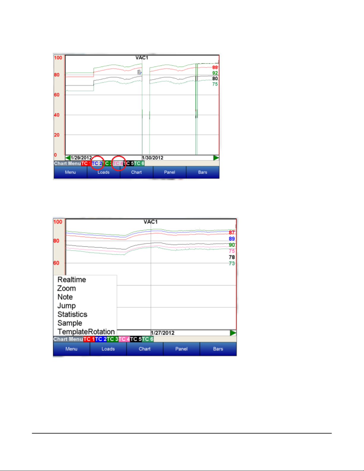
Selecting the Chart Menu provides more options for the display.
The inputs that appear on the chart
can be toggled between being
displayed or being left off simply by
tapping on the name of the input
along the bottom of the chart. The
box with the input number will turn
gray.
In this example, TC2 and TC4 are
left off of the chart display and are
in gray boxes.
Super Systems Inc. Page 13 Video Recorder Manual Version 2 Rev. B
Page 15
Realtime – Choosing this option sets the displayed values to the present date and time.
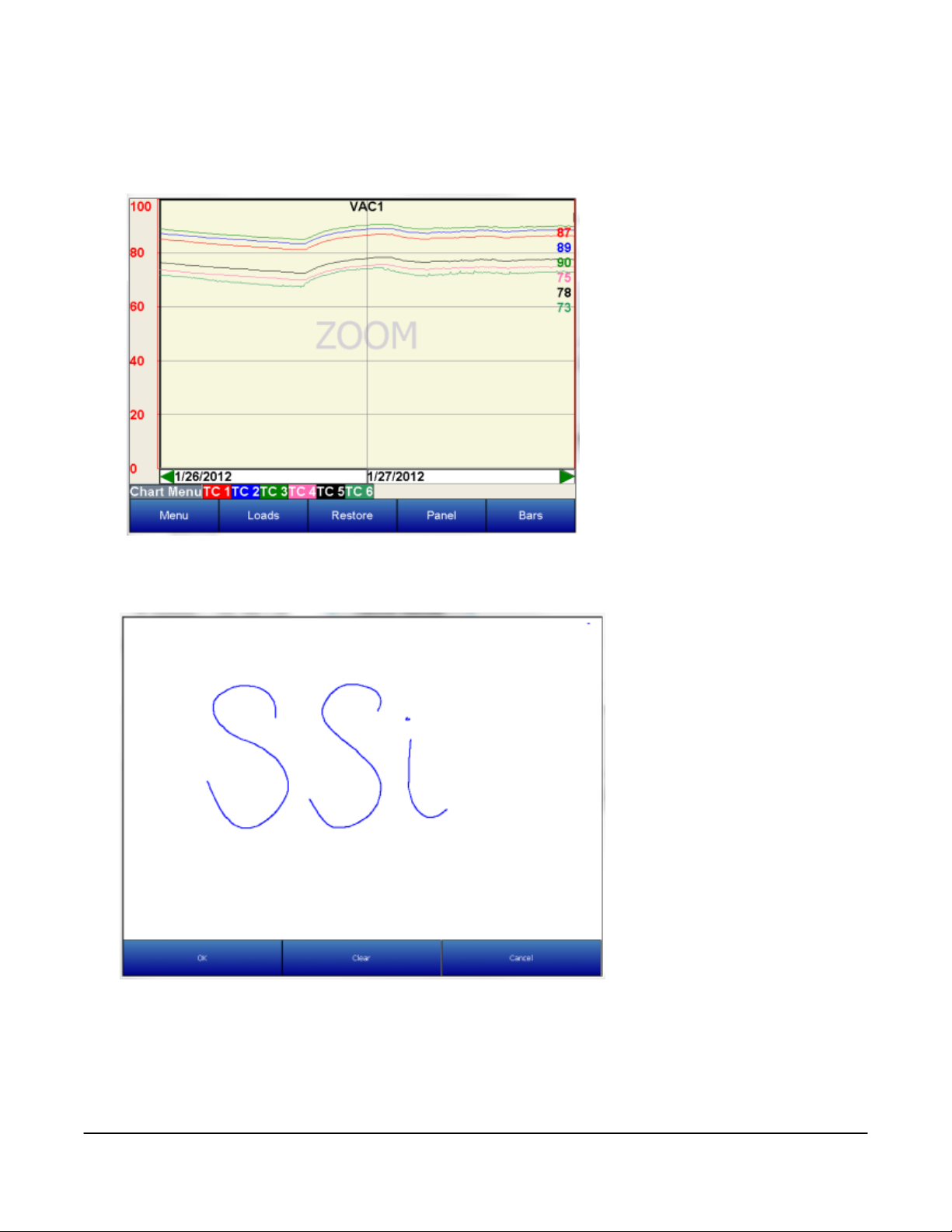
Zoom – This selection allows you to move your stylus or finger on the screen to a specific point creating a
box. The zoom box will also display decimal values for the low and high variables inside the box. It will
display the start and end time for
the zoom box itself. The zoom
feature can be used as often as
desired allowing the user to drill
down on the variable to show a
specific value displayed on the
screen.
Note – the Note feature
available on VR series
recorders allows the operator
to add notes in the chart
display. Notes can be added
using either a stylus or the
keyboard displayed on the
screen. Choose the Add Note
option from the Chart Menu
then select keyboard or stylus
to add a note.
Note on
keyboard functionality –
pressing the “caps” button or
the “shift” button will display
more keys for data entry. Also,
the “del” key works more like
the “Backspace” key on a
regular keyboard – i.e. it will
delete the character to the left
of the cursor
If a note requires editing select clear to retype or scribe the note or cancel to go back to the chart display.
.
Super Systems Inc. Page 14 Video Recorder Manual Version 2 Rev. B
Page 16
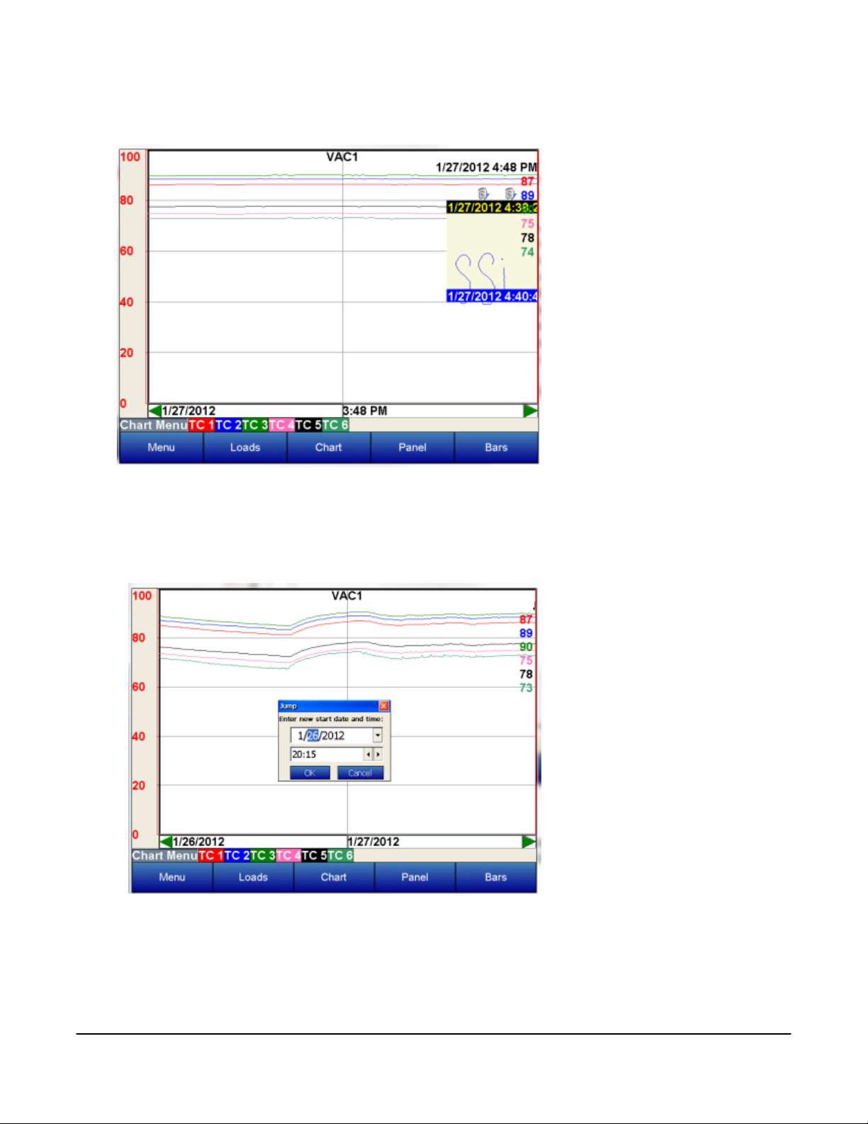
The note is displayed on the chart menu with a small icon. If the icon is touched it will expand to show the
information either scribed or typed onto the recorder.
Jump – This option allows the user to input the date and time to be displayed. The chart will jump to this
time.
Super Systems Inc. Page 15 Video Recorder Manual Version 2 Rev. B
Page 17

Statistics – The statistics option is also available on the chart menu. Choosing this option allows the
operator to view statistics on any
variable displayed on the operator
interface. The statistics are based
on the screen image displayed
whether looking at seven days of
data or zoomed in on a few
minutes.
The statistics parameters include
the trend name, the number of data
points available for calculating
statistics, the Minimum value, the
Maximum value, the Average value,
and the standard deviation.
Sample – Pre selected time frame formats change the displayed values on the screen to this duration.
Note: When the sample rate is
“15 minutes @ 1 sec”, the
averagers will not be displayed
on the trend chart (Touch
screen Versions 3.00 and
above).
Super Systems Inc. Page 16 Video Recorder Manual Version 2 Rev. B
Page 18
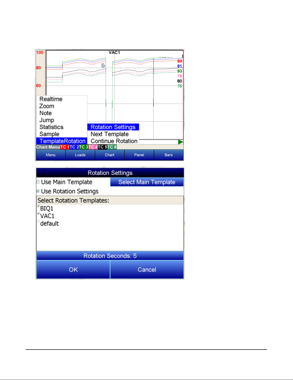
Template Roatation – This option enables the display to cycle through the different templates that have
been saved.
Selecting Rotation Settings
brings up a list of available
options for the display settings.
Checking the Use Main
Template box will keep the
display on one template. Select
Main Template allows the user
to decide which template to
display permanently if Use Main
Template is chosen. Checking
the Use Rotation Settings box
will enable the templates to
cycle. The templates to be
displayed can be customized by
checking or unchecking the box
next to each name under Select
Rotation Templates. The
amount of time each template is
displayed can be adjusted using
the Rotation Settings button.
Super Systems Inc. Page 17 Video Recorder Manual Version 2 Rev. B
Page 19
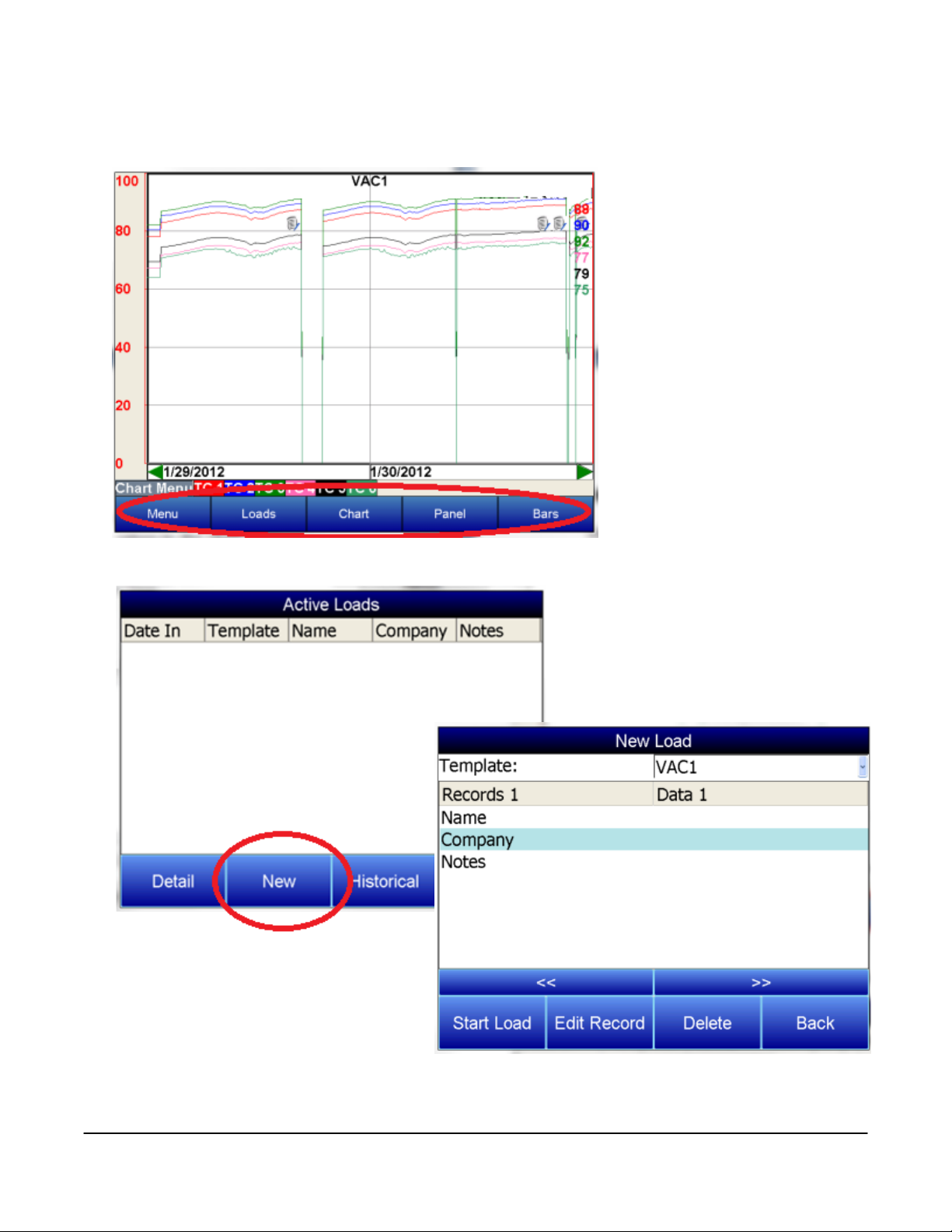
Along the bottom of the Display screen, there are other options for the way the template information is
presented.
The Loads button helps keep track of Active and Historical load data.
Pressing New will bring up the screen
for a New Load.
To input information about the new load, highlight any field, Name, Company, or Notes, and press Edit
Record. A keypad will display. Press enter on the keypad to save information, delete to backspace a
letter, and esc to leave the keypad without saving changes. Choose the corresponding template from the
Super Systems Inc. Page 18 Video Recorder Manual Version 2 Rev. B
Page 20
drop down menu along the top of the screen. When the load begins, press the Start Load button. When
the load finishes, choose End Load on the same screen.
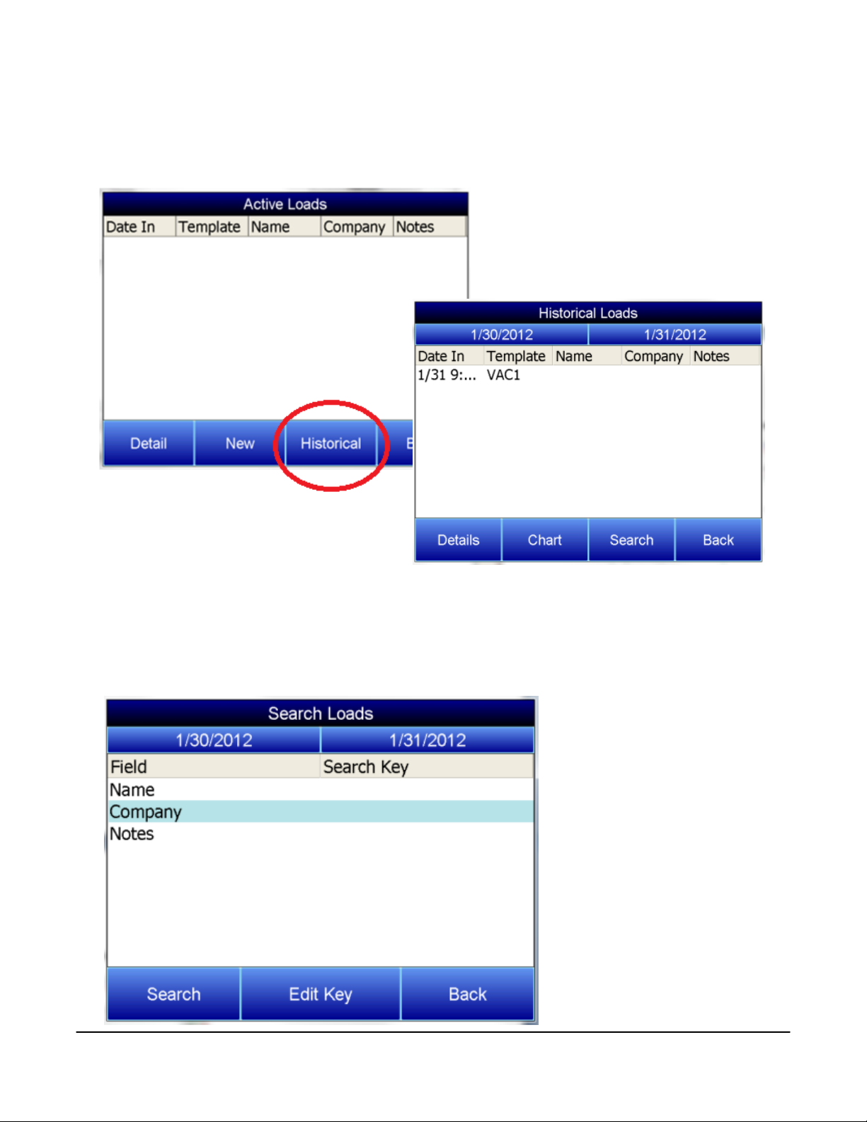
By pressing the Historical button on the loads screen, the historical load data will be displayed.
The Details button will display the information that has been stored about each load. The Search key
allows all historical load data to be searched through according to either the Name, Company, or within
the Notes. Only notes that have been entered with the keypad can be searched. Notes written the stylus
will not be included in searches.
To search historical loads, press the Search key.
Highlight the appropriate field
and press Edit Key. A keypad will
display. Press enter on the
keypad to save information,
delete to backspace a letter, and
esc to leave the keypad without
saving changes. Once the search
key(s) have been entered, press
the Search button, and a list of
matching results will be
displayed.
Super Systems Inc. Page 19 Video Recorder Manual Version 2 Rev. B
Page 21
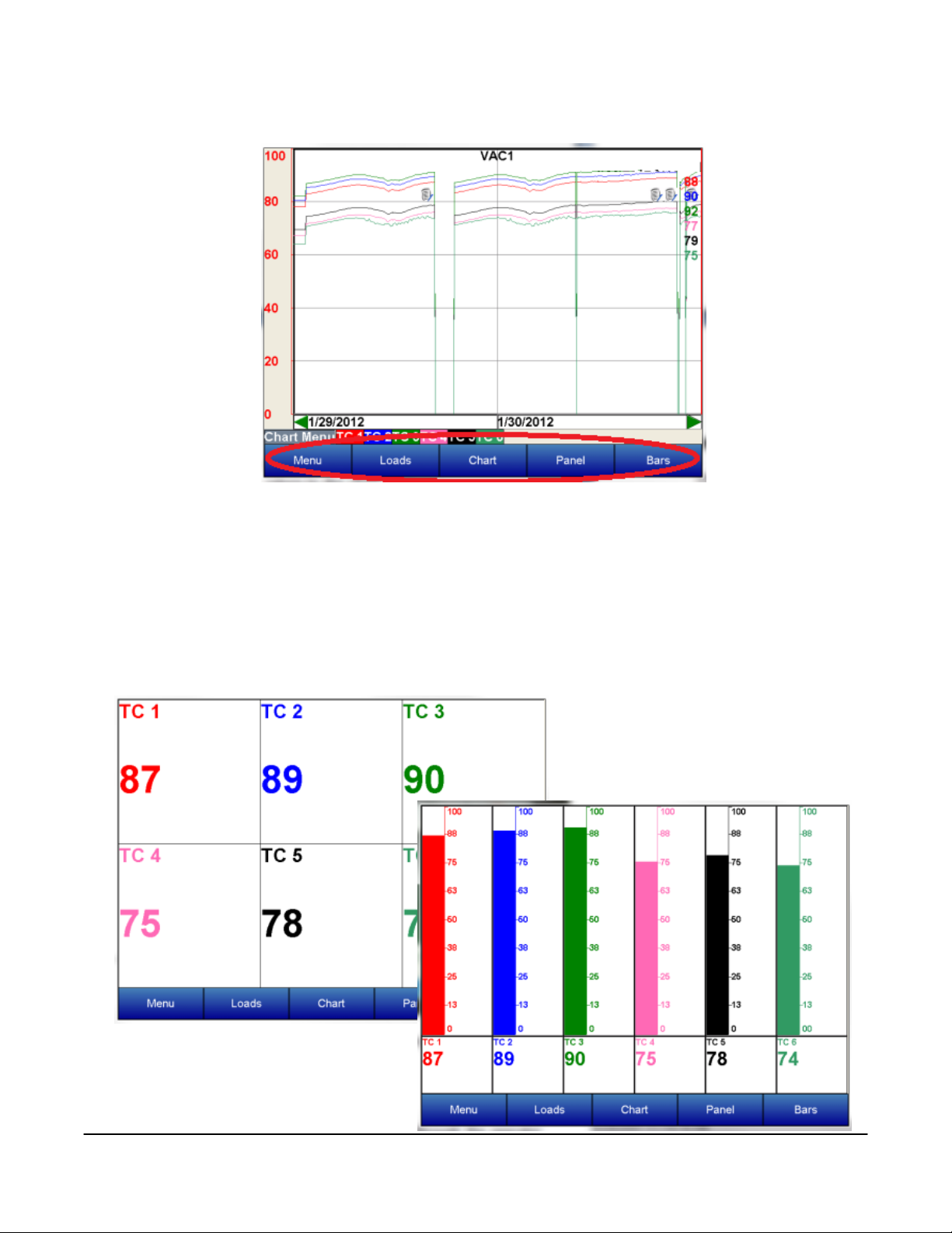
Returning to the main display screen, the data can also be displayed in a panel or bar format.
To select the panel view, view touch the Panel button on the bottom of the screen. In this mode,e decimal
values chosen for this template are displayed. Only realtime data can be displayed in the panel view.
Starting with version 3.12 of the screen software, it will be possible to send a setpoint down to a slave
instrument. The slave instrument’s setpoint must be included as a trend line. From the panel view
screen, touch the slave instrument’s setpoint panel and a menu will pop up that will allow the user to
send the setpoint down to the instrument. Select this option and enter the new setpoint.
A third choice for viewing variables on the VR operator interface is the Bars view. To select this view touch
the Bars button on the bottom of the screen. In this mode, the decimal values chosen for this template
are displayed as well as a vertical bar
chart for each variable with the
appropriate scaling for each. Only
realtime data can be displayed in the
Bars view.
Super Systems Inc. Page 20 Video Recorder Manual Version 2 Rev. B
Page 22
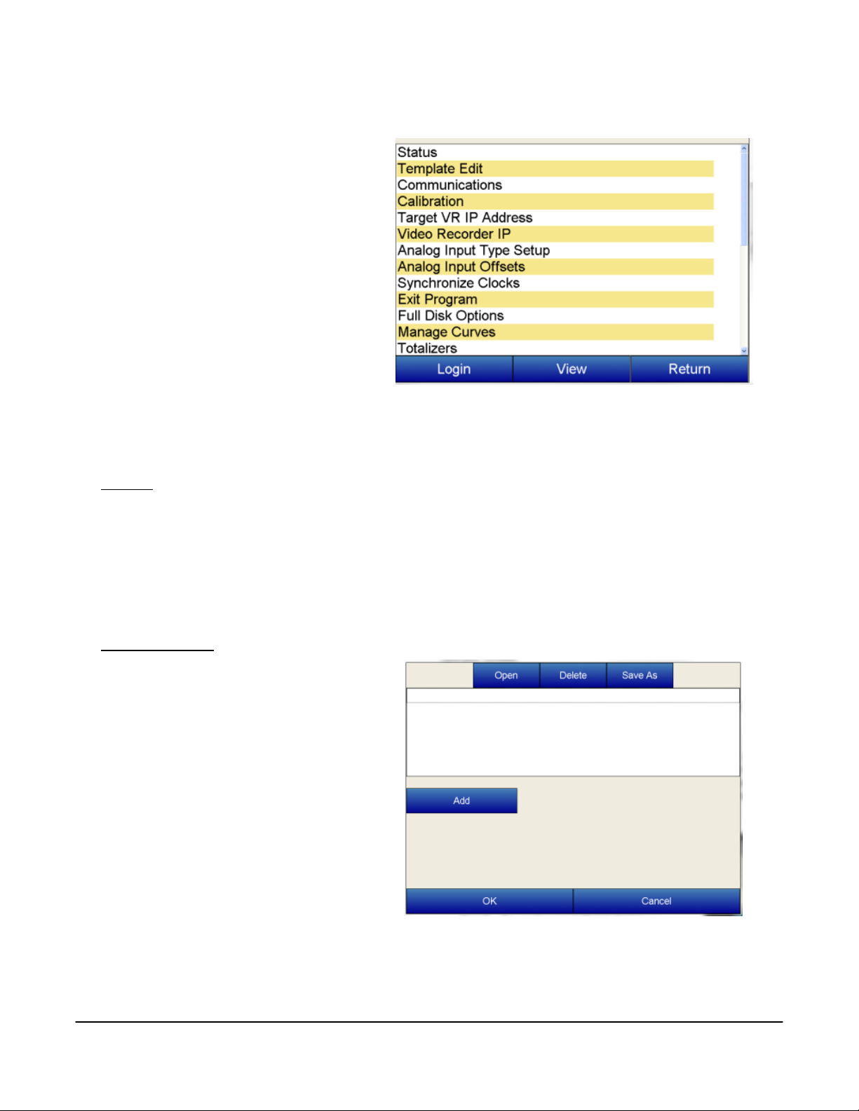
Configuration Menu
The VR recorder is configured through the
operator screen. The user must first select
the configuration button from the main
menu. Then choose the login button located
on the lower left of the next screen.
Login – Allows the operator to enter
a password to enter the
configuration of variables. The
password for logging in is “2”.
View – Allows the operator to view a
configuration parameter that has
been highlighted.
Return – pressing this button returns the operator interface to the previous viewing screen.
Press Login, type the password and press enter for configuration.
Status
Status – Includes the VR firmware revision, touch screen software revision, communication status,
remaining disk space, and estimated storage space remaining, which is displayed in number of days.
The communication status shows the status of communications from the VR base unit to the operator
touch screen. This will show either OK or BAD if communications have failed between the base and the
operator screen.
Template Edit
Template Edit allows the operator to edit an
existing template, or create a new template.
A template is the number of variables
displayed on one screen. For example this
could be a control, overtemp, or load
thermocouple on a batch furnace. Or it could
be one thermocouple from eight temper
furnaces. There is not a maximum for
template selections, but the number of
variables displayed on one screen must be a
consideration in this process.
To create a template the Add key is pressed
which allows the operator to configure the
following parameters.
Name – the name of the input, for example “Control T/C” which should be changed to the least
amount of understood characters “Ctl T/C”
Super Systems Inc. Page 21 Video Recorder Manual Version 2 Rev. B
Page 23
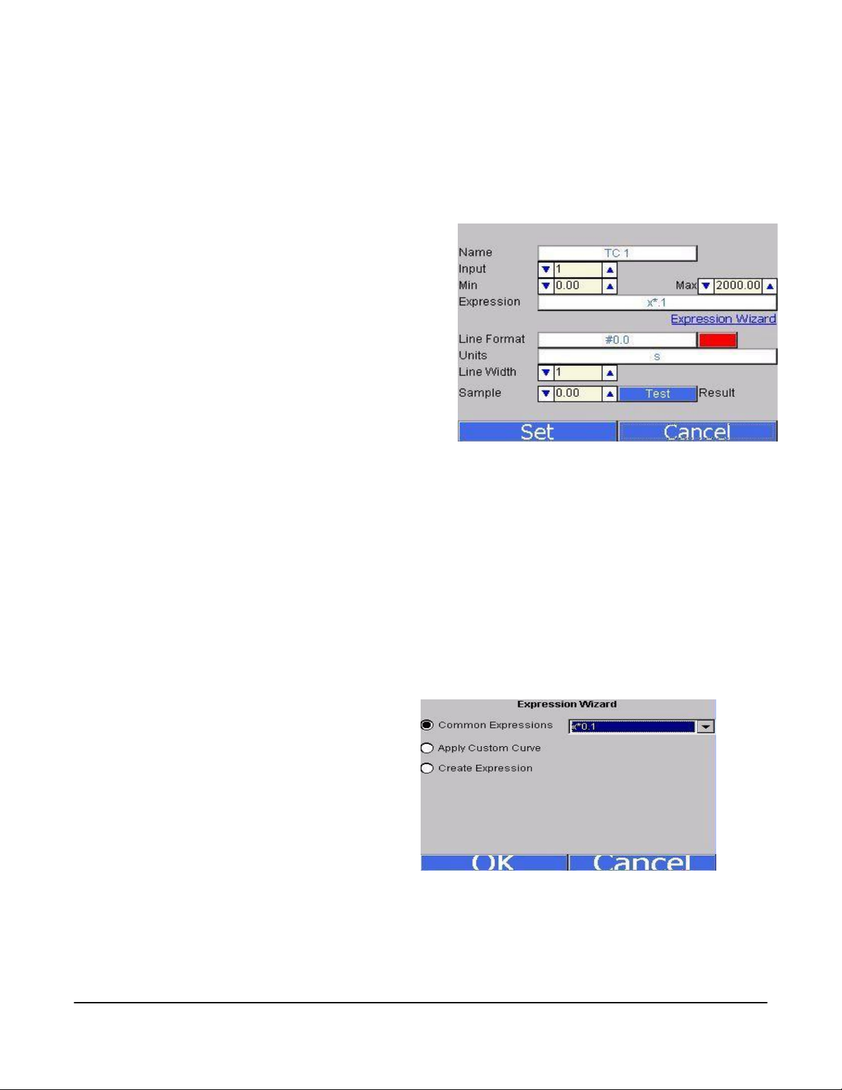
Input - the analog input that is being configured, for example on a VR5 this could be a channel from
one through five. The list of options is: TC 1 – TC 40, Averager Group 1 – Averager Group 3, Totalizer
1 – Totalizer 10, and Function Based Timer 1 – Function Based Timer 5. Plus, with version 3.11+ of
the screen software, Slave 1 Process Variable, Slave 1 Setpoint, Slave 1 % Output – Slave 10 Process
Variable, Slave 10 Setpoint, Slave 10 % Output are available for versions 2.01+ on the VR Brick.
Min – the minimum displayed scale value on a chart
Max – the maximum displayed scale value on a chart
Expression – every input requires an expression to
be calculated and displayed correctly. For example
an expression for thermocouple inputs would be x
*.1. Use the onscreen keyboard to enter an
expression.
Expression Wizard – This feature will allow the
operator to build an expression using either a
custom curve or a regular expression. See the
“Note About Expression Wizard” below for more
information about this feature.
Line Format – the value displayed on the chart display of the operator interface. A short custom
description can be added here. For example, to display one (1) decimal point, enter a value of “#0.0”.
For carbon values, enter a value of “#0.00” for 2 decimals. This would display a value like “0.81”.
Entering “#.00” would display a value of “.81”.
Units – The type of units used for the trend.
Line Width – a numeric value for the thickness of the trend line. A 1 is a thin line; A higher value =
thicker line width.
Sample – a number is entered here to test the expression.
Test – Press the test button to calculate the expression with the value entered in the sample
parameter. For example with and expression of x*.1 and a value of 250 entered in the sample
parameter will display a 25.0
Note About Expression Wizard
This option will allow the user to select either a
common expression, such as “x*.01”, a custom
curve created with the
Manage Curves
menu
option, or to create an expression.
Super Systems Inc. Page 22 Video Recorder Manual Version 2 Rev. B
Page 24
To use a common expression, select the “Common Expressions” menu option and select the desired
RS232 Modbus Host
Baud Rate
RS232 Modbus
Slave Baud Rate
RS485 Host
Mode
RS485 Host
Baud Rate
RS485 Slave
Mode
RS485 Slave Baud
Rate
Serial Address
expression from the drop-down list. Clicking on the
OK button will set the expression to the trend, but
clicking on the Cancel button will not set the
expression to the trend.
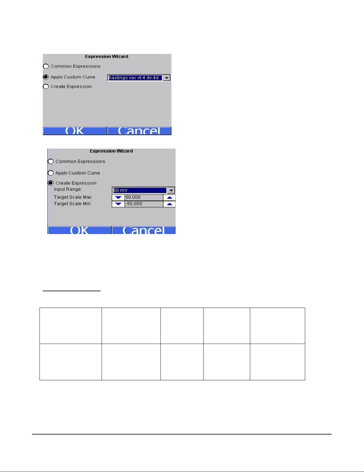
To use a custom curve, select the “Apply Custom
Curve” menu option and select the desired curve from
the drop-down list. Clicking on the OK button will set
the curve to the trend, but clicking on the Cancel
button will not set the curve to the trend. If a custom
curve is used, the “Expression” line will read “curve:
<Custom Curve>” where <Custom Curve> is the name
of the curve used.
To create an expression, select the “Create
Expression” menu option. Select the input range for
the trend from the drop-down list, and then select
the scale minimum and maximum. Clicking the OK
button will set the expression for the trend, but
clicking on the Cancel button will not set the
expression for the trend. The “Expression” line will
contain the new expression, if an expression was
created using the wizard.
Note – Expressions can
still be entered in the text box manually, as
described above
.
The “Open”, “Delete”, “Save As”, and “Save” buttons along the top of the screen will allow the user to
work with different templates, while the “Add”, “Edit”, and “Delete” buttons in the middle of the screen
allow the user to work with specific trend lines in a template.
Communications
Communications allows the operator to change the baud rate, or mode of these parameters:
The IP Address, IP Netmask, and the IP Gateway are also displayed on this screen, but they cannot be
configured from this screen. Starting with Version 3.12, this screen also contains the communications
status for any slave instruments that have been configured.
Super Systems Inc. Page 23 Video Recorder Manual Version 2 Rev. B
Page 25

Calibration
B C E J K N
NNM
R S T
0 – 2.56
0 – 1.28
160 mV
80 mV
40 mV
20 mV
4-20mA 124 ohms *Future Use
4-20mA 62 ohms
This menu option allows the operator to calibrate each input on the VR recorder. This will be covered in
detail in the
Input Calibration
section.
Target VR IP Address
Target VR IP address is the address of the operator screen or computer attached directly to the VR series
recorder. This address has to match the IP Address setup on the data logging device to display and store
data. Changing the IP address on this screen will point the screen to a different video recorder data
logger.
Video Recorder IP
This feature will display the IP address of the instrument that the VR is currently talking to and allow this
IP address to be changed. Changing this IP address will change the IP address of the instrument that the
VR is currently talking to. The VR will continue talking to the same instrument, however the IP address
for that instrument will have changed.
Analog Input Type Setup
For information about ensuring that the jumper is set up properly on a 4-20mA input, please
see the Analog Inputs section starting on page 6.
Analog Input Type – allows the operator to choose from the following parameters for each input of the VR
recorder:
Thermocouple Input Types
Voltage Input Types
Current Input Types
Super Systems Inc. Page 24 Video Recorder Manual Version 2 Rev. B
Page 26

Note – The 4-20 mA 124 ohms option is currently reserved for future use. Currently, when using a 4-20
mA input, be sure to select the 4-20 mA 62 ohms option
. For information about ensuring that the
jumper is set up properly on a 4-20mA input, please see the Analog Inputs section starting on
page 6.
Analog Input Offsets
Allows the operator to offset the input by a value entered for this parameter. For example if
thermocouple input is chosen as an input type, a value of 5 will increase the displayed value 5°. Scaling
of the input should be considered when entering an offset value for any input.
Synchronize Clocks
Choose this parameter to synchronize the clock in the operator interface with the clock in the analog
input base unit of the VR series recorder. This should only be performed when there has been a loss of
power or other data logging issues.
Exit the program
Clicking on this menu item will exit the program and display the Windows screen. The user will have to
confirm this action.
Full Disk Options
As the disk space on the flash card nears its capacity, the operator will have to decide how to handle the
data logging capabilities if there is not enough free space to continue data logging. There are two
options: “Overwrite Old Data”, or “Stop Datalogging”.
The first option, “Overwrite Old Data”, will begin to overwrite the oldest files when the free space goes
under 10 MB. The software will look for the oldest
compressed files and it will begin to delete those
files first. The software will delete around 5 MB and
then resume normal data logging. Once the disk
space gets below 10 MB again, these steps will be
repeated.
The second option, “Stop Datalogging”, will stop all
data logging and inform the user that data logging
has stopped. When this option is selected, the
software will not log data until the disk space has
been cleaned up.
Super Systems Inc. Page 25 Video Recorder Manual Version 2 Rev. B
Page 27

Manage Curves
decimal location: 0, 1, 2, 3, or 4. The “Value
Units” text box will allow the operator to
define the value units for the curve using the
onscreen keyboard. The Add Plot button will
allow the user to add a plot point to the
custom curve.
When the
down list will load with all of the custom curves that
have been set up, if any.
Clicking on the New button will allow the operator to add
a custom curve.
The operator will have to name the curve before being
able to edit a curve. The “Interpolation” drop-down list
contains two options: Polynomial or Linear. The “Input
Dec.” drop-down list has five options for the input
Manage Curves
screen loads up, the drop-
Use the up and down arrows to enter the desired input
and value. Clicking on the value will display the numeric
keypad, which will allow the user to enter the value that
way as well. Click on the OK button to set the values, or
click on the Cancel button to cancel the process.
The Edit Plot button will allow the operator to edit a
selected plot point, while the Delete Plot button will allow
the operator to delete a selected plot point. The operator will have to confirm the delete.
The Delete button will delete a selected curve. The operator will have to confirm the delete.
The Save As button will allow the operator to save the curve as another curve, while the Save button will
save the changes made to the current curve.
The Done button at the top of the screen will close the
Manage Curves
screen.
Super Systems Inc. Page 26 Video Recorder Manual Version 2 Rev. B
Page 28

Totalizers
This menu option will allow the user to add or
modify up to ten totalizers. If the totalizer selected
is already set up, then the user will be able to see
the type, the active inputs, and the date of the last
reset, which is where the totalizer is set back to
zero. If the totalizer is not already set up, the user
will only see the type and active inputs, which will be
blank. To select the type, click on the “Type” line
and then click the Edit button. The type can be one
of the following: Off, Seconds, Minutes, or Hours.
Select the desired type and click on the OK button to
set the type, or the Cancel button to cancel the
action.
To select the active inputs, click on the “Active
Inputs” line and then click on the Edit button.
This will display the screen where the user can
select the active inputs for the totalizer. To
select an input, the user can click on the desired
input, which will place a check mark next to the
input. The available inputs are Input 1 – Input 32.
After selecting the input(s), click on the OK
button to set the active inputs, or click on the
Cancel button to cancel the action.
screen may take a few seconds to update the
active inputs and display them
set to something other than Off, then the date of
the last reset will be displayed. If the “Type” is
changed from a value to Off, then the date of the
last reset will become invisible.
totalizer will be reset every time a value is given for the type
force a reset for the totalizer. The user will have to confirm the reset first. To reset a totalizer, click on
the “RESET” line and then click on the Edit button. A message box will pop up confirming the reset. Click
on the Yes button to confirm and reset the totalizer, or click on the No or Cancel button to cancel the
action.
. The “RESET” line will allow the user to
Note: The
. If the “Type” is
Note: The
Averagers
Averagers allow the user to get an average value from
one or more inputs and display that average on the
graph.
Select the averager group to work with from the dropdown list at the top of the screen. The options are:
Averager Group 1 – Averager Group 3. The first line,
“Enabled”, lets the user know if the selected averager
is enabled or not. Clicking on this line and then clicking
on the Edit button will allow the user to enable/disable
all three averager groups at once, instead of doing it
Super Systems Inc. Page 27 Video Recorder Manual Version 2 Rev. B
Page 29

one at a time.
Click on the averager group to enable/disable that group.
Click on the OK button to set the changes, or click on the
Cancel button to cancel the action. Clicking on the “Active
Inputs” line then clicking on the Edit button will allow the
user to select the active inputs for the averager. The
process is identical to selecting the active inputs for a
totalizer. Once the active inputs have been set, the
“Min|Avg|Max” line will populate with the appropriate data.
Function Based Timers
The function based timers will allow the user to monitor whether a specific input goes above a certain
setpoint and for how long the input is over the setpoint. Select the timer to work with from the drop-down
list. The options are: Timer 1 – Timer 5.
The function will determine what input to base the
timer off of. To select the function, click on the
“Function” line and then click on the Edit button.
This will bring up a list of functions to use. The
choices are: DISABLED (No timer function), or
Input 1 > Setpoint – Input 40 > Setpoint. Select the
desired option and click on the OK button to set
the function, or click on the Cancel button to
cancel the action.
function will reset the timer to zero
setpoint, click on the “Setpoint” line and then click
on the Edit button. This will bring up the numeric
keypad so the user can enter the desired setpoint.
Note: Setting a different setpoint will reset the timer to zero
entered, the timer will begin to count if the function’s condition exists. The value of the function is listed
on the “Value” line, which shows the timer in terms of days, hours, and minutes. The “Last Reset” line
will display the most recent date the timer was reset to zero. The “RESET” line will allow the user to
force a reset for the timer. The user will have to confirm the reset first. To reset a timer, click on the
“RESET” line and then click on the Edit button. A message box will pop up confirming the reset. Click on
the Yes button to confirm and reset the timer, or click on the No or Cancel button to cancel the action.
. Once a function and setpoint have been
Note: Function based timers can be added as an input on a template, but they will not be displayed on the
graph
.
Note: Selecting a different
. To set the
Alarm Text
This option will allow the alarm text displayed to be customized. Select the appropriate alarm number,
and press the Edit button. A keypad will display. Press enter on the keypad to save information, delete to
backspace a letter, and esc to leave the keypad without saving changes.
Super Systems Inc. Page 28 Video Recorder Manual Version 2 Rev. B
Page 30

Alarm Setup
This menu option allows the user to set up the
alarms for the screen. The user can set up to
twelve alarms per screen. Select the alarm to
edit from the drop down list at the top of the
screen. Once selected, the alarm’s settings will
be displayed.
The “Type” field will define what type of alarm
this alarm will be set up as.
The options are:
Off (No alarm)
Process (High)
Process (Low)
Band (In)
Band (Out)
Deviation (High)
Deviation (Low)
The “Setpoint” field will allow the user to set the setpoint for the alarm. This will bring up the numeric
keypad where the user can enter the setpoint.
The “Hysteresis” field will allow the user to set the hysteresis for the alarm. This will bring up the
numeric keypad where the user can enter the setpoint.
The “Input Source” field will allow the user to select the input or inputs to focus the alarm on. The
process is identical to selecting the active inputs for a totalizer.
The “Delay (sec)” field will allow the user to set the delay time, in seconds, for the alarm. This will bring
up the numeric keypad where the user can enter the setpoint.
The “Base” field will allow the user to set the base for the alarm. This will bring up the numeric keypad
where the user can enter the setpoint.
The two “State” fields are non-editable, and will display the state of the alarm.
The “Alarm Text” field will allow the user to give a text description that will be displayed on the screen
when the alarm is activated. The text of the alarm will also be referenced on the alarms report in the VR
Manager.
Purge Data
This menu option will allow the user to delete data in one of four ways. This menu option will be useful if
any of the following conditions apply:
There is a “Low disk space” alarm on the screen
Communication with the video recorder data logger has been down for a few hours and the user
needs to get that data from the data logger
The user believes that data is missing or is incorrect for the past week and would like to
synchronize just those hours and/or days
Super Systems Inc. Page 29 Video Recorder Manual Version 2 Rev. B
Page 31

The user wants to delete all data and completely resynchronize with the video recorder data
logger
Before, this would have been accomplished by shutting down the screen program and manually deleting
the files from the storage card. With this menu
option, the user can perform these operations
without shutting the screen program down. There is
a drop down list on the
allow the user to select what data is to be deleted.
The first option, “Recent Data”, will allow the user to delete the most recent data from the screen. Each
option will have a brief description listed on the screen that the user can scroll through and read. These
descriptions will also be listed in this manual.
Description – This option is useful if you have had an interruption in communications between the VR
screen and the VR brick (data logger). After purging recent data and restarting the screen, the screen
will download the data from the brick during the synchronization procedure. Assuming continuous
operation, data from the past 7 days is available for download from the VR brick.
Purge Data
screen that will
It may take up to 1 hour for the screen to download and compress the week of data.
The user will have the option to delete between 0 and 7 days, and 0 and 24 hours from the VR screen.
Clicking on the Purge button will delete the files. Clicking on the Cancel button will cancel the purge and
close out the screen. The user will have to confirm the purge.
Clicking on the Yes button will begin the file deletion. Clicking on the No button will cancel the delete
process. Since this process involves deleting data logged data, the user will have a second chance to
confirm the deletion.
Clicking on the Yes button will begin the file deletion. Clicking
on the No button will cancel the delete.
Since the VR screen will need to be restarted in order to
resynchronize with the data logger, the user will have the
option to restart the screen from the
Purge Data
menu.
Super Systems Inc. Page 30 Video Recorder Manual Version 2 Rev. B
Page 32

The second option, “All Data”, will allow users
the ability to delete all of the logged data from
the VR screen. This option can be used if the
user wishes to completely resynchronize the
VR screen with the VR data logger.
Description – This option deletes all log data
stored on the screen. After rebooting the
screen is rebooted, recent data will be
downloaded from the VR brick (data logger)
and compressed. This will take up to 1 hour to
complete.
The user will have to confirm the deletion
twice in order for the files to be deleted.
Since the VR screen will need to be restarted in order to resynchronize with the data logger, the user will
have the option to restart the screen from the
Purge Data
menu.
The third option, “Old Data”, will allow the users
the ability to delete older data from the VR
screen. The option can be used if the user
wishes to free up space on the storage card.
Description – This option is useful for freeing up
space on the flash card. Be sure that the data
you are deleting has been backed up, or is no
longer needed.
The user can select the start date from the list
box on the screen. The program will delete any
datalog files that are older than the selected
date.
To ensure that the datalog files are backed up before purging the data, it is recommended that the user
run the download option from the VR Manager (Download Data button on the main screen, or
Communications
The user will have to confirm the deletion twice in order for the files to be deleted.
Since there is no need to resynchronize the data on the screen with the data on the VR data logger, the
user will not have to restart the screen.
Advanced Download & Maintenance
menu option).
Tools
Super Systems Inc. Page 31 Video Recorder Manual Version 2 Rev. B
Page 33

The fourth option, “Advanced”, will allow the
users the ability to delete datalog data from
specific time frames. This option can be used to
free up space on the flash card, or to cause a
resynchronization between the VR screen and
data logger.
Description – This option deletes data between
two specific dates. If these dates fall within the
past week, you may choose to restart the screen
to synchronize that data.
The user can select the starting date and time
from the “Between:” section and the ending time from the “and” section.
The user will have to confirm the deletion twice in order for the files to be deleted.
Since the VR screen may need to be restarted in order to resynchronize with the data logger, the user will
have the option to restart the screen from the
Purge Data
menu.
Slave Instrument Setup
This menu option is only available with versions 2.01+ on
the VR Brick and with version 3.11+ of the screen software.
The Slave Instrument Setup menu option will allow the
user to set up to ten slave instruments off of the Video
Recorder. To set the slave type, select the appropriate
slave instrument type and press the Edit button.
slave instrument must be wired to the RS485 Slave
terminals on the Video Recorder brick
.
Note: Any
The list of possible slave types is:
SSi AC20/7EK/20Q/20PQ
SSi 7SL
9200 LP 1
9200 LP 2
9200 LP 3
AE Flow_Meter
Eur 2404, E2704 LP 1
Eur 2500 LP 1
Eur 2500 LP 2, E2704 LP 2
E2704 LP 3
Super Systems Inc. Page 32 Video Recorder Manual Version 2 Rev. B
Page 34

UDC 3300
Yoko UT320, UT350
Yoko UP350
Yoko 550 LP 1, 750 LP 1
Yoko 550, 750 LP 2
The slave address can be an integer ranging from 1 to 250. A value of 0 will disable the slave instrument,
and the address will be displayed as disabled.
Notes Search
To search for a certain word or phrase in the notes, press the click to input search phase button. A
keypad will be displayed.
Note on keyboard functionality – pressing the “caps” button or the “shift”
button will display more keys for data entry. Also, the “del” key works more like the “Backspace” key on
a regular keyboard – i.e. it will delete the character to the left of the cursor
saving, or enter to save the search criteria. A list of notes with this phrase will then be displayed. Only
notes written with the keypad can be searched. Notes written with the stylus will not be included in the
search.
Super Systems Inc. Page 33 Video Recorder Manual Version 2 Rev. B
. Press esc to go back without
Page 35

Loads
The Loads option keeps track of Active and Historical load data.
Pressing New will bring up the
screen for a New Load.
To input information about the new load, highlight any field, Name, Company, or Notes, and press Edit
Record. A keypad will display. Press enter on the keypad to save information, delete to backspace a
letter, and esc to leave the keypad without saving changes. Choose the corresponding template from the
drop down menu along the top of the screen. When the load begins, press the Start Load button. When
the load finishes, choose End Load on the same screen.
By pressing the Historical button on the
loads screen, the historical load data will
be displayed.
Super Systems Inc. Page 34 Video Recorder Manual Version 2 Rev. B
Page 36

The Details button will display the information that has been stored about each load. The Search key
allows all historical load data to be searched
through according to either the Name, Company, or
within the Notes. Only notes that have been entered
with the keypad can be searched. Notes written the
stylus will not be included in searches.
To search historical loads, press the Search key.
Highlight the appropriate field and press Edit Key. A
keypad will display. Press enter on the keypad to
save information, delete to backspace a letter, and
esc to leave the keypad without saving changes.
Once the search key(s) have been entered, press the
Search button, and a list of matching results will be
displayed.
Date Time Settings
The Date Time Settings option lets the user change
the current date and time from this menu.
Furthermore, the Date and Time settings can be
changed to 24 hour instead of AM/PM. For changes to
take effect, the screen must be shut down and
rebooted (See the Exit Program configuration menu
option).
User Fields
The User Fields feature allows for the Name, Company, and Notes asscotiated with a load to be either
displayed or hidden. To toggle between, select the appropriate field name and press the Show/Don’t
Show button.
Super Systems Inc. Page 35 Video Recorder Manual Version 2 Rev. B
Page 37

Passcodes
Passcodes allows the login numbers for the supervisor or administrator passcodes to be customized.
The administrator is the only login with access to this menu. To change the passcode, press the
corresponding box. A numerical keypad will be displayed. Select the new number and press Enter.
Menu Configuration
Menu configuration allows the Configuration Menu to be customized in terms of what is displayed
depedending on the login level. The Administrator is the only login with access to this menu. To adjust
whether or not the Menu Item is displayed, highlight the appropriate item and press either the Toggle
Operator or Toggle Supervisor button. If the status reads True, the item will be accessable in the
Super Systems Inc. Page 36 Video Recorder Manual Version 2 Rev. B
Page 38

configuration menu. If the status reads False, it will not appear in the configuration menu list. Press
Save to save changes.
Input Calibration – Screen Version 1.47 and Below
Note: To check the screen version number, click on
the
Status
menu option from the
The screen’s revision number will be listed next to the
“Touchscreen Revision” line
information to setup the calibration of the inputs.
Calibration can be performed 1 channel at a time or
from 1 – 5 inputs per board. The user can select board
one through sixteen from the selector box on the
bottom left of the screen. Clicking on the yellow area
will display the onscreen keyboard, which will allow
the operator to enter in the number of the board to
calibrate. Once a board has been selected, press the
Enter Cal Mode button to start the calibration process.
If the module is not communicating, the software will display an error message.
The user will need a thermocouple calibrator capable of outputting a thermocouple signal to calibrate the
zero, span or cold junction value of the video recorder data logger. The user will need to connect the
calibrator to one of the inputs on the data logger for the channel that will be calibrated. It is
recommended to let everything (calibrator and datalogger) sit for approximately thirty minutes to allow
the temperature to achieve equilibrium. Set up the calibrator for the specific thermocouple type of the
thermocouples in the video recorder datalogger, i.e. type K, type J, etc. Then, source a specific
temperature, like 1000 F, or millivolt to the connected input. It is recommended that the actual
temperature used be similar to an appropriate process temperature. For example, if your equipment
normally operates at 1700 F, then perform the cold junction calibration using a 1700 F signal. It is
important to note that when performing a zero or span calibration,
wiring. Instead, use any kind of regular sensor wire, or even regular copper wire. To perform the
calibrations, the user will need a calibrator that is capable of outputting volts, millivolts, and
temperature.
do not use
Configuration
. This screen displays
regular thermocouple
menu.
Below is a listing of the suggested ranges for the various TC types.
TC Type mV Range Chart
TC Type Range in mV
B 20
C 40
E 80
J 80
K 80
N 80
NNM 80
Super Systems Inc. Page 37 Video Recorder Manual Version 2 Rev. B
Page 39

Zero Calibration
R 40
S 20
T 20
To perform a zero calibration, click on the “Zero”
option. The circle will be filled in for the selected
option. The drop down list under “Range” will
allow the user to select the millivolt range of the
inputs being calibrated. When a range is
selected, the recommended value will also be
populated. For a zero calibration, the
recommended value is 0. The list of ranges is:
20 mV
40 mV
80 mV
160 mV
1.28 Volt
2.56 Volt
The recommended value can be changed either by using the up and down arrows to adjust the value, or
by clicking on the value, which will display the numeric keypad. The user can enter the new value in that
way. The user can also individually select each input (one through five) to calibrate, where Check = yes
(calibrate) and No Check = no (do not calibrate). Once an input is checked, its current value will be
displayed.
For a zero calibration, a value of 0 mV will need to be sourced to the input or inputs.
Click on the Calibrate button to begin the calibration.
A progress bar will be displayed along the bottom of the screen giving the progress of the calibration.
Span Calibration
To perform a span calibration, click on the
“Span” option. The circle will be filled in for the
selected option. The drop down list under
“Range” will allow the user to select the
millivolt range of the inputs being calibrated.
When a range is selected, the recommended
value will also be populated. For a span
calibration, the recommended value is 90 % of
the full range. For example, if the range is 80
mV, then the span should be 75. The
recommended value can be changed either by
using the up and down arrows to adjust the
value, or by clicking on the value, which will
display the numeric keypad. The user can enter
the new value in that way.
Note: If the user is
Super Systems Inc. Page 38 Video Recorder Manual Version 2 Rev. B
Page 40

using a 10:1 jumper (see the
will need to multiply the source signal by 10 to get the correct span value
jumper is set on a 1.25V range, the suggested source signal will read 1000 mV. The supplied signal will
need to be 10000 mV to account for the 10:1 jumper. The user can also individually select each input (one
through five) to calibrate, where Check = yes (calibrate) and No Check = no (do not calibrate). Once an
input is checked, its current value will be displayed.
For a span calibration, a value of 90 % of the full range will need to be sourced to the input or inputs.
Click on the Calibrate button to begin the calibration.
A progress bar will be displayed along the bottom of the screen giving the progress of the calibration.
Adding a Jumper to an Input
section in the
Analog Inputs
. For example, if the 10:1
section), the user
Cold Junction Adjust
To perform a cold junction adjust, click on the
“CJ Adjust” option. The circle will be filled in for
the selected option. The cold junction offset can
be entered by using the up and down arrows to
modify the “Enter Cold Junction Offset” value.
The user could also click on the value, which will
display the numeric keypad, which will allow the
user to enter the new value in that way. The cold
junction adjust will adjust all of the inputs on one
board simultaneously.
Note – To subtract a
value from the current cold junction value, be
sure to set the offset value as a minus value by
clicking on the plus/minus key on the keypad (+/)
.
The overall Cold Junction value is modified by
adding or subtracting a value to the current
value.
Click on the Calibrate button to begin the calibration.
A progress bar will be displayed along the bottom of the screen giving the progress of the calibration.
Press the Exit Cal Mode to return to the previous
screen and select a different board. Pressing
the Done button from that screen will exit the
calibration menu item.
Input Calibration – Screen Version
1.49 and Above
The user will need a thermocouple calibrator
capable of outputting a thermocouple signal to
calibrate the zero, span or cold junction value of
the video recorder data logger. The user will
need to connect the calibrator to one of the
inputs on the data logger for the channel that
will be calibrated. It is recommended to let
everything (calibrator and datalogger) sit for approximately thirty minutes to allow the temperature to
achieve equilibrium. Set up the calibrator for the specific thermocouple type of the thermocouples in the
Super Systems Inc. Page 39 Video Recorder Manual Version 2 Rev. B
Page 41

video recorder datalogger, i.e. type K, type J, etc. Then, source a specific temperature, like 1000 F, or
millivolt to the connected input. It is recommended that the actual temperature used be similar to an
appropriate process temperature. For example, if your equipment normally operates at 1700 F, then
perform the cold junction calibration using a 1700 F signal. It is important to note that when performing
a zero or span calibration,
sensor wire, or even regular copper wire. To perform the calibrations, the user will need a calibrator that
is capable of outputting volts, millivolts, and temperature.
do not use
regular thermocouple wiring. Instead, use any kind of regular
Note: To check the screen version number, click on the
menu. The screen’s revision number will be listed next to the “Touchscreen Revision” line
Calibration
settings. When the settings have been loaded, the Calibration tab will be displayed.
If an existing input board is selected in the “Analog Input Card” section, then that input board’s firmware
revision number will be displayed next to the input board number and the inputs to be calibrated will be
enabled (see the figure on the left above). If a non-existing board is selected, there will be no firmware
revision number shown and the inputs to be calibrated will be disabled (see the figure on the right above).
menu is first selected, the screen software must first load up the screen’s configuration
The user will be able to select boards 1 through 8. Select
the inputs to calibrate by checking the checkbox next to each
input where: check = Yes (calibrate) and no check = No (do
not calibrate). Once the inputs to calibrate have been
chosen, press the Enter Cal Mode button to begin the
calibration process.
Status
menu option from the
Configuration
. When the
Once the calibration screen is displayed, the drop-down list
on the left of the screen will allow the user to select either
Zero Cal or Span Cal, depending on which calibration is
desired.
The “Input Values (mV)” section will display the selected
inputs and the associated values for those inputs. If an input has not been selected from the previous
screen, that input’s value will be dashes “---”. The “Calibration Range” drop-down list will allow the user
to select the appropriate range for the thermocouples. See the
range is not known for a specific thermocouple type.
Super Systems Inc. Page 40 Video Recorder Manual Version 2 Rev. B
TC Type mV Range Chart
on page 35 if the
Page 42

For a zero calibration, a value of 0 mV will need to be sourced to the input or inputs, and the “Enter
Source:” field should be set to 0.00. A recommended value will be displayed next to the “Recommended
Value:” field.
For a span calibration, a value of 90 % of the full range will need to be sourced to the input or inputs, and
the “Enter Source:” field should be set to 90% of the full mV range. A recommended value will be
displayed next to the “Recommended Value:” field.
Note: If the user is using a 10:1 jumper (see the
Adding a Jumper to an Input
section in the
Analog Inputs
section), the user will need to multiply the source signal
by 10 to get the correct span value
10:1 jumper is set on a 1.25V range, the suggested
source signal will read 1000 mV. The supplied signal
will need to be 10000 mV to account for the 10:1 jumper.
Press the Calibrate button to begin the calibration.
Press the Cancel button to cancel the calibration and
return to the previous screen.
The Cold Junction tab will allow the user to set the cold
junction offset for a specific input on a specific board.
The board being calibrated will be listed in the “Board #x, Input:” line, where x is the board selected from
the Calibration tab. The drop-down list will allow the user to select the input to set a cold junction offset
for. The “Current Input Value” line will display the selected input’s current value. The “Apply Offset:” box
will allow the user to select the cold junction offset to set.
Press the Apply Cold Junction Offset button to apply the selected offset.
. For example, if the
Super Systems Inc. Page 41 Video Recorder Manual Version 2 Rev. B
Page 43

The “Exit” link at the top right of the screen will exit the
Calibration
menu option.
Changing the Date/Time of the Touch Screen display
If the date or time needs to be changed on the Touch Screen display unit, use the following steps:
1. Exit the Video Recorder display by selecting the “Exit Program” menu option from the
“Configuration” menu.
a. Click on the View button along the bottom of the screen to select the menu option.
b. Click on the Yes button to confirm the program close.
2. Once the Video Recorder display has closed, double-click on the time in the taskbar in the lower
left corner. This will bring up the dialog to change the date or time.
OR
3. Go to Start Menu Settings Control Panel
a. Click on “Date/Time” once and select File Open or
b. Double-click the “Date/Time” icon to open the Date/Time dialog
4. If necessary, select the new date from the calendar by clicking on the date. Months can be
changed by using the left or right arrow buttons next to the month/year on the calendar.
5. If portions of the dialog are not visible due to the screen size, click and hold the title bar and move
the dialog by dragging the dialog.
6. If necessary, select the new time zone from the drop-down list.
7. Check the “Automatically adjust clock for daylight saving” checkbox if desired.
8. If necessary, adjust the time:
a. Highlight the hours, minutes, or seconds by clicking on the desired section. When
selected section will be highlighted in blue.
b. Use the up or down arrows to change the selected section
9. Click on the Apply button or the OK button at the top of the dialog to save the changes
10. If no changes were made, click on the X button in the top right of the dialog to close the dialog
11. Cycle the power to the Video Recorder Touch Screen to bring up the Video Recorder display.
Super Systems Inc. Page 42 Video Recorder Manual Version 2 Rev. B
Page 44

Remote Trend Web Page
Each touch screen will also contain a simple web page that will display the trend information for all of the
templates. However, before anyone can view this web page, the web server may need to be configured.
Open a web browser such as Internet Explorer or Mozilla Firefox, and enter the following into the address
bar: http://<
Touch Screen IP >
where < Touch
Screen IP > is the
IP address of the
touch screen
the video
recorder box).
This will display
the web page.
The templates are
listed in the dropdown list next to
“Trend
Template:”. Once
a template has
been selected,
the trends will be
displayed
underneath. The
current date and time of the touch screen will be displayed beneath the trends.
(not
If the above web page is not displayed, then the web server on the touch screen will need to be
configured. First, enter the following address into a web browser’s address bar:
http://< Touch Screen IP
>/remoteadmin where
< Touch Screen IP > is
the IP address of the
touch screen.
This will display the
remote administration
page for the touch
screen
Enter a password in the
“Password:” and
“Verification:” fields and
then click on the Apply
button. Clicking on the
Cancel button will clear
out the 2 fields.
This operation will only have to be performed once
web page. The user name will be “admin”. The web server will reset and then it will load the same web
page again.
. This will set up the administration password for the
Note –
Super Systems Inc. Page 43 Video Recorder Manual Version 2 Rev. B
Page 45

When the page reloads, you will be prompted for the username and password. If you are asked for a
domain name, leave the domain name blank. Remember – the user name is “admin”.
Once you are logged in, you will be asked to assign a device name. Use the serial number located on the
back of the touch screen – i.e. HMB0000000.
Super Systems Inc. Page 44 Video Recorder Manual Version 2 Rev. B
Page 46

Clicking on the Cancel button will reset the device name. Once the new device name has been entered,
click on the Apply button.
You will see the device name listed.
We now have to access the web administration page.
Type the following into the web browser’s address bar:
http://< Touch Screen IP >/webadmin where < Touch Screen IP > is the IP address of the touch
screen. This will display the Web Server Configuration page.
Super Systems Inc. Page 45 Video Recorder Manual Version 2 Rev. B
Page 47

Click on the Modify button located next to the “Default Web site” text.
Super Systems Inc. Page 46 Video Recorder Manual Version 2 Rev. B
Page 48

Immediately under the
“Default” Web Site
there will be a series of
links. Click on the link
titled “Configure the
virtual directories on
this web site”.
The virtual path that you
want to modify is the
base path of the web
server, which is just a
slash ( / ). The default
physical path for the
base path is
“\HardDisk\”. Click on
the Modify button for
the base path of the web
server.
In the text box which reads “\HardDisk\” under “Physical Directory or Redirection URL” in the “Virtual
path mapping” section, replace “\HardDisk\” with “\Storage Card\web\”.
typed as two words
Scroll down to the bottom of the page and click on the Update button.
.
Note: If the screen is a 12” screen, then the directory will be “\HardDisk\web”
Note – Storage Card must be
title,
.
You will see some
text at the top of the
screen letting you
know that your
changes have been
saved. You will now
need to restart the
web server. Click
on the Restart Web
Server button from
the list of menu
buttons along the
top left of the
screen (it will be the
last button). If all of
the necessary files
are already located
on the screen, you
should now be able to view the trend page. Enter the following into the address bar of a web browser:
http://< Touch Screen IP > where < Touch Screen IP > is the IP address of the touch screen.
may need to give the web server a few minutes to restart before viewing the trend page
Note – you
.
Super Systems Inc. Page 47 Video Recorder Manual Version 2 Rev. B
Page 49

Video Recorder Web Page
Each Video Recorder unit will
also contain a simple web
page that the user will be able
to view. The web page will
display the current values of
all of the inputs on the video
recorder unit, plus any
alarms. The web page will
display information for sixteen
boards, even if the Video
Recorder unit does not have
sixteen input boards installed.
Any line for an input board
that is not installed will
display asterisks (*). To
access the web page, enter
the IP address of the Video
Recorder unit itself into the
address bar of any Internet
browser, such as Internet
Explorer or Mozilla Firefox,
i.e. http://<VR Unit IP
Address> where <VR Unit IP
Address> is the IP address of
the unit. For example, if the IP address was “192.168.1.216”, then to access the Video Recorder unit’s
web page, the user will have to enter “http://192.168.1.216” into the web browser’s address bar.
An Internet connection is not needed to access the Video Recorder unit’s web page
.
Note:
Super Systems Inc. Page 48 Video Recorder Manual Version 2 Rev. B
Page 50

VR Manager Software
Installing the VR Manager Software
Note – The person installing the VR Manager Software must have administrative rights on the
computer(s) where the installation is taking place for the installation to be successful.
If there is no install file, make sure the following six files are located in the same folder:
VRManager.exe
AutoUpgrade.exe
AutoUpgrade.Lib.dll
SSiControls.dll
SSiLibrary.dll
ZedGraph.dll
If there is a setup file, follow these
instructions. Double-click on the
setup file, VRManagerSetup.msi to
start the auto-installation. If there is
no version of the VR Manager running
on the computer, the installation will
display a splash screen. Click on the
Next > button to begin the installation.
the installer.
Click on the Cancel button to cancel
the installation. The user will have to
confirm the cancellation.
Click on the Finish button to close out
Super Systems Inc. Page 49 Video Recorder Manual Version 2 Rev. B
Page 51

Since the VR Manager software uses the
Microsoft .NET 2.0 framework, the framework
must be installed on the computer in order for
the software to run. If you are unsure if the .NET
framework is installed on the computer, contact
Super Systems Inc at 800-666-4330. If the .NET
2.0 framework is not
installed, click on the
Cancel button to close out
the installer and install the
framework. The user will
have to confirm the
cancellation.
Note: The
.NET framework
installation file is named
“dotnetfx.exe”.
Clicking on the < Back button will
display the previous screen, and clicking on
the Next > button will display the next
screen. The next screen will prompt the
user for the download location.
The default location is “C:\SSI\”.
Note: The installer will automatically create a “Bin” folder to install the
files to. For example, if the default location, “C:\SSi\” is used, then the files will be installed to
“C:\SSi\Bin”.
button will display the available computer drives onto which the SDS Reporter can be downloaded, as well
as the total space, available space, required space, and the difference between the available and required
space for each drive.
process. The user will have to confirm the
cancellation.
Clicking on the Cancel button will cancel the
installation process. The user will have to confirm
the cancellation. Clicking on the < Back button
will display the previous page. Clicking on the
Install button will install the software to the
specified location.
Click on the Browse button to select an alternate location. Clicking on the Disk Usage
Clicking on the OK button will close out the
disk usage screen. Clicking on the < Back
button will display the previous screen.
Clicking the Next > button will continue with
the installation process. Clicking on the
Cancel button will cancel the installation
Super Systems Inc. Page 50 Video Recorder Manual Version 2 Rev. B
Page 52

Once the software has been installed, the VR Manager will
be ready to use.
Click on the Next > button to continue.
installer.
If there is a version of the VR Manager already
installed on the computer, the installer will
either re-install the software (Repair button) or
remove the software from the computer
(Remove button). Clicking on the Cancel button
will cancel the actions. The user will have to
confirm the cancellation.
Note: the installer
does not remove any subfolders in the main VR
Manager folder. These files will have to be
manually removed
.
The last screen is a description of the software used
to install the VR Manager software. Clicking on the
dev4pc.com button will display the dev4pc.com
homepage, the authors of the installer software.
Clicking on the Finish button will close out the
Super Systems Inc. Page 51 Video Recorder Manual Version 2 Rev. B
Page 53

The
Repair
option will allow the user to repair the installed files. This option is useful if the installation
was interrupted in some way and did not finish on its own. The
executable file from the computer.
VR Manager Minimum System Requirements
Remove
option will remove the main
Computer with a minimum of 600 MHz processor clock speed (Intel, AMD, etc).
Operating System – Microsoft Windows 98/2000/XP/Vista
Memory – 256 MB RAM or higher
Disk Space - Minimum of 1 GB storage space
CD-ROM drive or DVD-ROM drive
Keyboard and mouse
Monitor with 1024 x 768 resolution or higher and 256 colors
The VR Manager also requires the .NET Framework version 2.0 to be installed on the computer. The
install file for the .NET framework is located on the setup disk included with the Video Recorder shipment
VR Manager Overview
The VR Manager software provides all the necessary utilities to collect, review and print data that is being
logged on SSi Video Recorders. The software can be used to retrieve data over the network when the VR
Recorders are hooked up to the same network as the computer or data can be retrieved from the flash
card using the flash card reader, which is included with the shipment.
Super Systems Inc. Page 52 Video Recorder Manual Version 2 Rev. B
Page 54

VR Manager Screen
There are drop down lists
and buttons that activate the
functions on the screen.
The screen is used to
Select
Video
Recorders
to Manage
Review
Historical
Trend Data
In Graphical
and Data
Grid Format
Review
Notes
Written on
Screen
Print Trend
and Data
Grid
Export Data
to File
Select Chart Data Interval
Look at Specific Data Points
Download Data from Video Recorder
Review Statistics of Displayed Data
Pan Through Historical Data
Zoom In Display
Save Displayed Image
Turn On/Off Trend Points
Backup Data to a Network
When the VR Manager software is started up, the user sees the above screen. The three menu options to
choose from are:
File, Tools
and
Help
. There are eight buttons to choose from: New , Open , Save
, Print , Edit Custom Curves , Show Notes , Show Data Grid , and Edit Chart .
When multiple Video Recorders are being managed using VR Manager, the operator can select which VR
and set of data for the Video Screen to use. This is done using the drop down list.
A VR device can be added through the
Tools
Communications
Setup
menu option.
Super Systems Inc. Page 53 Video Recorder Manual Version 2 Rev. B
Page 55

Operating the VR Manage Screen
“Copy” will copy the graph image onto the system clipboard, where it
can be copied to another location.
“Save Image As” will allow the user to save the image as a separate
file.
“Page Setup” will allow the user to set up the page settings, such as
page margins” for printing purposes.
“ Print” will print the graph to a printer.
“Show Point Values” will show all of the point values on the graph when the mouse is hovered over them
on the graph.
“Un-Zoom” will undo the last zoom.
“Undo All Zoom/Pan” will undo all zooms/pans performed.
Super Systems Inc. Page 54 Video Recorder Manual Version 2 Rev. B
Page 56

VR Manager Menu Options
File New / New Button
The New option will allow the user to create a new trend chart. The default name is “New Chart”.
When a chart is first created, there will be no trend variables assigned. Trend variables can be created
using the Edit Chart menu button, . For more information on how to edit a chart, see the section
Editing a Chart in VR Manager
on page 68.
File Open / Open Button
The Open menu option will allow the user to choose an existing Trend for the selected Video
Recorder Screen. The Video Screen
that is highlighted will be one of the
previously created profiles for a device.
The Trends that are available here
have to be Synchronized with the Video
Screen in order to be up to date with
the data logger and screen. This is
performed using the Synchronize
option under the
Communications
Download & Maintenance
by clicking on the Download Data
Super Systems Inc. Page 55 Video Recorder Manual Version 2 Rev. B
Tools
Advanced
selection, or
Page 57

button on the top right of the screen. See the section
Maintenance
The Open button will look at the Trends that have been downloaded and allow the operator to select one
of the previously setup trends. This will display all the data associated to the Video Recorder for the
Trends selected.
Trends consist of inputs for the specified device, alarms, function based timers, totalizers, and averagers.
Trends can be modified in the VR Manager, but the changes cannot be saved back to the data logger.
on page 59 for more information on the Download Data button and its features.
Tools
Communications
Advanced Download &
File Save / File Save As / Save Button
The Save option is used when editing a trend chart. For more information on this topic please refer
to section
Editing a Chart in VR Manager
on page 68.
File Print Chart
When the user clicks on the Print Chart
menu option, the software will prompt the
user to confirm the print job by displaying a
print dialog box. Clicking on the OK button
will print the report.
The print dialog box will allow the user to
select the number of copies to print.
Clicking on the Properties button will allow
the user to change some of the properties of
the printed material, such as margins, page layout, etc.
File Print Notes
When the user clicks on the Print Notes menu option, the software will prompt the user to confirm the
print job by displaying a print dialog box. Clicking on the OK button will print the report. The print dialog
box will allow the user to select the number of copies to print. Clicking on the Properties button will
allow the user to change some of the properties of the printed material, such as margins, page layout,
etc. The report will consist of all Screen Notes during the currently viewed data.
need to be shown in order to print them out. All notes during the viewing time frame will be printed
Note: The notes do not
.
Print Button
When the user clicks on the Print button, the software will display the print dialog box, which is
similar in design and function to
File
Print Chart
menu option.
File Print Preview Chart
The Print preview will pull up a dialog box to display what will be sent to the printer for printing as
displayed below.
Super Systems Inc. Page 56 Video Recorder Manual Version 2 Rev. B
Page 58

File Print Preview Notes
The chart can be printed directly
from the print preview by
clicking on the printer icon in
the top left of the screen, or
from the
menu option. Clicking on the
Close button will close out the
print preview.
File
Print
Note: If the chart
Chart
is printed from the print preview
screen, it will be sent to the last
printer used on the computer
.
If
there are no printers set up on
the computer, the print preview
will not be displayed and a
warning message will be
displayed
.
The Print preview menu option will display a preview of what will be sent to the printer. The notes can be
printed directly from the print preview by clicking on the printer icon in the top left of the screen, or from
the
File
Print
Notes
menu option. Clicking on the Close button will close out the print preview.
Note: The notes do not need to be shown in order to print them out. All notes during the viewing time
frame will be printed
.
If the chart is printed from the print preview screen, the software will display a
dialog box allowing the user to select a printer. If there are no printers set up on the computer, the print
preview will not be displayed and a warning message will be displayed
.
File Exit
This menu option will exit the application.
Tools Customize Chart Interval
The operator can customize the number of data points that are displayed on the screen. The operator can
change the data to be displayed for 1 Second, 5 Seconds, 10 Seconds, 30 Seconds and 1 Minute. The
Video Recorder is always logging data in 1-second intervals, but the Customize Option allows the number
of data points to be increased or decreased.
will take to refresh
.
Note: The shorter the chart interval, the longer the screen
Tools Communications Setup
The Communications Setup screen is used to Add, Edit and Delete managed video recorders. As
displayed below the operator will click on the
option and select
Setup
.
Tools
menu option and tab through to the
Communications
The Setup option will display the Configuration screen (frmConfiguration) as displayed below.
Super Systems Inc. Page 57 Video Recorder Manual Version 2 Rev. B
Page 59

Setup Add
Used to Add new
Video Recorders
to the VR
Manager Menu.
All added Video
Recorders will
be available in
the drop down list on the main VR Manager Screen once they have been added. All changes are
instantaneous.
The Add Button displays the text box with a Name and IP Address fields set to a default value. The
system will default the name to VR Screen. The system will default the IP Address to 192.168.1.120. The
name is user defined and can be configured by the operator. The IP address is the IP address of the
touch screen device. If the computer is connected to the touch screen either directly or through a
network, the 3 period button can be selected to search the network for existing devices. The VR
Screen Scanner is displayed below.
Clicking on the Scan button will scan the network for any touch screens. The “Network To Scan” drop
down list will allow the user to select the specific network to scan for the screens. This option is useful if
the user is using the VR Manager software on a laptop that also has a wireless network setup, or is
connected to more than one network. The screens will be displayed with the following format: SSi VR
Screen [Device Name], where [Device Name] is the device name given to the touch screen, which is
typically the serial number located on the back of the screen. Select the desired touch screen from the
list and click on the OK button to select that screen and close the VR Screen Scanner form. When a touch
screen is selected, the IP address will be displayed in the textbox. Clicking the Done button will close out
the scanning screen without selecting a screen.
screen program (DCR.exe) must be running in order for the screen to be seen in the scan
In order to download the data directly from the flash card on the touch screen, the IP Address needs to be
correct. Click on the Save button to save any changes or add the touch screen.
Setup Modify
Note: The touch screen must be powered up and the
.
This menu option allows the operator to change the Name or the IP address of an existing Video Recorder
definition.
Super Systems Inc. Page 58 Video Recorder Manual Version 2 Rev. B
Page 60

Setup Delete
This menu option allows the operator to delete an existing Video Recorder definition. The deleted device
will no longer be available as an option in the drop down list for Recorders to manage.
be at least one device set up in the system.
will be unable to delete it.
Note: When a screen is deleted, all of the corresponding data is deleted as
well from the local computer, unless it has been backed up using the
When there is only one device set up in the system, the user
Tools Data Backup
Note – There must
menu option
Tools Communications Advanced Download & Maintenance
The Transfer Data tab is used download data
from the selected Video Recorder. The specified
recorder is identified on the drop down list from
the initial VR Manager Screen.
There are 2 ways to synchronize data. This can be
done using the Screen as the source of the data
(network connection) or Disk source (flash card
from the screen).
data from the main VR Manager screen using the
“Download Data” button on the top right corner
Synchronization will pull all Log
Data, Chart Templates, Notes, and
Curves that were entered on the
screen onto the computer that is
running VR Manager. The data
will be stored in the VRManager
directory under the screen name.
Note: Users can also download
.
.
Log Data – Users can use the drop down list to select: All Data, Selected Data, or Skip. The check boxes
are used to select which data gets included for the download when the Selected Data is selected.
Chart Templates – User can use the drop down list to select: All Templates, Selected Templates, or Skip.
The check boxes are used to select which templates get included for the download when the Selected
Templates is selected
Notes - User can use the drop down list to select: All Notes, Selected Notes, or Skip. The check boxes
are used to select which notes get included for the download when the Selected Notes is selected
Curves – Users can use the drop down list to select: All Curves, Selected Curves, or Skip. The check
boxes are used to select which notes get included for the download when the Selected Curves is selected.
The Download button is used to start the
synchronization process.
Note: A file that is downloaded will overwrite any existing file
Download Data button on VR Manager main screen.
.
Super Systems Inc. Page 59 Video Recorder Manual Version 2 Rev. B
Page 61

Clicking on the down arrow will give the user the ability to download data from all of the Video Recorder
screen definitions, or only the selected screen. Clicking on the button will begin the download progress.
If there are multiple screens,
then each screen will be
displayed along with the
progress of each download.
Clicking on the “Show Details”
link will expand the screen
and show any download
details. The link will then say
“Hide Details”, which will
shrink the screen and not
provide any details. If there
are any errors with
downloading, then there will
be an “X” next to the screen
with the issue. The error will
be listed in the details section. If the download is successful, then the download screen will close when
the download is finished.
Flash Card Synchronization
When synchronizing from a flash card, the flash card needs to be retrieved from the touch screen on the
video recorder. The screen should be turned off before pulling the flashcard. When the screen is turned
off, data is still being stored. Data will be stored on the data logging device and when the flash card is
returned to the screen
and the screen is turned
on, the data will be
transferred to the
flashcard for the period
of time when the screen
was turned off
automatically. The data
logging device storage
depends on the number
of points being logged
but is capable of storing
over 3 days of data on a
10 channel video
recorder.
The storage location of
the flash card should be
selected using the
period button on
the Data Transfer
screen’s Transfer Data tab.
The Maintenance tab is used to delete logged data either from the video screen directly or on the flash
card. Logged data and notes can be removed to create additional free space on the storage card. All data
Super Systems Inc. Page 60 Video Recorder Manual Version 2 Rev. B
Page 62

that is synchronized with VR Manager maintains a backup of the data in the
..VRManager\VRScreens\“video recorder name”\Log, Clog and notes directories.
To delete the log data, select the “Logdata” option, and to delete the notes, select the “Notes” option.
One or both options may be selected at the same time. The data will be deleted by a date range, which
means the user will have to select a beginning date for the date range and an ending date for the date
range. The “on or after” control is the beginning date for the date range, and the “and older than” control
is the ending date for the date range. Clicking on the Delete button will delete the selected files from the
screen. The user will have to confirm the delete. The Send Reboot Screen Command button will force a
reboot for the screen. One of the purposes of the maintenance tab is to force synchronization between
the screen and the data logger, and deleting log data will force that synchronization, but the screen will
need to be rebooted first.
The Done button will close out the screen.
Tools Export
This menu option is used to export the data in
the current view to 3 different file formats.
CSV (comma separated variable) TSV (tab
separated variable) and TXT (text) files. The
files are stored in the “trends” folder for the
selected screen.
Tools Export Notes to SDRecorder
This menu option will allow the users the ability to
export the notes to the SDRecorder software, if the
software is installed on the computer. If the export
was successful, then the user will see a message
detailing the export.
If SDRecorder is not installed, or there
was a problem with the install, no notes
will be exported and the user will get an
error message.
Currently, the VR Manager cannot
export notes that were entered on the screen with a stylus.
Super Systems Inc. Page 61 Video Recorder Manual Version 2 Rev. B
Page 63

Tools Data Backup
The Data Backup
menu option will
allow the user to
backup all of the data
from the local
computer to another
location on the local
computer, or to a
location on a server.
The Backup Data Now
button will allow the
user to backup all of
the data. Clicking on
this button will bring
up a folder browsing
dialog box that will let the user browse to the specific location for the backup. Checking the
“Automatically Backup My Data After Every Download” box will let the user backup all of the data every
time data is downloaded from the screen. The search button, , will display a folder browsing dialog
box that will let the user browse to the specific location for the backup. The “After downloading data,
delete redundant uncompressed log data” box will delete any log data that has been compressed on the
local computer. Each day, the hourly log files on the VR screen and the data logger are compressed into
a compressed log file, which is stored in a separate location from the log files. However, the
uncompressed hourly log files on the computer are not deleted, since the new compressed log file will be
downloaded. Each hourly log file is around 600 KB, which will take up unnecessary space if they are not
deleted. Clicking on the OK button will close out the form and save any settings that were made on the
screen. Clicking on the Cancel button will just close out the form. When the backup is running, the user
will see a DOS-style dialog box displayed on the screen until the backup is finished.
Tools Alarms Report
This menu option will display a log of all of the alarms on the data logger.
The alarms log will show
when all alarms were
activated and when they
were deactivated. Clicking
on the OK button will close
out the log form.
Super Systems Inc. Page 62 Video Recorder Manual Version 2 Rev. B
Page 64

Help Check for Updates
This menu option requires an Internet connection to work.
Manager before updating the VR Manager
update process or not. If the user begins the process, the VR Manager screen will shut down and the
auto-update will begin.
the backup information (
the download is finished
Once the update has completed, the VR Manager software will start up.
Note: Since a new executable file is being downloaded, some settings, such as
Tools Data Backup)
.
. Clicking on this menu option will allow the user to easily
will be lost. These settings will need to be reapplied once
Be sure to save any changes in the VR
update the VR Manager
software, as well as receive
any updates for the VR
Screen. If there are no
updates available, the
software will display a
message box saying that
there are no updates
available. If there is an
update available, then the
software will display a
message box asking the
user whether to begin the
Help About
This menu option will display the current version number. This will be helpful when troubleshooting any
issue with the VR Manager, or when in contact with someone from Super Systems Inc.
Super Systems Inc. Page 63 Video Recorder Manual Version 2 Rev. B
Page 65

VR Manager – Data Point
Statistics for displayed data
Statistics
Data points for a given display and
trend are displayed in detail on the VR
Manager screen. Click on a TC’s
“Value” cell to display the statistics.
The data set that is displayed is based
on the location of the red cursor. For
additional information about a data
point, click on the trend value to see
the statistics of the data currently on
the screen. The system will display
the number of data points, minimum
value, maximum value, average and
standard deviation.
Totalizers and Function
Based Timers Logs
Clicking on the “Value” cell for a totalizer or a function
based timer will display a log for that item. For a
totalizer, the log will display the initial and ending
value for the given time range.
Clicking on the OK button will close out the log form.
For a function based timer, the log will display when
the timer was activated and when it was deactivated
during the given time range.
Clicking on the OK button will close out the log
form.
Edit Custom Curves
The Edit Custom Curves button on the toolbar, , will allow the user the option to edit a curve that is
located on the computer.
Super Systems Inc. Page 64 Video Recorder Manual Version 2 Rev. B
Page 66

The curves in the
“Curves:” section are
the curves that have
been downloaded from
the screen or created
on the computer. To
edit a curve, select the
curve from the list and
then click on the Edit
button. To add a curve,
click on the Add button.
When the Edit or Add
button has been clicked,
the rest of the screen
will become visible.
The user can now begin
entering information
about the curve. The
“Output” column
represents the X-Axis on the graph, and the “Input” column represents the Y-Axis on the graph. The
output is the value that will be output if a certain input is received. For example, using the graph above, if
an input value of 8000.000 is received, the corresponding output would be 15.000. Values between the
points will be curved to accommodate. For example, again using the graph above, if an input value of
8400.000 is received, then the corresponding output would be 11.35. As points are entered in the
“Output/Input” area, the graph on the right will add those points to it and the graph with the curve will
begin to take shape. The “Test Value” field at the right will allow the user to test out the curve with
sample input values. Clicking on the button with the equals sign, , will display the output value to the
right of the button. The “Name” field will set the name of the curve. The “Source Decimal” field will set
the number of decimals for the source, with a range of 0 to 4. The “Precision” field will set the precision,
with a range of 1 to 1000. The “Mode” field will set the mode of the curve, and it can be either Linear or
Polynomial. The output units will describe what kind of units the output will be in. The “Logarithmic
Chart X-Axis” box will convert the graph into a logarithmic function, as seen below.
Click the Save button to save the changes or add the curve. Click the Cancel button to cancel any
changes.
Super Systems Inc. Page 65 Video Recorder Manual Version 2 Rev. B
Page 67

Clicking on the Delete button will delete the curve. The user will have to confirm the delete.
Clicking on the Done button will close the screen.
The Show Notes toolbar button, , will show any notes on the screen. A note is
signified by the note icon, , on the graph. Clicking on the note icon on the graph
will expand the note and display the note’s contents.
The top date/time is the date/time the note was made for, and the bottom date/time
is when the note was created.
Tabular Data
Tabular data can be reviewed by using the Show
Data Grid button on the toolbar. The data that
is displayed on the screen will be defined by the
start and stop time displayed on the screen and
the data points will be selected in intervals defined
by the
Customize Chart Interval
under the
Tools
menu option.
menu option
To print tabular data, simply choose the print
option through the
To return to the trend view, select the Show Chart button on the tool bar.
File
menu or the Print button on the screen.
Editing a Chart in VR Manager
Name – User defined field for trend / input.
To edit a chart in VR
Manager, use the Edit Chart
toolbar button . This
will display the current
trend chart definition
screen. Trend data can be
modified so that when using
this chart through VR
Manager the trend data will
be using these definitions.
Click on the Edit Chart
button again to return to the
Trend Chart view.
Data – The input number used from the data logging device.
Super Systems Inc. Page 66 Video Recorder Manual Version 2 Rev. B
Page 68

Min – Minimum number to display on the trend chart scale for that data.
Max – Maximum number to display on the trend chart scale for that data.
Format – Number of decimal points to display.
Units – Unit definition for the value (scfh, C, etc).
Expression – This is the function that is performed on the actual input data. For
temperature, the data should be multiplied by .1 to apply the decimal point value.
Test – To test an expression that is being used, enter in a value into the TEST field to see
what the calculation on the data will produce.
“=” – By clicking on this, the value entered into the Test field will be used in the
Expression field. The results will be displayed in the Total field.
Total – Results of the tested value in the expression.
To Save the changes made to the trend chart, use the
File
Save
or
Save As
options. If using the
option, remember that when data is synchronized with the data from the Video Recorder, this trend chart
definition may be overridden.
VR Manager Batch Mode (Version 1.0.1.11 & up)
Starting with VR Manager version 1.0.1.11 and up, there is an optional batch mode that will automatically
download new data and export any new notes to SD Recorder without the need to start up the VR Manager
software.
Adding The VR Manager Location to the System Path
The first step in setting up the batch mode for
the VR Manager is to add the VR Manager’s
installation path to the system’s Path variable.
This will simplify the execution of the
application. From the Start Menu, click on
the “Control Panel” option. Once the Control
Panel is opened, double-click on the “System”
icon to open the System Properties screen.
There will be a few tabs across the top of the
screen. Click on the “Advanced” tab to select
it. From the “Advanced” tab, click on the
Environment Variables button.
Save
On the “Environment Variables” screen, there
will be a list of environment variables in the
section labeled “System variables”. Scroll
down this list until the “Path” variable is
visible. Select the “Path” variable and click on
the Edit button within the “System variables”
section. This will allow a user to modify the
system’s path variable. Click in the “Variable
Super Systems Inc. Page 67 Video Recorder Manual Version 2 Rev. B
Page 69

value:” field and use the right arrow button to
scroll to the end of the variable. Add the
following text to the end of the variable:
;<VR Install Location\>
Where <VR Install Location> is the location of
the VR Manager software on the computer.
For example, if the software was located at
the following path: C:\SSi\Video Recorder\, then the text entered at the end of the variable would be:
;C:\SSi\Video Recorder\. It is important to include the semicolon (;) at the beginning, since the semicolon
indicates separate variables to the computer. It is also important to keep the backslash at the end of the
text (\), since the backslash will allow the computer to add the proper location to the path variable.
Note:
To avoid any future errors with other programs, make sure that none of the text in the “Variable value”
field is highlighted when editing this value. Any highlighted text will be erased when the user begins to
type in the new path text
the OK button to close out the “Environment Variables” screen. Click on the OK button to close out the
“System Properties” screen.
Adding the VR Manager’s installation location to the system path is not necessary to run the VR Manager
software in batch mode and should only be completed if the administrator wishes to simplify the
execution of the application for the users.
. Click on the OK button to close out the “Edit System Variable” screen. Click on
Running the VR Manager Software in batch mode
The batch mode operation can be started by using the “Run” screen for Windows. From the Start Menu,
click on the “Run” menu option to open the “Run”
screen, or press the Windows key ( ) + R. If the VR
Manager’s installation path was not added to the
system’s path variable, the user will have to enter the
whole path to execute the batch mode. For example, to
run the batch mode type in:
“C:\SSi\Video Recorder\VRManager.exe” /batch
in the field on the “Run” screen and press the OK button
or press the Enter button.
Manager software
“C:\SSi\Video Recorder\VRManager.exe” /batch will require quotes around the VR Manager path and
filename (VRManager.exe) because of the space in the “Video Recorder” folder name. However
. So:
Note: The quotes are necessary if there is a space in the path for the VR
C:\SSi\VR\VRManager.exe /batch will not require quotes,
since there are no spaces in the path and filename.
If the VR Manager’s path was included in the system’s
path variable (see
the System Path section above
to be entered would be the file name and parameters:
Adding the VR Manager Location to
), then all that would need
VRManager.exe /batch
Super Systems Inc. Page 68 Video Recorder Manual Version 2 Rev. B
Page 70

Running the VR Manager in batch mode will not actually open the VR Manager software; rather, it will
download any new datalog files from all of the screens set up and export any new notes to the SD
Recorder database if desired. While the VR Manager is running in batch mode, the cursor will change to
an hourglass. When the VR Manager has finished, the cursor will change back to an arrow.
Error logging
The VR Manager will maintain an error log of the batch mode process in the installation location called
“batch.log”. This file will contain a step-by-step list of the batch mode, and it can be helpful when
contacting Super Systems Inc with any issues. The log will only contain the most recent batch run.
List of Batch Mode Parameters
Currently there are only two parameters that can be used with the batch mode.
/batch – This will initiate the datalog file download. This parameter must be located directly after
the “VRManager.exe”.
/exportnotes – This will export any new notes into the SD Recorder notes database. If this
parameter is included, it must be placed after the /batch parameter:
VRManager.exe /batch /exportnotes
The /exportnotes parameter cannot be used by itself, i.e., VRManager.exe /exportnotes.
Super Systems Inc. Page 69 Video Recorder Manual Version 2 Rev. B
Page 71

Satellite Boxes
The satellite boxes represent expandable input slots for the Video Recorders which can be mounted
remotely and connected back to the main Video Recorder unit using the RS485 ports. These satellite
boxes will give customers the ability to add inputs to the Video Recorder.
The SR3 (pictured) contains three
additional inputs for the Video Recorder.
To connect the satellite box back to the
main Video Recorder unit, the “Remote
RS485” on the satellite box must be
wired into the “RS485 Remote” on the
main unit. 24VDC need to be provided to
the satellite box either by using a jumper
from the main VR unit or from a separate
source.
Super Systems Inc. Page 70 Video Recorder Manual Version 2 Rev. B
Page 72

Running Applications Over A Network
Super Systems Inc has developed an application called “SSi Network Setup” that will allow users to run
SSi programs that require the Microsoft .Net Framework version 2.0 directly from a local intranet
network.
In order to run the SSiNetworkSetup.exe file, the Microsoft .Net framework 2.0 will need to be installed
on the local computer. Contact Super Systems Inc at 800-666-4330 if you are not sure if the .Net
framework 2.0 is installed on your computer. The .Net framework 2.0 installation file should be included
with the installation CD for the VR Manager application. If the installation file was not included, it can be
downloaded directly from Microsoft’s website free of charge. Go to:
http://www.microsoft.com/downloads/Browse.aspx?displaylang=en&categoryid=10, and look for the
download link for “.NET Framework Version 2.0 Redistributable Package (x86)”.
application also requires the .Net framework 2.0 to run. If the VR Manager application can be run on the
computer, then the .Net framework 2.0 has already been installed
computer should have administrative rights when running the SSi Network Setup application or certain
access errors may result.
resource. When the setup has been completed, a message box will be
displayed.
. Also, the user logged on to the local
To enable Microsoft .NET programs,
such as the VR Manager, to be run
on a local computer directly from a
network location, make sure the
first checkbox “Enable .Net
programs to be run from the
network on my computer” is
checked and click on the Finish
button. Clicking on the Cancel
button will not allow .Net programs
to be run locally from a network
Note: The VR Manager
Once this setup has been completed, the operator can navigate to the
network location and be able to run the desired SSi .Net 2.0 application
directly from the network.
The second checkbox “I have a specific program in mind, and would like to
locate it. A shortcut to this program will be added to my desktop and start menu.”, will allow the operator
to add a shortcut to an application in a network location directly onto the local computer’s desktop and
start menu.
Clicking on the Browse button will
open up a Windows-style file
browsing dialog, which will allow
the user to locate the specific
application file. Once an
application has been selected, the
SSi Network Setup application will
create a shortcut to the network
location on the local computer’s
desktop, as well as create a
shortcut to the program in the SSi
folder in the Start Menu’s programs list.
Super Systems Inc. Page 71 Video Recorder Manual Version 2 Rev. B
Page 73

Purpose
The purpose of the SSi Network Setup application is to allow .Net framework version 2.0 applications,
such as Configurator or VR Manager to run across a network as opposed to locally on a PC. The
advantage to this setup would be the centralization of the application. For example, suppose that the VR
Manager is installed on a network server, and all data logging will be stored on the server. With the SSi
Network Setup application, any number of workstations will be able to run the VR Manager application
and view the data without having to download the data to each specific workstation. Also, any update for
the application will automatically apply to any workstation.
Without the SSi Network Setup application, each workstation would need to install and download logged
data separately to use the VR Manager software.
Super Systems Inc. Page 72 Video Recorder Manual Version 2 Rev. B
Page 74

Cutout Dimensions for Touch Screens
3.5” Operator Interface Cutout dimensions
5.7” Operator Interface Cutout dimensions
Super Systems Inc. Page 73 Video Recorder Manual Version 2 Rev. B
Page 75

12” Operator Interface Cutout dimensions
Super Systems Inc. Page 74 Video Recorder Manual Version 2 Rev. B
Page 76

Parts List
Part No.
Description
13448
5.7” Color Touch Screen
13450
VR12 Video Recorder – 12 Channel w/ 3.5” HMI
13455
12.1” Color Touch Screen
13470
VR6 Video Recorder 6 Channel w/5.7” HMI
13471
VR12 Video Recorder 12 Channel w/5.7”
13472
VR6 Video Recorder 6 Channel w/12.1”
13473
SR3 Satellite Remote input 3 Channel
13475
SR3 Satellite Remote input 3 Channel
13476
SR6 Satellite Remote input 6 Channel
13477
SR9 9 Channel Satellite/Remote Input
13478
SR12 12-channel remote input
13479
SR15 15-channel remote input
13498
3.5” Color Touch Screen
13506
VR6 6 Channel Video Recorder w/3.5” Color Touch screen
13507
VR3 3 Channel Video Recorder w/3.5” Color Touch Screen
13508
VR3 3 Channel Video recorder w/5.7” Color Touch Screen
13509
VR3 3 Channel Video Recorder w/12” Touch Screen
13552
VR9 9 Channel Video Recorder w/3.5” Color Touch Screen
13553
VR9 9 Channel Video Recorder w/5.7” Color Touch Screen
13554
VR9 9 Channel Video Recorder w/12.1” Color Touch Screen
13613
VR15 15 Channel Video Recorder w/12.1” Color Touch Screen
20661
VR3 Brick 3 Channel Brick, No Screen or Power Supply
20662
VR3 Brick 3 Channel Brick, No Screen or Power Supply
20663
VR9 Brick 9 Channel Brick, No Screen or Power Supply
Super Systems Inc. Page 75 Video Recorder Manual Version 2 Rev. B
Page 77

Rev.
Description
Date
MCO #
-
Initial Release
01-28-08
N/A
A
Changed Power Supply specifications in “Product Specifications”;
Added “Environmental Specifications” section; Changed the “Wiring
Diagram – Network Connection” diagram; Changed the “Wiring
Diagram – Direct Connection” diagram; Added the “Physical
Installation” section; Changed “Revision History” layout; Added note
about jumper to input span calibration sections
04-15-08
2062
B
Added configuration screens Video Recorder IP, Alarm Text, Notes
Search, Date Time Settings, User Fields, Passcodes, and Menu
Configuration. Updated Parts list. Updated main touch screen
interface section.
2/1/2012
2094
Revision History
Super Systems Inc. Page 76 Video Recorder Manual Version 2 Rev. B
 Loading...