

Page 1

Operations Manual
HP2000
With 9100 Controller
Self-Heated Oxygen
Measurement System
Please read, understand, and follow these instructions before operating this equipment.
Super Systems, Inc. is not responsible for damages incurred due to a failure to comply with these instructions. If at
any time there are questions regarding the proper use of this analyzer, please contact us at (800) 666-4330 for
assistance.
7205 Edington Drive
Cincinnati, OH 45249
513-772-0060 / 800-666-4330
Fax: 513-772-9466
www.supersystems.com
Page 2
Electrical Connections
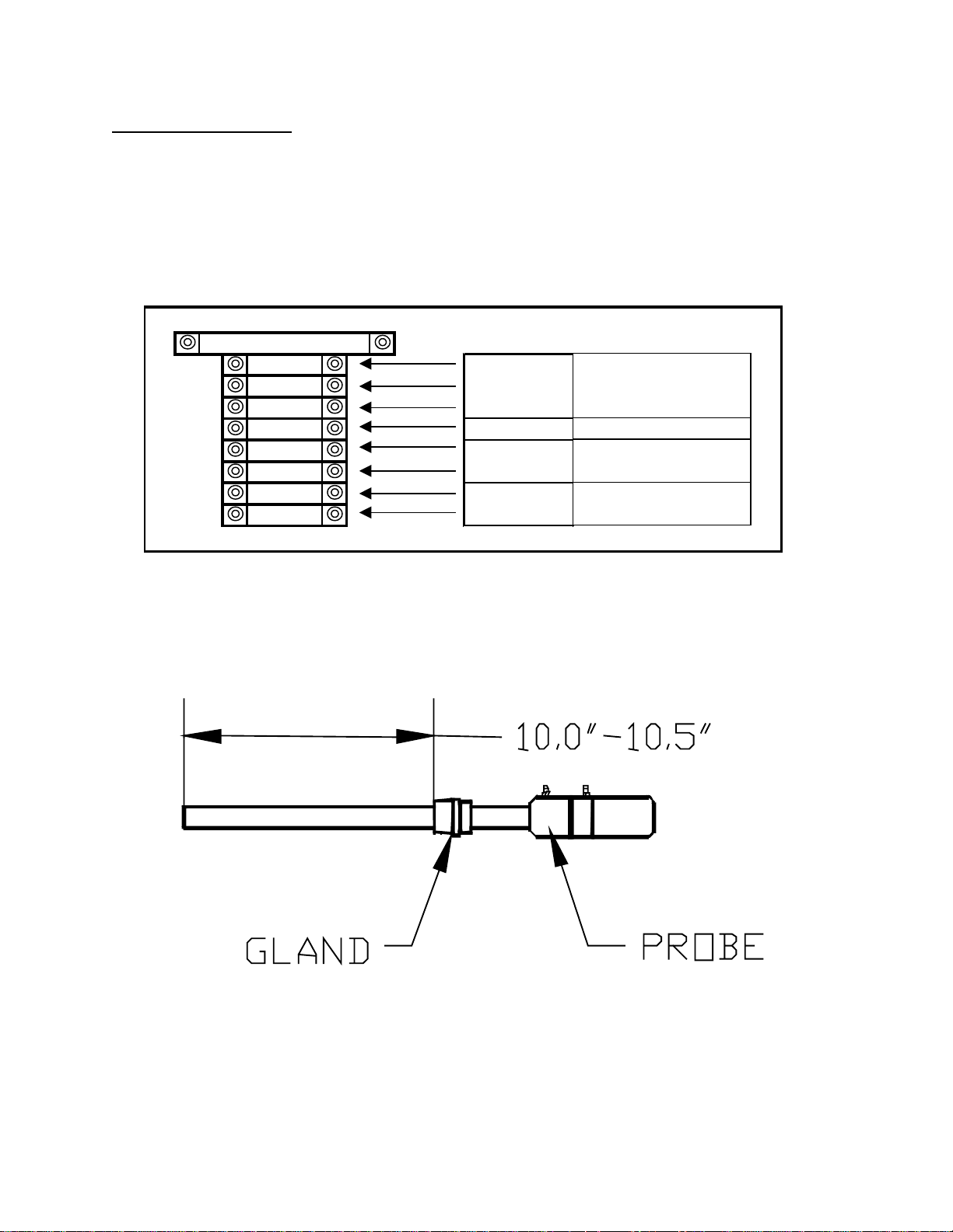
Remove the screw cover on the electrical enclosure box on the side of the main box. Route the
green “S” Type thermocouple wire and the black and white sensor wire (for connection to the
probe) through the access hole at the bottom of the box. Route the power wire (110VAC ONLY)
in through the same hole, and connect it to the terminal block according to the diagram below.
Tighten the wire clamp at the electrical access hole and replace the screw cover to the electrical
enclosure box.
2.0 AMP
1000 Line
1002 Neutral
GND Ground
SPARE N/A
1141 Positive
1151 Negative
1331 Positive
1341 Negative
Host Communications
110VAC
1 PHASE
50-60 HZ
UNUSED
(RS 485)
4-20mA OUTPUT
(0-25% O2)
Insert the probe into the coupling at the base of the large box. It is important that the probe is
inserted at the correct depth to allow proper heating and prevent damage to the ceramic
well inside the unit. There should be between 10.0” and 10.5” between the bottom of the
adjustable 1” NPT gland and the end of the probe (see sketch below).
Page 3

Once the probe has been inserted into the heater, make the necessary electrical connections at the
head of the probe. The green thermocouple wire from the electrical enclosure box should be
attached to the thermocouple connection at the head of the probe (Positive (+) = Black and
Negative (-) = Red). The sensor wire should also be attached to the probe (Positive (+) = Black
and Negative (-) = White).
This unit has been pre-configured and tested prior to shipment. To maximize the accuracy and
longevity of the HP2000, it is recommended that the unit be operated at 1500°F. This set point
has pre-configured in the settings that have already been entered into the controller prior to
shipment.
Plumbing Connections
The sample gas can be transported from the sample port to the instrument using silicone tubing at
a rate between 4.0 and 5.0 SCFH. The sample should routed in the following path to maintain its
integrity and prevent contamination:
1. Furnace / Sample Port → Filter Inlet
2. Filter Outlet → Pump Inlet
3. Pump Outlet → Flow Meter Inlet
4. Flow Meter Outlet → Probe Burnoff Port
5. HP2000 Vent (Coupling on HP2000) → Vent
In addition to the sample gas, ambient air must also be supplied to the probe. This should be
attached at the fitting labeled “Ref. Air”, and the flow rate should be between 1.0 and 2.0 SCFH.
Operation
The single-line LCD display will allow the user to view temperature and the millivolts that are
being measured from the probe, and also the amount of Oxygen in the sample. The amount of
oxygen can either be expressed as a percentage or in exponential notation. It is also possible to
make adjustments to the settings from this display.
There are six buttons on the display; NEXT, PREV, Left Arrow (←), Up Arrow (↑), CLR, and
ENT. NEXT and PREV will move through the various screens, and the other buttons are used
to make changes to the settings.
Page 4

Entering Values Through the Keypad
Only numeric values may be entered into the HP2000 display. The up arrow will cycle through
the numbers starting with zero. Pressing the left arrow key will move to the next number.
Numbers are entered from left to right. For example, to enter the number 123, the user would
begin with the display showing 0. The user would press the up arrow key once so that a 1 would
be displayed. Pressing the left arrow key once will display a 10. Pressing the up arrow key
twice would display 12. Press the left arrow key once to display a 120, and press the up arrow
key three times to display 123.
Menu List
Note: Screens 1, 2, 11, and 12 are for display purposes only. No values can be entered on these
screens.
1) Oxygen (in %), Probe mV and Probe Temperature
2) Oxygen (in ppm), Probe mV and Probe Temperature
3) Temperature Set Point
4) Alarm Set Point
5) Temperature Mode
6) IP Address
7) Output 1 Exponent
8) Output 2 Exponent
9) Output 1 Full Scale
10) Output 2 Full Scale
11) Information Screen #1
12) Information Screen #2
If there are any questions regarding the operation or setup of this unit, please contact Super
Systems Inc at 1-800-666-4330 for assistance.
Page 5

Screen 1: Oxygen (in %), Probe mV and Probe Temperature
This screen is the default screen for the HP2000. This screen lists the percentage of oxygen on
the left of the screen, the probe temperature (in Fahrenheit or Celsius, depending on the
configuration) on the top right of the screen, and the probe millivolts on the bottom right of the
screen. The values on this screen cannot be modified by the user. Pressing the Next button will
display the next screen, Oxygen (in ppm), Probe mV and Probe Temperature. Pressing the Prev
button will display the previous screen, Information Screen #2.
Screen 2: Oxygen (in ppm), Probe mV and Probe Temperature
This screen will display the oxygen in parts per million on the left of the screen, the probe
temperature (in Fahrenheit or Celsius, depending on the configuration) on the top right of the
screen, and the probe millivolts on the bottom right of the screen. The values on this screen
cannot be modified by the user. Pressing the Next button will display the next screen,
Temperature Set Point. Pressing the Prev button will display the previous screen, Oxygen (in
%), Probe mV and Probe Temperature. Pressing the CLR button at any time will return the user
to the first screen.
Screen 3: Temperature Set Point
Page 6

This screen will display the temperature set point for the HP2000, and it will allow the user to
modify the temperature set point for the HP2000. The HP2000 is pre-configured prior to
shipment with a temperature set point of 1500°F. Note: To maximize the accuracy and longevity
of the HP2000, it is recommended that the unit be operated at 1500°F. To change the
temperature set point, press the up arrow key, ↑. The rightmost character will begin blinking.
Pressing the up arrow key again or pressing the left arrow key, ←, will reset the set point to zero.
Pressing the up arrow key again will increment the number by 1. Example – The following
example will show how to set the temperature set point to 1500. Press the up arrow key once so
that the number 1 is displayed. Press the left arrow key once. The number 10 will now be
displayed with the rightmost number blinking. Press the up arrow key five times so that the
number 15 is displayed. Press the left arrow key twice so that the number 1500 is displayed.
Press the ENT button to set the set point. Pressing the CLR button at any time will return the
user to the first screen without entering any changes. Pressing the Next button will display the
next screen, Alarm Set Point. Pressing the Prev button will display the previous screen, Oxygen
(in ppm), Probe mV and Probe Temperature.
Screen 4: Alarm Set Point
This screen will display the alarm set point and it will allow the user to modify the alarm
setpoint. The alarm setpoint will act as an overtemp alarm, and if this value is reached, the
HP2000 will decrease the amount of heat being generated to a point below the alarm setpoint.
Example – The following example will change the alarm set point to 1700. Press the up arrow
key once so that the rightmost digit is blinking. Press the up arrow key once so that a 1 is
displayed. Press the left arrow key once so that a 10 is displayed. Press the up arrow key seven
times so that a 17 is displayed. Press the left arrow key twice so that a 1700 is displayed. Press
the ENT key to set the changes. Pressing the NEXT key will display the next screen,
Temperature Mode. Pressing the PREV key will display the previous screen, Temperature Set
Point.
Screen 5: Temperature Mode
Page 7

This screen will display the temperature mode and it will also allow the user to change the
temperature mode. The temperature mode can be either Fahrenheit or Celsius. Pressing the up
arrow key will toggle between Fahrenheit and Celsius. Note: The user does not need to press the
ENT button; the change in temperature mode will take effect immediately. The change in
temperature mode does not convert the temperature set point or the alarm set point. These
factors will need to be converted manually once the change has been made. Pressing the CLR
button will return the user to the first screen. Pressing the NEXT key will display the next
screen, IP Address. Pressing the PREV key will display the previous screen, Alarm Set Point.
Screen 6: IP Address
This screen will display the IP address and it will also allow the user to modify the IP address.
Press the ENT key to begin changing the IP address. Once the user has pressed the ENT key,
the rightmost digit of the first three digits of the address will begin to blink. Note: Pressing the
ENT key will highlight the rightmost most digit of each section of the IP address. Pressing the
CLR key will reset the number to zero. Holding down the CLR key will display the first screen
to the user without saving any changes. Example – The following example will show how to set
the IP address of the HP2000 to: 192.168.1.210. Press the ENT key. The rightmost digit of the
first three digits should be blinking. Press the CLR key to reset the number to zero. Press the up
arrow key once, so that a 1 is displayed. Press the left arrow key once. Now a 10 should be
displayed. Press the up arrow key nine times so that a 19 is displayed. Press the left arrow key
once so that a 190 is displayed. Press the up arrow key twice so that a 192 is displayed. Press
the ENT key so that the rightmost digit of the next set of three digits is blinking. Repeat these
steps to enter the rest of the IP address. Once the last section of the IP address has been entered.
Press the ENT key to save the changes. Note: None of the digits should be blinking at this point.
Pressing the NEXT key will display the next screen, Output 1 Exponent. Pressing the PREV
key will display the previous screen, Temperature Mode.
Screen 7: Output 1 Exponent
Page 8

The Output 1 Exponent provides greater detail for the output. The valid range of values is zero
to ten. To change the value, press the up arrow key once so that the number begins blinking.
Pressing the up arrow again will increment the value. Once the desired value has been entered,
press the ENT key to set the value. If a value over ten is entered, the value will revert to the
previous value set. Pressing the NEXT key will display the next screen, Output 2 Exponent.
Pressing the PREV key will display the previous screen, IP Address.
Screen 8: Output 2 Exponent
The Output 2 Exponent provides greater detail for the output. The valid range of values is zero
to ten. To change the value, press the up arrow key once so that the number begins blinking.
Pressing the up arrow again will increment the value. Once the desired value has been entered,
press the ENT key to set the value. If a value over ten is entered, the value will revert to the
previous value set. Pressing the NEXT key will display the next screen, Output 1 Full Scale.
Pressing the PREV key will display the previous screen, Output 1 Exponent.
Screen 9: Output 1 Full Scale
The valid range of values for output 1 full scale is zero to nine thousand nine hundred ninety
nine. To change the value, press the up arrow key once so that the rightmost number begins to
blink. Pressing the up arrow again will increment the value. Pressing the NEXT key will
display the next screen, Output 2 Full Scale. Pressing the PREV key will display the previous
screen, Output 2 Exponent.
Screen 10: Output 2 Full Scale
Page 9

The valid range of values for output 2 full scale is zero to nine thousand nine hundred ninety
nine. To change the value, press the up arrow key once so that the rightmost number begins to
blink. Pressing the up arrow again will increment the value. Pressing the NEXT key will
display the next screen, Output 1 Full Scale. Pressing the PREV key will display the previous
screen, Information Screen #1.
Screen 11: Information Screen #1
This screen is an information screen displaying the Super Systems name as well as the type of
controller with the HP2000. The values on this page cannot be modified. Pressing the NEXT
key will display the next screen, Information Screen #2. Pressing the PREV key will display the
previous screen, Output 2 Full Scale.
Screen 12: Information Screen #2
This screen is an information screen displaying Super Systems location and the phone number.
The values on this page cannot be modified. Pressing the NEXT key will display the next
screen, Oxygen (in %), Probe mV and Probe Temperature. Pressing the PREV key will display
the previous screen, Information Screen #1.
Page 10

Spare Parts List
• CeraGold Probe with “S” T/C Part Number 10138
• Sample Pump Part Number 37134
• 110VAC Heater Part Number 32074
• Large Bowl Filer Part Number 37050
• Filter Element for Bowl Filter Part Number 37051
• 0-2 SCFH Flow Meter Part Number 36013
Revision History
Rev. Description Date
- Initial Release 07/20/06
 Loading...