

Page 1

Operations Manual
HP15
Self-Heated Oxygen
Measurement and Control
System
Please read, understand, and follow these instructions before operating this equipment.
Super Systems, Inc. is not responsible for damages incurred due to a failure to comply with
these instructions. If at any time there are questions regarding the proper use of this product,
please contact us at (800) 666-4330 for assistance.
7205 Edington Drive
Cincinnati, OH 45249
513-772-0060 / 800-666-4330
Fax: 513-772-9466
www.supersystems.com
HP 15 Manual Rev A Page 1 of 1
Page 2

Table of Contents
Table of Contents................................................................................................................. 2
General Information .............................................................................................................3
Electrical Connections........................................................................................................... 4
Plumbing Connections .......................................................................................................... 7
HP 15 Screens ..................................................................................................................... 8
Initial Screen.................................................................................................................... 8
Main Menu .......................................................................................................................8
Set Points..................................................................................................................... 8
Temp Mode .................................................................................................................. 9
CO Factor ..................................................................................................................... 9
Hydrogen Factor ........................................................................................................... 9
Pump Control ............................................................................................................. 10
Auto / Manual............................................................................................................. 10
O2 View ..................................................................................................................... 10
Configuration Menu ........................................................................................................ 10
PVT Type ................................................................................................................... 10
Network Settings ........................................................................................................ 11
PID Settings ............................................................................................................... 11
Loop PID Settings – Page 1 ..................................................................................... 11
Loop PID Settings – Page 2 ..................................................................................... 12
Loop PID Settings – Page 3 ..................................................................................... 12
Loop PID Settings – Page 4 ..................................................................................... 12
Burn Off Setup............................................................................................................ 13
Analog Input Setup ..................................................................................................... 13
Analog Input Settings – Page 1 ................................................................................ 13
Analog Input Settings – Page 2 ................................................................................ 14
Analog Input Settings – Page 3 ................................................................................ 14
Analog Output Setup................................................................................................... 15
Analog Output Settings – Page 1.............................................................................. 15
Alarms ....................................................................................................................... 15
Alarm Settings - Page 1 ........................................................................................... 15
Alarm Settings – Page 2 .......................................................................................... 16
Alarm Settings – Page 3 .......................................................................................... 17
Over Temp Alarm........................................................................................................ 17
SSi Information Screen................................................................................................ 17
Spare Parts List.................................................................................................................. 18
Appendix 1 – Factory Defaults ............................................................................................ 19
Universal Defaults........................................................................................................... 19
Carbon PVT Defaults....................................................................................................... 20
Dewpoint PVT Defaults ................................................................................................... 20
Oxygen PVT Defaults ...................................................................................................... 20
Probe mV PVT Defaults ................................................................................................... 21
Probe Redundancy PVT Defaults...................................................................................... 21
Simple Nitrider PVT Defaults ........................................................................................... 22
Dual Loop PVT Defaults .................................................................................................. 22
Revision History ................................................................................................................. 23
HP 15 Manual Rev A Page 2 of 2
Page 3

General Information
The HP15 system includes two main enclosures. The first contains the heater and the Gold
Probe and is painted with a heat resistant black paint. The second is the blue electrical control
panel. Proper operation of this system requires that these two enclosures be wired to each
other to allow the heater to be controlled by the electrical enclosure. For detailed information
regarding the connections between the enclosures, please refer to the E
section of this manual.
lectrical Connections
HP 15 Manual Rev A Page 3 of 3
Page 4
Electrical Connections
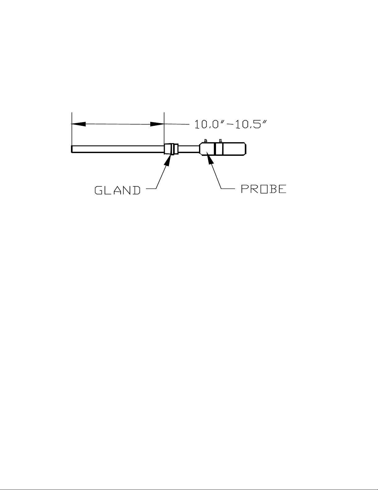
Insert the probe into the coupling at the base of the large box. It is important that the
probe is inserted at the correct depth to allow proper heating and prevent damage
to the ceramic well inside the unit. There should be between 10.0” and 10.5” between the
bottom of the adjustable 1” NPT gland and the end of the probe (see sketch below).
Once the probe has been inserted into the heater, make the necessary electrical connections at
the head of the probe. The green thermocouple wire from the electrical enclosure box should
be attached to the thermocouple connection at the head of the probe (Positive (+) = Black and
Negative (-) = Red). The sensor wire should also be attached to the probe (Positive (+) =
Black and Negative (-) = White).
This unit has been pre-configured and tested prior to shipment. To maximize the accuracy and
longevity of the Heated Probe, it is recommended that the unit be operated at 1500°F. It is
also possible to configure the HP to match the temperature of your furnace.
HP 15 Manual Rev A Page 4 of 4
Page 5
Inside Electrical Enclosure
r
A
A
;
6.0 AMP
;
1000
;;
1002
;;
;;
1003
;;
;
1103
;
1601
;
1602
;
1621
;
1622
;
1681
;
1682
;
1060
;;
1070
;;
;
1320
;
1330
;
1340
;
1641
;
1002
;
GND
;;
;
;
;
;
;
;
;
;
;
;
;
;
;
;
;
;
6 Amp Circuit Breaker
Incoming Customer 110VAC (Line)
Incoming Customer 110VAC (Neutral)
110VAC (Neutral) To Heate
110VAC (Line) to Heater Enclosure
110VAC (Switched Line) to Heater Enclosure
Enriching Gas Contact #1
Enriching Gas Contact #2
Dilution Air Contact #1
Dilution Air Contact #2
Alarm Contact #1
Alarm Contact #2
24VDC (Negative)
24VDC (Positive)
Dry Contact for Sample Inhibit
Dry Contact for Probe Burn-Off
Dry Contact Common
Pump Terminal
110VAC (Neutral) - Spare
Incoming Customer 110VAC (Ground)
;
1021
;
1031
;
1041
;
1350
;
1360
;
1380
Host Communications connect to the Host Computer.
nalog Output #1 is the 4-20mA signal for Process Variable Retransmission.
nalog Output #2 is the 4-20mA signal for Temperature Control (Optional).
;
;
;
;
;
;
RS485 Host Communications Shield
RS485 Host Communications RT- (Negative)
RS485 Host Communications RT+ (Positive)
Analog Output Common (Positive)
Analog Output #1 (Negative)
Analog Output #2 (Negative)
Inside Heater Enclosure
;
1003
;
1002
;
1103
;;
;;
;;
;
;
;
Incoming 110VAC (Line) from Electrical Enclosure
Incoming 110VAC (Neutral) from Electrical Enclosure
Incoming 110VAC (Switched Line) from Electrical Enclosure
HP 15 Manual Rev A Page 5 of 5
Page 6

1. Connect incom ing 120VAC to the Electrical E nclosure:
110 VAC Line Terminal 1000
110 VAC N eutral Terminal 1002
110 VAC G round Terminal GN D
2. Connect Electrical Enclosure to Heater Enclosure:
3. Connect "S" Type Thermocouple wire from P robe to Model 9120 Controller in Electrical Enclosure
4. Connect Millivolt wire from P robe to M odel 9120 Controller in Electrical Enclosure
5.
(Optional)
6.
(Optional)
7.
(Optional)
Electrical Heater
Terminal 1003 Terminal 1003
Terminal 1002 Terminal 1002
Terminal 1103 Terminal 1103
Probe M odel 9120
+ T'CPLE (Black) Terminal 30
- T'CP LE (R ed ) Term ina l 29
Probe M odel 9120
+ SENSOR Terminal 32
- SE NS OR Terminal 31
Connect Furnace Thermocouple to Model 9120 Controller in Electrical Enclosure
Probe M odel 9120
+ T'CPLE Term inal 28
- T'CPLE Terminal 27
Connect RS485 Communications to H ost Com puter
Electrical Host Computer
Terminal 1021 Shield
Terminal 1031 RTTerminal 1041 RT+
Connect Enriching Gas Contact
Electrical (Custom er)
Terminal 1601 T.B.D
Terminal 1602 T.B.D
8.
(Optional)
9.
(Optional)
10.
(Optional)
11.
(Optional)
12.
(Optional)
13.
(Optional)
Connect Dilution A ir Contact
Electrical (Custom er)
Terminal 1621 T.B.D
Terminal 1622 T.B.D
Connect Dilution A ir Contact
Electrical (Custom er)
Terminal 1681 T.B.D
Terminal 1682 T.B.D
Connect Dry Contact for Sam ple Inhibit
Electrical (Custom er)
Terminal 1320 T.B.D
Terminal 1340 T.B.D
Connect Dry Contact for Probe Burnoff
Electrical (Custom er)
Terminal 1330 T.B.D
Terminal 1340 T.B.D
4-20m A O utput for Process Variable Retransm ission
Electrical (Custom er)
Terminal 1350 T.B.D +
Terminal 1360 T.B.D -
4-20m A O utput for Temperature Control
Electrical (Custom er)
Terminal 1350 T.B.D +
Terminal 1380 T.B.D -
HP 15 Manual Rev A Page 6 of 6
Page 7

Plumbing Connections
The sample gas can be transported from the sample port on the furnace to the bottom of the
external filter on the side of the electrical enclosure using silicone tubing. The sample flow
should be between 4.0 and 5.0 SCFH. Silicone tubing should also connect the ports on the side
of the electrical enclosure to the probe in the heater enclosure. Connect tubing from the fitting
on the electrical enclosure marked “To Probe Reference” to the “Ref. Air” port on the probe. A
connection should also be made between the “To Burnoff Port” fitting and the “B.O.” fitting on
the probe. There is a barb fitting on the stainless steel well on the heated probe. This is the
vent, which needs to be routed to an appropriately safe location.
HP 15 Manual Rev A Page 7 of 7
Page 8

HP 15 Screens
Initial Screen
The first screen to be displayed when the HP is powered up is the initial
screen, which will display a combination of: Oxygen, Carbon, millivolts, dew
point, temperature, setpoint, percent output, relay status, and pump status
depending on the selected process variable type.
The first section below the Super Systems Inc logo will display the process
variable type (PVT). The PVT can be: Oxygen, Carbon, Dewpoint, or
millivolts. See the section
information on how to change the PVT type.
The second section (Millivolts:) will display the probe’s current millivolt value.
The third section will display the probe’s current temperature, as well as the
current setpoint. See the section
change the setpoints.
The last section will display the Loop 1 and Loop 2 output percentages. An
A or an M will be displayed next to the output percentage to let the user know if Loop 1 or
Loop 2 is in automatic (A) or manual (M) mode. The “Pump” area will let the user know if the
pump status is on or off. The “Relays” area, which is directly above the Menu button, will
display the energized relays. The number corresponds to the relay in the panel. If a number is
displayed, then that specific relay in the panel is energized. If a number is not displayed, then
that specific relay in the panel is not energized. The Menu button will display the main menu.
Configuration Menu
Set Points
→
PVT Type
for more information on how to
for more
Main Menu
The main menu displays eight buttons, from which the user will be able to set
up the HP 15 instrument. The Exit button will return the user to the initial
screen.
Set Points
Two setpoints are initially displayed on the
screen: Loop 1 and Alarm. To change the
temperature setpoint or the alarm setpoint,
touch the setpoint value, which will display
the numeric keypad.
Enter the new setpoint value and press the
ENT button to set the setpoint. Press the
ESC button to cancel the change.
The Remote Setpoint Setup button will display the Remote Setpoint
screen, which will allow the user to set up a remote setpoint for Loop 2,
which is generally the temperature loop. There are six buttons to choose
from for a remote setpoint: None, Slave 1 PV, Slave 2 PV, Slave 1 SP,
Slave 2 SP, or Input 3 Value. Pressing the desired button will set the setpoint to the
specified source. When None is pressed, the setpoint that was set from the previous screen
HP 15 Manual Rev A Page 8 of 8
Page 9

will be used. To change the hysteresis, click on the Hysteresis button and
enter the new hysteresis value from the numeric keypad. The More >>>
button will allow the user to set the setpoint for the selected PVT (Dew point,
Carbon, Oxygen, or millivolts). The <<< More button will return the user to
the previous screen. The Menu button will return the user to the main menu.
Temp Mode
The temperature mode screen displays the current temperature mode
(Fahrenheit or Celsius) as well as the current setpoint. To
change the mode to Celsius, press the Switch to Celsius
button. To change the mode to Fahrenheit, press the
Switch to Fahrenheit button. When the temperature
mode is changed, the setpoint will be converted
automatically. This is a safety precaution to prevent setting
extremely high setpoints when switching to the Celsius scale. The setpoint
can always be changed from the
Set Points
menu.
CO Factor
The COF factor allows you to make adjustments that will
allow the controller to match the results obtained when
measuring shim stock. If the controller set point and the
process variable are the same, but you are not attaining the
desired surface Carbon, you can make the adjustment with
the CO Factor to increase the amount of surface Carbon available to the parts.
If you lower the CO factor, it immediately lowers the % Carbon process
variable. This will cause the controller to add more enriching gas--- raising the
process variable until once again the process variable and the set point match.
Conversely, raising the CO Factor will cause the process variable to read
higher, shutting down the enriching gas solenoid (possibly turning on the air
dilution solenoid) causing the % Carbon process variable to begin to lower (NOT ADDING
ENRICHING GAS) until the set point and process variable match. To change the CO Factor,
enter the new factor and press the ENT button. Pressing the ESC button will not set the new
CO Factor.
just for display purposes. The CO Factor will not be set to 0.
Note: when the ESC button is pressed, the display will show a 0; however, this is
Hydrogen Factor
The Hydrogen factor is very similar to the CO factor, as explained above.
The instrument will perform its calculations based on a theoretical amount of
carbon or hydrogen. However, the actual amounts of carbon or hydrogen
will probably be different from the theoretical amounts that the instrument is
using to perform the calculations. Changing the CO factor or the Hydrogen
factor will allow the instrument to make its calculations based on the actual
amount of carbon or hydrogen, which will make the calculations more
accurate. This screen has the same functionality as the CO Factor screen.
HP 15 Manual Rev A Page 9 of 9
Page 10

Pump Control
This screen will allow the user to manually turn the pump on or off. Press
the On button to turn the pump on. Press the Off button to turn the pump
off. The “Low Temperature Pump Cutoff” section will allow the user to set a
low temperature that will shut the pump off if the specified temperature is
reached. Press the value and enter the desired pump cutoff setpoint.
Auto / Manual
The “Loop 1 Out:” section displays the output percentage of
Loop 1, along with the current mode of the loop – Auto for
automatic, Man for manual. To switch the mode of the
loop to automatic, press the Automatic Control button.
To switch the mode of the loop to manual, press the
Manual Control button. When the loop is in manual
mode, the output percentage can be changed by pressing the output
percentage value and entering the new value from the numeric keypad that is
displayed.
The “Loop 2 Out:” section displays the output percentage of Loop 2, along
with the current mode of the loop – Auto for automatic, Man for manual. To
switch the mode of the loop to automatic, press the Automatic Control
button. To switch the mode of the loop to manual, press the Manual
Control button. When the loop is in manual mode, the output percentage can be changed by
pressing the output percentage value and entering the new value from the numeric keypad that
is displayed.
O2 View
This feature is not yet implemented.
Configuration Menu
The Config Menu button will display the configuration menu. The
Configuration menu displays six buttons that will allow the user to
configure the HP15. The Exit button will return the user to the main
menu.
PVT Type
This screen will allow the user to set the PVT type. The
currently selected PVT type will be listed at the top of the screen. Press the
Carbon button to set the PVT type to Carbon. Press the Dew Point button
to set the PVT type to Dew Point. Press the
Oxygen button to set the PVT type to Oxygen.
Press the Millivolts button to set the PVT type
to Millivolts. Press the Simple Nitrider button
to set the PVT type to Simple Nitriding. Press
the Dual Loop button to set the PVT type to
Dual Loop. Since changing the PVT type will set
HP 15 Manual Rev A Page 10 of 10
Page 11

default values for that type, certain settings may be lost. When the PVT type is changed, the
user will have to confirm the changes. Pressing the Yes button will change the PVT type, and
pressing the No button will not change the PVT type. The Menu button will return the user to
the configuration menu.
Network Settings
The Network Settings screen will allow the user to set up the network
addresses for the HP15. Each screen – IP Address, Netmask, and Gateway
– will function identically. The IP Address button will allow the user to
change the IP address of the device. The Netmask
button will allow the user to change the Netmask of the
device. The Gateway button will allow the user to
change the gateway of the device. To change a specific
section of an address, press the value and enter the new
value on the numeric keypad.
PID Settings
This menu screen will allow the user to select which loop to change the PID
settings for. Press the Loop 1 PID Settings button to change the PID
settings for Loop1, or press the Loop 2 PID Settings button to change the
PID settings for Loop 2. The Exit button will return the user to the
configuration menu screen. The screens for the Loop 1 PID settings and
Loop 2 PID settings function identically.
Loop PID Settings – Page 1
From this screen, the user can modify the proportional
band, reset, rate, and cycle time. To edit any of these
values, press the value and enter the new value from the
numeric keypad that is displayed. The More >>> button
will display Page 2 of the PID Settings menu. The Menu
button will display the
PID Settings
menu.
HP 15 Manual Rev A Page 11 of 11
Page 12

Loop PID Settings – Page 2
From this screen, the user can modify the control loop output, integral
preset, control low limit, control high limit, and the loop mode. To edit the
control loop output, integral preset, control low limit, or the control high
limit, press the value and enter the new value from the numeric keypad
that is displayed. The currently selected loop mode will be displayed in the
box. To change the loop mode, press the up arrow next to the displayed
mode. This will display the available modes in the form of buttons:
Dual Reverse (Gas/Air, Heat/Cool)
Single Reverse (Heat)
Dual Direct (Dew Point)
Dual Reverse (Cool)
Press the button for the desired mode. The <More
button will display Page 1 of the PID Settings menu. The
More> button will display Page 3 of the PID Settings
menu. The Menu button will display the
PID Settings
menu.
Loop PID Settings – Page 3
From this screen, the user can modify the auto PID setting, as well as whether
or not the high limit shuts down the control for each input. To turn the auto
PID on, press the On button. To turn the auto PID off, press the Off button.
The current status of the auto PID will be displayed. To modify whether the
high limit shuts down the control for Input 1, 2, or 3, press the Toggle button
for the desired input. For example, to have the high limit shut down control
for Input 1, press the top Toggle button; to have the high limit shut down
control for Input 3, press the bottom Toggle button. The <More button will
display Page 2 of the PID Settings menu. The More> button will display Page
4 of the PID Settings menu. The Menu button will display the
menu.
Loop PID Settings – Page 4
From this screen, the user can modify the zero setpoint shuts down control
value, as well as the set point change limit value. Whether or not a zero
setpoint shuts down control will be displayed above the Yes/No buttons.
To allow a zero setpoint to shut down control, press the
Yes button. To not allow a zero setpoint to shut down
control, press the No button. The current setpoint
change limit is displayed in the box. To change the
setpoint change limit, press the up arrow next to the
displayed value. This will display eight buttons that will
allow the user to change the setpoint change limit:
Off
80 %
70 %
PID Settings
HP 15 Manual Rev A Page 12 of 12
Page 13

60 %
50 %
40 %
30 %
20 %
Press the button for the desired setpoint change limit. The <<< More button will display Page
3 of the PID Settings menu. The Menu button will display the
PID Settings
menu.
Burn Off Setup
From this screen, the user can modify the burn off time in seconds,
recovery wait time in seconds, interval in minutes, minimum millivolts, and
the maximum temperature values. The user can also
start a manual burnoff from this screen. To modify the
burn off time, recovery wait time, interval, minimum
millivolts, or the maximum temperature value, press the
value and enter the new value from the numeric keypad
that is displayed. To start a manual burnoff, press the
Start Manual Burn Off button. While a burnoff is in
progress, the burnoff in progress screen will be displayed.
The current sequence number and the time remaining in
seconds will be displayed. The Close button will close
down the screen.
Note: While the burnoff in progress
screen may be closed, the burnoff will still be in progress, and another manual
burnoff may not be started until the current burnoff is finished
.
Analog Input Setup
This menu screen will allow the user to set up the analog input settings for
Input 1, 2, or 3. To change the analog inputs settings for Input 1, press
the Analog Input 1 Settings button. To change the analog inputs
settings for Input 2, press the Analog Input 2 Settings button. To
change the analog inputs settings for Input 3, press the Analog Input 3
Settings button. The screens for the analog input settings 1, 2, and 3
function identically. The Exit button will return the user
to the configuration menu.
Analog Input Settings – Page 1
From this screen, the user can modify the input type,
filter, initial scale, full scale, and decimal point location.
The current input type is displayed in the box. To change
the input type, press the down arrow next to the displayed value. This action
will display twenty buttons that will allow the user to change the input type:
Type B
Type C
Type E
Type J
Type K
Type N
HP 15 Manual Rev A Page 13 of 13
Page 14
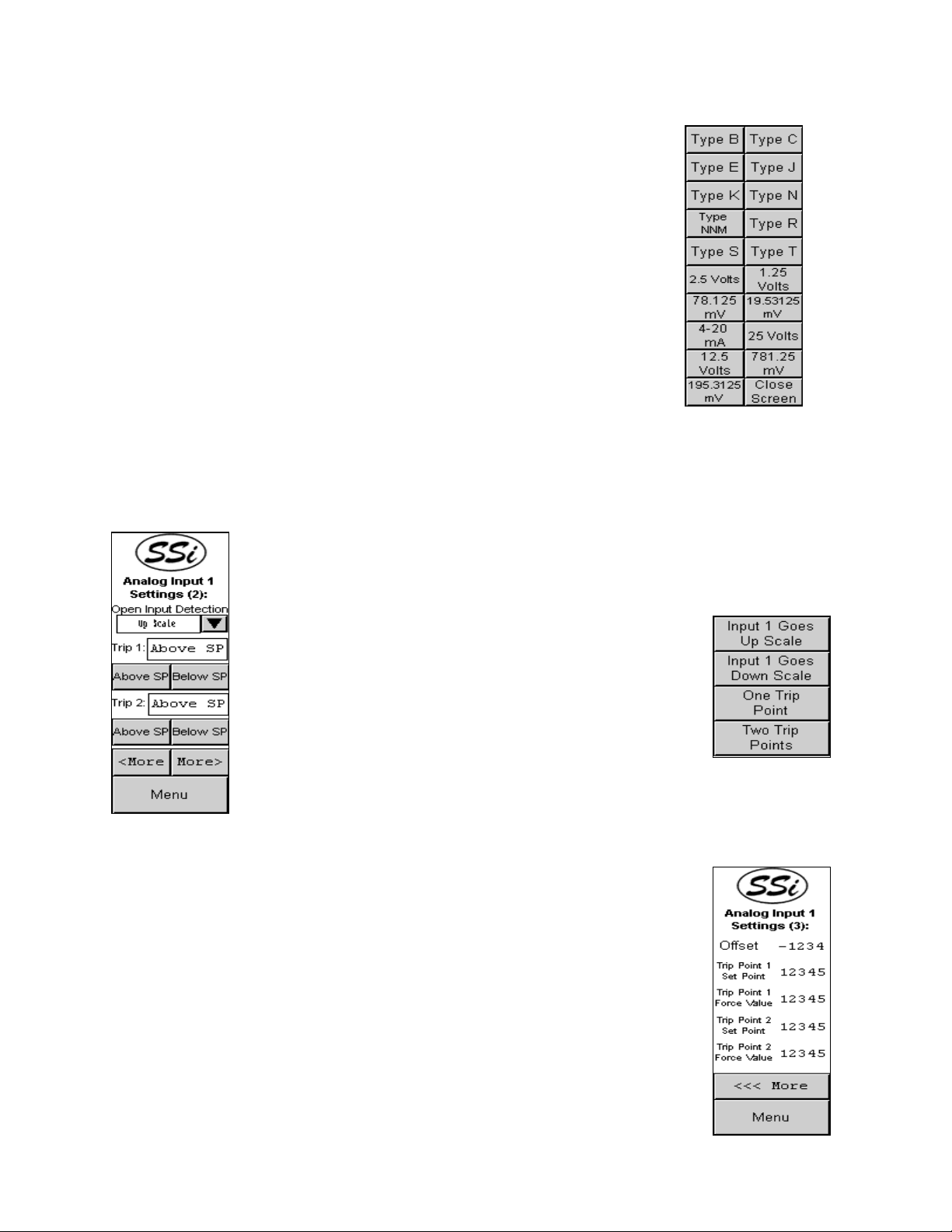
Type NNM
Type R
Type S
Type T
2.5 Volts
1.25 Volts
78.125 mV
19.53125 mV
4-20 mA
25 Volts
12.5 Volts
781.25 mV
195.3125 mV
Close Screen
Press the button for the desired input type. To change the filter, initial
scale, full scale, or decimal point location, press the value and enter the new value from the
numeric keypad that is displayed. The More >>> button will display Page 2 of the analog
input settings menu. The Menu button will display the
Analog Input Setup
menu.
Analog Input Settings – Page 2
From this screen, the user can modify the open input direction, trip 1 value,
and the trip 2 value. The current open input direction value is displayed in the
box. To modify the open input direction, press the down arrow next to the
displayed value. This will display four buttons that will allow the user to
change the open input direction:
Input X Goes Up Scale
Input X Goes Down Scale
One Trip Point
Two Trip Points
Press the button for the desired open input direction. To
set the Trip 1 value to Above Setpoint, press the Above SP
button under the Trip 1 value. To set the Trip 2 value to
Above Setpoint, press the Above SP button under the Trip 2 value. To set
the Trip 1 value to Below Setpoint, press the Below SP button under the Trip
1 value. To set the Trip 2 value to Below Setpoint, press the Below SP button under the Trip
2 value. Pressing the <More button will display Page 1 of the analog inputs settings menu.
Pressing the More> button will display Page 3 of the analog input settings
menu. The Menu button will display the
Analog Input Setup
menu.
Analog Input Settings – Page 3
From this screen, the user can modify the offset, trip point 1 set point, trip
point 1 force value, trip point 2 setpoint, and the trip point 2 force value. To
edit any of these values, press the value and enter the new value from the
numeric keypad that is displayed. Pressing the <<< More button will
display Page 2 of the analog input settings menu. The Menu button will
display the
Analog Input Setup
menu.
HP 15 Manual Rev A Page 14 of 14
Page 15

Analog Output Setup
This screen will allow the user to set up the analog output settings for output
1 or 2. To change the analog output settings for output 1, press the Analog
Output 1 Settings button. To change the analog output settings for output
2, press the Analog Output 2 Settings button. The screens for the analog
output settings function identically for outputs 1 and 2. The Menu button will
return the user to the configuration menu.
Analog Output Settings – Page 1
From this screen, the user can modify the analog output
assignment, the exponent, and the full-scale values. To
select a new analog output assignment, press the down
arrow next to the assignment. This will display a screen with
18 buttons to choose from:
PV 1 retrans
Loop 1 inc
Loop1 dec
Loop 1 combo
PV 2 retrans
Loop 2 inc
Loop 2 dec
Loop 2 combo
Disassociation
Nit_Pot
Hydrogen
- (Invalid Option)
Input 1 retrans
Loop 2 retrans
Loop 3 retrans
O2 offset log
PV 1 retrans w/ expo range
The Close Screen button will close the screen without selecting a new assignment. Press the
new assignment button to select it. To modify either the exponent or the full scale, press the
value and enter the new value from the numeric keypad that is displayed. The Back button
will display the analog output setup menu screen.
Alarms
This screen will allow the user to set up Alarm 1, Alarm 2, or Alarm 3. To
set up Alarm 1, press the Alarm 1 Settings button. To set up Alarm 2,
press the Alarm 2 Settings button. To set up Alarm 3, press the Alarm
3 Settings button. The screens for the alarms will function identically for
Alarms 1, 2, and 3.
The over temperature alarm will now read “Overtemp Alarm 1”
Note: Alarm 1 is a dedicated over temperature alarm.
.
Alarm Settings - Page 1
This screen will allow the user to set the alarm source, alarm action, and
the alarm set point. To set the alarm source, press the up arrow next to
HP 15 Manual Rev A Page 15 of 15
Page 16
the source. This will display ten buttons from which the user can select
the alarm source:
PV1
PV2
PV3
Input 1
Input 2
Input 3
% Output 1
% Output 2
% Output 3
Back Screen
The current alarm source will be displayed at the
bottom of the screen. The Back Screen button
will display the Alarm Settings page 1 menu screen.
To set the alarm action, press the up arrow next to
the action. This will display a screen with seven
buttons from which the user can select the alarm action:
Process High
Process Low
Band Normally Open
Band Normally Closed
Deviation NO
Deviation NC
Back Screen
The current alarm action will be displayed at the top of the screen. The
Back Screen button will display the Alarm Settings page 1 menu
screen. To set the alarm setpoint, press the value and enter the new
setpoint on the keypad displayed. Pressing the More >>> button will
display page 2 of the Alarm Settings menu. Pressing the Menu button
will display the
Alarms
menu.
Alarm Settings – Page 2
This screen will allow the user to set the smart
alarm and whether or not a 0 setpoint blocks the
alarm. To enable the smart alarm, press the
Enable button under the smart alarm status. To
disable the smart alarm, press the Disable button under the smart alarm
status. To ensure that a 0 setpoint will block the alarm, press the On
button below the status. To ensure that a 0 setpoint will not block the
alarm, press the Off button below the status. Pressing the <Back button
will display the page 1 of the Alarm Settings menu. Pressing the More>
button will display page 3 of the Alarm Settings menu. Pressing the Menu
button will display the
Alarms
menu.
HP 15 Manual Rev A Page 16 of 16
Page 17

Alarm Settings – Page 3
This screen will allow the user to set the hysteresis and the on delay time
for the alarm. To set the hysteresis, press the value and enter the new
hysteresis value from the calculator. To set the On delay time, press the
value and enter the new On delay time from the calculator. Pressing the
<<<Back button will display page 2 of the Alarm Settings menu. Pressing
the Menu button will display the
Alarms
menu.
Over Temp Alarm
If at any time the alarm setpoint is exceeded, the over temp alarm screen will
be displayed on the screen. This screen will remain displayed until the
acknowledge button, ACK, is pressed.
SSi Information Screen
On any screen where the Super Systems Inc logo is visible, the user will be
able to display the information screen for the HP 15. Press the logo to
display the screen. The information screen will display the
Super Systems Inc address and contact information, as well
as the screen version and the firmware version of the 9120.
The user can close out the screen either by pressing the Super Systems Inc
logo again, or by pressing the Close button.
HP 15 Manual Rev A Page 17 of 17
Page 18

Spare Parts List
31125 24 Volt / 1.2 Amp Power Supply
13454 Series 9120 Controller
31292 Operator Interface - Touch Screen
37177 Pump - Sample and Burnoff Air
37020 Pump - Reference Air
20059 Filter with Media
37037 Replacement Filter Media (20 grams)
32074 Heater - 110V / 425 Watt
10138 Ceragold Probe 400 zirconia sensor w/ "S" T/C
HP 15 Manual Rev A Page 18 of 18
Page 19

Appendix 1 – Factory Defaults
Universal Defaults
• Temperature in °F
• All Baud Rates initially 19200 and set for Modbus
• Burnoff time is 90 seconds
• Burnoff recovery wait time is 2 minutes
• Burnoff interval is 12 hours
• Burnoff maximum temperature is 2000 °F
• CO Factor is 200
• Hydrogen factor for Dewpoint calculation is 40%
• Analog to Digital Converter filter time is 8 seconds for all 3 ADCs
• For analog input 1 initial scale is 0, and full scale is 1000
• For analog input 2 initial scale is 0, and full scale is 10000
• For analog input 3 initial scale is 0, and full scale is 10000
• First Process Control Setpoint is set to 0
• First Process Proportional Band is 20%
• First Process Reset for PID control is On
• First Process Rate for PID control is 0
• First Process Output Cycle Time for Control is 16 milliseconds
• First Process Auto/Manual set to Automatic
• First Process Control Load Line or Manual Reset (integral preset) set to 0
• Second Process Control Setpoint is set to 0
• Second Process Proportional Band is 4.4%
• Second Process Reset for PID control is 12
• Second Process Rate for PID control is 216
• Second Process Output Cycle Time for Control is 60 milliseconds
• Second Process Auto/Manual set to Automatic
• Second Process Control Load Line or Manual Reset (integral preset) set to 0
• Start PV for temporary tuning set to 0
• Temporary Proportional band for tuning set to 2%
• Temporary reset for tuning set to On
• Temporary rate for tuning set to 0
• Temporary integral preset for tuning set to 0
• Relay 1 set for loop 2 heat
• Relay 2 set for alarm 1
• Relay 3 set for loop 1 increment (gas)
• Relay 4 set for loop 1 decrement (air)
• Relay 5 fixed by PV type.
• Relay 6 set for Probe Burnoff
• Relay 7 set for Alarm 3
• Relay 8 set for all alarms.
• Alarm 1 setpoint set for 1800
• Alarm 1 is set for analog input 2
• Alarm 1 hysteresis is set for 1
• Alarm 2 setpoint set for 2000
• Alarm 2 is set for analog input 1
HP 15 Manual Rev A Page 19 of 19
Page 20

• Alarm 2 hysteresis is set for 1
• Alarm 3 setpoint set for 2000
• Alarm 3 is set for process variable 2
• Alarm 3 hysteresis is set for 1
• Digital to Analog converter 1 assignment is PV1 retransmit
• Digital to Analog converter 2 assignment is loop 2 increment
• Default IP is 192.168.0.200
Carbon PVT Defaults
• Process variable 1 is carbon
• Process variable 2 is temperature
• Process variable 3 is temperature
• Analog output 1 offset is 0
• Analog output 1 range is 2000
• Analog output 1 offset is 0
• Analog output 1 range is 2000
• First process control low limit is –100
• First process control high limit is 100
• First process control mode is such that setpoint of 0 shuts down and it is in dual mode
• Second process control low limit is 0
• Second process control high limit is 100
• Second process control mode is such a high analog input 2 shuts down
• Analog input 1 full scale is 2500
• Analog input 1 type is 2.5 volts
• Analog input 2 type is S thermocouple
• Analog input 3 type is K thermocouple
Dewpoint PVT Defaults
• Process variable 1 is dewpoint
• Process variable 2 is temperature
• Process variable 3 is temperature
• Analog output 1 offset is 0
• Analog output 1 range is 2000
• Analog output 1 offset is 0
• Analog output 1 range is 2000
• First process control low limit is –100
• First process control high limit is 100
• First process control mode is such that dual direct mode
• Second process control low limit is 0
• Second process control high limit is 100
• Second process control mode is such a high analog input 2 shuts down
• Analog input 1 full scale is 2500
• Analog input 1 type is 2.5 volts
• Analog input 2 type is S thermocouple
• Analog input 3 type is K thermocouple
Oxygen PVT Defaults
• Process variable 1 is carbon
HP 15 Manual Rev A Page 20 of 20
Page 21

• Process variable 2 is temperature
• Process variable 3 is temperature
• Analog output 1 offset is 0
• Analog output 1 range is 2000
• Analog output 1 offset is 0
• Analog output 1 range is 2000
• First process control low limit is 0
• First process control high limit is 100
• First process control mode is such that it is in single reverse
• Second process control low limit is 0
• Second process control high limit is 100
• Second process control mode is such a high analog input 2 shuts down
• Analog input 1 full scale is 1250
• Analog input 1 type is1.25 volts
• Analog input 2 type is S thermocouple
• Analog input 3 type is S thermocouple
• Alarm 3 setpoint is 1.0%
• Alarm 3 type PV1 process low
• Open TC input1 goes down scale
• Relay 3 assignment is loop 1 decrement (gas)
• Relay 4 assignment is loop 1 increment (air)
Probe mV PVT Defaults
• Process variable 1 is Millivolts
• Process variable 2 is temperature
• Process variable 3 is temperature
• Analog output 1 offset is 0
• Analog output 1 range is 2000
• Analog output 1 offset is 0
• Analog output 1 range is 2000
• First process control low limit is –100
• First process control high limit is 100
• First process control mode is such that setpoint of 0 shuts down and it is in dual mode
• Second process control low limit is 0
• Second process control high limit is 100
• Second process control mode is such a high analog input 2 shuts down
• Analog input 1 full scale is 2500
• Analog input 1 type is 2.5 volts
• Analog input 2 type is S thermocouple
• Analog input 3 type is K thermocouple
Probe Redundancy PVT Defaults
• Process variable 1 is probe 1
• Process variable 2 is probe 2
• Process variable 3 is temperature
• Analog output 1 offset is 0
• Analog output 1 range is 200
• Analog output 1 offset is 0
HP 15 Manual Rev A Page 21 of 21
Page 22

• Analog output 1 range is 200
• First process control low limit is –100
• First process control high limit is 100
• First process control mode is such that setpoint of 0 shuts down and it is in dual mode
• Second process control low limit is 0
• Second process control high limit is 100
• Second process control mode is such that it is in single reverse
• Analog input 1 full scale is 2500
• Analog input 2 full scale is 2500
• Analog input 1 type is 2.5 volts
• Analog input 2 type is 2.5 volts
• Analog input 3 type is K thermocouple
• 20 minutes delay time before alarm
• Band +/1 for alarm in millivolts is 10
• Modbus at 9600 baud
Simple Nitrider PVT Defaults
• Process variable 1 is carbon
• Process variable 2 is temperature
• Process variable 3 is temperature
• DAC 1 is set for Hydrogen
• DAC2 is set for Dissociation
• Analog output 1 offset is 0
• Analog output 1 range is 1000
• Analog output 1 offset is 0
• Analog output 1 range is 1000
• First process control low limit is –100
• First process control high limit is 100
• First process control mode is such that setpoint of 0 shuts down and it is in dual mode
• Second process control low limit is 0
• Second process control high limit is 100
• Second process control mode is such that it is in single reverse
• Analog input 1 full scale is 2500
• Analog input 1 type is 2.5 volts
• Analog input 2 type is S thermocouple
• Analog input 3 type is K thermocouple
• host RS232
• Hitech H2 cell at 9600 baud
Dual Loop PVT Defaults
• Alarm 2 setpoint is 2000
• Alarm 3 setpoint is 2000
• Alarm 2 type is input 1 process high
• Alarm 3 type is PV2 process high
HP 15 Manual Rev A Page 22 of 22
Page 23

Revision History
Rev. Description Date MCO #
- Initial Release 06/14/07 N/A
A Updated logo on title page; Changed screen
shots; Added “O2 View” (although this section
is not implemented); Added warning when PVT
type is changed; Added “Alarms” section of
Configuration Menu; Updated “Revision
History” section – Added “MCO #” block; Set
Alarm 1 as the dedicated over temperature
alarm; Added “Factory Defaults” appendix
12/21/07 2055
HP 15 Manual Rev A Page 23 of 23
 Loading...