

Page 1

Gold Probe
Instructions Manual
7205 Edington Drive
Cincinnati, OH 45249
513-772-0060 800-666-4330
Fax: 513-772-9466
www.supersystems.com
Page 2

INTRODUCTION .................................................................................................................... 2
SPECIFICATIONS.................................................................................................................. 2
CHARACTERISTICS .............................................................................................................. 3
BASIC OPERATING THEORY ................................................................................................ 4
INSTALLATION ..................................................................................................................... 5
MAINTENANCE .................................................................................................................... 6
Table of Contents
Furnace conditioning ........................................................................................................ 6
Probe conditioning: ........................................................................................................... 7
TROUBLE SHOOTING ........................................................................................................... 8
Probe troubleshooting: ..................................................................................................... 8
CONTROL SYSTEMS ............................................................................................................. 9
WARRANTY ......................................................................................................................... 11
NOTES ................................................................................................................................ 12
CARBON vs. DEW POINT WITH TEMPERATURE ............................................................... 13
CARBON vs. MILLIVOLTS WITH TEMPERATURE .............................................................. 14
SSi Gold Probe Manual Rev C
1
Page 3
Useful %C Range- .01 to 1.6%
Temperature Range- 1200F to 2000F
(649C to 1093C)
Stability- within +/- 1 mVDC
Impedance- less than 10 kohms @ 1700F
(927C)
Mounting- 1" (25.4mm) NPT
Sheath dia.- 0.84" (1/2" pipe)
(21mm, 13mm pipe)
Useful output- 0 to 1250 mVDC
Probe Specifications
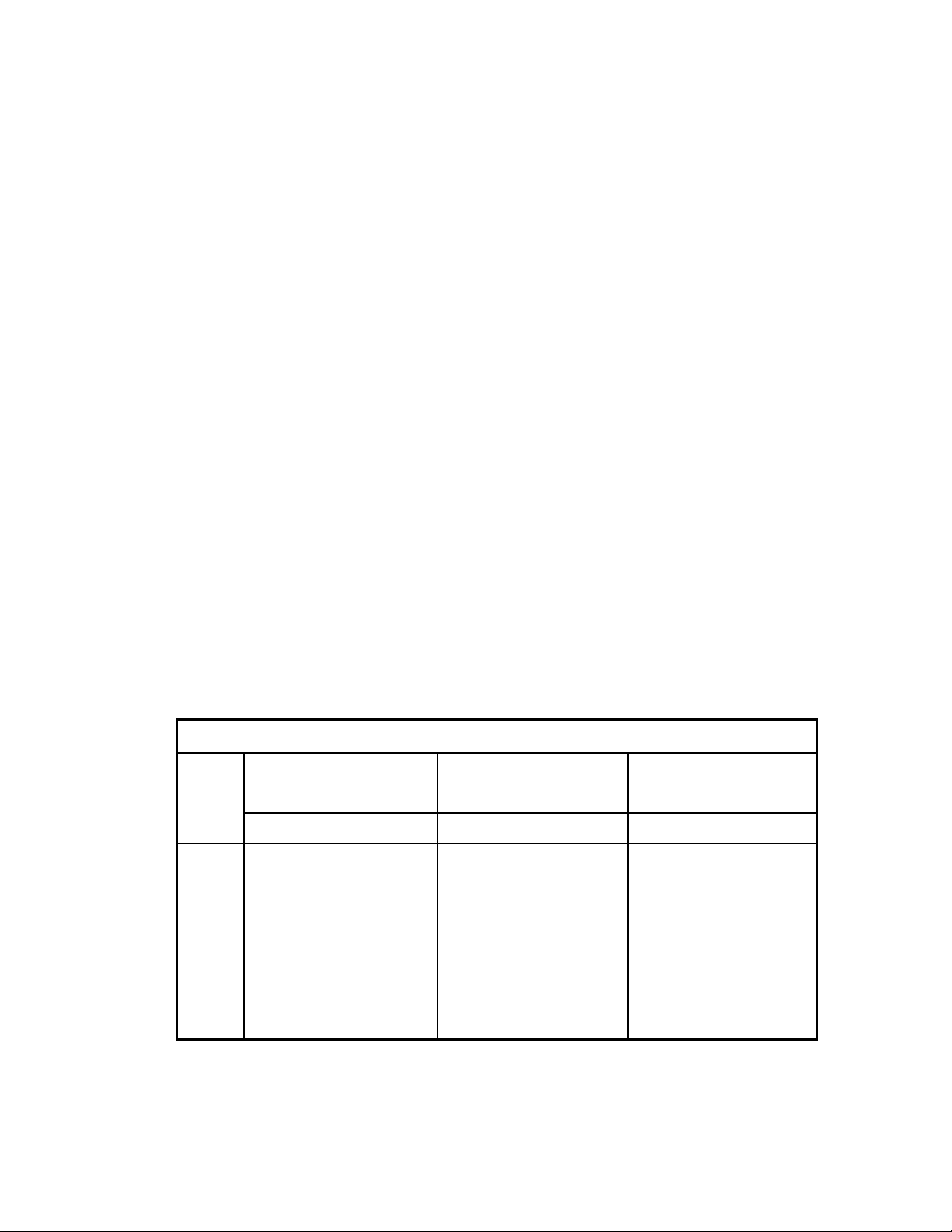
Model
Nominal Insertion
Length
Nominal Overall Length
Boxed Weight
INCHES
MILLIMETERS
INCHES
MILLIMETERS
POUNDS
KILOGRAMS
GP133
14.3
364.0
20.8
528.0
3.6
1.8
GP205
20.5
521.5
27.2
690.0
4.0
1.8
GP277
27.7
705.0
34.3
871.0
4.6
2.1
GP330
33.0
840.0
39.5
1003.0
5.4
2.4
GP373
36.8
936.5
43.4
1101.5
5.8
2.6
GP420
42.0
1069.0
48.3
1228.0
6.4
2.9
GP480
48.0
1221.5
54.3
1379.5
6.8
3.1
INTRODUCTION
SPECIFICATIONS
Thank you for selecting the Gold Probe™ for your atmosphere control application.
The Gold Probe™ represents “state of the art” in carbon sensor technology. It has been
designed for use in carbon control systems as applied to both carbon control in
atmosphere furnaces and dew point in endothermic generators.
The Gold Probe™, with its unique measuring electrode construction, is the product of a
team of design and application engineers, each with over twenty years of atmosphere
control experience. The SSi engineering team has long recognized that the sensor is the
most critical component in the atmosphere control system and has traditionally been
the weakest link. Now, reliability, repeatability and accuracy are assured with the
inclusion of the Gold Probe™ in
your
control system.
SSi Gold Probe Manual Rev C
2
Page 4
CHARACTERISTICS
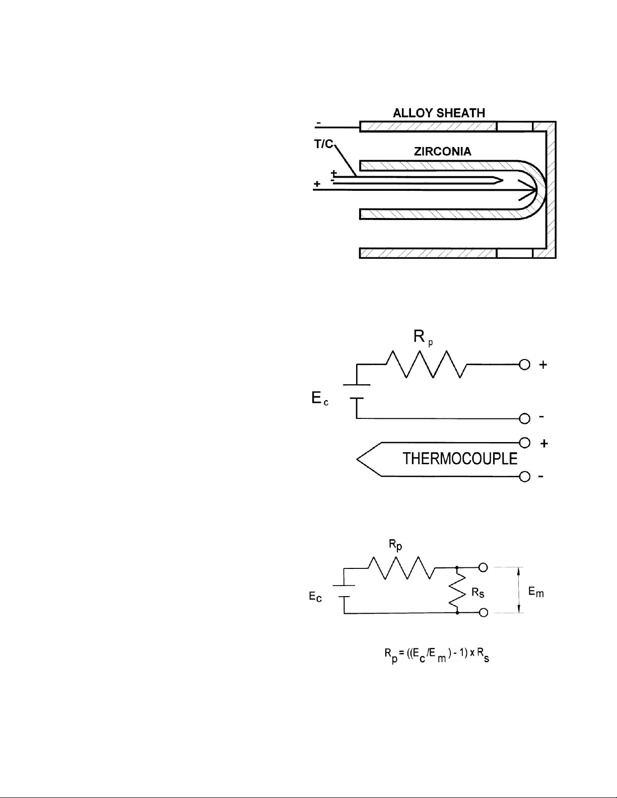
The typical zirconia carbon sensor consists of a
closed end tube with the sensing portion at the tip.
The entire tube may be zirconia or there may be a
slug of zirconia cemented in the tip. Fig.1
illustrates the Gold Probe™ design with details
omitted for clarity. The tip of the tube is spring
loaded into contact with the sheath, which also
serves as the outer electrode. The inner electrode
is spring loaded into contact with the inner
zirconia surface. A thermocouple is positioned
close to the inner electrode surface and reference
air bathes the sensing surface.
To the instrument technician, the probe looks like
a battery (see Fig.2.) It displays a voltage, Ec, from
which the carbon potential can be calculated. The
probe thermocouple is shown next to the sensing
electrode.
The value of the internal resistance can be
measured, as shown in Fig. 3, by putting a shunt
resistor across the probe, measuring the resultant
voltage, Em and carrying out the simple calculation
shown.
FIG. 1
FIG. 2
FIG. 3
SSi Gold Probe Manual Rev C
3
Page 5

BASIC OPERATING THEORY
Carbon potential of a conventional furnace
atmosphere is defined as the %C achieved in a
coupon of carbon steel shim stock equilibrated in
the furnace atmosphere. Unfortunately,
equilibration time is long, so it is impossible to
continuously control the atmosphere on the
basis of shim stock measurements. A zirconia
sensor, however, can be used to measure and
control the carbon potential precisely, and on a
continuous basis.
Strictly speaking, the zirconia probe is not
sensing carbon at all. It is an oxygen sensor with
a mVDC output described by Equation (1).
Fortunately, an empirical (experimental)
relationship exists between oxygen
concentration and carbon potential, and this
relationship has been used in carbon control
instruments since the early ‘70’s. The equation
used by most control manufacturers today is
illustrated by Equation (2), which states that
there are only
three
variables affecting the
measured millivoltage. Because the actual
equation used is somewhat complex, it is not
reproduced here. A full description of probe
theory will be found in SSi technical bulletin
T4401 (Zirconia Sensor Theory).
All
competitive probes will invariably agree
within one or two millivolts when exposed to the
same atmosphere under equilibrium conditions.
Differences in values listed by probe vendors
relate to differences in manufacturers’ source
data, but the true value of the zirconia probe is
its repeatability.
ZIRCONIA O2 RESPONSE
Ec = 0.0276TR log (Pf /Pa) millivolts (1)
Zr PROBE ALGORITHM
%C= ( EC , %CO, TR) mVDC (2)
Where: means ‘is a function of’
%C is the carbon potential
%CO is carbon monoxide percentage
TR is the absolute temperature in
degrees
Rankine (deg. F + 460).
and EC is the probe output in millivolts.
SSi Gold Probe Manual Rev C
4
Page 6

INSTALLATION
If your new probe is to be installed in an existing
probe entry, be advised that your warranty
requires that the probe should extend no more
than 4" (101mm) into the furnace chamber. This
is because, at operating temperatures, the
sheath can sag enough to cause breakage of the
zirconia-sensing element.
For new installations, an
entry fitting
must be
provided at the furnace wall to permit the probe
to extend from 2" to 4" (51mm to 101mm) into
the furnace chamber. Listed here are several
conditions that should be considered when
choosing a location for the entry fitting. Most of
these conditions allow for some compromise,
and represent, at best, recommendations.
A variety of fittings have been used to provide the
1" (25.4mm) NPT entry. The simplest is the 1
1/2" (38mm) coupling, as shown in Fig. 4.
The furnace is prepared by drilling a 1 1/2"
(38mm) diameter hole through the wall and the
insulation. The hole
must
be at right angles to
the wall to avoid interference with probe
insertion. The fitting is then welded or screwed
to the wall to provide a gas-tight entry.
Your Gold Probe™ has been shipped with an oring compression fitting which allows you to
adjust the insertion. Manual tightening of the cap
is adequate for side mounting. A wrench should
be used for vertical mounting to assure probe
will not move. When installing in a hot furnace,
insert the first four inches directly, then at a rate
of 2" (51mm) per minute in order to avoid
thermal shock fracture.
NOTE:
Your Gold Probe™ has been thoroughly
tested in our controlled atmosphere
furnace. Therefore, the sheath shows
evidence of thermal discoloration.
ENTRY FITTING LOCATION
In top third of work zone......
Close to control thermocouple......
Distant from radiant tubes......
Away from carrier gas entry......
Clear of work baskets......
WARNING
Zirconia is thermal shock sensitive.
Insert into hot furnace no faster than 2"
(51mm) per minute (after first 4 inches
or 101 millimeters).
SSi Gold Probe Manual Rev C
5
Page 7

Fig. 5
VALVE CLOSED
VALVE OPEN
millivolts
600
500
400
300
250
200
100
BURNOUT COMPLETE
TIME
Ec
15 MIN
TYPICAL FURNACE BURNOUT
INSTALLATION (CONT’D)
If you already have a control system for your
carbon sensor, you have been provided with a
reference air supply and perhaps a probe
conditioning system as well (see Fig. 6). It is
important to emphasize that the reference air be
clean and dry.
Any combustibles or moisture in
the reference air will cause the sensor to read
low, resulting in over-carburization. Avoid the
use of lubricated plant compressed air. Air
connection at the sensor should be silicone
rubber tubing to avoid problems related to the
high temperatures normally encountered at the
sensor connection block.
Your final installation should look similar to that
of Fig. 4.
MAINTENANCE
Furnace conditioning: The destructive effect of
carbon and temperature at high levels is
conceded by manufacturers who normally
instruct in the art of “
gentle burnout”.
SSi
engineers have developed an even gentler
routine that shortens or eliminates the time
required to
“season”
the furnace after a burnout
has been completed. The recommended routine
for burnout is to set the temperature to 1500F
(815C), discontinue the carrier gas, and start to
add air at a rate that will not cause a large
increase in temperature. A flow rate of about
10% of the normal flow of carrier gas has been
found adequate. Eventually, the Gold Probe™
output will fall to 200 mV. At this point,
discontinue the air and observe the probe output.
If the output rises above 250 millivolts in less
than 15 minutes, turn the air on and repeat the
routine until the mV level remains below 250 for
more than 15 minutes. Burnoff is complete. See
Fig.5.
Fig. 4
SSi Gold Probe Manual Rev C
6
Page 8

Maintenance (con’t)
The reason this technique is superior is that the
carbon retained in the pores of the refractory is
what constitutes “seasoning”. Complete burnout,
however gentle, removes this carbon and
requires that it be added during a Monday
morning start-up seasoning routine, in order to
achieve operating levels.
Probe conditioning: While periodic furnace
burnout is desirable, the process by which solid
carbon or ‘soot’ is deposited continues in the
probe, and must be remedied more frequently to
keep the probe in peak operating condition. SSi
technical staff has pioneered in techniques to
achieve this. Soot deposition occurs in two
critical locations; the annular space between the
sheath and the measuring surface and at the
measuring junction between the zirconia and the
contact point with the sheath, which is the
measuring electrode. The probe is burnt out by
the flowing air into this space through the
burnout fitting provided. The flow of air must be
set at a rate that allows a temperature rise of no
more than 100 degrees Farenheit (38 degrees
Celsius). If possible the flow should be set high
enough to overcome the effect of the work
chamber fan and drop the output voltage well
below 200 MV. Conducting this process for a 90
second period before or after each batch, or
every six to twelve hours in a continuous furnace,
will provide adequate conditioning in most cases.
See Fig. 6.
TYPICAL PROBE BURNOUT SYSTEM
Fig. 6
SSi Gold Probe Manual Rev C
7
Page 9

TROUBLE SHOOTING
When trouble arises with a furnace control
system, it is important to establish where the
problem is located; the probe, signal
transmission lines, the control instrument, or
the furnace itself. Several simple tests can help
to isolate the problem quickly. It is most
important to first understand the nature of the
fault. Aside from erratic behavior like cycling,
or failure to stabilize at the set point, the most
common symptom is non-conformity of the
work pieces to quality assurance specifications.
To evaluate most faults, the recommended
tools are:
1. a good 3 ½ digit millivolt meter with at
least 10 meg input impedance and 0 to
1999 mV range,
2. a temperature calibrator and,
3. a simulator to output 0 to 1300 millivolts
at less than 50 megohms output
impedance.
Probe troubleshooting: In order to establish
the source of problems in your installation, first
resist the temptation to remove the Gold
Probe from the furnace.
All of the following
meaningful questions must be answered while
your Gold Probe (or any other carbon sensor) is
in the furnace, at temperature, and exposed to
a normal atmosphere under manual control:
1. Does an Alnor dew point reading (or
shim stock analysis) verify the indicated
value from the probe? If there is reasonable
correlation, the problem is NOT the probe.
2. Are the connections from the T/C extension
wire and sensor cable clean and firmly
attached at the correct probe and control
instrument terminals? Note that the shield
wire in the sensor cable should be
connected to ground at the control
instrument end only!
SYMPTOM POSSIBLE CAUSE
High % C Low reading due to:
High probe resistance
Cracked zirconia
Dirty reference air
Faulty cable insulation
Instrument calib./ calc.
Air leak to burnoff fitting
Furnace air leak at probe
Oily parts or sooted furnace
Wrong recipe time/temp
Low % C High Reading due to
Probe plugged with soot
Instrument calib./calc.
Wrong recipe time/ temp
Erratic Faulty signal due to
Bad sensor connections
Electrical noise source
Radiant tube leak
Bad Endo
Mixing valve setting
Instrument setting
Sooted fce Endo not cracked (temp too
Low in generator or
Catalyst inactive)
3. Is the control instrument CO or H
2
factor set to
the appropriate value? This “factor” is referred
to by various manufacturers as Zone Factor,
Process Factor, Gas, Furnace Factor, CO
Factor, Calibration Factor, etc. This factor may
require adjustment in order to make the
calculated %C or dew point agree with other
measurements.
4. Do the actual Gold Probe temperature and O
2
mV signal, as measure by the temperature
calibrator, and digital voltmeter, agree with the
displayed values on the control instrument? If
not, and instrument calibration problem is
likely.
SSi Gold Probe Manual Rev C
8
Page 10

TROUBLESHOOTING (cont’d)
5. Is the probe impedance less than 50 kilohms
at temperatures above 1550ºF (843C)?
Conduct the test shown in Fig. 3 using a shunt
resistor greater than 50 kilohms. Measure the
voltage EC before shunting, then EM with the
shunt in place. Calculate RP. If it exceeds 50
kilohms, proceed to step 8, below.
6. How quickly does the probe react to a change
in O2 concentration? Read the probe millivolts
with the controller or the digital meter. Short
the probe for 5 seconds, remove the short and
measure the time required to return to within
1% of the original reading. If it exceeds 30
seconds, proceed to step 8, below.
7. Is there a leak in the zirconia substrate? To
test this property, turn off the reference air for
one minute. Measure the probe mV as
indicated by the controller or a digital
voltmeter. Turn the air back on and measure
the mV again. If there is a difference greater
than 25 mV, replace the probe.
CONTROL SYSTEMS
If you are using the Gold Probe as a replacement
in an existing system, you will find that
performance is as good as or better than you are
accustomed to. If you plan on a new system to
upgrade your controls, you can rely on Super
Systems to provide you with exactly what you
need. From the simplest on/off controls to the
most sophisticated programmable PID controls
with computer interface, data logging, production
tracking, recipe design, scheduling, reports,
integrated
8. If probe resistance or response times are
questionable as indicated in steps 5 and 6, we
recommend that the probe be burned off.
Introduce 10 to 15 CFH of air to the burnoff
fitting for about 90 to 120 seconds, and then
repeat the tests. Should problems persist, it may
be necessary to conduct a thorough furnace
burnout so that all potentially contributing
contamination is removed from all parts of the
furnace, including the Gold Probe. Burning off
the probe will not harm this product provided
the probe temperature does not exceed 2000ºF
(1093C) during the burnoff procedure.
9. Should it be necessary to remove your Gold
Probe from a hot furnace, do so carefully.
UNDER NO CIRCUMSTANCES should
it be removed faster than 2" (51mm) per
minute.
10. Failing resolution of your atmosphere control
problems our technical support staff is available
Mon. - Fri. 7:00 a.m. to 7:00
p.m. to assist and serve our heat treating
customers. Call us at (800) 666-4330.
order entry and invoicing. Fig. 7 and Fig. 8
illustrate simple control and probe conditioning
systems as supplied by Super Systems. SSi is
positioned to provide a “plug and play” system
that is operator friendly. Components such as
valves, flow meters, cable and tubing are
supplied with each SSi system so that no search
and purchase effort is involved in installation.
SSi Gold Probe Manual Rev C
9
Page 11

CONTROL SYSTEMS (cont’d)
BURNOFF SYSTEM
SSi
SUPER SYSTEMS INC.
CINCINNATI, OH
SAMPLE
FILTER
GENERATOR MANIFOLD
CONTROL SYSTEM
ENDO TO FURNACE
CINCINNATI, OH
SUPER SYSTEMS INC.
SSi
ENDOTHERMIC GENERATOR REHEAT WELL SAMPLING, CONDITIONING AND CONTROL SYSTEM
REFERENCE AIR
FILTERED SAMPLE
OR BURNOFF AIR
CHILLED ENDO
CONTROL OUTPUTS
GENERATOR
COMBUSTION
HOT FACE,
CHAMBER.
TO RETORT
GENERATOR INSTALLATION.
ENLARGED VIEW OF
FILE- GENRHT2..DWG
AIR/GAS MIXING PUMP
CARBURETOR
(MIXING VALVE)
T/C EXTENSION WIRE.
AIR
MAIN
SENSOR CABLE AND
GAS
GAS
MAIN
TRIM
TRIM
GAS
AIR
AIR
3-WAY VALVE
POWER
REFERENCE
AIR
BURNOFF
AIR
Fig. 8
10
SSi Gold Probe Manual Rev C
Page 12

WARRANTY
Super Systems Inc. (SSi), as manufacturer of the Gold Probe™, warrants
it to be free from defects in material and workmanship under normal
use and service. SSi’s obligation under this warranty is limited to
repairing or replacing, at its option, the sensor described herein, shou ld
failure occur within the one-year warranty period. The warranty period
shall commence on installation of the sensor, as certified by receipt of
the postage free Registration Card accompanying the sensor. If
premature failure occurs, the sensor, along with the Warranty Claim
Report, must be returned in the complete, original packaging to SSi.
Upon receipt, SSi will conduct an examination as to the cause of failure,
at which time appropriate action will be taken.
There are no warranties, expressed or implied, by the distributors or
representatives for the Gold Probe™, except the expressed warranty
against defects described above. There will be no applicable warranty in
the event of breakage resulting from thermal or mechanical shock.
Additionally there will be no applicable warranty for a probe that has
been subject to misuse, negligence or accident.
For sensors operating at elevated temperatures, the warranty period is
prorated such that full warranty is granted for operation below 1850F
(1010C); six months warranty for temperatures between 1850F
(1010C) and 1950F (1065C); three months warranty between 1950F
(1065C) and 2050F (1121C), and no warranty above 2050F (1121C).
This warranty cannot be honored unless the Registration Card is
received at SSi prior to the Warranty Claim Report, and the use and
installation is accomplished according to the techniques and procedures
described in the Gold Probe™ Manual. SSi shall in no way be liable for
special or consequential damages related to the use of this sensor.
SSi Gold Probe Manual Rev C
11
Page 13

We suggest that you use this space to keep a record of installation date, test data
and experiences with your Gold Probe™.
NOTES
SSi Gold Probe Manual Rev C
12
Page 14

CARBON vs. DEW POINT WITH TEMPERATURE
TEMP
% C
1450F
(788C)
1475F
(802C)
1500F
(815C)
1525F
(829C)
1550F
(843C)
1575F
(857C)
1600F
(871C)
1625F
(885C)
1650F
(899C)
1675F
(913C)
1700F
(927C)
1725F
(940C)
1750F
(954C)
0.05
142
137
133
129
124
120
117
113
109
106
103
99
96
0.10
117
113
108
104
101
97
94
90
87
84
81
78
75
0.15
103
99
95
91
88
84
81
77
74
71
68
66
63
0.20
93
89
86
82
78
75
72
69
66
63
60
57
55
0.25
86
82
78
75
71
68
65
62
59
56
53
51
48
0.30
80
76
73
69
66
63
60
57
54
51
48
46
43
0.35
75
71
68
64
61
58
55
52
49
46
44
41
39
0.40
71
67
64
60
57
54
51
48
45
43
40
37
35
0.45
67
63
60
57
53
50
47
45
42
39
37
34
32
0.50
64
60
57
53
50
47
44
41
39
36
34
31
29
0.55
60
57
54
50
47
44
41
39
36
33
31
28
26
0.60
58
54
51
48
45
42
39
36
33
31
28
26
24
0.65
55
52
48
45
42
39
36
34
31
28
26
24
21
0.70
53
49
46
43
40
37
34
31
29
26
24
21
19
0.75
50
47
44
41
38
35
32
29
27
24
22
19
17
0.80
48
45
42
39
36
33
30
27
25
22
20
18
15
0.85
46
43
40
37
34
31
28
25
23
20
18
16
14
0.90
44
41
38
35
32
29
26
24
21
19
16
14
12
0.95
42
39
36
33
30
27
25
22
19
17
15
12
10
1.00
41
37
34
31
28
26
23
20
18
15
13
11
9
1.05
39
36
33
30
27
24
21
19
16
14
12
9
7
1.10
37
34
31
28
25
22
20
17
15
12
10
8
6
1.15
36
32
29
26
24
21
18
16
13
11
9
6
4
1.20
34
31
28
25
22
19
17
14
12
10
7
5
3
1.25
33
29
26
24
21
18
15
13
11
8
6
4
2
1.30
31
28
25
22
19
17
14
12
9
7
5
2
0
1.35
30
27
24
21
18
15
13
10
8
6
3
1
-1
1.40
28
25
22
19
17
14
11
9
7
4
2
0
-2
1.45
27
24
21
18
15
13
10
8
5
3
1
-1
-3
1.50
26
23
20
17
14
11
9
7
4
2
0
-2
-5
%CO = 20.0 %H2 = 40.0 Af = 1.00 Note: Dewpoint shown in degrees Farenheit.
For use with SSi Models DP2000 and DPC2500
13
SSi Gold Probe Manual Rev C
Page 15

CARBON vs. MILLIVOLTS WITH TEMPERATURE
TEMP
% C
1450F
(788C)
1475F
(802C)
1500F
(815C)
1525F
(829C)
1550F
(843C)
1575F
(857C)
1600F
(871C)
1625F
(885C)
1650F
(899C)
1675F
(913C)
1700F
(927C)
1725F
(940C)
1750F
(954C)
0.05
961
963
965
967
968
970
972
974
976
978
979
981
983
0.10
993
996
998
1000
1002
1005
1007
1009
1011
1014
1016
1018
1020
0.15
1012
1015
1018
1020
1023
1025
1028
1030
1033
1035
1038
1040
1043
0.20
1026
1029
1032
1034
1037
1040
1042
1045
1048
1050
1053
1056
1059
0.25
1037
1040
1043
1046
1048
1051
1054
1057
1060
1063
1065
1068
1071
0.30
1046
1049
1052
1055
1058
1061
1064
1067
1070
1073
1076
1078
1081
0.35
1054
1057
1060
1063
1066
1069
1072
1075
1078
1081
1084
1087
1090
0.40
1061
1064
1067
1070
1073
1076
1079
1082
1086
1089
1092
1095
1098
0.45
1067
1070
1073
1076
1079
1083
1086
1089
1092
1096
1099
1102
1105
0.50
1072
1075
1079
1082
1085
1089
1092
1095
1098
1102
1105
1108
1112
0.55
1077
1080
1084
1087
1091
1094
1097
1101
1104
1107
1111
1114
1117
0.60
1082
1085
1089
1092
1095
1099
1102
1106
1109
1113
1116
1119
1123
0.65
1086
1090
1093
1097
1100
1104
1107
1110
1114
1117
1121
1124
1128
0.70
1090
1094
1097
1101
1104
1108
1111
1115
1119
1122
1126
1129
1133
0.75
1094
1098
1101
1105
1108
1112
1116
1119
1123
1126
1130
1134
1137
0.80
1098
1102
1105
1109
1112
1116
1120
1123
1127
1131
1134
1138
1141
0.85
1101
1105
1109
1112
1116
1120
1123
1127
1131
1134
1138
1142
1146
0.90
1105
1109
1112
1116
1120
1123
1127
1131
1135
1138
1142
1146
1149
0.95
1108
1112
1116
1119
1123
1127
1131
1134
1138
1142
1146
1149
1153
1.00
1111
1115
1119
1123
1126
1130
1134
1138
1142
1145
1149
1153
1157
1.05
1114
1118
1122
1126
1130
1133
1137
1141
1145
1149
1153
1157
1160
1.10
1117
1121
1125
1129
1133
1137
1141
1144
1148
1152
1156
1160
1164
1.15
1120
1124
1128
1132
1136
1140
1144
1148
1151
1155
1159
1163
1167
1.20
1123
1127
1131
1135
1139
1143
1147
1151
1155
1159
1162
1166
1170
1.25
1126
1130
1134
1138
1142
1146
1150
1154
1158
1162
1166
1170
1174
1.30
1128
1132
1136
1140
1144
1149
1153
1157
1161
1165
1169
1173
1177
1.35
1131
1135
1139
1143
1147
1151
1155
1159
1164
1168
1172
1176
1180
1.40
1134
1138
1142
1146
1150
1154
1158
1162
1166
1171
1175
1179
1183
1.45
1136
1140
1144
1149
1153
1157
1161
1165
1169
1173
1178
1182
1186
1.50
1139
1143
1147
1151
1155
1160
1164
1168
1172
1176
1180
1185
1189
%CO= 20.0 Note: Dewpoint shown in degrees Farenheit
Note: mV values in italic bold correspond to saturation limits of carbon in steel
14
SSi Gold Probe Manual Rev C
Page 16

Revision
Description
Date
A
Initial release
7/1/2005
B
burnoff procedure corrected
6/23/2011
C
Probe Specs Updated, MCO 2104
7/19/2012
Revision History
SSi Gold Probe Manual Rev C
7205 Edington Drive Cincinnati, Ohio 45249
1-513-772-0060 1-800-666-4330 FAX 1-513-772-9466
15
 Loading...