

Page 1
e-TRIM
OPERATIONS MANUAL
Super Systems Inc.
www.supersystems.com
7205 Edington Drive
Shipping Address: 7245 Edington Drive
Cincinnati, OH 45249
513-772-0060
Fax: 513-772-9466
Page 2

Super Systems Inc.
Super Systems Europe
Super Systems México
Super Systems China
USA Office
Corporate Headquarters:
7205 Edington Drive
Shipping Address:
7245 Edington Drive
Cincinnati, OH 45249
Phone: (513) 772-0060
http://www.supersystems.com
Units 3 & 4, 17 Reddicap Trading Estate,
Sutton Coldfield, West Midlands
B75 7BU
UNITED KINGDOM
Phone: +44 (0) 121 329 2627
http://www.supersystemseurope.com
Sistemas Superiores Integrales S de RL de CV
Calle 3 Int.: 11.
Zona Ind. Benito Juarez
Querétaro, Qro. Méx.
C.P.: 76120
Phone: +52 (442) 210 2459
http://www.supersystems.com.mx
Super Systems Inc. Page 2 of 27 e-TRIM Operations Manual
No. 335 XianXia Road
Room 308
Shanghai, CHINA
200336
Phone: +86 21 5206 5701/2
http://www.supersystems.com
Page 3

Table of Contents
E-TRIM OVERVIEW ................................................................................................................................................. 4
E-TRIM TOUCHSCREEN INTERFACE......................................................................................................................... 5
MAIN SCREEN ............................................................................................................................................................... 5
DETAILS ........................................................................................................................................................................ 6
MENU.......................................................................................................................................................................... 6
e-TRIM Menu ........................................................................................................................................................ 7
Offset .................................................................................................................................................................... 7
Status .................................................................................................................................................................... 8
System Setup ......................................................................................................................................................... 9
Board Setup ......................................................................................................................................................... 10
Burner Zones ....................................................................................................................................................... 12
Shutdown ............................................................................................................................................................ 13
Close .................................................................................................................................................................... 13
CHART ....................................................................................................................................................................... 14
CHART SUB MENU ....................................................................................................................................................... 17
WARRANTY .......................................................................................................................................................... 18
APPENDIX A – E-TRIM MODBUS REGISTERS ......................................................................................................... 19
APPENDIX B – SPARE PARTS LIST ......................................................................................................................... 21
APPENDIX C – ELECTRICAL DRAWINGS (FOR REFERENCE ONLY) ........................................................................... 22
APPENDIX D – TYPICAL INSTALLATIONS BASED ON APPLICATION ........................................................................ 24
TYPICAL SET UP OF E-TRIM WITH BIQ FURNACE ................................................................................................................ 24
TYPICAL SET UP OF E-TRIM WITH CONTINUOUS FURNACE .................................................................................................... 25
EXAMPLE SETUP OF E -TRIM IN A CUSTOM INSTALLATION .................................................................................................... 26
REVISION HISTORY ............................................................................................................................................... 27
Super Systems Inc. Page 3 of 27 e-TRIM Operations Manual
Page 4

e-TRIM Overview
WARNING:
772-0060 for questions about mounting and cooling.
IMPORTANT: When first warming up, the 02 percentage for each burner will read 99.99%. This is
sensor. Call Super Systems Inc. technical support at 513-772-0060 for assistance.
e-TRIM is designed to be installed on indirect fired burners. With e-TRIM, the operator will be
able to monitor and alarm based on a desired oxygen percentage during high fire. The system
will provide continuous indication of oxygen and will warn the operator when the burner is
outside of the desired oxygen band.
Additionally, e-TRIM is equipped with a critical alarm. This alarm is designed to provide an
audible and visual indication when a burner is either not lit or running extremely lean.
Typical settings are as follows:
Desired percent on high fire is 2% per the DOE, which would provide 10% excess air. The band
alarm should be set to 1%. When on high-fire, if the reading is below 1% or above 3%, the
screen will show an out-of-band condition. Additionally, SSi recommends the critical alarm be
set to 8%. When on high fire, if the reading goes above 8% and the trim delay expires, the horn
will sound. This is notification that a burner that is not lit or is extremely lean.
It is recommended that the desired oxygen percentage be verified with the burner manufacturer
prior to adjusting. It is important to make sure that the Carbon Monoxide PPM limit is not
increased when adjusting the burner.
e-TRIM electronics enclosure must not be exposed to temperatures above 120°F (49°C). It
should not be mounted on the furnace unless proper cooling is installed. Contact SSi at 513-
Sensor installation:
The sensor should be mounted on the exhaust leg of the burner prior to any gaps or possible air
drafts. The sensor should be installed in a location that will not exceed 1000° F on high fire.
Sensor Mounting:
The thread for the e-TRIM O
sensor is M18 x 1.5. It is a metric thread.
2
Please refer to the electrical print provided with the panel for all wire terminations.
expected, and the value will change to an appropriate value within 30 to 60 seconds. If the 02
percentage should read 99.99% at any time other than during the warm-up period or if it
remains 99.99% after the first two minutes of operation, there may be a problem with the
Examples of e-TRIM installations are shown in Appendix D – Typical Installations Based on
Application.
Super Systems Inc. Page 4 of 27 e-TRIM Operations Manual
Page 5
e-TRIM Touchscreen Interface
NOTE:
OK
**coms**
Alarm Pending
**Out of Band**
**Critical Alarm**
Critical Alarm Ack’d
Main Screen
This manual was written with oxygen readings from the ambient air, not in a valid run-
time environment.
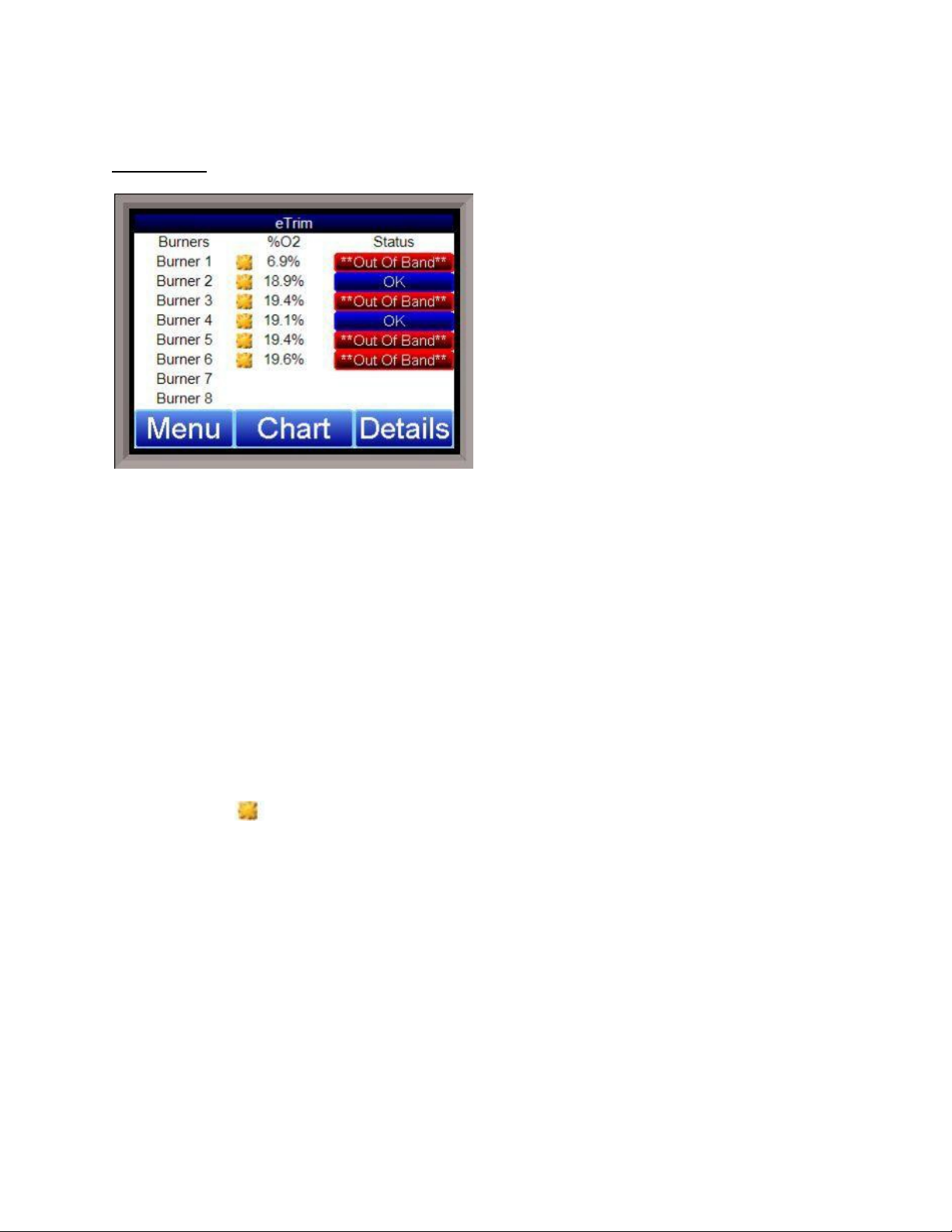
This is the main screen for the e-TRIM Touchscreen software. Once the software has booted up,
this screen will be displayed. This screen will list the Burners, along with the % Oxygen
reading, the Status of each burner, and the status of high fire or low fire. The possible
messages are:
•
– everything (coms, burner conditions, etc.) is ok.
•
•
- there is bad communication to the sensor board.
– there is an out of band condition, and the system is waiting for the
delay timer to expire.
•
- The burner is out of band. Status Disabled – The board has been
disabled.
•
•
- There is a critical alarm active.
– The critical alarm is active, but the alarm has been acknowledged.
The yellow icon signals that the burner is on high fire.
Super Systems Inc. Page 5 of 27 e-TRIM Operations Manual
Page 6
Details
NOTE:
Toggle
Close
time environment.
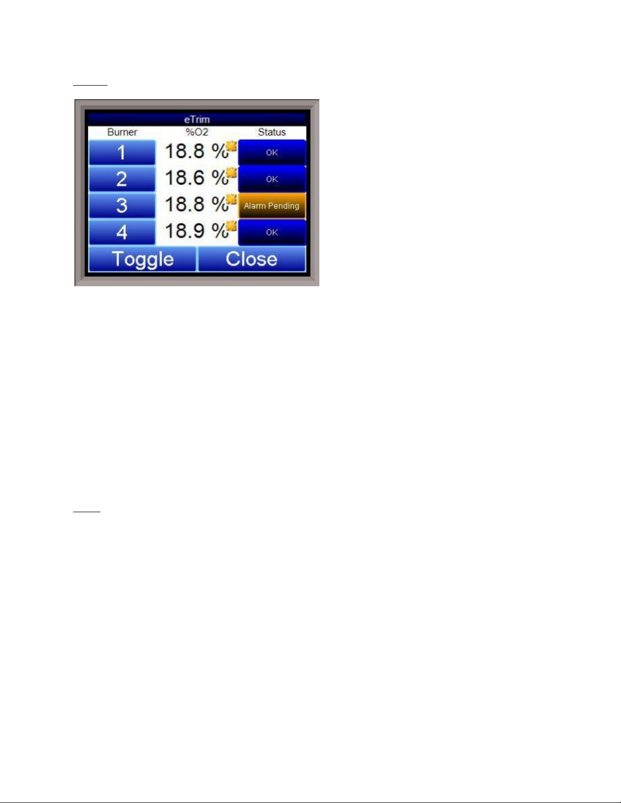
This will display a details screen for the e-TRIM system.
The
on the screen at one time, and each burner will have its oxygen reading and status displayed on
the screen. Clicking on the
Clicking on the
Clicking on the burner number will display some details about the specific burner: The board
address, baud rate, board version, TC type, TC temperature, Cold Junction temperature,
diagnostic, and percent oxygen.
Menu
This will display the menu, which will allow the user to configure the e-TRIM system. See the
section e-TRIM Menu for instructions on using the menu.
This manual was written with oxygen readings from the ambient air, not in a valid run-
Details
screen is basically an expanded version of the main screen. Four burners are shown
button will close the
button will display the next four burners, etc.
Details
screen.
Super Systems Inc. Page 6 of 27 e-TRIM Operations Manual
Page 7
e-TRIM Menu
NOTE:
Toggle
Set
time environment.
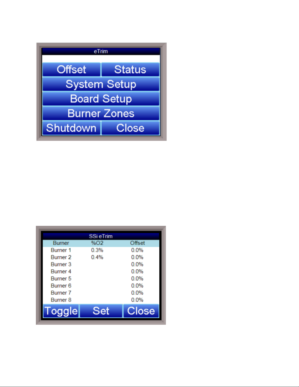
This screen is the main menu for the e- TRIM system. Currently, there are seven options:
This manual was written with oxygen readings from the ambient air, not in a valid run-
• Offset
• Status
• System Setup
• Board Setup
• Burner Zones
• Shutdown
• Close
Offset
The offset screen displays the %O2 and Offset percentage for eight burners at a time. Pressing
the
press the
Super Systems Inc. Page 7 of 27 e-TRIM Operations Manual
button will show the other eight burners. To change the offset of one of the burners,
button and select the burner number.
Page 8
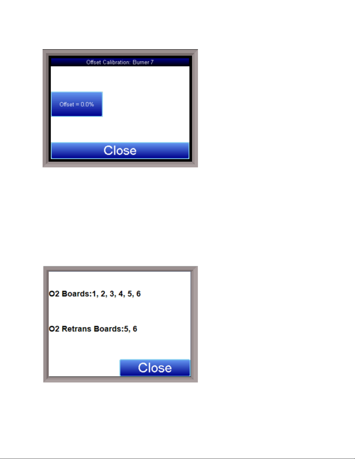
This screen will display:
Offset=
-20.9%
20.9%
Click the
This option will allow the user to enter an offset for each specific burner to match an external
calibration source such as a hand held oxygen monitor. Adjustments should only be made when
on high fire for more than 120 seconds.
To change an offset for a specific burner, select the burner from the drop-down list. The button
below the list will show the current offset. Click on this button to change the offset. The range
is
to
button to enter the offset percentage. Click OK to save it.
.
Status
Status
The
the controller.
Super Systems Inc. Page 8 of 27 e-TRIM Operations Manual
screen shows the addresses of the connected boards that are communicating with
Page 9
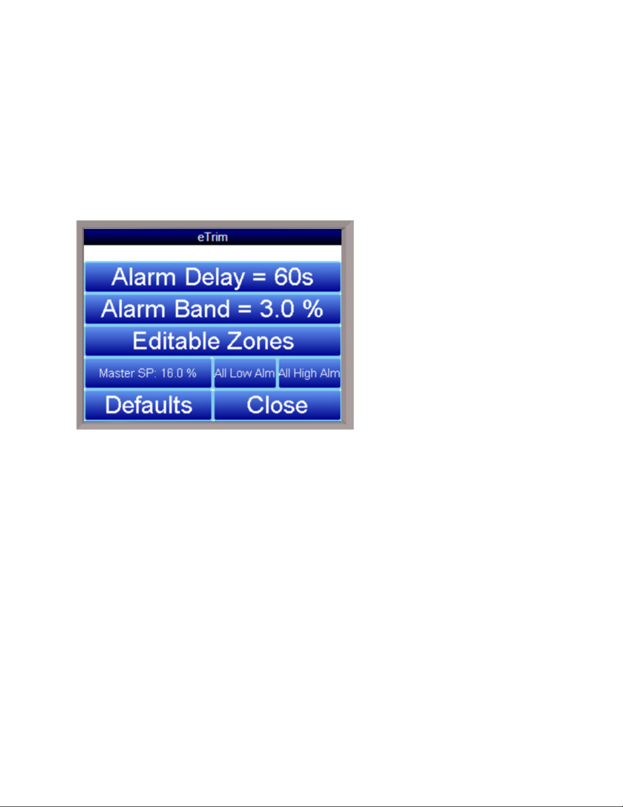
The O
0 to
60,000 seconds (0 minutes to 1,000 minutes)
NOTE:
Master High Fire, Individual High Fire,
Editable
Zones
Boards are the active circuit boards that are obtaining the oxygen measurement from
2
each sensor.
The O
Retransmission Boards (optional) are the circuit boards that provide an analog output (4-
2
20mA) of the oxygen measurement from each sensor. The electrical connections should be
made in accordance with the electrical schematic located at the back of this manual, with 4 to
20mA corresponding proportionally to 0 to 25% oxygen. The ability to retransmit the oxygen
signal requires circuit boards that are not part of the standard system. For additional
information regarding this feature, please contact Super Systems Inc. (513-772-0060).
System Setup
This option will allow the user to make changes to the current system settings. Currently, there
are six options to modify.
Alarm Delay
This setting is the number of seconds that the system will wait before showing an out of band
alarm condition, if an alarm condition is present. This is entered in seconds. The range is
.
Alarm Band
This setting is the band for the boards’ setpoint. If the setpoint is 3%, and the band is 2%, then
an alarm indication condition will not be present until the reading goes under 1% or above 5%.
This is entered in percentages. The range is 0% to 20.9%.
The alarm band will not
sound the horn and is for indication only. Output 7 can be wired to an external horn or light if
needed (see the electrical prints for termination details).
Master High Fire/Individual High Fire/Editable Zones
Clicking on this button will toggle between
. The Master High Fire setting will allow the controller to see the one digital input signal
and
as a high fire signal for all burners. Individual high fire will put the burners in groups of 4, each
group being a separate zone. Editable Zones will allow the user to determine the burner and
zone configuration. The high fire digital input is required for the e-TRIM system to provide band
Super Systems Inc. Page 9 of 27 e-TRIM Operations Manual
Page 10

alarm and critical alarm information. The default setting is master high fire. The master high
0%
20.9%
IMPORTANT:
Low Alarm
High Alarm
Active anytime, not just during high fire
Only active during high fire
A 0 (zero) setpoint blocks the alarm; alarm
disable does not block the alarm
Alarm disable blocks the alarm
fire contact is terminal 1270 to terminal 1340, as shown in the electrical drawing in “Appendix C
– Electrical Drawings (For Reference ONLY)”. See the electrical prints for more termination
details.
Master SP: 3.0%
This setting will control the master setpoint for the burners. This setting will set the desired
setpoint for all of the burners at once. This is entered in percentages. The range is
. A setpoint of 0% will disable the master setpoint and allow the individual burners to use
their setpoints.
All Low Alarms (All Low Alm)
This allows the controller to edit the low alarms for all 16 burners at once. They can be
changed individually through the Board Setup option. See IMPORTANT note below.
All High Alarms (All High Alm)
This allows the controller to edit the high alarms for all 16 burners at once. They can be
changed individually through the Board Setup option. See IMPORTANT note below.
Note the following about Low Alarm and High Alarm characteristics:
to
Note that the default critical high alarm value is 8%. The default critical low alarm value is 0%
(disabled).
Defaults
This will return all of the settings to the factory default settings. The user will have to confirm
this action before the defaults are set.
Close
This will close the
System Startup
screen.
Board Setup
This option will allow the user to make changes to each of the boards and their setup
parameters.
Super Systems Inc. Page 10 of 27 e-TRIM Operations Manual
Page 11

Board 1 – Board 16
0%
20.9%
0
10,000 seconds
Burner Active
Burner Inactive
The user will have to select the board to modify from the “Select Burner” list that appears after
Board Setup is selected (see screen shot above). The options are
.
Once the burner is selected, the screen above appears, allowing the user to change
configuration on that board.
Setpoint
This will modify the individual setpoint for control (not currently available). This setting is the
desired amount of oxygen for the burners. This is entered in percentages. The range is
.
to
Trim Delay
This setting will affect how long the system waits before activating any alarms, if necessary, or
the control trim. Since it takes a few seconds for the burner combustion gasses to reach the
sensor, the trim delay holds off any action until the sensor is truly seeing the gasses. This is
entered in seconds. The range is
.
to
Burner Active/Burner Inactive
This setting will modify whether the selected burner is active or inactive. Clicking on this option
will toggle between
and
.
Super Systems Inc. Page 11 of 27 e-TRIM Operations Manual
Page 12

Alarm Enabled
Alarm Disabled
0
100
0
100
Edit
Alarm Enabled
This setting will modify whether the selected burner’s Band alarm is active or inactive. An
inactive alarm will not sound if an alarm condition is present. Clicking on this option will toggle
between
Low Alm
This will modify the low alarm setpoint. This alarm will sound when the amount of oxygen is
lower than the value indicated when the high fire input is wired to the external high fire contact.
The low alarm will sound when there is a low amount of oxygen being read, which could mean
that too much fuel is being consumed or there is an extremely rich environment. This is entered
in percentages. The range is
High Alm
This will modify the critical alarm setpoint. This alarm will sound when the amount of oxygen
exceeds the value when the high fire input is wired to the external high fire contact. The critical
alarm will sound when there is a high amount of oxygen being read, which could mean that a
burner is not lit, or there is an extremely lean environment. This is entered in percentages. The
range is
to
.
and
to
.
.
Close
This will close down the
Board Setup
menu.
Burner Zones
This option will allow the user to view all the burners and their corresponding zones. To change
the zones, press the
button, and choose the proper burner number. Enter the new zone
Super Systems Inc. Page 12 of 27 e-TRIM Operations Manual
Page 13

and press OK. Note that Editable Zones must be configured in the System Setup menu in order
to edit the burner and zone settings.
Edit
This option will allow the user to select the burner and set the zone.
Close
This will close down the Burner Zones menu.
Shutdown
This option will show the e-TRIM Touchscreen software down and display the Windows CE©
desktop. This option is useful if the user needs to make any changes to the Touchscreen itself,
or if the user is removing the memory card from the Touchscreen for data transfer.
Close
This option will close the menu screen and return the user to the main screen.
Super Systems Inc. Page 13 of 27 e-TRIM Operations Manual
Page 14

NOTE:
Chart
time environment.
This will display a chart of the data points for the e-TRIM system. Currently, the data points that
are logged are the Oxygen readings for up to sixteen burners. Each oxygen reading will be a
separate line and color on the graph.
The red line on the graph will act as a cursor. Holding down the stylus on the red line and
moving to the left or the right will modify the time on the bottom of the chart and update the
oxygen values displayed.
The red “X” in the top right corner will close the
The date for display can be changed by clicking on the down arrow next to the date in the top left
corner.
The beginning time for the display range will be listed in the bottom left corner of the chart. The
middle of the display range will be listed in the center of the chart. The chart will always use
the current system time as the starting point for the display range. If the range is 8 Hours, then
the time in the left corner of the chart will be 8 hours ago, and the time in the middle of the
chart will be 4 hours ago. If the range is 12 Hours, then the time in the left corner of the chart
will be 12 hours ago, and the time in the middle of the chart will be 6 hours ago.
If the user holds the stylus or their finger down on the white area of the chart for three (3)
seconds, a sub chart menu will be displayed.
This manual was written with oxygen readings from the ambient air, not in a valid run-
Chart
screen.
Super Systems Inc. Page 14 of 27 e-TRIM Operations Manual
Page 15

fx
Cancel
The button on the left - - is the Trend Lines button. This button will allow the user to
select which trend lines (data points) to display on the chart, as well as view statistics for each
data point. Note – Removing a trend line from display does not stop logging the data for that
point. If the checkbox is checked, that data point will be displayed on the chart. If the checkbox
is unchecked, the data point will not be
displayed. Clicking on the check box will
toggle between checked and unchecked.
The “
” button will display the statistics for
the selected data point. The statistics that
are displayed are: the name of the data
point, the minimum value for the date/time
range, the maximum value for the
date/time range, the number of data points
in the date/time range, the average value
for the date/time range, and the standard
deviation for the date/time range.
The OK button will save any changes made and close down the Trend Lines screen. The
button will simply close down the Trend Lines screen and not save any changes that have been
made.
- is the datagrid button. This will
display all of the data points for the trend
lines in a column format. The date/time
range for the display will be the same as
the date/time range for the chart.
- is the undo button. This will
undo any zooming on the chart and return it to the original aspect.
Super Systems Inc. Page 15 of 27 e-TRIM Operations Manual
Page 16

- will move the chart display back in the past by half of the display range. For example, if
the display range is 12 Hours, then clicking on this button will display six more previous hours.
- will allow the user to change the display time range for the chart. The options are:
1 hour
2 hours
4 hours
8 hours
12 hours
24 hours
- will move the chart display forward in the future (up to the current time) by half of the
display range. For example, if the display range is 12 Hours, then clicking on this button will
display the next six hours.
- will put the chart into real-time mode. When in realtime mode, the chart cursor (red
line) will move to the far right of the chart and display those values. Once a minute, these values
will be updated as the time refreshes.
Super Systems Inc. Page 16 of 27 e-TRIM Operations Manual
Page 17

Chart Sub Menu
Zoom,
Restore, Add Note, Data,
Exit
Zoom
Restore
Add Note
Add Note
Data
Exit
There is a sub-menu available by putting a finger or a stylus anywhere on the chart and holding
it there for a couple of seconds. The sub-menu will have the following options available:
and
.
The
option will allow the user
to zoom in on a particular part of
the screen. Once this has been
selected, the user can take a stylus
or a finger and create a box around
the desired data. Once the user
releases the stylus or finger, a
zoom is no longer possible, and the
user will need to re-select the
option from the sub-menu to zoom
in again.
The
option will back out of any zoom
options that have been performed and display
the chart screen as it initially was.
The
option allows the operator to
enter a note on the chart, similar to writing on
a paper chart. The note shows up when the
chart is printed out using the utility software
included with the SERIES 9130
instrumentation. Pressing the
option
displays a screen where the operator can
enter the operator ID or initials and a note.
The user has the option to enter a note using the operator interface keyboard, where he or she
will be able to type in the note; or the user can use the Signature mode, which will allow them to
write a note using a stylus.
The
option will show the trend data as a data grid instead of the trend lines on a chart. This
functionality is exactly the same as if the user pressed the Datagrid View button - - from
the chart screen.
will close out the sub-menu without selecting an item.
Super Systems Inc. Page 17 of 27 e-TRIM Operations Manual
Page 18

Warranty
Limited Warranty for Super Systems Products:
The Limited Warranty applies to new Super Systems Inc. (SSI) products purchased direct from
SSI or from an authorized SSI dealer by the original purchaser for normal use. SSI warrants
that a covered product is free from defects in materials and workmanship, with the exceptions
stated below.
The limited warranty does not cover damage resulting from commercial use, misuse, accident,
modification or alteration to hardware or software, tampering, unsuitable physical or operating
environment beyond product specifications, improper maintenance, or failure caused by a
product for which SSI is not responsible. There is no warranty of uninterrupted or error-free
operation. There is no warranty for loss of data—you must regularly back up the data stored on
your product to a separate storage product. There is no warranty for product with removed or
altered identification labels. SSI DOES NOT PROVIDE ANY OTHER WARRANTIES OF ANY KIND,
INCLUDING, BUT NOT LIMITED TO, THE IMPLIED WARRANTIES OR CONDITIONS OF
MERCHANTABILITY AND FITNESS FOR A PARTICULAR PURPOSE. SOME JURISDICTIONS DO
NOT ALLOW THE LIMITATION OF IMPLIED WARRANTIES, SO THIS LIMITATION MAY NOT APPLY
TO YOU. SSI is not responsible for returning to you product which is not covered by this limited
warranty.
If you are having trouble with a product, before seeking limited warranty service, first follow the
troubleshooting procedures that SSI or your authorized SSI dealer provides.
SSI will replace the PRODUCT with a functionally equivalent replacement product,
transportation prepaid after PRODUCT has been returned to SSI for testing and evaluation. SSI
may replace your product with a product that was previously used, repaired and tested to meet
SSI specifications. You receive title to the replaced product at delivery to carrier at SSI shipping
point. You are responsible for importation of the replaced product, if applicable. SSI will not
return the original product to you; therefore, you are responsible for moving data to another
media before returning to SSI, if applicable. Data Recovery is not covered under this warranty
and is not part of the warranty returns process. SSI warrants that the replaced products are
covered for the remainder of the original product warranty or 90 days, whichever is greater.
Super Systems Inc. Page 18 of 27 e-TRIM Operations Manual
Page 19

Appendix A – e-TRIM Modbus Registers
11
Active burner bitmap
15
Master Setpoint (2 decimal places)
16
Deviation alarm band setpoint (2 decimal places)
17
Out of band alarm delay time
18
Alarm disable bitmap
19
Alarm bitmap, burners 1 - 16.
20 - 35
O2 readings, sensors 1 - 16, 2 decimal places.
68 - 83
High Fire ON, sensors 1 - 16.
116 - 131
O2 trim delay, sensors 1 - 16.
132 - 147
O2 trim interval time, sensors 1 - 16.
148 - 163
O2 alarm state, sensors 1 - 16.
0 = normal, 1 = bad communications, 2 = out of and pending, 3 = out
164 - 179
Alarm delay timer (sec), sensors 1 = 16.
180 - 195
O2 offset, sensors 1 - 16.
220 - 235
Slave communications status, boards 1 - 16. 0 = bad
communications, 4 = OK.
460
Critical alarm bitmap
477 - 492
Critical alarm set point, sensors 1 - 16.
493
Critical alarm acknowledge. 1 = acknowledged.
600
High fire total time (sec), sensor 1
601
High fire total time (hr), sensor 1
602
Low fire total time (sec), sensor 1
603
Low fire total time (hr), sensor 1
604
High fire timer, sensor 1
605
Low fire timer sensor 1
606 - 611
Timers for Sensor 2
612 - 617
Timers for sensor 3
618 - 623
Timers for sensor 4
624 - 629
Timers for sensor 5
630 - 635
Timers for sensor 6
636 - 641
Timers for sensor 7
The following list is a description of the relevant Modbus registers in the e-TRIM system. For
communications, the e-TRIM supports Modbus on the Host 485 port and ModbusTCP through
Ethernet.
14 Modbus address
of band.
461 - 476 Critical alarm, sensors 1 - 16.
642 - 647 Timers for sensor 8
Super Systems Inc. Page 19 of 27 e-TRIM Operations Manual
Page 20

648 - 653
Timers for sensor 9
654 - 659 Timers for sensor 10
660 - 665
Timers for sensor 11
666 - 671
Timers for sensor 12
678 - 683
Timers for sensor 14
690 - 695
Timers for sensor 16
672 - 677 Timers for sensor 13
684 - 689 Timers for sensor 15
Super Systems Inc. Page 20 of 27 e-TRIM Operations Manual
Page 21

Appendix B – Spare Parts List
31296
3.5" Touch Screen
13562
e-TRIM Controller
13584
e-TRIM Sensor Cable
31430
Oxygen Sensor
31594
Oxygen Sensor Control Circuit Board
31621
4-20 mA Output Board
The following is a list of spare parts, with SSi part numbers, for the e-TRIM system.
Super Systems Inc. Page 21 of 27 e-TRIM Operations Manual
Page 22

Appendix C – Electrical Drawings (For Reference ONLY)
Super Systems Inc. Page 22 of 27 e-TRIM Operations Manual
Page 23

Super Systems Inc. Page 23 of 27 e-TRIM Operations Manual
Page 24

Appendix D – Typical Installations Based on Application
The following pictures show typical installations based on common e-TRIM applications. Your
installation requirements may vary; the pictures in this section provide examples only and
should not be used as instructional pictures.
Typical Setup of e-TRIM with BIQ Furnace
Typical BIQ Furnace Installation
Close-Up of BIQ Sensor Installation with Top Exhaust
Super Systems Inc. Page 24 of 27 e-TRIM Operations Manual
Page 25

Typical Setup of e-TRIM with Continuous Furnace
Typical Continuous Furnace Installation
Close-Up of Continuous Furnace Sensor Installation
Super Systems Inc. Page 25 of 27 e-TRIM Operations Manual
Page 26

Example Setup of e-TRIM in a Custom Installation
Example Custom Installation
Super Systems Inc. Page 26 of 27 e-TRIM Operations Manual
Page 27

Revision History
Rev.
Description
Date
MCO #
-
Initial Release
6/11/2010
N/A
A
Changed the “alarm delay” to “trim delay” in the
registers (Appendix A)
6/23/2010
2076
B
Updated Screen Shots & descriptions, added new
info
10/31/11
2086
C
Updated specification to include the Quad board
Changed screen shots as needed
1/18/2013
2108
D
Added warning related to exposure of electronics
warranty information.
05/20/2015
2162
overview section; Changed the “Trim Delay”
description; Changed the “Alarm Enabled”
description; Modified some of the Modbus
photo, added electrical drawings, added high fire
for the 4-20mA retransmission and/or control
Updated the wiring diagram to identify which
digital input is for the master high fire
Updated manual text to cover new screen options
enclosure to high temperatures, as well as
electronic enclosure mounting. Added default
values for critical low alarm and critical high
alarm. Added example installation pictures for
typical applications. Updated parts list. Added
Super Systems Inc. Page 27 of 27 e-TRIM Operations Manual
 Loading...