

Page 1
eFLO
ELECTRONIC GAS
FLOW METER
OPERATIONS MANUAL
Super Systems Inc.
www.supersystems.com
7205 Edington Drive
Cincinnati, OH 45249
513-772-0060
Fax: 513-772-9466
Page 2

eFlo Electronic Flow Meter Operations Manual
Super Systems Inc.
Page 2 of 25
Super Systems Inc.
Super Systems Europe
Super Systems Mexico
Super Systems China
USA Office
Corporate Headquarters
7205 Edington Drive
Cincinnati, OH 45249
Phone: (513) 772-0060
http://www.supersystems.com
Sistemas Superiores Integrales S de RL de CV
Querétaro, QRO CP, MEXICO 76120
Phone: +52 (442) 410 9040
http://www.supersystems.com
Units 3 & 4, 17 Reddicap Trading Estate,
Sutton Coldfield, West Midlands
B75 7BU
UNITED KINGDOM
Phone: +44 (0) 121 329 2627
http://www.supersystemseurope.com
No. 335 XianXia Road
Room 308
Shanghai, CHINA
200336
Phone: +86 21 5206 5701/2
http://www.supersystems.com
Page 3

eFlo Electronic Flow Meter Operations Manual
Super Systems Inc.
Page 3 of 25
Table of Contents
Introduction ..................................................................................................................................... 4
Safety Information ....................................................................................................................... 4
Specifications .................................................................................................................................. 4
Replacement Parts ......................................................................................................................... 5
Installation Procedure .................................................................................................................... 6
Mechanical Installation ............................................................................................................... 6
Electrical Connections ................................................................................................................ 7
Modbus Registers ........................................................................................................................... 8
Operating Procedure....................................................................................................................... 9
Valve Control Mode ....................................................................................................................11
Setpoint Control and Adjustment ...............................................................................................11
Flow Limit Control (Automatic Mode) ........................................................................................12
Flow Alarm .................................................................................................................................13
Flow Rate Totalizer ....................................................................................................................14
Setup ..........................................................................................................................................14
Maintenance ...................................................................................................................................14
Zero Calibration .............................................................................................................................15
Flow Rate Calibration ....................................................................................................................15
Configuration and Control Software: FlowMeterView ...................................................................17
Prerequisites and Installation ....................................................................................................17
Operation ....................................................................................................................................17
Device Menu ...............................................................................................................................18
Curves Menu...............................................................................................................................19
Update Menu ..............................................................................................................................20
About Menu ................................................................................................................................20
Troubleshooting .............................................................................................................................21
Warranty.........................................................................................................................................23
Revision History .............................................................................................................................24
Appendix 1: Electrical/Wiring Diagram .........................................................................................25
Page 4
eFlo Electronic Flow Meter Operations Manual
Super Systems Inc.
Page 4 of 25
Introduction
eFlo
FlowMeterView
WARNING!
manual. Exceeding specified values could result in hazardous conditions.
Specifications
Power Required
24 VDC @ 400 mA
Accuracy
4%
Repeatability
2%
Turndown Ratio
6:1
Medium Temperature Limits
-10°F to 150°F (-20°C to 65°C)
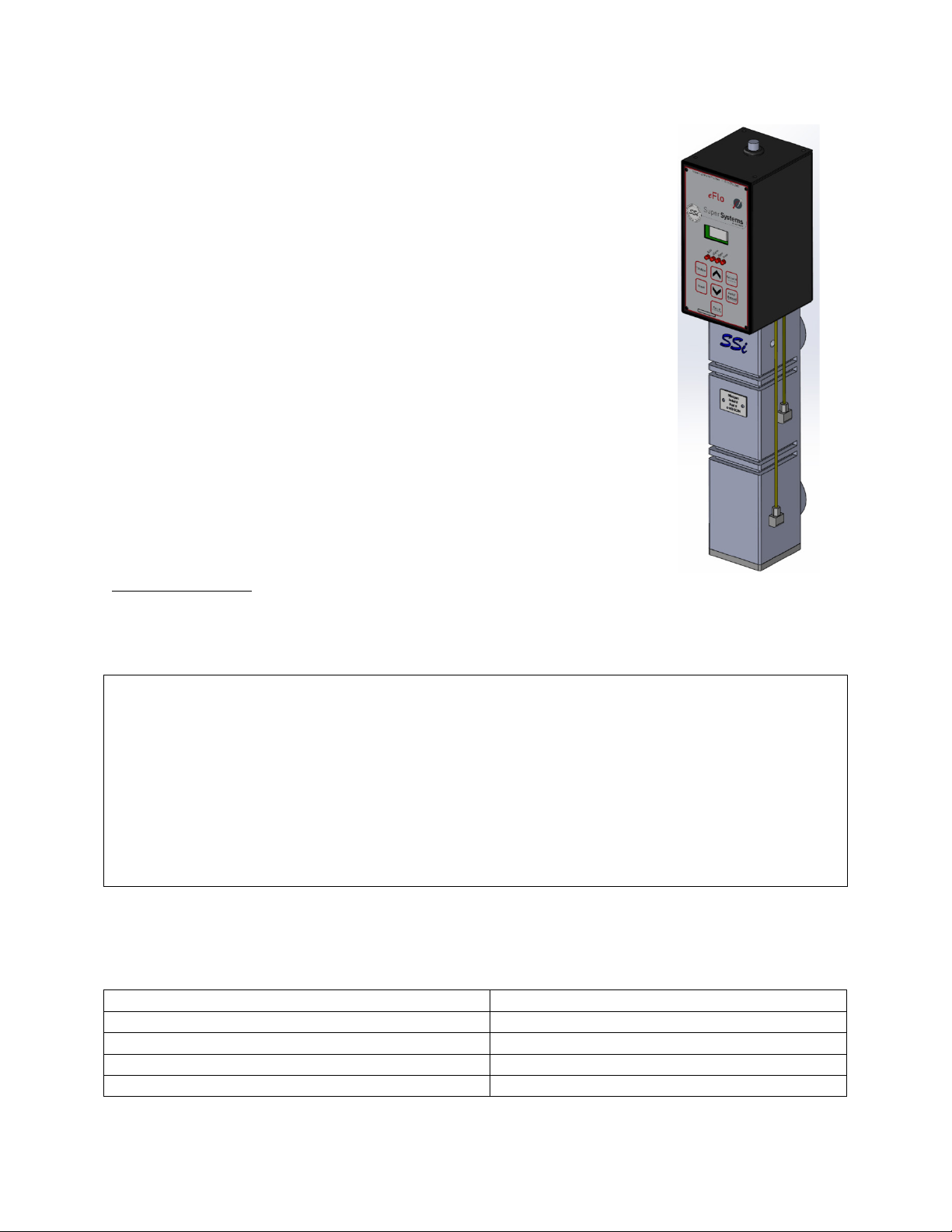
Figure 1 - eFlo 3-
dimensional angled
view
The
instrument is Super Systems Inc.’s electronic flow meter. eFlo
works by measuring the differential pressure (the difference in pressure
of a gas at two points) of a gas flowing through a specially designed
opening in the gas flow assembly. Based on properties of the flowed gas,
the differential pressure can then be used to calculate the flow rate of
the gas.
The eFlo features built-in high and low flow rate alarms and a flow rate
totalizer. The gas flow valve can be operated in manual mode or
automatic mode. Automatic mode allows the eFlo to use a flow rate
setpoint as a basis for adjusting the valve (and thus the gas flow) using a
built-in valve motor. The setpoint can be programmed manually by the
user or obtained by the instrument from a 4-20mA analog signal or
digital signal over RS485.
eFlo is part of SSi’s Flow Meter lineup, which also includes the FLO-
®
SCOPE
manual flow meter.
This manual also covers the configuration and control software provided
with the eFlo meter: SSi
.
Safety Information
Observe the following safety requirements when configuring, operating,
servicing, or maintaining the eFlo instrumentation.
The eFlo instrument is NOT guaranteed to provide gas shutoff, nor is it designed to do so. For
reliable gas shutoff, incorporate a valve that provides positive gas shutoff. Ensure that all gas
flow equipment is in compliance with National Fire Protection Agency (NFPA) requirements,
including those found in NFPA 86. Failure to follow these requirements could result in
flammable gas leaks into the unit.
Ensure that the air and gas mixture ratio settings are within the specifications provided in this
The specifications for the eFlo instrument are as follows.
Page 5

eFlo Electronic Flow Meter Operations Manual
Super Systems Inc.
Page 5 of 25
Ambient Temperature Limits
-10°F to 150°F (-20°C to 65°C)
Flow Output Signal (Linear)
4-20mA
Maximum Output Signal Load
500Ω
Input Control Signal (Linear)
4-20mA
Response Time
1 – 10 seconds
Communications
RS232, RS485
Communication Protocol
Modbus RTU
Pressure Drop @ 100% Capacity
drop.
5” wcg (Standard Model)
Flow Meter Pressure Limits
Report for more details.
5 psig – maximum allowable
Table 1 - eFlo Specifications
Replacement Parts
Part Number
Item
Explanation
33149
Motor and Shaft
Drives the Valve Needle open and
flow.
34224
O-Ring, eFlo Body & Plate
O-ring that seals the three
Bottom Plate, and Motor Plate.
37315
O-Ring, eFlo Valve Needle Shaft
O-ring that seals the Valve
Plate.
37321
Gasket, eFlo Motor Plate
Gasket that seals the eFlo Motor
and Motor.
34603
Grommet, Cylinder Adjustment
Grommet on top of the Electronic
Housing.
34692
Calibration Test Ports
Two pressure ports located on
meter.
10” wcg (Standard Model)
See Calibration Report for specific pressure
The pressure will be calibrated to userspecified requirements. See the Calibration
Replacement parts can be ordered for the eFlo unit when and if needed. Contact SSi at (513)
772-0060 to order parts.
closed to maintain the correct gas
components of the eFlo Body
(upper, lower, and middle),
Needle Shaft against the Motor
Plate to the Motor Spacer Block
the side of the Body of the meter.
These ports allow the pressure
drop to be measured for
calibration verification of the
Page 6

eFlo Electronic Flow Meter Operations Manual
Super Systems Inc.
Page 6 of 25
Part Number
Item
Explanation
31182
Pressure Transducer
Measures the pressure drop
flow.
31542
Flow Board
The primary electronics board
input and output pins.
31657
Motor Control Board
The electronics board that
motor.
20823
Cable
6 foot pigtail for RS485, 4-20mA
if desired.
Table 2 - Replacement Parts List
Installation Procedure
through the Element and provides
that signal to the electronic
boards for calculation of the gas
containing all of the circuitry and
controls the operation of the
input, 4-20mA output and 24VDC
power. Note that use of the cable
is not mandatory: connections
can be made directly to terminals
Installing the eFlo unit consists of a mechanical installation and an electrical installation. The
mechanical installation includes mounting as well as inlet and outlet piping. The eFlo unit will
be assembled prior to shipment. Before beginning installation:
• Ensure that all fittings and connections are tightly secured prior to beginning
installation.
• Ensure that all expected components are present. Contact SSi at (513) 772-0060 if you
have questions.
Mechanical Installation
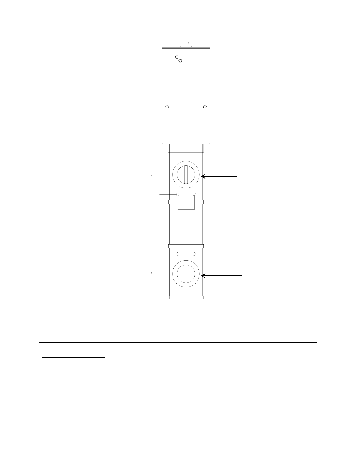
Secure mounting is achieved by correctly and securely installing the required piping in the inlet
and outlet connections of the eFlo unit. Note the distance between the centers of inlet and
outlet openings is 8.3” (21.1cm). The outlet openings themselves measure 1.25” NPT. The
locations of these connections are shown in Figure 2. Use of bushings or reducers at these
connections is okay as long as the maximum flow rate can still be achieved. Contact SSi at (513)
772-0060 for questions about pipe sizing.
Page 7
eFlo Electronic Flow Meter Operations Manual
Super Systems Inc.
Page 7 of 25
Figure 2 - Flow Outlet and Inlet Connections
IMPORTANT!
board can be found in Appendix 1: Electrical/Wiring Diagram.)
8.30
5.00
1.40
Outlet Connection
Inlet Connection
(Opening: 1.25” NPT)
Ensure that the inlet pressure is within specified parameters for your eFlo unit.
Electrical Connections
The eFlo unit uses a male 9-pin D-Sub connector for electrical connections. The electrical
connections are defined in Table 3
(Opening: 1.25” NPT)
below. (An electrical/wiring diagram for the flow control
Page 8

eFlo Electronic Flow Meter Operations Manual
Super Systems Inc.
Page 8 of 25
9-Pin D-Sub Pin
Number
Wire-In Color
Signal Type
Description
1
Red
+ VDC
Power Supply 24 VDC (250 mA)
2
Black
- VDC
3
Green
+ mA
Output Flow Signal (4 – 20 mA)
4
White
- mA
5
Orange
+ mA
Input Setpoint Signal (4 – 20 mA)
6
Blue
- mA
7
Brown
+ RS485
Communications Signal provided by
8
Yellow
- RS485
9
Purple
24V Sinking
Flow Alarm Output
NOTE: The alarm current should have a
maximum current rating of 100mA. An
back diode should
be used if the output is driving an
inductive load (such as a contactor or
horn).
Table 3 - Electrical Connections
NOTE:
Modbus Registers
Modbus Register
Number
Description
16
Actual Flow
17
Flow Sensor mA Input Value
18
Flow Setpoint
19
Decimal Place for Display of Flow and Setpoint
20
Instrument Modbus Address
21
Flow Meter Full Scale Value
22
Control Gain
23
mA Zero Value
24
mA Span Value
25
Deadband for Control
26
Setpoint Zero
27
Setpoint Span
28
Not Used
29
Analog Output Zero in Flow Units
30
Analog Output Span in Flow Units
31
Not Used
32
Low Flow Alarm Setpoint
33
High Flow Alarm Setpoint
34
Alarms
Modbus over serial.
Output
If RS-232 is needed, an additional 9-pin D-Sub connector can be set up on the eFlo unit
prior to shipment.
The eFlo Modbus registers are as follows.
isolation relay with fly-
Page 9

eFlo Electronic Flow Meter Operations Manual
Super Systems Inc.
Page 9 of 25
Modbus Register
Number
Description
35
Auto (1) / Manual (0) for Control
36
(Not Used)
37
Reset Totalizer Values to Zero
38
(Not Used)
39
Totalizer Units (0 to 9999)
40
Totalizer in 10,000s (0 to 9999 -> 0 to 99,990,000)
41
Totalizer in 10,000,000s (0 to 9999 -> 0 to 999,900,000,000)
Table 4 - Modbus Registers and Descriptions
Operating Procedure
IMPORTANT!
The eFlo system is equipped with a flow rate alarm (high and low), flow rate totalizer, and
integrated valve control. The unit can be operated in either manual or automatic mode for flow
rate control. This section of the manual provides an explanation of how the unit is operated:
valve control modes, flow limit control, flow alarming, flow totalizing, and programming of the
unit.
For best long term results, it is recommended that pressure be maintained on the flow meter at
all times. Pressure can be maintained when the shut off solenoid/valve is downstream from the
outlet of the meter. This will ensure long term calibration and accuracy.
Figure 3 shows the layout of the flow control panel on the eFlo unit. An explanation of the
panel’s components is provided as well. The panel layout will be referenced further in this
section.
Page 10

eFlo Electronic Flow Meter Operations Manual
Super Systems Inc.
Page 10 of 25
Figure 3 - eFlo Flow Control Panel Layout
A – LED display
B – Status indicators
C – Totalizer button
D – Up button
E – Setpoint button
F – Reset button
By default, the LED display is used to display the
current flow. With different button combinations,
the LED display can also be used to show the
totalizer value, current setpoint, and Setup menu
options with associated settings. Alarm status
messages may also be displayed.
These are four lights that come on in various
situations.
Auto – When lit, the eFlo is in Auto valve control
mode. When not lit, the unit is in Manual valve
control mode.
Alarm – When lit, an alarm is active. This will be
a Low Flow Rate Alarm, a High Flow Rate Alarm,
or a Limit Switch Alarm.
Open – When lit, the valve is driving open.
Drive – When lit, the valve is driving. If this light is
illuminated, but the Open light is not, the valve is
driving closed.
When pressed and held, the Up button will increase the flow rate through the inlet connection
by opening the valve. This button can also be used in conjunction with other items, such as
Setpoint and Setup menu options.
When pressed and held, this button will show the current flow setpoint. By default, the setpoint
can be changed manually by pressing the up or down arrow to increase or decrease the setpoint
while the Setpoint button is being held. It is important to note that the setpoint cannot be
manually changed when the eFlo unit is obtaining a remote setpoint from another instrument.
The remote setpoint can be obtained using an analog or digital signal; it will overwrite any
manual input from the user. See the Setpoint Control and Adjustment on page 11 for more
details.
When pressed and held for five seconds, the Reset button will erase the current totalized flow
value and change it to zero.
When pressed and held, the totalized flow value
is shown. After being held for a few seconds, the
value will begin to scroll to the left to show the
full totalized numeric value.
Page 11

eFlo Electronic Flow Meter Operations Manual
Super Systems Inc.
Page 11 of 25
G – Down button
H – Auto/Manual button
I – Setup button
When pressed and held, the Down button will decrease the flow rate through the inlet
connection by closing the valve. This button can also be used in conjunction with other items,
such as Setpoint and Setup menu options.
This button toggles the Valve Control Mode between Auto and Manual. To change the current
mode, hold the button in for five seconds.
In Auto Valve Control Mode, the eFlo unit will automatically change the position of the valve. It
will drive the valve open or closed depending on the flow needed at any given time (for example,
in order to maintain setpoint).
In Manual Valve Control Mode, the position of the valve is determined by the operator using the
Up and Down arrows.
The Setup button will open the Setup menu when the button is held for five seconds. The options
are displayed on the LED screen. Scroll through the options by pressing the Setup button.
Change the values by pressing the Up and Down buttons. Change the values by pressing the Up
and Down buttons.
Refer to the Setup section below for more information.
Valve Control Mode
The Valve Control Mode can be either Auto or Manual. In Auto mode, the motorized valve will be
automatically adjusted. If the currently measured flow rate is lower than setpoint, the valve will
be driven open. If the currently measured flow rate is higher than setpoint, the valve will be
driven closed.
To change Valve Control Mode, hold the Auto / Manual button down for five seconds. The Auto
light will show which control mode is active. If the Auto light is illuminated, Auto mode is active.
If the light is not illuminated, Manual mode is active.
Setpoint Control and Adjustment
The setpoint can be controlled and adjusted using one of four methods:
1. Manually, by using the Setpoint button
2. By using a remote analog signal (4-20mA)
3. By using a remote digital signal with Modbus serial communications over RS485
4. By using the FlowMeterView software (refer to the Device Menu on page 18).
It is important to note that the remote setpoint setting overwrites any manual setting.
Therefore, if manual control of setpoint is desired, ensure that there is no external signal
overwriting the manual setting.
Page 12

eFlo Electronic Flow Meter Operations Manual
Super Systems Inc.
Page 12 of 25
IMPORTANT!
Flow Limit Control (Automatic Mode)
Adjusting the flow limit setting can result in erratic operation if the adjustment is performed
improperly. For this reason, it is recommended that the adjustment be performed by an SSi
technician or with technical support. For more information, contact SSi at (513) 772-0060.
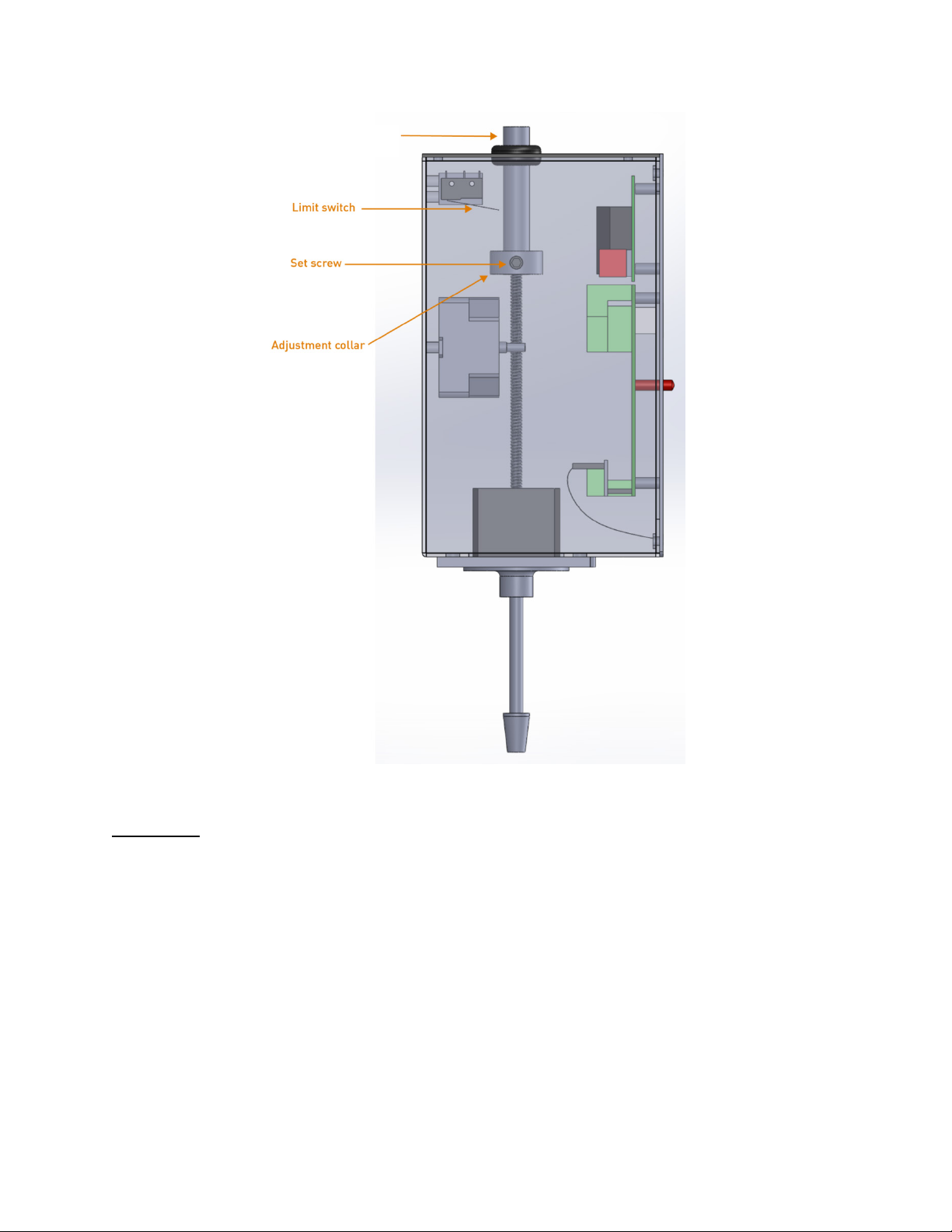
In Automatic Valve Control Mode, a mechanism is needed to prevent the control valve from
opening too far (if the value opens too far, damage to the motor could result). A limit switch on
the eFlo unit provides this mechanism (see Figure 4). This adjustment was completed during
calibration of the eFlo instrument. In the event that the adjustment collar was moved from its
factory set position, the steps below describe how to reset this collar to the proper position. To
set the limit switch to a proper setting for your application:
1. In the Automatic Valve Control Mode, set the eFlo control valve to allow for full flow
capacity as specified when the instrument was purchased. Allow the valve to reach the
maximum flow so that the motor stops moving.
2. Using a 1/8” hex wrench, loosen the adjustment collar and move it so that it is located
approximately 1/8” below the limit switch.
3. Tighten the set screw on the adjustment color to lock its position on the adjustment
cylinder.
4. Set the eFlo instrument to zero flow so that the adjustment lowers and the valve closes.
5. Again, set the eFlo instrument to full flow capacity. Observe the adjustment collar’s
location relative to the limit switch.
6. Verify that the adjustment collar has traveled to the same location (approximately 1/8”
from the limit switch), indicating the correct position of the collar.
7. Ensure that the set screw is tightened properly.
The limit switch should now be properly set.
Page 13
eFlo Electronic Flow Meter Operations Manual
Super Systems Inc.
Page 13 of 25
Figure 4 - Location of Manual Adjustment Cylinder, Set Screw, and Adjustment Collar
Adjustment cylinder
Flow Alarm
The eFlo meter incorporates a High Flow Alarm and Low Flow Alarm. Setpoints for these
alarms are set through a Modbus interface or by using SSi’s FlowMeterView software (provided
free of charge to eFlo users).
When the alarm is active, the Alarm light will turn on. A warning message will be displayed on
the LED screen.
In order to function properly, the flow alarm setpoints must be set prior to use of the eFlo unit,
and the alarm must be wired properly. The alarm current should have a maximum current
rating of 100mA. An isolation relay with fly-back diode should be used if the output is driving an
inductive load (such as a contactor or horn). See Appendix 1: Electrical/Wiring Diagram for
more information on wiring.
Page 14

eFlo Electronic Flow Meter Operations Manual
Super Systems Inc.
Page 14 of 25
GAIN:
DEAD
ADDR
ZERO
BAUD:
Maintenance
Do not apply pressure to the pressure transducer.
Flow Rate Totalizer
The eFlo meter’s flow rate totalizer records cumulative flow rates measured by the meter. The
totalizer is active at all times. The maximum totalized value is 999,999,999,999 (the unit of
measurement is any unit of flow measurement). To show the totalized value, press and hold the
Totalizer button. The totalized value will begin scrolling across the LED screen if the value is
greater than what the screen can display.
To reset the totalizer to zero, press and hold the Reset button for five seconds.
Setup
The Setup button will open the Setup menu when the button is held for five seconds. The options
are displayed on the LED screen. Scroll through the options by pressing the Auto/Manual
button. Change the values by pressing the Up and Down buttons.
The available options are as follows.
Gain is used to control the speed of valve response for automatic control. The higher the
value, the more quickly the valve will open and close. The lower the value, the more slowly it
opens and closes. The range for this value is 10 to 500.
(Deadband): Deadband is used to determine the area above and below the setpoint where
no control action will occur. If the deadband is too small, the control may oscillate around
setpoint. If the deadband is too high, the flow will not reach setpoint. The range for this value is
1 to the full scale flow value.
(Address): The Address is the RS485 Modbus address of the eFlo unit. The range for this
value is 1 to 249.
: The Zero value is the adjusted mA input from the pressure transducer. This value allows
the user to adjust the pressure transducer, which transmits a 4-20mA signal to indicate flow.
When no flow is present, the ideal value for the Zero value is 4.00mA (although the value will not
always be exactly 4.00). To change the Zero value, use the Up and Down buttons. To reset the
Zero value and remove any previous adjustments, press the Up and Down buttons
simultaneously. For more information, refer to the
The Baud is the serial baud rate. This value can be 9600 or 19200 (1920 represents
Zero Calibration section on page 15.
19200).
SSi recommends the following maintenance guidelines for the eFlo meter.
Clean any carbon or water from pressure transducer gas lines as needed. To do this:
1. Remove the rubber tubing from one side of the pressure transducer located in the
electronics enclosure. (Note that the two tubes plumbed to the pressure transducer
must not be switched; otherwise, the meter will not read properly.) The other end of the
tubing should be connected to the stainless steel tubing plumbed vertically along the
right side of the meter.
2. Apply air to the tubing to “flush” out any carbon and/or moisture, which may have
developed.
3. Reassemble the tubing to the pressure transducer port and repeat the procedure for the
other side of the pressure transducer.
Page 15

eFlo Electronic Flow Meter Operations Manual
Super Systems Inc.
Page 15 of 25
Zero Calibration
zero drift.
zero value
.
zero calibration
zero offset
Setup
Auto/Manual
first mA value
Down
first mA value
first mA value.
Down
Flow Rate Calibration
IMPORTANT!
have any questions, please contact SSi at (513) 772-0060.
4. Verify gas flow with manometer.
When the flow rate is set to zero, it is possible that drift can occur due to a pressure difference
on the inlet as compared to the factory calibration pressure setting This is called
One
way to avoid zero drift is to position the shutoff valve or isolation solenoid downstream of the
flow meter so that gas flows through the shutoff or isolation solenoid after entering the eFlo
inlet. This is the preferred shutoff/isolation method.
In the eFlo meter, there is an adjusted mA input based on the pressure transducer
measurement when the flow rate is zero. This mA value is known as the
zero value will be 4.00mA
present, a
the
to account for the pressure applied to the inlet at zero gas flow. The procedure is
In a situation where pressure is applied to the inlet but no flow is
in the field will often be required. Zero calibration involves changing
; ideally, the
as follows:
1. Press and hold the
2. Press the
button until the LED screen displays Configuration mode.
button to cycle through options until “ZERO” flashes on the
screen.
3. Note the
4. Using the Up and
value below the
NOTE: To remove any previous adjustments, press the Up and
shown on the factory Calibration Report.
buttons, change the displayed value to the
or a
buttons at the same
time.
The zero offset is now adjusted.
The following procedure is used for calibration of flow rate for the purpose of eFlo certification.
To ensure consistency and quality, it is recommended that this procedure be performed by SSi
personnel. SSi takes no responsibility for calibrations performed by non-SSi personnel. If you
For this procedure, you will need a calibrated manometer, a small standard screwdriver, and
the original Calibration Report for the eFlo unit.
1. On the left side of the unit (when facing it), you will notice two barb fittings. One is a high
pressure port and a low pressure port used for calibration. The high pressure port is the
lower port; the low pressure port is located above the high pressure port.
2. Using a small standard screwdriver, turn the small valve located in each pressure port
counterclockwise one full turn.
3. Connect a calibrated manometer to the test ports. Remember that the high pressure
port is the lower port; the low pressure port is located above the high pressure port.
4. Set the actual flow rate to a value tested on the original Calibration Report.
Page 16

eFlo Electronic Flow Meter Operations Manual
Super Systems Inc.
Page 16 of 25
NOTE:
5. Using the manometer, measure the actual differential pressure at the selected flow
rate. Compare the differential pressure to the differential pressure shown on the
Calibration Report.
6. If the actual differential pressure is within acceptable limits (±4% of the full scale value),
no action is necessary. If the actual differential pressure is not within acceptable limits,
adjust the zero/span potentiometers inside the differential pressure transducer. The
pressure transducer is located inside the black enclosure on top of the unit.
Typically, a 0.5”wc deviation equates to 5% flow error.
Page 17

eFlo Electronic Flow Meter Operations Manual
Super Systems Inc.
Page 17 of 25
Configuration and Control Software: FlowMeterView
IMPORTANT!
Before running FlowMeterView, ensure that the eFlo unit is connected to the computer using an
Device, Curves, Updates,
About.
Device;
Curves
Update
About
Status
Selected Port,
SSi’s FlowMeterView software is used to configure and control the eFlo meter via a serial
connection (RS232 or RS485). This software is provided free of charge to eFlo customers. If you
have an eFlo meter and need to obtain FlowMeterView, please contact SSi at (513) 772-0060.
Prerequisites and Installation
To run properly, FlowMeterView must be run on a computer with Windows XP or higher.
Windows 7 or higher is recommended. The computer on which FlowMeterView is running must
have a working serial port (either RS232 or RS485) for communication with the eFlo meter.
Finally, the eFlo meter must be configured for the serial communications standard that is being
used: RS232 or RS485.
To use FlowMeterView with the eFlo unit, you first need to install the software. To do this, run
the file
shipped with the eFlo unit. When you run the program, you will be prompted with a series of
steps. Administrator access may be required for proper installation of the program. Contact
your IT system administrator with system-related questions or SSi at (513) 772-0060 if you have
questions about the installation procedure.
Operation
setup.exe
. This is an installation and setup program and is usually supplied on a CD
RS232 or RS485 connection. Take note of the COM port number that the eFlo unit is connected
to on the computer.
To run the software, open FlowMeterView from the Windows Start menu. The shortcut for
FlowMeterView is typically found in the SuperSystems program group.
Once the software is running, you will see a window similar to the one pictured in Figure 5
FlowMeterView interface is designed to be straightforward. On the left-hand side of the window,
you will see menu options:
double-click on it. The default menu is
and values on the eFlo meter. The
save curves to the local computer, download the active curve from the meter, and upload a
curve to the meter. The
software updates and, if available, give you the option to download and install any updates. The
menu shows version information for the software as well as a change log.
At the top of the FlowMeterView window, you will see a connection
down menu,
menu, when selected, will cause the software to check for
that allows you to select the COM port for communication with the
menu allows you to adjust Calibration Curve points,
and
this menu is used to view and change settings
To select a menu option,
as well as a drop-
. The
Page 18
eFlo Electronic Flow Meter Operations Manual
Super Systems Inc.
Page 18 of 25
The correct COM port must be selected in order for the software to be able to
communicate with the meter
Device
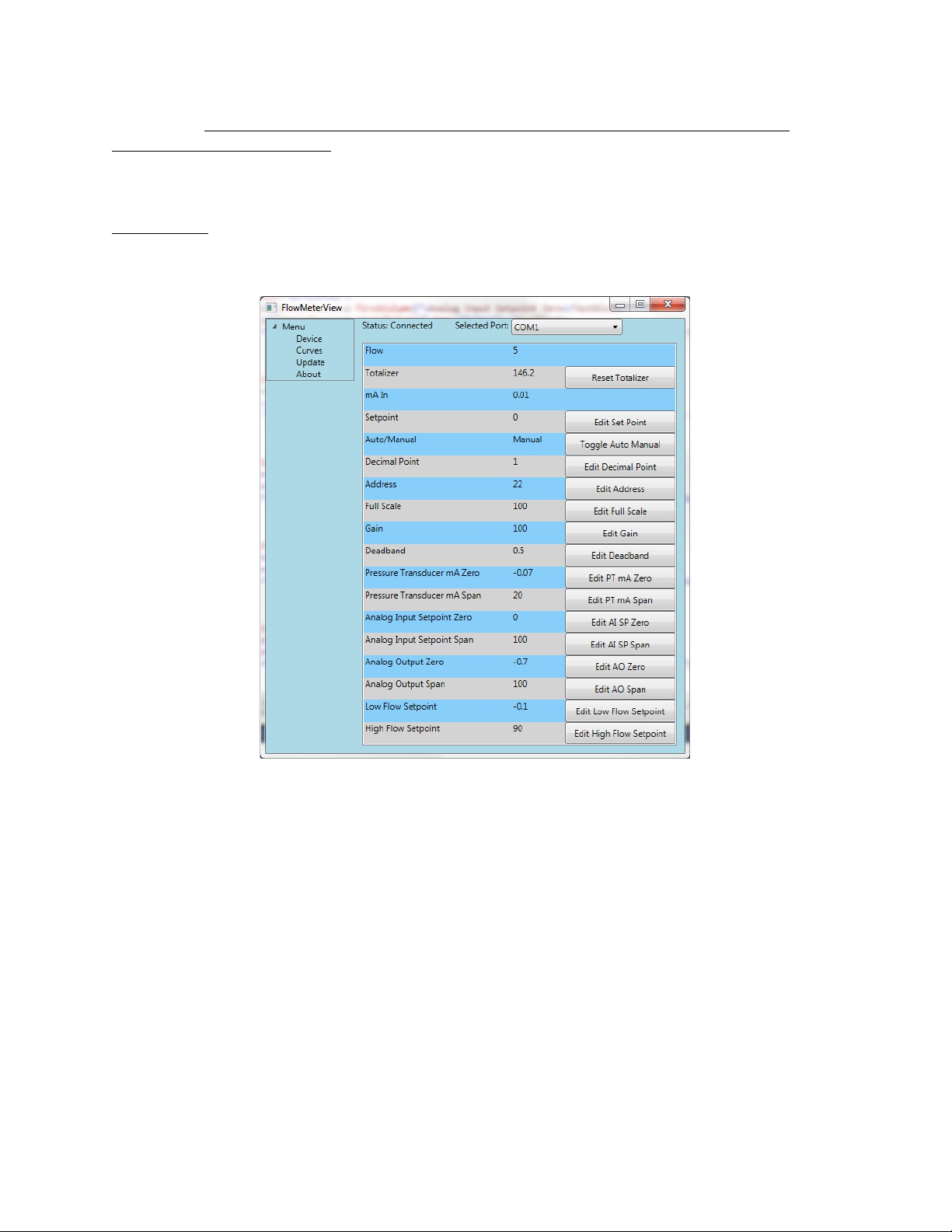
Figure 5 - FlowMeterView Device Menu
Flow.
Totalizer.
Reset Totalizer
mA In.
Setpoint.
Edit Set Point
Auto/Manual.
Toggle Auto
Manual
Decimal Point.
Edit Decimal
Point
Address.
Edit Address
Full Scale.
Edit Full Scale
eFlo meter.
The menus are described in more detail in the following sections.
Device Menu
Using the
.
menu, you can view and change settings and values on the eFlo meter.
The settings and values that can be accessed in this menu are as follows:
•
The current flow rate read from the eFlo unit.
•
•
•
value.
•
•
•
that value.
•
you to change this value.
The current totalized flow.
The current milliamp value of the analog input signal.
The current flow setpoint.
The current setting for valve control mode: Auto or Manual.
changes the mode between Auto and Manual.
The number of decimal places used in the flow display.
allows you to change this value.
The RS485 Modbus address of the eFlo unit.
The maximum flow value to be measured by the meter.
resets the value to zero.
allows you to change the setpoint
allows you to change
allows
Page 19

eFlo Electronic Flow Meter Operations Manual
Super Systems Inc.
Page 19 of 25
Gain.
Edit Gain
Deadband.
Edit Deadband
Pressure Transducer mA Zero.
Edit PT mA Zero
NOTE:
Pressure Transducer mA Span.
Edit PT mA Span
Analog Input Setpoint Zero.
Edit AI SP Zero
Analog Input Setpoint Span.
Edit AI SP Span
Edit SP Zero
Analog Output Zero.
Edit AO Zero
Analog Output Span.
Edit AO Span
Low Flow Setpoint.
Edit Low Flow Setpoint
High Flow Setpoint.
Edit High Flow
Setpoint
Curves
•
The current gain. This value controls the speed of valve response for automatic
control. The higher the value, the more quickly the valve will open and close. The lower
the value, the more slowly it opens and closes.
•
action will occur. If the deadband is too small, the control may oscillate around setpoint.
If the deadband is too high, the flow will not reach setpoint. The range for this value is 1
to the full scale flow value.)
•
This value allows the user to adjust the pressure transducer, which transmits a 4-20mA
signal to indicate flow. When no flow is present, the ideal value for the Zero value is
4.00mA (although the value will not always be exactly 4.00).
to adjust the zero value.
to change the zero value—a procedure described in more detail in the
section on page 15.
•
transducer. For instance, if 20mA is the highest value that the transducer will send, the
mA span value is 20.
•
value will correspond to approximately 4mA.
value.
•
This value will correspond to approximately 20mA.
this value.
•
signal from the eFlo meter. This value will correspond to approximately 4mA. If the flow
range is 0 to 100, the Analog Output Zero value will be 0.
change this value.
•
signal from the eFlo meter. This value will correspond to approximately 20mA. If the
flow range is 0 to 100, the Analog Output Span value will be 100.
to change this value.
•
active as long as the flow rate is less than or equal to this value.
allows you to change this value.
•
active as long as the flow rate is greater than or equal to this value.
Curves Menu
The
local computer, download the active curve from the meter, and upload a curve to the meter.
menu (Figure 6) allows you to adjust Calibration Curve points, save curves to the
The value defining the area above and below the setpoint where no control
The adjusted mA input from the pressure transducer.
allows you to change this value.
allows you to change this value.
The lowest flow rate that will be transmitted by an analog output
The highest flow rate that will be transmitted by an analog output
The value that will trigger a Low Flow Rate Alarm. The alarm will be
The value that will trigger a High Flow Rate Alarm. The alarm will be
This achieves the same result as using the eFlo keypad
The highest value of the mA range sent by the pressure
allows you to change this value.
The lowest flow rate value for a remote setpoint of 0. This
The highest flow rate value for the remote setpoint flow.
allows you to change the deadband value.
allows you to change the value.
Zero Calibration
allows you to change this
allows you to change
allows you to
allows you
allows you
Page 20

eFlo Electronic Flow Meter Operations Manual
Super Systems Inc.
Page 20 of 25
Figure 6 - Curves Menu
Saved Curves
Selected Curve
Curve Points
Saved Curves
Selected Curve
Saved Curves
Curve Points
Update
Figure 7 – Update Menu
About
The window has three sections related to the Calibration Curve:
Figure 6),
(Section “B” in Figure 6), and
These sections are described in more detail below.
•
(“A”). This section of the window displays a list of saved Calibration
Curves. It also allows you to begin work on a new curve (by clicking on “New Curve”) and
to delete a selected curve (by clicking on “Delete Curve”). To select a curve, single-click
on the name of the curve.
•
(“B”). This section displays the name of the curve selected from the
area. It also provides the ability to save the current curve to a file on the
local computer (“Save Curve” button), upload the current curve to the eFlo unit (“Upload
Curve To Device”), and download the curve that is currently loaded in the eFlo unit
(“Download Curve From Device”).
•
(“C”). This section allows you to define new points on the currently selected
Calibration Curve and to delete existing points on that curve. Flow values correspond
with milliamp signal values produced by the eFlo unit; each point denotes where these
values coincide on the Calibration Curve. New points are defined with the “New Point”
button. Selected points are deleted with the “Delete Point” button.
Update Menu
The
menu (Figure 7) will cause the software to check for software updates and, if
available, give you the option to download and install any updates.
(Section “A” in
(Section “C” in Figure 6).
About Menu
When selected, the
(Application Version) and a change log (Revision Notes).
menu will bring up a window showing the software version
Page 21

Super Systems Inc.
Page 21 of 25
Troubleshooting
WARNING!
When troubleshooting, follow all proper safety precautions. Use proper eye protection and hand protection at all times.
Problem
Possible Causes
Possible Corrective Actions
Unit is not reaching higher flow setpoint
Pressure may be less than pressure specified on
Adjust regulator using a manometer to set
maximum flow required through the meter.
Unit is indicating that there is gas flow when no
Zero value is not set on the meter (if gas supply is
Verify that the hand valve for gas supply is closed.
on page 15 for more details.
eFlo Electronic Flow Meter Operations Manual
flow should be present
order
Meter may not be the correct size
Meter may not be calibrated for correct gas
Gas piping may be too small for required flow
shut off)
The shutoff valve may be located upstream of the
flow meter. This causes a zero drift condition
since there is no pressure on the meter.
correct pressure while gas is flowing and meter
is open
Call SSi at (513) 772-0060 to discuss a different
size (model) of flow meter
Verify Calibration Report for gas calibration. If the
gas is different than the gas you are flowing
through the meter, contact SSi at (513) 772-0060
to discuss a recalibration.
Verify that the plumbing is adequate for the
If flow is still showing, perform the zero
calibration procedure as shown in the manual.
• SSi recommends that the shutoff valve be
moved downstream of the meter so that gas
pressure on the meter is always available.
The error will correct itself when gas
pressure is supplied to the meter.
• Another option is to perform a Zero
Calibration. See the Zero Calibration
section
Page 22

eFlo Electronic Flow Meter Operations Manual
Super Systems Inc.
Page 22 of 25
Problem
Possible Causes
Possible Corrective Actions
Unit is indicating that there is no gas flow when
Hand valve for gas supply may be closed
gas supply
Open hand valve.
restriction, and correct any problems.
Unit is not communicating
Communications may not be configured correctly
Verify RS485 wire polarity
the RS485 loop
Unit is not reaching setpoint
There may be insufficient gain
Verify gain is high enough; adjust bias as needed
Setpoint cannot be changed directly from the
An analog setpoint signal may be wired and
overwriting manual setpoint
Ensure that an analog input signal to the eFlo is
setpoint via communications
Table 5 - Troubleshooting
calling for a flow setpoint
eFlo control panel
If a solenoid is used, solenoid may not be
energized
Restrictions may be present downstream in the
overwriting manual setpoint
A master device wired to the eFlo may be
Ensure that solenoid is energized.
Check for issues such as exhaust gas outlet
Verify address and baud rate
Verify that only one meter has address set to 1 on
not wired and overwriting manual setpoint
Ensure that no device is actively writing the
If you experience problems and cannot find the solution after troubleshooting, please call SSi Technical Support at (513) 772-0060.
Page 23

eFlo Electronic Flow Meter Operations Manual
Super Systems Inc.
Page 23 of 25
Warranty
Limited Warranty for Super Systems Products:
The Limited Warranty applies to new Super Systems Inc. (SSI) products purchased direct from
SSI or from an authorized SSI dealer by the original purchaser for normal use. SSI warrants
that a covered product is free from defects in materials and workmanship, with the exceptions
stated below.
The limited warranty does not cover damage resulting from commercial use, misuse, accident,
modification or alteration to hardware or software, tampering, unsuitable physical or operating
environment beyond product specifications, improper maintenance, or failure caused by a
product for which SSI is not responsible. There is no warranty of uninterrupted or error-free
operation. There is no warranty for loss of data—you must regularly back up the data stored on
your product to a separate storage product. There is no warranty for product with removed or
altered identification labels. SSI DOES NOT PROVIDE ANY OTHER WARRANTIES OF ANY KIND,
INCLUDING, BUT NOT LIMITED TO, THE IMPLIED WARRANTIES OR CONDITIONS OF
MERCHANTABILITY AND FITNESS FOR A PARTICULAR PURPOSE. SOME JURISDICTIONS DO
NOT ALLOW THE LIMITATION OF IMPLIED WARRANTIES, SO THIS LIMITATION MAY NOT APPLY
TO YOU. SSI is not responsible for returning to you product which is not covered by this limited
warranty.
If you are having trouble with a product, before seeking limited warranty service, first follow the
troubleshooting procedures that SSI or your authorized SSI dealer provides.
SSI will replace the PRODUCT with a functionally equivalent replacement product,
transportation prepaid after PRODUCT has been returned to SSI for testing and evaluation. SSI
may replace your product with a product that was previously used, repaired and tested to meet
SSI specifications. You receive title to the replaced product at delivery to carrier at SSI shipping
point. You are responsible for importation of the replaced product, if applicable. SSI will not
return the original product to you; therefore, you are responsible for moving data to another
media before returning to SSI, if applicable. Data Recovery is not covered under this warranty
and is not part of the warranty returns process. SSI warrants that the replaced products are
covered for the remainder of the original product warranty or 90 days, whichever is greater.
Page 24

eFlo Electronic Flow Meter Operations Manual
Super Systems Inc.
Page 24 of 25
Revision History
Rev.
Description
Date
MCO #
-
First release
3/23/2015
4621
Page 25
eFlo Electronic Flow Meter Operations Manual
Super Systems Inc.
Page 25 of 25
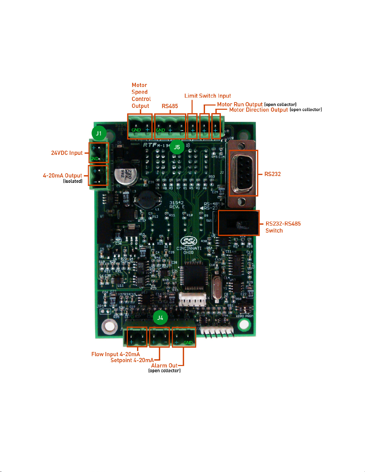
Appendix 1: Electrical/Wiring Diagram
Flow Board: Connection Diagram
 Loading...