

Page 1
SSi Super Systems Inc.
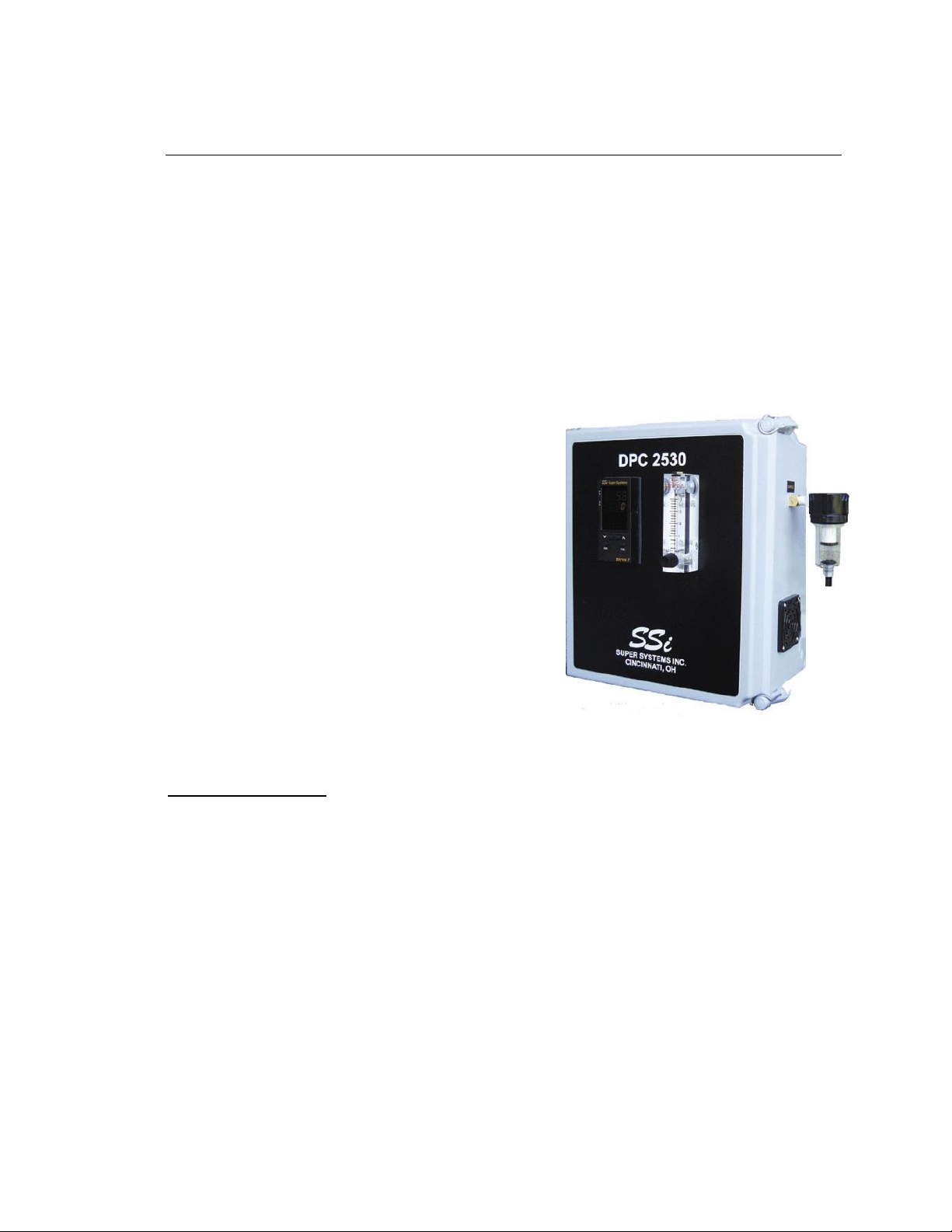
Product Manual #4553 - Model DPC2530 Continuous Dew Point Analyzer
Model DPC2530
Continuous Digital Dew Point Analyzer
For measurement of:
● Endothermic Atmosphere
● Exothermic Atmosphere
● Nitrogen / Hydrogen Atmosphere
● Plant Air Systems
SPECIFICATIONS –
Measurement Range: -50 to +80°F (-47 to +27°C)
Temperature Range: 0 to 120°F (-18 to +49°C)
Power Supply: 115 VAC 60Hz
Display Type: LED Digital
Display Resolution: +/- 1°F (+/- 0.1°C)
Digital Communications: RS485 Modbus
Control / Retransmission Output: 4 –20 mA
Alarms: Two Alarm Relays
Size: 11”H x 10”W x 7”D
Weight: Approximately 8 lb.
SSi Manual 4553 – DPC2530 Super Systems, Inc. Page # 1 of 17
Revision Level “E” (800) 666-4330
Page 2

SSi Super Systems Inc.
Product Manual #4553 - Model DPC2530 Continuous Dew Point Analyzer
TABLE OF CONTENTS –
SPECIFICATIONS – .................................................................................................................................. 1
TABLE OF CONTENTS – ......................................................................................................................... 2
INTRODUCTION –.................................................................................................................................... 2
WARNINGS – ............................................................................................................................................ 2
TERMINAL BLOCK WIRING – ............................................................................................................... 3
INSTRUMENT SETUP – ........................................................................................................................... 3
STARTUP – ................................................................................................................................................ 4
OPERATION - ............................................................................................................................................ 4
HOW IT WORKS – .................................................................................................................................... 5
FACTORY CALIBRATION – ................................................................................................................... 5
FIELD CALIBRATION – ........................................................................................................................... 5
RETURNING THE UNIT TO SSI – ......................................................................................................... 12
SPARE PARTS – ...................................................................................................................................... 12
APPENDIX “A” (DETERMINING THE DEW POINT IN °F)– ......................................................................... 13
APPENDIX “B” (DETERMINING THE DEW POINT IN °C) – ........................................................................ 14
APPENDIX “C” – (DETERMINING THE SENSOR TEMPERATURE IN °F) ...................................................... 15
APPENDIX “D” – (DETERMINING THE SENSOR TEMPERATURE IN °C) ...................................................... 16
REVISION HISTORY – ........................................................................................................................... 17
INTRODUCTION –
Thank you for selecting Super Systems Inc. and the DPC2530 as your source for accurate
dew point measurements.
We have taken every precaution to protect this unit during shipment. Carefully unpack
the instrument, and if there are any signs of shipping damage notify SSi and the shipper
immediately.
Keep this instruction book in a secure place and refer to it when there is a question about
the analyzer.
WARNINGS –
Although it is intended for use in an industrial environment, the DPC2530 is a sensitive
piece of analysis equipment. Care should be taken not to operate it in a manner
inconsistent with its intended use.
Moisture (water) cannot be allowed to enter the analyzer. If water is present in the
sample gas, use an in-line dryer for sample conditioning. In the event that the sensor
becomes wet, use an inert gas (Nitrogen or Argon) to dry the inside of the instrument.
Under no circumstances should Methane (Natural Gas) be used to dry the DPC2530.
SSi Manual 4553 – DPC2530 Super Systems, Inc. Page # 2 of 17
Revision Level “E” (800) 666-4330
Page 3
SSi Super Systems Inc.
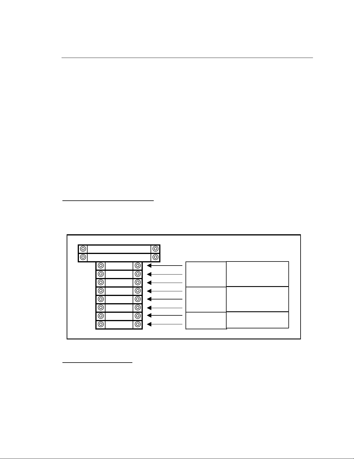
FU100 - 2.0 AMP
FU103 - 1.0 AMP
1000 Positive
1002 Negative
GND Ground
1101 Shield
1111 Positive
1121 Negative
1151 Positive
1161 Negative
120V 1 PHASE 60 HZ
SUPPLY POWER
4-20 mA
OUTPUT
RS 485 (MODBUS)
COMMUNICATIONS
Product Manual #4553 - Model DPC2530 Continuous Dew Point Analyzer
The analyzer must be stored at ambient temperature (65-80°F) for at least four hours
prior to operation.
An in-line dryer for sample conditioning should be used for exothermic and
combustion applications.
This unit is not designed to measure the dew points in corrosive gasses, such as
Ammonia, S03, Chlorine, and HCL.
Please read and understand this Product Manual before operating the unit.
Failure to comply with these conditions may cause damage to the unit that will not be
covered under the warranty. Super Systems, Inc. is not responsible for damage to this
unit caused by disregard of these warnings, neglect, or misuse.
TERMINAL BLOCK WIRING –
Power and communications wiring for the DPC2530 should be performed according to
the following diagram:
INSTRUMENT SETUP –
The instrument should be fully configured at the factory for immediate use. In the event
that the settings are ever lost, the following chart shows the appropriate input parameters
for the 7EK controller. When the instrument is set up in Fahrenheit using these
parameters, the input is scaled from –50 to +80°F and the 4-20mA output is scaled from –
SSi Manual 4553 – DPC2530 Super Systems, Inc. Page # 3 of 17
Revision Level “E” (800) 666-4330
Page 4

SSi Super Systems Inc.
7EK Input Parameters
Parameter
Fahrenheit
Celsius
P1
16
16
P2
No Decimal Place
One Decimal Place
P3
-50
-45.6
P4
600
315.5
P5
PU.rt
PU.rt
P6
4 – 20
4 – 20
P7
- 50
- 45.0
P8
80
25
Product Manual #4553 - Model DPC2530 Continuous Dew Point Analyzer
50 to +80°F. When the instrument is set up in Celsius using these parameters, the input is
scaled from –45.6 to +26.7°C and the 4-20mA output is scaled from –45 to +25°C.
In addition to these parameters, the jumpers located at position J1 inside the instrument
should be set with one jumper connecting pins 1 and 2, and the other jumper connecting
pins 5 and 6. Once again, these jumper settings will be set at the factory prior to
shipment.
STARTUP –
The DPC2530 Dew Point Analyzer has been calibrated before it was shipped from Super
Systems Inc. You can begin typical operation as soon as the unit has been allowed to
stabilize in a temperature similar to the temperature in the heat-treating department. This
is particularly important for units that may have been sitting overnight in a delivery van
in sub-zero weather, since the rapid temperature change can cause condensation on the
sensor which will cause the unit to temporarily display inaccurate readings.
OPERATION -
To obtain consistent accurate readings from the DPC2530, be sure that the element in the
bowl filter on the side of the instrument is clean and functional. Not only will this ensure
that the sample reading is not abnormally high (since soot tends to trap moisture), but it
will also prevent soot and other contaminants from entering the unit and damaging the
sensor. The optimum flow rate of the sample gas should be between 1.5 and 2.0 Standard
Cubic Feet per Hour (SCFH), although a flow rate as low as 1.0 SCFH is acceptable. If
the unit is reading less than 1.0 SCFH, verify that there are no obstructions to the flow
such as a clogged sample line or a poorly adjusted knob on the DPC2530’s flow meter.
Heat Treat Furnace Sampling: A gas sample may be extracted from a process using the
built-in pump. The sample tube from which the sample is taken out of the furnace should
SSi Manual 4553 – DPC2530 Super Systems, Inc. Page # 4 of 17
Revision Level “E” (800) 666-4330
Page 5

SSi Super Systems Inc.
Product Manual #4553 - Model DPC2530 Continuous Dew Point Analyzer
extend into the furnace past the HOT face of the refractory. For accurate results, a
designated sample port should be used to extract the sample. SSi offers a sample port
assembly (part number 20263) which is ideal for this purpose. If a designated sample
port is not available, then a clean “burn-off” port on a Gold Probe, an industry leading
oxygen sensor for atmosphere control, can be used.
Endothermic Generator Sampling: For applications under pressure, the pump should be
switched off and the flow controlled by the small restriction valve on the flow meter. A
flow rate between 1.5 and 2.0 SCFH is ideal. The sample should be taken from the
endothermic gas manifold after the gas has been cooled. NOTE: Allow the sample port
“to blow out any soot” before connecting the sample tube. Failure to do so will
unnecessarily coat the sample tubing assembly and possibly some internal components
with soot, resulting in inaccurate readings and exposing the sensor to potential damage.
HOW IT WORKS –
The dew point sensor is a “dielectric ceramic” that varies its electrical capacitance with
changes in relative humidity. The sensor is mounted in a short probe, which is installed
in a T-fitting that allows the sample gas to flow past the sensor. The tip of this probe
contains the dielectric ceramic relative humidity (RH) sensor, as well as a built in
temperature sensor to determine its dry bulb temperature. Information from both of these
sensors is used to compute the resultant dew point, which is displayed on the digital LED
display.
FACTORY CALIBRATION –
Factory calibration is recommended every six months if the unit is used regularly. SSi’s
calibration is NIST traceable and includes a numbered “Certificate of Calibration”. This
certificate also indicates the accuracy of the analyzer before and after calibration. Please
contact Super Systems at (800) 666-4330 for more information regarding this service.
FIELD CALIBRATION –
It is also possible to calibrate the DPC2530 in the field, which will require the optional
calibration kit (Part Number 31030). The instructions for a field calibration are shown
here, however please feel free to contact Super Systems at 800-666-4330 if you would
like to review the process with us before you begin.
The calibration kit consists of two bottles of saturated salt solution in which each bottle
generates a precise relative humidity percentage (R.H.%) value. One bottle is 11.3%
SSi Manual 4553 – DPC2530 Super Systems, Inc. Page # 5 of 17
Revision Level “E” (800) 666-4330
Page 6
SSi Super Systems Inc.
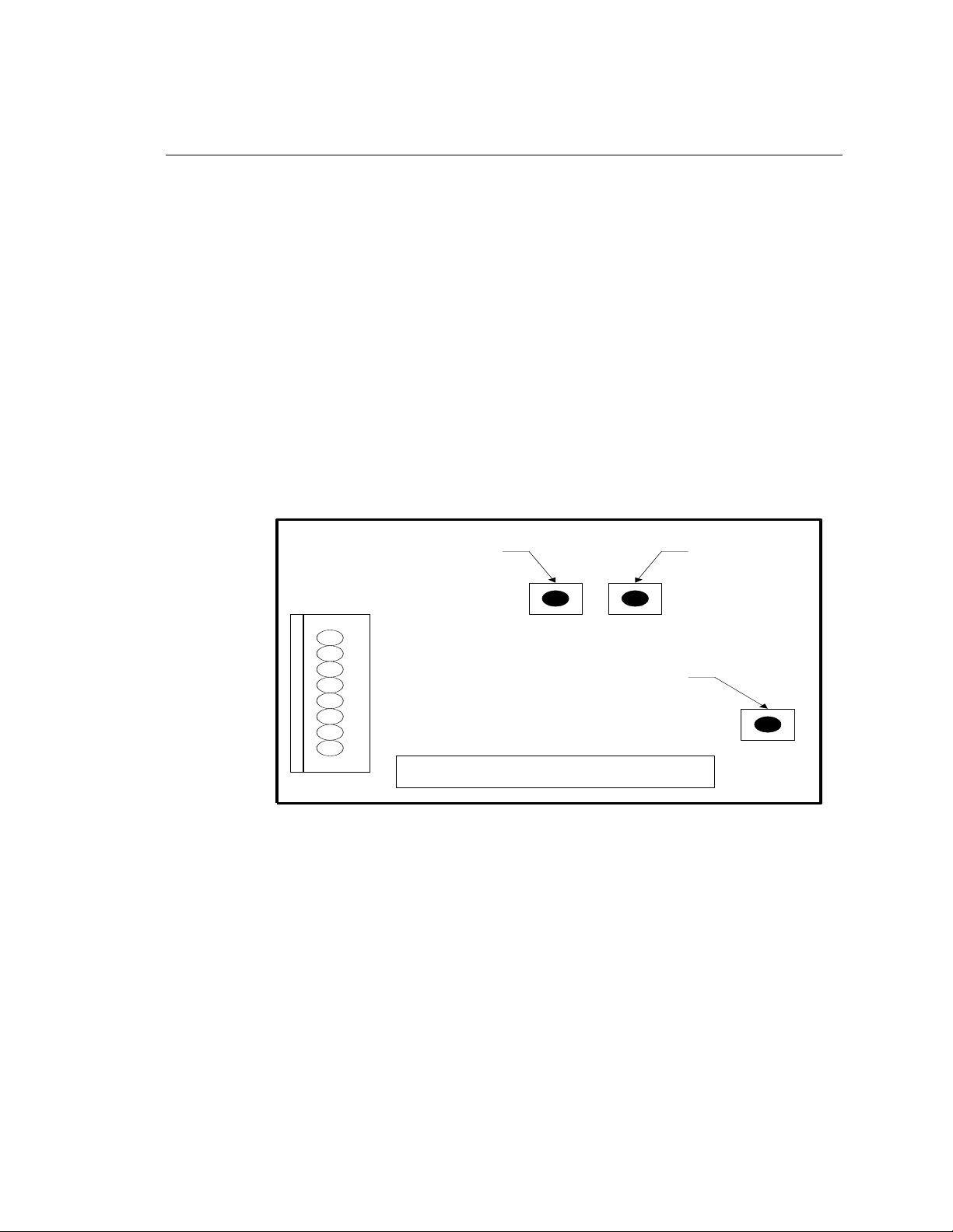
SPAN
BUTTON
(75.3)
ZERO
BUTTON
(11.3)
CAL
BUTTON
Dew Point Microprocessor Board
Product Manual #4553 - Model DPC2530 Continuous Dew Point Analyzer
R.H., and the other is 75.3% R.H. These two specific calibration points are already preprogrammed into the microprocessor board.
1.0 Open the unit.
1.1 Undo the latches on the side of the enclosure.
2.0 Locate the key components within the unit.
2.1 The microprocessor board is located in the front right side of the unit.
This board contains three very small buttons that are used for calibration.
Two are next to one another, and they are marked “75.3%” and “11.3%”,
while the other has no label. The unmarked button is the “Calibrate” button.
The approximate locations of each button are shown on this diagram:
2.2 The sensor-sampling chamber is located in the bottom left of the unit. It
is the gray rectangular box with brass barb fittings on either side and a black
plastic gland protruding from the center.
2.3 The sensor probe is positioned in the sensor sampling chamber. It is held
3.0 Remove the sensor probe from the sensor-sampling chamber.
in place by the nut on the black plastic gland.
3.1 Loosen the black plastic gland nut and slowly slide the sensor probe out
through the airtight seal. Care must be taken when removing this sensor probe,
since the tip is very delicate and can be easily damaged if it is mishandled.
SSi Manual 4553 – DPC2530 Super Systems, Inc. Page # 6 of 17
Revision Level “E” (800) 666-4330
Page 7

SSi Super Systems Inc.
Product Manual #4553 - Model DPC2530 Continuous Dew Point Analyzer
Note that the probe has white mark at the wire entry point, which must be
aligned with corresponding white mark in plastic gland when it is re-inserted
in the sampling chamber.
4.0 Install the sensor probe into the 75.3% salt solution.
4.1 Slip the black sensor gland (supplied in the calibration kit) over the sensor
probe with the sensor tip protruding from the threaded end of the gland and
the sensor wires being flush with the top of the rubber o-ring in the gland.
Tighten the gland around the sensor. This does not need to be done with a
wrench or other tools, but it does need to be tight enough to prevent ambient
air from contaminating the humidity level of the sampling chamber.
4.2 Remove the cap of the 75.3% salt solution and install the sensor gland
(with the sensor) into the salt solution. To increase the life of the calibration
salts, an effort should be made to minimize the amount of time that the salt
solution is exposed to the ambient air.
5.0 Allow the sensor to reach equilibrium with the calibration salt.
5.1 With the power to the unit still turned off, leave the sensor in the
calibration salt for a minimum of eighteen (18) hours. It is acceptable to leave
the sensor in the salt solution for a longer period of time, even a few days, if
desired.
6.0 Begin the 75.3% (Span) calibration process.
6.1 After leaving the sensor in the salt for at least eighteen (18) hours, turn the
unit on. The reading on the display is not important at this point.
6.2 Simultaneously press the “75.3%” and “Calibration” buttons on the
microprocessor board.
7.0 Verify the 75.3% (Span) calibration.
7.1 Do not be concerned if the unit does not display 75.3, since it is not
supposed to match the value of the calibration salt.
7.2 Use the “Sensor Temp” switch on the faceplate of the unit to determine and
record the sensor temperature.
SSi Manual 4553 – DPC2530 Super Systems, Inc. Page # 7 of 17
Revision Level “E” (800) 666-4330
Page 8

SSi Super Systems Inc.
Product Manual #4553 - Model DPC2530 Continuous Dew Point Analyzer
7.3 Look up this temperature on the “Theoretical Dew Point Values for
Calibration Verification” chart located in the back of this manual. Appendix
“A” will show the temperature values in Fahrenheit, and Appendix B will
show the temperature values in Celsius.
7.4 Next to the appropriate temperature, note the number in the corresponding
column titled “75.3%”. This should match with the dew point that is shown
on the display of the DPC2530.
8.0 Determine the acceptability of the reading.
8.1 The value printed on the chart in Appendix A is a theoretical value, and
some variation can be expected. When a calibration is performed at SSi, we
certify (in writing) that the unit displays within +/- 1 degree of the theoretical
value after it has been calibrated. We would not consider a calibration to be
successful unless it is within +/- 1 degree, however in the case of a field
calibration, this degree of accuracy may or may not be required. The degree
of accuracy that is acceptable is determined by the policy of the person
performing the calibration.
NOTE: Keep in mind that the DPC2530 only displays whole numbers, and
not tenths of a degree. Therefore, a reading of 65°F could be as low as 64.50
or as high as 65.49.
9.0 Allow the sensor to achieve equilibrium at ambient atmosphere.
9.1 After the 75.3% (Span) calibration has been completed, remove the sensor
from the calibration salt and replace the cap on the salt.
9.2 Leave the sensor probe in the gland and while the unit is still on, allow it to
achieve equilibrium at the ambient atmosphere in the room. This is
accomplished by simply leaving the sensor exposed to ambient air for
between two and three minutes. You will know when this has been
accomplished when the numbers on the display begin to stabilize.
10.0 Install the sensor probe into the 11.3% salt solution.
10.1 Remove the cap of the 11.3% salt solution and install the sensor gland
(with the sensor) into the salt solution. To increase the life of the calibration
salts, an effort should be made to minimize the amount of time that the salt
solution is exposed to the ambient air.
SSi Manual 4553 – DPC2530 Super Systems, Inc. Page # 8 of 17
Revision Level “E” (800) 666-4330
Page 9

SSi Super Systems Inc.
Product Manual #4553 - Model DPC2530 Continuous Dew Point Analyzer
10.2 Turn the unit off.
11.0 Allow the sensor to reach equilibrium with the calibration salt.
11.1 With the power to the unit still turned off, leave the sensor in the
calibration salt for a minimum of twenty-four (24) hours. It is acceptable to
leave the sensor in the salt solution for a longer period of time, even a few
days, if desired.
12.0 Begin the 11.3% (Zero) calibration process
12.1 After leaving the sensor in the salt for at least twenty-four (24) hours, turn
the unit on. The reading on the display is not important at this point.
12.2 Simultaneously press the “11.3%” and “Calibration” buttons on the
microprocessor board.
13.0 Verify the 11.3% (Zero) calibration
13.1 Do not be concerned if the unit does not display 11.3, since it is not
supposed to match the value of the calibration salt.
13.2 Use the “Sensor Temp” switch on the face plate of the unit to determine
and record the sensor temperature.
13.3 Look up this temperature on the “Theoretical Dew Point Values for
Calibration Verification” chart located in the back of this manual. Appendix
“A” will show the temperature values in Fahrenheit, and Appendix B will
show the temperature values in Celsius.
13.4 Next to the appropriate temperature, note the number in the corresponding
column titled “11.3%”. This should match with the dew point that is shown
on the display of the DPC2530.
14.0 Determine the acceptability of the reading.
14.1 The value printed on the chart in Appendix A is a theoretical value, and
some variation can be expected. When a calibration is performed at SSi, we
certify (in writing) that the unit displays within +/- 1 degree of the theoretical
value after it has been calibrated. We would not consider a calibration to be
SSi Manual 4553 – DPC2530 Super Systems, Inc. Page # 9 of 17
Revision Level “E” (800) 666-4330
Page 10

SSi Super Systems Inc.
Product Manual #4553 - Model DPC2530 Continuous Dew Point Analyzer
successful unless it is within +/- 1 degree, however in the case of a field
calibration, this degree of accuracy may or may not be required. The degree
of accuracy that is acceptable is determined by the policy of the person
performing the calibration.
NOTE: Keep in mind that the DPC2530 only displays whole numbers, and
not tenths of a degree. Therefore, a reading of 18°F could be as low as 17.50
or as high as 18.49.
15.0 Allow the sensor to achieve equilibrium at ambient atmosphere.
15.1 After the 11.3% (Zero) calibration has been completed, remove the sensor
from the calibration salt and replace the cap.
15.2 Leave the sensor probe in the gland and while the unit is still on, allow it
to achieve equilibrium at the ambient atmosphere in the room. This should
take between two and three minutes. You will know when this has been
accomplished when the numbers on the display begin to stabilize.
16.0 Re-assemble the unit.
16.1 After the calibration process has been completed, remove the sensor probe
from the gland and return it to the sensor-sampling chamber, taking care to
position it properly. The white mark on the sensor probe should face towards
the right of the sensor-sampling chamber (at 3:00 if it were the face of a
clock.). If the white mark is not visible, then it should be placed so the sample
flow directly strikes the face of the mirror on the sensor tip (the sample flows
from right-to-left). In other words, the mirror should face the incoming gas
stream.
16.2 Hand-tighten the black sensor gland to prevent air from leaking out of the
sampling chamber.
16.3 Verify that the system is leak proof by turning on the pump and placing a
finger over the sample inlet port. The flow meter will drop to zero if there are
no leaks. If a leak is detected, make sure that all tubing connections are tight,
especially the black sensor gland.
16.4 After the unit has passed the leak test, the enclosure door can be closed.
SSi Manual 4553 – DPC2530 Super Systems, Inc. Page # 10 of 17
Revision Level “E” (800) 666-4330
Page 11

SSi Super Systems Inc.
Product Manual #4553 - Model DPC2530 Continuous Dew Point Analyzer
17.0 Make sure that all caps are replaced on the calibration salts, and return the
DPC2530 to service.
SSi Manual 4553 – DPC2530 Super Systems, Inc. Page # 11 of 17
Revision Level “E” (800) 666-4330
Page 12

SSi Super Systems Inc.
Description
Part No.
Factory Calibration
13045
Sample Pump
31401
Filter
37048
Replacement filter element
31027
Flow meter
36027
7EK Display/Controller
31081
Dew Point Sensor
31038
Calibration Kit
31030
24VDC Power Supply
31125
Product Manual #4553 - Model DPC2530 Continuous Dew Point Analyzer
RETURNING THE UNIT TO SSi –
This analyzer contains some components that may require periodic replacement based on
the amount of use that the unit experiences and the methods in which it is used. If service
on the unit is necessary, it should be sent back to Super Systems, Inc. for repair. To
minimize damage to the mounting feet on the enclosure, it is possible to unscrew them
and rotate them 180 degrees (so they point into the enclosure instead of away from it).
This will reduce the likelihood that they will be damaged during shipment. If the original
packaging is not available, the analyzer should be surrounded by impact-absorbing
materials and placed in a box. It is the responsibility of the shipper to ensure that the
DPC2530 arrives at SSi undamaged.
Before shipping the analyzer, please call (800) 666-4330 to receive a Return Materials
Authorization (RMA) number. The shipping address that should be used for returns is:
Super Systems, Inc.
ATTN: RMA #XXXX
7205 Edington Drive
Cincinnati, OH 45249
SPARE PARTS –
To simplify the ordering of replacement parts, the following is a list of some of the
components that may be requested:
SSi Manual 4553 – DPC2530 Super Systems, Inc. Page # 12 of 17
Revision Level “E” (800) 666-4330
Page 13

SSi Super Systems Inc.
Temp
Temp
Temp
(
o
F)
11.3%
75.3%
(
o
F)
11.3%
75.3%
(
o
F)
11.3%
75.3%
69.00
12.94
60.86
72.70
15.81
64.44
76.40
18.68
68.01
69.10
13.01
60.96
72.80
15.89
64.54
76.50
18.75
68.11
69.20
13.09
61.06
72.90
15.97
64.63
76.60
18.83
68.20
69.30
13.17
61.16
73.00
16.04
64.73
76.70
18.91
68.30
69.40
13.25
61.25
73.10
16.12
64.82
76.80
18.99
68.40
69.50
13.33
61.35
73.20
16.20
64.92
76.90
19.06
68.49
69.60
13.40
61.45
73.30
16.28
65.02
77.00
19.14
68.59
69.70
13.48
61.54
73.40
16.35
65.11
77.10
19.22
68.69
69.80
13.56
61.64
73.50
16.43
65.21
77.20
19.30
68.78
69.90
13.63
61.74
73.60
16.51
65.31
77.30
19.37
68.88
70.00
13.71
61.83
73.70
16.59
65.40
77.40
19.45
68.97
70.10
13.79
61.93
73.80
16.66
65.50
77.50
19.53
69.07
70.20
13.87
62.03
73.90
16.74
65.60
77.60
19.61
69.17
70.30
13.95
62.12
74.00
16.82
65.69
77.70
19.68
69.26
70.40
14.02
62.22
74.10
16.90
65.79
77.80
19.76
69.36
70.50
14.10
62.32
74.20
16.97
65.89
77.90
19.84
69.46
70.60
14.18
62.41
74.30
17.05
65.98
78.00
19.91
69.55
70.70
14.26
62.51
74.40
17.13
66.08
78.10
19.99
69.65
70.80
14.33
62.60
74.50
17.21
66.18
78.20
20.07
69.75
70.90
14.41
62.70
74.60
17.28
66.27
78.30
20.14
69.84
71.00
14.49
62.80
74.70
17.36
66.37
78.40
20.22
69.94
71.10
14.57
62.89
74.80
17.44
66.47
78.50
20.30
70.04
71.20
14.65
62.99
74.90
17.52
66.56
78.60
20.38
70.13
71.30
14.72
63.09
75.00
17.59
66.66
78.70
20.46
70.23
71.40
14.80
63.18
75.10
17.67
66.76
78.80
20.53
70.33
71.50
14.88
63.28
75.20
17.75
66.85
78.90
20.61
70.42
71.60
14.96
63.38
75.30
17.83
66.95
79.00
20.69
70.52
71.70
15.03
63.47
75.40
17.90
67.04
79.10
20.76
70.61
71.80
15.11
63.57
75.50
17.98
67.14
79.20
20.84
70.71
71.90
15.19
63.67
75.60
18.06
67.24
79.30
20.92
70.81
72.00
15.27
63.76
75.70
18.14
67.33
79.40
21.00
70.90
72.10
15.34
63.86
75.80
18.21
67.43
79.50
21.07
71.00
72.20
15.42
63.96
75.90
18.29
67.53
79.60
21.15
71.10
72.30
15.50
64.05
76.00
18.37
67.62
79.70
21.23
71.19
72.40
15.58
64.15
76.10
18.44
67.72
79.80
21.31
71.29
72.50
15.65
64.25
76.20
18.52
67.82
79.90
21.38
71.39
72.60
15.73
64.34
76.30
18.60
67.91
80.00
21.46
71.48
Theoretical Dew Point Values For Calibration Verification (Fahrenheit)
Percent RH
Percent RH
Percent RH
Product Manual #4553 - Model DPC2530 Continuous Dew Point Analyzer
APPENDIX “A” (Determining the Dew Point in °F)–
SSi Manual 4553 – DPC2530 Super Systems, Inc. Page # 13 of 17
Revision Level “E” (800) 666-4330
Page 14

SSi Super Systems Inc.
Temp
Temp
Temp
(
o
C)
11.3%
75.3%
(
o
C)
11.3%
75.3%
(
o
C)
11.3%
75.3%
20.56
-10.59
16.03
22.61
-8.99
18.02
24.67
-7.40
20.01
20.61
-10.55
16.09
22.67
-8.95
18.08
24.72
-7.36
20.06
20.67
-10.51
16.14
22.72
-8.91
18.13
24.78
-7.32
20.11
20.72
-10.46
16.20
22.78
-8.87
18.18
24.83
-7.27
20.17
20.78
-10.42
16.25
22.83
-8.82
18.23
24.89
-7.23
20.22
20.83
-10.37
16.31
22.89
-8.78
18.29
24.94
-7.19
20.27
20.89
-10.33
16.36
22.94
-8.73
18.34
25.00
-7.14
20.33
20.94
-10.29
16.41
23.00
-8.69
18.39
25.06
-7.10
20.38
21.00
-10.24
16.47
23.06
-8.65
18.45
25.11
-7.06
20.43
21.06
-10.21
16.52
23.11
-8.61
18.51
25.17
-7.02
20.49
21.11
-10.16
16.57
23.17
-8.56
18.56
25.22
-6.97
20.54
21.17
-10.12
16.63
23.22
-8.52
18.61
25.28
-6.93
20.59
21.22
-10.07
16.68
23.28
-8.48
18.67
25.33
-6.88
20.65
21.28
-10.03
16.73
23.33
-8.43
18.72
25.39
-6.84
20.70
21.33
-9.99
16.79
23.39
-8.39
18.77
25.44
-6.80
20.76
21.39
-9.94
16.84
23.44
-8.35
18.83
25.50
-6.76
20.81
21.44
-9.90
16.89
23.50
-8.31
18.88
25.56
-6.72
20.86
21.50
-9.86
16.95
23.56
-8.26
18.93
25.61
-6.67
20.92
21.56
-9.82
17.00
23.61
-8.22
18.99
25.67
-6.63
20.97
21.61
-9.77
17.06
23.67
-8.18
19.04
25.72
-6.59
21.02
21.67
-9.73
17.11
23.72
-8.13
19.09
25.78
-6.54
21.08
21.72
-9.68
17.16
23.78
-8.09
19.15
25.83
-6.50
21.13
21.78
-9.64
17.22
23.83
-8.04
19.20
25.89
-6.46
21.18
21.83
-9.60
17.27
23.89
-8.01
19.26
25.94
-6.41
21.24
21.89
-9.56
17.32
23.94
-7.96
19.31
26.00
-6.37
21.29
21.94
-9.51
17.38
24.00
-7.92
19.36
26.06
-6.33
21.34
22.00
-9.47
17.43
24.06
-7.87
19.42
26.11
-6.28
21.40
22.06
-9.43
17.48
24.11
-7.83
19.47
26.17
-6.24
21.45
22.11
-9.38
17.54
24.17
-7.79
19.52
26.22
-6.20
21.51
22.17
-9.34
17.59
24.22
-7.74
19.58
26.28
-6.16
21.56
22.22
-9.29
17.64
24.28
-7.70
19.63
26.33
-6.11
21.61
22.28
-9.26
17.70
24.33
-7.66
19.68
26.39
-6.07
21.67
22.33
-9.21
17.76
24.39
-7.62
19.74
26.44
-6.03
21.72
22.39
-9.17
17.81
24.44
-7.57
19.79
26.50
-5.98
21.77
22.44
-9.12
17.86
24.50
-7.53
19.84
26.56
-5.94
21.83
22.50
-9.08
17.92
24.56
-7.49
19.90
26.61
-5.90
21.88
22.56
-9.04
17.97
24.61
-7.44
19.95
26.67
-5.86
21.93
Percent RH
Percent RH
Theoretical Dew Point Values For Calibration Verification (Celsius)
Percent RH
Product Manual #4553 - Model DPC2530 Continuous Dew Point Analyzer
APPENDIX “B” (Determining the Dew Point in °C) –
SSi Manual 4553 – DPC2530 Super Systems, Inc. Page # 14 of 17
Revision Level “E” (800) 666-4330
Page 15

SSi Super Systems Inc.
W h e n t h e D C
v o lt a g e
b e tw e e n 5 (+ )
a n d 8 ( - ) is :
T h e n th e
s e n s o r
te m p e r a tu r e
( ° F ) is :
W h e n t h e D C
v o lt a g e
b e tw e e n 5 ( + )
a n d 8 ( - ) is :
T h e n th e
s e n s o r
te m p e r a tu r e
( ° F ) is :
W h e n t h e D C
v o lt a g e
b e tw e e n 5 ( + )
a n d 8 ( - ) is :
T h e n th e
s e n s o r
te m p e r a tu r e
( ° F ) is :
0 . 3 4 7 2 6 7 . 0 0 . 3 8 0 6 7 9 . 0 0 . 4 1 3 9 9 1 . 0
0 . 3 4 7 8 6 7 . 2 0 . 3 8 1 1 7 9 . 2 0 . 4 1 4 4 9 1 . 2
0 . 3 4 8 3 6 7 . 4 0 . 3 8 1 7 7 9 . 4 0 . 4 1 5 0 9 1 . 4
0 . 3 4 8 9 6 7 . 6 0 . 3 8 2 2 7 9 . 6 0 . 4 1 5 6 9 1 . 6
0 . 3 4 9 4 6 7 . 8 0 . 3 8 2 8 7 9 . 8 0 . 4 1 6 1 9 1 . 8
0 . 3 5 0 0 6 8 . 0 0 . 3 8 3 3 8 0 . 0 0 . 4 1 6 7 9 2 . 0
0 . 3 5 0 6 6 8 . 2 0 . 3 8 3 9 8 0 . 2 0 . 4 1 7 2 9 2 . 2
0 . 3 5 1 1 6 8 . 4 0 . 3 8 4 4 8 0 . 4 0 . 4 1 7 8 9 2 . 4
0 . 3 5 1 7 6 8 . 6 0 . 3 8 5 0 8 0 . 6 0 . 4 1 8 3 9 2 . 6
0 . 3 5 2 2 6 8 . 8 0 . 3 8 5 6 8 0 . 8 0 . 4 1 8 9 9 2 . 8
0 . 3 5 2 8 6 9 . 0 0 . 3 8 6 1 8 1 . 0 0 . 4 1 9 4 9 3 . 0
0 . 3 5 3 3 6 9 . 2 0 . 3 8 6 7 8 1 . 2 0 . 4 2 0 0 9 3 . 2
0 . 3 5 3 9 6 9 . 4 0 . 3 8 7 2 8 1 . 4 0 . 4 2 0 6 9 3 . 4
0 . 3 5 4 4 6 9 . 6 0 . 3 8 7 8 8 1 . 6 0 . 4 2 1 1 9 3 . 6
0 . 3 5 5 0 6 9 . 8 0 . 3 8 8 3 8 1 . 8 0 . 4 2 1 7 9 3 . 8
0 . 3 5 5 6 7 0 . 0 0 . 3 8 8 9 8 2 . 0 0 . 4 2 2 2 9 4 . 0
0 . 3 5 6 1 7 0 . 2 0 . 3 8 9 4 8 2 . 2 0 . 4 2 2 8 9 4 . 2
0 . 3 5 6 7 7 0 . 4 0 . 3 9 0 0 8 2 . 4 0 . 4 2 3 3 9 4 . 4
0 . 3 5 7 2 7 0 . 6 0 . 3 9 0 6 8 2 . 6 0 . 4 2 3 9 9 4 . 6
0 . 3 5 7 8 7 0 . 8 0 . 3 9 1 1 8 2 . 8 0 . 4 2 4 4 9 4 . 8
0 . 3 5 8 3 7 1 . 0 0 . 3 9 1 7 8 3 . 0 0 . 4 2 5 0 9 5 . 0
0 . 3 5 8 9 7 1 . 2 0 . 3 9 2 2 8 3 . 2 0 . 4 2 5 6 9 5 . 2
0 . 3 5 9 4 7 1 . 4 0 . 3 9 2 8 8 3 . 4 0 . 4 2 6 1 9 5 . 4
0 . 3 6 0 0 7 1 . 6 0 . 3 9 3 3 8 3 . 6 0 . 4 2 6 7 9 5 . 6
0 . 3 6 0 6 7 1 . 8 0 . 3 9 3 9 8 3 . 8 0 . 4 2 7 2 9 5 . 8
0 . 3 6 1 1 7 2 . 0 0 . 3 9 4 4 8 4 . 0 0 . 4 2 7 8 9 6 . 0
0 . 3 6 1 7 7 2 . 2 0 . 3 9 5 0 8 4 . 2 0 . 4 2 8 3 9 6 . 2
0 . 3 6 2 2 7 2 . 4 0 . 3 9 5 6 8 4 . 4 0 . 4 2 8 9 9 6 . 4
0 . 3 6 2 8 7 2 . 6 0 . 3 9 6 1 8 4 . 6 0 . 4 2 9 4 9 6 . 6
0 . 3 6 3 3 7 2 . 8 0 . 3 9 6 7 8 4 . 8 0 . 4 3 0 0 9 6 . 8
0 . 3 6 3 9 7 3 . 0 0 . 3 9 7 2 8 5 . 0 0 . 4 3 0 6 9 7 . 0
0 . 3 6 4 4 7 3 . 2 0 . 3 9 7 8 8 5 . 2 0 . 4 3 1 1 9 7 . 2
0 . 3 6 5 0 7 3 . 4 0 . 3 9 8 3 8 5 . 4 0 . 4 3 1 7 9 7 . 4
0 . 3 6 5 6 7 3 . 6 0 . 3 9 8 9 8 5 . 6 0 . 4 3 2 2 9 7 . 6
0 . 3 6 6 1 7 3 . 8 0 . 3 9 9 4 8 5 . 8 0 . 4 3 2 8 9 7 . 8
0 . 3 6 6 7 7 4 . 0 0 . 4 0 0 0 8 6 . 0 0 . 4 3 3 3 9 8 . 0
0 . 3 6 7 2 7 4 . 2 0 . 4 0 0 6 8 6 . 2 0 . 4 3 3 9 9 8 . 2
0 . 3 6 7 8 7 4 . 4 0 . 4 0 1 1 8 6 . 4 0 . 4 3 4 4 9 8 . 4
0 . 3 6 8 3 7 4 . 6 0 . 4 0 1 7 8 6 . 6 0 . 4 3 5 0 9 8 . 6
0 . 3 6 8 9 7 4 . 8 0 . 4 0 2 2 8 6 . 8 0 . 4 3 5 6 9 8 . 8
0 . 3 6 9 4 7 5 . 0 0 . 4 0 2 8 8 7 . 0 0 . 4 3 6 1 9 9 . 0
0 . 3 7 0 0 7 5 . 2 0 . 4 0 3 3 8 7 . 2 0 . 4 3 6 7 9 9 . 2
0 . 3 7 0 6 7 5 . 4 0 . 4 0 3 9 8 7 . 4 0 . 4 3 7 2 9 9 . 4
0 . 3 7 1 1 7 5 . 6 0 . 4 0 4 4 8 7 . 6 0 . 4 3 7 8 9 9 . 6
0 . 3 7 1 7 7 5 . 8 0 . 4 0 5 0 8 7 . 8 0 . 4 3 8 3 9 9 . 8
0 . 3 7 2 2 7 6 . 0 0 . 4 0 5 6 8 8 . 0 0 . 4 3 8 9 1 0 0 . 0
0 . 3 7 2 8 7 6 . 2 0 . 4 0 6 1 8 8 . 2 0 . 4 3 9 4 1 0 0 . 2
0 . 3 7 3 3 7 6 . 4 0 . 4 0 6 7 8 8 . 4 0 . 4 4 0 0 1 0 0 . 4
0 . 3 7 3 9 7 6 . 6 0 . 4 0 7 2 8 8 . 6 0 . 4 4 0 6 1 0 0 . 6
0 . 3 7 4 4 7 6 . 8 0 . 4 0 7 8 8 8 . 8 0 . 4 4 1 1 1 0 0 . 8
0 . 3 7 5 0 7 7 . 0 0 . 4 0 8 3 8 9 . 0 0 . 4 4 1 7 1 0 1 . 0
0 . 3 7 5 6 7 7 . 2 0 . 4 0 8 9 8 9 . 2 0 . 4 4 2 2 1 0 1 . 2
0 . 3 7 6 1 7 7 . 4 0 . 4 0 9 4 8 9 . 4 0 . 4 4 2 8 1 0 1 . 4
0 . 3 7 6 7 7 7 . 6 0 . 4 1 0 0 8 9 . 6 0 . 4 4 3 3 1 0 1 . 6
0 . 3 7 7 2 7 7 . 8 0 . 4 1 0 6 8 9 . 8 0 . 4 4 3 9 1 0 1 . 8
0 . 3 7 7 8 7 8 . 0 0 . 4 1 1 1 9 0 . 0 0 . 4 4 4 4 1 0 2 . 0
0 . 3 7 8 3 7 8 . 2 0 . 4 1 1 7 9 0 . 2 0 . 4 4 5 0 1 0 2 . 2
0 . 3 7 8 9 7 8 . 4 0 . 4 1 2 2 9 0 . 4 0 . 4 4 5 6 1 0 2 . 4
0 . 3 7 9 4 7 8 . 6 0 . 4 1 2 8 9 0 . 6 0 . 4 4 6 1 1 0 2 . 6
0 . 3 8 0 0 7 8 . 8 0 . 4 1 3 3 9 0 . 8 0 . 4 4 6 7 1 0 2 . 8
Product Manual #4553 - Model DPC2530 Continuous Dew Point Analyzer
APPENDIX “C” – (Determining the sensor temperature in °F)
SSi Manual 4553 – DPC2530 Super Systems, Inc. Page # 15 of 17
Revision Level “E” (800) 666-4330
Page 16

SSi Super Systems Inc.
W h e n t h e D C
v o lt a g e
b e t w e e n 5 ( + )
a n d 8 ( - ) i s :
T h e n th e
s e n s o r
te m p e r a tu r e
( ° C ) i s :
W h e n t h e D C
v o lt a g e
b e t w e e n 5 ( + )
a n d 8 ( - ) i s :
T h e n th e
s e n s o r
te m p e r a tu r e
( ° C ) i s :
W h e n t h e D C
v o lt a g e
b e t w e e n 5 ( + )
a n d 8 ( - ) i s :
T h e n th e
s e n s o r
te m p e r a tu r e
( ° C ) i s :
0 . 3 4 7 2 1 9 . 4 0 . 3 8 0 6 2 6 . 1 0 .4 1 3 9 3 2 . 8
0 . 3 4 7 8 1 9 . 6 0 . 3 8 1 1 2 6 . 2 0 .4 1 4 4 3 2 . 9
0 . 3 4 8 3 1 9 . 7 0 . 3 8 1 7 2 6 . 3 0 .4 1 5 0 3 3 . 0
0 . 3 4 8 9 1 9 . 8 0 . 3 8 2 2 2 6 . 4 0 .4 1 5 6 3 3 . 1
0 . 3 4 9 4 1 9 . 9 0 . 3 8 2 8 2 6 . 6 0 .4 1 6 1 3 3 . 2
0 . 3 5 0 0 2 0 . 0 0 . 3 8 3 3 2 6 . 7 0 .4 1 6 7 3 3 . 3
0 . 3 5 0 6 2 0 . 1 0 . 3 8 3 9 2 6 . 8 0 .4 1 7 2 3 3 . 4
0 . 3 5 1 1 2 0 . 2 0 . 3 8 4 4 2 6 . 9 0 .4 1 7 8 3 3 . 6
0 . 3 5 1 7 2 0 . 3 0 . 3 8 5 0 2 7 . 0 0 .4 1 8 3 3 3 . 7
0 . 3 5 2 2 2 0 . 4 0 . 3 8 5 6 2 7 . 1 0 .4 1 8 9 3 3 . 8
0 . 3 5 2 8 2 0 . 6 0 . 3 8 6 1 2 7 . 2 0 .4 1 9 4 3 3 . 9
0 . 3 5 3 3 2 0 . 7 0 . 3 8 6 7 2 7 . 3 0 .4 2 0 0 3 4 . 0
0 . 3 5 3 9 2 0 . 8 0 . 3 8 7 2 2 7 . 4 0 .4 2 0 6 3 4 . 1
0 . 3 5 4 4 2 0 . 9 0 . 3 8 7 8 2 7 . 6 0 .4 2 1 1 3 4 . 2
0 . 3 5 5 0 2 1 . 0 0 . 3 8 8 3 2 7 . 7 0 .4 2 1 7 3 4 . 3
0 . 3 5 5 6 2 1 . 1 0 . 3 8 8 9 2 7 . 8 0 .4 2 2 2 3 4 . 4
0 . 3 5 6 1 2 1 . 2 0 . 3 8 9 4 2 7 . 9 0 .4 2 2 8 3 4 . 6
0 . 3 5 6 7 2 1 . 3 0 . 3 9 0 0 2 8 . 0 0 .4 2 3 3 3 4 . 7
0 . 3 5 7 2 2 1 . 4 0 . 3 9 0 6 2 8 . 1 0 .4 2 3 9 3 4 . 8
0 . 3 5 7 8 2 1 . 6 0 . 3 9 1 1 2 8 . 2 0 .4 2 4 4 3 4 . 9
0 . 3 5 8 3 2 1 . 7 0 . 3 9 1 7 2 8 . 3 0 .4 2 5 0 3 5 . 0
0 . 3 5 8 9 2 1 . 8 0 . 3 9 2 2 2 8 . 4 0 .4 2 5 6 3 5 . 1
0 . 3 5 9 4 2 1 . 9 0 . 3 9 2 8 2 8 . 6 0 .4 2 6 1 3 5 . 2
0 . 3 6 0 0 2 2 . 0 0 . 3 9 3 3 2 8 . 7 0 .4 2 6 7 3 5 . 3
0 . 3 6 0 6 2 2 . 1 0 . 3 9 3 9 2 8 . 8 0 .4 2 7 2 3 5 . 4
0 . 3 6 1 1 2 2 . 2 0 . 3 9 4 4 2 8 . 9 0 .4 2 7 8 3 5 . 6
0 . 3 6 1 7 2 2 . 3 0 . 3 9 5 0 2 9 . 0 0 .4 2 8 3 3 5 . 7
0 . 3 6 2 2 2 2 . 4 0 . 3 9 5 6 2 9 . 1 0 .4 2 8 9 3 5 . 8
0 . 3 6 2 8 2 2 . 6 0 . 3 9 6 1 2 9 . 2 0 .4 2 9 4 3 5 . 9
0 . 3 6 3 3 2 2 . 7 0 . 3 9 6 7 2 9 . 3 0 .4 3 0 0 3 6 . 0
0 . 3 6 3 9 2 2 . 8 0 . 3 9 7 2 2 9 . 4 0 .4 3 0 6 3 6 . 1
0 . 3 6 4 4 2 2 . 9 0 . 3 9 7 8 2 9 . 6 0 .4 3 1 1 3 6 . 2
0 . 3 6 5 0 2 3 . 0 0 . 3 9 8 3 2 9 . 7 0 .4 3 1 7 3 6 . 3
0 . 3 6 5 6 2 3 . 1 0 . 3 9 8 9 2 9 . 8 0 .4 3 2 2 3 6 . 4
0 . 3 6 6 1 2 3 . 2 0 . 3 9 9 4 2 9 . 9 0 .4 3 2 8 3 6 . 6
0 . 3 6 6 7 2 3 . 3 0 . 4 0 0 0 3 0 . 0 0 .4 3 3 3 3 6 . 7
0 . 3 6 7 2 2 3 . 4 0 . 4 0 0 6 3 0 . 1 0 .4 3 3 9 3 6 . 8
0 . 3 6 7 8 2 3 . 6 0 . 4 0 1 1 3 0 . 2 0 .4 3 4 4 3 6 . 9
0 . 3 6 8 3 2 3 . 7 0 . 4 0 1 7 3 0 . 3 0 .4 3 5 0 3 7 . 0
0 . 3 6 8 9 2 3 . 8 0 . 4 0 2 2 3 0 . 4 0 .4 3 5 6 3 7 . 1
0 . 3 6 9 4 2 3 . 9 0 . 4 0 2 8 3 0 . 6 0 .4 3 6 1 3 7 . 2
0 . 3 7 0 0 2 4 . 0 0 . 4 0 3 3 3 0 . 7 0 .4 3 6 7 3 7 . 3
0 . 3 7 0 6 2 4 . 1 0 . 4 0 3 9 3 0 . 8 0 .4 3 7 2 3 7 . 4
0 . 3 7 1 1 2 4 . 2 0 . 4 0 4 4 3 0 . 9 0 .4 3 7 8 3 7 . 6
0 . 3 7 1 7 2 4 . 3 0 . 4 0 5 0 3 1 . 0 0 .4 3 8 3 3 7 . 7
0 . 3 7 2 2 2 4 . 4 0 . 4 0 5 6 3 1 . 1 0 .4 3 8 9 3 7 . 8
0 . 3 7 2 8 2 4 . 6 0 . 4 0 6 1 3 1 . 2 0 .4 3 9 4 3 7 . 9
0 . 3 7 3 3 2 4 . 7 0 . 4 0 6 7 3 1 . 3 0 .4 4 0 0 3 8 . 0
0 . 3 7 3 9 2 4 . 8 0 . 4 0 7 2 3 1 . 4 0 .4 4 0 6 3 8 . 1
0 . 3 7 4 4 2 4 . 9 0 . 4 0 7 8 3 1 . 6 0 .4 4 1 1 3 8 . 2
0 . 3 7 5 0 2 5 . 0 0 . 4 0 8 3 3 1 . 7 0 .4 4 1 7 3 8 . 3
0 . 3 7 5 6 2 5 . 1 0 . 4 0 8 9 3 1 . 8 0 .4 4 2 2 3 8 . 4
0 . 3 7 6 1 2 5 . 2 0 . 4 0 9 4 3 1 . 9 0 .4 4 2 8 3 8 . 6
0 . 3 7 6 7 2 5 . 3 0 . 4 1 0 0 3 2 . 0 0 .4 4 3 3 3 8 . 7
0 . 3 7 7 2 2 5 . 4 0 . 4 1 0 6 3 2 . 1 0 .4 4 3 9 3 8 . 8
0 . 3 7 7 8 2 5 . 6 0 . 4 1 1 1 3 2 . 2 0 .4 4 4 4 3 8 . 9
0 . 3 7 8 3 2 5 . 7 0 . 4 1 1 7 3 2 . 3 0 .4 4 5 0 3 9 . 0
0 . 3 7 8 9 2 5 . 8 0 . 4 1 2 2 3 2 . 4 0 .4 4 5 6 3 9 . 1
0 . 3 7 9 4 2 5 . 9 0 . 4 1 2 8 3 2 . 6 0 .4 4 6 1 3 9 . 2
0 . 3 8 0 0 2 6 . 0 0 . 4 1 3 3 3 2 . 7 0 .4 4 6 7 3 9 . 3
Product Manual #4553 - Model DPC2530 Continuous Dew Point Analyzer
APPENDIX “D” – (Determining the sensor temperature in °C)
SSi Manual 4553 – DPC2530 Super Systems, Inc. Page # 16 of 17
Revision Level “E” (800) 666-4330
Page 17

SSi Super Systems Inc.
Rev.
Description
Date
A
Initial Release as DP2500
11-01-2000
B
Updated for use with 7EK controller
07-11-2001
C
General update
11-01-2001
D
Assigned manual number, added wiring charts, general update
04-18-2003
E
SSi address update, general update
04-14-2005
F
Added charts for Determining sensor temperature in F and C,
MCO 2087
10/14/2011
Product Manual #4553 - Model DPC2530 Continuous Dew Point Analyzer
REVISION HISTORY –
SSi Manual 4553 – DPC2530 Super Systems, Inc. Page # 17 of 17
Revision Level “E” (800) 666-4330
 Loading...