

Page 1
SSi Super Systems Inc.
Product Manual - Model DP2000 Portable Dew Point Analyzer
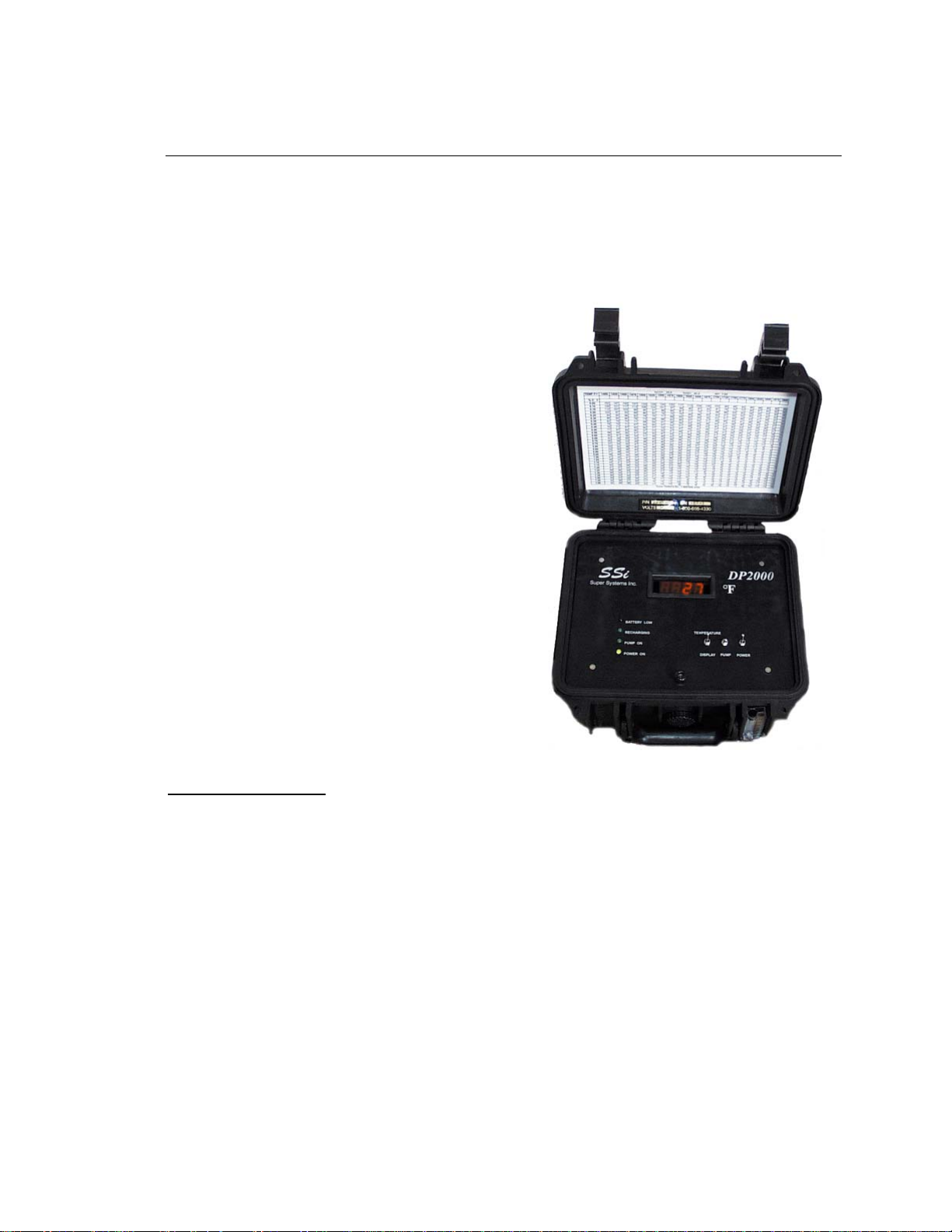
Model DP 2000
Portable Digital Dew Point Analyzer
For measurement of:
● Endothermic Atmosphere
● Endothermic Generators
● Nitrogen / Methanol Atmosphere
● Nitrogen / Hydrogen Atmosphere
● Plant Air Systems
SPECIFICATIONS –
Measurement Range: 0 to +80°F (-18 to +27°C)
Temperature Range: 0 to +120°F (-18 to +49°C)
Power Supply: Factory set to 115 or 240 VAC
Display Type: LED Digital
Display Resolution: +/- 1°F (+/- 0.1°C)
Retransmission Output: 4 –20 mA (range is –50 to +80°F)
Battery Specifications: 12 V Rechargeable
Battery Life: Approximately 8 hours
Size (Closed Case): 11” x 10” x 7”
Weight: 8.2 lbs (3.7 kg)
SSi Manual 4545 – DP2000 Super Systems, Inc. Page # 1 of 17
Revision Level “F” (800
) 666-4330
Page 2

SSi Super Systems Inc.
Product Manual - Model DP2000 Portable Dew Point Analyzer
TABLE OF CONTENTS –
SPECIFICATIONS –..................................................................................................................................1
TABLE OF CONTENTS –.........................................................................................................................2
INTRODUCTION – ...................................................................................................................................2
WARNINGS –............................................................................................................................................2
STARTUP –................................................................................................................................................3
OPERATION - ...........................................................................................................................................3
I
NSTRUMENT DAMAGE –..............................................................................................................................4
WHAT IS DEW POINT? ...........................................................................................................................5
HOW IT WORKS –....................................................................................................................................5
MAINTENANCE / SAFETY ISSUES –....................................................................................................6
FACTORY CALIBRATION –...................................................................................................................6
FIELD CALIBRATION – ..........................................................................................................................6
RECHARGING THE MODEL DP2000 – ...............................................................................................12
RETURNING THE UNIT TO SS
SPARE PARTS –......................................................................................................................................14
APPENDIX “A” – ....................................................................................................................................15
APPENDIX “B” –.....................................................................................................................................16
I –.........................................................................................................13
INTRODUCTION –
Thank you for selecting Super Systems Inc. and the DP2000 as your source for accurate
dew point measurements.
We have taken every precaution to protect this unit during shipment. It has been packed
in a customized foam carrier to protect it against mishandling during shipment. Please
retain this packing material to use when returning the instrument to SSi for calibration or
service. Carefully unpack the Model DP2000 Dew Point Analyzer, and if there are any
signs of shipping damage, notify SSi and the shipper immediately.
Keep this instruction book in a secure place and refer to it when there is a question about
the analyzer. An electronic version of this manual can be downloaded for free from our
website: www.supersystems.com.
WARNINGS –
Although it is intended for use in an industrial environment, the DP2000 is a sensitive
piece of analysis equipment. Care should be taken not to drop the analyzer or to operate
it in a manner inconsistent with its intended use.
• Open all sample ports and remove all soot and/or moisture from the lines prior to
attaching the sample tubing.
• The analyzer must be stored at ambient temperature (65-80°F) for at least four hours
prior to operation.
SSi Manual 4545 – DP2000 Super Systems, Inc. Page # 2 of 17
Revision Level “F” (800
) 666-4330
Page 3

SSi Super Systems Inc.
Product Manual - Model DP2000 Portable Dew Point Analyzer
• When the unit is to be returned to SSi for service or any other reason, it should be
shipped in its original protective packaging. If this packaging is not available, protect
the instrument with at least four inches of foam or other impact-absorbing material.
• For maximum battery life, do not charge the unit until the “battery low” indicator on
the display is illuminated.
• This unit is not designed to measure the dew points in corrosive gasses, such as
Ammonia, S03, Chlorine, and HCL.
• Please read and understand this Product Manual before operating the unit.
Failure to comply with these conditions may cause damage to the unit that will not be
covered under the warranty. Super Systems, Inc. is not responsible for damage to this
unit caused by disregard of these warnings, neglect, or misuse.
STARTUP –
The DP2000 Dew Point Analyzer has been calibrated and fully charged before it was
shipped from Super Systems, Inc. You can begin typical operation as soon as the unit has
been allowed to stabilize in a temperature similar to the temperature in the heat-treating
department. This is particularly important for units that may have been sitting overnight
in a delivery van in sub-zero weather, since the rapid temperature change can cause
condensation on the sensor which will cause the unit to temporarily display inaccurate
readings.
OPERATION -
The use of the DP2000 is somewhat dependent upon the application. Although they are
fundamentally alike, the operation procedures are different for sampling heat treating
furnaces and endothermic generators. Regardless of the application, allow the DP2000 to
operate for two to three minutes before recording any data. This assures that the sensor
has achieved equilibrium in the sample gas. Also, make sure that the in-line filter (P/N
31033 or equivalent) is clean and functional. Not only will this ensure that the sample
reading is not abnormally high (since soot tends to trap moisture), but it will also prevent
soot and other contaminants from entering the unit and damaging the sensor. The
optimum flow rate of the sample gas should be between 1.5 and 2.0 Standard Cubic Feet
per Hour (SCFH), although a flow rate as low as 1.0 SCFH is acceptable. If the unit is
reading less than 1.0 SCFH, verify that there are no obstructions to the flow such as a
clogged sample line or a poorly adjusted knob on the DP2000’s flow meter. If these
conditions do not exist, the unit may need to be returned to SSi for replacement of the
pump. The pump’s life is dependent upon how frequently it is used as well as the
cleanliness of the sample gas. Insufficient filtration will significantly reduce the
operating life of the pump.
SSi Manual 4545 – DP2000 Super Systems, Inc. Page # 3 of 17
Revision Level “F” (800
) 666-4330
Page 4

SSi Super Systems Inc.
Product Manual - Model DP2000 Portable Dew Point Analyzer
Heat Treat Furnace Sampling: A gas sample may be extracted from a process using the
built-in pump. The sample tube from which the sample is taken out of the furnace should
extend into the furnace past the HOT face of the refractory. For accurate results, a
designated sample port should be used to extract the sample. SSi offers a sample port
assembly (part number 20263) which is ideal for this purpose. If a designated sample
port is not available, then a clean “burn-off” port on a Gold Probe™, an industry leading
oxygen sensor for atmosphere control, can be used. Readings taken from the burnoff port
on a probe may be artificially high due to the presence of soot in the probe sheath.
Endothermic Generator Sampling: For applications under pressure, the pump should be
switched off and the flow controlled by the small restriction valve on the flow meter. A
flow rate between 1.5 and 2.0 SCFH is ideal. The sample should be taken from the
endothermic gas manifold after the gas has been cooled. NOTE: Allow the sample port
to blow out any soot and / or water before connecting the sample tube. Failure to do
so will result in inaccurate readings and expose the sensor to potential damage.
Instrument Damage –
The two main causes of damage to the DP2000 are the ingestion of soot and water. Both
of these contaminants will cause erroneous readings in the short term, and cause longterm damage to the sensor and internal components.
Soot / Particulate Contaminants
When taking a sample from a furnace or a generator, care should be taken to reduce the
amount of soot that enters the instrument. The in-line filter will trap these particles, but
cleaning the sample line before attaching the DP2000 will increase the life of the filter.
Furnace ports can be burned off by pumping air through them while hot, or by removing
them from the heat and mechanically cleaning them. Generator ports should be opened
before the instrument is attached to allow any particulate buildup to be blown out. It is
also helpful to tap on the port while it is being blown out to eject any loose particles
before the instrument is attached.
If soot is allowed to collect on the dew point sensor in the instrument, it could result in
higher readings. This soot will also retain moisture than can corrode the sensor over
time. The sensor tip can be cleaned by carefully removing it from the sample block (see
Section 2.3 of the Field Calibration instructions) and rinsing it in isopropyl alcohol. The
power should be off while this is done, and the power should remain off for at least 30
minutes after this procedure to allow all of the alcohol to completely evaporate.
Water / Moisture Contamination
When a furnace or generator is being started up or cooled down, the resulting gases will
contain unusually high amounts of CO2. When these gases cool, moisture will
precipitate out and become condensation inside the sample tubing assembly. Even if the
SSi Manual 4545 – DP2000 Super Systems, Inc. Page # 4 of 17
Revision Level “F” (800
) 666-4330
Page 5

SSi Super Systems Inc.
Product Manual - Model DP2000 Portable Dew Point Analyzer
furnace or generator is operating normally, residual moisture may still be present in the
sample tube or plumbing system. In the same way that the ports are checked for soot (see
above) they should be checked for moisture before attaching the instrument. This is
especially important when taking a sample from a generator, since the sample port is
usually preceded by a significant amount of plumbing. All traces of moisture should be
eliminated before attaching the instrument. Failure to do so will result in erroneous
measurements and could result in damage to the analyzer.
The first signs of moisture in the instrument will be visible condensation in the sample
tubing and an unusually high dew point. The upper range of the sensor is +80°F, so if
that value is displayed on the instrument it is probably due to the presence of moisture. If
this moisture is not removed, it will cause the sensor tip to corrode and will eventually
require the sensor to be replaced.
To remove moisture from the instrument, the sample tubing and filter should be removed
from the instrument since they will probably be wet. An inert gas such as Nitrogen or
Argon should then be flowed through the instrument (with the pump off) for as much
time as it takes to dry out. This dry-out time will depend on the amount of moisture
present in the instrument. The condition of the sensor can be monitored by periodically
reading the dew point from the display and watching the value decrease over time. To
test if it is operating properly, verify the ambient dew point against a web-based weather
station that will report the ambient dew point for your area. If the displayed reading is
within three degrees of the reported dew point when the instrument is taken outside, then
all of the moisture has probably been successfully removed. The wet filter and sample
tubing can be re-attached after they have been completely dried out.
To prevent the possibility of moisture damaging the instrument, be sure that the measured
dew point is below ambient levels before it is stored. If necessary, Nitrogen or Argon can
be used to dry out the instrument after use.
WHAT IS DEW POINT?
Dew point can be defined as the temperature at which the water vapor pressure of the gas
equals the saturated water vapor pressure. In other words, it is the temperature at which
condensation will just begin to occur as the gas is cooled. Dew point and relative
humidity are not the same measurement. Relative humidity is the amount of water vapor
in the air compared to the amount the air could hold if it was totally saturated, and it is
expressed as a percentage, not a temperature. To determine dew point, two main
variables are required: Relative Humidity and Temperature. The DP2000 measures both
variables to compute the displayed dew point.
HOW IT WORKS –
The dew point sensor is a “dielectric ceramic” that varies its electrical capacitance with
changes in relative humidity. The sensor is mounted in a short probe, which is installed
in a T-fitting that allows the sample gas to flow past the sensor. The tip of this probe
SSi Manual 4545 – DP2000 Super Systems, Inc. Page # 5 of 17
Revision Level “F” (800
) 666-4330
Page 6

SSi Super Systems Inc.
Product Manual - Model DP2000 Portable Dew Point Analyzer
contains the dielectric ceramic relative humidity (RH) sensor, as well as a built in
temperature sensor to determine its dry bulb temperature. Information from both of these
sensors is used to compute the resultant dew point, which is displayed on the digital LED
display.
MAINTENANCE / SAFETY ISSUES –
One of the added features of the DP2000 is the ability to monitor the sensor’s operating
temperature through the built-in thermister in the probe tip. The temperature of the
sample gas can be determined by pressing the switch labeled “Sensor Temp”. It is spring
loaded, so it will automatically return to displaying dew point.
Maintaining proper sensor temperature will prevent the premature failure of the sensor.
The operating temperature of the sensor should remain below 140° F (60°C) at all times.
Periodic checks of the sensor temperature will verify that the sensor is not being exposed
to excessive heat. If these periodic checks show a high sensor temperature, then the
length of sample tubing should be increased to allow for adequate cooling of the sample
before it passes the sensor tip.
Continuous operation of the DP2000 Dew Point Analyzer will lead to premature failure,
since many the internal components are not designed for uninterrupted use. If continuous
monitoring of Dew Points is required, please contact Super Systems, Inc. at (800) 6664330 to inquire about products intended specifically for this application.
FACTORY CALIBRATION –
Factory calibration is recommended every six months if the unit is used regularly. SSi’s
calibration is NIST traceable and includes a numbered “Certificate of Calibration”. This
certificate also indicates the accuracy of the analyzer before and after calibration. Please
contact Super Systems, Inc. at (800) 666-4330 for more information regarding this
service.
FIELD CALIBRATION –
It is also possible to calibrate the DP2000 in the field, which will require the optional
calibration kit (Part Number 31030). The instructions for a field calibration are shown
here, however please feel free to contact Super Systems at 800-666-4330 if you would
like to review the process with us before you begin.
The calibration kit consists of two bottles of saturated salt solution in which each bottle
generates a precise relative humidity percentage (R.H.%) value. One bottle is 11.3%
R.H., and the other is 75.3% R.H. These two specific calibration points are already preprogrammed into the microprocessor board.
1.0 Open the unit
SSi Manual 4545 – DP2000 Super Systems, Inc. Page # 6 of 17
Revision Level “F” (800
) 666-4330
Page 7

SSi Super Systems Inc.
Product Manual - Model DP2000 Portable Dew Point Analyzer
1.1 Remove the aluminum faceplate of the DP2000 by removing the single
allen-head cap screw located at the bottom front of the faceplate. After the
screw has been removed, carefully lift the front of the faceplate and slide it
towards you about an inch. After the faceplate has been removed, it can
temporarily be rested in the lid of the open case, to allow access to the
components inside. This plate will still be connected to the interior circuit
boards, so care should be taken to maintain all existing connections.
2.0 Locate the key components within the unit
2.1 The microprocessor board is located in the front left side of the unit.
This board contains three very small buttons that are used for calibration.
Two are next to one another, and they are marked “75.3%” and “11.3%”,
while the other has no label. The unmarked button is the “Calibrate” button.
The approximate locations of each button are shown on this diagram:
SPAN
BUTTON
(75.3)
Dew Point Microprocessor Board
CAL
BUTTON
ZERO
BUTTON
(11.3)
2.2 The sensor-sampling chamber is located in the back left of the unit. It is
the gray rectangular box with brass barb fittings on either side with a black
plastic gland protruding from the center.
2.3 The sensor probe is positioned in the sensor-sampling chamber. It is held
in place by the nut on the black plastic gland.
3.0 Remove the sensor probe from the sensor sampling chamber.
3.1 Loosen the black plastic gland nut and slowly slide the sensor probe out
through the airtight seal. Care must be taken when removing this sensor probe,
SSi Manual 4545 – DP2000 Super Systems, Inc. Page # 7 of 17
Revision Level “F” (800
) 666-4330
Page 8

SSi Super Systems Inc.
Product Manual - Model DP2000 Portable Dew Point Analyzer
since the tip is very delicate and can be easily damaged if it is mishandled.
Note that the probe has white mark at the wire entry point, which must be
aligned with corresponding white mark in plastic gland when it is re-inserted
in the sampling chamber.
4.0 Install the sensor probe into the 75.3% salt solution.
4.1 Slip the black sensor gland (supplied in the calibration kit) over the sensor
probe with the sensor tip protruding from the threaded end of the gland and
the sensor wires being flush with the top of the rubber o-ring in the gland.
Tighten the gland around the sensor. This does not need to be done with a
wrench or other tools, but it does need to be tight enough to prevent ambient
air from contaminating the humidity level of the sampling chamber.
4.2 Remove the cap of the 75.3% salt solution and install the sensor gland
(with the sensor) into the salt solution. To increase the life of the calibration
salts, an effort should be made to minimize the amount of time that the salt
solution is exposed to the ambient air.
5.0 Allow the sensor to reach equilibrium with the calibration salt.
5.1 With the power to the unit still turned off, leave the sensor in the
calibration salt for a minimum of eighteen (18) hours. It is acceptable to leave
the sensor in the salt solution for a longer period of time, even a few days, if
desired.
6.0 Begin the 75.3% (Span) calibration process.
6.1 After leaving the sensor in the salt for at least eighteen (18) hours, turn the
unit on. The reading on the display is not important at this point.
6.2 Simultaneously press the “75.3%” and “Calibration” buttons on the
microprocessor board.
7.0 Verify the 75.3% (Span) calibration.
7.1 Do not be concerned if the unit does not display 75.3, since it is not
supposed to match the value of the calibration salt.
7.2 Use the “Sensor Temp” switch on the faceplate of the unit to determine and
record the sensor temperature.
SSi Manual 4545 – DP2000 Super Systems, Inc. Page # 8 of 17
Revision Level “F” (800
) 666-4330
Page 9

SSi Super Systems Inc.
Product Manual - Model DP2000 Portable Dew Point Analyzer
7.3 Look up this temperature on the “Theoretical Dew Point Values for
Calibration Verification” chart located in the back of this manual. Appendix
“A” will show the temperature values in Fahrenheit, and Appendix B will
show the temperature values in Celsius.
7.4 Next to the appropriate temperature, note the number in the corresponding
column titled “75.3%”. This should match with the dew point that is shown
on the display of the DP2000.
8.0 Determine the acceptability of the reading.
8.1 The value printed on the chart in Appendix A is a theoretical value, and
some variation can be expected. When a calibration is performed at SSi, we
certify (in writing) that the unit displays within +/- 1 degree of the theoretical
value after it has been calibrated. We would not consider a calibration to be
successful unless it is within +/- 1 degree, however in the case of a field
calibration, this degree of accuracy may or may not be required. The degree
of accuracy that is acceptable is determined by the policy of the person
performing the calibration.
NOTE: Keep in mind that the DP2000 only displays even numbers, and not
tenths of a degree. Therefore, a reading of 65°F could be as low as 64.50 or
as high as 65.49.
9.0 Allow the sensor to achieve equilibrium at ambient atmosphere.
9.1 After the 75.3% (Span) calibration has been completed, remove the sensor
from the calibration salt and replace the cap on the salt.
9.2 Leave the sensor probe in the gland and while the unit is still on, allow it
to achieve equilibrium at the ambient atmosphere in the room. This is
accomplished by simply leaving the sensor exposed to ambient air for
between two and three minutes. You will know when this has been
accomplished when the numbers on the display begin to stabilize.
10.0 Install the sensor probe into the 11.3% salt solution.
SSi Manual 4545 – DP2000 Super Systems, Inc. Page # 9 of 17
Revision Level “F” (800
) 666-4330
Page 10

SSi Super Systems Inc.
Product Manual - Model DP2000 Portable Dew Point Analyzer
10.1 Remove the cap of the 11.3% salt solution and install the sensor gland
(with the sensor) into the salt solution. To increase the life of the calibration
salts, an effort should be made to minimize the amount of time that the salt
solution is exposed to the ambient air.
10.2 Turn the unit off.
11.0 Allow the sensor to reach equilibrium with the calibration salt.
11.1 With the power to the unit still turned off, leave the sensor in the
calibration salt for a minimum of 24 hours. It is acceptable to leave the
sensor in the salt solution for a longer period of time, even a few days, if
desired.
12.0 Begin the 11.3% (Zero) calibration process
12.1 After leaving the sensor in the salt for at least twenty-four (24) hours, turn
the unit on. The reading on the display is not important at this point.
12.2 Simultaneously press the “11.3%” and “Calibration” buttons on the
microprocessor board.
13.0 Verify the 11.3% (Zero) calibration
13.1 Do not be concerned if the unit does not display 11.3, since it is not
supposed to match the value of the calibration salt.
13.2 Use the “Sensor Temp” switch on the faceplate of the unit to determine
and record the sensor temperature.
13.3 Look up this temperature on the “Theoretical Dew Point Values for
Calibration Verification” chart located in the back of this manual. Appendix
“A” will show the temperature values in Fahrenheit, and Appendix B will
show the temperature values in Celsius.
13.4 Next to the appropriate temperature, note the number in the corresponding
column titled “11.3%”. This should match with the dew point that is shown
on the display of the DP2000.
SSi Manual 4545 – DP2000 Super Systems, Inc. Page # 10 of 17
Revision Level “F” (800
) 666-4330
Page 11

SSi Super Systems Inc.
Product Manual - Model DP2000 Portable Dew Point Analyzer
14.0 Determine the acceptability of the reading
14.1 The value printed on the chart in Appendix A is a theoretical value, and
some variation can be expected. When a calibration is performed at SSi, we
certify (in writing) that the unit displays within +/- 1 degree of the theoretical
value after it has been calibrated. We would not consider a calibration to be
successful unless it is within +/- 1 degree, however in the case of a field
calibration, this degree of accuracy may or may not be required. The degree
of accuracy that is acceptable is determined by the policy of the person
performing the calibration.
NOTE: Keep in mind that the DP2000 only displays even numbers, and not
tenths of a degree. Therefore, a reading of 18°F could be as low as 17.50 or
as high as 18.49.
15.0 Allow the sensor to achieve equilibrium at ambient atmosphere
15.1 After the 11.3% (Zero) calibration has been completed, remove the sensor
from the calibration salt and replace the cap.
15.2 Leave the sensor probe in the gland and while the unit is still on, allow it
to achieve equilibrium at the ambient atmosphere in the room. This should
take between two and three minutes. You will know when this has been
accomplished when the numbers on the display begin to stabilize.
16.0 Re-assemble the unit
16.1 After the calibration process has been completed, remove the sensor probe
from the gland and return it to the sensor-sampling chamber, taking care to
position it properly. The white mark on the sensor probe should face towards
the right of the sensor-sampling chamber (at 3:00 if it were the face of a
clock.). If the white mark is not visible, then it should be placed so the sample
flow directly strikes the face of the mirror on the sensor tip (the sample flows
from right-to-left). In other words, the mirror should face the incoming gas
stream.
16.2 Hand-tighten the black sensor gland to prevent air from leaking out of the
sampling chamber.
SSi Manual 4545 – DP2000 Super Systems, Inc. Page # 11 of 17
Revision Level “F” (800
) 666-4330
Page 12

SSi Super Systems Inc.
Product Manual - Model DP2000 Portable Dew Point Analyzer
16.3 Slide the faceplate into position with the back posts going into the
corresponding holes as the faceplate slides back.
16.4 Verify that the system is leak proof by turning on the pump and placing a
finger over the sample inlet port. The flow meter on the side of the unit will
drop to zero if there are no leaks. If a leak is detected, make sure that all
tubing connections are tight, especially the black sensor gland.
16.5 After the unit has passed the leak test, re-fasten the screw into the
faceplate and tighten it.
17.0 Make sure that all caps are replaced on the calibration salts, and return the
DP2000 to service.
RECHARGING THE MODEL DP2000 –
The internal 12V gel cell battery has enough power to run the analyzer for approximately
8 hours, although after many charge/discharge cycles some loss of battery life can be
expected. When it is time to recharge the unit, a red “Battery Low” light will illuminate.
When this light comes on, the unit will operate for an additional one to two hours before
the battery is unable to power the unit and it shuts off.
A full recharge will take 16 hours, however the analyzer can be used while it is
recharging. It can also be left on charge for as long as you want, with no harm to the
battery. A green “Recharging” light will come on to verify that the unit is charging, and
this light will go out automatically when it is completely charged.
For maximum battery life, it is recommended that the battery be discharged before it is
recharged. The battery does not need to be completely discharged however, there is a
correlation between the number of times that a battery is charged and the life span of the
battery. By keeping the number of times the battery is recharged to a minimum, the
battery life can be increased.
To charge the analyzer, plug the power cord into any 110 VAC outlet.
The instrument is not intended for use with 220 VAC power unless it has been
specifically set up accordingly at the factory. If this has been done, the serial number
plate will indicate 220VAC operation.
SSi Manual 4545 – DP2000 Super Systems, Inc. Page # 12 of 17
Revision Level “F” (800
) 666-4330
Page 13

SSi Super Systems Inc.
Product Manual - Model DP2000 Portable Dew Point Analyzer
RETURNING THE UNIT TO SSi –
This analyzer contains some components that may require periodic replacement based on
the amount of use that the unit experiences and the methods in which it is used. If service
on the unit is necessary, it should be sent back to Super Systems, Inc. in the original
packaging for repair. If the original packaging is not available, the analyzer should be
surrounded by impact-absorbing materials and placed in a box. It is the responsibility of
the shipper to ensure that the DP2000 arrives at SSi undamaged.
Before shipping the analyzer, please call (800) 666-4330 to receive a Return Materials
Authorization (RMA) number. The shipping address that should be used for returns is:
Super Systems, Inc.
ATTN: RMA #XXXX
7205 Edington Drive
Cincinnati, OH 45249
SSi Manual 4545 – DP2000 Super Systems, Inc. Page # 13 of 17
Revision Level “F” (800
) 666-4330
Page 14

SSi Super Systems Inc.
Product Manual - Model DP2000 Portable Dew Point Analyzer
SPARE PARTS –
To simplify the ordering of replacement parts, the following is a list of some of the
components that may be requested:
Description Part Number
Factory Calibration 13045
Calibration Kit 31030
Filter 31033
Rechargeable Battery 31037
Dew Point Sensor 31038
Microprocessor Display Board 31501
Power Cord 33018
Flow meter 36033
Sample Pump 37119
Flexible Sample Tubing Assembly w/Filter A20104
Cell Sampling Block 20192
Sample Tube (wand and valves) 20263
SSi Manual 4545 – DP2000 Super Systems, Inc. Page # 14 of 17
Revision Level “F” (800
) 666-4330
Page 15

Product Manual - Model DP2000 Portable Dew Point Analyzer
APPENDIX “A” –
SSi Super Systems Inc.
Theoretical Dew Point Values For Calibration Verification (Fahrenheit)
Temp Temp Temp
o
(
F)
69.00
69.10
69.20
69.30
69.40
69.50
69.60
69.70
69.80
69.90
70.00
70.10
70.20
70.30
70.40
70.50
70.60
70.70
70.80
70.90
71.00
71.10
71.20
71.30
71.40
71.50
71.60
71.70
71.80
71.90
72.00
72.10
72.20
72.30
72.40
72.50
72.60
Percent RH Percent RH Percent RH
11.3% 75.3%
12.94 60.86
13.01 60.96
13.09 61.06
13.17 61.16
13.25 61.25
13.33 61.35
13.40 61.45
13.48 61.54
13.56 61.64
13.63 61.74
13.71 61.83
13.79 61.93
13.87 62.03
13.95 62.12
14.02 62.22
14.10 62.32
14.18 62.41
14.26 62.51
14.33 62.60
14.41 62.70
14.49 62.80
14.57 62.89
14.65 62.99
14.72 63.09
14.80 63.18
14.88 63.28
14.96 63.38
15.03 63.47
15.11 63.57
15.19 63.67
15.27 63.76
15.34 63.86
15.42 63.96
15.50 64.05
15.58 64.15
15.65 64.25
15.73 64.34
o
(
F)
72.70
72.80
72.90
73.00
73.10
73.20
73.30
73.40
73.50
73.60
73.70
73.80
73.90
74.00
74.10
74.20
74.30
74.40
74.50
74.60
74.70
74.80
74.90
75.00
75.10
75.20
75.30
75.40
75.50
75.60
75.70
75.80
75.90
76.00
76.10
76.20
76.30
11.3% 75.3%
15.81 64.44
15.89 64.54
15.97 64.63
16.04 64.73
16.12 64.82
16.20 64.92
16.28 65.02
16.35 65.11
16.43 65.21
16.51 65.31
16.59 65.40
16.66 65.50
16.74 65.60
16.82 65.69
16.90 65.79
16.97 65.89
17.05 65.98
17.13 66.08
17.21 66.18
17.28 66.27
17.36 66.37
17.44 66.47
17.52 66.56
17.59 66.66
17.67 66.76
17.75 66.85
17.83 66.95
17.90 67.04
17.98 67.14
18.06 67.24
18.14 67.33
18.21 67.43
18.29 67.53
18.37 67.62
18.44 67.72
18.52 67.82
18.60 67.91
o
(
F)
76.40
76.50
76.60
76.70
76.80
76.90
77.00
77.10
77.20
77.30
77.40
77.50
77.60
77.70
77.80
77.90
78.00
78.10
78.20
78.30
78.40
78.50
78.60
78.70
78.80
78.90
79.00
79.10
79.20
79.30
79.40
79.50
79.60
79.70
79.80
79.90
80.00
11.3% 75.3%
18.68 68.01
18.75 68.11
18.83 68.20
18.91 68.30
18.99 68.40
19.06 68.49
19.14 68.59
19.22 68.69
19.30 68.78
19.37 68.88
19.45 68.97
19.53 69.07
19.61 69.17
19.68 69.26
19.76 69.36
19.84 69.46
19.91 69.55
19.99 69.65
20.07 69.75
20.14 69.84
20.22 69.94
20.30 70.04
20.38 70.13
20.46 70.23
20.53 70.33
20.61 70.42
20.69 70.52
20.76 70.61
20.84 70.71
20.92 70.81
21.00 70.90
21.07 71.00
21.15 71.10
21.23 71.19
21.31 71.29
21.38 71.39
21.46 71.48
SSi Manual 4545 – DP2000 Super Systems, Inc. Page # 15 of 17
Revision Level “F” (800
) 666-4330
Page 16

Product Manual - Model DP2000 Portable Dew Point Analyzer
APPENDIX “B” –
SSi Super Systems Inc.
Theoretical Dew Point Values For Calibration Verification (Celsius)
Temp Temp Temp
o
(
C)
20.56
20.61
20.67
20.72
20.78
20.83
20.89
20.94
21.00
21.06
21.11
21.17
21.22
21.28
21.33
21.39
21.44
21.50
21.56
21.61
21.67
21.72
21.78
21.83
21.89
21.94
22.00
22.06
22.11
22.17
22.22
22.28
22.33
22.39
22.44
22.50
22.56
Percent RH
11.3% 75.3%
-10.59 16.03
-10.55 16.09
-10.51 16.14
-10.46 16.20
-10.42 16.25
-10.37 16.31
-10.33 16.36
-10.29 16.41
-10.24 16.47
-10.21 16.52
-10.16 16.57
-10.12 16.63
-10.07 16.68
-10.03 16.73
-9.99 16.79
-9.94 16.84
-9.90 16.89
-9.86 16.95
-9.82 17.00
-9.77 17.06
-9.73 17.11
-9.68 17.16
-9.64 17.22
-9.60 17.27
-9.56 17.32
-9.51 17.38
-9.47 17.43
-9.43 17.48
-9.38 17.54
-9.34 17.59
-9.29 17.64
-9.26 17.70
-9.21 17.76
-9.17 17.81
-9.12 17.86
-9.08 17.92
-9.04 17.97
o
(
C)
22.61
22.67
22.72
22.78
22.83
22.89
22.94
23.00
23.06
23.11
23.17
23.22
23.28
23.33
23.39
23.44
23.50
23.56
23.61
23.67
23.72
23.78
23.83
23.89
23.94
24.00
24.06
24.11
24.17
24.22
24.28
24.33
24.39
24.44
24.50
24.56
24.61
Percent RH Percent RH
11.3% 75.3%
-8.99 18.02
-8.95 18.08
-8.91 18.13
-8.87 18.18
-8.82 18.23
-8.78 18.29
-8.73 18.34
-8.69 18.39
-8.65 18.45
-8.61 18.51
-8.56 18.56
-8.52 18.61
-8.48 18.67
-8.43 18.72
-8.39 18.77
-8.35 18.83
-8.31 18.88
-8.26 18.93
-8.22 18.99
-8.18 19.04
-8.13 19.09
-8.09 19.15
-8.04 19.20
-8.01 19.26
-7.96 19.31
-7.92 19.36
-7.87 19.42
-7.83 19.47
-7.79 19.52
-7.74 19.58
-7.70 19.63
-7.66 19.68
-7.62 19.74
-7.57 19.79
-7.53 19.84
-7.49 19.90
-7.44 19.95
o
(
C)
24.67
24.72
24.78
24.83
24.89
24.94
25.00
25.06
25.11
25.17
25.22
25.28
25.33
25.39
25.44
25.50
25.56
25.61
25.67
25.72
25.78
25.83
25.89
25.94
26.00
26.06
26.11
26.17
26.22
26.28
26.33
26.39
26.44
26.50
26.56
26.61
26.67
11.3% 75.3%
-7.40 20.01
-7.36 20.06
-7.32 20.11
-7.27 20.17
-7.23 20.22
-7.19 20.27
-7.14 20.33
-7.10 20.38
-7.06 20.43
-7.02 20.49
-6.97 20.54
-6.93 20.59
-6.88 20.65
-6.84 20.70
-6.80 20.76
-6.76 20.81
-6.72 20.86
-6.67 20.92
-6.63 20.97
-6.59 21.02
-6.54 21.08
-6.50 21.13
-6.46 21.18
-6.41 21.24
-6.37 21.29
-6.33 21.34
-6.28 21.40
-6.24 21.45
-6.20 21.51
-6.16 21.56
-6.11 21.61
-6.07 21.67
-6.03 21.72
-5.98 21.77
-5.94 21.83
-5.90 21.88
-5.86 21.93
SSi Manual 4545 – DP2000 Super Systems, Inc. Page # 16 of 17
Revision Level “F” (800
) 666-4330
Page 17

SSi Super Systems Inc.
Product Manual - Model DP2000 Portable Dew Point Analyzer
REVISION HISTORY –
Rev. Description Date
A Initial Release 04-24-2001
B Added Revision History Page 07-11-2001
C Updated calibration information, added warnings 06-26-2002
D Revised Warnings. MCO# - 2030 06-16-2003
E SSi address update, general update 04-12-2005
F Added additional warnings and performed general update (MCO
#2038)
03-26-2007
SSi Manual 4545 – DP2000 Super Systems, Inc. Page # 17 of 17
Revision Level “F” (800
) 666-4330
 Loading...