

Page 1

COMPACT HMI AND
COMPACT HMI EDITOR
OPERATIONS MANUAL
Super Systems Inc.
7205 Edington Drive
Cincinnati, OH 45249
513-772-0060
Fax: 513-772-9466
www.supersystems.com
Page 2

Compact HMI and Compact HMI Editor Operations Manual
Super Systems Inc.
Page 2 of 60
Super Systems Inc.
Super Systems Europe
Super Systems Mexico
Super Systems China
USA Office
Corporate Headquarters
7205 Edington Drive
Cincinnati, OH 45249
Phone: (513) 772-0060
http://www.supersystems.com
Sistemas Superiores Integrales S de RL de CV
Querétaro, QRO CP, MEXICO 76120
Phone: +52 (442) 410 9040
http://www.supersystems.com
Units 3 & 4, 17 Reddicap Trading Estate,
Sutton Coldfield, West Midlands
B75 7BU
UNITED KINGDOM
Phone: +44 (0) 121 329 2627
http://www.supersystemseurope.com
No. 335 XianXia Road
Room 308
Shanghai, CHINA
200336
Phone: +86 21 5206 5701/2
http://www.supersystems.com
Page 3

Compact HMI and Compact HMI Editor Operations Manual
Super Systems Inc.
Page 3 of 60
Table of Contents
Introduction ........................................................................................................................................ 5
Compact HMI Editor ........................................................................................................................... 7
Installation ...................................................................................................................................... 7
Prerequisites .............................................................................................................................. 7
Installation Procedure ............................................................................................................... 7
Solution Overview ........................................................................................................................... 9
Panels ............................................................................................................................................. 9
SSi Options ................................................................................................................................ 11
Tags (Tag Management) ............................................................................................................... 12
Expression Editor ......................................................................................................................... 17
Expression Operators, Constants, and Functions ................................................................... 17
Display Conditions ........................................................................................................................ 19
How Conditions are Prioritized ................................................................................................ 23
Controls ........................................................................................................................................ 26
Indicator Label .......................................................................................................................... 27
Control Button .......................................................................................................................... 29
Image Box ................................................................................................................................. 32
Exporting for the Touch Screen ................................................................................................... 33
Interacting with the Touch Screen .............................................................................................. 34
Using the Main Menu ................................................................................................................... 34
File ............................................................................................................................................ 34
Edit ............................................................................................................................................ 35
Format ...................................................................................................................................... 36
Tools .......................................................................................................................................... 36
Help ........................................................................................................................................... 37
Using the Design Environment Toolbar ...................................................................................... 40
Compact HMI (Use on SSi Touch Screen) ....................................................................................... 43
Prerequisites and Installation ..................................................................................................... 43
Use with Compatible Touch Screens ........................................................................................... 43
Example of Compact HMI Touch Screen Application Design and Rendering ............................ 43
Example Designs ...................................................................................................................... 43
Preparing Solution for Touch Screen ...................................................................................... 49
Page 4

Compact HMI and Compact HMI Editor Operations Manual
Super Systems Inc.
Page 4 of 60
Running the Compact HMI Solution......................................................................................... 51
Revision History ............................................................................................................................... 53
Appendix 1: Software Best Practices .............................................................................................. 54
When Configuring Connections and Tags in Compact HMI Editor ............................................. 54
Backing Up Touch Screen Files (.cfxml and .tdx) ....................................................................... 54
When Saving Multiple Solutions .................................................................................................. 54
Backing Up Development Files .................................................................................................... 55
Appendix 2: Font Measurement Units ............................................................................................. 56
Appendix 3: Typical Wiring Diagrams ............................................................................................. 57
Page 5

Compact HMI and Compact HMI Editor Operations Manual
Super Systems Inc.
Page 5 of 60
Introduction
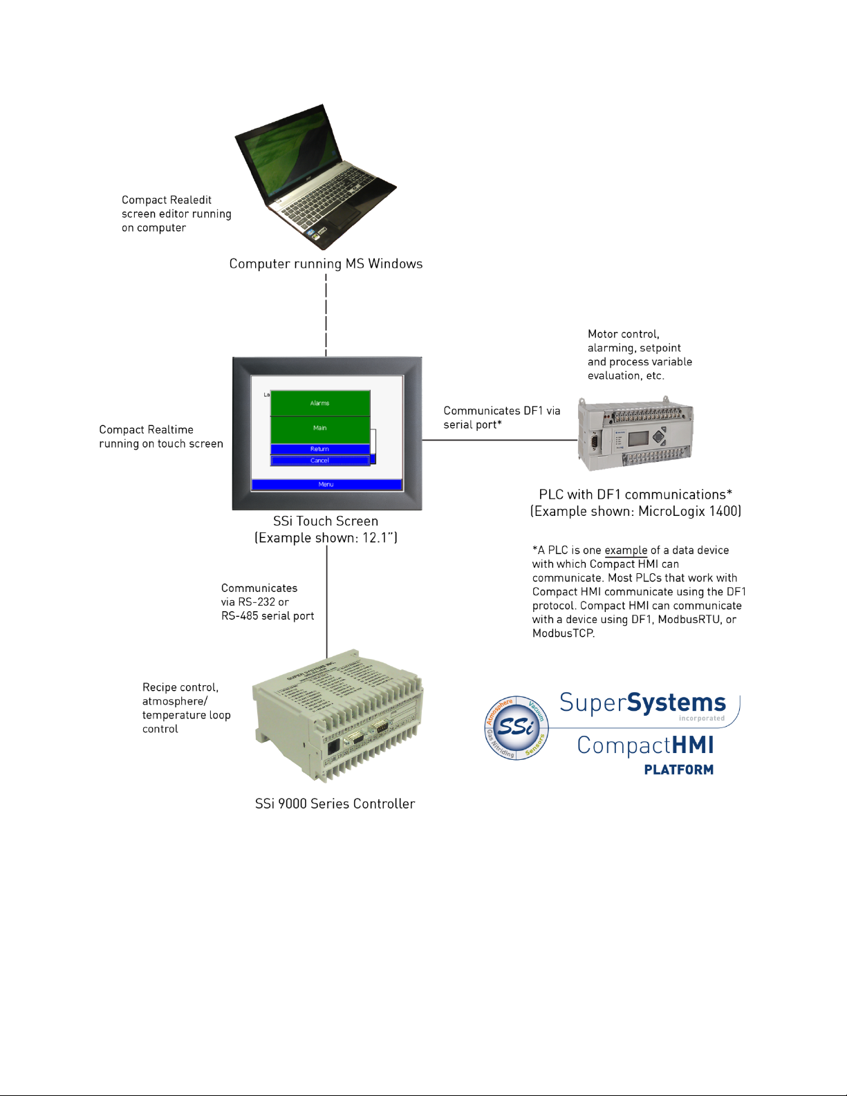
Compact HMI is a software platform that allows you to create customized HMI screens using an
application called
display of equipment, graphical display of process data, and objects used for interaction with
equipment. These screens can then be run on a compatible touch screen that works with Super
Systems Inc. (SSi) 9000 Series controllers. The touch screen application from SSi that provides
the framework for running customized HMI screens is
Compact HMI can handle communications via the Allen-Bradley DF1, Modbus TCP, and Modbus
RTU communication protocols. Using Allen-Bradley DF1, for example, with the touch screen
connected to a compatible data device (such as a MicroLogix 1400 PLC via an RS-232 serial
connection), Compact HMI can perform I/O operations with the data device and can access
register values within the data device. Design tools within Compact HMI Editor allow you to
program evaluations of register values and design multiple panels for use by the operator.
Figure 1 illustrates the components that make up a Compact HMI system.
Compact HMI Editor. A programmed HMI screen can contain a graphical
Compact HMI.
Page 6
Compact HMI and Compact HMI Editor Operations Manual
Super Systems Inc.
Page 6 of 60
Figure 1 - Compact HMI Platform components
Page 7
Compact HMI and Compact HMI Editor Operations Manual
Super Systems Inc.
Page 7 of 60
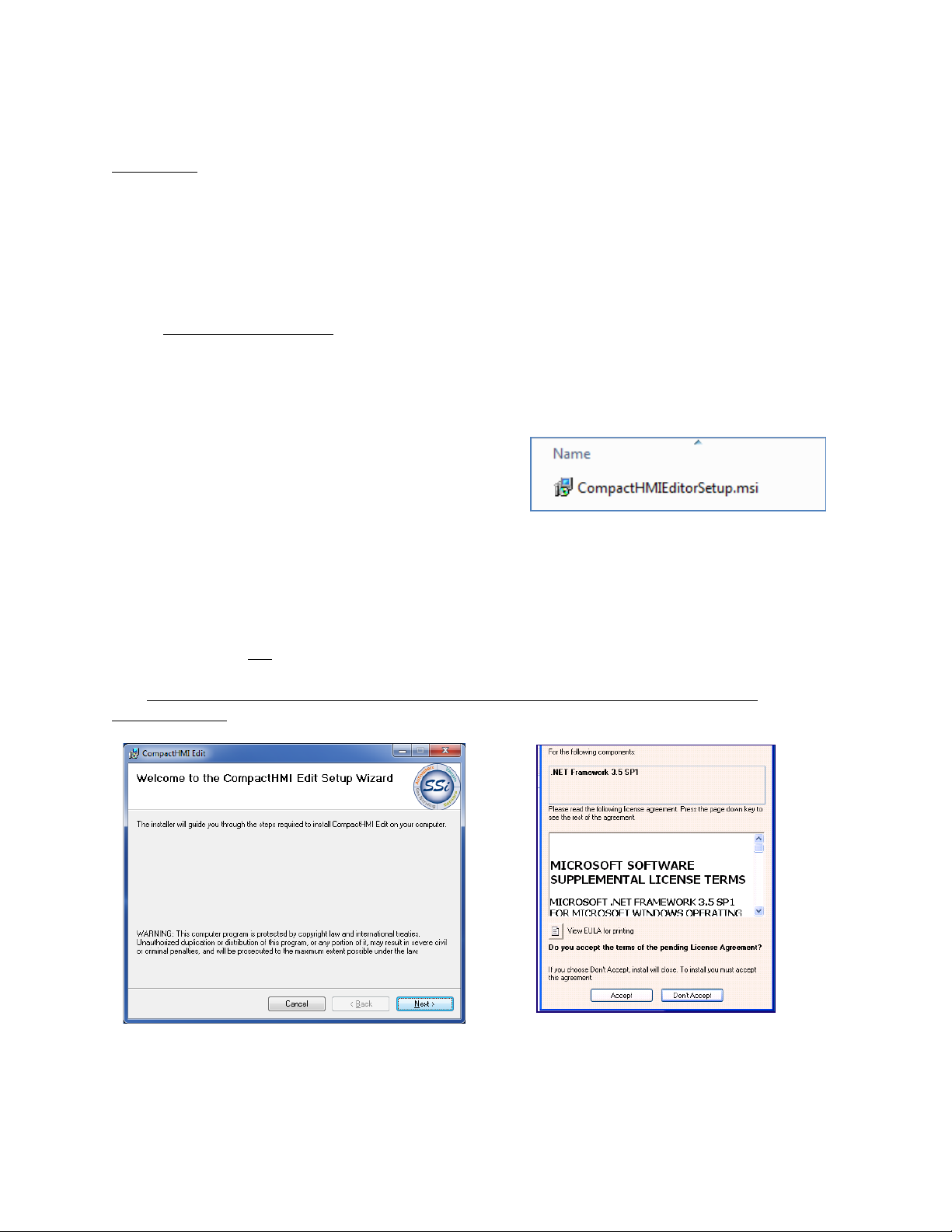
Insert the Compact HMI Editor installation media
those shown in Figure 2.
Figure 2 - Example Installation Files
Figure 3 - Compact HMI Editor Setup Wizard screen
Figure 4 - .NET Framework 3.5 Setup Screen
(will appear if needed)
Compact HMI Editor
Installation
Prerequisites
Compact HMI Editor has prerequisites that must be fulfilled in order for the program to run
properly. These include:
• A computer with Windows XP, Vista, 7, or 8
• Microsoft .NET Framework 3.5. Compact HMI Editor setup will install this package if it is not
already present on the computer where Compact HMI Editor is being installed (see Figure
4
). Version 3.5 is required.
In order to use the screen you create with Compact HMI Editor, you need a Super Systems touch
screen with Compact HMI. Refer to the “Use with Compatible Touch Screens” section for more
details.
Installation Procedure
into the USB port, CD/DVD drive, or other proper
location. Open Windows Explorer and browse to
the folder containing the Compact HMI Editor
installation files. You will see installation files like
Double click on the “CompactHMIEditorSetup.msi” file.
If Microsoft .NET Framework 3.5 is installed, the Setup Wizard will appear (Figure 3
). If .NET
Framework 3.5 is not installed, the Setup Wizard will first prompt you to install .NET
Framework 3.5 (Figure 4). .NET Framework must be installed before Compact HMI Editor is
run. An Internet connection is needed in order to download the required files for .NET
Framework 3.5.
Page 8
Compact HMI and Compact HMI Editor Operations Manual
Super Systems Inc.
Page 8 of 60
The installation URL for .NET Framework 3.5 is http://www.microsoft.com/en-
Setup Wizard.
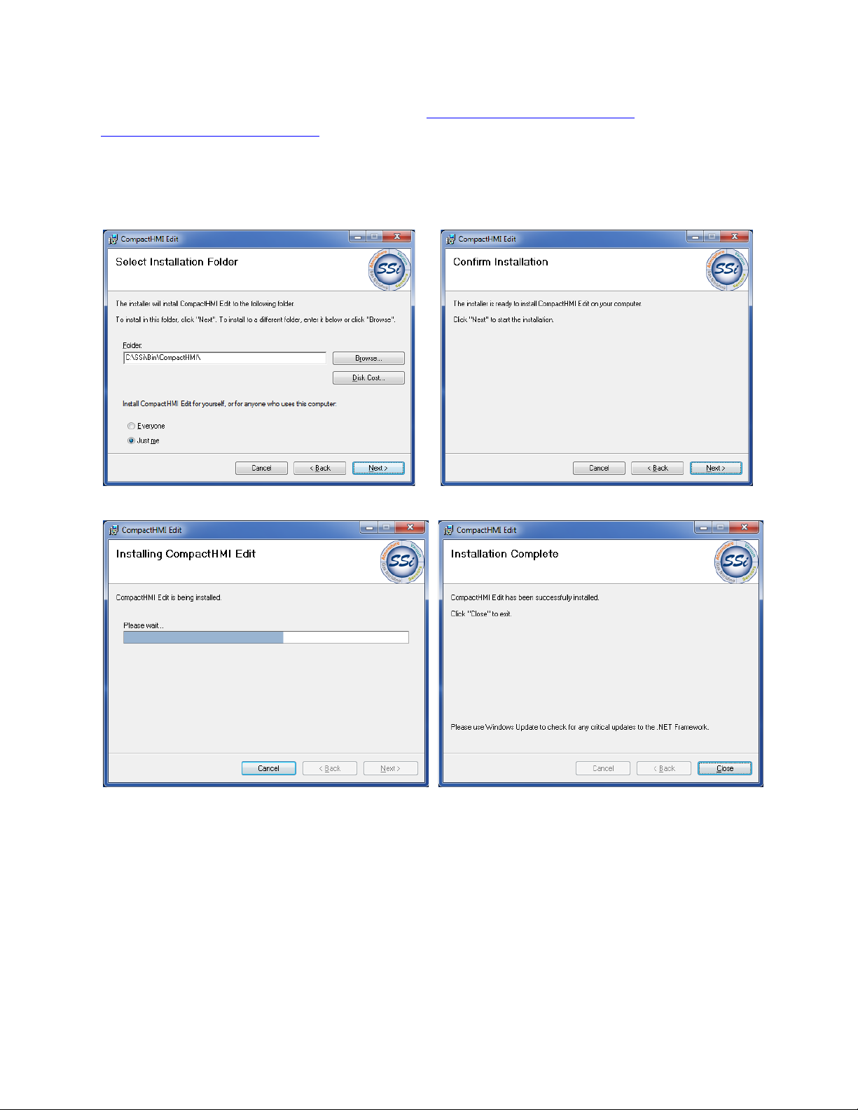
When ready to proceed with installation of Compact HMI Editor, click the Next button on the first
Compact HMI Editor installation (Figure 5).
us/download/details.aspx?id=21, if for some reason it cannot be installed properly using the
screen of the Setup Wizard. The screens below show typical screens that will appear in a
Figure 5 - Compact HMI Editor Setup Screens (in succession)
Once Compact HMI Editor is installed, you may begin using it.
Page 9

Compact HMI and Compact HMI Editor Operations Manual
Super Systems Inc.
Page 9 of 60
Solution Overview
A Solution is a collection of files that will be translated into a complete HMI during runtime.
Each screen within a solution is called a
accessible via the touch screen.
Therefore, a Solution can also be defined as a collection of HMI
Panel. Each Panel represents individual screens
Panels.
Compact HMI Editor creates display files for each Panel. When Compact HMI Editor is first
started, it will load a new Solution. You will be able to add Panels to the Solution.
Panels
You can add a Panel by using File New Panel or right clicking on the Solution name in the
Solution Explorer in the upper right part of the screen and selecting Panel. The Panel will serve
as a container for your display and command controls. Each Panel can have independent
communication setups and basic visual properties. Compact HMI communicates with a data
device using Allen-Bradley DF1, Modbus RTU, and Modbus TCP communications.
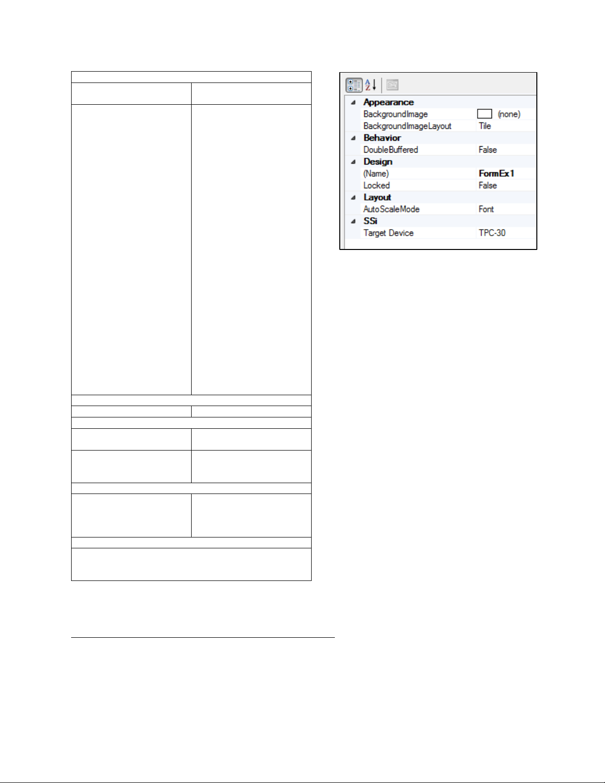
The most common settings to be modified on the Panel are the BackgroundImage (under
Appearance) and the Target Device (under the SSi grouping). The Target Device can be modified
at the Panel level. The Panel size should match the resolution of the target screen, which is
determined by the Target Device selection.
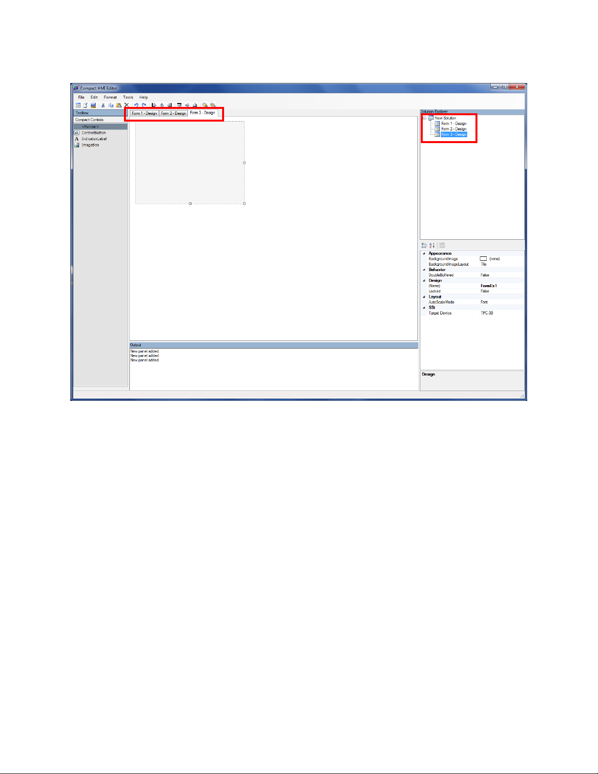
Figure 6 - Compact HMI Editor Design Environment
Page 10
Compact HMI and Compact HMI Editor Operations Manual
Super Systems Inc.
Page 10 of 60
Figure 7 - Design Environment with Panels Added
Figure 7 shows a Design Environment view with multiple Panels. On the bottom right is a view of
the Panel's properties.
NOTE: The first Panel created is called “Main” by default. You may change the name of this
Panel (or any others) as you wish. See
Table 1 for descriptions of Panel properties and an
example properties grid in Figure 8.
Remember that Panels can be arranged in the order in which you want them to appear in
Compact HMI on the touch screen. To reorder Panels, simply click and drag each tab into the
order in which you wish it to appear.
Page 11
Compact HMI and Compact HMI Editor Operations Manual
Super Systems Inc.
Page 11 of 60
Appearance
BackgroundImage
The background image
used for the Panel
BackgroundImageLayout
The layout used for the
otherwise would.
Behavior
DoubleBuffered
Do not change this setting.
Design
(Name)
Identifies the name used in
code to identify the object
Locked
Determines whether the
resized
Layout
AutoScaleMode
Determines how the form
change
SSi
See the “SSi Options” section below.
Table 1 - Panel properties
Figure 8 - Panel properties grid
background image.
Possible settings are:
• None: Image will be
applied with no
changes to its
appearance.
• Tile: Image will be tiled
multiple times in the
background (the
smaller the image's
dimensions, the more
frequently it will
appear)
• Center: The image will
be centered in the
background.
• Stretch: The image will
be stretched to fit the
background area.
• Zoom: The image will
be enlarged within the
background area. Note
that the visible part of
the image will appear
larger than it
SSi Options
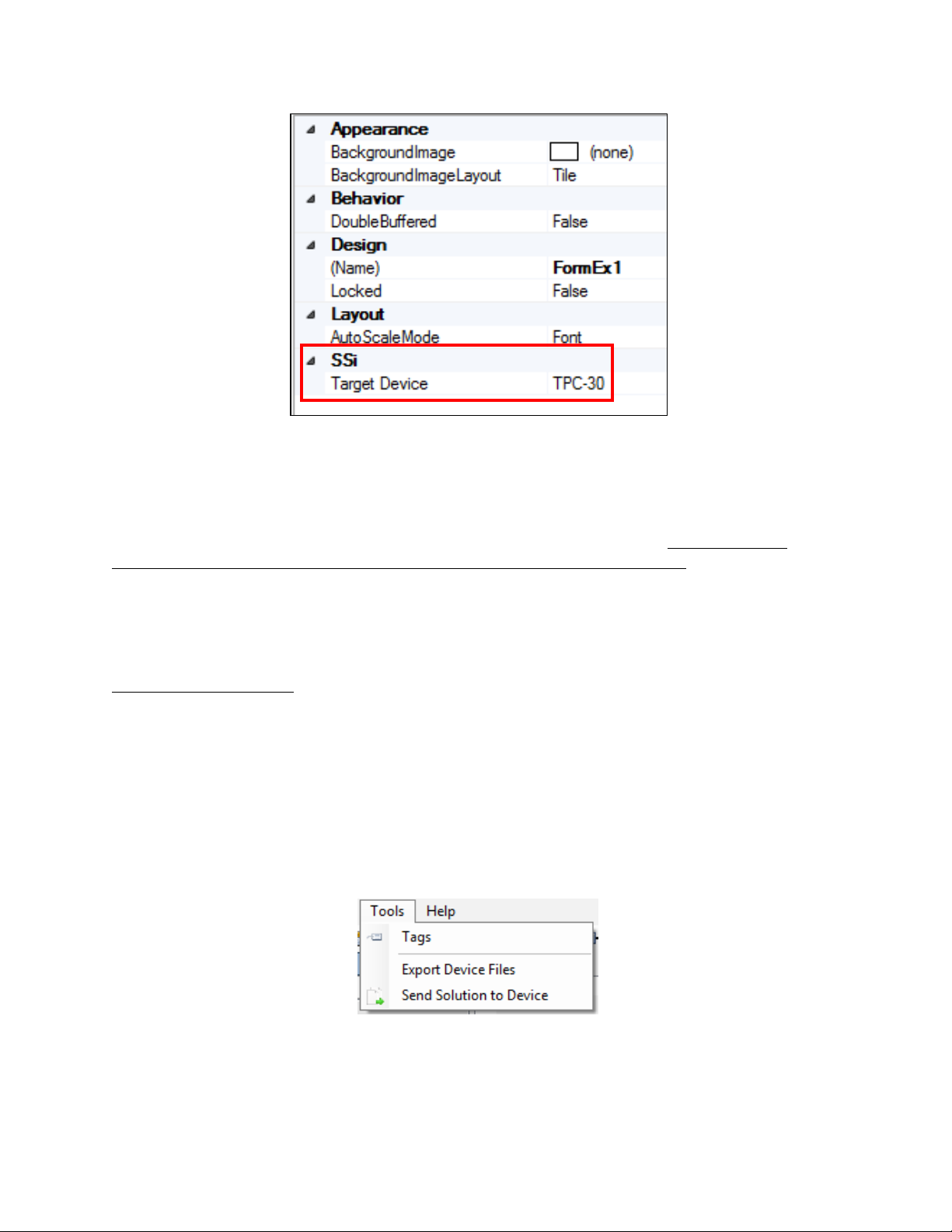
The active panel must be selected for this to be visible. If a control object is currently selected,
for example, the options will not be visible. Figure 9 shows what the options look like in the
Design View.
control can be moved or
or control will scale when
screen resolution or fonts
Page 12
Compact HMI and Compact HMI Editor Operations Manual
Super Systems Inc.
Page 12 of 60
Figure 9 - SSi Options
Target Device: The touch screen device model on which the Compact HMI will be running.
Models can be selected from a drop-down list. Typically, the models will start with “TPC-“ and
end in a number, sometimes followed by one or more letters. If the model starts with “TPC-3,”
the screen size is usually 3.5”. If the model starts with “TPC-6”, the screen size is usually 5.7”.
Finally, if the model starts with “TPC-12”, the screen size is usually 12.1”
This setting will
determine the size of each panel in the Solution and is extremely important. An incorrect
setting will result in the panels being rendered incorrectly—or not being rendered at all—on the
touch screen.
Contact SSi at (513) 772-0060for help with setting up these options.
Tags (Tag Management)
Compact HMI Editor includes a database framework that allows you to associate connections
with tags and tags with register locations. Each connection is identified by a user-defined name
along with relevant connection details. Each tag is associated with a 16-bit word register. All of
the connection, tag, and register data is contained in a “tags database” that Compact HMI
maintains. This approach allows you to configure Compact HMI to access data in a
straightforward and organized fashion.
To access the tags database, click on Tools Tags (Figure 10) in the Compact HMI Editor main
window.
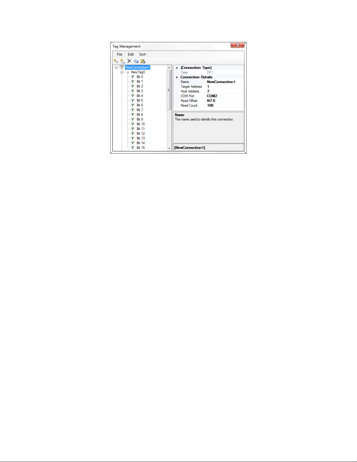
The Tag Management window will appear (Figure 11). In the example screen shot in Figure 11,
the window is populated with connection, tag, and bit data. More information is provided in this
section on how to configure connection, tag, and bit settings.
Figure 10 - Tag Management
Page 13
Compact HMI and Compact HMI Editor Operations Manual
Super Systems Inc.
Page 13 of 60
Figure 11 - Tag Management window
In the Tag Management window, you can perform several actions:
• Create a new connection name and define the connection parameters;
• Create a new tag under a connection name and associate it with a register location;
• Name tags and register bits associated with tags by using specific designations such as
Input, Output
, and
Alarm
;
• Identify bits that are associated with a bit alarm;
• Filter tags by search string (partial strings are okay); and
• Remove existing connections, tags, and bit definitions.
In the Tag Management window, the File menu provides these options: Add Connection, Add
Tag, and Close. Select Add Connection to add a new connection, Add Tag to add a new tag, and
Close to close the Tag Management window.
Page 14
Compact HMI and Compact HMI Editor Operations Manual
Super Systems Inc.
Page 14 of 60
For Allen-Bradley DF1 Connections
SSi 9000 Series controller.
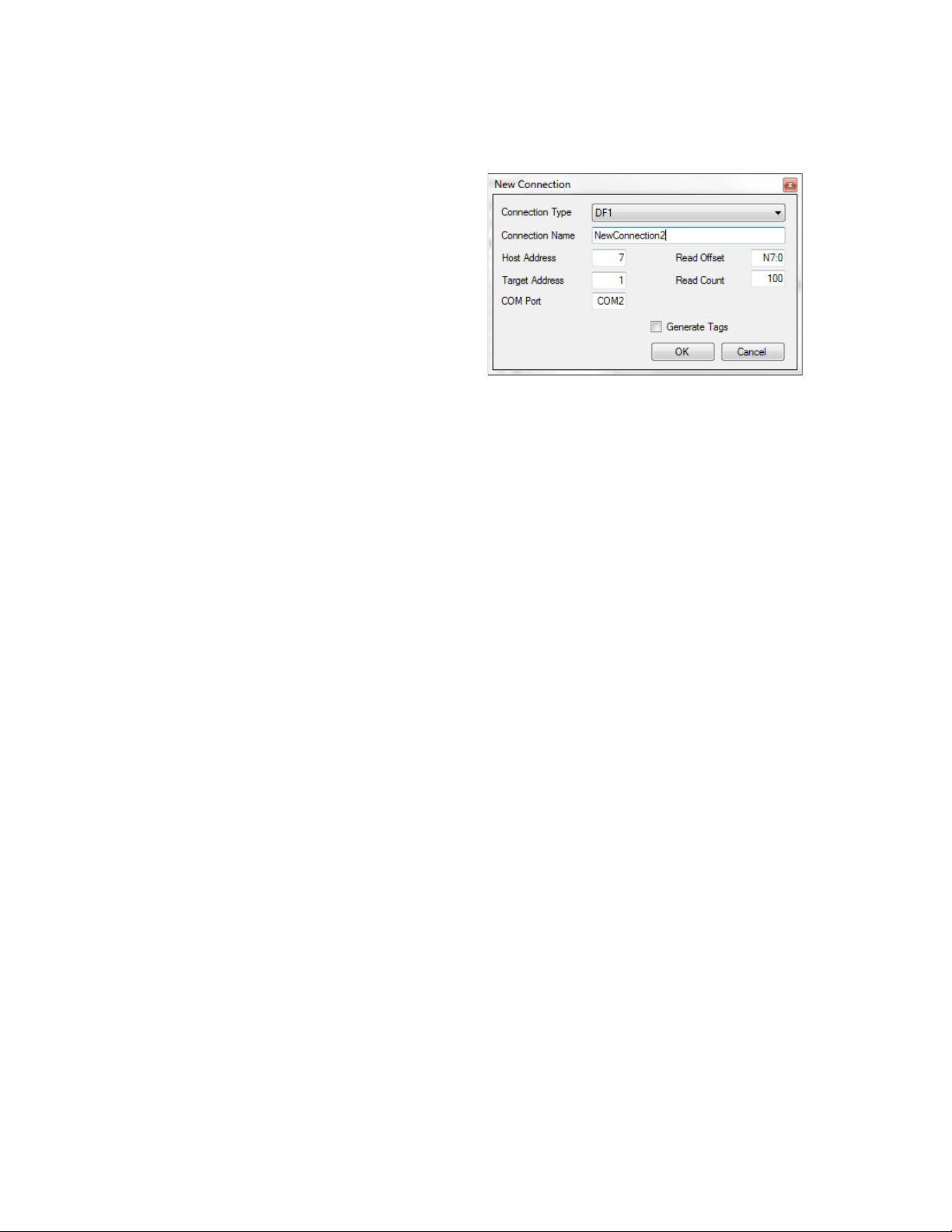
Figure 12 – New Connection window (DF1)
Connection properties are first defined in the New Connection window (Figure 12). The
parameters that must be set are as follows:
(Example: Figure 12)
• Connection Type: The protocol used
for communication between Compact
HMI and the data device. Available
settings are DF1, ModbusRTU, and
ModbusTCP.
• Connection Name: The user-defined
name for the Connection.
Recommended:
Use a Connection
Name that can be easily associated
with the data device and register
locations from which Compact HMI
will be reading and writing data.
• Host Address: The address of the
touch screen. Normally, this setting
can be kept as the default.
• Target Address: The address of the
data device. Normally, this setting can
be kept as the default.
• COM Port: The COM (serial) Port with
which the Compact HMI touch screen
will be connected to the data device.
This must match the actual COM Port
on which the serial cable is connected
to the touch screen.
The default COM Port is COM 2. Some
touch screens may have only one COM
Port. In such a case, COM 1 will need
to be used for the data device
connection, and an Ethernet
connection will need to be used for the
• Read Offset: The register address where
Compact HMI starts reading. This must be
defined to the word level within the data device.
• Read Count: The default number of registers,
starting with the Read Offset, that will be read.
The default is 100. This value must not exceed
the number of registers actually defined within
the data device.
Generate Tags checkbox: When checked, this
checkbox will cause tags to be generated. The tags
generated will be based on the Read Offset and
Read Count defined in this menu. For example,
with default settings, the tags generated will start
“N7:0” and end “N7:99”. Bits will be created for
each tag as well (Bit 0 through Bit 15).
Page 15
Super Systems Inc.
Page 15 of 60
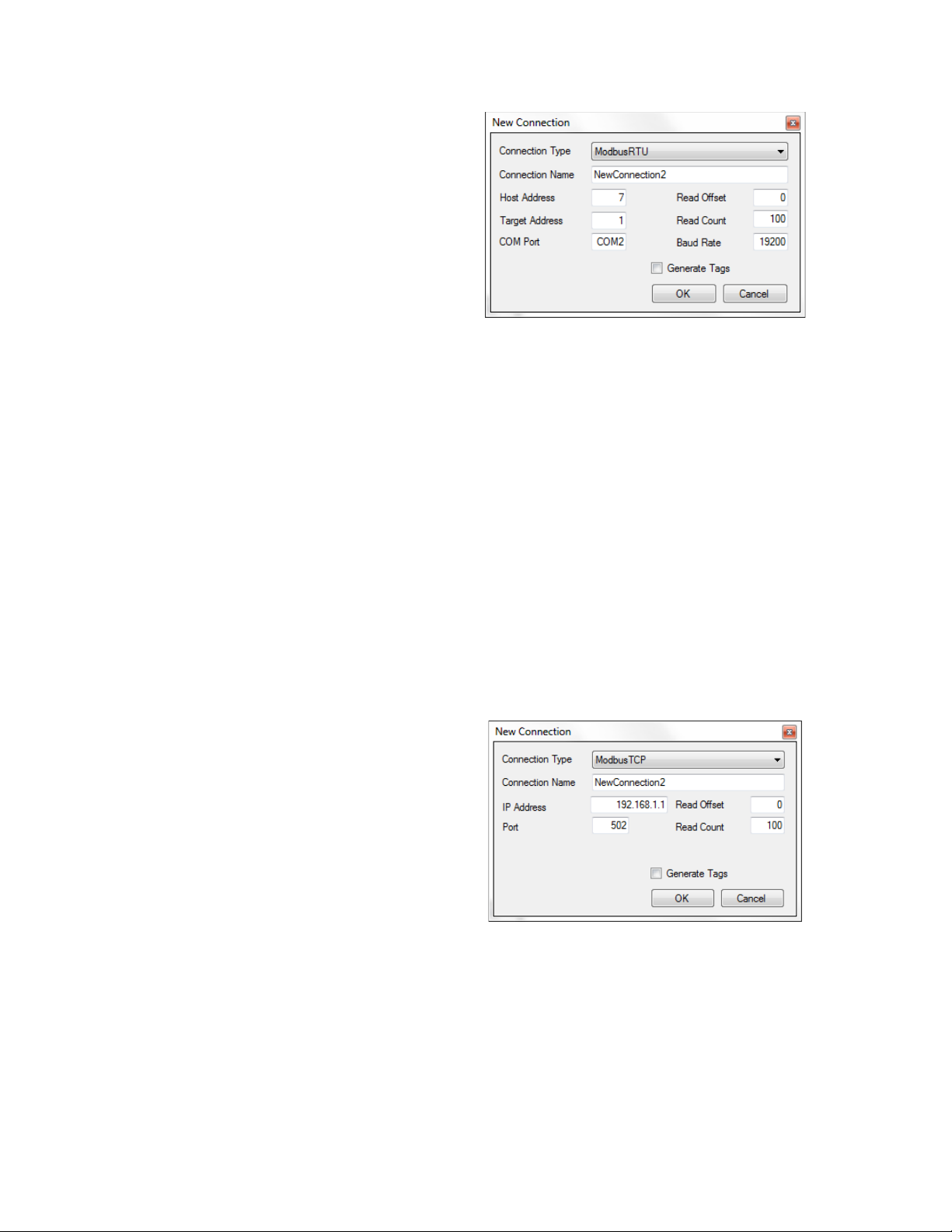
For ModbusRTU Connections
(Example: Figure 13)
Figure 13 – New Connection window (ModbusRTU)
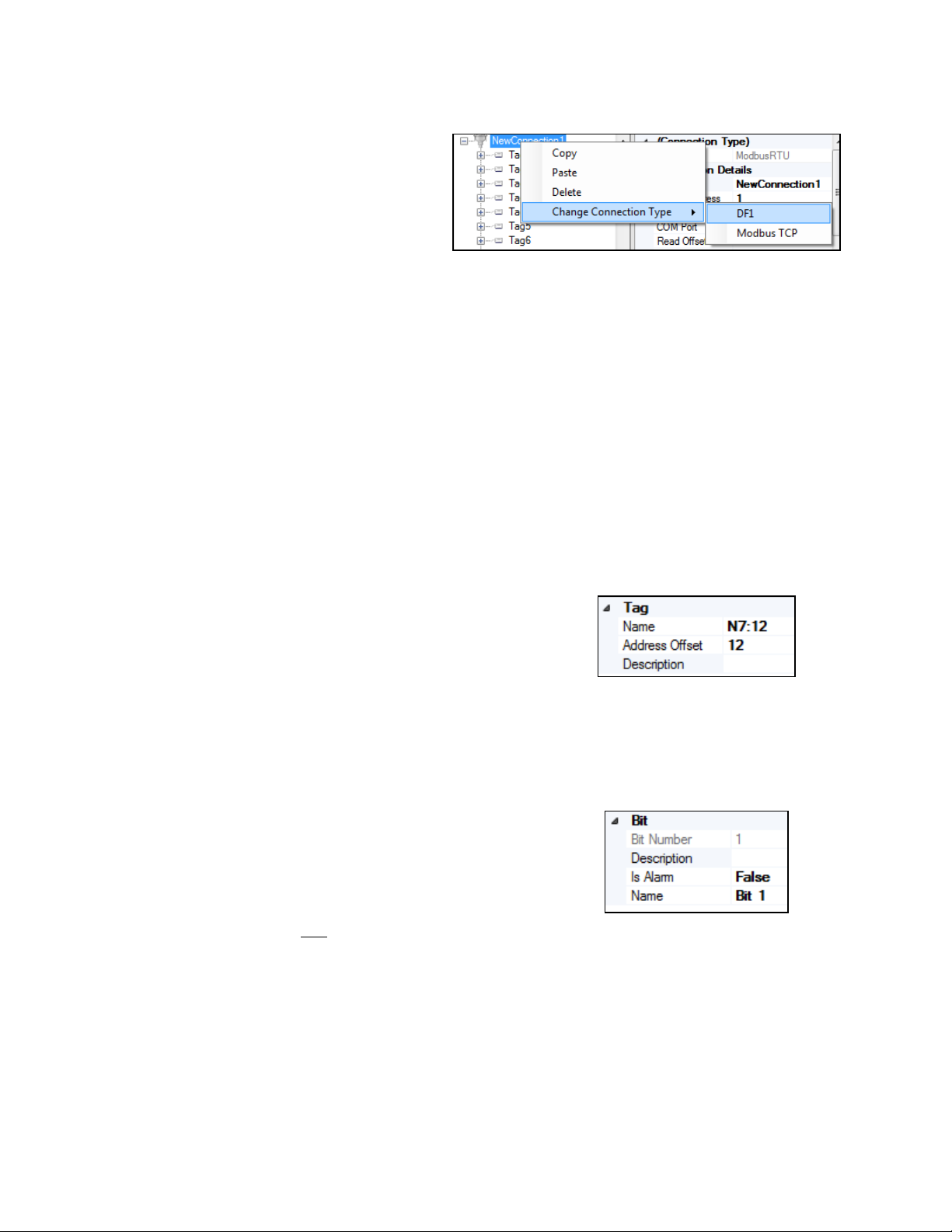
For ModbusTCP Connections
Figure 14 – New Communications Window (ModbusTCP)
named Tag0, Tag1, and so on, through Tag99.
• Host Address: The address of the
touch screen. Normally, this setting
can be kept as the default.
• Target Address: The address of the
data device. Normally, this setting can
be kept as the default.
• COM Port: The COM (serial) Port with
which the Compact HMI touch screen
will be connected to the data device.
This must match the actual COM Port
on which the serial cable is connected
to the touch screen.
The default COM Port is COM 2. Some
touch screens may have only one COM
Port. In such a case, COM 1 will need
to be used for the data device
connection, and an Ethernet
connection will need to be used for the
SSi 9000 Series controller.
• Read Offset: The register address
where Compact HMI starts reading.
This must be defined to the word level
within the data device.
Compact HMI and Compact HMI Editor Operations Manual
• Read Count: The default number of registers,
starting with the Read Offset, that will be read.
The default is 100. This value must not exceed
the number of registers actually defined within
the data device.
• Baud Rate: The rate (in units per second) at
which communications bits are sent between
the touch screen and data device. The default is
19200.
Generate Tags checkbox: When checked, this
checkbox will cause tags to be generated. The tags
generated will be based on the Read Offset and
Read Count defined in this menu. For example, if
the Read Offset is 0 and the Read Count is 100, the
tags generated will be named Tag0, Tag1, and so
on, through Tag99.
(Example: Figure 14)
• IP Address: The IP address of the data
device.
• Port: The port number on the data
device through which the data device
will exchange data.
• Read Offset: The register address
where Compact HMI starts reading.
This must be defined to the word level
within the data device.
• Read Count: The default number of
registers, starting with the Read
Offset, that will be read. The default is
100. This value must not exceed the
number of registers actually defined
within the data device.
• Generate Tags checkbox: When checked, this
checkbox will cause tags to be generated. The
tags generated will be based on the Read
Offset and Read Count defined in this menu.
For example, if the Read Offset is 0 and the
Read Count is 100, the tags generated will be
Page 16
Compact HMI and Compact HMI Editor Operations Manual
Super Systems Inc.
Page 16 of 60
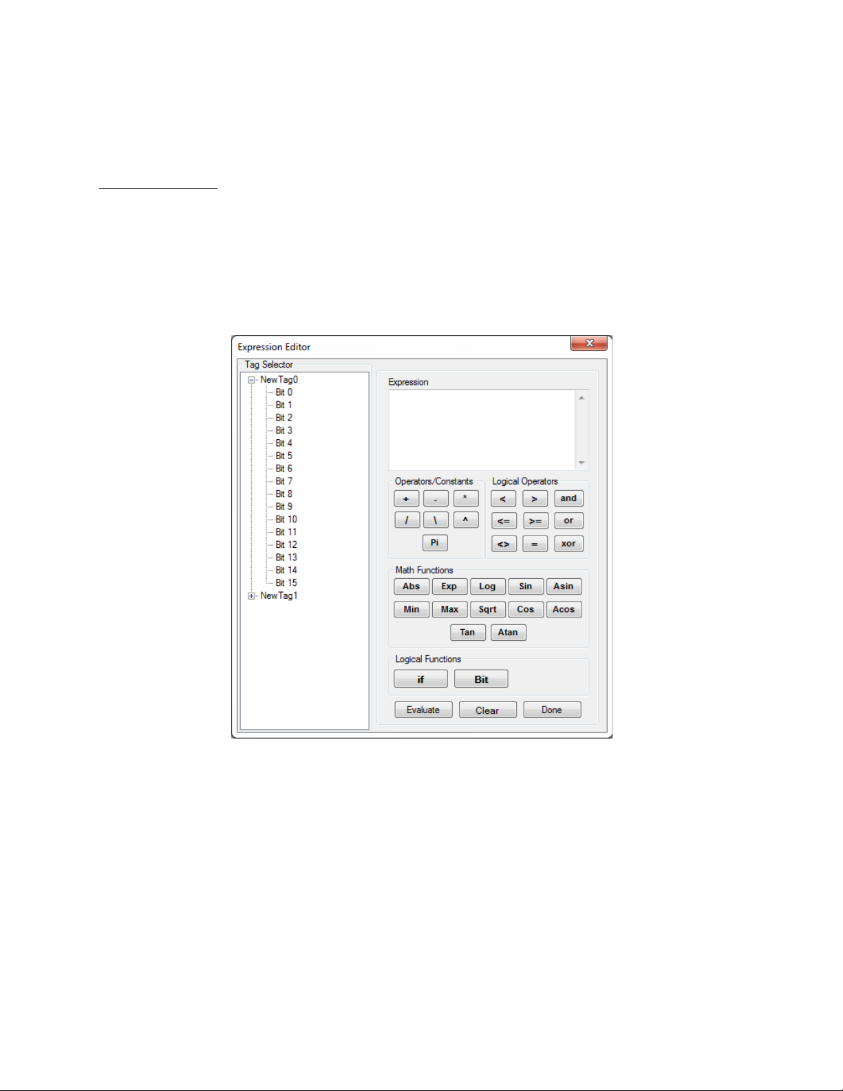
Connection types can be changed after a
Figure 15 - Change Connection Type option
Using the tag properties grid, you can name the tag set
Figure 16 - Tag "Data" fields
Each register is made up of 16 bits. The bits are
This feature is intended for future use.
Figure 17 - Bit fields
connection is defined. To do this, right
click on the Connection Name, select
“Change Connection Type”, and select the
Connection Type desired. See an example
in
Figure 15.
The Edit menu allows you to copy an existing connection or tag with all of its properties and bit
settings. Do this by first selecting the item you want to copy, then click
and then click
“
ItemName –
Finally, using the
Paste in the Edit menu. The new (copied) item will be added to the tags list as
Copy(
number
)”. Using the Edit menu’s Delete option, you can remove an item.
Find & Replace option, you can direct Compact HMI Editor to search for a
Copy in the Edit menu,
specific string of text in tag names and replace that text names with text that you enter.
The Sort menu allows you to order connection names and tags alphabetically (by name) or by
address (in the case of tags, that is the register address associated with the tag). Sorting can be
performed in ascending or descending order.
and address offset, and enter a brief description. See
Figure 16.
The default name of the tag will be “NewTag
x
is a sequential number. The Address Offset will be
applied to the Data Offset previously assigned to the
Panel. For example, referring to Figure 9 and Figure
16, if a Data Offset of N7:0 and Address Offset of 4 are
defined, the actual register being evaluated will be
N7:4.
numbered 0 through 15. Compact HMI Editor allows
you to name each bit, add a brief description, and
identify whether the bit is an alarm bit (see
If “Is Alarm Bit” is set to False, Compact HMI will not
identify the bit as an alarm bit; if “Is Alarm Bit” is set to
True, then Compact HMI will identify the bit as an
alarm bit. The default setting for this field is False.
Once configured, tags are used with Compact HMI’s control objects to help determine display
conditions and other characteristics of a control system.
x”,
where
Figure 17).
Page 17
Compact HMI and Compact HMI Editor Operations Manual
Super Systems Inc.
Page 17 of 60
Please refer to Appendix 1: Software Best Practices, “When Configuring Connections and Tags
in Compact HMI Editor,” for information on best practices for configuring connections and tags
in Compact HMI Editor.
Expression Editor
The Expression Editor is used in conjunction with two Control properties: Display Expression
and Display Conditions. The Expression Editor will be displayed when Display Expression or
Display Conditions is selected (for example, from the Control Properties Grid).
NOTE: Some Display Conditions (described in more detail below) and the Expression Editor
utilize Tags.
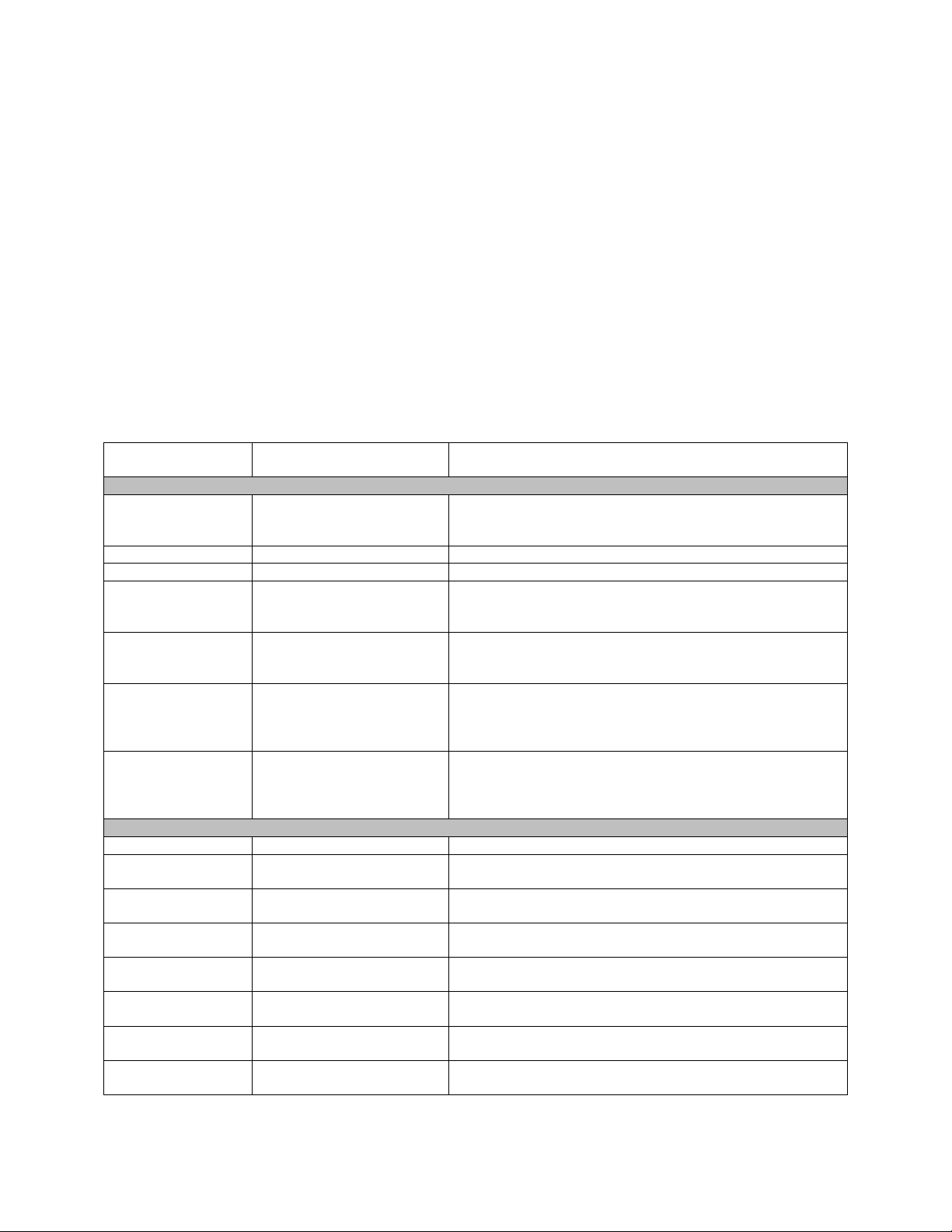
Expression Operators, Constants, and Functions
Tag names identify register locations within a data device. Each register is constituted by a word
containing 16 bits. Compact HMI Editor provides ways of evaluating values contained within data
device registers against values defined by the user. In order to program valid expressions, it is
important to understand the expression syntax used in Compact HMI.
A Tag can be called using the following syntax:
Tag(“[ConnectionName]TagName”) where
connection and
A particular bit can be called according to one of the following two syntaxes:
TagName
Figure 18 - Expression Editor window
ConnectionName
is the name of a defined Tag within that connection.
is the name of a defined
Page 18
Compact HMI and Compact HMI Editor Operations Manual
Super Systems Inc.
Page 18 of 60
Operator/Constant/
Function
Purpose
Examples of Use in Valid Expression
Operators and Constants
+
Performs an addition
Tag(“[Connection1]N7:0”) + 15
- Performs a subtraction
Tag(“[Connection1]N7:0”) - 15
*
Performs a multiplication
Tag(“[Connection1]N7:0”) * 15
/
Performs a division and
(division)
Tag(“[Connection1]N7:0”) / 15
Note: 3/2 returns 1.5
\
Performs a division and
(modulus)
1 / Tag(“[Connection1]N7:1”)
Note: 3\2 returns 1
^
Performs an exponential
Tag(“[Connection1]N7:0”) ^ 3
Pi
Returns the value of Pi,
diameter
Pi + Tag(”[Connection]N7:0”)
Logical Operators
<
Less than
Tag(“[Connection1]N7:0”) < Tag(“[Connection1]N7:1”)
>
Greater than
Tag(“[Connection1]N7:0”) > 1
And
Inclusive of more than one
condition
(Tag(“[Connection1]N7:0”) < 10) and
(Tag(“[Connection1]N7:0”) > 5)
<=
Less than or equal to
Tag(“[Connection1]N7:0”) <= 3
>=
Greater than or equal to
Tag(“[Connection1]N7:0”) >= 3
Or
Inclusive of either/or
condition
(Tag(“[Connection1]N7:0”) < 1) or (Tag(“[Connection1]N7:3”) >
14)
<>
Not equal to
Tag(“[Connection1]N7:0”) <> Tag(“[Connection1]N7:1”)
=
Equal to
Tag(“[Connection1]N7:0.1”) = 0
1. Tag(“[ConnectionName]TagName.BitName”) where
name of a defined Connection,
connection, and
BitName
TagName
is the name of a defined Tag within that
is the name of a defined bit within the register represented by
ConnectionName
is the
TagName.
2. Bit(BitNumber,Tag(“[ConnectionName]TagName”)) where BitNumber is the
number of a bit (0 to 15) within the register represented by
connection
ConnectionName.
TagName
that is part of the
In most cases, Tags and bits will be called for the purpose of:
1. Calculating a value, which will typically be displayed and sometimes scaled before being
displayed; or
2. Evaluating a condition as True or False.
Table 2 provides details on the operators, constants, and functions that can be used in Compact
HMI Editor; the purpose of each; and examples of how they may be used in a valid expression.
keeps the decimal value
drops the decimal value
calculation (calculates a
number raised to a certain
power)
which is the ratio of the
circle’s circumference to its
3^3
Note: Pi by itself returns 3.14159265358979
Page 19

Compact HMI and Compact HMI Editor Operations Manual
Super Systems Inc.
Page 19 of 60
Operator/Constant/
Function
Purpose
Examples of Use in Valid Expression
Xor
Inclusive of one condition,
condition
(Tag(“[Connection1]N7:0”) <= 15) xor
Math Functions
Abs
Absolute value
Abs(Tag(“[Connection1]N7:0”))
Exp
Calculates base e raised to a
Exp(Tag(“[Connection1]N7:0”))
Note: Exp(3) calculates e to the power of 3
Log10
Base 10 logarithm
Log10(Tag(“[Connection1]N7:0”))
Log10(100) returns 2
Sin
Sine (trigonometric)
Sin(Tag(“[Connection1]N7:0”))
Asin
Arcsine or inverse sine
(trigonometric)
Asin(Tag(“[Connection1]N7:0”))
Min
Minimum
Min(Tag(“[Connection1]N7:0”),Tag(“[Connection1]N7:1”),
Tag(“[Connection1]N7:2”),Tag(“[Connection1]N7:3”))
Max
Maximum
Max(Tag(“[Connection1]N7:0”),Tag(“[Connection1]N7:1”),
Tag(“[Connection1]N7:2”),Tag(“[Connection1]N7:3”))
Sqrt
Square root
Sqrt(Tag(“[Connection1]N7:1”))
Cos
Cosine (trigonometric)
Cos(Tag(“[Connection1]N7:1”))
Acos
Arccosine or inverse cosine
(trigonometric)
Acos(Tag(“[Connection1]N7:1”))
Tan
Tangent (trigonometric)
Tan(Tag(“[Connection1]N7:1”))
Atan
Arctangent or inverse
tangent (trigonometric)
Atan(Tag(“[Connection1]N7:1”))
Logical Functions
If
Returns a value of TRUE or
condition is false)
If(Tag(“[Connection1]N7:0”)<Tag(“[Connection1]N7:1”),1,0)
exclusive of a second
specified power
FALSE
Syntax:
If(condition,return_if_true
,return_if_false)
condition is the condition
evaluated,
is the value returned if the
condition is true,
return_if_false is the
value returned if the
, where
return_if_true
(Tag(“[Connection1]N7:0”) = 5)
Note: If(2<3,1,0) returns 1
Table 2 - Expression Operators, Constants, and Functions in Expression Editor
Display Conditions
Display Conditions determine display elements for control objects by using the results of
evaluated expressions. The display conditions are found in the properties grid for controls. You
can also bring up the display conditions by double clicking on the control object for which you
want to set the display conditions.
NOTE: Some Display Conditions and the Expression Editor (described in more detail above)
utilize Tags.
Page 20

Compact HMI and Compact HMI Editor Operations Manual
Super Systems Inc.
Page 20 of 60
Figure 19 - Display Conditions window
Figure 19 shows the base window that appears when Display Conditions are opened. Note the
expanded list of options shown below the (
options from the
File Add Condition menu selection. Both show the categories of display
conditions that can be applied to a control based on evaluations described in “
Add Condition) button. You can also access these
Expression
Editor“. These categories are as follows:
• Background Color affects the background color of the control.
• Position affects the position of the control.
• Size affects the size of the control.
• Text affects the text displayed within the control.
• Text Color affects the color of the text displayed within the control.
• Visibility affects whether the control is visible (true) or not (false).
Once you have added a condition, Compact HMI Editor will create a category for the condition,
as shown in Figure 20. The number of conditions in each category will be the total number of
conditions that have been added to that category. Each condition will have the name of the
category to which the condition applies until you change the condition’s name, as described
below.
Page 21

Compact HMI and Compact HMI Editor Operations Manual
Super Systems Inc.
Page 21 of 60
Figure 20 - Conditions window with conditions added
To change the name of the condition, click on the name of the condition shown in the “Name”
field of the property grid (Figure 21).
Page 22

Compact HMI and Compact HMI Editor Operations Manual
Super Systems Inc.
Page 22 of 60
Figure 21 - Changing condition name
The “Text” field contains the text that will be displayed when the condition is applied.
The “Expression” field determines whether the condition is true or false, in this case. Setting up
an expression is described in “Expression Editor”.
To delete a condition, simply right click on the condition in the list on the left bar, and then click
Delete (Figure 22), or use the “X” ( ) button.
Figure 22 - Delete option
Page 23

Compact HMI and Compact HMI Editor Operations Manual
Super Systems Inc.
Page 23 of 60
How Conditions are Prioritized
Compact HMI will evaluate each condition in a linear order—from top to bottom as each
condition appears in the list of conditions in Compact HMI Editor. To change the priority of a
condition, simply use the arrow buttons ( and ) or right click on the condition whose
priority you want to change and click “Move Up” or “Move Down” as needed.
As conditions are evaluated as true or false, the following rules will be applied:
• When a condition is false, no action will be taken.
• When a condition is true, the action associated with that condition will be implemented.
• When more than one condition in a single category is true, the last condition that is true
will be the condition whose associated action is implemented.
• When all of the conditions in a single category are false, the setting associated with that
category will be set to the default.
Consider the following cases.
Page 24

Compact HMI and Compact HMI Editor Operations Manual
Super Systems Inc.
Page 24 of 60
Case 1: All Conditions Are Evaluated as True
Category
Condition Name
Order of
Evaluation within
Category
Condition
True or False
Result
Background Color
RedBackgroundColor
First
Machine is in alarm
state
True
Background color
implemented
Background Color
BlueBackgroundColor
Second
Machine is running
True
Background color
implemented
Background Color
YellowBackgroundColor
Third
Machine is not
running
True
Background color
implemented
Table 3 - Example of Condition Evaluation (All True)
Case 2: At Least One Condition Is Evaluated as True, the Others as False
The examples below could apply to a number of scenarios. For illustration, assume that Compact HMI controls were developed for a
batch furnace. When designing the HMI, the interface designer wanted to make sure that the control clearly indicates conditions
such as running and alarm states so that the operator is aware of the those states. The following are programmed conditions that
were evaluated as true or false by Compact HMI and how those evaluations affect the actions taken within a condition category on the
control.
In the first example, a control’s background color is changed based on running conditions of the furnace. RedBackgroundColor,
BlueBackgroundColor, and YellowBackgroundColor are true. However, the YellowBackgroundColor action will be the one
implemented and seen by the user; the reason for this is that YellowBackgroundColor occurs after the other two in the list of
conditions. If RedBackgroundColor should take priority over BlueBackgroundColor and YellowBackgroundColor,
RedBackgroundColor should be moved so that it occurs after the other two in the list.
In this example, text displayed in a control changes based on whether an alarm state is present, the furnace is running normally with
no alarms, the furnace is shut down, or the furnace is starting up. In the case of the Text category, AlarmActiveText is true;
therefore, text programmed for the AlarmActiveText condition will be the text shown. Compact HMI Editor evaluated the remaining
Text conditions and found them to be false. Therefore, even though AlarmActiveText occurs first in the Text category, it will still be
Page 25

Compact HMI and Compact HMI Editor Operations Manual
Super Systems Inc.
Page 25 of 60
Category
Condition Name
Order of
Evaluation within
Category
Condition
True or False
Result
Text
AlarmActiveText
First
One or more alarms
are on
True
Alarm text displayed
Text
NormalOpText
Second
Machine is running
with no alarms
False
No change
Text
ShutdownText
Third
Machine is shut down
False
No change
Text
StartupText
Fourth
Machine is starting up
False
No change
Table 4 - Example of Condition Evaluation (At Least One True, Others False)
Case 3: All Conditions Are Evaluated as False
Category
Condition Name
Order of Evaluation
within Category
Condition
True or False
Result
Visibility
HeatModeOff
First
The heating cycle is
not running
False
No change
Visibility
AutoModeOn
Second
The machine is in
adjusted)
False
Control is displayed
Table 5 - Example of Condition Evaluation (All False)
the condition whose text is displayed on the control. This does not change until (A) AlarmActiveText is evaluated as false or (B) one of
the conditions following AlarmActiveText is evaluated as true.
The HMI programmer wants a control to be visible when a heating cycle is running and the user wants to manually control the cycle’s
output; this is the default setting for the control. The HMI programmer set up the control so that the control will not be visible when
either the heating cycle is not running or the furnace is in Auto (non-manual) mode. In this case, the heating cycle is running and the
machine is not in Auto mode. Both conditions in the Visibility category are evaluated as false; therefore, the default action (to display
the control) is taken.
Auto mode (output
cannot be manually
Page 26

Compact HMI and Compact HMI Editor Operations Manual
Super Systems Inc.
Page 26 of 60
Controls
Compact HMI includes multiple control objects available for use in designing Panels. All
controls will have customizable states that can be applied, allowing the user to conditionally
change many of the properties of the controls. These states are described in more detail in the
“Display Conditions” section.
• The Indicator Label is used for creating graphical displays of data. The user can specify
the format in which the data will be displayed.
• The Image Box is used to display an image on the Panel.
• The Control Button is used for controlling the process data. The control button supports
the following actions:
Value, and Open Menu.
Once the control is added to the Panel, you can select the control and edit its properties. All of
the controls use an offset from the base read defined in the Panel object.
Controls are in the Toolbox on the left side of the visual editor. These controls are what you will
use to display data or take action. Adding a Control is as simple as double-clicking the Control
you want to add.
Set Bit, Reset Bit, Toggle Bit, Send Value, Ask User and Send
Page 27

Super Systems Inc.
Page 27 of 60
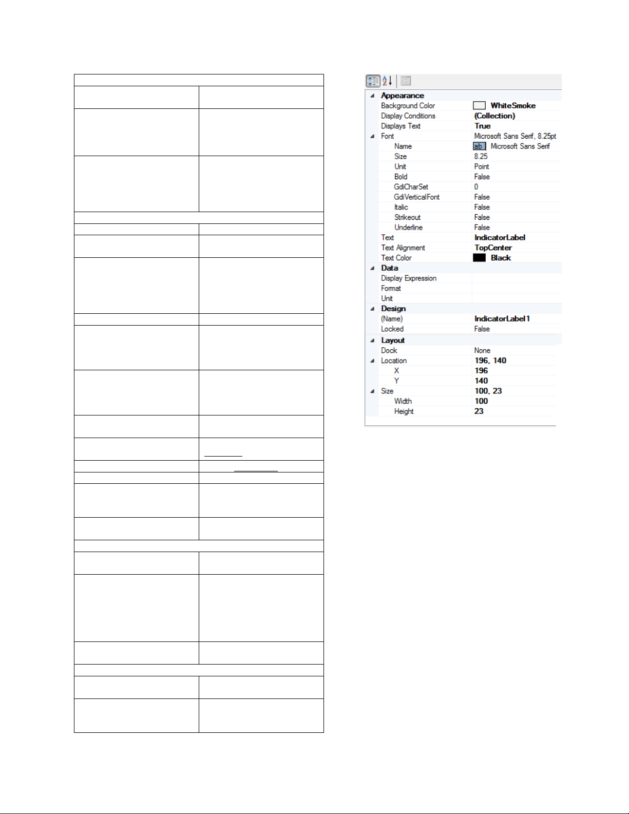
Indicator Label
Compact HMI and Compact HMI Editor Operations Manual
Figure 23 - Indicator Label
The Indicator Label provides a display of data or bit state information to the user. More
specifically, the
Indicator Label has the ability to display static text, conditional text based on an
expression, raw data, or data formatted from an expression. Select the data device tag in the
properties grid at right. Apply a tag from the tags database to the data device tag. See
Table 2
for descriptions of Indicator Label properties and an example properties grid in Figure 24.
Page 28
Compact HMI and Compact HMI Editor Operations Manual
Super Systems Inc.
Page 28 of 60
Appearance
Background Color
The color to display in the
background
Display Conditions
Conditions for changing the
Conditions” section.
Displays Text
If true, label will display the
in the Data group
Font
Name
Name of the font to use
Size
Size of the font, based on
the unit specified in Unit
Unit
The unit on which the size
more information.
Bold
If true, displays text in Bold
GdiCharSet
This setting should not be
Inc.
GdiVerticalFont
This setting should not be
Inc.
Italic
If true, displays text in
Italics
Strikeout
If true, displays text with
Strikeout
Underline
If true, underlines text
Text
The default text to display.
Text Alignment
Aligns text based on one of
settings
Text Color
The color of the displayed
text
Data
Display Expression
The expression that defines
what data is displayed
Format
The format in which to
places.
Units
The units of the displayed
data (°F, for example)
Design
(Name)
Indicates the name used in
code to identify the object
Locked
Determines whether the
resized
Figure 24 - Indicator Label properties grid
way data is displayed. More
details are in the “Display
text in the ‘Text’ field by
default; otherwise, it will
display a data value defined
of the font is based. See
Appendix 2: Font
Measurement Units for
changed without first
contacting Super Systems
changed without first
contacting Super Systems
nine available alignment
display the data. For
example, #.## would
format data with a ones
place and two decimal
control can be moved or
Page 29

Super Systems Inc.
Page 29 of 60
Layout
Dock
Defines which borders of
the container
Location
Coordinates of the upper
left corner of the control.
X
X coordinate of upper left
corner of control
Y
Y coordinate of upper left
corner of control
Size
The size of the control in
pixels.
Width
Width of the control in
pixels
Height
Height of the control in
pixels
Table 6 - Indicator Label properties
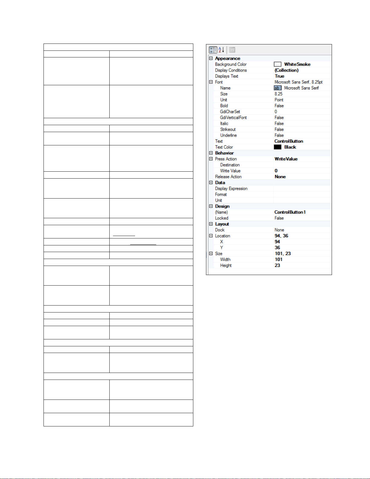
Control Button
Compact HMI and Compact HMI Editor Operations Manual
the control are bound to
The Control Button can display data in exactly the same way as the Indicator Label by
processing the display tag,
but it can also interact with the user and write Control data to the
Figure 25 - Control Button
Page 30

Compact HMI and Compact HMI Editor Operations Manual
Super Systems Inc.
Page 30 of 60
data device based on the Compact HMI configuration. To configure control action, define the
data device tag
controls the behavior of the button. The controls have the following options.
• None is no action.
• SetBit writes a value of “1” to the bit identified in the Target Bit of the Destination
register.
• ResetBit writes a value of “0” to the bit identified in the Target Bit of the Destination
register .
• ToggleBit toggles the bit identified in the Target Bit of the Destination register.
• WriteValue sends the value specified in Write Value to the Destination register.
• AskUserAndWriteValue will present the user with a numeric keypad and will write the
user-provided value to the
• OpenMenu will display a menu that allows the user to navigate between other Panels or
return to the 9000 Series controller screen. It is important that each Panel include a
Control Button with this Action; otherwise, there is no way to navigate away from this
Panel once selected.
• OpenScreen will open the Panel designated in the Screen property
Text in this control object will be centered at the top of the object.
Control Button properties are discussed in Table 7. An example properties grid is shown in
Figure 26.
to write to (also known as the Destination). The Press Action and Release Action
Destination register.
Page 31
Compact HMI and Compact HMI Editor Operations Manual
Super Systems Inc.
Page 31 of 60
Appearance
Background Color
The background color
Display Conditions
Conditions for changing the way
section.
Displays Text
If true, label will display the
the Data group
Font
Name
Name of the font to use
Size
Size of the font, based on the
unit specified in Unit
Unit
The unit on which the size of
more information.
Bold
If true, displays text in Bold
GdiCharSet
This setting should not be
contacting Super Systems Inc.
GdiVerticalFont
This setting should not be
contacting Super Systems Inc.
Italic
If true, displays text in
Italics
Strikeout
If true, displays text with
Strikeout
Underline
If true, underlines text
Text
The default text to display.
Text Color
The color of the displayed text
Behavior
Press Action
The action taken when the
description)
Release Action
The action taken when the
description)
Data
Display Expression
The display tag for the data
Format
The format for the data
Unit
The units of the displayed data
(°F, for example)
Design
(Name)
The name of the control.
Locked
Determines whether the
resized.
Layout
Dock
Defines which borders of the
container
Location
Coordinates of the upper left
corner of the control.
X
X coordinate of upper left
corner of control
Figure 26 - Control Button properties grid
data is displayed. More details
are in the “
text in the ‘Text’ field by
default; otherwise, it will
display a data value defined in
the font is based. See Appendix
2: Font Measurement Units for
changed without first
Display Conditions”
changed without first
button is pressed (see above
button is released (see above
control can be moved or
control are bound to the
Page 32

Super Systems Inc.
Page 32 of 60
Y
Y coordinate of upper left
corner of control
Size
The size of the control in pixels.
Width
Width of the control in pixels
Height
Height of the control in pixels
Table 7 - Control Button properties
Image Box
Compact HMI and Compact HMI Editor Operations Manual
The Image Box is used to display graphics on the panel. It will not be tied directly to data.
However, like all other controls, its properties can be modified through conditional formatting.
Image Box properties are described in
Figure 27 - Image Box
Table 8. An example properties grid is shown in Figure 28.
Page 33

Compact HMI and Compact HMI Editor Operations Manual
Super Systems Inc.
Page 33 of 60
Appearance
Display Conditions
Conditions under which
not displayed.
Image
The image the control
save the Solution.
Transparency Color
The color for the
user).
Design
Name
The name of the control.
Locked
Determines whether the
control can be moved.
Layout
Dock
Determines the position
(alignment) of the image
Location
Coordinates of the upper
left corner of the control.
Size
The size of the control in
pixels.
Table 8 - Image Box properties
Figure 28 - Image Box properties grid
When you are ready to export your Solution to the
Tools Export Device Files
but only use the appropriate Panels at runtime.
Figure 29 - Export Device Files window
the image is displayed or
will display. Compact
HMI Editor will convert
the selected image to a
format Compact HMI
understands and embed
the converted image in
the Solution when you
transparency behind the
image (if chosen by the
Exporting for the Touch Screen
touch screen, select
Figure 29). This option will create a folder containing
all of the Panel and Tag files needed for Compact HMI
on the touch screen. These files are saved to a folder
on your computer, allowing you to transfer the files to
the device manually (by using a flash drive, Compact
Flash card, or other compatible data transfer device),
back up the files, or perform other tasks with them as
necessary. Note that the files saved to the touch
screen device are not the Solution files saved on the
development computer.
The user has the option of saving certain Panels (and
not others) and the runtime executable files (which are
used on the touch screen) when exporting the device
files the specified path. This will allow the user to
create project templates with multiple screen layouts,
(see
Page 34

Compact HMI and Compact HMI Editor Operations Manual
Super Systems Inc.
Page 34 of 60
Please refer to Appendix 1: Software Best Practices, “Backing Up Touch Screen Files (.cfxml
and .tdx)”, for information on best practices for backing up touch screen files.
NOTE: The “Use with Compatible Touch Screens” section contains an example of how these
files are used.
Interacting with the Touch Screen
NOTE: These features have been tested only on the 5.7 inch touch screen using a USB
connection.
Compact HMI Editor can also write the Panels in your Solution directly to the touch screen using
Tools Send Solution to Device when the touch screen is connected via USB using Mobile
Device Center (Windows Vista, 7, & 8) or ActiveSync (Windows XP). Compact HMI Editor will
clear the .cfxml files from the touch screen's CompactRealtime folder and save the Panels in
the Solution to the touch screen.
Please refer to Appendix 1: Software Best Practices, “Backing Up Touch Screen Files (.cfxml
and .tdx)”, for information on best practices for backing up touch screen files.
Using the Main Menu
The Main Menu in Compact HMI Editor is comprised of five option headings, as shown in Figure
30. The option headings are File, Edit, Format, Tools, and Help. This section describes each of
the options under each option heading.
File
Figure 30 - Main Menu Bar
Figure 31 - File menu
Page 35

Compact HMI and Compact HMI Editor Operations Manual
Super Systems Inc.
Page 35 of 60
The File menu contains the following options:
• New is used to create a new Panel or a new Solution. New Panels can also be created in
the Solution Explorer. If a new Solution (a collection of Panels) is created and the
current Solution has not been saved, Compact HMI Editor will prompt the user with the
option to save the current Solution before opening a new one.
• Open Solution allows you to open a saved Solution (.cresln) file.
• Close Solution allows you to close the currently open Solution. If the Solution has not
been saved, you will be prompted with the option to save the current Solution.
• Save saves the current Solution.
• Save As saves the current Solution with a new file name.
• Recent Solutions will bring up a list of Solutions that were recently open in Compact HMI
Editor.
• Exit exits the program. If the current Solution has not been saved, Compact HMI Editor
will prompt the user with the option to save the current Solution before opening a new
one.
Please refer to Appendix 1: Software Best Practices, “When Saving Multiple Solutions” and
“Backing Up Development Files,” for information on best practices for saving and backing up
developments files in Compact HMI Editor.
Edit
Figure 32 - Edit menu
The Edit menu contains the standard Windows editing options.
• Undo will reverse the previous action performed in Compact HMI Editor.
• Redo will repeat a previously reversed action.
• Cut will remove a selected component and save it to the Clipboard.
• Copy will copy a selected component to the Clipboard so that it can be duplicated.
• Paste will place the content most recently copied to the Clipboard in the active window
or field.
• Delete will remove the selected component without copying it to the Clipboard.
• Select All will select all of the components that can be selected in the active window or
field.
Page 36

Super Systems Inc.
Page 36 of 60
Format
Compact HMI and Compact HMI Editor Operations Manual
Figure 33 - Format menu
The Format menu contains the following options:
• Align contains options to change the alignment of multiple objects.
o
Align Lefts
o
Align Centers
are aligned
o
Align Rights
o
Align Tops
o
Align Middles
aligned
o
Align Bottoms
aligned
• Make Same Size contains options to make the width, height, or both width and height of
multiple selected objects the same.
• Horizontal Spacing contains options to increase, decrease, or equalize the horizontal
spacing between multiple selected objects.
• Vertical Spacing contains options to increase, decrease, or equalize the vertical spacing
between multiple selected objects.
• Center in Form allows you to center the selected controls within the form horizontally or
vertically.
• Order allows you to arrange a selected object so that it appears in front of other objects
that overlap it (Bring to Front) or so that it appears behind other objects that overlap it
(Send to Back).
moves multiple selected objects so that their left edges are aligned
moves multiple selected objects so that their horizontal centers
moves multiple selected objects so that their right edges are aligned
moves multiple selected objects so that their top edges are aligned
moves multiple selected objects so that their vertical middles are
moves multiple selected objects so that their bottom edges are
Tools
Figure 34 - Tools menu
Page 37

Compact HMI and Compact HMI Editor Operations Manual
Super Systems Inc.
Page 37 of 60
The Tools menu contains the following options:
• Tags will bring up the Tags window. See Tags (Tag Management) for more information.
• Export Device Files exports the files that would normally be saved to the touch screen
device. See
Exporting for the Touch Screen for more details.
• Send Solution to Device will send the current Solution to a connected device so that the
device can utilize the programmed screens. See
Interacting with the Touch Screen for
more details.
Help
The Help menu (Figure 35) contains three options: About, Language, and Check for Updates….
Figure 35 - Help menu
Selecting About will bring up the “About” window, which will show version information on the
software. See
Figure 36 for an example.
Figure 36 - About screen (example)
Selecting Language allows you to set the language in which Compact HMI operates: English or
Spanish (Español). See
Figure 37.
Selecting Check for Updates… will direct CompactHMI Editor to check for updates to the
software and to the executable files that run on the touch screen. An Internet connection from
the PC is required in order to do this.
updates. Failure to do so will result in work being lost since the previous save.
Figure 37 - Language option
IMPORTANT: Save all open files before checking for
Page 38

Compact HMI and Compact HMI Editor Operations Manual
Super Systems Inc.
Page 38 of 60
If an update is found:
If no updates are found:
CompactHMI Editor will prompt you on whether
Figure 38 - Download Updates prompt
Figure 39 - Update status window
CompactHMI Editor will present a window
Figure 40 - "No Updates Available" window
you want to download the updates (Yes) or not
(No)—see
Figure 38.
If you click “Yes”, the software will close; updates
will be downloaded and then installed. A status
window will appear while the updates are being
downloaded and installed (Figure 39).
indicating that no updates are available
(
Figure 40).
Once the updates are installed, CompactHMI Editor will restart.
Touch Screen Files: Automatic Updates include files that will be needed for Compact HMI on the
touch screen. In order to copy updated touch screen files to the touch screen, follow the
procedure below.
1. Locate the TouchScreen subfolder in the folder where Compact HMI Editor is located. An
example is shown in
Figure 41 (where the subfolder is
“C:\SSi\Bin\CompactHMI\TouchScreen”).
Figure 41 - TouchScreen folder (for updated touch screen files)
Page 39

Compact HMI and Compact HMI Editor Operations Manual
Super Systems Inc.
Page 39 of 60
2. Insert a USB drive into a USB port on the computer.
3. Copy the files from the “TouchScreen” subfolder to the USB drive.
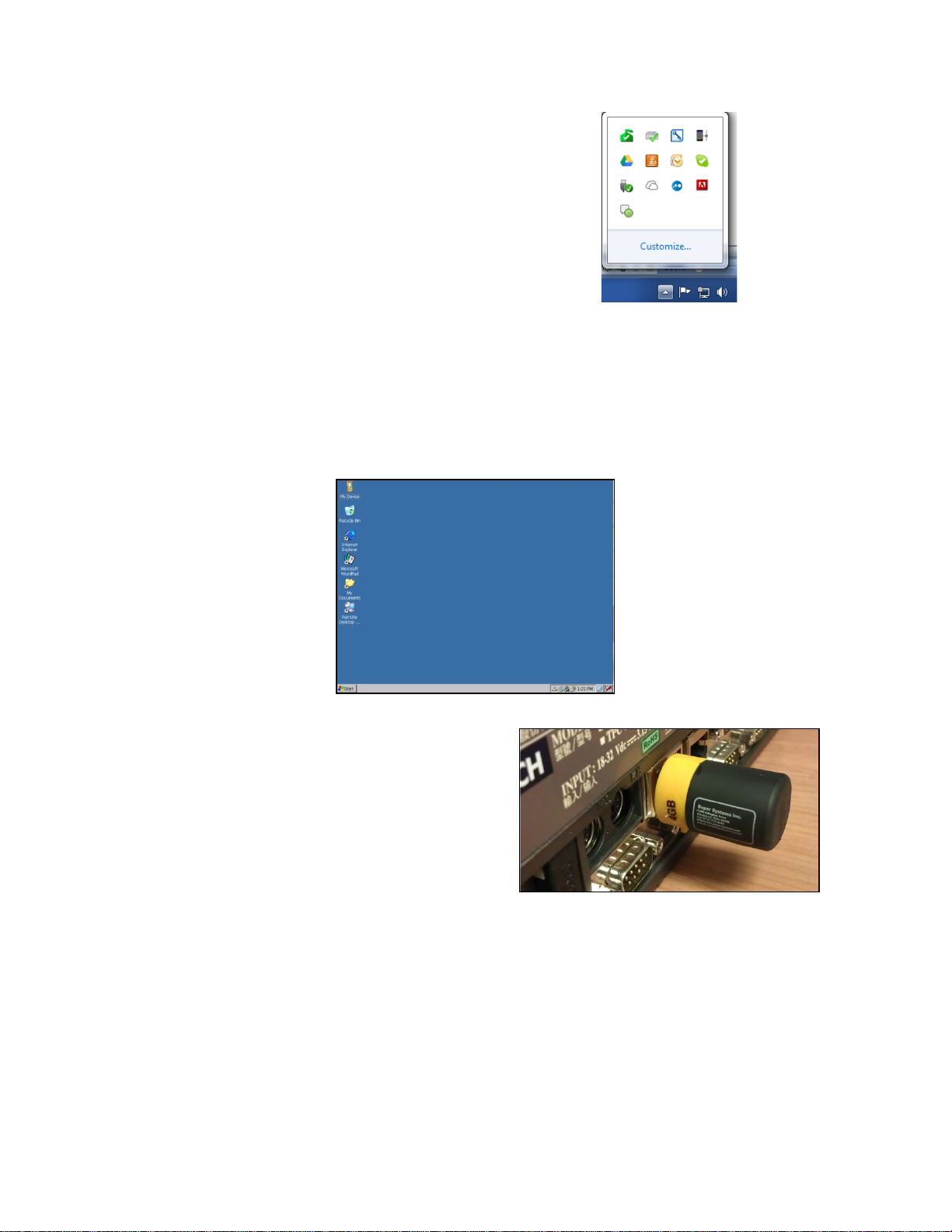
4. Remove the USB drive by selecting “Eject Mass Storage” from the System Tray options
(Figure 42) and then taking the flash drive out of the USB port. If an error appears, make
sure that all files have finished copying and that any windows showing the USB drive or
its contents have been closed.
Figure 42 - "Eject Mass Storage" option
5. With the touch screen on, exit the SSi controller application if it is open. (Refer to the
controller manual or contact SSi at (513) 772-0060 if you have questions about how to do
this.) The operating system screen will appear once the controller application is shut
down. It will look similar to the screen pictured in Figure 43.
Figure 43 - Touch Screen Operating System Screen
Page 40

Compact HMI and Compact HMI Editor Operations Manual
Super Systems Inc.
Page 40 of 60
6. Insert the storage medium into an
Figure 44 - Inserting USB Drive into USB Port on
Touch Screen Device
1 2 3 4 5 6 7 8 9
10
11
12
13
14
15
16
17
18
19
Tool Name
Description
1
New Panel
Opens a new panel for the current Solution, displaying the
2
Brings up a dialog box to open a saved Solution (a file saved by
Solution Overview)
3
Save
Saves the current Solution
4
Removes a block of text, a control object, or other editable
Clipboard so that it can be pasted elsewhere
available USB port on the touch screen.
Often, a port can be found on the back of
the touch screen, as shown in
Figure 44.
7. Double-tap on “My Device” on the touch screen desktop. Then copy the touch screen
files from the USB drive to the Compact HMI (destination) folder. The destination folder
will be the \CompactRealtime folder on the destination drive.
NOTE: A message will likely appear asking if you want to overwrite existing files. Simply choose
“Yes.”
Using the Design Environment Toolbar
The Design Environment contains a horizontal toolbar with icons representing many of the
common options used in Compact HMI Editor. See Figure 45.
The table describes the use of each tool in the toolbar.
Open Solution
Cut
Figure 45 – Toolbar
new panel in the Design Environment
Compact HMI Editor with the .cresln extension; described
further in
component of a Solution, and saves it to the Windows
Page 41

Compact HMI and Compact HMI Editor Operations Manual
Super Systems Inc.
Page 41 of 60
Tool Name
Description
5
Copies a block of text, a control object, or other editable
Clipboard so that it can be pasted elsewhere
6
Places a block of text, a control object, or other editable
Environment component (i.e., Panel)
7
Removes a block of text, a control object, or other editable
component to the Windows Clipboard
8
Undo
Reverses the previous action
9
Redo
Performs an action that was previously reversed
NOTE: All of the “align” options (10 through 15 below) align objects relative to a particular point
they are selected with a mouse.
10
Align Lefts
Moves multiple selected objects so that their left edges are
11
Moves multiple selected objects so that their horizontal
12
Align Rights
Moves multiple selected objects so that their right edges are
aligned
13
Align Tops
Moves multiple selected objects so that their top edges are
aligned
14
Moves multiple selected objects so that their vertical middles
are aligned
15
Moves multiple selected objects so that their bottom edges
are aligned
Copy
Paste
Delete
or axis. For example, Align Lefts will align selected objects so that they share the same left
alignment axis, while Align Middles will align selected objects so that they share the same
vertical middle. Multiple objects are selected by pressing Ctrl+Left Click or Shift+Left Click as
component of a Solution, and saves it to the Windows
component of a Solution in an active field or Design
component of a Solution, but does not save the removed
Align Centers
Align Middles
Align Bottoms
aligned
centers are aligned
Page 42

Compact HMI and Compact HMI Editor Operations Manual
Super Systems Inc.
Page 42 of 60
Tool Name
Description
16
Bring to Front
Arranges a selected object so that it appears in front of other
objects that overlap it
17
Send to Back
Arranges a selected object so that it appears behind other
objects that overlap it
Table 9 - Tools in the Toolbar and Their Use
Page 43

Compact HMI and Compact HMI Editor Operations Manual
Super Systems Inc.
Page 43 of 60
Compact HMI (Use on SSi Touch Screen)
Prerequisites and Installation
An SSi touch screen is required. In order to run Compact HMI Solutions, the SSi touch screen
must be Compact HMI-aware (programmed to recognize Compact HMI Solutions).
SSi designs, customizes, and implements Compact HMI for each touch screen.
Use with Compatible Touch Screens
Compact HMI runs on the touch screen in the \CompactRealtime folder. The \CompactRealtime
folder should have the following file types present:
• .cfxml. Each .cfxml file contains the data for a Panel within the Solution. There will be as
many .cfxml files as there are Panels in the Solution.
• .tdx. The .tdx file is the tags database file. This contains the data for the tags that have
been set up in the Solution.
• .dll. DLL files are required in order for Compact HMI to run properly on the touch
screen.
• .exe. The .exe file is an executable file that is run when Compact HMI is started.
There is no additional configuration necessary other than getting a copy of your primary touch
screen interface that supports Compact HMI; your primary touch screen interface will handle
starting, stopping and interacting with the Compact HMI application for you.
When your Compact HMI-aware interface is handling your Compact HMI Solution, the Menu
button will not take you directly to the Menu. Instead, it will give you the option of going to the
Menu or going to the Compact HMI Solution.
Example of Compact HMI Touch Screen Application Design and Rendering
Once a solution is designed in Compact HMI Editor and saved to a Compact HMI-aware SSi
touch screen, the interface can be accessed through Compact HMI. This section illustrates
examples of Panels that can be set up as part of a solution in Compact HMI in a furnace control
system and how those Panels can be saved from Compact HMI Editor and subsequently opened
in a Compact HMI-aware touch screen as a Compact HMI application.
Example Designs
In this example, a designer has created four Panels for a furnace control system. These Panels
are as follows:
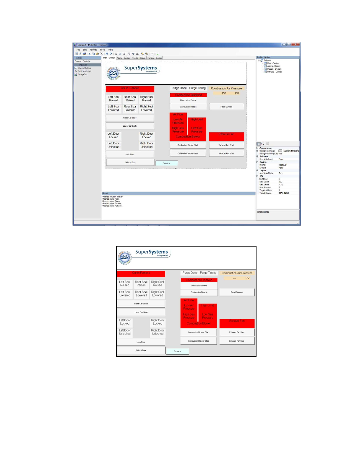
• Main Panel. The Main Panel provides an overview of essential furnace statuses (such as
combustion status and high/low gas pressure alarms) and allows for control of essential
furnace functions (such as locking and unlocking the furnace door). This is the Panel that
will appear when the Compact HMI application is first opened on a compatible touch screen.
The Compact HMI Editor view is shown in
is shown in Figure 47
.
Figure 46; the Compact HMI (Touch Screen) view
Page 44
Compact HMI and Compact HMI Editor Operations Manual
Super Systems Inc.
Page 44 of 60
Figure 46 - Main Panel (Compact HMI Editor)
Figure 47 - Main Panel (Compact HMI - Touch Screen)
Note the Screens button at the bottom of the Panel. Each Panel has one of these buttons. When
pressed, the button will bring up a menu allowing the user to select one of the other panels or
to open the controller touch screen main menu. See the example in
programmed into the panel using the
OpenMenu option as part of the Control Button in
Compact HMI Editor (more information on this can be found in the “
Figure 48. This menu is
Control Button” section).
Page 45

Compact HMI and Compact HMI Editor Operations Manual
Super Systems Inc.
Page 45 of 60
Remember that Panels can be arranged in the order in which you want them to appear in
Compact HMI on the touch screen. To reorder Panels, simply click and drag each tab into the
order in which you wish it to appear.
Figure 48 - Screens menu (Compact HMI - Touch Screen)
• Alarms Panel. The Alarms Panel shows alarms that have been configured in the system. If
an alarm is active, typically the attributes of the alarm display will be programmed to
change (for example, color and visibility). In the example, inactive alarms are displayed in
black text. If an alarm is active, the operator will be able to acknowledge it or take the
appropriate action to correct the alarm condition. The Compact HMI Editor view for the
Alarms Panel is shown in
Figure 49; the Compact HMI (Touch Screen) view is shown in
Figure 50.
Page 46

Compact HMI and Compact HMI Editor Operations Manual
Super Systems Inc.
Page 46 of 60
Figure 49 - Alarms Panel (Compact HMI Editor)
Figure 50 - Alarms Panel (Compact HMI - Touch Screen)
• Presets Panel. In the example, this Panel is used to enter furnace control presets. The
Panel also displays setpoints and process variables (PVs) for parameters such as
combustion air pressure. The Compact HMI Editor view for this Panel is shown in
Figure 51;
the Compact HMI (Touch Screen) view is shown in Figure 52.
Page 47

Compact HMI and Compact HMI Editor Operations Manual
Super Systems Inc.
Page 47 of 60
Figure 51 - Presets Panel (Compact HMI Editor)
Figure 52 - Presets Panel(Compact HMI - Touch Screen)
• Furnace Panel. The Furnace Panel provides furnace status information and allows the
operator to control operations such as starting fans, locking and unlocking doors, etc. A
visualization depicts the status of the furnace in real time. The Compact HMI Editor view for
Page 48

Compact HMI and Compact HMI Editor Operations Manual
Super Systems Inc.
Page 48 of 60
this Panel is shown in Figure 53; the Compact HMI (Touch Screen) view is shown in Figure
54.
Figure 53 - Furnace Panel (Compact HMI Editor)
Figure 54 - Furnace Panel (Compact HMI - Touch Screen)
Page 49

Compact HMI and Compact HMI Editor Operations Manual
Super Systems Inc.
Page 49 of 60
Preparing Solution for Touch Screen
There are two main ways to prepare the Solution to be run on the SSi touch screen:
1. Sending the Solution from Compact HMI Editor directly to the touch screen device; and
2. Exporting the device files to a storage device and copying the device files to the
CompactRealtime on the touch screen’s storage medium.
These methods are described in more detail in the Exporting for the Touch Screen and
Interacting with the Touch Screen sections.
Once the designer has verified that all of the Panels have been set up properly, the designer can
prepare the Solution for use on an SSi touch screen. (The Solution can also be implemented on
the touch screen for testing purposes, when needed.)
Suppose the designer decides to utilize method #2 (exporting and copying the device files to the
touch screen’s storage medium). The designer follows these steps:
1. Save Solution in Compact HMI Editor (using File Save or File Save As).
2. Using the Tools Export Device Files option, export the device files to a USB drive or
other storage medium. This process is depicted in
Figure 55.
Figure 55 - Exporting Device Files
Page 50
Compact HMI and Compact HMI Editor Operations Manual
Super Systems Inc.
Page 50 of 60
3. Once the files are successfully exported,
Figure 56 – “Safely Remove Hardware” icon
6. Insert the storage medium into an
Figure 58 - Inserting USB Drive into USB Port on
Touch Screen Device
eject the storage medium by using the
“Safely remove hardware” option in
Windows (typically found by expanding
the system tray and selecting the
“remove hardware” icon, an example of
which is shown in
Figure 56).
4. Turn on the touch screen.
5. Once the touch screen is on and the startup has completed, exit the SSi controller
application. (Refer to the controller manual or contact SSi at (513) 772-0060 if you have
questions about how to do this.) The operating system screen will appear once the
controller application is shut down. It will look similar to the screen pictured in Figure
57.
Figure 57 - Touch Screen Operating System Screen
available USB port on the touch screen.
Often, a port can be found on the back of
the touch screen, as shown in
NOTE: SSi recommends that you back up touch screen files onto a USB drive or other
storage medium before overwriting those files (which is part of the procedure described
in Step
7). Touch screen files are the .cfxml and .tdx files contained in the
\CompactRealtime folder. If your organization has a backup system in place, these files
should be backed up using that system.
Figure 58.
Page 51

Compact HMI and Compact HMI Editor Operations Manual
Super Systems Inc.
Page 51 of 60
7. Double-tap on My Device on the touch screen desktop. Remove any .cfxml and .tdx files
from the \CompactRealtime folder. Then copy the device files from the storage medium
to the drive from which the touch screen runs Compact HMI (this is typically the drive
from which the touch screen runs the SSi controller application). The destination folder
will be the \CompactRealtime folder on the destination drive. An example of this
procedure is depicted in
Figure 59.
The Solution should now be ready.
Running the Compact HMI Solution
Once the designer has set up the Solution to be run on the touch screen, the designer restarts
the touch screen to load the SSi controller application. When started, each SSi controller touch
screen has a standard screen that will first be displayed. As explained in the “Use with
Compatible Touch Screens” section, if the touch screen is Compact HMI-aware and has
Compact HMI screens saved to the proper location on the storage card, a menu like the one
shown in Figure 60 will be displayed on the standard screen.
Figure 59 - Copying Device Files to CompactRealtime Folder
Page 52

Compact HMI and Compact HMI Editor Operations Manual
Super Systems Inc.
Page 52 of 60
Figure 60 - Compact HMI Menu on Example Screen
Selecting Compact HMI will cause the touch screen software to open the Compact HMI
application.
Page 53

Compact HMI and Compact HMI Editor Operations Manual
Super Systems Inc.
Page 53 of 60
Rev.
Description
Date
MCO #
New
Initial release
10/22/2013
2127
A
Added Modbus communications capabilities
3.5” screen/Compact HMI wiring diagram
4/30/2014
2137
Revision History
as well as program menu changes; added
Page 54

Compact HMI and Compact HMI Editor Operations Manual
Super Systems Inc.
Page 54 of 60
Appendix 1: Software Best Practices
This appendix is intended to provide guidelines for setting up and using the Compact HMI
platform. SSi recommends observing these guidelines, as they have been found to enhance the
usability and functionality of the software.
When Configuring Connections and Tags in Compact HMI Editor
When configuring Connections and Tags, the following principles should be followed:
• Make sure that the Connection Type (DF1, ModbusRTU, or ModbusTCP) is configured
correctly, preferably before tags are added and named.
• Make sure that the Data Offsets are configured correctly. Remember that the Data
Offset must be set individually for each Tag.
• Make sure that the Connection Name is easily associated with the connection to the data
device.
• Make sure that each Tag Name allows for easy identification of a Tag’s register location.
However, avoid making a Tag Name so specific that it could create confusion. For
example, a tag name of “N7:1” would allow for easy identification of the Tag’s register
location (provided that the Data Offset and Address Offset are configured correctly). On
the other hand, a tag name of “Motor A On” could create confusion if the Data Offset
does not align with the correct register.
Relevant Section: “Tags (Tag Management)”, page 12
Backing Up Touch Screen Files (.cfxml and .tdx)
SSi recommends that you back up touch screen files onto a USB drive or other storage medium.
Touch screen files are the .cfxml and .tdx files contained in the \CompactRealtime folder. If your
organization has a backup system in place, these files should be backed up using that system.
Relevant Sections: “Exporting for the Touch Screen,” page 33; “Interacting with the Touch
Screen,” page 34
When Saving Multiple Solutions
When creating multiple Solutions, it is important to maintain a meaningful sub-folder hierarchy.
This hierarchy will assist with differentiating between multiple Solutions, as well as
errant Panels from being transferred to the touch screen. The following suggestion will become
more apparent as you progress through
has been created for
C:
SSi:
Bin:
CompactHMI:
FURNACE #1
FURNACE #1. The following hierarchy is recommended:
this manual. As an example, let’s assume a Solution
prevent
Page 55

Compact HMI and Compact HMI Editor Operations Manual
Super Systems Inc.
Page 55 of 60
In the above example, the User must create the FURNACE #1 sub-folder. The Solution files will
be saved in that folder and include the .cresln, .tdx and .xml files.
Relevant Section: “Using the Main Menu” “File,” page 34
Backing Up Development Files
SSi recommends that you back up development files onto a USB drive or other storage medium.
If your organization has a backup system in place, these files should be backed up using that
system.
Relevant Section: “Using the Main Menu” “File,” page 34
Page 56

Compact HMI and Compact HMI Editor Operations Manual
Super Systems Inc.
Page 56 of 60
Unit Type
Description
World
Specifies the world coordinate system unit as the unit of measure.
Pixel
Specifies a device pixel as the unit of measure.
Point
Specifies a printer's point (1/72 inch) as the unit of measure.
Inch
Specifies the inch as the unit of measure.
Document
Specifies the document unit (1/300 inch) as the unit of measure.
Millimeter
Specifies the millimeter as the unit of measure.
Appendix 2: Font Measurement Units
The following are font measurement units used in determining how fonts are sized.
Source: Microsoft Developer Network.
Page 57

Compact HMI and Compact HMI Editor Operations Manual
Super Systems Inc.
Page 57 of 60
Appendix 3: Typical Wiring Diagrams
This appendix contains typical wiring diagrams for Compact HMI-configured touch screens in the 3.5”, 5.7”, and 12.1” sizes that are
connected to a compatible data device and 9000 Series controller. Different touch screens may require different connection methods based
on their configuration. Call SSi at (513) 772-0060 with any questions.
Page 58
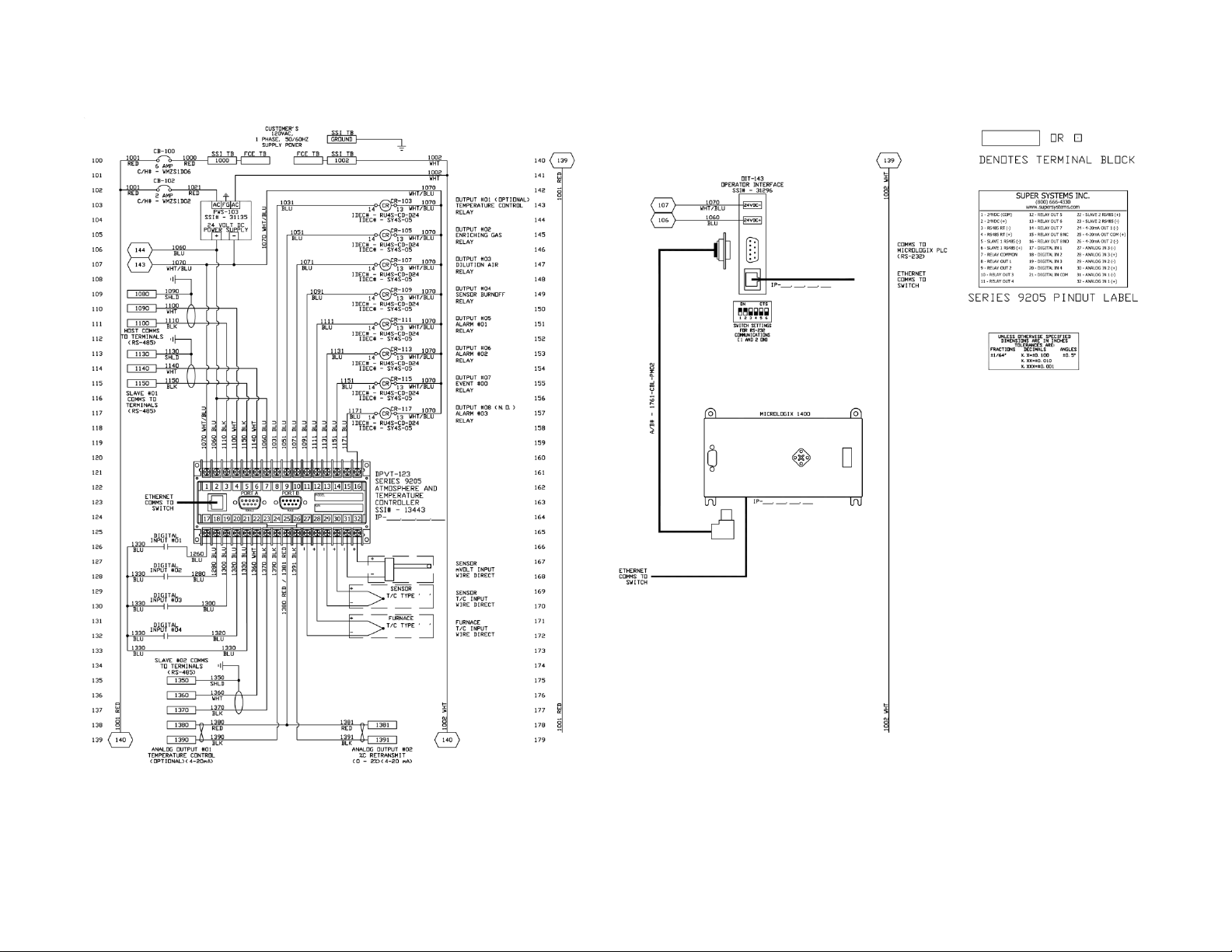
Super Systems Inc.
Page 58 of 60
3.5” Touch Screen
Compact HMI and Compact HMI Editor Operations Manual
Page 59

Super Systems Inc.
Page 59 of 60
5.7” Touch Screen
Compact HMI and Compact HMI Editor Operations Manual
Page 60

Super Systems Inc.
Page 60 of 60
12.1” Touch Screen
Compact HMI and Compact HMI Editor Operations Manual
 Loading...