

Page 1

CarbCalc II
Carbon Diffusion Model for
Atmosphere Furnaces
Copyright
Super Systems Inc
7205 Edington Drive
Cincinnati,OH 45249
Page 2

CarbCalc III
Table of Contents
Part I
Part II
Introduction
................................................................................................................................... 31 Welcome to SuperSystems
................................................................................................................................... 42 CarbCalcII Introduction
CarbCalcII
................................................................................................................................... 71 Overview
................................................................................................................................... 82 Typical Uses
................................................................................................................................... 93 Menu and Toolbar
................................................................................................................................... 104 Displays
.......................................................................................................................................................... 10Atmosphere Display Area
.......................................................................................................................................................... 11Model Segment Display Area
.......................................................................................................................................................... 12Segment Properties Dialog
.......................................................................................................................................................... 13Temperature and Carbon Chart
.......................................................................................................................................................... 14Carbon Profile Chart
................................................................................................................................... 155 Users and Security
.......................................................................................................................................................... 15Login
.......................................................................................................................................................... 16Manage Users
................................................................................................................................... 176 Parts and Loads
.......................................................................................................................................................... 17Loads
.......................................................................................................................................................... 17Control Mode
.......................................................................................................................................................... 20Monitor Mode
.......................................................................................................................................................... 21BatchMaster Mode
................................................................................................................................... 237 Model and Furnace Settings
.......................................................................................................................................................... 23Settings Overview
.......................................................................................................................................................... 23Model Settings
.......................................................................................................................................................... 24Furnace Settings
.......................................................................................................................................................... 26Furnace RealTime Setup
................................................................................................................................... 288 Material Selection
.......................................................................................................................................................... 28Material Dtabase
.......................................................................................................................................................... 29Initial Carbon Profile
................................................................................................................................... 319 Target Profile
.......................................................................................................................................................... 31Specifying a Target Profile
.......................................................................................................................................................... 32Recommended Profile
................................................................................................................................... 3310 Carbobn Profiles
.......................................................................................................................................................... 33Carbobn Profile Dialog
................................................................................................................................... 3611 SuperCalc
.......................................................................................................................................................... 36The SuperCalc Application
................................................................................................................................... 3712 Simulation Mode
.......................................................................................................................................................... 37Typical Uses
3
7
......................................................................................................................................................... 18Entering a Load
......................................................................................................................................................... 19Load History in Control Mode
......................................................................................................................................................... 19Parts in Control Mode
© 2005,2006,2007 Super Systems Inc.
Page 3

.......................................................................................................................................................... 37Report
................................................................................................................................... 3913 RealTime Control Mode
.......................................................................................................................................................... 39Typical Uses
.......................................................................................................................................................... 39Report
................................................................................................................................... 4114 Replay Monitor Mode
.......................................................................................................................................................... 41Typical Uses
.......................................................................................................................................................... 43Report
IIContents
Part III
CarbCalcII Configuration
44
Index 0
© 2005,2006,2007 Super Systems Inc.
II
Page 4

1 Introduction
1.1 Welcome to SuperSystems
Super Systems Inc.
Super Systems Introduces
Load Tracking and RealTime Control
No part of this publication may be reproduced, transmitted, transcribed, stored in a retrieval system, or
translated into any language or computer language, in any form or by any means, electronic,
mechanical, magnetic, optical, chemical, manual, or otherwise, without prior written permission of
Super Systems Inc., 7205 Edington Dr., Cincinnati, OH 45249 USA.
CARBCALCII is a software program to be used by the Heat Treater. Super Systems Inc. is not
responsible or liable for any product, process, or damage or injury incurred as a result of using
CARBCALCII. Super Systems Inc. makes no representations or warranties with respect to the
contents hereof and specifically disclaims any implied warranties or merchantability or fitness for any
particular purpose.
IntroductionCarbCalc II3
CarbCalcII
with
COPYRIGHT
DISCLAIMER
© 2005,2006,2007 Super Systems Inc.
Page 5
1.2 CarbCalcII Introduction
CarbCalcII is a Carbon Diffusion Model for use with Batch Furnace Gas Carburizing.
IntroductionCarbCalc II 4
Gas Carburizing
low-carbon steel part at a temperature sufficient to render the steel austenitic, followed by quenching
and tempering to form a martensitic microstructure. The resulting gradient in carbon content below the
surface of the part causes a gradient in hardness, producing a strong, wear-resistant surface layer on
a material, usually low-carbon steel, which is readily fabricated into parts. In gas carburizing the source
of carbon is a carbon-rich furnace atmosphere produced either from gaseous hydrocarbons, for
example, methane (CH4), propane (C3H3), and butane (C4H10), or from vaporized hydrocarbon
liquids.
Carbon Sources
Low-carbon steel parts exposed to carbon-rich atmospheres will carburize at temperatures of 850°C
(1560°F) and above. If the carbon source is so rich that the solubility limit of carbon in austenite is
reached at the surface of the steel some carbides may form at the surface. At these "above saturation"
atmospheres soot will deposit on surfaces within the furnace, including the parts. The goal of modern
gas carburizing practice is to control the carbon content of furnace atmospheres such that: The final
carbon concentration at the surface of the parts is below the solubility limit in austenite and Sooting of
the furnace atmosphere is minimized. Endothermic gas (Endogas) is a blend of carbon monoxide,
hydrogen, and nitrogen (with smaller amounts of carbon dioxide water vapor, and methane) produced
by reacting a hydrocarbon gas such as natural, gas (primarily methane), propane or butane with air. A
© 2005,2006,2007 Super Systems Inc.
is a case-hardening process in which carbon is dissolved in the surface layers of a
Page 6

IntroductionCarbCalc II5
carrier gas similar in composition to Endogas may be produced from methane can be formed from a
nitrogen-methanol blend.
Carburizing Process Variables
The gas carburizing process depends on the control of three principal variables:
·
Temperature
·
Time
·
Atmosphere composition.
Other variables that affect the amount of carbon transferred to parts include the degree of atmosphere
circulation and the alloy content of the parts.
Temperature
. The maximum rate at which carbon can be added to steel is limited by the rate of
diffusion of carbon in austenite. This diffusion rate increases greatly with increasing temperature; the
rate of carbon addition at 925°C (1700°F) is about 40% greater than at 870°C (1600°F). The
temperature most commonly used for carburizing is 925°C (1700°F). This temperature permits a
reasonably rapid carburizing rate without excessively rapid deterioration of furnace equipment. The
carburizing temperature is sometimes raised to 955°C (1750°F) or 980°C (1800°F) to shorten the time
of carburizing for parts requiring deep cases. Conversely, shallow case carburizing is frequently done
at lower temperatures because case depth can be controlled more accurately with the slower rate of
carburizing obtained at lower temperatures. For best results, the workload should be heated to the
carburizing temperature in a near-neutral furnace atmosphere. In batch furnaces, parts can be heated
in Endogas until they reach the furnace temperature; then carburizing can commence with the addition
of the enriching gas.
Time.
The effect of time and temperature on the Carbon vs Depth profile shows that the carburizing
time decreases with increasing carburizing temperature. In addition to the time at the carburizing
temperature, several hours may be required to bring large work pieces or heavy loads of smaller parts
to operating temperature. For a work piece quenched directly from the carburizing furnace, the cycle
may be lengthened further by allowing time for the work piece to cool from the carburizing temperature
to about 843°C (1550°F) prior to quenching. Similarly, additional diffusion and interchange of carbon
with the atmosphere will occur during cooling prior to quenching.
Carbon Potential.
The carbon potential of the furnace atmosphere must be greater than the carbon
potential at the surface of the work piece in order for carburizing to occur. It is the difference in carbon
potential that provides the driving force for carbon transfer into the parts.
Carbon Diffusion.
The combined effects of time, temperature, and carbon concentration on the
diffusion of carbon in austenite can be expressed by Fick's laws of diffusion.
Alloy Effects.
The various alloying elements found in carburizing steels have an influence on the
activity of carbon dissolved in austenite.
Chromium
·
Nickel
·
tends to decrease the activity of carbon
tends to raise the activity of carbon
The primary effect of alloys on the diffusion of carbon is their effect on the driving force at the surface
reaction.
The CarbCalcII Model
CARBCALCII is a carbon difussion model for simulation and analysis of gas carburizing process for
low-alloy steels. The interactions of the gas carburizing process cannot be modeled by simple
one-dimensional analysis. In order to accurately predict how a low-alloy steel will react in a controlled
atmosphere process, many factors must be taken into account, including:
·
Alloy steel composition
·
Equilibrium and non-equilibrium gas composition
·
Temperature
·
Atmosphere agitation
·
Surface radius of curvature, concave or convex
© 2005,2006,2007 Super Systems Inc.
Page 7

IntroductionCarbCalc II 6
·
Initial carbon profile
CARBCALCII takes as many factors as possible into account for the accurate prediction of (1) transfer
of carbon between gas and steel surface, and (2) diffusion of carbon within the steel.
Possible uses for CARBCALCII include:
·
Computer-aided design of heat treatment processes
·
Optimization of existing cycles
·
"What if" analysis when a change in an existing process or material is contemplated
·
Reconstruction of the effects that an out-of-control process may have had on a load
·
Education of personnel in the intricacies of atmosphere processing
·
Real-Time control with an on-line process
CARBCALCII can pay for itself quickly because process development experiments can be carried out
quickly on the computer instead of weeks in a furnace. When a trial is finally made in the furnace, the
results will be reasonably close to those predicted by the software.
CARBCALCII has thee main operating modes:
1. Simulation
2. RealTime Control
3. Monitor/Replay
The object in all cases is to accurately predict the diffusion gradient that carbon establishes in a given
material from a given set of processing parameters.
SIMULATION
allows construction of a diffusion gradient from complex a set of processing
parameters. For example, in a batch integral quench furnace, one might be interested in the following
sequence:
·
Come to Heat
·
Boost Carburize
·
Diffuse Carburize
·
Equalize for Quench
·
Brief Exposure to Vestibule Atmosphere
REALTIME CONTROL
- CarbCalcII is able to connect to "dumb controllers" via SuperData
communications. In this mode, CarbCalcII becomes the "Recipe Programmer" and sends setpoints to
the Temperature and Carbon Controllers.
MONITOR/REPLAY
running and logged in SuperData. This mode can be integrated with BatchMaster furnace control
systems.
© 2005,2006,2007 Super Systems Inc.
is used to view the Carbon Profile for load cycles previously run or currently
Page 8
2 CarbCalcII
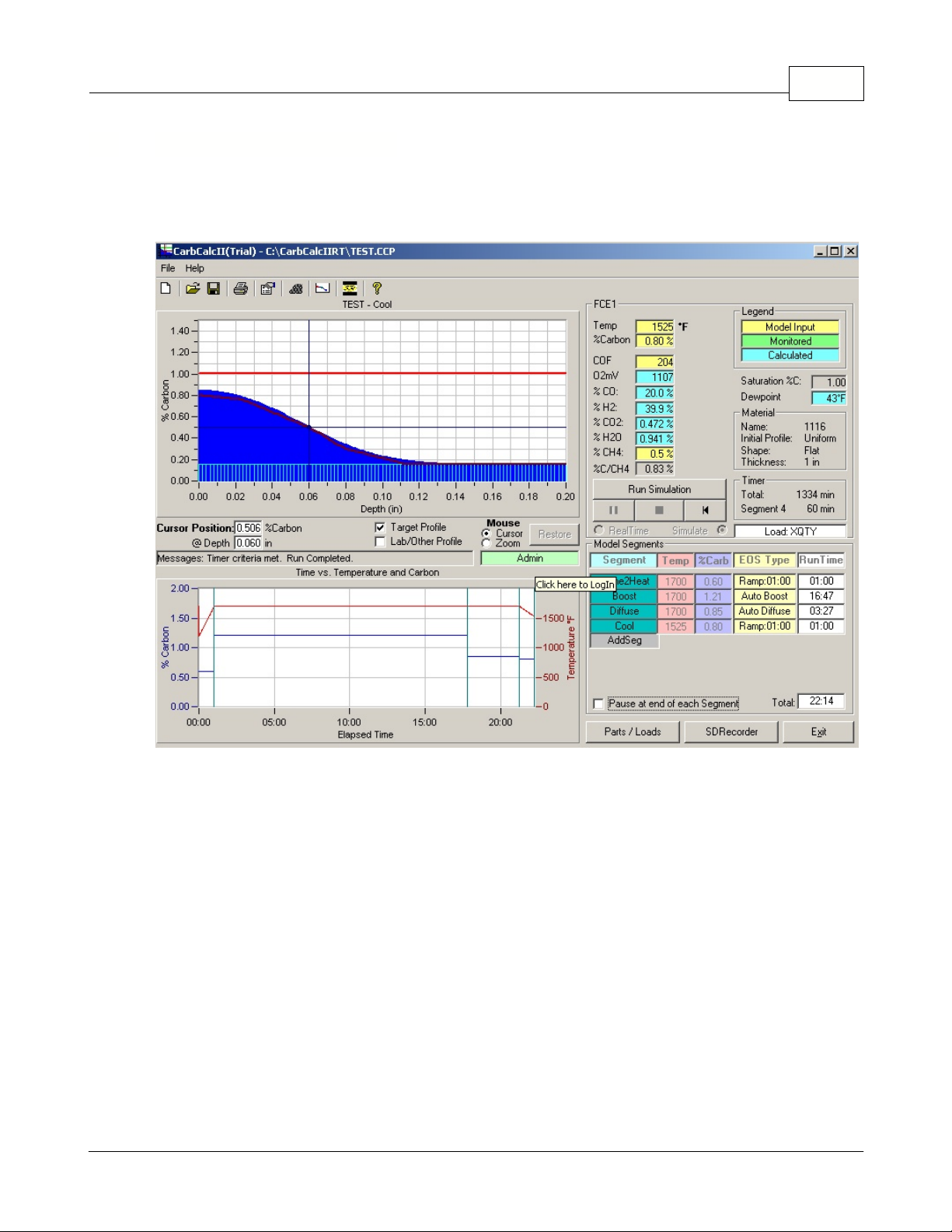
2.1 Overview
CarbCalcIICarbCalc II7
The Main Screen.
Menu and ToolBar:
·
Furnace Atmosphere Display:
·
material information and timers.
Recipe Segment Display:
·
Recipe Temperature and Carbon Chart:
·
displays segment markers.
Carbon Profile Chart:
·
Saturation Carbon line.
Provides access to Files, Printer and Model settings.
Displays Temperature, %Carbon and Gas values. Also displays
Displays the Recipe segments in the current model, (Max 8 segments).
Displays Initial Carbon, Carbon Diffusion profile, Target profile and
Displays theTemperature and Carbon vs Time. Also
© 2005,2006,2007 Super Systems Inc.
Page 9

2.2 Typical Uses
Simulation mode
In
·
Up to 8 segments may be modeled.
·
For each segment, define the Segment Name, Temperature, Carbon and End-Of-Segment (EOS)
type.
·
EOS types are:
1. Timed - ends after a specified time.
2. Match Surface Carbon - ends when Surface Carbon matches the Target Surface Carbon.
3. Match Carbon at a specified depth - ends when Diffused Carbon matches Carbon at a
specified depth.
4. Auto Boost - ends when the amount of excess carbon near the surface exceeds the deficient
carbon at depth.
5. Auto Diffuse - ends when the deviation between the diffused profile and the target profile is
minimized (curve matching).
·
Model Temperature units may be displayed in Celsius of Fahrenheit and Measurement units in
inches or mm.
·
Probe Factors may use either the CO Factor or the Process Factor (typical to Marathon
Instruments) .
·
The Type of Material may be selected from a Material Database.
·
The Initial Carbon Profile is based on the material selected and is assumed to be uniform.
·
The Initial Carbon Profile may be customized based on 10 points - useful for modeling "Rework"
recipes.
·
The Target Profile (up to 10 points) may be specified or you can request a recommended profile
based on Surface Carbon, Carbon at Effective Case Depth and Carbon at total Case Depth.
·
After starting the simulation, it may be paused at any time. You can also set it to "AutoPause" at the
end of each segment.
CarbCalcIICarbCalc II 8
, CabcalcII is used to develop Batch Carburizing Segment recipes.
RealTime Control mode
In
Controller and is used to Control a running Batch Furnace Carb Cycle.
·
A simple Load Entry system is used
·
The Segment display represents the Carb Cycle Recipe.
·
The Time vs Temperature and Carbon chart displays both the Setpoints and Actual values for
Temperature and Carbon.
·
The Carbon Profile is based on actual data from the instruments.
·
Instrument communication data sources are easily configured from within the application and saved
in a "Furnace" file.
Monitor/Replay mode
In
data logged by the SuperSystems communications datalogger. This mode is useful in analyzing a
comparing a cycle profile with the actual Profile from Lab results.· Display is similar to RealTime mode
but the data source is from the historical logged data.
·
Model runs at high speed similar to simulation mode.
·
Model may be paused, stopped or restarted at any time.
·
Target profile may be used to compare actual Lab measured profile for comparison with the model
results.
·
Analysis may be helpful in "Tuning" the recipe to achieve more precise results.
, CarbCalcII is connected to a Carbon Controller and a Temperature
, CarbCalcII is used to reproduce a cycle based on a Furnace Load and the
© 2005,2006,2007 Super Systems Inc.
Page 10
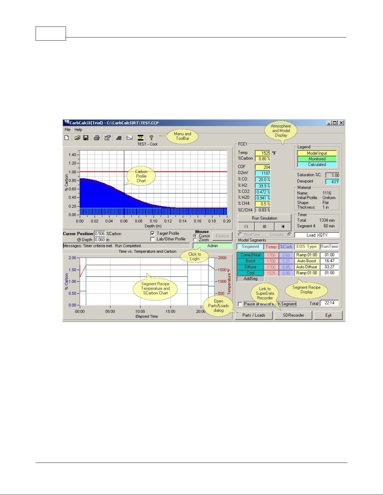
2.3 Menu and Toolbar
Menu Items
·
File
·
·
ToolBar Items
·
- Provides standard file open, save and close routines for CarbCalcII Model Files.
Help
- Opens Help file and About box.
CarbCalcIICarbCalc II9
New Model - Opens the default New Model
Save Model - saves the current model.· Print - prints the Carbon Profile report.
Model and Furnace Settings - Opens the
Model and Furnace settings dialog.
Carbon Profiles - Opens the Carbon Profiles
dialog.
Help - Opens this help file.
Open Model - displays the File Open
dialog for CarbCalcII Model Files
(report depends on model mode and settings see Reports in this help file)
Material - Opens the Material selection
dialog.
SuperCalc - Opens the SuperCalc
program.
© 2005,2006,2007 Super Systems Inc.
Page 11
2.4 Displays
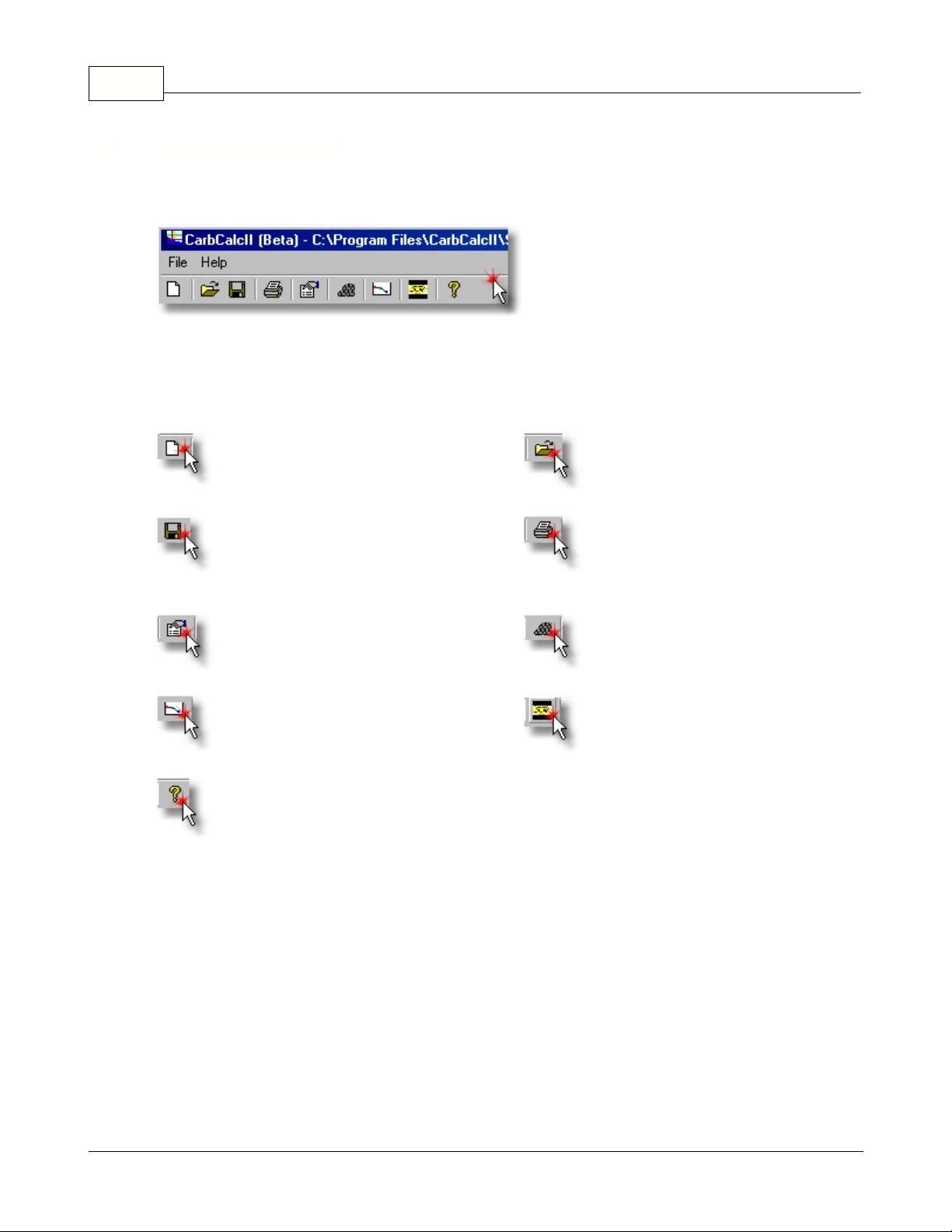
2.4.1 Atmosphere Display Area
CarbCalcIICarbCalc II 10
Atmosphere
·
All atmosphere values are displayed. Model Inputs (yellow background) are "given" or "assumed"
values. Monitored values (green background) are used only in the RealTime and Replay modes.
Calculated values (blue background) are calculated based on Model Inputs and the assumption that
the atmosphere is in equilibrium.
In simulation mode, the inputs will always be Temperature, %Carbon, Probe Factor and CH4. In
Realtime and Replay modes the model inputs are selectable. In these modes, data that is available
but not selected as a model input may be monitored - in this case, a monitored value will be displayed
next to the model value.
Temperature
·
%Carbon
·
PF or COF
·
O2mV
·
·
·
·
·
·
·
·
dependent on Temperature. When designing recipes, a good rule of thumb is to keep the %C
setpoint below about 90% of the Saturation Carbon.
- Oxygen Probe millivolts
%CO
- %Carbon Monoxide in the furnace atmosphere
%H2
- %Hydrogen Monoxide in the furnace atmosphere
%CO2
- %Carbon Dioxide in the furnace atmosphere
%H2O
- %Water in the furnace atmosphere
%CH4
%C/CH4
Saturation Carbon
- units may be in Fahrenheit or Celsius.
- Carbon Potential (based on water-gas equations)
- Process Factor or CO Factor (depends on type of controller)
- %Hydrocarbon in the furnace atmosphere
- Efective%Carbon with CH4 taken into consideration
- the level at witch free carbon (soot) precipitates in the atmosphere. Primarily
© 2005,2006,2007 Super Systems Inc.
Page 12
Dewpoint
·
Material
·
material toolbar icon.
Timers
·
Model Run Controls
·
- displays the calculated Dewpoint for the given atmosphere.
- displays the material selected, may be changed by opening the material dialog with the
-Displays the Total elapsed time and segment elapsed time in minutes.
- Used to start, stop, pause and reset the simulation.
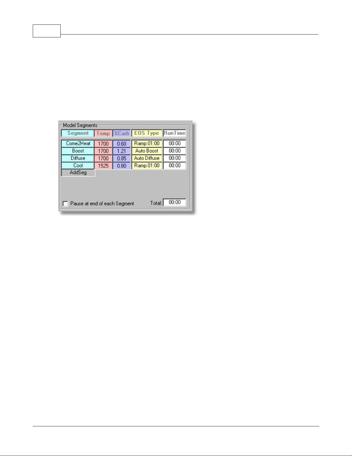
2.4.2 Model Segment Display Area
CarbCalcIICarbCalc II11
Model Recipe
A
Segment
·
paused or stopped, you may click on the segment name to open the segment properties dialog and
edit the segment.
Temp
·
·
·
·
·
·
·
·
- The temperature for the segment. You may edit the temperature for segments that have not
yet executed.
%Carb
executed.
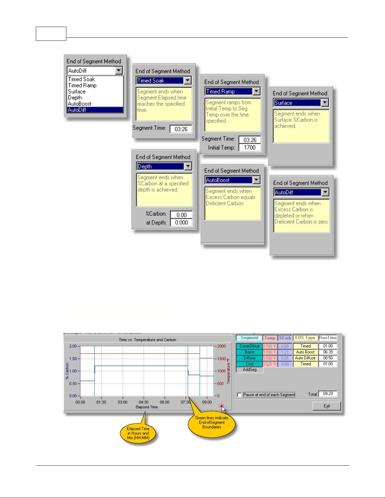
EOS Type
available:
RunTime
Pause Checkbox
end of each segment.
Total Timer
Note:
It is not normally not displayed during Monitor and Replay modes.
- The %Carbon for the segment. You may edit the %Carbon for segments that have not yet
Timed Soak
1.
Timed Ramp
2.
Surface
3.
Depth
4.
AutoBoost
5.
"Excess" carbon is the carbon above the "target" profile and "deficient" carbon is carbon below
the target profile.
AutoDiffuse
6.
The Model Segment Display Area is always used in Simulation and Realtime Control Modes.
may have up to 8 Segments.
- the name given to the segment (defaults to Seg1, Seg2, etc). When the simulation is
- The End-Of-Segment type determines how the segment terminates. There are 6 types
- ends after a given time is reached.
- ramps temperature ends after a given time is reached.
- ends when the Carbon profile "matches" a specified Surface Carbon.
- ends when the Carbon profile "matches" a specified carbon at a specified depth.
- ends when the "excess" carbon is sufficient to satisfy the "deficient" carbon.
- ends when the Carbon Profile matches the Target Profile ("best fit") .
- displays the segment time in days, hours and minutes (D:HH:MM).
- (simulation and replay only) check this box to make the simulation pause at the
- displays the total time in days, hours and minutes (D:HH:MM).
© 2005,2006,2007 Super Systems Inc.
Page 13
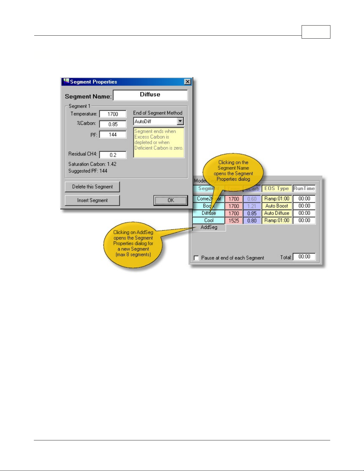
2.4.3 Segment Properties Dialog
CarbCalcIICarbCalc II 12
Segment Name
·
Temperature
·
%Carbon
·
Probe Factor
·
to the Suggested PF and may be edited.
Residual CH4
·
Saturation Carbon
·
this amount.
Suggested Probe Factor
·
selected.
End of Segment Method
·
below.
© 2005,2006,2007 Super Systems Inc.
- Enter or Edit the Segment Name.
- Enter or Edit the Segment Temperature
- Enter or Edit the Segment %Carbon.
(PF or COF) - Enter or Edit the Probe Factor. Note: for new segments this will default
- Enter or Edit the CH4 (normally 0.0 to 5.0 depending on your furnace).
- displays saturation carbon level, %Carbon should be set to a value less than
(PF or COF) - Theoretical value of the Probe Factor based on Material
- select the End of Segment type and supply required data as indicated
Page 14
CarbCalcIICarbCalc II13
Delete Button
·
Insert Button
·
OK Button
·
- clicking on this button will delete this segment from the model.
- clicking this button inserts the segment as a new segment.
- exits the dialog and saves changes to the segment.
2.4.4 Temperature and Carbon Chart
© 2005,2006,2007 Super Systems Inc.
Page 15
Simulation mode
In
executed.
RealTime
In
process variables and setpoints are displayed and times are displayed as actual clock times rather
than elapsed times.
and
, the Temperature and Carbon Chart displays a profile of the recipe as it is
Replay modes
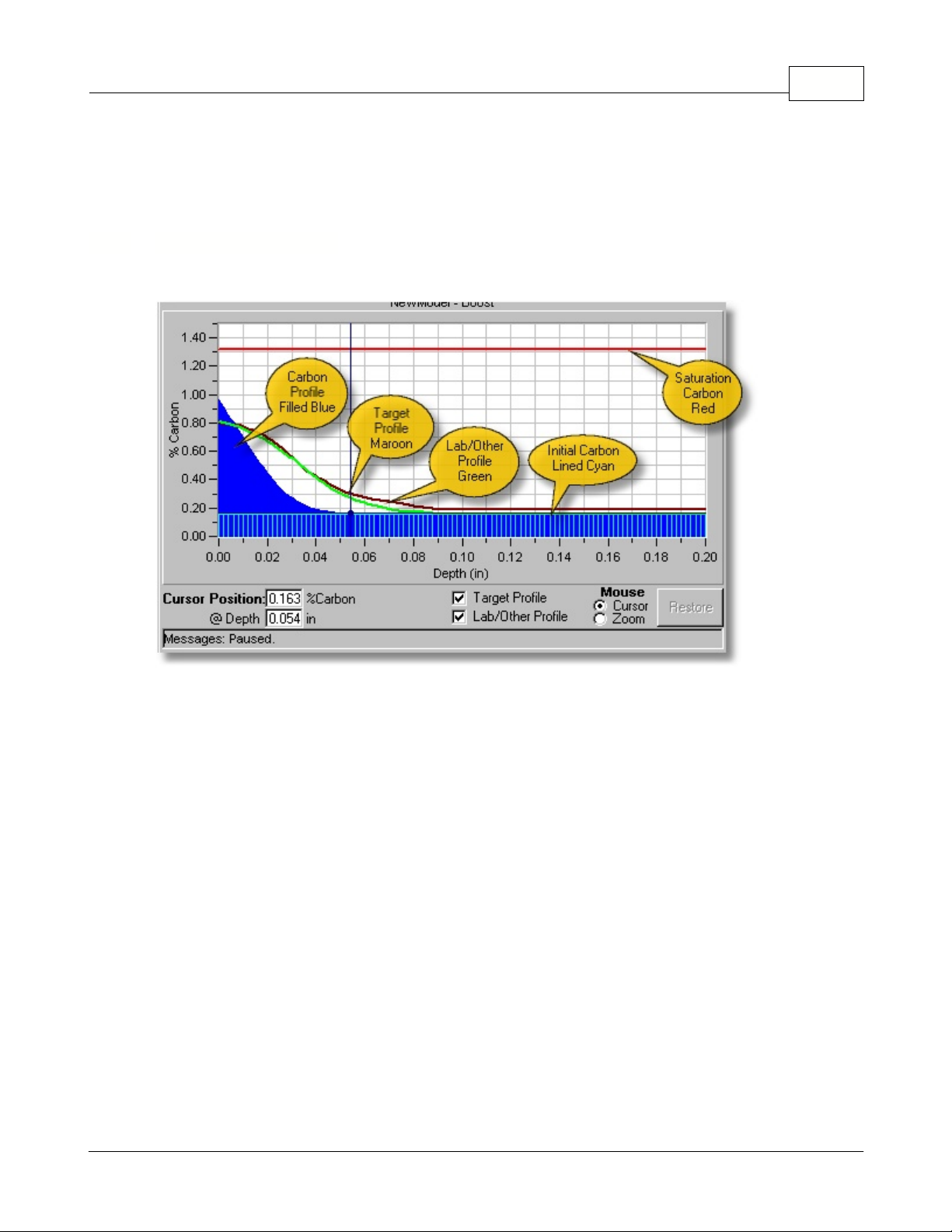
2.4.5 Carbon Profile Chart
CarbCalcIICarbCalc II 14
, the Actual monitored values of the Temperature and Carbon
The Carbon Profile Chart displays %Carbon (Y axis) vs Depth (X axis).
Title
·
In RealTime and Replay Modes, displays Load Name and Model Name.
·
·
·
·
·
·
·
·
·
·
·
·
·
- In Simulation mode, displays "Model Name - Segment Name"
Y Axis
X Axis
Cursor Position
Target Profile
Lab/Other Profile
Mouse Mode
Restore Button
Message box
Carbon Profile
Initial Carbon Profile
Target Profile
Lab/Other Profile
Saturation Carbon
- %Carbon
- Depth (in inches or mm depending on model settings)
- displays the %Carbon at Depth corresponding to the cursor crosshair position.
- check to display the target profile.
- check to display the Lab or other imported profile.
- places mouse in either cursor or zoom mode (default is cursor).
- used to restore the chart after using the zoom mode.
- message display.
- primary display (filled Blue) Carbon vs Depth
- Uniform or Custom Initial Carbon Profile (Lined Cyan)
- Maroon line indicating the "spec" or Target Profile
- Green line indicating the imported Lab or other imported Profile.
- Red Line indicating the "saturation" carbon for the given furnace temperature.
© 2005,2006,2007 Super Systems Inc.
Page 16

2.5 Users and Security
2.5.1 Login
Previous versions of CarbCalcII did not require Login or passwords. This version may be used to
control furnace cycles in a production environment and therefore requires some protection. For each
authorized user a User Name, Password and Access Level are maintained. When a user successfully
logs in, he is granted access to program features depending on Access Level, Run Mode and Run
Status.
A Login remains valid until 1) User Logs out or 2) In RealTime Control with program running Login is
valid for 15 minutes.
There are 6 Access Levels (0 through 5):
·
Level 0 - Guest
·
access to simulation modes
·
cannot save or create models, parts, or loads
·
Note: This is the default User Level
·
Level 1 - Basic Operator
·
Access level 0 plus
·
can start and stop realtime loads
·
Level 2 - Advanced Operator
·
Access level 1 plus
·
can save and create loads, parts and models
·
Level 3 - Supervisor
·
Access Level 2 plus
·
can add and edit Material in the Material database
·
Note: This is the default User Level for BatchMaster Integration
·
Level 4 - Advanced Supervisor
·
Access level 3 plus
·
Level 5 - Administrator
·
Access level 4 plus
·
Manage User accounts
·
Unrestricted access to all features
CarbCalcIICarbCalc II15
To Login, click on the User Name Display/Login button. The Login dialog will open as shown above.
·
Enter User Name (not case sensitive)
·
Enter Password (this is case sensitive)
·
Click Enter
·
Successful Login - User name will be displayed in the User Name Display with a green
background.
·
Unsuccessful login - message and Guest will be displayed as user name.
·
Click Cancel to logout (reverts to Guest)
© 2005,2006,2007 Super Systems Inc.
Page 17

Password restrictions:
·
Password cannot be blank
·
Password must be 3 or more characters or numbers
·
Password cannot be the same as user name (indicates reset)
Setting or changing a password. Only the Administrator can "reset" your password. When it is
reset, the password is set to the User Name. When you logon, you will be prompted to enter a new
password. If you forget your password, the Administrator can access it.
2.5.2 Manage Users
Only the Administrator (Access Level 5) can access the User's screen.
CarbCalcIICarbCalc II 16
When you login as Administrator, the buttons at the bottom of the login dialog will change to "Manage
Users" and "Continue". Click continue to complete the login normally. Click "Manage Users" to show
the Users Dialog.
·
Personnel Grid - Use the grid to Add, Edit or Delete Users.
·
Show Password - click and hold to display password for selected user.
·
Reset Password - click to reset the selected user's password. When reset, the password becomes
the User Name and must be changed on next login.
© 2005,2006,2007 Super Systems Inc.
Page 18

2.6 Parts and Loads
2.6.1 Loads
CarbCalcII comes with a Part and Load database. The user interface with the database varies
depending on the operating mode,
·
CarbCalcII in Control Mode - Loads and Parts integrated with Load Entry System.
·
CarbCalcII in Monitor Mode - Loadfs and Parts for display and replay of data.
·
CarbCalcII integrated with BatchMaster - BatchMaster Load database used for display and replay of
data.
2.6.2 Control Mode
The Parts and Loads dialog contains 3 tabs: New Loads, Completed Loads and Parts.
CarbCalcIICarbCalc II17
New Loads
select a load to run.
(Note: Yous must be logged in with access level 2 or higher to use this screen)
- This tab is used to build loads and add them to the Loads database. It is also used to
Load Name
·
load or type in a new name for a new load. The drop list will only display loads that have not been
completed.
Load Part
·
associated with that part.
Qty
·
- enter the quantity of parts in this load.
Operator
·
Load Remarks
·
Model
·
changed using the droplist)
- A unique name to identify the Load. You may use the drop list to select an existing
- Select a part for the load (when a part is selected, the Model will change to the model
- (optional) enter an identifier for the operator
- Optional remarks
- Select the model to use for this load (model is selected when you select a part, but may be
© 2005,2006,2007 Super Systems Inc.
Page 19

Save Load
·
Select Load
·
- Click to save the Load in the database (does not select the load for execution)
- Click to select the load for execution (also saves the load to the database)
2.6.2.1 Entering a Load
In the Control Mode, you may enter a new load and either "Save" it for later use or "Select" it for
current operations.
CarbCalcIICarbCalc II 18
Steps to Enter and execute a Load in Realtime Control Mode
1. Select Realtime Mode (the run button changes to 'Load Entry")
2. Click on "Load Entry" to open the New Loads dialog
3. Select a Load and click on the Select Load button
4. The button changes from "Load Entry" to Start Recipe.
5. At this point you should verify the recipe, profile, material etc. You may switch to "Simulation"
and make simulation runs before starting the recipe in RealTime control.
6. Make sure the furnace is physically loaded.
7. Start the recipe. When the recipe is running, the computer is sending setpoints to the Carbon
and Temperature controllers. Ath this point, CarbCalcII and the CarbCalc computer are
dedicated to controlling the recipe. If you attempt to stop CarbCalcII you will get a warning
message.
© 2005,2006,2007 Super Systems Inc.
Page 20

2.6.2.2 Load History in Control Mode
The Completed Loads Tab may be used to select loads for "Replay". Note: This tab is not available
when a load is active in control mode.
CarbCalcIICarbCalc II19
The Completed Load Tab is displays a grid of loads, most recently completed on top.
The "Time In" is stamped when the "Start Recipe" button is pressed and the "Time Out" is stamped
when the load is completed ("unloaded"). These times may be edited on this screen with the
appropriate access level. With appropriate access level, Loads may be edited, added or deleted from
the database using the grid view.
To replay a load, select the load with the arrow indicator and click on the "Set Selected Load" button.
2.6.2.3 Parts in Control Mode
The Parts Tab is used to associate parts with models.
© 2005,2006,2007 Super Systems Inc.
Page 21

CarbCalcIICarbCalc II 20
Select/Enter Part
·
Description
·
Select Model
·
Save
·
Note: A Model is a set containing the "Material", "Target Profile" and "Recipe". Models are normally
developed using CarbCalcII in the Simulation Mode.
- save changes
- enter/edit a part description.
2.6.3 Monitor Mode
The Parts and Loads dialog contains 3 tabs: New Loads, Completed Loads and Parts. In the Monitor
Mode, there is no control of the process. However, Loads may be manually added to the loads
database and replayed using SuperData's logged process data.
New Loads
(Note: Yous must be logged in with access level 2 or higher to use this screen)
- This tab is used to create loads and add them to the Loads database.
- Select an existing part or enter a new part name.
- Select the model to use when loading this part.
© 2005,2006,2007 Super Systems Inc.
Page 22

CarbCalcIICarbCalc II21
Load Name
·
Load Part
·
associated with that part.
Qty
·
- enter the quantity of parts in this load.
Operator
·
Load Remarks
·
Model
·
changed using the droplist)
Select Furnace
·
logged process data).
Start Date and Time
·
End Date and Time
·
date and time initializes to the start date and time)
Save Load
·
Select Load
·
In the Monitor Mode, the
Mode.
- A unique name to identify the Load.
- Select a part for the load (when a part is selected, the Model will change to the model
- (optional) enter an identifier for the operator
- Optional remarks
- Select the model to use for this load (model is selected when you select a part, but may be
- Select the furnace that ran this load (CarbCalcII must know where to get the
- Click to save the Load in the database (does not select the load for replay)
- Click to select the load for replay (also saves the load to the database)
2.6.4 BatchMaster Mode
BatchMaster Integration
The
BatchMaster Mode, the Loads database is provided and maintained by an external application
(normally AFC-Holcroft's BatchMaster system). In the BatchMaster Mode, CarbCalcII provides
simulation for modelling and Load Replay for monitoring cycles. Since the external application provides
the load information, parts, times, etc. the "
Completed Loads
" tab is provided in the BatcfhMaster" mode.
- Enter the estimated Load Start date and time (may be edited later)
- Enter the estimated load end date and time (may be edited later). (Note: End
Completed Loads
mode is a special case of CarbCalcII's Monitor Mode. In the
Parts
and
New Loads
Tabs operate the same as in the Control
Parts
" and "
" tabs are not provided. Only the "
© 2005,2006,2007 Super Systems Inc.
Page 23

CarbCalcIICarbCalc II 22
See the "Configuration" section for setting up the BatchMaster Integration mode.
© 2005,2006,2007 Super Systems Inc.
Page 24

2.7 Model and Furnace Settings
2.7.1 Settings Overview
CarbCalcIICarbCalc II23
Settings dialog
·
The
model
·
The
·
The
·
Any model may be used with any furnace.
contains the "recipe segments", the material, the target profile, etc.
Furnace
contains data specific to a furnace.
2.7.2 Model Settings
is used to select the Model and the Furnace.
© 2005,2006,2007 Super Systems Inc.
Page 25

CarbCalcIICarbCalc II 24
Select Mode
·
Model Units
·
Measurement
·
Carbon Profile Chart
·
X Axis
·
Y Axis
·
Add New Model
·
will be saved with the current model settings. The settings may be subsequently changed and
saved as desired.
Delete Mode
·
Save Model
·
model was last saved.
l - use this dropdown to select the desired model.
·Temperature - select Celsius or Fahrenheit
- select English or Metric
setting (Depth Axis) - Auto is recommended.
setting (Carbon Axis) - Auto is recommended.
- Clicking this button will prompt you to enter a name for the new model, the model
l - clicking this button will delete the current model.
- will save the current model and all changes that may have been made since the
2.7.3 Furnace Settings
© 2005,2006,2007 Super Systems Inc.
Page 26

CarbCalcIICarbCalc II25
Select Furnace
·
Default Atmosphere Settings
·
·
Set Use Standard H2 to CO ratio 2:1
·
or Specify Custom H2 to CO ratio
·
Specify a Furnace Factor ( range 0.0 to 2.5 with normal value of 1.0 )
Probe Factor
·
PF
·
- used by Marathon Instruments
COF
·
or
Furnace RealTime Setup
·
- use this dropdown to select the desired furnace.
- used by most instruments
- Clicking this button opens the RealTime setup dialog for the selected
furnace.
Add New Furnace
·
- Clicking this button will prompt you to enter a name for the new Furnace, the
furnace will be saved with the current furnace settings. The settings may be subsequently changed
and saved as desired.
Delete Furnace
·
Save Furnace
·
- clicking this button will delete the current furnace.
- will save the current furnace and all changes that may have been made since the
furnace was last saved.
© 2005,2006,2007 Super Systems Inc.
Page 27

2.7.4 Furnace RealTime Setup
CarbCalcIICarbCalc II 26
Furnace RealTime Settings
·
monitor/replay modes, they are not required for simulation mode. The realtime settings describe
what information is available from the furnace instrumentation and where it can be accessed from
SuperData. The realtime modes require SuperData communications and datalog system.
Installed Atmosphere control
·
Carbon Probe Controller
·
IR Analyze
·
Carbon Potential Determination
·
Temperature and %CH4 are always assumed to be model inputs.
Carbon and Probe Factor
·
Probe Millivolts and Probe Factor
·
Probe Millivolts and %CO
·
Analyzer).
%CO and %CO2
·
Data Sources
·
Data Name
·
Background color
·
·
Yellow - model input
·
Green - monitored but not used as model input
·
Blue - calculated value
·
Red - not used
Data Source
·
Select Data Source Dialog
·
r - select type installed or none.
- Uses %CO and %CO2 as model inputs (requires IR Analyzer).
- Displays the data source (SuperData channel and slot) for the models data values.
- name of the data value, Clicking on the Data Name opens the Data Source Dialog.
- displays the Channel, Slot and Multiplier location for the data value.
- The realtime settings are required for the realtime control and
- select yes or no.
- Select data values to be used as model inputs.·Note:
- Uses Carbon and Probe Factor as model inputs.
- Uses Probe millivolts and Probe Factor as model inputs.
- Uses Probe Millivolts and %CO as model inputs (requires IR
- the dialog is opened when you click on the Data Name. The dialog is
© 2005,2006,2007 Super Systems Inc.
Page 28

CarbCalcIICarbCalc II27
used to specify the data source values.
Chan
·
·
·
. - select the SuperData channel from the dropdown.
Slot
. - select the SuperData slot from the dropdown.
Default/Manual
- enter a default value - this value is used in the model when communications is
lost, the value is also used as a manual input value when the data is not available and the channel
is set to "(None)".
Multiplier
·
- SuperData data is always stored as integer with implied decimal points. e.g. 1.05 %C
would be stored as 105, For this reason, it is necessary to provide a multiplier to retrieve the
correct value. In the case of %Carbon, the multiplier is 0.01.
OK Button
·
- saves the changes for the current furnace (you must save the furnace settings to
make these changes permanent)
Cancel Button
·
- ignores any changes and exits the dialog.
·
Note: When in Control mode, you will also be prompted to supply the Setpoint Write
·
Locations.
© 2005,2006,2007 Super Systems Inc.
Page 29

2.8 Material Selection
2.8.1 Material Dtabase
Material database
The
Additional material may be added to the database. The Probe Factor calculated by the model takes
into account the composition of the steel. The %Carbon in the steel is used to set the initial Carbon
Profile for the model (uniform).
dialog allows selection of most standard material for the given model.
CarbCalcIICarbCalc II 28
Material grid
·
Material Shape
·
Material Thickness
·
Set Custom Profile
·
normally used for modeling re-work where the Initial Carbon Profile is no longer uniform as in new
steel.
Add New Material
·
OK Button
·
- Use the row selector to select the desired steel.
- select from Flat, Concave or Convex (not implemented - Flat is always used) .
- enter value, ( max value for the model is 1.0 inch or 25.4 mm )
- clicking this button opens the Custom Profile dialog. The custom profile is
- clicking this button opens the "Add New Material" dialog.
- applies changes to the current model and closes the material dialog.
© 2005,2006,2007 Super Systems Inc.
Page 30

CarbCalcIICarbCalc II29
The Add New Material dialog permits adding material to the database. You must specify a material
name and composition.
2.8.2 Initial Carbon Profile
The Initial Carbon Profile is assumed to be uniform based on the %Carbon in the steel. This is the
normal case for new product. In special circumstances, e.g. product to be re-worked, the Initial
Carbon Profile may be substantially different.
Chart Area
·
Depth and %Carbon Columns
·
- displays the initial %Carbon vs Depth.
- Values in yellow background have been entered, values between
© 2005,2006,2007 Super Systems Inc.
Page 31

CarbCalcIICarbCalc II 30
entered values are interpolated and displayed with a white background. Surface and Max Model
depth values are fixed.
Clear Set
·
Import Profile
·
- this button clears the yellow background for the Depth and %Carbon values respectively.
- permits importing (from a .tsv or .csv file) a carbon profile to be used as the initial
carbon.
Export Profile
·
OK
·
- accepts changes and applies them to the current model. Note changes are not saved with the
- permits exporting the initial carbon profile to an excell compatible .tsv or .csv file.
model, the next time the model is loaded it will revert to uniform carbon for the selected material.
© 2005,2006,2007 Super Systems Inc.
Page 32

2.9 Target Profile
2.9.1 Specifying a Target Profile
The Target Profile is normally the specified goal for the simulation. The Target Profile is used to
calculate excess and deficient Carbon during the "Auto Boost" segment and is used for curve
matching in the "Auto Diffuse" segment.
Note: The Boost Diffuse Carbon cycle normally results in a profile that is "S" shaped. The principal
points in describing the curve are:
·
Surface - surface %Carbon
·
Plateau - %Carbon at half of the effective case depth to produce an "s" shape curve.
·
Effective Case - Depth/Carbon for the effective case depth.
·
Total Case - Depth/Carbon for the total case depth (Carbon defaults to the %Carbon in the
material).
·
Max Model - Always 1 inch (25.4 mm) with carbon the same as the material initial carbon.
CarbCalcIICarbCalc II31
Chart Area
·
Depth and %Carbon Columns
·
entered values are interpolated and displayed with a white background. Surface and Max Model
depth values are fixed.
Clear Set
·
Import Profile
·
Profile.
Export Profile
·
Recommend Profile
·
OK
·
- accepts changes and applies them to the current model.
- displays the Target Profile as %Carbon vs Depth.
- Values in yellow background have been entered, values between
- this button clears the yellow background for the %Carbon values.
- permits importing (from a .tsv or .csv file) a carbon profile to be used as the Target
- permits exporting the Target carbon profile to an excell compatible .tsv or .csv file.
- opens the "Recommend Profile" Dialog.
© 2005,2006,2007 Super Systems Inc.
Page 33

2.9.2 Recommended Profile
The Recommended Profile dialog permits easy entry of the target profile based on Surface
Carbon,Carbon at the Effective Case Depth and Carbon at Total Case Depth.
CarbCalcIICarbCalc II 32
·
Edit Carbon and Depth values as desired
·
Cancel - ignores any changes and closes the dialog.
·
OK - Applies changes and closed the dialog.
© 2005,2006,2007 Super Systems Inc.
Page 34

2.10 Carbobn Profiles
2.10.1 Carbobn Profile Dialog
CarbCalcIICarbCalc II33
There may be up to 4 simultaneously displayed on CarbCalcII's Carbon profile chart:
·
Current Predicted Carbon - The model's current predicted carbon profile
·
Initial Carbon - The material's initial carbon profile
·
Target Carbon - The target or specification carbon profile
·
Lab/Other Carbon - An imported Carbon profile, may be from lab data or other source.
Clicking on the Carbon Profiles toolbar icon opens the Carbon Profile dialogue with the Target Profile
active.
© 2005,2006,2007 Super Systems Inc.
Page 35
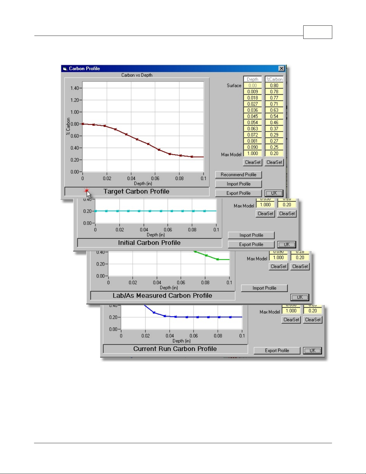
Clicking on the Active Profile Title box will switch the dialog to the next profile.
CarbCalcIICarbCalc II 34
Chart Area
·
Depth and %Carbon Columns
·
- displays the Active Profile as %Carbon vs Depth.
entered values are interpolated and displayed with a white background. Surface and Max Model
depth values are fixed.
Clear Set
·
Import Profile
·
- this button clears the yellow background for the Depth or %Carbon values respectively.
- permits importing (from a .tsv or .csv file) a carbon profile to be used as the
selected Active Profile (Target, Initial or Lab).
Export Profile
·
Recommend Profile
·
© 2005,2006,2007 Super Systems Inc.
- permits exporting the Active carbon profile to an excell compatible .tsv or .csv file.
- Values in yellow background have been "set", values between
- opens the "Recommend Profile" Dialog (Target Profile only).
Page 36

OK
·
- accepts changes and applies them to the current model.
CarbCalcIICarbCalc II35
© 2005,2006,2007 Super Systems Inc.
Page 37

2.11 SuperCalc
2.11.1 The SuperCalc Application
SuperCalc is an SSi Utility that aids in determining Carbon and Dewpoint based on Oxygen Probe or
3Gas IR analyzer. This utility is included with CarbCalcII and is also available on the web at
SuperSystems.com
CarbCalcIICarbCalc II 36
© 2005,2006,2007 Super Systems Inc.
Page 38

2.12 Simulation Mode
2.12.1 Typical Uses
The Simulation mode provides a method for developing Carb Cycle recipes for Batch Furnaces.
Typical uses include:
·
·Developing recipes for new product.
·
·Developing re-work recipes.
·
·Modifying existing recipes to potentially shorten furnace time.
In the Simulation mode, model inputs are always Temperature, %Carbon, Probe Factor and %CH4.
The Simulation Mode features various methods to model the End of Segment.
·
Timed segments
·
Match Surface Carbon
·
Match Carbon at a specified depth
·
Auto Boost
·
Auto Diffuse
CarbCalcIICarbCalc II37
Typical Steps in developing a Boost-Diffuse Carburizing Recipe
1.
Select the Furnace
2.
Select the Material
3
. Generate a Target Profile (Use recommended profile and modify as desired)
4
. Generate recipe segments
·
Usually 4 segments will be adequate (Come2Heat, Boost, Diffuse, Equalize)
·
Come2Heat - Soak for specified time
·
Boost - Use "AutoBoost" to end segment. %Carb should be just less than saturation for the
given temperature.
·
Diffuse - Use "AutoDiff" to end segment. %Carb should be at or slightly above the Target
Profile Surface Carbon.
·
Equalize/Cool - Timed Soak
5
. Run Simulation and evaluate results.
6
. Modify model (steps 2,3 and 4 above) and repeat simulation.
7
. When satisfied with simulation results, make a product test run,
8
. Compare test run lab results with simulation results (may use "Lab Profile" to aid in comparison).
9
. May be necessary to adjust the "Furnace Factor" to correct for differences in Lab Profile and
Simulation Profile.
Note 1:
Note 2:
When developing a "re-work" recipe, you will need to modify the "Initial Profile", all other
steps remain the same.
When modifying an existing recipe, replace the 4 segment cysle in step 4 with your existing
recipe.
2.12.2 Report
In the simulation mode, clicking on the print icon will print the following report. The report is a
snapshot of the current model status and can be printed at any time during the simulation.
© 2005,2006,2007 Super Systems Inc.
Page 39

CarbCalcIICarbCalc II 38
© 2005,2006,2007 Super Systems Inc.
Page 40

2.13 RealTime Control Mode
2.13.1 Typical Uses
In the RealTime Control Mode, a Carb Cycle may be controlled via SuperData Communications.
Typical uses include:
Controlling a Carbon Cycle Recipe and monitoring the Carbon Profile in RealTime
In the RealTime mode, Model inputs include Temperature and %CH4 and either Probe Data or IR
Analyzer Data for Carbon Potential determination.
2.13.2 Report
In the RealTime Control mode, clicking on the print icon will print the following report. The report is a
snapshot of the current model status and can be printed at any time during the run.
CarbCalcIICarbCalc II39
© 2005,2006,2007 Super Systems Inc.
Page 41

CarbCalcIICarbCalc II 40
© 2005,2006,2007 Super Systems Inc.
Page 42

2.14 Replay Monitor Mode
2.14.1 Typical Uses
The Replay/Monitor mode may be used to review potential probelms with a load and as an aid in
determining what may have gone wrong. The Replay/Monitor mode may be used in conjunction with
the RealTime control Mode or with Superdata Datalog and a manually maintained Loads Database, or
with BatchMaster Integration using an external Loads database.
Replay Monitor in conjunction with the RealTime Control Mode.
The Replay mode is similar to the RealTime Control Mode. When a Carb Cycle is run in Control
Mode, the following data is saved:
·
Load Information - in the CCLoads Database
·
Model as run - an "as run" model file is saved under the name "L-xxx-model.ccp" (where xxx=load id
number and model=model name)
·
Logged Process data - SuperData Communications historically logged data.
Using this data, the Cycle can be selected from the CCLoads database and may be replayed.
CarbCalcIICarbCalc II41
Replay Monitor With SuperData and a Manual Database.
This method is used when the Control Mode is not used. This method requires that the RealTime
Data Sources be configured for each furnace supported. This method also requires that a Load be
© 2005,2006,2007 Super Systems Inc.
Page 43

CarbCalcIICarbCalc II 42
manually entered using the Load Entry Screen. Load Entry must include a Load Start and Load End
time.
·
Load Information - manually entered in the CCLoads Database
·
Model as run - after the first replay, an "as run" model file is saved under the name
"L-xxx-model.ccp" (where xxx=load id number and model=model name)
·
Logged Process data - SuperData Communications historically logged data.
Using this data, the Cycle can be selected from the CCLoads database and may be replayed. During
replay, the recipe will be displayed, but only the total time (not segment times) will be displayed. This
is becaause the actual recipe used in the control instrument is unknown to CarbCalcII; only the logged
data and start/ent times are known.
Replay Monitor With BatchMaster Integration and an External Database.
This method is used when an external Load Entry system and Database are used (e.g with
BatchMaster or other Load Tracking systems). This method requires that the RealTime Data Sources
be configured for each furnace supported. This method also requires that the External Database must
be available through an ODBC DSN and that the carbcalc.ini file be configured for Load Database
access (see configuration section).
·
Load Information - obrtained from an external Load Tracking Database
·
Model as run - initial replay uses default settings, saving the load settings saves an "as-run" model
file for the load the name "BML-xxx-model.ccp" (where xxx=load id number and model=model
name)
© 2005,2006,2007 Super Systems Inc.
Page 44

CarbCalcIICarbCalc II43
·
Logged Process data - SuperData Communications historically logged data.
Using this data, the Cycle can selected from the CCLoads database and may be replayed. During
replay, the recipe will not be displayed; only the total time will be displayed. This is becaause the
actual recipe used in the control instrument is unknown to CarbCalcII; only the logged data and
start/ent times are known.
2.14.2 Report
n the Replay mode, clicking on the print icon will print the following report. The report is a snapshot of
the current model status and can be printed at any time during the replay.
© 2005,2006,2007 Super Systems Inc.
Page 45

CarbCalcIICarbCalc II 44
3 CarbCalcII Configuration
CarbCalcII is supplied in a fully functional 30 day "Trial" version. To continue using CarbCalcII beyond
the 30 day time limit, it must be registered and purchased from Super Systems Inc. Instructions for
registering ar contained in the Help/About screen.
CarbCalcII will require some configuration at time of installation.
CarbCalc
·
No configuration required
CarbCalc
·
Communications Data Sources must be configured for each furnace. (part of furnace settings)
© 2005,2006,2007 Super Systems Inc.
Simulation
RealTime Control, Replay and Monitoring
mode
modes
Page 46

CarbCalcII ConfigurationCarbCalc II45
CarbCalc.ini file :
This file will be located in the same directory that contains CarbCalcII.exe (the
application directory). This file is used to configure some operating modes, and database locations
and external database structure.
General
The
·
TID = xxxx (where xxxx = a 4 digit TrialID number. Do not remove this number, you may lose your
section
registration.)
·
RTMONITOR=x (where x=0 or 1. When set to 1, puts CarbCalc in a Replay/Monitor mode using
CCLoads Database)
·
BMIntegration=x (where x=0 or 1. When set to 1, puts CarbCalc in a BatchMaster Monitor mode
using and external Database)
Databases
The
·
Material=<name>.mdb (where <name> is the name of the material access database (default
carbcalc.mdb
·
CCLoads=<name>.mdb (where <name> is the name of the CarbCalc Load access database
(default
section
if not specified)
CCLoads.mdb
if not specified)
Note: the database names may be filename only (assumes file is in the application directory) or full
path and filename.
BMLoads
The
·
DSN=<name> (where <name> is the ODBC DSN)
·
T_LOAD=<name> (where <name> is the table name for the table containing the load information)
·
F_ID=<name> (where <name> is the field name for the numeric field containing the load ID)
·
F_LNAME=<name> (where <name> is the field name for the character field containing the load
section (only required when BMIntegration=1, ignored otherwise)
Name)
·
F_FCE=<name> (where <name> is the field name for the character field containing the Furnace
Name)
·
F_TIMEIN=<name> (where <name> is the field name for the datetime field containing the Load Start
time)
·
F_TIMEOUT=<name> (where <name> is the field name for the datetime field containing the Load
End time)
·
F_LINFO=<name> (where <name> is the field name for a character field containing additional Load
Information)
·
F_COMMENTS=<name> (where <name> is the field name for a character field containing additional
LoadComments)
Sample Carbcalc.ini file
[General]
*trial ID
TID= 9638
RTMONITOR=0
BMIntegration=1
[DataBases]
Material=carbcalc.mdb
CCLoads=C:\ssi\data\CCLoads.mdb
[BMLoads]
DSN=BM1
T_LOAD=Loads
© 2005,2006,2007 Super Systems Inc.
Page 47

F_ID=LID
F_LNAME=LoadNo
F_FCE=FceName
F_TIMEIN=StartDT
F_TIMEOUT=EndDT
F_LINFO=Recipe
F_COMMENTS=Part
CarbCalcII ConfigurationCarbCalc II 46
© 2005,2006,2007 Super Systems Inc.
 Loading...