

Page 1
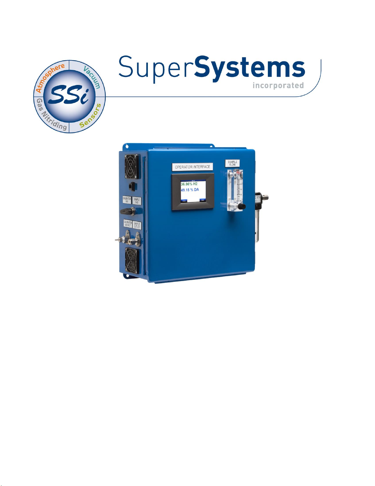
Basic Nitriding Sampling System
Hydrogen Analyzer with Calculated % DA,
% NH
3,
and K
N
Values
PN: 13537
Operations Manual
Please read, understand, and follow these instructions before operating this equipment.
Super Systems, Inc. is not responsible for damages incurred due to a failure to comply with these
instructions. If at any time there are questions regarding the proper use of this analyzer, please contact
us at 513-772-0060 for assistance.
Page 2

Basic Nitriding Sampling System – Hydrogen Analyzer
Super Systems Inc. Page 2 of 16
Super Systems Inc.
USA Office
Corporate Headquarters:
7205 Edington Drive
Shipping Address:
7245 Edington Drive
Cincinnati, OH 45249
Phone: (513) 772-0060
http://www.supersystems.com
Super Systems Europe
Unit E, Tyburn Trading Estate,
Ashold Farm Road, Birmingham
B24 9QG
UNITED KINGDOM
Phone: +44 (0) 121 306 5180
http://www.supersystemseurope.com
Super Systems México
Sistemas Superiores Integrales S de RL de CV
Acceso IV No. 31 Int. H Parque Industrial
Benito Juarez
C.P. 76120 Queretaro, Qro.
Phone: +52 442 210 2459
http://www.supersystems.com.mx
Super Systems China
No. 369 XianXia Road
Room 703
Shanghai, CHINA
200336
Phone: +86 21 5206 5701/2
http://www.supersystems.cn
Super Systems India Pvt. Ltd.
A-26 Mezzanine Floor, FIEE Complex,
Okhla Indl. Area, Phase – 2
New Delhi, India 110 020
Phone: +91 11 41050097
http://www.supersystemsindia.com
Page 3

Basic Nitriding Sampling System – Hydrogen Analyzer
Super Systems Inc. Page 3 of 16
Table of Contents
Introduction ................................................................................................................................................... 4
Specifications ................................................................................................................................................ 4
Electrical Connections / Terminal Assignments ........................................................................................... 4
Getting Started .............................................................................................................................................. 5
Default Settings ............................................................................................................................................. 5
Modifying the Default Settings ...................................................................................................................... 5
Description of Menu Items ............................................................................................................................ 5
Exit Program ................................................................................................................................................... 5
Instrument Information .................................................................................................................................. 5
Communication Setup ..................................................................................................................................... 5
Instrument Configuration ............................................................................................................................... 5
Percent Hydrogen ....................................................................................................................................... 6
Percent Dissociation................................................................................................................................... 6
Percent Ammonia ....................................................................................................................................... 6
Minimum H2 for NH3 Display Parameter .............................................................................................. 6
Nitriding Potential ...................................................................................................................................... 6
Output Configuration ....................................................................................................................................... 6
Output Calibration ........................................................................................................................................... 6
Sensor Calibration .......................................................................................................................................... 7
Performing a Zero Calibration ................................................................................................................... 7
Performing a Span Calibration .................................................................................................................. 7
Trend Chart...................................................................................................................................................... 8
Chart Sub Menu ............................................................................................................................................. 10
Control Interface Options ............................................................................................................................ 11
Parts List and Internal Components ........................................................................................................... 11
Warranty ...................................................................................................................................................... 13
Revision History .......................................................................................................................................... 14
Appendix A: Drawings (Electrical, Plumbing, and Mounting) ...................................................................... 15
Page 4

Basic Nitriding Sampling System – Hydrogen Analyzer
Super Systems Inc. Page 4 of 16
Introduction
This instrument uses the measurement of Hydrogen to display % Hydrogen (H2), % Dissociation (DA), and
% Ammonia (NH3). When the flow rates of Nitrogen, Ammonia, and Dissociated Ammonia are manually
entered, the instrument can also calculate Nitriding Potential (KN).
It is suggested that this device should be calibrated on a routine basis, such as once per year or as
prescribed by the user’s quality system requirements.
Specifications
Power Requirements: 100-240 VAC
Current Draw: Max. 0.2 Amps
Sensor Technology: Thermal Conductivity
User Interface: 3.5” Color QVGA TFT LCD Touch Screen
Measurement Range: 0-100% H
2
Hydrogen Measurement Accuracy: +/- 1%
Hydrogen Measurement Repeatability: +/- 1%
Hydrogen Measurement Resolution: 0.01%
Analog Outputs: Two Isolated 4-20mA (User Configurable)
Analog Output Resolution: 0.005mA
Analog Output Accuracy: +/- 0.01% of Range
Analog Output Linearity: +/- 0.01%
Analog Output Load Resistance: Minimum 0 Ohm, Maximum 500 Ohm
Digital Communications: RS485 Modbus, Ethernet
Enclosure Size (Without Filter): Approx. 13”L x 13”W x 6”D / 330mmL x 330mmW x 142mmD
Enclosure Weight: 22.5 lbs. / 10.2 kg.
Enclosure Ventilation: Continuous Purge Fan, Dual Vents
Recommended Flow Rate: 1.5 to 2.0 SCFH / 0.71 to 0.94 lpm
Process Gas Fittings: Stainless Steel Compression for ¼” OD Tubing
Calibration Gas Fitting: 1/8” Barb (can be removed for 1/8” Female NPT Port)
Operating Environment: 10-90 %RH (Non-Condensing)
Operating Temperature: 32 to 122°F / 0 to 50°C
Sample Gas Temperature: 32 to 158°F / 0 to 70°C
Electrical Connections / Terminal Assignments
Wire Number
Function
1000
AC Line Power (100-240VAC)
1002
AC Neutral Power
Ground
AC Ground
1121
Analog Output Common (+)
1111
Analog Output #1 (-)
1121
Analog Output Common (+)
1131
Analog Output #2 (-)
1081
RS485 (-)
1091
RS485 (+)
Page 5

Basic Nitriding Sampling System – Hydrogen Analyzer
Super Systems Inc. Page 5 of 16
Getting Started
Please refer to the enclosed drawing for instructions regarding the proper electrical and mechanical
installation of this instrument. The flow meter on the door of the enclosure should be adjusted to
maintain 1.5 SCFH of process gas flow.
Default Settings
When the instrument is turned on, it will display % H2 on the screen. To display additional values (% DA,
% NH3, or KN), see the “Instrument Setup” screen. The first 4-20mA output will be set up to retransmit
the %H2 value scaled for 0 to 100%, and the second output will be set up for %DA also scaled for 0-100%.
Any changes to these default parameters will be stored so they will not need to be re-entered when the
power is shut off to the instrument
Modifying the Default Settings
To access the operational and setup parameters, press the “menu” button at the lower left section of the
screen. This will allow you to select only two options, Exit Program and Instrument Information. To
prevent unwanted modification to the operation of the instrument, these are the only options available
unless the user logs in. To access the other menu options, press the “Login” button and enter “2”. This
will give the operator access to the setup and operational parameters.
Each individual menu option is described in detail below:
Description of Menu Items
Exit Program
The touch screen display is constantly writing data to its flash card for storage, and it is important that
the instrument not be shut down during this process. Before removing power from the enclosure, select
“Exit Program”. It will ask is you are sure that you want to shut down the interface. By answering yes, it
closes the operating program in an orderly manner. Once the standard Microsoft Windows screen
appears it is safe to remove power from the instrument. If this procedure is not followed, there is a
chance that there could be an error writing to the flash card that could cause problems with the operation
of the instrument.
Instrument Information
This screen provides information on any applicable revision levels and serial numbers. It also shows if
the instrument is logging data. There are no functions that can be performed on this screen; it is for
informational purposes only.
Communication Setup
The communication methods shown on this screen are for display only and cannot be modified. The baud
rates can be adjusted but they have been optimized for this instrument and modification is not
recommended.
Instrument Configuration
This instrument is capable of displaying four different parameters. These include:
Percent Hydrogen (H
2
)
Percent Dissociation (DA)
Percent Ammonia (NH
3
)
Nitriding Potential (K
N
)
Page 6

Basic Nitriding Sampling System – Hydrogen Analyzer
Super Systems Inc. Page 6 of 16
The Percent Hydrogen is displayed on the main screen at all times. One additional parameter can be
displayed along with Hydrogen by highlighting it and pressing the “OK” button. A clearer description of
each of these parameters can be found in Appendix “A”, Gas Nitriding Technical paper.
Percent Hydrogen
The percent hydrogen is the amount of Hydrogen that is being detected by the thermal conductivity
sensor inside the instrument. There are no additional calculations being performed to this value.
Percent Dissociation
Dissociation is derived from the amount of Hydrogen in the sample gas.
Percent Ammonia
The amount of Ammonia can also be inferred from the Hydrogen value.
Minimum H2 for NH3 Display Parameter
This analyzer measures %H2 (in ppm) and calculates a gas composition of DA or NH3 (with %DA + %NH3
= 100%). An available analog output provides a 4-20mA signal representing either DA or NH3--defaulting
to 4mA when zero hydrogen is measured.
Due to the high accuracy of the sensor, trace amounts of Hydrogen may be measured in "near zero"
environments, resulting in oscillations between 4- and 20mA when configured for %NH3. To prevent such
oscillations the user may define a Minimum H2 to fix the output at 4mA until the measured Hydrogen
percentage exceeds such a threshold.
Nitriding Potential
The accurate calculation of Nitriding Potential (KN) requires the flow rates of other gases that are being
introduced into the process. These flow rates are measured in SCFH (Standard Cubic Feet per Hour). KN
can only be calculated by entering the flow of Nitrogen (N2), Ammonia (NH3) and % Dissociated Ammonia
(%DA). These values are entered at the bottom of the main screen when KN is selected.
Output Configuration
There are two 4-20mA outputs that can be configured for any of the four parameters. For each input, the
operator can select the Source (H2, DA, NH3, KN), the zero value (the value to be represented by 4mA) and
the span value (the value to be represented by 20mA).
Output 1 can be measured from Terminal #1121(+) and 1111 (-).
Output 2 can be measured from Terminal #1121(+) and 1131 (-).
Output Calibration
Accurate retransmission of the selected parameters can only be obtained through calibrating both of the
analog outputs. This is done at the factory prior to shipment, however it is a relatively simple procedure
that can be performed in the field if desired. To perform a calibration, a multimeter with a current input
is required. Please keep in mind that the accuracy of the instrument used to calibrate the outputs is
directly related to the accuracy of the outputs after calibration, so a meter calibrated against NIST
(National Institute of Standards and Technology) standards is preferred. Before performing any
calibrations, all other devices must be disconnected from the analog outputs. Multiple devices on the
outputs will cause inaccurate measurement of current.
Attach the leads of the multimeter to the terminals for Output 1. The positive lead should be attached to
Terminal #1121 and the negative lead to Terminal 1111. Select “Zero Output 1” and press the “Prep for
Cal” button. The low limit of the output is 4mA, so 4.000 is shown as the default measured value. Ideally
the meter connected to the outputs will also show 4.000. If the two values are not close enough to obtain
the desired level of accuracy, a calibration should be performed.
Page 7

Basic Nitriding Sampling System – Hydrogen Analyzer
Super Systems Inc. Page 7 of 16
If, for example, the meter connected to the outputs reads 4.216mA, then the value “4.216” should be
entered on the screen as the Measured Value. Once the value has been entered, press the “calibrate”
button. This will offset the mA output of the instrument in an amount that results in an exact output of
4.000mA. When the calibration is complete, the multimeter should be reading 4.000mA (+/- .005).
The procedure can be repeated for the Span of Output 1. When “Span Output 1” is selected and “Prep for
Cal” is pressed, the instrument will output the high output limit, which is 20mA. The multimeter will
display the actual output from the instrument, and if it is not within the desired tolerance it can be
calibrated using the same procedure as above.
To calibrate Output 2, attach the leads of the multimeter to Terminal #1121 (+) and the negative lead to
Terminal 1131 (-) and follow the same procedure that was used for the first output.
Sensor Calibration
It is suggested that this device should be calibrated on a routine basis, such as once per year or as
prescribed by the user’s quality system requirements.
A proper calibration of the sensor requires two gases. The first gas should be pure Nitrogen or Argon.
This contains no Hydrogen, and is therefore referred to as the Zero Gas. The second gas is the Span Gas.
The Span Gas should ideally contain a quantity of Hydrogen similar to the amount of Hydrogen in the
process gas. The Span Gas should also include any other gases that are present in the process gas in
their respective percentages. The more similar to the process gas the calibration gas is, the more
accurate the calibration will be.
Performing a Zero Calibration
On the Sensor Calibration page, select “Zero Hydrogen”. Turn the valve on the side of the enclosure to
the “Calibration Gas” position, and attach the Zero gas to the “Calibration Gas Inlet” port. Begin the flow
of gas at a rate of 1.5 to 2.0 SCFH as measured on the flow meter on the door of the enclosure. The gas
should not be under any pressure other than the amount required to maintain the appropriate flow
amount. The target Value is shown on the screen. For a Zero Calibration, this will be 0.00 (the amount of
Hydrogen in the Zero Gas). The Measured H2 Value can be seen at the bottom of the screen. When this
value comes to equilibrium, it will not be showing any upward or downward trends, only the slight
oscillation of the readings. This usually occurs in approximately 30 seconds. When the sensor is at
equilibrium, press the green “Calibrate” button to perform the zero calibration. After the Zero
Calibration is complete, turn off the flow of gas and disconnect it from the enclosure.
Performing a Span Calibration
To perform a span calibration, select “Span Hydrogen”, attach the Span Gas to the Calibration Gas Inlet
port, and begin the flow of gas at 1.5 to 2.0 SCFH. The Target Value should be set to the exact amount of
Hydrogen that is in the Span Gas cylinder. Then the same procedure should be followed as the Zero
calibration, with the “Calibrate” button being pressed after the readings reach equilibrium. After the
Span Gas calibration is complete, turn off the flow of gas, disconnect the cylinder from the enclosure, and
restore the valve on the side of the instrument to the “Sample Gas” position. This will re-connect the
sensor to the process gas stream.
Page 8

Basic Nitriding Sampling System – Hydrogen Analyzer
Super Systems Inc. Page 8 of 16
Trend Chart
The Trend Chart Display shows between 1 hour and 24 hours of process variable data on the screen and
can be scrolled back to view all of the data stored on the hard drive. The vertical timelines change as the
time changes on the screen.
The function buttons run along the bottom of the screen.
The folder button - - stores saved templates. A different chart template can be selected here.
The Trend Lines button - - will allow the user to select or de-select the trend lines on the trend
chart to display. If the checkbox next to each trend line is checked, then that trend line will be displayed.
Page 9

Basic Nitriding Sampling System – Hydrogen Analyzer
Super Systems Inc. Page 9 of 16
The Datagrid View button - - will display a screen with the trend data in a grid format instead of
with trend lines. The trend data is shown in 1-minute intervals. Clicking on the OK button on this screen
will close the screen down and return to the Chart Display screen.
The Refresh button - - will refresh the screen’s trend data if the screen is not in real-time mode.
The left-pointing green arrow button - - will move the chart’s view backward in time by the
specified chart interval.
The chart interval button - - will determine the number of hours displayed on the trend chart. The
options are: 1 Hour, 2 Hours, 4 Hours, 8 Hours, 12 Hours, or 24 Hours.
Page 10

Basic Nitriding Sampling System – Hydrogen Analyzer
Super Systems Inc. Page 10 of 16
The right-pointing green arrow button - - will move the chart’s view forward in time by the
specified chart interval.
The Play/Pause button - - will put the chart into real-time mode if it is not in real-time mode, or
take the chart out of real-time mode if it is. When in real-time mode, the chart will automatically be
updated once a minute.
Chart Sub Menu
There is a sub-menu available by putting a finger or a stylus anywhere on the chart and holding it there
for two seconds.
The sub-menu will have the following options available: Zoom, Restore, Add Note, Data,
and Exit.
The Zoom option will allow the user to zoom in on a particular part of the screen. Once
this has been selected, the user can take a stylus or a finger and create a box around
the desired data. Once the user releases the stylus or finger, a zoom is no longer
possible, and the user will need to re-select the option from the sub-menu to zoom in
again.
The Restore option will back out of any zoom options that have been performed and display the chart
screen as it initially was.
The Add Note option allows the operator to enter a note on the chart, similar to writing on a paper chart.
The note shows up when the chart is printed out using the utility software included with the SGA
instrumentation. Pressing the Add Note option displays a screen where the operator can enter the
operator ID or initials and a note. The user has the option to enter a note using the operator interface
keyboard, where he or she will be able to type in the note; or the user can use the Signature mode, which
will allow them to write a note using a stylus.
The Data option will show the trend data as a data grid instead of the trend lines on a chart. This
functionality is exactly the same as if the user pressed the Datagrid View button - - from the chart
screen.
Page 11

Basic Nitriding Sampling System – Hydrogen Analyzer
Super Systems Inc. Page 11 of 16
Exit will close out the sub-menu without selecting an item.
Pressing the red ‘X’ in the top right-hand corner of the screen will take the user back to the status
screen.
Control Interface Options
Also available is SSi’s TS Manager. TS Manager is a utility program that can be loaded onto any
Windows® based computer (operating Windows XP® or higher). This software will allow the computer to
read the data from the TS Flashcard, and allow it to be viewed in a manner that is similar to a strip chart
recorder. The screen will need to be connected to the local network (using a static IP address) for
communications capabilities. The TS Manager manual can be obtained from the SSi website.
Parts List and Internal Components
The following items can be purchased as needed for the Hydrogen Nitrider Analyzer.
Part Number
Description
31604
2 GB SD card
37026
Fan (24VDC, 60mm)
37029
Fan filter assembly
37150
3-way ball valve
37050
High capacity bowl filter
37051
High capacity filter element
34444
Tubing
33097
Circuit breaker
31135
Power supply
A20624
Hydrogen sensor
31296
3.5” touch screen
Full Unit
13537
Hydrogen Nitrider Analyzer
The following diagram illustrates the location of important internal components of the Hydrogen Nitrider
Analyzer, along with relevant part numbers.
Page 12

Basic Nitriding Sampling System – Hydrogen Analyzer
Super Systems Inc. Page 12 of 16
3.5” touch screen*
(PN 31296)
Tubing
(PN 34444)
Fan**
(PN 37026)
Circuit breaker
(PN 33097)
Power supply
(PN 31135)
High capacity
bowl filter
(PN 37050)
High capacity
filter element
(PN 37051)
Hydrogen sensor
(PN A20624)
3-way ball valve
(PN 37150)
*SD card is contained within touch screen.
SSi part number for 2 GB SD card is 31604.
**Fan filter assembly (PN 37029) is contained
within fan housing.
Page 13

Basic Nitriding Sampling System – Hydrogen Analyzer
Super Systems Inc. Page 13 of 16
Warranty
Limited Warranty for Super Systems Products:
The Limited Warranty applies to new Super Systems Inc. (SSI) products purchased direct from SSI or
from an authorized SSI dealer by the original purchaser for normal use. SSI warrants that a covered
product is free from defects in materials and workmanship, with the exceptions stated below.
The limited warranty does not cover damage resulting from commercial use, misuse, accident,
modification or alteration to hardware or software, tampering, unsuitable physical or operating
environment beyond product specifications, improper maintenance, or failure caused by a product for
which SSI is not responsible. There is no warranty of uninterrupted or error-free operation. There is no
warranty for loss of data—you must regularly back up the data stored on your product to a separate
storage product. There is no warranty for product with removed or altered identification labels. SSI DOES
NOT PROVIDE ANY OTHER WARRANTIES OF ANY KIND, INCLUDING, BUT NOT LIMITED TO, THE IMPLIED
WARRANTIES OR CONDITIONS OF MERCHANTABILITY AND FITNESS FOR A PARTICULAR PURPOSE.
SOME JURISDICTIONS DO NOT ALLOW THE LIMITATION OF IMPLIED WARRANTIES, SO THIS LIMITATION
MAY NOT APPLY TO YOU. SSI is not responsible for returning to you product which is not covered by this
limited warranty.
If you are having trouble with a product, before seeking limited warranty service, first follow the
troubleshooting procedures that SSI or your authorized SSI dealer provides.
SSI will replace the PRODUCT with a functionally equivalent replacement product, transportation prepaid
after PRODUCT has been returned to SSI for testing and evaluation. SSI may replace your product with a
product that was previously used, repaired and tested to meet SSI specifications. You receive title to the
replaced product at delivery to carrier at SSI shipping point. You are responsible for importation of the
replaced product, if applicable. SSI will not return the original product to you; therefore, you are
responsible for moving data to another media before returning to SSI, if applicable. Data Recovery is not
covered under this warranty and is not part of the warranty returns process. SSI warrants that the
replaced products are covered for the remainder of the original product warranty or 90 days, whichever is
greater.
Page 14

Basic Nitriding Sampling System – Hydrogen Analyzer
Super Systems Inc. Page 14 of 16
Revision History
Rev.
Description
Date
MCO#
NEW
First release
N/A
A
Revised terminal numbers; added product diagrams;
added part numbers; updated format of document.
11/7/2014
2155
B
Revised specifications for hydrogen measurement.
9/23/2015
2168
C
Added minimum H2 option for NH3 Display option
6/5/2019
2267
D
Added trend chart and TS Manager info
4/30/2020
2290
E
Added calibration interval text
3/25/2021
2308
Page 15

Basic Nitriding Sampling System – Hydrogen Analyzer
Super Systems Inc. Page 15 of 16
Appendix A: Drawings (Electrical, Plumbing, and Mounting)
Page 16

Basic Nitriding Sampling System – Hydrogen Analyzer
Super Systems Inc. Page 16 of 16
 Loading...