

Page 1

TITLE: MODBUS/J-BUS Protocol for SSi’s - AC20 ENG. 824E
Rev. Date Description Written Verified Approved Prot.
0 04/30/98 First Issue
1 12/9/98
See shaded areas
98/144
MODBUS/J-BUS PROTOCOL FOR
SSi’s - AC20
All the information contained within this document are Company’s
confidential. Their content therefore cannot be divulged and/or
reproduced.
Page 2

Page 2/59
TITLE: MODBUS/J-BUS Protocol for SSi’s- AC20 ENG. 824E REV. 1
MODBUS/J-BUS PROTOCOL FOR
SSi’s - AC20
This document complies with ENG824E, Rev. 1 dated December 9, 1998.
The first page of this document is for R&D use only.
Headquarters: Factory:
Super Systems Inc
4250 Creek Road
Cincinnati, OH 45241
513-772-0060
www.supersystems.com
Page 3

Page 3/59
TITLE: MODBUS/J-BUS Protocol for SSi’s- AC20 ENG. 824E REV. 1
INDEX
Introduction Page 4
Function code 1 and 2: Bits reading Page 6
Function code 3 and 4: Words reading Page 7
Function code 5: Single bit writing Page 8
Function code 6: Single word writing Page 9
Function code 15: Multiple bits writing Page 10
Function code 16: Multiple words writing Page 11
Notes Page 12
Error reply Page 15
Words for device in control mode - Parameters Page 18
Words for device in control mode - Non parameters Page 26
Bits for device in control mode Page 31
Words for device in configuration mode - Parameters Page 37
Words for device in configuration mode - Non parameters Page 45
Words for device in security code mode Page 46
Index, divided in families and groups, of Modbus words Page 48
Index of Modbus bits Page 53
Index, in ascending order, of Modbus words Page 54
Index, in ascending order, of Modbus bits Page 58
Additional and specialized technical notes Page 59
Page 4

Page 4/59
TITLE: MODBUS/J-BUS Protocol for SSi’s- AC20 ENG. 824E REV. 1
INTRODUCTION
This half duplex protocol accepts one master and one or more slaves.
The physical interface should be of the RS-485 type.
A single multidrop link can take up to 128 devices having the same “High input impedance”
as the transceiver used..
The computer should be programmed to serve as a master controlling which slave has
access to the link. All other slaves are in waiting state. Each slave has a unique address
ranging from 1 to 255.
Address “0” is a broadcast one. When the master sends a message with address 0, all
slaves receive it and no one replies.
TRANSMISSION FORMAT
The protocol uses the RTU (Remote terminal unit) mode of transmission.
RTU is a binary method with byte format composed as follows:
1 start bit, 8 data bit, 1 parity bit (optional), 1 stop bit.
The communication speed is selectable among 600, 1200, 2400, 4800, 9600 and 19200
baud.
COMMUNICATION PROCEDURE
The communication can be initiated only by the master unit; the slave units can transmit
only after a query has been received from the master.
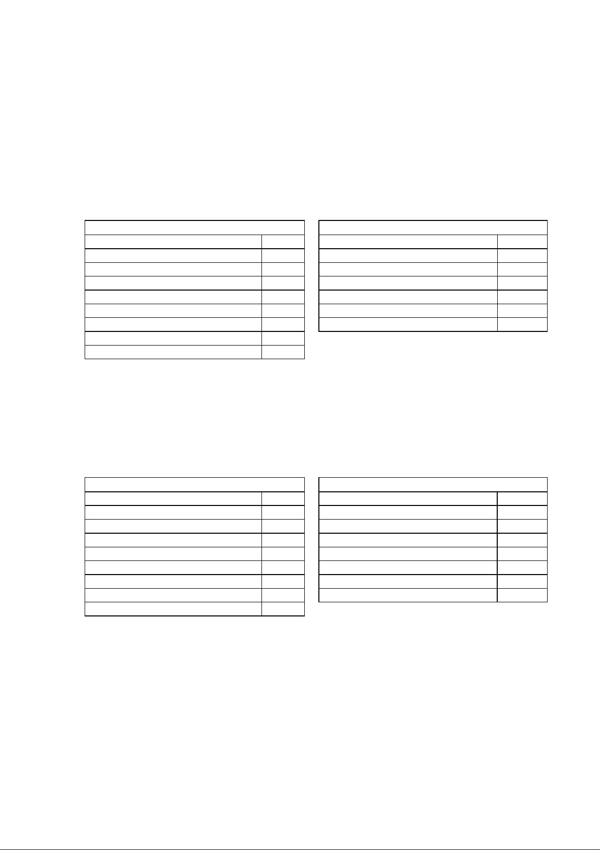
The general format for the transmission from master to slave is the following:
RANGE BYTE
Slave address 1
Function code 1
Data n
Error check (CRC-16) (low byte) 1
Error check (CRC-16) (high byte) 1
The slave detects the start of a query frame when the delay time between two characters
is greater than 3.5 T.U. (Time Unit = Time necessary to transmit one character).
ERROR CHECK(CRC-16 Cyclical Redundancy Check)
The CRC-16 value is calculated by the transmitting device. This value is appended to the
message. The receiving device recalculates a CRC-16 and compares the calculated value
to the received value. The two values must be equal.
Page 5

Page 5/59
TITLE: MODBUS/J-BUS Protocol for SSi’s- AC20 ENG. 824E REV. 1
The CRC-16 is started by first pre-loading a 16-bit register to all 1's. Then a process begins
of applying successive the bytes of the message to the current contents of the register.
Only the eight bits of data in each character are used for generating the CRC-16. Start and
stop bits, and the parity bit if one is used, do not apply to the CRC-16.
During generation of the CRC-16, each byte is exclusive ORed with the register contents.
Then the result is shifted to the right , with a zero filled into the most significant bit (MSB)
position. If the LSB was a 1, the register is then exclusive ORed with a preset, fixed value.
If the LSB was a 0, no exclusive OR takes place.
This process is repeated until eight shifts have been performed. After the last shift, the
next byte is exclusive ORed with the register's current value, and the process repeats for
eight more shifts as described above. The final contents of the register, after all the
characters of the message have been applied, is the CRC-16 value.
A procedure for generating a CRC-16 is:
1) Load a 16-bit register (CRC-16 register) with FFFFh (all 1's).
2) Exclusive OR the first byte of the message with the low byte of the CRC-16
register. Put the result in the CRC-16 register.
3) Shift the CRC-16 register one bit to the right (toward the LSB), zero-filling the
MSB. Extract and examine the LSB.
4) (If the LSB was 0): Repeat Step 3 (another shift).
(If the LSB was 1): Exclusive OR the CRC-16 register with the polynomial
value A001h (1010 0000 0000 0001b).
5) Repeat Steps 3 and 4 until 8 shifts have been performed. When this is done,
a complete byte will have been processed.
6) Repeat Steps 2 through 5 for the next byte of the message.
Continue doing this until all bytes have been processed.
7) The final contents of the CRC-16 register is the CRC-16 value.
When the CRC-16 (16 bytes) is transmitted in the message, the low byte
will be transmitted first, followed by the high byte
N.B. : the numerical value present in this text are expressed as:
binary value if they are followed by b
decimal value if they are not followed by any letter
hexadecimal value if they are followed by h
Page 6
Page 6/59
TITLE: MODBUS/J-BUS Protocol for SSi’s- AC20 ENG. 824E REV. 1
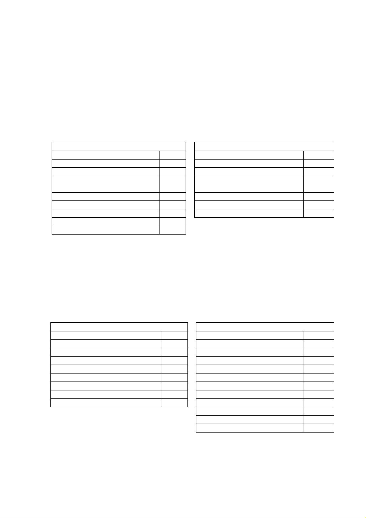
Function code 1 and 2: Bits reading
These function codes are used by the master unit to request the value of a consecutive
group of bits (max 24) which are representing the status of the slave unit.
Request from master to slave Reply from slave to master
Range Byte Range Byte
Slave address (1-255) 1 Slave address (1-255) 1
Function code (01-02) 1 Function code (01-02) 1
Bit starting address (high byte) 1 Byte count (n) 1
Bit starting address (low byte) 1 Data n
Number of bits (high byte) 1 Error check (CRC-16) (low byte) 1
Number of bits (low byte) 1 Error check (CRC-16) (high byte) 1
Error check (CRC-16) (low byte) 1
Error check (CRC-16) (high byte) 1
The “Data” field indicates the bits requested: the bit with lower address is in the bit 0 of the
first byte, the next is in the bit 1, and so on.
The eventual don’t care bits necessary to complete the last byte are equal to 0.
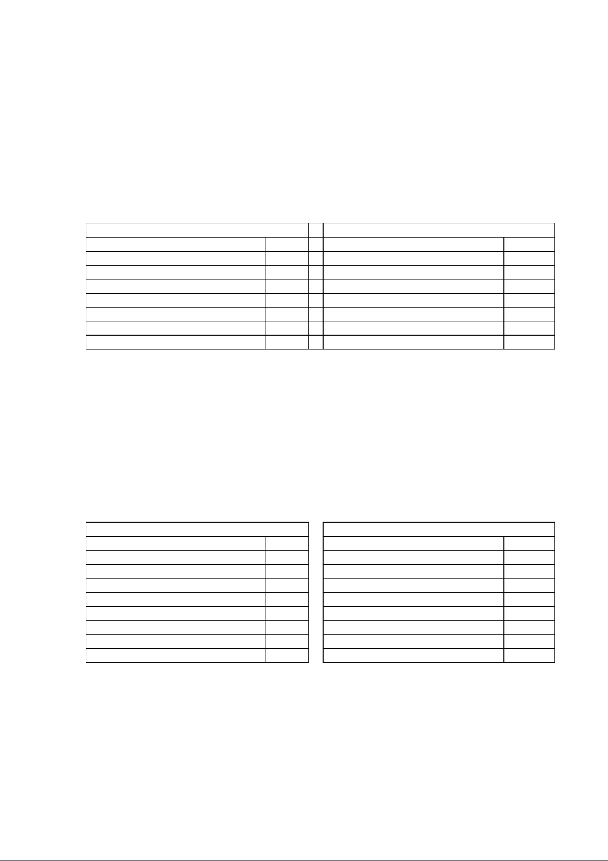
Example:
Ask to slave at address 100 (64h) the status of 14 (Eh) bits starting from bit 201 (C9h).
Request from master to slave Reply from slave to master
Range Byte Range Byte
Slave address 64h Slave address 64h
Function code 01h Function code 01h
Bit starting address (high byte) 00h Byte count 02h
Bit starting address (low byte) C9h Data A7h
Number of bits (high byte) 00h Data 04h
Number of bits (low byte) 0Eh Error check (CRC-16) (low byte) 8Eh
Error check (CRC-16) (low byte) 64h Error check (CRC-16) (high byte) 07h
Error check (CRC-16) (high byte) 05h
The 2 bytes in “Data“ field (A7h=10100111b, 04h=00000100b) mean:
bit 201 status = 1 bit 209 status = 0
bit 202 status = 1 bit 210 status = 0
bit 203 status = 1 bit 211 status = 1
bit 204 status = 0 bit 212 status = 0
bit 205 status = 0 bit 213 status = 0
bit 206 status = 1 bit 214 status = 0
bit 207 status = 0 Don’t care = 0
bit 208 status = 1 Don’t care = 0
Page 7
Page 7/59
TITLE: MODBUS/J-BUS Protocol for SSi’s- AC20 ENG. 824E REV. 1
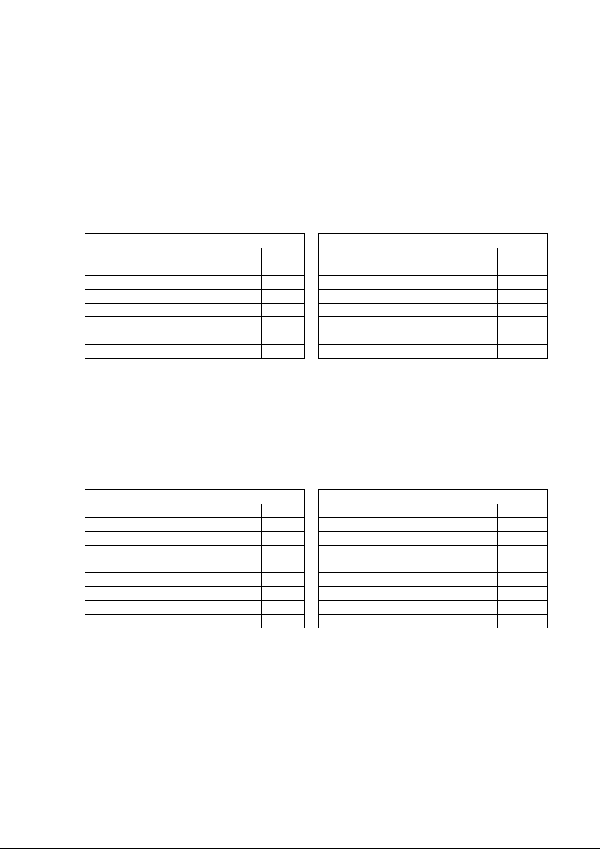
Function code 3 and 4: Words reading
These function codes are used by the master unit to read a consecutive group of words
(16 bit) which contain the value of the variable of the slave unit.
The master can require a maximum of 20 words at a time.
Request from master to slave Reply from slave to master
Range Byte Range Byte
Slave address (1-255) 1 Slave address (1-255) 1
Function code (03-04) 1 Function code (03-04) 1
Word starting address (high
1 Byte count (n) 1
byte)
Word starting address (low byte) 1 Data n
Number of word (high byte) 1 Error check (CRC-16) (low byte) 1
Number of word (low byte) 1 Error check (CRC-16) (high byte) 1
Error check (CRC-16) (low byte) 1
Error check (CRC-16) (high byte) 1
The “Data” field contains the requested words in the following format: high bytes of the first
word, low byte of the first word, high byte of the second word, and so on.
The “data” field contains 8000h for not implemented addresses or for information not
relevant in the actual device configuration.
Example:
Ask to slave at address 29 (1Dh) the value of 3 words (3h) starting from word 178 (B2h)
Request from master to slave Reply from slave to master
Range Byte Range Byte
Slave address 1Dh Slave address 1Dh
Function code 03h Function code 03h
Word starting address (high byte) 00h Byte count 06h
Word starting address (low byte) B2h Data FFh
Number of words (high byte) 00h Data 9Ch
Number of words (low byte) 03h Data 80h
Error check (CRC-16) (low byte) A7h Data 00h
Error check (CRC-16) (high byte) B0h Data 05h
Data 5Ah
Error check (CRC-16) (low byte) D7h
Error check (CRC-16) (high byte) 0Dh
The 6 bytes in “Data” field (FFh, 9Ch, 80h, 00h, 05h, 5Ah) are 3 words whose meaning is:
word 178 value = -100 (FF9Ch)
word 179 value = not implemented or not relevant (8000h)
word 180 value = 1370 (55Ah)
Page 8
Page 8/59
TITLE: MODBUS/J-BUS Protocol for SSi’s- AC20 ENG. 824E REV. 1
Function code 5: Single bit writing
By using this command, the master unit can change the state of one bit of the slave unit.
Command from master to slave Reply from slave to master
Range Byte Range Byte
Slave address (0*-255) 1 Slave address (1-255) 1
Function code (05) 1 Function code (05) 1
Bit address (high byte) 1 Bit address (high byte) 1
Bit address (low byte) 1 Bit address (low byte) 1
Data 2 Data 2
Error check (CRC-16) (low byte) 1 Error check (CRC-16) (low byte) 1
Error check (CRC-16) (high byte) 1 Error check (CRC-16) (high byte) 1
* To use the address 0, see note 1 at page 12: “Broadcast address”.
“Data” field = 0h to reset the bit
= FF00h to set the bit
Example:
Set bit 219 (DBh) of slave at address 35 (23h)
Command from master to slave Reply from slave to master
Range Byte Range Byte
Slave address 23h Slave address 23h
Function code 05h Function code 05h
Bit address (high byte) 00h Bit address (high byte) 00h
Bit address (low byte) DBh Bit address (low byte) DBh
Data FFh Data FFh
Data 00h Data 00h
Error check (CRC-16) (low byte) FAh Error check (CRC-16) (low byte) FAh
Error check (CRC-16) (high byte) 83h Error check (CRC-16) (high byte) 83h
Page 9
Page 9/59
TITLE: MODBUS/J-BUS Protocol for SSi’s- AC20 ENG. 824E REV. 1
Function code 6: Single word writing
By using this command, the master unit can change the value of one word (16 bit) of the
slave unit.
Command from master to slave Reply from slave to master
Range Byte Range Byte
Slave address (0*-255) 1 Slave address (1-255) 1
Function code (06) 1 Function code (06) 1
Word address (high byte) 1 Word address (high byte) 1
Word address (low byte) 1 Word address (low byte) n
Data 2 Data 2
Error check (CRC-16) (low byte) 1 Error check (CRC-16) (low byte) 1
Error check (CRC-16) (high byte) 1 Error check (CRC-16) (high byte) 1
* To use the address 0, see note 1 at page 12: “Broadcast address”.
The 8000h value, present in the “data” field, should be considered as a don’t care value,
that is, the value present in the device at this address will not be modified.
Example:
Set word 2006 (7D6h) of slave at address 5 (5h) with value 1250 (4E2h)
Command from master to slave Reply from slave to master
Range Byte Range Byte
Slave address 05h Slave address 05h
Function code 06h Function code 06h
Word address (high byte) 07h Word address (high byte) 07h
Word address (low byte) D6h Word address (low byte) D6h
Data 04h Data 04h
Data E2h Data E2h
Error check (CRC-16) (low byte) EAh Error check(CRC-16) (low byte) EAh
Error check (CRC-16) (high byte) 4Bh Error check (CRC-16) (high byte) 4Bh
Page 10

Page 10/59
TITLE: MODBUS/J-BUS Protocol for SSi’s- AC20 ENG. 824E REV. 1
Function code 15: Multiple bits writing
This function code is used by master unit to set/reset a consecutive group of bits (max 24).
Command from master to slave Reply from slave to master
Range Byte Range Byte
Slave address (0*-255) 1 Slave address (1-255) 1
Function code (15) 1 Function code (15) 1
Bit starting address (high byte) 1 Bit starting address (high byte) 1
Bit starting address (low byte) 1 Bit starting address (low byte) 1
Number of bits (high byte) 1 Number of bits (high byte) 1
Number of bits (low byte) 1 Number of bits (low byte) 1
Byte counter (n) 1 Error check (CRC-16) (low byte) 1
Data n Error check (CRC-16) (high byte) 1
Error check (CRC-16) (low byte) 1
Error check (CRC-16) (high byte) 1
* To use the address 0, see note 1 at page 12: “Broadcast address”.
The desired status of each bit is packed in the DATA field (1 = ON, 0 = OFF).
The status imposed for read only bits will be ignored.
The command will be processed starting from the first bit and it will be executed or not
executed depending on the actual device status.
At the first error found, the command will be aborted and the slave will answer with an
error.
Example:
Send to slave, at address 2 (2h), the following set of 9 bits:
bit 224 status = 0 (bit 0) bit 232 status = 1 (bit 0)
bit 225 status = 1 (bit 1) Don’t care = 0 (bit 1)
bit 226 status = 1 (bit 2) Don’t care = 0 (bit 2)
bit 227 status = 0 (bit 3) Don’t care = 0 (bit 3)
bit 228 status = 1 (bit 4) Don’t care = 0 (bit 4)
bit 229 status = 0 (bit 5) Don’t care = 0 (bit 5)
bit 230 status = 1 (bit 6) Don’t care = 0 (bit 6)
bit 231 status = 1 (bit 7) Don’t care = 0 (bit 7)
NOTE: 2 bytes with 9 bits and 7 don’t care bits must be sent
Command from master to slave Reply from slave to master
Range Byte Range Byte
Slave address 02h Slave address 02h
Function code 0Fh Function code 0Fh
Bit starting address (high byte) 00h Bit starting address (high byte) 00h
Bit starting address (low byte) E0h Bit starting address (low byte) E0h
Number of bits (high byte) 00h Number of bits (high byte) 00h
Number of bits (low byte) 09h Number of bits (low byte) 09h
Byte counter 02h Error check (CRC-16) (low byte) 94h
Data D6h Error check (CRC-16) (high byte) 08h
Data 01h
Error check (CRC-16) (low byte) 78h
Error check (CRC-16) (high byte) 4Ch
Page 11
Page 11/59
TITLE: MODBUS/J-BUS Protocol for SSi’s- AC20 ENG. 824E REV. 1
Function code 16: Multiple words writing
This function code is used by the master unit to write a consecutive group of words .
The master unit can change a maximum of 20 words at a time.
Command from master to slave Reply from slave to master
Range Byte Range Byte
Slave address (0*-255) 1 Slave address (1-255) 1
Function code (16) 1 Function code (16) 1
Word starting address (high
1 Word starting address (high byte) 1
byte)
Word starting address (low byte) 1 Word starting address (low byte) 1
Number of words (high byte) 1 Number of words (high byte) 1
Number of words (low byte) 1 Number of words (low byte) 1
Byte counter (n) 1 Error check (CRC-16) (low byte) 1
Data n Error check (CRC-16) (high byte) 1
Error check (CRC-16) (low byte) 1
Error check (CRC-16) (high byte) 1
* To use the address 0, see note 1 at page 12: “Broadcast address”.
The data imposed for read only words will be ignored.
The command will be processed starting from the first word and it will be executed or not
executed depending on the actual device status.
At the first error found, the command will be aborted and the slave will answer with an
error.
The 8000h value, present in the “data” field, should be considered as a don’t care value,
this is, the value present in the device at this address will not be modified.
Example:
Set words 139 (8Bh), 140 (8Ch), 141 (8Dh) of slave at address 10 (Ah) with 300 (12Ch),
don’t care (8000h) and 700 (2BCh) values.
Command from master to slave Reply from slave to master
Range Byte Range Byte
Slave address 0Ah Slave address 0Ah
Function code 10h Function code 10h
Word starting address(high byte) 00h Word starting address (high byte) 00h
Word starting address (low byte) 8Bh Word starting address (low byte) 8Bh
Number of words (high byte) 00h Number of words (high byte) 00h
Number of words (low byte) 03h Number of words (low byte) 03h
Byte counter 06h Error check (CRC-16) (low byte) F1h
Data 01h Error check (CRC-16) (high byte) 59h
Data 2Ch
Data 80h
Data 00h
Data 02h
Data BCh
Error check (CRC-16) (low byte) 33h
Error check (CRC-16) (high byte) 00h
Page 12

Page 12/59
TITLE: MODBUS/J-BUS Protocol for SSi’s- AC20 ENG. 824E REV. 1
NOTES:
1. “Broadcast” address
When using the writing codes (5, 6, 15 and 16) the slave address 0 is permitted: in this
case all the slaves connected accept the command but do not give any reply.
2. Words format
Every time the information transfer is performed by using 2 bytes (1 word of 16 bits), the
first byte transmitted is the most significant one. For the negative numbers the “two
complement” format is used.
3. Reply time
The slave will start to send a reply from 2 ms to 250 ms after the end of the request
detected by counting the received bytes
4. Decimal digits
The decimal point that may be present in the value is ignored.
Example:
The value 204.6 is transmitted as 2046 (07FEh)
The value -12.50 is transmitted as -1250 (FB1Eh)
5. Local/remote status
At power up, the slave will be in local mode if it was in control mode at power off. In the
other cases, it will maintain the condition it was at the power off.
In order to enable a slave to be controlled from the master, it is necessary to set the
local/remote status bit (ModBus bit 218).
For a slave to remain in remote status, it is sufficient to detect line activity.
If there is no line activity for more than 3 sec. every slave will automatically return to
local mode.
Local mode: the communication between master and slave is limited to
transferring data from slave to master without possibility of modifying
any parameter from the master itself (with the exception of the
local/remote status bit). Therefore from the local keyboard,
parameters can be displayed and modified.
Remote mode: the instrument parameters can be modified by the master. Therefore,
from the local keyboard the parameters can be only displayed but not
modified.
Page 13

Page 13/59
TITLE: MODBUS/J-BUS Protocol for SSi’s- AC20 ENG. 824E REV. 1
6. Control mode
“Control mode” indicates the normal functioning status of the device
(indicator/controller).
In control mode they are parameters (menu groups), variables and status.
The parameters (Menu groups) are represented by words only.
Bits and words represent the variables and the status.
Reading:
The parameters (menu groups) are available only if they are meaningful in the present
contest.
The variables and the status are available only if the device is in control mode and if
they are meaningful in the present contest
Writing:
All the addresses are available only if the device is in control mode, in remote mode, in
unlock condition (see note 9) and if they are meaningful in the present contest
7. Configuration mode
The configuration parameters (Menu conf.) are represented by words only.
They are available as read only if they are meaningful in the present contest
They are available as writing only if the device is in configuration mode, and they are
meaningful in the present contest
At the end of the parameters programming of a configuration menu it is opportune to
send the “end of configuration menu” command (ModBus words 3000 ÷ 3005). The
congruence of the programmed data compared with the data of the other configuration
menus is checked. In case of non compatibility, the reply will include a 1xx error
message where xx represents the number of the menus whose closure has caused the
error.
The end of the group programming is anyway automatically sent if data of a different
menu are programmed or read and if the output of the configuration mode is imposed.
To modify the configuration parameters via serial link, it is necessary to set the slave in
remote (ModBus bit 218). Then, set the slave in configuration mode (send the safety
lock combination value for configuration mode to ModBus word 347 *).
The display will show:
SEr
COnF
To return in control mode condition, send 1 to Modbus word 3051. The slave will reset
and restart in control mode condition.
Page 14

Page 14/59
TITLE: MODBUS/J-BUS Protocol for SSi’s- AC20 ENG. 824E REV. 1
8. Security code mode
The security code parameters are represented by words only.
They are always available as read.
They are available as writing only if the device is in security code mode.
To modify the security code parameters via serial link, it is necessary to set the slave in
remote (ModBus bit 218). Then, set the slave in security code mode (send the safety
lock combination value for configuration mode to ModBus word 348 *).
The display will show:
Scrt
COnF
To return in control mode condition, send 1 to ModBus word 3051. The slave will reset
and restart in control mode condition.
* If the value of safety lock combination for configuration mode is 0, all values will be
accepted. If the value is 1, no value will be accepted.
The safety lock combination is the value set at ModBus word 4000.
9. Software key for lock/unlock
Software keys can protect the modification of the parameters.
There is a key to protect the access to configuration mode and security code mode.
There is a second key to protect the modification of control mode parameters.
Once the control mode key is programmed, it is possible to decide which menus will be
protected and which menus will not be protected.
Keys management via serial link
Set the slave in remote (ModBus bit 218).
Set the slave in security code mode (send the present safety lock combination value for
configuration mode at ModBus word 348).
Set the new safety lock combination value for configuration mode at ModBus word
4000.
Set the new safety lock combination value for control mode at ModBus word 4001.
To protect control mode menus with the key, write 1 (key protected) in Modbus words
4002÷4011. Write 0 (free) if no key protection is needed.
Page 15

Page 15/59
TITLE: MODBUS/J-BUS Protocol for SSi’s- AC20 ENG. 824E REV. 1
N.B.:
Safety lock combination = 0: No security code (all parameters can always be
modified)
If safety lock combination is for control mode, ModBus
word 4002÷4011 are forced to 0.
Safety lock combination = 1: No security code (all parameters cannot be modified).
If safety lock combination is for control mode, ModBus
word 4002÷4011 are forced to 1.
Safety lock combination=2÷250: Security code for parameter protection.
In order to remove the protection for the control mode
parameters, it is necessary to write the safety lock
combination value for control mode at ModBus word
349. It is sufficient to do this once only.
In order to protect the control mode parameters, it is
necessary to write a value different from the safety
lock combination value for control mode at ModBus
word 349.
In order to modify the configuration parameters, it is
necessary to set the configuration mode by writing the
safety lock combination value for configuration mode
at ModBus word 347.
In order to modify the security code parameters, it is
necessary to set security code mode by writing the
safety lock combination value for configuration mode
at ModBus word 348.
ERROR REPLY
If the “error check” is wrong or the function code is not implemented or a buffer over flows
has been received, the slave does not send any reply to the master.
If other errors are detected in the request or command frame, or the slave cannot reply
with the requested values or it cannot accept the requested sets because it is in error
condition, the slave replies by forcing at “1” the bit 7 of the “Function code” byte followed
by an error code.
Error reply (from slave to master)
RANGE BYTE
Slave address 1
Function code (+80h) 1
Error code 1
Error check (CRC-16) 2
Page 16

Page 16/59
TITLE: MODBUS/J-BUS Protocol for SSi’s- AC20 ENG. 824E REV. 1
List of error codes
ERROR Nr. DESCRIPTION
2 Illegal data address
3 Illegal data value
9 Illegal number of data required
10 The bit or word indicated cannot be modified
50 The procedure cannot be initiated because another procedure is in pro-
gress
51 The procedure cannot be initiated because the first part of SMART
algorithm (TUNE) is in progress
52 The procedure cannot be initiated because it is not elapsed 5 minutes
from power on or from end of another procedure
53 The procedure cannot be initiated because the probe temperature is less
than 1000°F/538°
54 The procedure cannot be initiated because the probe output is less than
1000 mV
55 The procedure cannot be initiated because the probe output is unstable
(drift > 10 mV/minute)
101 Error on configuration group 1
102 Error on configuration group 2
103 Error on configuration group 3
104 Error on configuration group 4
105 Error on configuration group 5
106 Error on configuration group 6
151 Error on control mode group 1
152 Error on control mode group 2
153 Error on control mode group 3
154 Error on control mode group 4
155 Error on control mode group 5
156 Error on control mode group 6
157 Error on control mode group 7
158 Error on control mode group 8
159 Error on control mode group 9
160 Error on control mode group Hidden
200
201
202
Error on main probe input calibration (0÷1.5 V)
Error on main probe input calibration (1÷1.3 V)
Error on TC input calibration (0÷60 mV)
203 Error on CJ calibration
204
205
206
207
208
Error on auxiliary input current (0÷20 mA) calibration
Error on auxiliary input voltage (0÷5 V) calibration
Error on auxiliary input voltage (0÷10 V) calibration
Error on Out 6 (0÷20 mA output) calibration
Error on Out 7 (0÷20 mA output) calibration
Page 17

Page 17/59
TITLE: MODBUS/J-BUS Protocol for SSi’s- AC20 ENG. 824E REV. 1
On configuration error condition (101÷106), the device will replace the error message with
the requested value in the following cases:
• request of configuration mode menu addresses
• request of control mode menu addresses
• request of security code mode addresses
It will accept the following sets:
• set in remote (ModBus bit 218)
• set in configuration mode (ModBus word 347)
• set in security code mode (ModBus word 348)
• set of all of configuration addresses
• set of all of security code mode addresses
On control mode error condition (151÷160), the device will replace the error message with
the requested value in the following cases:
• request of configuration mode menu addresses
• request of control mode menu addresses
• request of security code mode addresses
It will accept the following sets:
• set in remote (ModBus bit 218)
• set in configuration mode (ModBus word 347)
• set in security code mode (ModBus word 348)
• set of all of configuration addresses
• set of all of control mode menu addresses
• load of control mode default parameters (ModBus bits 223÷232)
• set of all of security code mode addresses
On calibration error condition (200÷208), the device will replace the error message with the
requested value in the following cases:
• request of configuration mode menu addresses
• request of control mode menu addresses
• request of security code mode menu addresses
It will accept the following sets:
• set in remote (ModBus bit 218)
• set in configuration mode (ModBus word 347)
• set in security code mode (ModBus word 348)
• set of all of configuration mode addresses
• set of all of security code mode addresses
If a configuration or control mode or calibration error occurs at start up and no action is
taken, the device will reset after a 30 second time-out.
In configuration mode, the time-out will be disable.
Page 18

Page 18/59
TITLE: MODBUS/J-BUS Protocol for SSi’s- AC20 ENG. 824E REV. 1
WORDS FOR DEVICE IN CONTROL MODE - PARAMETERS
“St.Pn” - Menu group 1 - SET POINT VALUES
ADDRESS
(decimal) DEC. Display R
DESCRIPTION FIGU-
JBus Mod
Bus
139 138 Main set point
140 139 Auxiliary set point 2
141 140 Auxiliary set point 3
142 141 Auxiliary set point 4
RES
See Mbus
Word 300
See Mbus
Word 300
See Mbus
Word 300
See Mbus
Word 300
MNEM
CODE
E
A
D
(“SP”) x x
(“SP2”) x x
(“SP3”) x x
(“SP4”) x x
143 142 Carbon monoxide factor 0 (“COF”) x x
144 143 Hydrogen factor 0 (“H2F”) x x
“Alrñ” - Menu group 3 - ALARM THRESHOLD AND HYSTERESIS VALUE
ADDRESS
(decimal) DEC. Display R
DESCRIPTION FIGU-
JBus Mod
Bus
178 177 Alarm 1 threshold
179 178 Alarm 2 threshold
180 179 Alarm 3 threshold
182 181 Band alarm 1 threshold low
183 182 Band alarm 1 threshold high
184 183 Band alarm 2 threshold low
185 184 Band alarm 2 threshold high
186 185 Band alarm 3 threshold low
187 186 Band alarm 3 threshold high
192 191 Alarm 1 hysteresis
193 192 Alarm 2 hysteresis
194 193 Alarm 3 hysteresis
RES
See Mbus
Word 300
See Mbus
Word 300
See Mbus
Word 300
See Mbus
Word 300
See Mbus
Word 300
See Mbus
Word 300
See Mbus
Word 300
See Mbus
Word 300
See Mbus
Word 300
See Mbus
Word 300
See Mbus
Word 300
See Mbus
Word 300
MNEM
CODE
E
A
D
(“AL1”) x x
(“AL2”) x x
(“AL3”) x x
(“bA1.L”) x x
(“bA1.h”) x x
(“bA2.L”) x x
(“bA2.h”) x x
(“bA3.L”) x x
(“bA3.h”) x x
(“HSA1”) x x
(“HSA2”) x x
(“HSA3”) x x
W
R
I
T
E
W
R
I
T
E
Page 19

Page 19/59
TITLE: MODBUS/J-BUS Protocol for SSi’s- AC20 ENG. 824E REV. 1
WORDS FOR DEVICE IN CONTROL MODE - PARAMETERS
“Cntr” - Menu group 4 - CONTROL PARAMETERS
ADDRESS
(decimal) DEC. Display RWR
JBus Mod
Bus
DESCRIPTION FIGU-
RES
MNEM
CODE
E
A
D
149 148 Proportional band 1 (“Pb”) x x
150 149 Hysteresis for on/off control mode 1 (“HYS”) x x
151 150 Integral time (in seconds)
Note:
The value 7FFFh means that the integral
action is excluded
0 (“ti”) x x
152 151 Derivative time (in seconds) 0 (“td”) x x
153 152 Integral pre-load 1 (“IP”) x x
154 153 Relative secondary output gain 2 (“r.Gn”) x x
155 154 Dead band/overlap between main/secon-
0 (“OLAP”) x x
dary output
I
T
E
Page 20

Page 20/59
TITLE: MODBUS/J-BUS Protocol for SSi’s- AC20 ENG. 824E REV. 1
WORDS FOR DEVICE IN CONTROL MODE - PARAMETERS
“A.Ctr” - Menu group 5 - AUXILIARY CONTROL PARAMETERS
ADDRESS
(decimal) DEC. Display RWR
JBus Mod
Bus
DESCRIPTION FIGU-
RES
MNEM
CODE
E
A
D
1001 1000 Anti-reset windup 0 (“ArU”) x x
1004 1003 Main control output low limit 1 (“ñ.OLL”) x x
1005 1004 Main control output high limit 1 (“ñ.OLH”) x x
1006 1005 Main control output max rate of rise
Note:
The value 7FFFh means that no ramp limitation is imposed.
1007 1006 Proportional cycle time on main control
1 (“ñ.rñP”) x x
0 (“ñC.CY”) x x
output (in seconds)
1008 1007 Secondary control output low limit 1 (“S.OLL”) x x
1009 1008 Secondary control output high limit 1 (“S.OLH”) x x
1010 1009 Secondary control output max rate of
1 (“S.rñP”) x x
rise
Note:
The value 7FFFh means that no ramp limitation is imposed
1011 1010 Proportional cycle time on secondary
0 (“SC.CY”) x x
control output (in seconds)
1012 1011 Set point low limit
1013 1012 Set point high limit
1014 1013 Rate of change for positive set point va-
See Mbus
Word 300
See Mbus
Word 300
See Mbus
Word 300
(“rL”) x x
(“rH”) x x
(“Grd1”) x x
riation
Note:
The value 7FFFh means that the transfer
is done as a step change.
1015 1014 Rate of change for negative set point va-
See Mbus
Word 300
(“Grd2”) x x
riation
Note:
The value 7FFFh means that the transfer
is done as a step change
1017 1016 External control of auto/man function
Range:
0 = Off
1 = On
N.A. (“E.Añ”) x x
I
T
E
Page 21

Page 21/59
TITLE: MODBUS/J-BUS Protocol for SSi’s- AC20 ENG. 824E REV. 1
WORDS FOR DEVICE IN CONTROL MODE - PARAMETERS
“A.SEt” - Menu group 6 - ALARM SETTING
ADDRESS
(decimal) DEC. Display R
JBus Mod
DESCRIPTION FIGU-
RES
MNEM
CODE
Bus
1101 1100 Alarm 1 type
Range:
0 = Alarm on process variable
1 = Band alarm on process variable
2 = Deviation alarm on process variable
1102 1101 Alarm 1 configuration
Range:
0 = High alarm with automatic reset
1 = Low alarm with automatic reset
2 = High alarm with automatic reset and
acknowledge
3 = Low alarm with automatic reset and
acknowledge
4 = High alarm with manual reset
5 = Low alarm with manual reset
1103 1102 Alarm 1 action
Range:
0 = Rev
1 = Dir
1104 1103 Alarm 1 standby function
Range:
0 = Off
1 = On
1105 1104 Alarm 2 type
Note:
See “Alarm 1 type”
1106 1105 Alarm 2 configuration
Note:
See “Alarm 1 configuration”
1107 1106 Alarm 2 action
Range:
0 = Rev
1 = Dir
1108 1107 Alarm 2 standby function
Range:
0 = Off
1 = On
N.A. (“A1.tP”) x x
N.A. (“A1.Cn”) x x
N.A. (“A1.Ac”) x x
N.A. (“A1.St”) x x
N.A. (“A2.tP”) x x
N.A. (“A2.Cn”) x x
N.A. (“A2.Ac”) x x
N.A. (“A2.St”) x x
W
R
E
A
D
I
T
E
Page 22

Page 22/59
TITLE: MODBUS/J-BUS Protocol for SSi’s- AC20 ENG. 824E REV. 1
WORDS FOR DEVICE IN CONTROL MODE - PARAMETERS
“A.SEt” - Menu group 6 - ALARM SETTING
ADDRESS
(decimal) DEC. Display R
JBus Mod
DESCRIPTION FIGU-
RES
MNEM
CODE
Bus
1109 1108 Alarm 3 type
Note:
See “Alarm 1 type”
1110 1109 Alarm 3 configuration
Note:
See “Alarm 1 configuration”
1111 1110 Alarm 3 action
Range:
0 = Rev
1 = Dir
1112 1111 Alarm 3 standby function
Range:
0 = Off
1 = On
N.A. (“A3.tP”) x x
N.A. (“A3.Cn”) x x
N.A. (“A3.Ac”) x x
N.A. (“A3.St”) x x
W
R
E
A
D
I
T
E
Page 23

Page 23/59
TITLE: MODBUS/J-BUS Protocol for SSi’s- AC20 ENG. 824E REV. 1
WORDS FOR DEVICE IN CONTROL MODE - PARAMETERS
“Sr.Ln” - Menu group 7 - SERIAL LINK PARAMETERS
ADDRESS
(decimal) DEC. Display RWR
DESCRIPTION FIGU-
JBus Mod
Bus
527 526 Serial interface protocol
Range:
0 = No serial interface
1 = Modbus
2 = Jbus
Note:
The new data will be activated after the
de-vice answer
528 527 Serial link device address
Note:
The new data will be activated after the
de-vice answer
529 528 Baud rate for serial link
Range:
0 = 600 Baud
1 = 1200 Baud
2 = 2400 Baud
3 = 4800 Baud
4 = 9600 Baud
5 = 19200 Baud
Note:
The new data will be activated after the
de-vice answer
530 529 Byte format for serial link
Range:
0 = 8 bits + even parity
1 = 8 bits + odd parity
2 = 8 bits without parity
Note:
The new data will be activated after the
de-vice answer
RES
N.A. (“S.L.Pr”) x x
N.A. (“S.L.Ad”) x x
N.A. (“S.L.bd”) x x
N.A. (“S.L.bF”) x x
MNEM
CODE
E
A
D
I
T
E
Page 24

Page 24/59
TITLE: MODBUS/J-BUS Protocol for SSi’s- AC20 ENG. 824E REV. 1
WORDS FOR DEVICE IN CONTROL MODE - PARAMETERS
“tiñE” - Menu group 8 - TIMERS SETTING
ADDRESS
(decimal) DEC. Display R
JBus Mod
Bus
DESCRIPTION FIGU-
RES
MNEM
CODE
E
A
D
1301 1300 Timer for burn-off (in seconds) 0 (“t.bOF”) x x
1302 1301 Timer for purge (in seconds) 0 (“t.PrG”) x x
1303 1302 Timer for automatic burn-off interval (in
0 (“bF.tr”) x x
minutes)
Note:
The value 7FFFh means that no time
interval is imposed
1304 1303 Timer for probe test interval (in minutes)
Note:
The value 7FFFh means that no time
interval is imposed
1305 1304 Time lasting to beginning of burn-off
0 (“Pb.tr”) x x
0 (“bF.ñn”) x
procedure (in minutes)
Note:
The value 7FFFh means that no time
interval is imposed
1306 1305 Time lasting to beginning of probe test
0 (“Pb.ñn”) x
procedure (in minutes)
Note:
The value 7FFFh means that no time
interval is imposed
W
R
I
T
E
Page 25

Page 25/59
TITLE: MODBUS/J-BUS Protocol for SSi’s- AC20 ENG. 824E REV. 1
WORDS FOR DEVICE IN CONTROL MODE - PARAMETERS
“Hidn” - Menu group hidden - SMART LIMIT VALUE
ADDRESS
(decimal) DEC. Display R
JBus Mod
DESCRIPTION FIGU-
RES
MNEM
CODE
Bus
1201 1200 Min value of proportional band calculated
1 (“Pb.Lo”) x x
by the smart algorithm
1202 1201 Max value of proportional band cal-
1 (“Pb.Hi”) x x
culated by the smart algorithm
1203 1202 Min value of integral time value cal-
0 (“ti.Lo”) x x
culated by the smart algorithm (in seconds)
1204 1203 Max value of integral time value cal-
0 (“ti.Hi”) x x
culated by the smart algorithm (in seconds)
1205 1204 Relative secondary output gain cal-
N.A. (“rG.CL”) x x
culated by the smart algorithm
Range:
0 = Off
1 = On
W
R
E
A
D
I
T
E
Page 26

Page 26/59
TITLE: MODBUS/J-BUS Protocol for SSi’s- AC20 ENG. 824E REV. 1
WORDS FOR DEVICE IN CONTROL MODE - NON PARAMETERS
ADDRESS
(decimal) DEC. Display R
JBus Mod
DESCRIPTION FIGU-
RES
MNEM
CODE
Bus
114 113 Status led alarm 1
Range:
0 = Off
1 = On
2 = Flashing (only for alarm)
115 114 Status led alarm 2
Range:
0 = Off
1 = On
2 = Flashing (only for alarm)
116 115 Status led alarm 3
Range:
0 = Off
1 = On
2 = Flashing (only for alarm)
120 119 Variation on alarm status
Note:
Alarm status information is on D8:
(1 for entrance, 0 for exit)
Number of alarm is on low byte (D2-D0)
121 120 Manufactured trade mark
Value:
50 (32h)
122 121 Device identification code
Note:
Nr. of software revision x 100 + identification code (43)
123 122 Probe sensor mV value
Note:
When an error is detected on measure,
the “Data field” contains one of these error
codes:
30004 (7534h) = Under-range
30005 (7535h) = Over-range
30050 (7562h) = Error on internal auto zero
30051 (7563h) = Error on internal zero integrator
124 123 Carbon potential value
Note:
When an error is detected on measure,
the “Data field” contains one of these error
codes:
30050 (7562h) = Error on internal auto zero
30051 (7563h) = Error on internal zero-
integrator
N.A. x
N.A. x
N.A. x
N.A. x
N.A. x
N.A. x
0 x
2 x
W
R
E
A
D
I
T
E
Page 27

Page 27/59
TITLE: MODBUS/J-BUS Protocol for SSi’s- AC20 ENG. 824E REV. 1
WORDS FOR DEVICE IN CONTROL MODE - NON PARAMETERS
ADDRESS
(decimal) DEC. Display R
JBus Mod
DESCRIPTION FIGU-
RES
MNEM
CODE
Bus
125 124 Dew point value (Value in Celsius or
0 x
Fahrenheit as configured at Mbus word
2003)
Note:
When an error is detected on measure,
the “Data field” contains one of these error
codes:
30050 (7562h) = Error on internal auto zero
30051 (7563h) = Error on internal zero-
integrator
126 125 Probe temperature value (Value in Cel-
0 x
sius or Fahrenheit as configured at Mbus
word 2003)
Note:
When an error is detected on measure,
the “Data field” contains one of these error
codes:
30002 (7532h) = Input open
30004 (7534h) = Under-range
30005 (7535h) = Over-range
30014 (753Eh) = Error on reference junc tion (t.a.<-25°C or
t.a. >75°C)
30050 (7562h) = Error on internal auto zero
30051 (7563h) = Error on internal zero-
integrator
127 126 Carbon monoxide measured value
Note:
When an error is detected on measure,
the “Data field” contains one of these error
codes:
30049 (7561h) = Out of range
30050 (7562h) = Error on internal auto zero
30051 (7563h) = Error on internal zero-
integrator
0 x
128 127 Probe resistor value (in Kilo Ohm) 2 x
129 128 Probe response time (in seconds) 1 x
130 129 Probe temperature at last probe test (Va-
0 x
lue in Celsius or Fahrenheit as configured at Mbus word 2003)
W
R
E
A
D
I
T
E
Page 28

Page 28/59
TITLE: MODBUS/J-BUS Protocol for SSi’s- AC20 ENG. 824E REV. 1
WORDS FOR DEVICE IN CONTROL MODE - NON PARAMETERS
ADDRESS
(decimal) DEC. Display R
JBus Mod
Bus
DESCRIPTION FIGU-
RES
MNEM
CODE
E
A
D
131 130 Main control output value 1 x x
132 131 Secondary control output value 1 x x
133 132 Pid out value 1 x x
134 133 Main control output display value
135 134 Secondary control output display value
136 135 Device status mode
Range:
0 = Control mode
1 = Control mode with error E.130
2 = Control mode with error E.140
3 = Burn-off procedure in progress
4 = Purge procedure in progress
5 = Probe test procedure in progress
6 = Configuration mode
7 = Security code mode
Note:
For E.130/E.140 errors, see Technical
specifications Eng. 247E
The error is reset when read if device is in
remote state
137 136 Type of operative set point
Range:
0 = The set point utilized is a value set by
serial link (“Operative Set Point
Value”)
1 = Main set point
2 = Auxiliary set point 2
3 = Auxiliary set point 3
4 = Auxiliary set point 4
138 137 Operative set point value
Note:
It is utilized by the device for the PID as
well as for the SMART algorithms.
Any change will not be influenced by the
gradient mechanism. This set point value
is not going to be stored in Earom and it
will be lost at power down.
301 300 Decimal number relative to primary
See Mbus
word 301
See Mbus
word 302
(ñ.xxx) x
(S.xxx) x
N.A. x
N.A. x
See Mbus
word 300
N.A. x
x x
control variable
302 301 Decimal number relative to main control
N.A. x
output in engineering units
303 302 Decimal number relative to secondary
N.A. x
control output in engineering units
W
R
I
T
E
Page 29

Page 29/59
TITLE: MODBUS/J-BUS Protocol for SSi’s- AC20 ENG. 824E REV. 1
WORDS FOR DEVICE IN CONTROL MODE - NON PARAMETERS
ADDRESS
(decimal) DEC. Display R
JBus Mod
DESCRIPTION FIGU-
RES
MNEM
CODE
Bus
348 347 Code for enable configuration mode
Range :
Reading: 0 = Configuration mode
unlocked
1 = Configuration mode always
locked
2 = Configuration mode locked
by software key
Writing: 0-250
Note:
See Note 7 at page 13
349 348 Code for enable security code mode
Range :
Reading:0 = Security code mode unlocked
1 = Security code mode always
locked
2 = Security code mode locked
by software key
Writing: 0-250
Note:
See Note 8 at page 14
350 349 Code for lock/unlock control parameters
Range :
Reading: 0 = Parameters always
unlocked
1 = Parameters always locked
2 = Parameters can be locked
by software key:
Parameters locked
3 = Parameters can be locked
by software key:
Parameters unlocked.
Writing: 0-250
351 350 Lock/unlock status group hidden
Note:
See “Code For Lock/Unlock Control Para-
meters”
352 351 Lock/unlock status group 1
Note:
See “Code For Lock/Unlock Control Para-
meters”
353 352 Lock/unlock status group 2
Note:
See “Code For Lock/Unlock Control Para-
meters”
N.A. x x
N.A. x x
N.A. x x
N.A. x
N.A. x
N.A. x
W
R
E
A
D
I
T
E
Page 30

Page 30/59
TITLE: MODBUS/J-BUS Protocol for SSi’s- AC20 ENG. 824E REV. 1
WORDS FOR DEVICE IN CONTROL MODE - NON PARAMETERS
ADDRESS
(decimal) DEC. Display R
JBus Mod
DESCRIPTION FIGU-
RES
MNEM
CODE
Bus
354 353 Lock/unlock status group 3
Note:
See “Code For Lock/Unlock Control Para-
meters”
355 354 Lock/unlock status group 4
Note:
See “Code For Lock/Unlock Control Para-
meters”
356 355 Lock/unlock status group 5
Note:
See “Code For Lock/Unlock Control Para-
meters”
357 356 Lock/unlock status group 6
Note:
See “Code For Lock/Unlock Control Para-
meters”
358 357 Lock/unlock status group 7
Note:
See “Code For Lock/Unlock Control Para-
meters”
359 358 Lock/unlock status group 8
Note:
See “Code For Lock/Unlock Control Para-
meters”
360 359 Lock/unlock status group 9
Note:
See “Code For Lock/Unlock Control Para-
meters”
N.A. x
N.A. x
N.A. x
N.A. x
N.A. x
N.A. x
N.A. x
W
R
E
A
D
I
T
E
Page 31

Page 31/59
TITLE: MODBUS/J-BUS Protocol for SSi’s- AC20 ENG. 824E REV. 1
BITS FOR DEVICE IN CONTROL MODE
ADDRESS
(decimal) Display R
DESCRIPTION MNEM
JBus Mod
CODE
Bus
201 200 Logic level of external contact Dig1
Range:
0 = Logic level 0
1 = Logic level 1
202 201 Logic level of external contact Dig2
Range:
0 = Logic level 0
1 = Logic level 1
203 202 Logic level of external contact Dig3
Range:
0 = Logic level 0
1 = Logic level 1
205 204 Status relay alarm 1
Range:
0 = Off
1 = On
206 205 Status relay alarm 2
Range:
0 = Off
1 = On
207 206 Status relay alarm 3
Range:
0 = Off
1 = On
211 210 Unsolicited request flag general
Range:
0 = No Parameters change is occurred
1 = Parameters change is occurred
Note:
The bit is set also to signal the start up.
Changes produced by serial link will not be
flaged
The bit resets after reading
W
R
E
A
D
I
T
E
x
x
x
x
x
x
x
Page 32

Page 32/59
TITLE: MODBUS/J-BUS Protocol for SSi’s- AC20 ENG. 824E REV. 1
BITS FOR DEVICE IN CONTROL MODE
ADDRESS
(decimal) Display R
DESCRIPTION MNEM
JBus Mod
Bus
212 211 Status tune
Range:
0 = No tune
1 = Tune
213 212 Status adaptive
Range:
0 = No adaptive
1 = Adaptive
214 213 Lock/unlock status
Range:
0 = Unlock device
1 = Lock device
Note:
See also ModBus word 349
CODE
E
A
D
x
x
x
217 216 Start probe test procedure x
218 217 Start burn-off procedure x
219 218 Local/remote device status
Range:
0 = Device in local
1 = Device in remote
220 219 Auto/manual function
Range:
0 = Auto
1 = Manual
222 221 Smart enable/disable
Range:
0 = Disable
1 = Enable
Note:
Reading, this bit is logical OR between Tune
(ModBus bit 211) and Adaptive status
(ModBus bit 212)
223 222 Manual reset/acknowledge of an alarm
(“Sñrt”) x x
(“ñ.Rst”) x
x x
x x
condition
Range:
0 = No operation
1 = Reset alarm
224 223 Load default control parameters value
Range:
0 = No operation
1 = Load default
Note:
The command is accepted only if “Smart”
(ModBus bit 221) is not active.
The default value of group 7 (Serial link parameters) are not loaded.
W
R
I
T
E
x
Page 33

Page 33/59
TITLE: MODBUS/J-BUS Protocol for SSi’s- AC20 ENG. 824E REV. 1
BITS FOR DEVICE IN CONTROL MODE
ADDRESS
(decimal) Display R
DESCRIPTION MNEM
JBus Mod
CODE
Bus
225 224 Load default data for group hidden
Range:
0 = No operation
1 = Load default
226 225 Load default data for group 1
Range:
0 = No operation
1 = Load default
228 227 Load default data for group 3
Range:
0 = No operation
1 = Load default
229 228 Load default data for group 4
Range:
0 = No operation
1 = Load default
Note:
The command is accepted only if “Smart”
(ModBus bit 221) is not active
230 229 Load default data for group 5
Range:
0 = No operation
1 = Load default
231 230 Load default data for group 6
Range:
0 = No operation
1 = Load default
232 231 Load default data for group 7
Range:
0 = No operation
1 = Load default
Note:
The new data will be activated after the device answer
233 232 Load default data for group 8
Range:
0 = No operation
1 = Load default
234 233 De-energized all 10 auxiliary outputs
Range:
0 = No operation
1 = De-energized relays
W
R
E
A
D
I
T
E
x
x
x
x
x
x
x
x
x
Page 34

Page 34/59
TITLE: MODBUS/J-BUS Protocol for SSi’s- AC20 ENG. 824E REV. 1
BITS FOR DEVICE IN CONTROL MODE
ADDRESS
(decimal) Display R
DESCRIPTION MNEM
JBus Mod
CODE
Bus
250 249 Unsolicited request flag for probe test data
Range:
0 = No change on probe test data
1 = The probe test is terminated and new
data are available
251 250 Unsolicited request flag group hidden
Range:
0 = No Parameters change is occurred
1 = Parameters change is occurred
Note:
Changes produced by serial link will not be
flaged. The bit resets after reading
252 251 Unsolicited request flag group 1
Note:
See “Unsolicited Request Flag Group Hidden”
253 252 Unsolicited request flag group 2
Range:
0 = No status change is occurred
1 = Status change is occurred
Note:
The information of group 2 are on Modbus
bits 211, 212, 221
254 253 Unsolicited request flag group 3
Note:
See “Unsolicited Request Flag Group Hidden”
255 254 Unsolicited request flag group 4
Note:
See “Unsolicited Request Flag Group Hidden”
256 255 Unsolicited request flag group 5
Note:
See “Unsolicited Request Flag Group Hidden”
257 256 Unsolicited request flag group 6
Note:
See “Unsolicited Request Flag Group Hidden”
258 257 Unsolicited request flag group 7
Note:
See “Unsolicited Request Flag Group Hidden”
259 258 Unsolicited request flag group 8
Note:
See “Unsolicited Request Flag Group Hidden”
260 259 Unsolicited request flag group 9
Range:
0 = No change on status of auxiliary output
10÷19
1 = One or more auxiliary output is changed
Note:
See “Unsolicited Request Flag Group Hidden”
W
R
E
A
D
I
T
E
x
x
x
x
x
x
x
x
x
x
x
Page 35

Page 35/59
TITLE: MODBUS/J-BUS Protocol for SSi’s- AC20 ENG. 824E REV. 1
BITS FOR DEVICE IN CONTROL MODE
ADDRESS
(decimal) LED R
DESCRIPTION MNEM
JBus Mod
CODE
Bus
301 300 Status auxiliary input 1
Range:
0 = Open
1 = Closed
302 301 Status auxiliary input 2
Range:
0 = Open
1 = Closed
303 302 Status auxiliary input 3
Range:
0 = Open
1 = Closed
304 303 Status auxiliary input 4
Range:
0 = Open
1 = Closed
305 304 Status auxiliary input 5
Range:
0 = Open
1 = Closed
306 305 Status auxiliary input 6
Range:
0 = Open
1 = Closed
307 306 Status auxiliary input 7
Range:
0 = Open
1 = Closed
308 307 Status auxiliary input 8
Range:
0 = Open
1 = Closed
(“IN1”) x
(“IN2”) x
(“IN3”) x
(“IN4”) x
(“IN5”) x
(“IN6”) x
(“IN7”) x
(“IN8”) x
W
R
E
A
D
I
T
E
Page 36

Page 36/59
TITLE: MODBUS/J-BUS Protocol for SSi’s- AC20 ENG. 824E REV. 1
BITS FOR DEVICE IN CONTROL MODE
ADDRESS
(decimal) Display R
DESCRIPTION MNEM
JBus Mod
CODE
Bus
311 310 Status auxiliary output 10
Range:
0 = OFF
1 = ON
312 311 Status auxiliary output 11
Range:
0 = OFF
1 = ON
313 312 Status auxiliary output 12
Range:
0 = OFF
1 = ON
314 313 Status auxiliary output 13
Range:
0 = OFF
1 = ON
315 314 Status auxiliary output 14
Range:
0 = OFF
1 = ON
316 315 Status auxiliary output 15
Range:
0 = OFF
1 = ON
317 316 Status auxiliary output 16
Range:
0 = OFF
1 = ON
318 317 Status auxiliary output 17
Range:
0 = OFF
1 = ON
319 318 Status auxiliary output 18
Range:
0 = OFF
1 = ON
320 319 Status auxiliary output 19
Range:
0 = OFF
1 = ON
(“OU.10”) x x
(“OU.11”) x x
(“OU.12”) x x
(“OU.13”) x x
(“OU.14”) x x
(“OU.15”) x x
(“OU.16”) x x
(“OU.17”) x x
(“OU.18”) x x
(“OU.19”) x x
W
R
E
A
D
I
T
E
Page 37

Page 37/59
TITLE: MODBUS/J-BUS Protocol for SSi’s- AC20 ENG. 824E REV. 1
WORDS FOR DEVICE IN CONFIGURATION MODE - PARAMETERS
“Inpt.” - Menu Conf. 1 - MAIN/AUXILIARY INPUT CONFIGURATION
ADDRESS
(decimal) DEC. Display RWR
DESCRIPTION FIGU-
JBus Mod
Bus
2001 2000 Line frequency
Range:
0 = 50 Hz
1 = 60 Hz
2002 2001 Primary variable selection
Range:
0 = Carbon potential as primary control
variable (the span limits are 0.00
to 2.00)
1 = Dew point as primary control variable
(the span limits are -100 to 100°F or
-75 to 40°C)
2 = Sensor output in mV as primary
control variable (the span limits are 0
to 1500 mV)
2003 2002 Time constant for filter on probe sensor
RES
N.A. (“Ln.Fr”) x x
N.A. (“PV.SL”) x x
0 (“Pb.FL”) x x
MNEM
CODE
E
A
D
input (in seconds)
2004 2003 Input type and range value for
N.A. (“tP.In”) x x
temperature input
Range:
1 = TC K From -100 to 1370 °C
2 = TC S From - 50 to 1760 °C
3 = TC R From - 50 to 1760 °C
4 = TC K From -150 to 2500 °F
5 = TC S From - 60 to 3200 °F
6 = TC R From - 60 to 3200 °F
2005 2004 Temperature input offset adjustment
0 (“OFSt”) x x
(Value in Celsius or Fahrenheit as configured at Mbus word 2003)
2006 2005 Time constant for filter on temperature
0 (“tP.FL”) x x
value (in seconds)
2007 2006 Auxiliary input function for carbon mono-
N.A. (“CO.In”) x x
xide measurement
Range:
0 = Input not used
1 = Input used for CO measurement
2008 2007 Auxiliary input type
Range:
0 = 0÷20 mA
1 = 4÷20 mA
2 = 0÷5 V
3 = 1÷5 V
4 = 0÷10 V
5 = 2÷10 V
N.A. (“CO.tP”) x x
I
T
E
Page 38

Page 38/59
TITLE: MODBUS/J-BUS Protocol for SSi’s- AC20 ENG. 824E REV. 1
WORDS FOR DEVICE IN CONFIGURATION MODE - PARAMETERS
“Out.” - Menu Conf. 2 - OUTPUT CONFIGURATION
ADDRESS
(Decimal) DEC. Display RWR
DESCRIPTION FIGU-
Jbus Mod
Bus
2101 2100 Out 1 function
Range:
0 = Output not used
1 = Time proportional main control output
2 = Time proportional secondary control
output
3 = Output used as alarm 1 output
2102 2101 Out 2 function
Range:
0 = Output not used
1 = Time proportional main control output
2 = Time proportional secondary control
output
3 = Output used as alarm 2 output
2103 2102 Out 3 function
Range:
0 = Output not used
1 = Time proportional main control output
2 = Time proportional secondary control
output
3 = Output used as alarm 3 output
2107 2106 Out 6 function
Range:
0 = Output not used
1 = Linear main control output
2 = Linear secondary control output
3 = Process variable retransmission
4 = Operative set point retransmission
2108 2107 Out 6 range
Range:
0 = 0 ÷ 20 mA
1 = 4 ÷ 20 mA
2109 2108 Retransmission low scale range value for
RES
N.A. ("O1.Fn") x x
N.A. ("O2.Fn") x x
N.A. ("O3.Fn") x x
N.A. ("O6.Fn") x x
N.A. ("O6.rn") x x
See Mbus
word 300
MNEM
CODE
E
A
D
(“O6.Lr”) x x
Out 6
2110 2109 Retransmission high scale range value
See Mbus
word 300
(“O6.Hr”) x x
for Out 6
2111 2110 Time constant for filter on Out 6 analog
0 (“O6.FL”) x x
retransmission value (in seconds)
I
T
E
Page 39

Page 39/59
TITLE: MODBUS/J-BUS Protocol for SSi’s- AC20 ENG. 824E REV. 1
WORDS FOR DEVICE IN CONFIGURATION MODE - PARAMETERS
“Out.” - Menu Conf. 2 - OUTPUT CONFIGURATION
ADDRESS
(Decimal) DEC. Display RWR
DESCRIPTION FIGU-
Jbus Mod
Bus
2112 2111 Out 7 function
Range:
0 = Output not used
1 = Linear main control output
2 = Linear secondary control output
3 = Process variable retransmission
4 = Operative set point retransmission
2113 2112 Out 7 range
Range:
0 = 0 ÷ 20 mA
1 = 4 ÷ 20 mA
2114 2113 Retransmission low scale range value for
RES
N.A. (“O7.Fn”) x x
N.A. (“O7.rn”) x x
See Mbus
word 300
MNEM
CODE
E
A
D
(“O7.Lr”) x x
Out 7
2115 2114 Retransmission high scale range value
See Mbus
word 300
(“O7.Hr”) x x
for Out 7
2116 2115 Time constant for filter on Out 7 analog
0 (“O7.FL”) x x
retransmission value (in seconds)
I
T
E
Page 40

Page 40/59
TITLE: MODBUS/J-BUS Protocol for SSi’s- AC20 ENG. 824E REV. 1
WORDS FOR DEVICE IN CONFIGURATION MODE - PARAMETERS
“C.Cn.” - Menu Conf. 3 - CONTROL OUTPUT CONFIGURATION
ADDRESS
(Decimal) DEC. Display RWR
DESCRIPTION FIGU-
Jbus Mod
Bus
2206 2205 Main control output conditioning
Range
0 = The control output is calculated by the
PID
1 = The control output is complemented
(100-PID calculated value)
2207 2206 Main control output scaleable for display
RES
N.A. (“ñC.Cn”) x x
N.A. (“ñ.SCL”) x x
MNEM
CODE
E
A
D
in eng. unit
Range:
0 = Scaleable is not required
1 = Scaleable is required
2208 2207 Decimal point position for main control
N.A. (“ñC.dP”) x x
output display in eng. unit
Range:
0 = No decimal figure
1 = One decimal figure
2 = Two decimal figure
2209 2208 Low scale range value for main control
output display in eng. unit
2210 2209 High scale range value for main control
output display in eng. unit
2211 2210 Main control output auxiliary conditioning
Range:
0 = The functions described in the note
are applied “Before” of the “Main
control output conditioning” stage
1 = The functions described in the note
are applied “After” of the “Main control
output conditioning” stage
Note:
a - Control output limiter
b - Control output max rate of rise
c - Control output display value
2212 2211 Secondary control output conditioning
Note:
See “Main control output conditioning”
2213 2212 Secondary control output scaleable for
See Mbus
word 301
or 2207
See Mbus
word 301
or 2207
N.A.
(“ñC.E.L.”)
(“ñC.E.H.”)
(“ñC.A.C.”)
x x
x x
x x
N.A. (“SC.Cn.”) x x
N.A. (“S.SCL”) x x
display in eng. unit
Range:
0 = Scaleable is not required
1 = Scaleable is required
I
T
E
Page 41

Page 41/59
TITLE: MODBUS/J-BUS Protocol for SSi’s- AC20 ENG. 824E REV. 1
WORDS FOR DEVICE IN CONFIGURATION MODE – PARAMETERS
“C.Cn.” – Menu Conf. 3 – CONTROL OUTPUT CONFIGURATION
ADDRESS
(Decimal) DEC. Display RWR
DESCRIPTION FIGU-
Jbus Mod
Bus
2214 2213 Decimal point position for secondary
RES
N.A. (“SC.dP”) x x
MNEM
CODE
E
A
D
control output display in eng. Unit
Range:
0 = No decimal figure
1 = One decimal figure
2 = Two decimal figure
2215 2214 Low scale range value for secondary
control output display in eng. unit
2216 2215 High scale range value for secondary
control output display in eng. unit
2217 2216 Secondary control output auxiliary condi-
See Mbus
word 302
or 2213
See Mbus
word 302
or 2213
(“SC.E.L.”) x x
(“SC.E.H”) x x
N.A. (“SC.A.C”) x x
tioning
0 = The functions described in the note
are applied “Before” of the “Secondary
control output conditioning” stage
1 = The functions described in the note
are applied “After” of the “Secondary
control output conditioning” stage
Note:
a - Control output limiter
b - Control output max rate of rise
c - Control output display value
I
T
E
Page 42

Page 42/59
TITLE: MODBUS/J-BUS Protocol for SSi’s- AC20 ENG. 824E REV. 1
WORDS FOR DEVICE IN CONFIGURATION MODE - PARAMETERS
“AC.Cn.” - Menu conf. 4 - AUXILIARY CONTROL OUTPUT CONFIGURATION
ADDRESS
(decimal) DEC. Display R
JBus Mod
DESCRIPTION FIGU-
RES
MNEM
CODE
Bus
2301 2300 Smart function
Range
0 = Smart function disable
1 = Smart function may be enabled
2302 2301 Control action type
Range
0 = The process is controlled by PID
actions
1 = The process is controlled by PI actions
2303 2302 Manual function
Range
0 = Manual function disabled
1 = Manual function enabled
2304 2303 Output value for transfer from auto to
N.A. (“Sñ.Fn”) x x
N.A. (“Cn.tP”) x x
N.A. (“ñAn.F”) x x
1 (“Añ.UL”) x x
manual
Note:
The value 7FFFh means that the transfer
from auto to manual is bumpless
2305 2304 Manual/auto transfer type
Range
0 = Bumpless balance transfer
1 = Bumpless balanceless transfer
2306 2305 Device status at start up
Range
0 = It starts always in auto mode
1 = It starts always in manual mode with
power output set to 0
2 = It starts in the same way it was left
prior to power shut down (if in manual
mode the power output is set to 0)
3 = It starts in the same way it was left
prior to power shut down (if in manual
mode the power output will be the last
value prior to power shut down)
N.A. (“ñ.A.t.t”) x x
N.A. (“St.Fn”) x x
W
R
E
A
D
I
T
E
Page 43

Page 43/59
TITLE: MODBUS/J-BUS Protocol for SSi’s- AC20 ENG. 824E REV. 1
WORDS FOR DEVICE IN CONFIGURATION MODE - PARAMETERS
“In.Ot.” - Menu conf. 5 - DIGITAL INPUT/OUTPUT CONFIGURATION
ADDRESS
(decimal) DEC. Display R
JBus Mod
DESCRIPTION FIGU-
RES
MNEM
CODE
Bus
2401 2400 External contact “DIG1” function
Range:
0 = Input contact not used
1 = Input contact used for SP/SP2
auxiliary set point selection
2 = Input contact used for SP3/SP4
auxiliary set point selection
3 = Input contact used for Auto/Manual
selection
4 = Input contact used for output limiter
activation
5 = Input contact used to reset
(acknowledge) alarm
2402 2401 External contact “DIG1” logic level
Range:
0 = The input is at logic level “1” when
contact is open
1 = The input is at logic level “1” when
contact is closed
2403 2402 External contact “DIG2” function
Note:
See “External contact “DIG1” function”
2404 2403 External contact “DIG2” logic level
Note:
See “External contact “DIG1” logic level“
2406 2405 External contact “DIG3” logic level
Note:
See “External contact “DIG1” logic level“
N.A. (“d1.Fn”) x x
N.A. (“d1.St”) x x
N.A. (“d2.Fn”) x x
N.A. (“d2.St”) x x
N.A. (“d3.St”) x x
W
R
E
A
D
I
T
E
Page 44

Page 44/59
TITLE: MODBUS/J-BUS Protocol for SSi’s- AC20 ENG. 824E REV. 1
WORDS FOR DEVICE IN CONFIGURATION MODE - PARAMETERS
“Othr.” - Menu conf. 6 - OTHER CONFIGURATION PARAMETER
ADDRESS
(decimal) DEC. Display RWR
JBus Mod
DESCRIPTION FIGU-
RES
MNEM
CODE
Bus
2501 2500 Green bar-graph selection
Range:
0 = On bar-graph the process variable
value is shown
1 = On bar-graph the deviation error is
shown
2502 2501 Orange bar-graph selection
Range:
0 = On bar-graph the operative set-point
value is shown
1 = On bar-graph the process output value
is shown
2503 2502 Bar-graph low scale range value
2504 2503 Bar-graph high scale range value
2505 2504 Deviation bar-graph resolution
Range:
0 = 1 digit per segment
1 = 2 digits per segment
2 = 5 digits per segment
3 = 10 digits per segment
4 = 20 digits per segment
5 = 50 digits per segment
2507 2506 Set point display type
Range:
0 = the final set point will be shown
1 = the operative set point will be shown
2508 2507 Temperature threshold activation
Range:
0 = NO
1 = YES
2510 2509 Time-out selection
Range:
0 = 10 seconds time-out
1 = 30 seconds time-out
N.A. (“G.brG”) x x
N.A. (“O.brG”) x x
See Mbus
word 300
See Mbus
word 300
(“brG.L”) x x
(“brG.H”) x x
N.A. (“brG.d”) x x
N.A. (“SP.dS”) x x
N.A. (“t.t.Ac) x x
N.A. (“t.out”) x x
E
I
A
T
D
E
Page 45

Page 45/59
TITLE: MODBUS/J-BUS Protocol for SSi’s- AC20 ENG. 824E REV. 1
WORDS FOR DEVICE IN CONFIGURATION MODE - NON PARAMETERS
ADDRESS
(decimal) DEC. Display RWR
DESCRIPTION FIGU-
JBus Mod
Bus
3001 3000 The end of configuration menu 1
Range:
1 = end of configuration menu 1
3002 3001 The end of configuration menu 2
Range:
1 = end of configuration menu 2
3003 3002 The end of configuration menu 3
Range:
1 = end of configuration menu 3
3004 3003 The end of configuration menu 4
Range:
1 = end of configuration menu 4
3005 3004 The end of configuration menu 5
Range:
1 = end of configuration menu 5
3006 3005 The end of configuration menu 6
Range:
1 = end of configuration menu 6
3051 3050 Load default configuration value
Range:
1 = Load default TB1=European table
2 = Load default TB2=American table
3052 3051 Enable control mode
Range:
1 = Enable control mode
RES
N.A. x
N.A. x
N.A. x
N.A. x
N.A. x
N.A. x
N.A. (TB1/TB2) x
N.A. x
MNEM
CODE
E
A
D
I
T
E
Page 46

Page 46/59
TITLE: MODBUS/J-BUS Protocol for SSi’s- AC20 ENG. 824E REV. 1
WORDS FOR DEVICE IN SECURITY CODE MODE
ADDRESS
(decimal) DEC. Display RWR
DESCRIPTION FIGU-
JBus Mod
Bus
4001 4000 Safety lock combination for configuration
RES
MNEM
CODE
E
A
D
x x
mode
Range :
Reading: 0 = No parameters protection
1 = Parameters always
protected
2 = Parameters protected by
software key
Writing: 0-250
4002 4001 Safety lock combination for control mode
Range :
Reading: 0 = No parameters protection
1 = Parameters always
protected
2 = Parameters protected by
software key
Writing: 0-250
4003 4002 Group hidden protected
Range :
0 = Group non protected
1 = Group protected
4004 4003 Group 1 protected
Range :
0 = Group non protected
1 = Group protected
4005 4004 Group 2 protected
Range :
0 = Group non protected
1 = Group protected
4006 4005 Group 3 protected
Range :
0 = Group non protected
1 = Group protected
4007 4006 Group 4 protected
Range :
0 = Group non protected
1 = Group protected
4008 4007 Group 5 protected
Range :
0 = Group non protected
1 = Group protected
4009 4008 Group 6 protected
Range :
0 = Group non protected
1 = Group protected
4010 4009 Group 7 protected
Range :
0 = Group non protected
1 = Group protected
x x
x x
x x
x x
x x
x x
x x
x x
x x
I
T
E
Page 47

Page 47/59
TITLE: MODBUS/J-BUS Protocol for SSi’s- AC20 ENG. 824E REV. 1
WORDS FOR DEVICE IN SECURITY CODE MODE
ADDRESS
(decimal) DEC. Display RWR
DESCRIPTION FIGU-
JBus Mod
Bus
4011 4010 Group 8 protected
Range :
0 = Group non protected
1 = Group protected
4012 4011 Group 9 protected
Range :
0 = Group non protected
1 = Group protected
RES
MNEM
CODE
E
A
D
x x
x x
I
T
E
Page 48

Page 48/59
TITLE: MODBUS/J-BUS Protocol for SSi’s- AC20 ENG. 824E REV. 1
INDEX, DIVIDED IN FAMILIES AND GROUPS, OF MODBUS WORDS
Words For Device In Control Mode - Parameters
Menu group 1 – Set point values
138 - Main set point ("SP") page 18
139 - Auxiliary set point 2 (“SP2”) page 18
140 - Auxiliary set point 3 (“SP3”) page 18
141 - Auxiliary set point 4 (“SP4”) page 18
142 - Carbon monoxide factor ("COF") page 18
143 - Hydrogen factor ("H2F") page 18
Menu group 3 - Alarm threshold and hysteresis value
177 - Alarm 1 threshold ("AL1") page 18
178 - Alarm 2 threshold ("AL2") page 18
179 - Alarm 3 threshold ("AL3") page 18
181 - Band alarm 1 threshold low ("bA1.L") page 18
182 - Band alarm 1 threshold high ("bA1.h") page 18
183 - Band alarm 2 threshold low ("bA2.L") page 18
184 - Band alarm 2 threshold high ("bA2.h") page 18
185 - Band alarm 3 threshold low ("bA3.L") page 18
186 - Band alarm 3 threshold high ("bA3.h") page 18
191 - Alarm 1 hysteresis ("HSA1") page 18
192 - Alarm 2 hysteresis ("HSA2") page 18
193 - Alarm 3 hysteresis ("HSA3") page 18
Menu group 4 - Control parameters
148 - Proportional band ("Pb") page 19
149 - Hysteresis for on/off control mode ("HYS") page 19
150 - Integral time ("ti") page 19
151 - Derivative time ("td") page 19
152 - Integral pre-load ("IP") page 19
153 - Relative secondary output gain ("r.Gn") page 19
154 - Dead band/overlap between main/secondary output ("OLAP") page 19
Menu group 5 - Auxiliary control parameters
1000 - Anti-reset windup ("ArU") page 20
1003 - Main control output low limit ("ñ.OLL") page 20
1004 - Main control output high limit ("ñ.OLH") page 20
1005 - Main control output max rate of rise ("ñ.rñP") page 20
1006 - Proportional cycle time on main control output ("ñC.CY") page 20
1007 - Secondary control output low limit ("S.OLL") page 20
1008 - Secondary control output high limit ("S.OLH") page 20
1009 - Secondary control output max rate of rise ("S.rñP") page 20
1010 - Proportional cycle time on secondary control output ("SC.CY") page 20
1011 - Set point low limit ("rL") page 20
1012 - Set point high limit ("rH") page 20
1013 - Rate of change for positive set point variation ("Grd1") page 20
1014 - Rate of change for negative set point variation ("Grd2") page 20
1016 - External control of auto/man function ("E.Añ") page 20
Page 49

Page 49/59
TITLE: MODBUS/J-BUS Protocol for SSi’s- AC20 ENG. 824E REV. 1
Menu group 6 - Alarm setting
1100 - Alarm 1 type ("A1.tP") page 21
1101 - Alarm 1 configuration ("A1.Cn") page 21
1102 - Alarm 1 action ("A1.Ac") page 21
1103 - Alarm 1 standby function ("A1.St") page 21
1104 - Alarm 2 type ("A2.tP") page 21
1105 - Alarm 2 configuration ("A2.Cn") page 21
1106 - Alarm 2 action ("A2.Ac") page 21
1107 - Alarm 2 standby function ("A2.St") page 21
1108 - Alarm 3 type ("A3.tP") page 22
1109 - Alarm 3 configuration ("A3.Cn") page 22
1110 - Alarm 3 action ("A3.Ac") page 22
1111 - Alarm 3 standby function ("A3.St") page 22
Menu group 7 - Serial link parameter
526 - Serial interface protocol ("S.L.Pr") page 23
527 - Serial link device address ("S.L.Ad") page 23
528 - Baud rate for serial link ("S.L.bd") page 23
529 - Byte format for serial link ("S.L.bF") page 23
Menu group 8 - Timers setting
1300 - Timer for burn-off (“t.bOF”) page 24
1301 - Timer for purge (“t.PrG”) page 24
1302 - Timer for automatic burn-off interval (“bF.tr”) page 24
1303 - Timer for probe test interval (“Pb.tr”) page 24
1304 - Time lasting to beginning of burn-off procedure (“bF.ñn”) page 24
1305 - Time lasting to beginning of probe test procedure (“Pb.ñn”) page 24
Menu group hidden - Smart limit value
1200 - Min value of proportional band calculated by the smart algorithm (“Pb.Lo") page 25
1201 - Max value of proportional band calculated by the smart algorithm ("Pb.Hi") page 25
1202 - Min value of integral time value calculated by the smart algorithm ("ti.Lo") page 25
1203 - Max value of integral time value calculated by the smart algorithm ("ti.Hi") page 25
1204 - Relative secondary output gain calculated by the smart algorithm ("rG.CL") page 25
Words For Device In Control Mode - Non Parameters
113 - Status led alarm 1 page 26
114 - Status led alarm 2 page 26
115 - Status led alarm 3 page 26
119 - Variation on alarm status page 26
120 - Manufactured trade mark page 26
121 - Device identification code page 26
122 - Probe sensor mV value page 26
123 - Carbon potential value page 26
124 - Dew point value page 27
125 - Probe temperature value page 27
126 - Carbon monoxide measured value page 27
127 - Probe resistor value page 27
128 - Probe response time page 27
129 - Probe temperature at last probe test page 27
130 - Main control output value page 28
131 - Secondary control output value page 28
Page 50

Page 50/59
TITLE: MODBUS/J-BUS Protocol for SSi’s- AC20 ENG. 824E REV. 1
Words For Device In Control Mode - Non Parameters
132 - Pid out value page 28
133 - Main control output display value (ñ.xxx) page 28
134 - Secondary control output display value (S.xxx) page 28
135 - Device status mode page 28
136 - Type of operative set point page 28
137 - Operative set point value page 28
300 - Decimals relative to primary control variable page 28
301 - Decimals relative to main control output in engineering units page 28
302 - Decimals relative to secondary control output in engineering units page 28
347 - Code for enable configuration mode page 29
348 - Code for enable security code mode page 29
349 - Code for lock/unlock control parameters page 29
350 - Lock/unlock status group hidden page 29
351 - Lock/unlock status group 1 page 29
352 - Lock/unlock status group 2 page 29
353 - Lock/unlock status group 3 page 30
354 - Lock/unlock status group 4 page 30
355 - Lock/unlock status group 5 page 30
356 - Lock/unlock status group 6 page 30
357 - Lock/unlock status group 7 page 30
358 - Lock/unlock status group 8 page 30
359 - Lock/unlock status group 9 page 30
Words For Device In Configuration Mode - Parameters
Menu conf. 1 - Main/auxiliary input configuration
2000 - Line frequency ("Ln.Fr") page 37
2001 - Primary variable selection ("PV.SL") page 37
2002 - Time constant for filter on probe sensor input ("Pb.FL") page 37
2003 - Input type and range value for temperature input ("tP.In") page 37
2004 - Temperature input offset adjustment ("OFSt") page 37
2005 - Time constant for filter on temperature value ("tP.FL") page 37
2006 - Auxiliary input function for carbon monoxide measurement ("CO.In") page 37
2007 - Auxiliary input type ("CO.tP") page 37
Menu conf. 2 - Output configuration
2100 - Out 1 function (“O1.Fn”) page 38
2101 - Out 2 function (“O2.Fn”) page 38
2102 - Out 3 function (“O3.Fn”) page 38
2106 - Out 6 function (“O6.Fn”) page 38
2107 - Out 6 range (“O6.rn”) page 38
2108 - Retransmission low scale range value for Out 6 ("O6.Lr") page 38
2109 - Retransmission high scale range value for Out 6 ("O6.Hr") page 38
2110 - Time constant for filter on Out 6 analog retransmission value ("O6.FL") page 38
2111 - Out 7 function ("O7.Fn") page 39
2112 - Out 7 range ("O7.rn") page 39
2113 - Retransmission low scale range value for Out 7 ("O7.Lr") page 39
2114 - Retransmission high scale range value for Out 7 ("O7.Hr") page 39
2115 - Time constant for filter on Out 7 analog retransmission value ("O7.FL") page 39
Page 51

Page 51/59
TITLE: MODBUS/J-BUS Protocol for SSi’s- AC20 ENG. 824E REV. 1
Menu conf. 3 - Control output configuration
2205 - Main control output conditioning ("ñC.Cn") page 40
2206 - Main control output scaleable for display in e.u. ("ñ.SCL") page 40
2207 - Decimal point position for main control output display in e.u. ("ñC.dP") page 40
2208 - Low scale range value for main control output display in e.u. ("ñC.E.L") page 40
2209 - High scale range value for main control output display in e.u. ("ñC.E.H") page 40
2210 - Main control output auxiliary conditioning ("ñC.A.C")
page 40
2211 - Secondary control output conditioning ("SC.Cn") page 40
2212 - Secondary control output scaleable for display in e.u. ("S.SCL") page 40
2213 - Decimal point position for secondary control output display in e.u. ("SC.dP") page 41
2214 - Low scale range value for secondary control output display in e. u. ("SC.E.L") page 41
2215 - High scale range value for secondary control output display in e. u. ("SC.E.H") page 41
2216 - Secondary control output auxiliary conditioning ("SC.A.C") page 41
Menu conf. 4 - Auxiliary control output configuration
2300 - Smart function ("Sñ.Fn") page 42
2301 - Control action type (“Cn.Tp”) page 42
2302 - Manual function ("ñAn.F") page 42
2303 - Output value for transfer from auto to manual ("Añ.UL") page 42
2304 - Manual/auto transfer type ("ñ.A.t.t") page 42
2305 - Device status at start up ("St.Fn") page 42
Menu conf. 5 - Digital input/output configuration
2400 - External contact "DIG1" function ("d1.Fn") page 43
2401 - External contact "DIG1" logic level ("d1.St") page 43
2402 - External contact "DIG2" function ("d2.Fn") page 43
2403 - External contact "DIG2" logic level ("d2.St") page 43
2405 - External contact "DIG3" logic level ("d3.St") page 43
Menu conf. 6 - Other configuration parameters
2500 - Green bar-graph selection ("G.brG") page 44
2501 - Orange bar-graph selection ("O.brG") page 44
2502 - Bar-graph low scale range value ("brG.L") page 44
2503 - Bar-graph high scale range value ("brG.H") page 44
2504 - Deviation bar-graph resolution ("brG.d") page 44
2506 - Set point display type ("SP.dS") page 44
2507 - Temperature threshold activation (“t.t.Ac”) page 44
2509 - Time-out selection ("t.out") page 44
Words For Device In Configuration Mode - Non Parameters
3000 - The end of configuration menu 1 page 45
3001 - The end of configuration menu 2 page 45
3002 - The end of configuration menu 3 page 45
3003 - The end of configuration menu 4 page 45
3004 - The end of configuration menu 5 page 45
3005 - The end of configuration menu 6 page 45
3050 - Load default configuration value page 45
3051 - Enable control mode page 45
Page 52

Page 52/59
TITLE: MODBUS/J-BUS Protocol for SSi’s- AC20 ENG. 824E REV. 1
Words For Device In Security Code Mode
4000 - Safety lock combination for configuration mode page 46
4001 - Safety lock combination for control mode page 46
4002 - Group hidden protected page 46
4003 - Group 1 protected page 46
4004 - Group 2 protected page 46
4005 - Group 3 protected page 46
4006 - Group 4 protected page 46
4007 - Group 5 protected page 46
4008 - Group 6 protected page 46
4009 - Group 7 protected page 46
4010 - Group 8 protected page 47
4011 - Group 9 protected page 47
Page 53

Page 53/59
TITLE: MODBUS/J-BUS Protocol for SSi’s- AC20 ENG. 824E REV. 1
INDEX OF MODBUS BITS
Bits For Device In Control Mode
200 - Logic level of external contact DIG1 page 31
201 - Logic level of external contact DIG2 page 31
202 - Logic level of external contact DIG3 page 31
204 - Status relay alarm 1 page 31
205 - Status relay alarm 2 page 31
206 - Status relay alarm 3 page 31
210 - Unsolicited request flag general page 31
211 - Status tune page 32
212 - Status adaptive page 32
213 - Lock/unlock status page 32
216 - Start probe test procedure page 32
217 - Start burn-off procedure page 32
218 - Local/remote device status page 32
219 - Auto/manual function page 32
221 - Smart enable/disable ("Sñrt") page 32
222 - Manual reset/acknowledge of an alarm condition ("n.rSt") page 32
223 - Load default control parameters value page 32
224 - Load default group hidden
page 33
225 - Load default group 1 page 33
227 - Load default group 3 page 33
228 - Load default group 4 page 33
229 - Load default group 5 page 33
230 - Load default group 6 page 33
231 - Load default group 7 page 33
232 - Load default group 8 page 33
233 - De-energized all 10 auxiliary outputs page 33
249 - Unsolicited request flag for probe test data
page 34
250 - Unsolicited request flag group hidden page 34
251 - Unsolicited request flag group 1 page 34
252 - Unsolicited request flag group 2 page 34
253 - Unsolicited request flag group 3 page 34
254 - Unsolicited request flag group 4 page 34
255 - Unsolicited request flag group 5 page 34
256 - Unsolicited request flag group 6 page 34
257 - Unsolicited request flag group 7 page 34
258 - Unsolicited request flag group 8 page 34
259 - Unsolicited request flag group 9 page 34
300 - Status auxiliary input 1 page 35
301 - Status auxiliary input 2 page 35
302 - Status auxiliary input 3 page 35
303 - Status auxiliary input 4 page 35
304 - Status auxiliary input 5 page 35
305 - Status auxiliary input 6 page 35
306 - Status auxiliary input 7 page 35
307 - Status auxiliary input 8 page 35
310 - Status auxiliary output 10 page 36
311 - Status auxiliary output 11 page 36
312 - Status auxiliary output 12 page 36
313 - Status auxiliary output 13 page 36
314 - Status auxiliary output 14 page 36
315 - Status auxiliary output 15 page 36
316 - Status auxiliary output 16 page 36
317 - Status auxiliary output 17 page 36
Page 54

Page 54/59
TITLE: MODBUS/J-BUS Protocol for SSi’s- AC20 ENG. 824E REV. 1
318 - Status auxiliary output 18 page 36
319 - Status auxiliary output 19 page 36
Page 55

Page 55/59
TITLE: MODBUS/J-BUS Protocol for SSi’s- AC20 ENG. 824E REV. 1
INDEX, IN ASCENDING ORDER, OF MODBUS WORDS
113 - Status led alarm 1 page 26
114 - Status led alarm 2 page 26
115 - Status led alarm 3 page 26
119 - Variation on alarm status page 26
120 - Manufactured trade mark page 26
121 - Device identification code
page 26
122 - Probe sensor mV value page 26
123 - Carbon potential value page 26
124 - Dew point value page 27
125 - Probe temperature value page 27
126 - Carbon monoxide measure value
page 27
127 - Probe resistor value page 27
128 - Probe response time page 27
129 - Probe temperature at last probe test page 27
130 - Main control output value
page 28
131 - Secondary control output value page 28
132 - Pid out value page 28
133 - Main control output display value (ñ.xxx) page 28
134 - Secondary control output display value (S.xxx) page 28
135 - Device status mode page 28
136 - Type of operative set point page 28
137 - Operative set point value page 28
138 - Main set point ("SP") page 18
139 - Auxiliary set point 2 (“SP2”) page 18
140 - Auxiliary set point 3 (“SP3”) page 18
141 - Auxiliary set point 4 (“SP4”) page 18
142 - Carbon monoxide factor (“COF”) page 18
143 - Hydrogen factor (“H2F”) page 18
148 - Proportional band ("Pb") page 19
149 - Hysteresis for on/off control mode ("HYS") page 19
150 - Integral time ("ti") page 19
151 - Derivative time ("td") page 19
152 - Integral pre-load ("IP") page 19
153 - Relative secondary output gain ("r.Gn") page 19
154 - Dead band/overlap between main/secondary output ("OLAP") page 19
177 - Alarm 1 threshold ("AL1") page 18
178 - Alarm 2 threshold ("AL2") page 18
179 - Alarm 3 threshold ("AL3") page 18
181 - Band alarm 1 threshold low ("bA1.L") page 18
182 - Band alarm 1 threshold high ("bA1.h") page 18
183 - Band alarm 2 threshold low ("bA2.L") page 18
184 - Band alarm 2 threshold high ("bA2.h") page 18
185 - Band alarm 3 threshold low ("bA3.L") page 18
186 - Band alarm 3 threshold high ("bA3.h") page 18
191 - Alarm 1 hysteresis ("HSA1") page 18
192 - Alarm 2 hysteresis ("HSA2") page 18
193 - Alarm 3 hysteresis ("HSA3") page 18
Page 56

Page 56/59
TITLE: MODBUS/J-BUS Protocol for SSi’s- AC20 ENG. 824E REV. 1
300 - Decimal number relative to primary control variable page 28
301 - Decimal number relative to main control output in engineering units
page 28
302 - Decimal number relative to secondary control output in eng. units page 28
347 - Code for enable configuration mode page 29
348 - Code for enable security code mode page 29
349 - Code for lock/unlock control parameters page 29
350 - Lock/unlock status group hidden page 29
351 - Lock/unlock status group 1 page 29
352 - Lock/unlock status group 2 page 29
353 - Lock/unlock status group 3 page 30
354 - Lock/unlock status group 4 page 30
355 - Lock/unlock status group 5 page 30
356 - Lock/unlock status group 6 page 30
357 - Lock/unlock status group 7 page 30
358 - Lock/unlock status group 8 page 30
359 - Lock/unlock status group 9 page 30
526 - Serial interface protocol ("S.L.Pr") page 23
527 - Serial link device address ("S.L.Ad") page 23
528 - Baud rate for serial link ("S.L.bd") page 23
529 - Byte format for serial link ("S.L.bF") page 23
1000 - Anti-reset windup ("ArU") page 20
1003 - Main control output low limit ("ñ.OLL") page 20
1004 - Main control output high limit ("ñ.OLH") page 20
1005 - Main control output max rate of rise ("ñ.rñP") page 20
1006 - Proportional cycle time on main control output ("ñC.CY") page 20
1007 - Secondary control output low limit ("S.OLL") page 20
1008 - Secondary control output high limit ("S.OLH") page 20
1009 - Secondary control output max rate of rise ("S.rñP")
page 20
1010 - Proportional cycle time on secondary control output ("SC.CY") page 20
1011 - Set point low limit ("rL") page 20
1012 - Set point high limit ("rH") page 20
1013 - Rate of change for positive set point variation ("Grd1") page 20
1014 - Rate of change for negative set point variation ("Grd2") page 20
1016 - External control of auto/man function ("E.Añ") page 20
1100 - Alarm 1 type ("A1.tP") page 21
1101 - Alarm 1 configuration ("A1.Cn") page 21
1102 - Alarm 1 action ("A1.Ac") page 21
1103 - Alarm 1 standby function ("A1.St") page 21
1104 - Alarm 2 type ("A2.tP") page 21
1105 - Alarm 2 configuration ("A2.Cn") page 21
1106 - Alarm 2 action ("A2.Ac") page 21
1107 - Alarm 2 standby function ("A2.St") page 21
1108 - Alarm 3 type ("A3.tP") page 22
1109 - Alarm 3 configuration ("A3.Cn") page 22
1110 - Alarm 3 action ("A3.Ac") page 22
1111 - Alarm 3 standby function ("A3.St") page 22
1200 - Min value of proportional band calculated by the smart algorithm (“Pb.Lo") page 25
1201 - Max value of proportional band calculated by the smart algorithm ("Pb.Hi") page 25
1202 - Min value of integral time value calculated by the smart algorithm ("ti.Lo") page 25
1203 - Max value of integral time value calculated by the smart algorithm ("ti.Hi")
page 25
1204 - Relative secondary output gain calculation by the smart algorithm ("rG.CL") page 25
1300 - Timer for burn-off (“t.bOF”) page 24
1301 - Timer for purge (“t.PrG”) page 24
1302 - Timer for automatic burn-off interval (“bF.tr”) page 24
1303 - Timer for probe test interval (“Pb.tr”) page 24
1304 - Time lasting to beginning of burn-off procedure (“bF.ñn”) page 24
1305 - Time lasting to beginning of probe test procedure (“Pb. ñn”) page 24
Page 57

Page 57/59
TITLE: MODBUS/J-BUS Protocol for SSi’s- AC20 ENG. 824E REV. 1
2000 - Line frequency ("Ln.Fr") page 37
2001 - Input type and range value for main input ("ñ.In.t") page 37
2002 - Decimal point position for main input ("ñ.In.d") page 37
2003 - Square root extraction for main input ("ñ.In.S") page 37
2004 - Low scale range value for main input ("ñ.In.L") page 37
2005 - High scale range value for main input ("ñ.In.H") page 37
2006 - Main input offset adjustment ("OFSt") page 37
2007 - Time constant for filter on main input display value ("dS.FL") page 37
2100 - Out 1 function (“O1.Fn”) page 38
2101 - Out 2 function (“O2.Fn”) page 38
2102 - Out 3 function (“O3.Fn”) page 38
2106 - Out 6 function (“O6.Fn”) page 38
2107 - Out 6 range (“O6.rn”) page 38
2108 - Retransmission low scale range value for Out 6 ("O6.Lr") page 38
2109 - Retransmission high scale range value for Out 6 ("O6.Hr") page 38
2110 - Time constant for filter on Out 6 analog retransmission value ("O6.FL") page 38
2111 - Out 7 function ("O7.Fn") page 39
2112 - Out 7 range ("O7.rn") page 39
2113 - Retransmission low scale range value for Out 7 ("O7.Lr") page 39
2114 - Retransmission high scale range value for Out 7 ("O7.Hr") page 39
2115 - Time constant for filter on Out 7 analog retransmission value ("O7.FL") page 39
2205 - Main control output conditioning ("ñC.Cn") page 40
2206 - Main control output scaleable for display in e.u. ("ñ.SCL") page 40
2207 - Decimal point position for main control output display in e.u. ("ñC.dP") page 40
2208 - Low scale range value for main control output display in e.u. ("ñC.E.L") page 40
2209 - High scale range value for main control output display in e.u. ("ñC.E.H") page 40
2210 - Main control output auxiliary conditioning ("ñC.A.C")
page 40
2211 - Secondary control output conditioning ("SC.Cn") page 40
2212 - Secondary control output scaleable for display in e.u. ("S.SCL") page 40
2213 - Decimal point position for secondary control output display in e.u. ("SC.dP") page 41
2214 - Low scale range value for secondary control output display in e. u. ("SC.E.L") page 41
2215 - High scale range value for secondary control output display in e. u. ("SC.E.H") page 41
2216 - Secondary control output auxiliary conditioning ("SC.A.C") page 41
2300 - Smart function ("Sñ.Fn") page 42
2301 - Control action type (“Cn.Tp”) page 42
2302 - Manual function ("ñAn.F") page 42
2303 - Output value for transfer from auto to manual ("Añ.UL") page 42
2304 - Manual/auto transfer type ("ñ.A.t.t")
page 42
2305 - Device status at start up ("St.Fn") page 42
2400 - External contact "dig 1" function ("d1.Fn") page 43
2401 - External contact "dig 1" logic level ("d1.St")
page 43
2402 - External contact "dig 2" function ("d2.Fn") page 43
2403 - External contact "dig 2" logic level ("d2.St")
page 43
2405 - External contact "dig 3" logic level ("d3.St")
page 43
2500 - Green bar-graph selection ("G.brG") page 44
2501 - Orange bar-graph selection ("O.brG") page 44
2502 - Bar-graph low scale range value ("brG.L") page 44
2503 - Bar-graph high scale range value ("brG.H") page 44
2504 - Deviation bar-graph resolution ("brG.d") page 44
2506 - Set point display type ("SP.dS") page 44
2507 - Temperature threshold activation (“tt.Ac”) page 44
2509 - Time-out selection ("t.out") page 44
3000 - The end of configuration menu 1 page 45
3001 - The end of configuration menu 2 page 45
3002 - The end of configuration menu 3 page 45
Page 58

Page 58/59
TITLE: MODBUS/J-BUS Protocol for SSi’s- AC20 ENG. 824E REV. 1
3003 - The end of configuration menu 4 page 45
3004 - The end of configuration menu 5 page 45
3005 - The end of configuration menu 6 page 45
3050 - Load default configuration value page 45
3051 - Enable control mode page 45
Page 59

Page 59/59
TITLE: MODBUS/J-BUS Protocol for SSi’s- AC20 ENG. 824E REV. 1
4000 - Safety lock combination for configuration mode page 46
4001 - Safety lock combination for run time mode page 46
4002 - Group hidden protected page 46
4003 - Group 1 protected page 46
4004 - Group 2 protected page 46
4005 - Group 3 protected page 46
4006 - Group 4 protected page 46
4007 - Group 5 protected page 46
4008 - Group 6 protected page 46
4009 - Group 7 protected page 46
4010 - Group 8 protected page 47
4011 - Group 9 protected page 47
Page 60

Page 60/59
TITLE: MODBUS/J-BUS Protocol for SSi’s- AC20 ENG. 824E REV. 1
INDEX, IN ASCENDING ORDER, OF MODBUS BITS
200 - Logic level of external contact Dig1 page 31
201 - Logic level of external contact Dig2 page 31
202 - Logic level of external contact Dig3 page 31
204 - Status relay alarm 1 page 31
205 - Status relay alarm 2 page 31
206 - Status relay alarm 3 page 31
210 - Unsolicited request flag general page 31
211 - Status tune page 32
212 - Status adaptive page 32
213 - Lock/unlock status page 32
216 - Start probe test procedure page 32
217 - Start burn-off procedure page 32
218 - Local/remote device status page 32
219 - Auto/manual function page 32
221 - Smart enable/disable ("Sñrt") page 32
222 - Manual reset/acknowledge of an alarm condition ("n.rSt") page 32
223 - Load default control parameters value page 32
224 - Load default data for group hidden page 33
225 - Load default data for group 1 page 33
227 - Load default data for group 3 page 33
228 - Load default data for group 4 page 33
229 - Load default data for group 5 page 33
230 - Load default data for group 6 page 33
231 - Load default data for group 7 page 33
232 - Load default data for group 8 page 33
233 - De-energized all 10 auxiliary outputs page 33
249 - Unsolicited request flag for probe test data
page 34
250 - Unsolicited request flag group hidden page 34
251 - Unsolicited request flag group 1 page 34
252 - Unsolicited request flag group 2 page 34
253 - Unsolicited request flag group 3 page 34
254 - Unsolicited request flag group 4 page 34
255 - Unsolicited request flag group 5 page 34
256 - Unsolicited request flag group 6 page 34
257 - Unsolicited request flag group 7 page 34
258 - Unsolicited request flag group 8 page 34
259 - Unsolicited request flag group 9 page 34
300 - Status auxiliary input 1 page 35
301 - Status auxiliary input 2 page 35
302 - Status auxiliary input 3 page 35
303 - Status auxiliary input 4 page 35
304 - Status auxiliary input 5 page 35
305 - Status auxiliary input 6 page 35
306 - Status auxiliary input 7 page 35
307 - Status auxiliary input 8 page 35
310 - Status auxiliary output 10 page 36
311 - Status auxiliary output 11 page 36
312 - Status auxiliary output 12 page 36
313 - Status auxiliary output 13 page 36
314 - Status auxiliary output 14 page 36
315 - Status auxiliary output 15 page 36
316 - Status auxiliary output 16 page 36
317 - Status auxiliary output 17 page 36
318 - Status auxiliary output 18 page 36
319 - Status auxiliary output 19 page 36
Page 61

Page 61/59
TITLE: MODBUS/J-BUS Protocol for SSi’s- AC20 ENG. 824E REV. 1
Page 62

Page 62/59
TITLE: MODBUS/J-BUS Protocol for SSi’s- AC20 ENG. 824E REV. 1
Additional and specialized technical notes
- Eng.247E Technical specifications for SSi’s AC20 Atmosphere Controller
 Loading...