

Page 1

9120 Operations Manual
Super Systems Inc.
7205 Edington Drive
Cincinnati, OH 45249
513-772-0060 / 800-666-4330
Fax: 513-772-9466
www.supersystems.com
Page 2

Table of Contents
General Information .................................................................................................................................................... 3
SSi 9120 Setup ........................................................................................................................................................... 4
Step 1 – Install Configurator 2.0 on the Local Computer ............................................................................................ 4
Step 2 – Connect the SSi 9120 to a Network or Local Computer ................................................................................. 6
Step 3 – Configure Configurator 2.0 on the local computer ......................................................................................... 7
Step 4 – Complete Configurator
Step 5 – Complete Configurator
Step 6 – Complete Configurator
Step 7 – Complete Configurator
Step 8 – Complete Configurator
Step 9 – Complete Configurator
SSi 9120 Pinout Diagram ........................................................................................................................................... 20
SSi 9120 Wiring Diagram ........................................................................................................................................... 21
Section 1 – 9120 Configurator Menus ......................................................................................................................... 22
Burnoff ................................................................................................................................................................. 22
Slave Instruments .................................................................................................................................................. 23
Aux Analog Inputs ................................................................................................................................................. 24
Burnoff Setup ........................................................................................................................................................ 24
PID Loop Setup ..................................................................................................................................................... 25
Furnace Setup ....................................................................................................................................................... 27
Communications Setup........................................................................................................................................... 29
Slave Instrument Setup .......................................................................................................................................... 30
Analog Input Setup ................................................................................................................................................ 31
Analog Output Setup.............................................................................................................................................. 32
Alarm Setup .......................................................................................................................................................... 34
Calibration ............................................................................................................................................................. 36
Overview ........................................................................................................................................................... 36
Equipment needed ............................................................................................................................................. 36
Calibration Procedure ......................................................................................................................................... 37
User Calibration .................................................................................................................................................. 37
Full Calibration ................................................................................................................................................... 38
Appendix 1 – Standard Configurations for PVT Types .................................................................................................. 41
Appendix 2 – Accessing the SSi 9120 Web Page ......................................................................................................... 43
Revision History ........................................................................................................................................................ 45
Furnace Setup
Analog Input Setup
Analog Output Setup
Alarm Setup
Menu Option ...................................................................................... 9
Menu Option ............................................................................ 11
Menu Option .......................................................................... 13
Menu Option ....................................................................................... 15
Communications Setup
PID Loop Setup
Menu Option .................................................................................. 17
Menu option ........................................................................ 17
4574 - SSi 9120 Manual Rev A Page 2 Super Systems Inc
Page 3

GGeenneerraall IInnffoorrmmaattiioonn
The SSi 9120 is a single or dual loop blind controller/signal conditioning/data concentrating device that can be used in
carbon, oxygen, millivolt, SSi redundant probe, simple nitriding and universal dual loop applications. The 9120 is supplied
with Ethernet communications capability and has a limited web server for thin client control and supports ModbusTCP
host communications. Serial I/O includes two (2) RS-232 ports and three (3) RS-485 ports. As a data concentrator, the
9120 is capable of communication to SSi's analog input modules as well as up to 25 slave serial instruments and supports
host communications via Modbus over RS232 or RS485 or ModbusTCP communications.
The SSi 9120 Controller is a single or two loop device that can be configured to be used for control of:
% Carbon
Dew Point
Oxygen
Millivolt
Redundant Probe
Simple Nitrider
Dual Loop
Temperature Mode
4574 - SSi 9120 Manual Rev A Page 3 Super Systems Inc
Page 4
SSSSii 99112200 SSeettuupp
This section will explain how to set the SSi 9120 controller up. The steps required to set up the SSi 9120 through a local
computer are:
1. Install Configurator 2.0 on the local computer
2. Connect the SSi 9120 to a network or local computer
3. Configure Configurator 2.0 on the local computer
4. Complete Configurator
5. Complete Configurator
6. Complete Configurator
7. Complete Configurator
8. Complete Configurator
9. Complete Configurator
Furnace Setup
Analog Input Setup
Analog Output Setup
Alarm Setup
Communications Setup
PID Loop Setup
menu option
menu option
menu option
menu option
menu option
menu option
Step 1 – Install Configurator 2.0 on the Local Computer
Configurator 2.0 is a configuration utility developed by SSi that will allow the user to interface with an SSi instrument
directly or over a network. The installation file, ConfiguratorSetup.msi, should be included with the installation CD
provided by SSi. If this file is not on the CD, contact Super Systems at 513-772-0060.
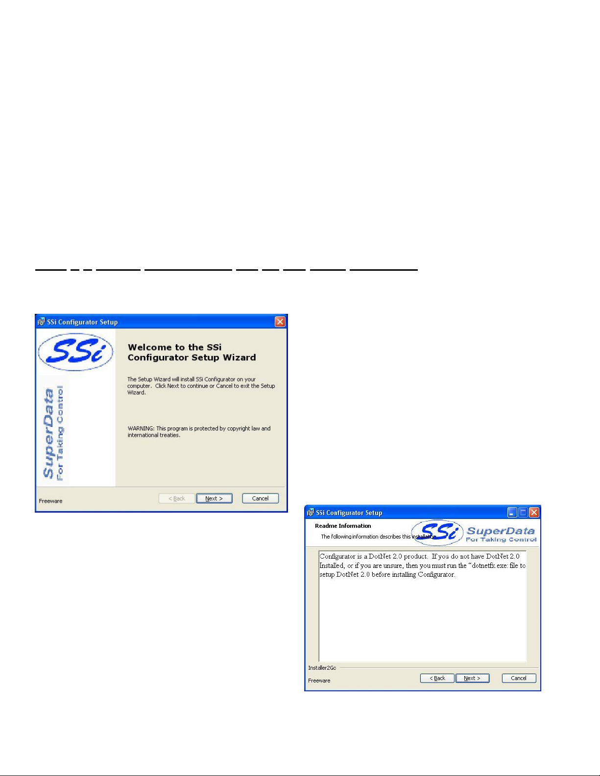
Double-click on the installation file to begin the installation
process.
The first page displayed is just for information purposes.
Click on the Next > button to move to the next page, or
press the Cancel button to cancel the installation.
The second page is a warning about Configurator 2.0.
Since Configurator 2.0 is a Microsoft .Net 2.0 product, the
local computer will have to have the .Net 2.0 framework
installed before Configurator 2.0 can be used. Click on the
Next > button to continue or the Cancel button to cancel
the installation.
4574 - SSi 9120 Manual Rev A Page 4 Super Systems Inc
Page 5

Page 3 will allow the user to select the location of the
installation. The default location is “C:\SSi\”. To change this
location, click on the Browse button and select a new location
from the dialog box that is displayed. The Disk Usage button
is a utility that will display the available hard drive space on the
local computer. Click on the Next > button to move to the
next page.
Page 4 will allow the user to review the installation settings, if
necessary. Click on the Install button to install the software.
Page 5 will display a progress bar as the installation proceeds.
Note: The installation should only take a few minutes
.
4574 - SSi 9120 Manual Rev A Page 5 Super Systems Inc
Page 6
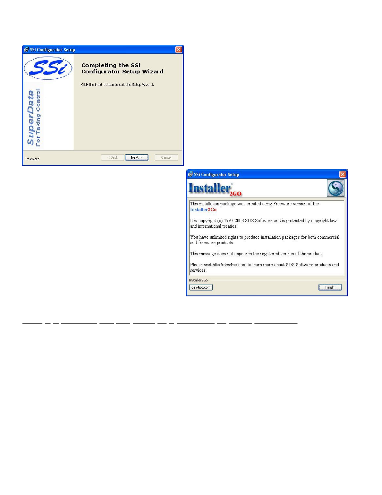
Page 7 is the informational screen about the makers of
the installation software. Click on the Finish button to
close out this screen.
Page 6 is the finishing screen, which is displayed after the
software has been installed. Click on the Next > button to
continue.
Step 2 – Connect the SSi 9120 to a Network or Local Computer
To connect the instrument to the network, through a wall port or switch, use a regular Ethernet cable. To connect the
instrument directly to a computer, use an Ethernet crossover cable. Contact your IT Department for the necessary
cables. Once the SSi 9120 is connected to a network, the Configurator 2.0 software will be able to find it during any
searches. Connecting the instrument to your network or directly to a PC is accomplished using the Ethernet port on the
instrument. If you are connecting the instrument to your network, you will need an Ethernet cable. The cable is plugged
into the instrument Ethernet plug and then other end should be plugged into a network hub. If the IP Address of the
instrument needs to be changed, this can be done through the Configurator software (see Step 3 below). If you are not
putting the instrument on the network, you should use an Ethernet crossover cable. Ethernet crossover cables are most
often used when connecting two Ethernet computers without a hub. An Ethernet crossover cable has its send and receive
wires crossed. When using a hub or switch, this is automatically done for you. With a crossover cable, you are forming a
network between the computer that you are directly plugged into and the SSi 9120. There will be some network settings
on the computer that you will have to configure for the 2 devices to communicate. The SSi 9120 will have the network
setting already setup with the following default IP address – 192.168.0.200. This can be modified through the
Configurator software.
Network settings can be found through the
operator will be given a list of the current available connection types. Using the crossover cable will require the “Local
Control Panel
in Microsoft Windows. By selecting
Network Setting
, the
4574 - SSi 9120 Manual Rev A Page 6 Super Systems Inc
Page 7
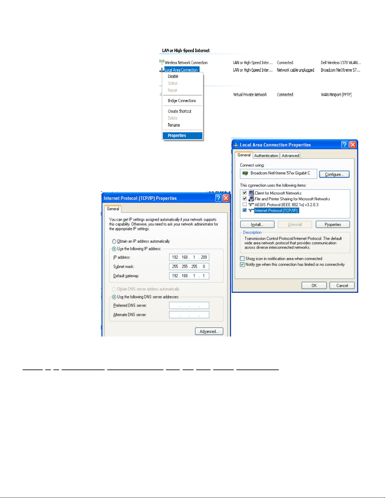
Area Connection” as seen in the diagram to be
modified. The Properties can be changed by
highlighting the connection and using the right
mouse button to click and select the
tab or by highlighting the connection and
clicking on Change setting of this connection.
Once the
screen is displayed, highlight the Internet
Protocol (TCP/IP) option. Click the Properties
button to display Internet Protocol
(TCP/IP) Properties. On the Internet Protocol
(TCP/IP) Properties tab, you will need to select
the option for Use The Following IP Address.
Enter in the following data on these fields:
IP Address: 192.168.0.209
Subnet Mask: 255.255.255.0
Default Gateway: 192.168.1.1
Note: These fields are suggestions. Contact your IT department to get a
valid IP address, Net Mask, and Gateway for the local computer.
To change the network
settings on your
computer you may need
addition information so
please refer to the
computer manual.
Local Area Connection Properties
Properties
Step 3 – Configure Configurator 2.0 on the local computer
When Configurator starts up for the first time, the user will see the main screen, which will be blank because no
instruments have been set up yet. The first step is to set up an instrument in Configurator.
4574 - SSi 9120 Manual Rev A Page 7 Super Systems Inc
Page 8

First, the user will need to log in
with administrative rights.
The user will need to be logged in
with at least administrative rights;
Supervisor rights will not allow the
user to add an instrument
four levels of rights in Configurator
are: operator, supervisor,
administrator, SSi Special. The
lock on the toolbar will let the user
know what level is currently logged
in. Operators are blue, supervisors
are gold, administrators are green,
and the SSi Special, which is used
for configuration purposes before
the unit is shipped, is red. Click on
the lock and log in with the
following information: username =
administrator, password = 2.
Note: The supervisor and
administrator passwords can be
Furnace Setup
. The lock should now
screen.
be green. Click on the
Click on the Add button to display the rest of
the screen. First, give the instrument a
name. The name can be anything the user
wants, but it is suggested that the user
makes the name descriptive. Next, select the
model from the drop-down list. Next, enter
the IP address in the “Ethernet” section and
make sure the “Ethernet” option is selected.
Note: The SSi 9120 is shipped with a default
IP address of 192.168.0.200. This is set
this way so that it will not interfere with any
other instruments/computers on the network.
Options
menu, then select
Settings
. This will display the
changed on the
menu page
System Management
Note: even if the local computer is hooked up
directly to the instrument through a crossover
cable, the IP address will still need to be
correct
to find all available SSi instruments by
clicking on the search button next to the
“Ethernet” IP address box. This will set up
Configurator for Ethernet communications.
To set it up for serial or SuperData
communications, the proper option will need to be selected and filled out. Click on the Save button to save the
information. Click on the Done button to close down this screen.
. The user can also scan the network
Note:
. The
4574 - SSi 9120 Manual Rev A Page 8 Super Systems Inc
Page 9
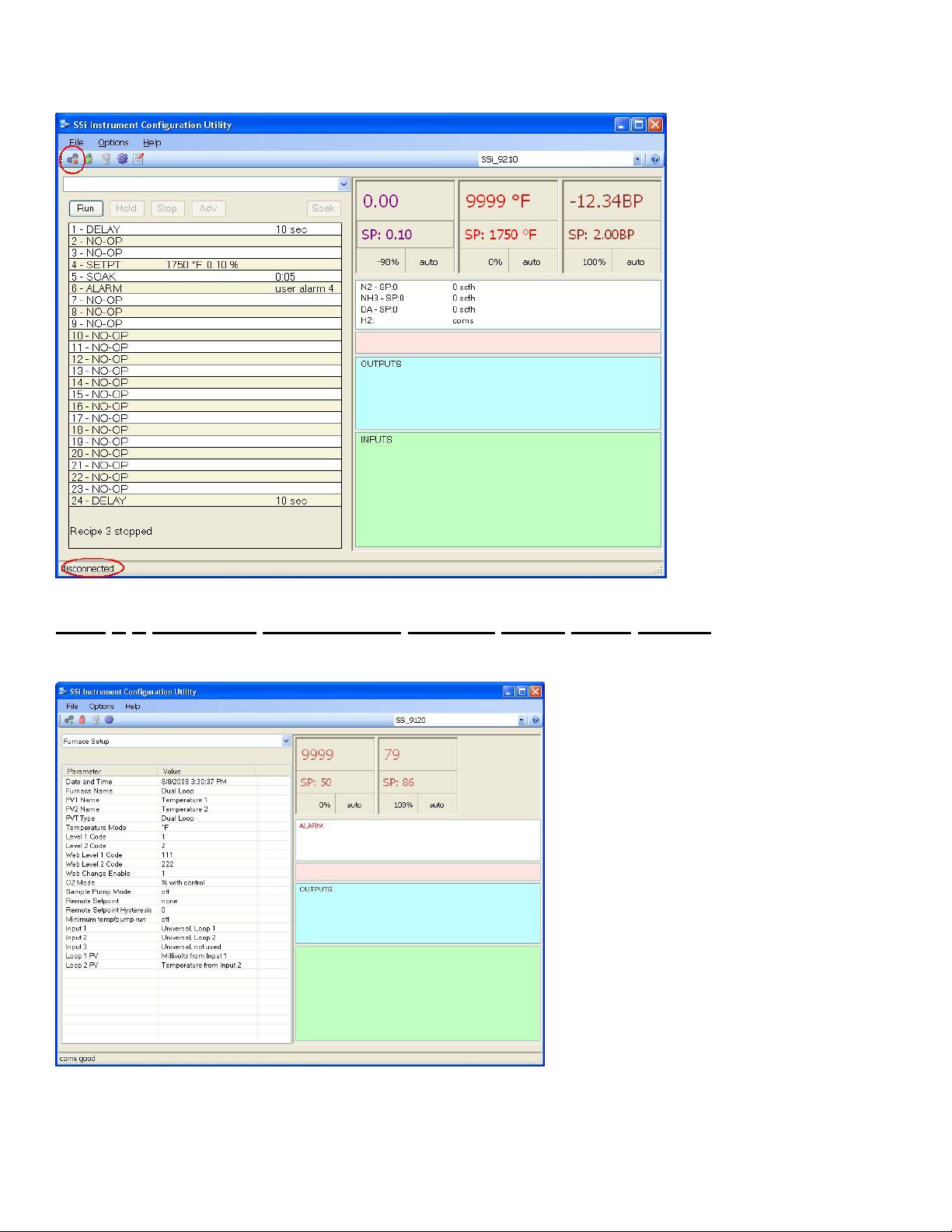
Click on the Connect button on
the left of the toolbar to
connect to the device. If the
connect button has a red
square on it, then the device is
disconnected. If the button
has a green triangle, then the
device is connected. Also, the
connection status is displayed
along the bottom of the
screen.
Once the device is connected,
the user can move on to “Step
4 - Complete Configurator
Furnace Setup
menu option”.
Step 4 – Complete Configurator
Furnace Setup
Note: This menu item is also located later in the manual under the
enter the PV’s name.
Menu Option
Section 1 – 9120 Configurator Menus
The Furnace Setup menu option is an
administrative access only option. Do not make
any adjustments on this screen without first
contacting Super Systems Inc.
Date and Time
This option will display the current date and time
on the 9120 controller. From this menu option,
the user can change the date/time
controller
Furnace Name
This value will define the name of the furnace.
Clicking on the “Value” column will bring up an
input box where the user can enter the furnace’s
name.
PV1 Name
This value will define the name of the first
process variable. Clicking on the “Value” column
will bring up an input box where the user can
.
section
on the 9120
.
4574 - SSi 9120 Manual Rev A Page 9 Super Systems Inc
Page 10

PV2 Name
This value will define the name of the second process variable. Clicking on the “Value” column will bring up an input box
where the user can enter the PV’s name.
PVT Type
The PVT type is the mode the device runs in (Carbon, Dewpoint, etc.). The mode selected determines the calculations
and scaling for the Process Variable.
performs a simple calculation based on that input
defaults to ensure all parameters have been changed to the new Process Variable (
→ Set Defaults button or FD Preserve button). Clicking on this value will display an input box with a drop-down list
from which the user can select a new PVT Type.
The values for the PVT type are:
% Carbon
Dew Point
Oxygen
Millivolt
Redundant Probe
Simple Nitrider
Dual Loop
Temperature Mode
This value determines the specific temperature scale to be used. Clicking on the value will allow the operator to change
the value. It can be either Degrees °°°°F or degrees °°°°C.
Level 1 Code
Typically, operations used by a supervisor require a level 1 code for access. When a supervisor is logged in, the lock on
the toolbar will be gold, . To change the level 1 passcode, click on the “Level 1 Code” value (range is –32768 to
32767) and an input box will be displayed where the user can select a new value.
Level 2 Code
Typically, operations used by an administrator require a level 2 code for access. When an administrator is logged in, the
lock on the toolbar will be green, . To change the level 2 passcode, click on the “Level 2 Code” value (range is –
32768 to 32767) and an input box will be displayed where the user can select a new value.
Web Level 1 Code
This value is the supervisor-level passcode for any web-based operations with the 9120 controller. Clicking on the value
will allow the operator to change the value. The range for the passcode is 0 to 9999.
Note: The Simple Nitrider only reads the H2 cell on the female RS232 port and
. Any time this selection is changed it is necessary to reset the factory
Options
menu →
Settings
menu option
Web Level 2 Code
This value is the administrator-level passcode for any web-based operations with the 9120 controller. Clicking on the
value will allow the operator to change the value. The range for the passcode is 0 to 9999.
Web Change Enable
This will either enable or disable the web change feature, which will allow changes to be made over the web page for the
9120 controller. Clicking on the value will allow the operator to change the value. Select either a 0 (Web Change
Disable) or a 1 (Web Change Enable).
O2 Mode
This value will allow the operator to select the oxygen mode.
Clicking on the value will allow the operator to change the value.
The options are:
% with control
4574 - SSi 9120 Manual Rev A Page 10 Super Systems Inc
Page 11
Monitor
Offset with control.
Sample Pump Mode
Remote Setpoint
Remote Setpoint Hysteresis
Sample Pump Mode
This menu option will allow the user to turn the sample pump On or Off. For the HP PVT types (% Carbon, Dewpoint,
Oxygen, Millivolt, and Redundant Probe), there is the option to set a minimum temperature in order for the pump to
run. See the “Minimum Temp/Pump Run” description below.
Remote Setpoint
This option will allow the user to select where the remote setpoint will come from. The options are:
None
Slave 1 PV
Slave 2 PV
Slave 1 SP
Slave 2 SP
Input 3 Value
Remote Setpoint Hysteresis
This option will allow the user to enter the remote setpoint hysteresis. The range is 0 to 9999.
Minimum temp/pump run
This option will set the minimum temperature for the pump to run, if that feature is used. A 0 value will disable the
minimum temperature feature.
for the pump minimum temperature feature to work
Input 1
This value will display the Input 1 type. This value cannot be changed from this screen.
Input 2
This value will display the Input 2 type. This value cannot be changed from this screen.
Input 3
This value will display the Input 3 type. This
value cannot be changed from this screen.
Note: The furnace that is being sampled must have its temperature connected to input 3
.
Loop 1 PV
This value will display the Loop 1 PV type.
This value cannot be changed from this
screen.
Loop 2 PV
This value will display the Loop 2 PV type.
This value cannot be changed from this
screen.
Step 5 – Complete
Configurator
Setup
4574 - SSi 9120 Manual Rev A Page 11 Super Systems Inc
Menu Option
Analog Input
Page 12

Note: This menu item is also located later in the manual under the
The 9120 controller has two analog inputs. Each of the inputs comes with a factory default configuration dependent on
the application (refer to PVT type under the
or in the field by a technician or qualified/trained person with the proper security code.
Analog Input Terminals
Analog Input 1 – terminals 31 and 32
Analog Input 2 – terminals 29 and 30
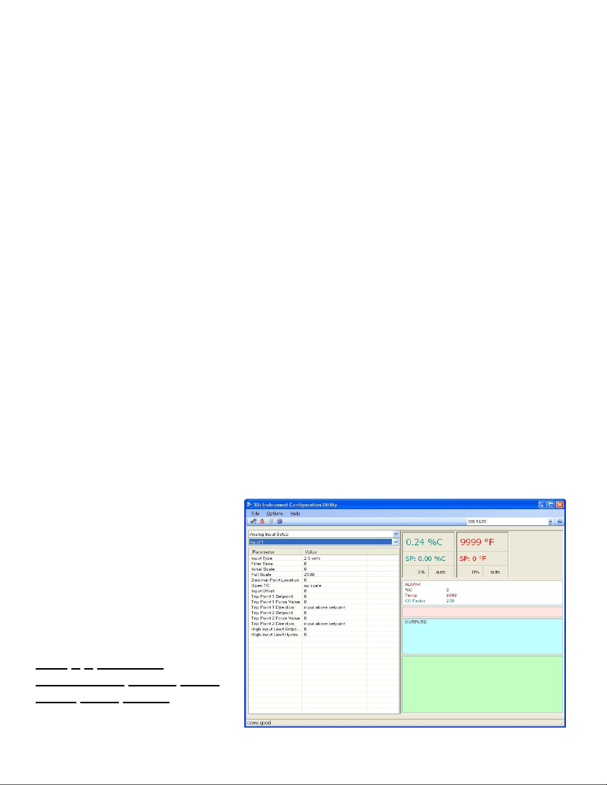
Parameter Definitions
Input Type
The thermocouple type for most applications can be modified depending on your specific needs. Please note that in some
applications, some of the inputs DO NOT allow the user to modify the Input type.
make sure to set the appropriate jumpers, if necessary
Furnace Setup
.
The jumper will need to be manually changed on the input board
section). It can be modified prior to shipment to your facility
before changing the input type to a 10:1 setting (non-thermocouple types)
input you want to change by selecting it in the pull-down menu just below the main menu list. Clicking on the Value will
display an input box, and then you can use the pull-down menu to select the desired parameter. Once selected, click
and the displayed Input type under Value will be the current type.
The following is a list of the options:
B S 12.5 volts
C T 781.25mv
E 2.5 volts 195.3125 mV
J 1.25 volts
K 78.125 mV
N 19.53125 mV
NNM 4-20 mA
R 25 volts
Filter time
The filter time is a factory applied averaging tool used to help maintain steady control in high EMI environments. The
filter time should not be adjusted with consulting SSI. Clicking on this value will display an input box from which the user
can select a new value. The range is 0 to 32767.
Initial Scale
This is the initial scale value. Clicking on this value will display an input box from which the user can select a new value.
The range is –32768 to 32767.
Full scale
This is the full scale value. Clicking on this value will display an input box from which the user can select a new value.
The range is –32768 to 32767.
Decimal Point Location
This is the decimal point location value. Clicking on this value will display an input box from which the user can select a
new value. The range is 0 to 4.
Open TC
This is the open TC value. Clicking on this value will toggle between up scale, and down scale.
Input Offset
The input offset value is algebraically added to the input value to adjust the input curve on read-out.
offsets are unscaled
. The range is –5000 to 5000.
Section 1 – 9120 Configurator Menus
Note: Before changing the input type,
. To change the Input type, first select which
Note: The input
section
.
OK
4574 - SSi 9120 Manual Rev A Page 12 Super Systems Inc
Page 13
Trip Point 1 Setpoint
This is the trip point 1 setpoint value. The range is –32768 to 32768.
Trip Point 1 Force Value
This is the trip point 1 force value. The range is –32768 to 32768.
Trip Point 1 Direction
This is the trip point 1 direction. The options are: input above setpoint or input below setpoint.
Trip Point 2 Setpoint
This is the trip point 2 setpoint value. The range is –32768 to 32768.
Trip Point 2 Force Value
This is the trip point 2 force value. The range is –32768 to 32768.
Trip Point 2 Direction
This is the trip point 2 direction. The options are: input above setpoint or input below setpoint.
High Input Limit Setpoint
This is the setpoint for the high input limit. The range for this can be –32768 to 32768.
High Input Limit Hysteresis
This is the hysteresis for the high input limit. The range for this can be –32768 to 32768.
Step 6 – Complete Configurator
Analog Output Setup
Menu Option
Note: This menu item is also located later
in the manual under the
Configurator Menus
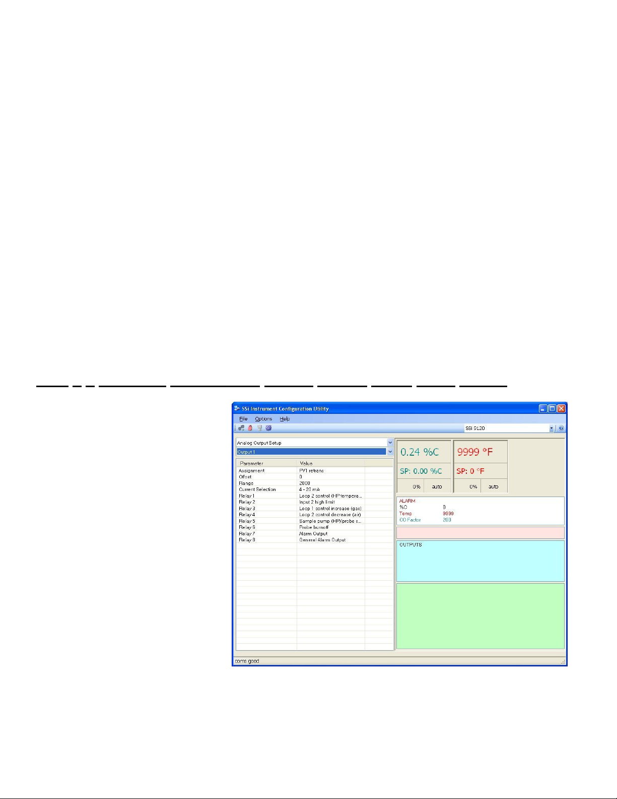
The 9120 controller has the option of two
analog outputs. The outputs are ranged
for a 4 – 20 milliamp signal or a 0 – 20
milliamp signal. Each output comes with
a factory default configuration dependent
on the application. Each output can be
modified prior to shipment to your facility
or in the field by a supervisor.
Analog Output Terminals
Analog output 1 – terminals 24 and 25
Analog output 2 – terminals 25 and 26
Assignment
The analog output assignment can be
modified depending on your system
requirements. To change the Assignment
first select which analog output you want
to change by selecting it in the pull-down
menu just below the main menu list.
Clicking on this value will display an input box, and then you can use the pull-down menu to select the desired parameter.
Once selected click OK and the displayed assignment under Value will be the current assignment type. The following is a
list of the options:
PV 1 retrans Input 1 retrans
Section 1 – 9120
section
.
4574 - SSi 9120 Manual Rev A Page 13 Super Systems Inc
Page 14

Loop 1 inc Input 2 retrans
Loop 1 dec Input 3 retrans
Loop 1 combo PV1 retrans w/ expo range
PV 2 retrans O2 offset log
Loop 2 inc SP1 retrans
Loop 2 dec SP2 retrans
Loop 2 combo DP retrans
Disassociation
Nit_Pot
Hydrogen
Combo example for carbon – 4 – 12 mA Air
12 – 20 mA Gas
Offset
This is the starting point, the Process Variable value at which you get 4 milliamps. Clicking on this value will display an
input box from which the user can select a new value. The range is –32768 to 32767.
Range
This is a Process Variable value between 4 and 20 milliamps. Clicking on this value will display an input box from which
the user can select a new value. The range is –32768 to 32767.
Note: The range, although not displayed with a
decimal point, contains a decimal point that is dependent on the process variable selected. For example, If the offset is
20 mV for 4 mA, and you want 100 mV to be 20 mA, then your range should be 80. If the process variable is
temperature, then the range will be 80, since temperature PVs do not have a decimal. If the PV is % Carbon, then the
range will need to include the two decimal points for % Carbon. So, a range of 80 will be entered as 8000
for more examples.
Current Selection
Provides the option of 4-20 mA or 0-20 mA control. Clicking on this value will display an input box with a drop-down
list from which the user can select either of the two values listed above.
Offset and Range when assigned to a control loop
Inc -- 0 = 4mA, 100 = 20mA
Dec -- 0 = 4mA, -100 = 20mA
Example: if 4 – 20 mA = 800 mV - 1200 mV and PV is Temperature
Offset = 800 (starting point)
Range = 400
Example: if 4 – 20 mA = 800 mV - 1200 mV and PV is O2
Offset = 800 (starting point)
Range = 4000 (400.0)
Example: if 4 – 20 mA = 800 mV - 1200 mV and PV is % Carbon
Offset = 800 (starting point)
Range = 40000 (400.00)
O2 Exponent Range
This menu option will allow the user to set the Oxygen exponent range. The range is 0 to 10.
The 9120 controller has the option of using eight relay outputs. All of the relays have a positive common terminal and
independent negative terminals. All of the relays are configured in a normally closed position except relay number eight,
which has both a normally closed (NC) and a normally open (NO) terminal.
. See below
4574 - SSi 9120 Manual Rev A Page 14 Super Systems Inc
Page 15

Note: Relay 1 through Relay 8 are display-only and cannot be modified from this screen
Relay Output Terminals
Relay Output 1 – terminals 7 and 8
Relay Output 2 – terminals 7 and 9
Relay Output 3 – terminals 7 and 10
Relay Output 4 – terminals 7 and 11
Relay Output 5 – terminals 7 and 12
Relay Output 6 – terminals 7 and 13
Relay Output 7 – terminals 7 and 14
Relay Output 8 – terminals 7 and 15 NC
Relay Output 8 – terminals 7 and 16 NO
.
Step 7 – Complete Configurator
Alarm Setup
Note: This menu item is also located later in the manual under the
drop-down lists from which the user can select a new value.
The values in the first (top) list box are:
PV 1 Value
PV 2 Value
PV 3 Value
Input 1 Value
Input 2 Value
Input 3 Value
PO1 Value
PO2 Value
PO3 Value
The values in the second (bottom) list box are:
Menu Option
Section 1 – 9120 Configurator Menus
The 9120 controller can be
configured to use three different
alarms. Each of the alarms consists
of an alarm setpoint, alarm type,
alarm hysteresis, smart alarm, ON
delay time, and a 0 SP blocks alarm
value. The alarms come from the
factory with a default configuration
dependent on the application but
also can be modified prior to
shipment to your facility or in the
field by a supervisor.
Setpoint
This value is the setpoint for the
alarm. Clicking on this value will
display an input box from which the
user can select a new value. The
range is from –9999 to 9999.
Alarm Type
This value is the type of alarms
used. Clicking on this value will
display an input box with two (2)
section
.
4574 - SSi 9120 Manual Rev A Page 15 Super Systems Inc
Page 16

Process High
Process Low
Band, Normally Open
Band, Normally Closed
Deviation, Normally Open
Deviation, Normally Closed
Deviation alarm is single sided. i.e. a +10 deviation will alarm when the PV is greater than SP + 10 but not neg. A -10
deviation will alarm when the PV is less than SP -10 but not on the positive side.
When set to deviation, the alarm message shows in Configurator below or above. The actual relay setup with that alarm
will only energize depending on the setpoint. For the standard alarms (1, 2, and 3), the user can select if the alarm
condition is for above or below. This will dictate when the relay will energize.
Example: alarm 1 set to plus 10F will alarm 11 degrees above setpoint and pull in the relay. It will show alarm 10 degrees
below but not pull in the relay.
A Band alarm will activate and energize the relay on both sides (+) and (-).
Note: some alarm types may be fixed at the current value
.
Hysteresis
The hysteresis is in degrees, i.e. 10 hysteresis = 10 degrees.
Alarm hysteresis should not have a decimal place. It is in units. If it is a control loop doing on/off control then the decimal
place on the reset (hysteresis) should be ignored. The Hysteresis is a set number that works with the alarm to help
control a motor or pump longer to reach a set amount to come back into band before it will shut off motor or pump.
Example: Using quench oil as an example, assume the SP is 200F. The alarm is set as a deviation of +10F. At 210 the
alarm is active and the pump will run to cool the oil. With a hysteresis of 8 degrees the alarm and pump will turn off at
202F. It will turn back on when it is 10 degrees above setpoint. If the setpoint is still 200 then at 210 it is on again.
Clicking on this value will display an input box from which the user can select a new value. The range is from 0 to 9999.
Smart Alarm
This value is a display of the Smart Alarm status. A smart alarm is an alarm that works with a Process Variable and when
enabled it will not be active until the process variable is within band of the setpoint.
Example: If the SP is 1700 and the band is 10 degrees
the alarm will not be active until the PV reaches 1690.
The value can be either disabled or enabled.
ON Delay Time
This value is the ON Delay Time for the Smart Alarm, in
seconds. If the timer is utilized the alarm will not be
active until in band and the timer has timed out (this is in
seconds).
Example: If you select 30, the output will not energize
until 30 seconds after the alarm is active.
Clicking on this value will display an input box from which
the user can select a new value. The range is from 0 to
9999 seconds.
0 SP Blocks Alarm
This value will allow a 0 setpoint to block an alarm. The
4574 - SSi 9120 Manual Rev A Page 16 Super Systems Inc
Page 17

options are either no or yes.
Step 8 – Complete Configurator
Note: This menu item is also located later in the manual under the
Communications Setup
666-4330 for more information regarding port setup. It is
without technical support from Super Systems Inc. Clicking on any of the values will display an input box that will allow
the user to modify the current settings.
is the communications definitions for the controller. Please contact Super Systems Inc. at 800-
Step 9 – Complete Configurator
Communications Setup
Section 1 – 9120 Configurator Menus
strongly recommended
PID Loop Setup
that none of the settings be modified
Menu Option
Menu option
section
.
Note: This menu item is also located later
in the manual under the
Configurator Menus
PID is the tuning parameters entered for
each Process Variable loop. The loop
value can be either Loop 1, or Loop 2.
Prop Band (0 for On/Off)
This is the proportional band field. This represents the P in PID. P = Proportional.
This is a field in which you want the process variable to stay around the setpoint.
Clicking on the value will allow the user to change the value. The range for the
proportional band value is 0 – 999.0.
Reset
This is the reset field. This represents the I in PID. I = Integral. This is the actual temperature being monitored over a
period of time and then averaged to keep within the Proportional band. The reset is in repeats per minute. This helps to
eliminate offset. Clicking on the value will allow the user to change the value. The reset range 0 – 100.00
Rate
This is the rate field. This represents the D in PID. D = Derivative. This is the sudden change or rate in the temperature.
This rate is in minutes. This affects the controller output which is proportional to the rate of change of the measurement
and will control the amount of output by time restraints. Thus derivative takes action to inhibit more rapid changes of the
measurement than proportional action. Derivative is often used to avoid overshoot. Clicking on the value will allow the
user to change the value. The range for the rate is 0 – 100.00. The rate is not typically used for heating/carbon
Section 1 – 9120
section
.
4574 - SSi 9120 Manual Rev A Page 17 Super Systems Inc
Page 18

Mode
This is the mode of the loop. Clicking on the value will allow the user to change the value.
The following is an explanation of the dual/single and direct/reverse properties:
Dual – This has two output relays which can increase and decrease to achieve your SP.
Single – This has one relay which works in only one direction to achieve your SP.
Direct - If the PV - SP is a positive number and the output would bring the PV down toward setpoint that is direct.
Reverse – If the PV - SP is a negative number and the output would bring the PV up toward setpoint then that is reverse
Example: If a 12 mA output drives a 0 degree F temp. (PV) up to a 1200 degree F temp. (SP) this would be REVERSE
and since this would take a SINGLE output from the controller the Mode for the Temperature Loop is Single Reverse.
The mode values can be:
Dual Reverse; gas/air or heat/cool
Single Reverse; heat
Dual Direct; Dewpoint gas/air
Single Direct; cool
Integral Preset
This field provides an offset for the starting point for PID control, also referred to as “Load Line” or “Manual Reset”.
Clicking on the value will allow the user to change the value. The range for the integral preset is –100 to 100.
Cycle Time
Clicking on the value will allow the user to change the value. This field is typically set to the valve travel time multiplied
by 1.5. The cycle time range can be 0 – 300.
Setpoint Change Limit
This is a smart time feature that allows the Process Loop to use PB only without Reset until the Process Variable drops
below the percent output set under this category.
It is used to eliminate overshoot.
The Output percentage selected under this category
furnace at heat.
Clicking on the value will allow the user to change the value.
must
be above the normal operating output percentage of the
Example – if the furnace runs at 40% output at heat for the maximum load, the setpoint change limit should be set to
.
60%
The value can be:
OFF
80 %
70 %
60 %
50 %
40 %
30 %
20 %
Low Limit
This is the low limit field. Clicking on the value will allow the user to change the value. The range is –100 to 100.
High Limit
This is the high limit field. Clicking on the value will allow the user to change the value. The range is –100 to 100.
0 Setpoint Stops Control
4574 - SSi 9120 Manual Rev A Page 18 Super Systems Inc
Page 19

If the Setpoint is zero, then all outputs are turned off. Clicking on the value will allow the user to change the value. The
option is either Yes or No.
4574 - SSi 9120 Manual Rev A Page 19 Super Systems Inc
Page 20

SSSSii 99112200 PPiinnoouutt DDiiaaggrraamm
SUPER SYSTEMS INC.
www.supersystems.com
(800) 666-4330
1 - 24VDC (COM)
2 - 24VDC (+)
3 - RS485 RT (-)
4 - RS485 RT (+)
5 - SLAVE 1 RS485 (-)
6 - SLAVE 1 RS485 (+)
7 - RELAY COMMON
8 - RELAY OUT 1
9 - RELAY OUT 2
10 - RELAY OUT 3
11 - RELAY OUT 4
12 - RELAY OUT 5
13 - RELAY OUT 6
14 - RELAY OUT 7
15 - RELAY OUT 8 NC
16 - RELAY OUT 8 NO
17 - DIGITAL IN 1
18 - DIGITAL IN 2
19 - DIGITAL IN 3
20 - DIGITAL IN 4
21 - DIGITAL IN COM
22 - SLAVE 2 RS485 (+)
23 - SLAVE 2 RS485 (-)
24 - 4-20mA OUT 1 (-)
25 - 4-20mA OUT COM (+)
26 - 4-20mA OUT 2 (-)
27 - ANALOG IN 3 (-)
28 - ANALOG IN 3 (+)
29 - ANALOG IN 2 (-)
30 - ANALOG IN 2 (+)
31 - ANALOG IN 1 (-)
32 - ANALOG IN 1 (+)
4574 - SSi 9120 Manual Rev A Page 20 Super Systems Inc
Page 21

SSSSii 99112200 WWiirriinngg DDiiaaggrraamm
21 3 54
876 1 09 1 31 1 1 2 1 61 51 4
P OR T BP OR T A
M OD E L
S/ N
2 72 42 2 2 3 2 5 2 6 2 8 2 9 3 13 0
3 22 11 7 1 8 2 01 9
4574 - SSi 9120 Manual Rev A Page 21 Super Systems Inc
Page 22

SSeeccttiioonn 11 –– 99112200 CCoonnffiigguurraattoorr MMeennuuss
Burnoff
When a probe is in a furnace, soot will
collect in the end of the probe, which will
have a negative effect on the performance
of the probe. Burnoffs are used to clean out
the built-up carbon by burning it off of the
probe. To manually begin a burnoff, click
on the “Value” area next to “Burnoff”. To
Cancel a burnoff, click on the “Value” area
next to “Cancel”.
“Cancel” are the only two interactive fields
on this screen; the rest are read-only
Note: “Burnoff” and
.
Burnoff
Clicking on the “Value” area next to this field will
user will have to confirm the initiation. Once a probe burnoff, has started, the rest of
the fields on the screen will be updated with the current values.
manuall
y initiate a probe burnoff. The
4574 - SSi 9120 Manual Rev A Page 22 Super Systems Inc
Page 23

Cancel
Clicking on the “Value” area next to this field will
user will have to confirm the cancellation.
Next Burnoff In (shown in minutes)
This value is a displayed calculation based on the burnoff time set in the
menu option. It displays the number of minutes until the next burnoff will be initiated.
Test Status
This value displays the current testing status. The list of possible values are: Burnoff, Burnoff Recovery, or Idle.
Timer (sec)
This value shows the remaining time, in seconds, for the Burnoff / Recoveries.
MV
This value is a display of the current millivolt input value during a burnoff.
TC
This value is a display of the current probe thermocouple input value during a burnoff.
Start mV
This value is a display of the millivolt input value at the beginning of the Burnoff.
Start TC
This value is a display of the probe thermocouple value at the beginning of the burnoff.
Last Burnoff
This value shows the date and time of the last burnoff.
Last Min mV
manually
cancel a probe burnoff. The
Burnoff Setup
This value is a display of the minimum
millivolts measured during the last burnoff.
Last Max TC
This value is a display of the maximum
measured probe thermocouple input value
during the last burnoff.
Slave Instruments
This page is a display of the current process
variables of each of the slave instruments
communicating with the 9120 controller.
Note – None of these values can be
modified on this screen
4574 - SSi 9120 Manual Rev A Page 23 Super Systems Inc
.
Page 24

For set-up of the auxiliary instruments go to the menu item
Aux Analog Inputs
This menu option shows the process
variables for the analog inputs of the 9120
controller. It also shows the input types and
any information from attached slave analog
input modules.
can be modified on this screen
Note – None of these values
.
Slave Instrument Setup
.
Burnoff Setup
This menu option allows the user to modify the settings that are associated with the probe burnoff (menu option
Burnoff
).
4574 - SSi 9120 Manual Rev A Page 24 Super Systems Inc
Page 25

Burnoff Time (sec)
The amount of time from the beginning of the burnoff to the end of the
burnoff measured in seconds. Clicking on the value will allow the user to
change the value.
Burnoff Recovery Wait Time (sec)
The amount of time allotted to allow the probe measurements to return to a
stable, accurate range after the burnoff is complete. This is measured in seconds. The control output is held until this
time is elapsed. Clicking on the value will allow the user to change the value.
Burnoff Interval (min)
The amount of time between the beginning of one burnoff and the beginning of the next scheduled burnoff measured in
minutes. Clicking on the value will allow the user to change the value.
Burnoff Minimum Millivolts
The minimum measured millivolt tolerance of the probe required to start a burnoff. If the millivolts value is exceeded
burnoff will stop
the user to change the value.
Burnoff Maximum Temperature
The maximum measured temperature allowed during a burnoff. If the temperature value is exceeded
. This is done to help maintain the life and the accuracy of your probe. Clicking on the value will allow the user to
stop
change the value.
. This is done to help maintain the life and the accuracy of your probe. Clicking on the value will allow
the burnoff will
the
PID Loop Setup
PID is the tuning parameters entered for
each Process Variable loop. The loop
value can be either Loop 1, or Loop 2.
Prop Band (0 for On/Off)
This is the proportional band field. This represents the P in PID. P = Proportional.
This is a field in which you want the process variable to stay around the setpoint.
4574 - SSi 9120 Manual Rev A Page 25 Super Systems Inc
Page 26

Clicking on the value will allow the user to change the value. The range for the proportional band value is 0 – 999.0.
Reset
This is the reset field. This represents the I in PID. I = Integral. This is the actual temperature being monitored over a
period of time and then averaged to keep within the Proportional band. The reset is in repeats per minute. This helps to
eliminate offset. Clicking on the value will allow the user to change the value. The reset range 0 – 100.00
Rate
This is the rate field. This represents the D in PID. D = Derivative. This is the sudden change or rate in the temperature.
This rate is in minutes. This affects the controller output which is proportional to the rate of change of the measurement
and will control the amount of output by time restraints. Thus derivative takes action to inhibit more rapid changes of the
measurement than proportional action. Derivative is often used to avoid overshoot. Clicking on the value will allow the
user to change the value. The range for the rate is 0 – 100.00. The rate is not typically used for heating/carbon
Mode
This is the mode of the loop. Clicking on the value will allow the user to change the value.
The following is an explanation of the dual/single and direct/reverse properties:
Dual – This has two output relays which can increase and decrease to achieve your SP.
Single – This has one relay which works in only one direction to achieve your SP.
Direct - If the PV - SP is a positive number and the output would bring the PV down toward setpoint that is direct.
Reverse – If the PV - SP is a negative number and the output would bring the PV up toward setpoint then that is reverse
Example: If a 12 mA output drives a 0 degree F temp. (PV) up to a 1200 degree F temp. (SP) this would be REVERSE
and since this would take a SINGLE output from the controller the Mode for the Temperature Loop is Single Reverse.
The mode values can be:
Dual Reverse; gas/air or heat/cool
Single Reverse; heat
Dual Direct; Dewpoint gas/air
Single Direct; cool
Integral Preset
This field provides an offset for the starting point for PID control, also referred to as “Load Line” or “Manual Reset”.
Clicking on the value will allow the user to change the value. The range for the integral preset is –100 to 100.
Cycle Time
Clicking on the value will allow the user to change the value. This field is typically set to the valve travel time multiplied
by 1.5. The cycle time range can be 0 – 300.
Setpoint Change Limit
This is a smart time feature that allows the Process Loop to use PB only without Reset until the Process Variable drops
below the percent output set under this category.
It is used to eliminate overshoot.
The Output percentage selected under this category
furnace at heat.
Clicking on the value will allow the user to change the value.
must
be above the normal operating output percentage of the
Example – if the furnace runs at 40% output at heat for the maximum load, the setpoint change limit should be set to
.
60%
The value can be:
OFF
80 %
70 %
60 %
4574 - SSi 9120 Manual Rev A Page 26 Super Systems Inc
Page 27

50 %
40 %
30 %
20 %
Low Limit
This is the low limit field. Clicking on the value will allow the user to change the value. The range is –100 to 100.
High Limit
This is the high limit field. Clicking on the value will allow the user to change the value. The range is –100 to 100.
0 Setpoint Stops Control
If the Setpoint is zero, then all outputs are turned off. Clicking on the value will allow the user to change the value. The
option is either Yes or No.
Furnace Setup
The Furnace Setup menu option is an
administrative access only option. Do not
make any adjustments on this screen
without first contacting Super Systems Inc.
Date and Time
This option will display the current date and
time on the 9120 controller. From this
menu option, the user can change the
date/time
Furnace Name
This value will define the name of the
furnace. Clicking on the “Value” column will
bring up an input box where the user can
enter the furnace’s name.
PV1 Name
This value will define the name of the first
process variable. Clicking on the “Value”
column will bring up an input box where the
user can enter the PV’s name.
PV2 Name
This value will define the name of the second process variable. Clicking on the “Value” column will bring up an input box
where the user can enter the PV’s name.
PVT Type
The PVT type is the mode the device runs in (Carbon, Dewpoint, etc.). The mode selected determines the calculations
and scaling for the Process Variable. Any time this selection is changed it is necessary to reset the factory defaults to
ensure all parameters have been changed to the new Process Variable (
Defaults button or FD Preserve button). Clicking on this value will display an input box with a drop-down list from
which the user can select a new PVT Type.
The values for the PVT type are:
% Carbon
Dew Point
Oxygen
Options
menu →
on the 9120 controller
Settings
menu option → Set
.
4574 - SSi 9120 Manual Rev A Page 27 Super Systems Inc
Page 28

Millivolt
Redundant Probe
Simple Nitrider
Dual Loop
Temperature Mode
This value determines the specific temperature scale to be used. Clicking on the value will allow the operator to change
the value. It can be either Degrees °°°°F or degrees °°°°C.
Level 1 Code
Typically, operations used by a supervisor require a level 1 code for access. When a supervisor is logged in, the lock on
the toolbar will be gold, . To change the level 1 passcode, click on the “Level 1 Code” value (range is –32768 to
32767) and an input box will be displayed where the user can select a new value.
Level 2 Code
Typically, operations used by an administrator require a level 2 code for access. When an administrator is logged in, the
lock on the toolbar will be green, . To change the level 2 passcode, click on the “Level 2 Code” value (range is –
32768 to 32767) and an input box will be displayed where the user can select a new value.
Web Level 1 Code
This value is the supervisor-level passcode for any web-based operations with the 9120 controller. Clicking on the value
will allow the operator to change the value. The range for the passcode is 0 to 9999.
Web Level 2 Code
This value is the administrator-level passcode for any web-based operations with the 9120 controller. Clicking on the
value will allow the operator to change the value. The range for the passcode is 0 to 9999.
Web Change Enable
This will either enable or disable the web change feature, which will allow changes to be made over the web page for the
9120 controller. Clicking on the value will allow the operator to change the value. Select either a 0 (Web Change
Disable) or a 1 (Web Change Enable).
O2 Mode
This value will allow the operator to select the oxygen mode.
Clicking on the value will allow the operator to change the value.
The options are:
% with control
Monitor
Offset with control.
Sample Pump Mode
Remote Setpoint
Remote Setpoint Hysteresis
Sample Pump Mode
This menu option will allow the user to turn the sample pump On or Off. For the HP PVT types (% Carbon, Dewpoint,
Oxygen, Millivolt, and Redundant Probe), there is the option to set a minimum temperature in order for the pump to
run. See the “Minimum Temp/Pump Run” description below.
Remote Setpoint
This option will allow the user to select where the remote setpoint will come from. The options are:
None
Slave 1 PV
4574 - SSi 9120 Manual Rev A Page 28 Super Systems Inc
Page 29

Slave 2 PV
Slave 1 SP
Slave 2 SP
Input 3 Value
Remote Setpoint Hysteresis
This option will allow the user to enter the remote setpoint hysteresis. The range is 0 to 9999.
Minimum temp/pump run
This option will set the minimum temperature for the pump to run, if that feature is used. A 0 value will disable the
minimum temperature feature.
for the pump minimum temperature feature to work
Input 1
This value will display the Input 1 type. This value cannot be changed from this screen.
Input 2
This value will display the Input 2 type. This value cannot be changed from this screen.
Input 3
This value will display the Input 3 type. This value cannot be changed from this screen.
Note: The furnace that is being sampled must have its temperature connected to input 3
.
Loop 1 PV
This value will display the Loop 1 PV type. This value cannot be changed from this screen.
Loop 2 PV
This value will display the Loop 2 PV type. This value cannot be changed from this screen.
Communications Setup
Communications Setup
666-4330 for more information regarding port setup. It is
is the communications definitions for the controller. Please contact Super Systems Inc. at 800-
strongly recommended
that none of the settings be modified
4574 - SSi 9120 Manual Rev A Page 29 Super Systems Inc
Page 30

without technical support from Super Systems Inc. Clicking on any of the values will display an input box that will allow
the user to modify the current settings.
Slave Instrument Setup
This menu option will allow the user to set up the
slave instruments for the 9120.
** All devices on the same slave port must utilize
the same protocol
** An address of zero (0) will disable the
instrument**
Some controllers (AC20, for example) can provide
dual functions (atmosphere and events) and must
have the same address assigned for both.
Clicking on the “Value” field for any instrument
will allow the user to select the slave instrument.
Instrument
This value will allow the user to select the slave instrument type.
The following is the list of instruments available as slave instruments:
SSi AC20 Eurotherm 2500 (temp) SSi Quad AO2
Yokogawa 750 (atm) Unipro v3.5 SSi Quad AO3
Honeywell UDC3300 (atm) Unipro v3.0 SSi Quad AO4
Dualpro LP1 Modbus (atm) Carbpro v3.5 Slave (temp) Yokogawa UT350
Dualpro LP2 Modbus (atm) Carbpro v3.0 Slave (temp) Yokogawa 750 Lp 2
Dualpro LP1 MMI (atm) 10Pro Yokogawa UP350
Dualpro LP2 MMI (atm) Dualpro IN C Honeywell DCP551
Eurotherm 2404 (atm) 9200 LP1 (temp) Ascon 08
Eurotherm 2500 (atm) 9200 LP2 (temp) SSi AC E
Cabpro v3.5 (atm) 9200 LP3 (temp) Yokogawa 750E
Cabpro v3.0 (atm) 9100 LP2 Mod Mux
CarbPC Eurotherm 2704 LP1 Dualpro E Modbus
9200 LP1 (atm) Eurotherm 2704 LP2 Dualpro E MMI
IR Base Eurotherm 2704 LP3 Carbpro E v3.5
MGA VC Base 1 Carbpro E v3.0
SSi 7EK VC Base 2 Eurotherm 2500
Yokogawa 750 (temp) VC Base 3 SSi 8-8
Honeywell UDC3300 (temp) VC Base 4 SSi 9200 E
Dualpro LP1 Modbus (temp) AIPC Micrologix PLC
Dualpro LP2 Modbus (temp) SSi 7SL MCM Module
Dualpro LP1 MMI (temp) AEC Flow Board PLC5 DF1
Dualpro LP2 MMI (temp) UMC800 LP1 SLC DF1
Eurotherm 2404 (temp) SSi Quad AO1
Address
4574 - SSi 9120 Manual Rev A Page 30 Super Systems Inc
Page 31

This value allows the user to select the address that corresponds with the controller selected, with a range of 0 to 249.
Port
Currently, the option for this field is Slave 1.
Slave 1 – terminals 5(-), 6(+)
Slave 2 – terminals 22(+), 23(-).
Analog Input Setup
The 9120 controller has two analog inputs. Each of the inputs comes with a factory default configuration dependent on
the application (refer to PVT type under the
or in the field by a technician or qualified/trained person with the proper security code.
Analog Input Terminals
Analog Input 1 – terminals 31 and 32
Analog Input 2 – terminals 29 and 30
Parameter Definitions
Input Type
The thermocouple type for most applications
can be modified depending on your specific
needs. Please note that in some applications,
some of the inputs DO NOT allow the user to
modify the Input type.
Note: Before changing
the input type, make sure to set the
.
appropriate jumpers, if necessary
The
jumper will need to be manually changed on
the input board before changing the input
type to a 10:1 setting (non-thermocouple
. To change the Input type, first select
types)
which input you want to change by selecting it
in the pull-down menu just below the main
menu list. Clicking on the Value will display an
input box, and then you can use the pull-down
menu to select the desired parameter. Once
selected, click
type under Value will be the current type.
The following is a list of the options:
B S 12.5 volts
C T 781.25mv
E 2.5 volts 195.3125 mV
J 1.25 volts
K 78.125 mV
N 19.53125 mV
NNM 4-20 mA
R 25 volts
Filter time
The filter time is a factory applied averaging tool used to help maintain steady control in high EMI environments. The
filter time should not be adjusted with consulting SSI. Clicking on this value will display an input box from which the user
can select a new value. The range is 0 to 32767.
Initial Scale
OK
and the displayed Input
Furnace Setup
section). It can be modified prior to shipment to your facility
4574 - SSi 9120 Manual Rev A Page 31 Super Systems Inc
Page 32

This is the initial scale value. Clicking on this value will display an input box from which the user can select a new value.
The range is –32768 to 32767.
Full scale
This is the full scale value. Clicking on this value will display an input box from which the user can select a new value.
The range is –32768 to 32767.
Decimal Point Location
This is the decimal point location value. Clicking on this value will display an input box from which the user can select a
new value. The range is 0 to 4.
Open TC
This is the open TC value. Clicking on this value will toggle between up scale, and down scale.
Input Offset
The input offset value is algebraically added to the input value to adjust the input curve on read-out.
offsets are unscaled
Trip Point 1 Setpoint
This is the trip point 1 setpoint value. The range is –32768 to 32768.
Trip Point 1 Force Value
This is the trip point 1 force value. The range is –32768 to 32768.
Trip Point 1 Direction
This is the trip point 1 direction. The options are: input above setpoint or input below setpoint.
Trip Point 2 Setpoint
This is the trip point 2 setpoint value. The range is –32768 to 32768.
Trip Point 2 Force Value
This is the trip point 2 force value. The
range is –32768 to 32768.
Trip Point 2 Direction
This is the trip point 2 direction. The
options are: input above setpoint or
input below setpoint.
High Input Limit Setpoint
This is the setpoint for the high input
limit. The range for this can be –
32768 to 32768.
High Input Limit Hysteresis
This is the hysteresis for the high input
limit. The range for this can be –
32768 to 32768.
. The range is –5000 to 5000.
Note: The input
Analog Output Setup
The 9120 controller has the option of
4574 - SSi 9120 Manual Rev A Page 32 Super Systems Inc
Page 33

two analog outputs. The outputs are ranged for a 4 – 20 milliamp signal or a 0 – 20 milliamp signal. Each output comes
with a factory default configuration dependent on the application. Each output can be modified prior to shipment to your
facility or in the field by a supervisor.
Analog Output Terminals
Analog output 1 – terminals 24 and 25
Analog output 2 – terminals 25 and 26
Assignment
The analog output assignment can be modified depending on your system requirements. To change the Assignment first
select which analog output you want to change by selecting it in the pull-down menu just below the main menu list.
Clicking on this value will display an input box, and then you can use the pull-down menu to select the desired parameter.
Once selected click OK and the displayed assignment under Value will be the current assignment type. The following is a
list of the options:
PV 1 retrans Input 1 retrans
Loop 1 inc Input 2 retrans
Loop 1 dec Input 3 retrans
Loop 1 combo PV1 retrans w/ expo range
PV 2 retrans O2 offset log
Loop 2 inc SP1 retrans
Loop 2 dec SP2 retrans
Loop 2 combo DP retrans
Disassociation
Nit_Pot
Hydrogen
Combo example for carbon – 4 – 12 mA Air
12 – 20 mA Gas
Offset
This is the starting point, the Process Variable value at which you get 4 milliamps. Clicking on this value will display an
input box from which the user can select a new value. The range is –32768 to 32767.
Range
This is a Process Variable value between 4 and 20 milliamps. Clicking on this value will display an input box from which
the user can select a new value. The range is –32768 to 32767.
Note: The range, although not displayed with a
decimal point, contains a decimal point that is dependent on the process variable selected. For example, If the offset is
20 mV for 4 mA, and you want 100 mV to be 20 mA, then your range should be 80. If the process variable is
temperature, then the range will be 80, since temperature PVs do not have a decimal. If the PV is % Carbon, then the
range will need to include the two decimal points for % Carbon. So, a range of 80 will be entered as 8000
for more examples.
Current Selection
Provides the option of 4-20 mA or 0-20 mA control. Clicking on this value will display an input box with a drop-down
list from which the user can select either of the two values listed above.
Offset and Range when assigned to a control loop
Inc -- 0 = 4mA, 100 = 20mA
Dec -- 0 = 4mA, -100 = 20mA
Example: if 4 – 20 mA = 800 mV - 1200 mV and PV is Temperature
Offset = 800 (starting point)
. See below
4574 - SSi 9120 Manual Rev A Page 33 Super Systems Inc
Page 34

Range = 400
Example: if 4 – 20 mA = 800 mV - 1200 mV and PV is O2
Offset = 800 (starting point)
Range = 4000 (400.0)
Example: if 4 – 20 mA = 800 mV - 1200 mV and PV is % Carbon
Offset = 800 (starting point)
Range = 40000 (400.00)
O2 Exponent Range
This menu option will allow the user to set the Oxygen exponent range. The range is 0 to 10.
The 9120 controller has the option of using eight relay outputs. All of the relays have a positive common terminal and
independent negative terminals. All of the relays are configured in a normally closed position except relay number eight,
which has both a normally closed (NC) and a normally open (NO) terminal.
Note: Relay 1 through Relay 8 are display-only and cannot be modified from this screen
Relay Output Terminals
Relay Output 1 – terminals 7 and 8
Relay Output 2 – terminals 7 and 9
Relay Output 3 – terminals 7 and 10
Relay Output 4 – terminals 7 and 11
Relay Output 5 – terminals 7 and 12
Relay Output 6 – terminals 7 and 13
Relay Output 7 – terminals 7 and 14
Relay Output 8 – terminals 7 and 15 NC
Relay Output 8 – terminals 7 and 16 NO
.
Alarm Setup
The 9120 controller can be
configured to use three different
alarms. Each of the alarms consists
of an alarm setpoint, alarm type,
alarm hysteresis, smart alarm, ON
delay time, and a 0 SP blocks alarm
value. The alarms come from the
factory with a default configuration
dependent on the application but
also can be modified prior to
shipment to your facility or in the
field by a supervisor.
Setpoint
This value is the setpoint for the
alarm. Clicking on this value will
display an input box from which the
user can select a new value. The
range is from –9999 to 9999.
Alarm Type
This value is the type of alarms
4574 - SSi 9120 Manual Rev A Page 34 Super Systems Inc
Page 35

used. Clicking on this value will display an input box with two (2) drop-down lists from which the user can select a new
value.
The values in the first (top) list box are:
PV 1 Value
PV 2 Value
PV 3 Value
Input 1 Value
Input 2 Value
Input 3 Value
PO1 Value
PO2 Value
PO3 Value
The values in the second (bottom) list box are:
Process High
Process Low
Band, Normally Open
Band, Normally Closed
Deviation, Normally Open
Deviation, Normally Closed
Deviation alarm is single sided. i.e. a +10 deviation will alarm when the PV is greater than SP + 10 but not neg. A -10
deviation will alarm when the PV is less than SP -10 but not on the positive side.
When set to deviation, the alarm message shows in Configurator below or above. The actual relay setup with that alarm
will only energize depending on the setpoint. For the standard alarms (1, 2, and 3), the user can select if the alarm
condition is for above or below. This will dictate when the relay will energize.
Example: alarm 1 set to plus 10F will alarm 11 degrees above setpoint and pull in the relay. It will show alarm 10 degrees
below but not pull in the relay.
A Band alarm will activate and energize the relay on both sides (+) and (-).
Note: some alarm types may be fixed at the current value
.
Hysteresis
The hysteresis is in degrees, i.e. 10 hysteresis = 10 degrees.
Alarm hysteresis should not have a decimal place. It is in units. If it is a control loop doing on/off control then the decimal
place on the reset (hysteresis) should be ignored. The Hysteresis is a set number that works with the alarm to help
control a motor or pump longer to reach a set amount to come back into band before it will shut off motor or pump.
Example: Using quench oil as an example, assume the SP is 200F. The alarm is set as a deviation of +10F. At 210 the
alarm is active and the pump will run to cool the oil. With a hysteresis of 8 degrees the alarm and pump will turn off at
202F. It will turn back on when it is 10 degrees above setpoint. If the setpoint is still 200 then at 210 it is on again.
Clicking on this value will display an input box from which the user can select a new value. The range is from 0 to 9999.
Smart Alarm
This value is a display of the Smart Alarm status. A smart alarm is an alarm that works with a Process Variable and when
enabled it will not be active until the process variable is within band of the setpoint.
Example: If the SP is 1700 and the band is 10 degrees the alarm will not be active until the PV reaches 1690. The value
can be either disabled or enabled.
ON Delay Time
4574 - SSi 9120 Manual Rev A Page 35 Super Systems Inc
Page 36

This value is the ON Delay Time for the Smart Alarm, in seconds. If the timer is utilized the alarm will not be active until
in band and the timer has timed out (this is in seconds).
Example: If you select 30, the output will not energize until 30 seconds after the alarm is active.
Clicking on this value will display an input box from which the user can select a new value. The range is from 0 to 9999
seconds.
0 SP Blocks Alarm
This value will allow a 0 setpoint to block an alarm. The options are either no or yes.
Calibration
Overview
The series 9120 controller can be calibrated using the operator interface Configurator software, usually supplied with the
system. Before performing this procedure on a newly installed controller, the unit needs to be powered on for at least
thirty (30) minutes for a warm up period to allow the inputs/outputs to stabilize with the environment.
The series 9120 has two analog inputs. Each range has a zero and span calibration value. A cold junction trim value must
be calibrated for thermocouple inputs. There are two analog outputs each with a zero and span value. When using the
User Calibration procedure this will allow for the user to only calibrate the input ranges being used in the controller for
which ever specific PVT is selected under furnace setup. The Full Calibration will calibrate all of the input ranges
regardless of what is selected for PVT.
Equipment needed
A certified calibrator(s) with the ability to input and read millivolts, milliamps and thermocouples is required. The
appropriate connection leads are also required. A 24VDC 75-watt power supply is required. The operator interface method
requires a PC with the Configurator software loaded. An Ethernet crossover cable is required.
4574 - SSi 9120 Manual Rev A Page 36 Super Systems Inc
Page 37

Calibration Procedure
The calibration procedure for an input or output will be the same regardless of which operation is being performed.
Zero Input: Source a zero mV value to the terminals. Press the Calibrate button.
Span Input: Source a specific mV value to the terminals and enter the value in the box. Press the Calibrate button.
Zero Output: Press the Prep for Zero button, which will set the output to 0%. Measure the current at the terminals and
output the measured value. Enter the value in the box. Press the Calibrate button.
Span Output: Press the Prep for Span button, which will set the output to 100%. Measure the current at the terminals
and output the measured value. Enter the value in the box. Press the Calibrate button.
User Calibration
Cold Junction Offset
Note: The cold junction offset should be performed after the inputs/outputs have been calibrated
If adjusting the input by a preset amount for all temperature points, calibrate the cold junction by entering a new value positive or negative – that would be the difference of the value indicated. Wait 120 seconds and verify with a source
calibration device with the correct T/C type. In the “Calibrate Cold Junction” section, enter the temperature of the
terminals and click on the Calibrate button. This will calibrate the cold junction value.
Zero/Span Input 1 / Range 0
Note: The inputs should be zeroed and spanned before
adjusting the cold junction offset
Procedure
value for the input. Press the Back button to return to
the previous screen or press the Next button to view the
next screen. Press the Done button to close the
calibration screen down.
Zero/Span Input 2 / Range 3
(listed above) to calibrate the zero and span
. Perform the
Calibration
Note: The inputs should be zeroed and spanned before
adjusting the cold junction offset
Procedure
value for the input. Press the Back button to return to
the previous screen or press the Next button to view the next screen. Press the Done button to close the calibration
screen down.
Zero/Span Input 3 / Range 3
(listed above) to calibrate the zero and span
. Perform the
Note: The inputs should be zeroed and spanned before adjusting the cold junction offset
Procedure
previous screen or press the Next button to view the next screen. Press the Done button to close the calibration screen
down.
Zero/Span Output 1
(listed above) to calibrate the zero and span value for the input. Press the Back button to return to the
Note: The inputs should be zeroed and spanned before adjusting the cold junction offset
Procedure
previous screen or press the Next button to view the next screen. Press the Done button to close the calibration screen
down.
Zero/Span Output 2
(listed above) to calibrate the zero and span value for the input. Press the Back button to return to the
Note: The inputs should be zeroed and spanned before adjusting the cold junction offset
Procedure
previous screen or press the Next button to view the next screen. Press the Done button to close the calibration screen
down.
(listed above) to calibrate the zero and span value for the input. Press the Back button to return to the
Calibration
. Perform the
. Perform the
. Perform the
.
Calibration
Calibration
Calibration
4574 - SSi 9120 Manual Rev A Page 37 Super Systems Inc
Page 38

Full Calibration
Cold Junction Offset
Note: The cold junction offset should be performed after the inputs/outputs have been calibrated
Note: These steps should only be performed if the User Calibration procedure did not calibrate the inputs and outputs
If adjusting the input by a preset amount for all temperature points, calibrate the cold junction by entering a new value positive or negative – that would be the difference of the value indicated. Wait 120 seconds and verify with a source
calibration device with the correct T/C type. In the “Calibrate Cold Junction” section, enter the temperature of the
terminals and click on the Calibrate button. This will calibrate the cold junction value. The Set Nominal button will set
nominal values for the cold junction value.
Zero/Span Input 0 / Range 0
Note: The inputs should be zeroed and spanned before
adjusting the cold junction offset
Procedure
value for the input. Press the Back button to return to the
previous screen or press the Next button to view the next
screen. The Set Nominal button will set nominal values
for the inputs. Press the Done button to close the
calibration screen down.
Zero/Span Input 0 / Range 1
(listed above) to calibrate the zero and span
. Perform the
Calibration
Note: The inputs should be zeroed and spanned before
adjusting the cold junction offset
Procedure
value for the input. Press the Back button to return to the previous screen or press the Next button to view the next
screen. The Set Nominal button will set nominal values for the inputs. Press the Done button to close the calibration
screen down.
Zero/Span Input 0 / Range 2
(listed above) to calibrate the zero and span
. Perform the
Note: The inputs should be zeroed and spanned before adjusting the cold junction offset
Procedure
previous screen or press the Next button to view the next screen. The Set Nominal button will set nominal values for
the inputs. Press the Done button to close the calibration screen down.
Zero/Span Input 0 / Range 3
(listed above) to calibrate the zero and span value for the input. Press the Back button to return to the
Note: The inputs should be zeroed and spanned before adjusting the cold junction offset
Procedure
previous screen or press the Next button to view the next screen. The Set Nominal button will set nominal values for
the inputs. Press the Done button to close the calibration screen down.
Zero/Span Input 1 / Range 0
(listed above) to calibrate the zero and span value for the input. Press the Back button to return to the
Note: The inputs should be zeroed and spanned before adjusting the cold junction offset
Procedure
previous screen or press the Next button to view the next screen. The Set Nominal button will set nominal values for
the inputs. Press the Done button to close the calibration screen down.
Zero/Span Input 1 / Range 1
(listed above) to calibrate the zero and span value for the input. Press the Back button to return to the
Note: The inputs should be zeroed and spanned before adjusting the cold junction offset
Procedure
(listed above) to calibrate the zero and span value for the input. Press the Back button to return to the
Calibration
. Perform the
. Perform the
. Perform the
. Perform the
.
.
Calibration
Calibration
Calibration
Calibration
4574 - SSi 9120 Manual Rev A Page 38 Super Systems Inc
Page 39

previous screen or press the Next button to view the next screen. The Set Nominal button will set nominal values for
the inputs. Press the Done button to close the calibration screen down.
Zero/Span Input 1 / Range 2
Note: The inputs should be zeroed and spanned before adjusting the cold junction offset
Procedure
previous screen or press the Next button to view the next screen. The Set Nominal button will set nominal values for
the inputs. Press the Done button to close the calibration screen down.
Zero/Span Input 1 / Range 3
(listed above) to calibrate the zero and span value for the input. Press the Back button to return to the
Note: The inputs should be zeroed and spanned before adjusting the cold junction offset
Procedure
previous screen or press the Next button to view the next screen. The Set Nominal button will set nominal values for
the inputs. Press the Done button to close the calibration screen down.
Zero/Span Input 2 / Range 0
(listed above) to calibrate the zero and span value for the input. Press the Back button to return to the
Note: The inputs should be zeroed and spanned before adjusting the cold junction offset
Procedure
previous screen or press the Next button to view the next screen. The Set Nominal button will set nominal values for
the inputs. Press the Done button to close the calibration screen down.
Zero/Span Input 2 / Range 1
(listed above) to calibrate the zero and span value for the input. Press the Back button to return to the
Note: The inputs should be zeroed and spanned before adjusting the cold junction offset
Procedure
previous screen or press the Next button to view the next screen. The Set Nominal button will set nominal values for
the inputs. Press the Done button to close the calibration screen down.
Zero/Span Input 2 / Range 2
(listed above) to calibrate the zero and span value for the input. Press the Back button to return to the
Note: The inputs should be zeroed and spanned before adjusting the cold junction offset
Procedure
previous screen or press the Next button to view the next screen. The Set Nominal button will set nominal values for
the inputs. Press the Done button to close the calibration screen down.
Zero/Span Input 2 / Range 3
(listed above) to calibrate the zero and span value for the input. Press the Back button to return to the
Note: The inputs should be zeroed and spanned before adjusting the cold junction offset
Procedure
previous screen or press the Next button to view the next screen. The Set Nominal button will set nominal values for
the inputs. Press the Done button to close the calibration screen down.
Zero/Span Input 1 Range Jumper
(listed above) to calibrate the zero and span value for the input. Press the Back button to return to the
Note: The inputs should be zeroed and spanned before adjusting the cold junction offset
Procedure
previous screen or press the Next button to view the next screen. The Set Nominal button will set nominal values for
the inputs. Press the Done button to close the calibration screen down.
Zero/Span Input 2 Range Jumper
(listed above) to calibrate the zero and span value for the input. Press the Back button to return to the
Note: The inputs should be zeroed and spanned before adjusting the cold junction offset
Procedure
previous screen or press the Next button to view the next screen. The Set Nominal button will set nominal values for
the inputs. Press the Done button to close the calibration screen down.
Zero/Span Input 3 Range Jumper
(listed above) to calibrate the zero and span value for the input. Press the Back button to return to the
. Perform the
. Perform the
. Perform the
. Perform the
. Perform the
. Perform the
. Perform the
. Perform the
Calibration
Calibration
Calibration
Calibration
Calibration
Calibration
Calibration
Calibration
4574 - SSi 9120 Manual Rev A Page 39 Super Systems Inc
Page 40

Note: The inputs should be zeroed and spanned before adjusting the cold junction offset
Procedure
previous screen or press the Next button to view the next screen. The Set Nominal button will set nominal values for
the inputs. Press the Done button to close the calibration screen down.
Zero/Span Output 1
(listed above) to calibrate the zero and span value for the input. Press the Back button to return to the
Note: The inputs should be zeroed and spanned before adjusting the cold junction offset
Procedure
previous screen or press the Next button to view the next screen. The Set Nominal button will set nominal values for
the inputs. Press the Done button to close the calibration screen down.
Zero/Span Output 2
(listed above) to calibrate the zero and span value for the input. Press the Back button to return to the
Note: The inputs should be zeroed and spanned before adjusting the cold junction offset
Procedure
previous screen or press the Next button to view the next screen. The Set Nominal button will set nominal values for
the inputs. Press the Done button to close the calibration screen down.
(listed above) to calibrate the zero and span value for the input. Press the Back button to return to the
. Perform the
. Perform the
. Perform the
Calibration
Calibration
Calibration
4574 - SSi 9120 Manual Rev A Page 40 Super Systems Inc
Page 41

AAppppeennddiixx 11 –– SSttaannddaarrdd CCoonnffiigguurraattiioonnss ffoorr PPVVTT TTyyppeess
PVT Type Standard Configuration
% Carbon Input 1 is sensor millivolts, and is set to 2.5 volts (fixed)
Input 2 is HP/sensor temperature and will only allow TC types
Input 3 is universal and is set to control loop 2
Control loop 1 PV is %C calculated from inputs 1 and 2
Control loop 2 PV is temperature from input 2
Dew Point Input 1 is sensor millivolts, and is set to 2.5 volts (fixed)
Input 2 is HP/sensor temperature and will only allow TC types
Input 3 is universal and is set to control loop 2
Control loop 1 PV is Dew Point calculated from inputs 1 and 2
Control loop 2 PV is temperature from input 2
% Oxygen Input 1 is sensor millivolts, and is set to 1.25 volts (fixed)
Input 2 is HP/sensor temperature and will only allow TC types
Input 3 is universal and is set to control loop 2
Control loop 1 PV is %O2 calculated from inputs 1 and 2
Control loop 2 PV is temperature from input 2
Millivolts Input 1 is sensor millivolts, and is set to 2.5 volts (fixed)
Input 2 is HP/sensor temperature and will only allow TC types
Input 3 is universal and is set to control loop 2
Control loop 1 PV is millivolts from input 1
Control loop 2 PV is temperature from input 2
Probe Redundancy Input 1 is probe #1 millivolts, and is set to 2.5 volts (fixed)
Input 2 is probe #2 millivolts, and is set to 2.5 volts (fixed)
Input 3 is universal and is set to control loop 1
Control loop 1 PV is universal from input 3
Simple Nitrider Input 1 is not used
Input 2 is not used
Input 3 is not used
No control loops
Analog output 1 is H2 0 – 100%
Analog output 2 is DA 0 – 100%
Dual Loop Input 1 is universal and assigned to control loop 1
Input 2 is universal and assigned to control loop 2
Input 3 is universal and is not used
Control loop 1 PV is millivolts from input 1
Control loop 2 PV is temperature from input 2
Note: All of these values can be viewed from the
Note: All of these values can be viewed from the
Note: All of these values can be viewed from the
Note: All of these values can be viewed from the
Note: All of these values can be viewed from the
Note: All of these values can be viewed from the
Note: All of these values can be viewed from the
Furnace Setup
Furnace Setup
Furnace Setup
Furnace Setup
Furnace Setup
Furnace Setup
Furnace Setup
menu option
menu option
menu option
menu option
menu option
menu option
menu option
4574 - SSi 9120 Manual Rev A Page 41 Super Systems Inc
Page 42

Outputs
Analog output 1 defaults as Loop 1 PV retrans except when PVT = Simple Nitrider (output 1 is H2 0 – 100%)
Analog output 2 defaults as Loop 1 control except when PVT = Simple Nitrider (output 2 is DA 0 – 100%)
Relay 1 is always loop 2 control (HP temperature)
Relay 2 is always input 2 high limit
Relay 3 is loop 1 control increase (gas) except when PVT = %Oxygen (Relay 3 is loop 1 control decrease)
Relay 4 is loop 2 control decrease (air) except when PVT = %Oxygen (Relay 4 is loop 2 control increase)
Relay 5 is always sample pump for HP except when PVT = Probe Redundancy (Relay 5 is probe select)
Relay 6 is always probe burnoff
Relay 7 is selectable alarm output (any combination)
Relay 8 is always general alarm output (any alarm)
Alarms
Alarm 1 is always process high on input 2
Alarm 2 is fully assignable
Alarm 3 is fully assignable
Digital Inputs (Event Inputs)
Digital Input 1 (event In 0) selects probe 1 when PVT = Probe Redundancy only
Digital Input 2 (event In 2) selects probe 2 when PVT = Probe Redundancy only
Digital Input 3 (event In 2) inhibits sample pump for HP only
Digital Input 4 (event In 3) starts probe burnoff when PVT = % Carbon, Dew Point, % Oxygen, or Millivolts
Note: Probe burnoff is available only for PVT types: % Carbon, Dew Point, % Oxygen, and Millivolts
.
impedance test.
.
Note: Dew Point is calculated only for PVT types: % Carbon, Dew Point, % Oxygen, and Millivolts
No
4574 - SSi 9120 Manual Rev A Page 42 Super Systems Inc
Page 43

AAppppeennddiixx 22 –– AAcccceessssiinngg tthhee SSSSii 99112200 WWeebb PPaaggee
Each SSi 9120 comes equipped with a small webpage that can be accessed over a company’s network, or through a local
computer hooked up to the 9120 with a crossover cable. To access the web page, enter the IP address of the SSi 9120
instrument into the address bar of any Internet browser.
Note: Viewing the web page requires the Java platform to be
installed on the local computer. Also, some security settings in Internet Explorer 7 may cause the website to not be
displayed, even if Java is installed
onto a local computer, and the required Internet Explorer 7 settings.
Once the IP
address of
the
instrument
is entered,
press the
Enter
button on the keyboard, or press the “Go” button next to the address bar. The user can navigate through the web page
by using the buttons along the top of the screen, or the buttons along the bottom of the screen. The first page shown is
the
Home
page. This page will display the two process variables and the two setpoints. This page is mainly a displayonly page. The next page is the
Setpoint 2) for either loop as well as set the loops to auto or manual(Auto/Man 1 or Auto/Man 2). If the loops are in
manual mode, the user will also be able to set the control percentage as well (Output PWR 1 and Output PWR 2). The
Set Value button will set the setpoints and manual control percentages.
. Contact your company’s IT department for more information on downloading Java
Operator
page. This page will allow the user send down a setpoint (Setpoint 1 or
Note: The user will need to be logged in as a
4574 - SSi 9120 Manual Rev A Page 43 Super Systems Inc
Page 44

supervisor or administrator to make any changes
Configurator’s
page is the
Also, the user will need to be logged in as an administrator (web level 2 code from Configurator
make any changes. From this screen, the user can change the following for each loop: Setpoint, manual control
percentage, Proportional Band (P), Reset (I), Rate (D), Cycle time, Integral preset, High limit, and low limit. The next
page is the
impedance test is in progress. The user will also be able to start a burnoff or impedance test from this page.
Furnace Setup
PID Tuning
Probe
page. This screen will allow the user to view the probe burnoff settings and progress, if a burnoff or
menu option (supervisor = web level 1 code; administrator = web level 2 code). The next
page. This page is similar in function to the
user will need to be logged in as an administrator (web level 2 code from Configurator
changes
make even more changes to the instrument.
code from Configurator
for each loop: Setpoint, manual control percentage, CO Factor, Proportional Band (P), Reset (I), Rate (D), Cycle time,
Integral preset, High limit, low limit, alarm setpoint, alarm hysteresis, Burnoff interval, burnoff time, burnoff recovery
time, burnoff minimum mV, and burnoff maximum TC. This page will also display information about the two loops, alarm
information, and input information. The next page is the
should help the user to navigate and use the web page. The last page is the
auxiliary analog inputs, if any.
. The next page is the
Furnace Setup
Supervisor
menu) to make any changes
page. This page is similar to the PID Tuning page, but it will allow the user to
. The supervisor and administrator passwords can be changed from
Operator
page, but it will entail more information.
Furnace Setup
menu) to
Note: The
Furnace Setup
menu) to make any
Note: The user will need to be logged in as an administrator (web level 2
. From this screen, the user can change the following
Help
page. This page displays some general help topics that
AUX A/I
page. This page will display any
4574 - SSi 9120 Manual Rev A Page 44 Super Systems Inc
Page 45

RReevviissiioonn HHiissttoorryy
Rev Description Date MCO #
- Initial Release 6/23/2008 N/A
A Updated “Analog Output Setup” section; Added minimum temp pump
8/18/2008 2065
run in “Furnace Setup” section
4574 - SSi 9120 Manual Rev A Page 45 Super Systems Inc
 Loading...