

Page 1
Series 3 PID Temperature
Controller
OPERATIONS MANUAL
P/N 31333
Super Systems Inc.
72 05 Edington Drive
Cincinnati, OH 45249
Ph : 513-772-0060, 800-666-4330
Fax: 513-772-9466
www.supersystems.com
Page 2

Operations Manual Series 3
Series 3 PID Temperature Controller
Operations Manual
Series 3 Controller
Contents
Installation and Basic Operation What Instrument Do I Have? ...................................................................................... 6
1.1 Unpacking Your Controller ...................................................................................................................................................6
1.2
Dimensions ...........................................................................................................................................................................6
1.3
Step 1: Installation ...............................................................................................................................................................7
1.3.1
Panel Mounting t he Controller ...............................................................................................................................................7
1.3.2
Panel Cut Out Sizes ................................................................................................................................................................7
1.3.3
Recommended minimum spacing of c ontrollers .....................................................................................................................7
1.3.4
To Remove the Controller from its Sleeve ...............................................................................................................................7
2. Step 2: Wiring ............................................................................................................................................ 8
2.1 Terminal Layout Series 3 Controller .....................................................................................................................................8
2.2
Wire Sizes .............................................................................................................................................................................9
2.3
Precautions ...........................................................................................................................................................................9
2.4
Sensor Input (Measuring Input) .............................................................................................................................................9
2.4.1
Thermocoup le Input ..............................................................................................................................................................9
2.4.2
RTD Input ..............................................................................................................................................................................9
2.4.3
Linear Input (mA or mV) .........................................................................................................................................................9
2.4.4
Two-Wire Transmitter Inputs ..................................................................................................................................................9
2.5
Input/Output 1 & Output 2 ....................................................................................................................................................10
2.5.1
Relay Output (Form A, normally open) ...................................................................................................................................10
2.5.2
Logic (SSR drive) Output ........................................................................................................................................................10
2.5.3
DC Out put .............................................................................................................................................................................10
2.5.4
Triac Output ..........................................................................................................................................................................10
2.5.5
Logic Co ntact Closure Inp ut (I/O 1 only) ..................................................................................................................................10
2.6
Remote Setpoint Input .........................................................................................................................................................10
2.7
Output 3 ...............................................................................................................................................................................10
2.8
Summary of DC Outputs .......................................................................................................................................................10
2.9
Output 4 (AA Relay) ..............................................................................................................................................................11
2.10
General Note About Relays and Inductive Loads ..................................................................................................................11
2.11
Digital Inputs A & B ...............................................................................................................................................................11
2.12
Transmitter Power Supply ....................................................................................................................................................11
2.13
Digital Communications ........................................................................................................................................................12
2.14
Controller Power Supply .......................................................................................................................................................13
2.15
Example Heat/Cool Wiring Diagram .....................................................................................................................................13
3. Safety and EMC Information ...................................................................................................................... 14
3.1 Installation Safety Requirements ..........................................................................................................................................14
4. Switch On .................................................................................................................................................. 16
4.1 New Controller .....................................................................................................................................................................16
4.1.1
Quick Start Code ...................................................................................................................................................................16
4.2
To Re-Enter Quick Code mode ..............................................................................................................................................17
4.3
Pre-Configured Controller or Subsequent Starts ...................................................................................................................17
4.4
Front Panel Layout ...............................................................................................................................................................18
4.4.1
To Set The Target Temperature. .............................................................................................................................................18
4.4.2
Alarms ...................................................................................................................................................................................18
4.4.3
Alarm Indication ....................................................................................................................................................................18
4.4.4
Auto, Manual and Off Mode ...................................................................................................................................................20
4.4.5
To Select Auto, Manual or Off Mode .......................................................................................................................................20
4.4.6
Level 1 Operator Parameters ..................................................................................................................................................21
5. Operator Level 2 ........................................................................................................................................ 21
5.1 To Enter Level 2 ....................................................................................................................................................................21
5.2
To Return to Level 1 .............................................................................................................................................................21
5.3
Level 2 Parameters ...............................................................................................................................................................21
6. Access to Further Parameters .................................................................................................................... 25
6.1.1 Level 3 ...................................................................................................................................................................................25
6.1.2
Configuration Level ...............................................................................................................................................................25
6.1.3
To Select Access Level 3 or Configuration Level .......................................................................................................................26
6.2
Parameter lists ......................................................................................................................................................................27
6.2.1
To Choose Parameter List Headers .........................................................................................................................................27
6.2.2
To Locate a Parameter ...........................................................................................................................................................27
6.2.3
How P arameters are Displayed ..............................................................................................................................................27
6.2.4
To Change a Parameter Value ................................................................................................................................................27
6.2.5
To Return to the HOME Display ..............................................................................................................................................27
6.2.6
Time Out ...............................................................................................................................................................................27
6.3
Navigation Diagram ..............................................................................................................................................................28
2
Page 3

Series 3 Operations Manual
6.4 Access Parameters ............................................................................................................................................................... 29
7. Controller Block Diagram ........................................................................................................................... 31
8.
Temperature (or Process) Input ................................................................................................................. 32
8.1 Process Input Parameters .................................................................................................................................................... 32
8.1.1
Input Types and Ranges ........................................................................................................................................................ 33
8.1.2
Operation of Sensor Break .................................................................................................................................................... 34
8.2
PV Offset ............................................................................................................................................................................. 35
8.2.1
Example: To Apply an Offset: ............................................................................................................................................... 35
8.3
PV Input Scaling .................................................................................................................................................................. 35
8.3.1
Example: To Scale a Linear Input ........................................................................................................................................... 35
9. Input/Output ............................................................................................................................................. 36
9.1 Input/Output Parameters ..................................................................................................................................................... 37
9.1.1
Input /Output 1 List (IO-1) ...................................................................................................................................................... 37
9.1.2
Remote Digital Setpoint Select and Remote Fail .................................................................................................................... 38
9.1.3
Sense ................................................................................................................................................................................... 38
9.1.4
Source .................................................................................................................................................................................. 38
9.1.5
Po wer Fail ............................................................................................................................................................................. 38
9.1.6
Example: To Configure IO-1 Relay to Operate on Alarms 1 and 2: ........................................................................................... 38
9.1.7 Output List 2 (OP-2) ............................................................................................................................................................. 39
9.1.8
Output List 3 (OP-3) .............................................................................................................................................................. 39
9.1.9
AA Relay (AA) (Output 4) ...................................................................................................................................................... 40
9.1.10
Digital Inp ut Parameters .................................................................................................................................................. 41
9.2
Current Transformer Input Parameters (Current Transformer is not available) .................................................................... 42
10. Setpoint Generator .................................................................................................................................... 43
10.1 Setpoint Parameters ............................................................................................................................................................ 43
10.2
Example: To Set Ramp Rate ............................................................................................................................................... 44
11. Control ...................................................................................................................................................... 45
11.1 Types of Control .................................................................................................................................................................. 45
11.1.1
On/Off Control ................................................................................................................................................................ 45
11.1.2
PID Control ...................................................................................................................................................................... 45
11.2
Control Parameters .............................................................................................................................................................. 46
11.2.1
Proportional Band ‘PB’ ..................................................................................................................................................... 48
11.2.2
Integral Term ‘TI’ .............................................................................................................................................................. 48
11.2.3
Derivative Term ‘TD’ ........................................................................................................................................................ 49
11.2.4
Relative Cool Gain ‘R2G’ ................................................................................................................................................... 49
11.2.5
High and Low Cutback ..................................................................................................................................................... 50
11.2.6
Manual Reset ................................................................................................................................................................... 50
11.2.7
Control Action ................................................................................................................................................................. 50
11.2.8
Loop Break ...................................................................................................................................................................... 50
11.2.9
Cooling Algorithm ........................................................................................................................................................... 50
11.3
Tuning ................................................................................................................................................................................. 50
11.3.1
Loop Response ................................................................................................................................................................ 51
11.3.2
Initial Settings ................................................................................................................................................................. 51
11.3.3
Automa tic Tuning ............................................................................................................................................................ 53
11.3.4
To Start Autotune ............................................................................................................................................................ 53
11.3.5
Autotune from Below SP – Heat/Cool ............................................................................................................................... 54
11.3.6
Autotune From Below SP – Heat Only .............................................................................................................................. 55
11.3.7
Autotune at Setpoint – Heat/Cool ......................................................................................................................................... 56
11.3.8
Manual Tuning ................................................................................................................................................................. 56
11.3.9
Manually Setting Relative Cool Gain ................................................................................................................................. 57
11.3.10
Manually Setting the Cutback Values ............................................................................................................................... 58
11.4
Auto-tune Configures R2G ................................................................................................................................................... 59
11.5
Example: To Configure Heating and Cooling ....................................................................................................................... 60
11.5.1
Effect of Control Action, Hysteresis and Deadband ........................................................................................................... 61
12. Alarms ....................................................................................................................................................... 62
12.1 Types of Alarm ..................................................................................................................................................................... 62
12.1.1
Alarm Rela y Output ......................................................................................................................................................... 64
12.1.2
Alarm Indication .............................................................................................................................................................. 64
12.1.3
To Acknowledge An Alarm ............................................................................................................................................... 64
12.2
Behaviour of Alarms After a Power Cycle ............................................................................................................................. 65
12.2.1
Examp le 1 ........................................................................................................................................................................ 65
12.2.2
Example 2 ........................................................................................................................................................................ 65
12.2.3
Examp le 3 ........................................................................................................................................................................ 65
12.3
Alarm Parameters ................................................................................................................................................................ 66
12.3.1
Example: To Co nfigure Alarm 1 ........................................................................................................................................ 67
12.4
Diagnostic Alarms ................................................................................................................................................................ 68
12.4.1
Out of Range Indication ................................................................................................................................................... 68
13. Digital Communications ............................................................................................................................. 69
13.1 Digital Communications Wiring ............................................................................................................................................ 69
13.1.1
EIA485 ( 2-wire) ................................................................................................................................................................ 69
3
Page 4

Operations Manual Series 3
13.2 Digital Communications Parameters .....................................................................................................................................70
13.3
Example: To Set Up Instrument Address ..............................................................................................................................71
13.4
DATA ENCODING .................................................................................................................................................................71
13.5
Parameter Modbus Addresses ...............................................................................................................................................71
14. Calibration ................................................................................................................................................. 81
14.1 To Check Input Calibration ....................................................................................................................................................81
14.1.1
Precautions ......................................................................................................................................................................81
14.1.2
To Check mV Input Calibratio n ..........................................................................................................................................81
14.1.3
To Check Thermocouple Input Calibration .........................................................................................................................81
14.1.4
To Check RTD Input Calibration ........................................................................................................................................81
14.2
Offsets ..................................................................................................................................................................................82
14.2.1
Two Point Offset ..............................................................................................................................................................82
14.2.2
To Apply a Two Point Offset .............................................................................................................................................83
14.2.3
To Remove the Two Point Offset ......................................................................................................................................83
14.3
Input Calibration ...................................................................................................................................................................84
14.3.1
To Calibrate mV Input .......................................................................................................................................................84
14.3.2
To Calibrate Thermocouple Input ......................................................................................................................................85
14.3.3
To Calibrate RTD Input ......................................................................................................................................................86
14.3.4
To Calibrate mA Outputs ..................................................................................................................................................87
14.3.5 To Calibrate Remote Setpoint Input ..................................................................................................................................88
14.3.6
To Return to Factory Calibration .......................................................................................................................................89
14.4
Calibration Parameters .........................................................................................................................................................90
15. Appendix A TECHNICAL SPECIFICATION .................................................................................................. 91
4
Page 5

Series 3 Operations Manual
Issue Status of this Manual
Issue 5 of this Handbook applies to software versions 2.09 and above for PID controller and 2.29 and above for Valve Position
controllers and includes:
• Remote Setpoint Input Option RCL
• Triac output
It also applies to firmware versions 2.11 and includes new parameters:
Inverted status word
Rate of change alarms
Setpoint retransmission limits
Input filter
Issue 6 includes parameter ‘AT.R2G’
Issue 7 corrects range limits. Change to definition of LOC.T. Correct description of enumerations for parameter IM.
Issue 8 includes the following changes:
A more detailed description of loop tuning.
Updates to Appendix A, Technical Specification.
5
Page 6
Operations Manual Series 3
Installation and Basic Operation What Instrument Do I Have?
Thank you for choosing this Series 3 Temperature Controller.
The Series 3 provides precise temperature control of
industrial processes and is available in one standard DIN size:
• 1/4 DIN
A universal input accepts various thermocouples, RTDs or
process inputs. Up to four outputs can be configured for
control, alarm or re-transmission purposes. 485
communication is also available.
The controller may have been ordered pre-configured or
setup with defualt configuration..
If the display shows SET 1 the controller was supplied
without parameters and will need to be configured when it
is first switched on.
This Manual takes you through all aspects of installation,
wiring, configuration and use of the controller.
1.1 Unpacking Your Controller
The controller is supplied with
• Sleeve (with the controller fitted in the sleeve)
• Two panel retaining clips and sealing gasket mounted
on the sleeve
• Component packet containing a snubber for relay
output and a 2.49Ω resistor for current inputs.
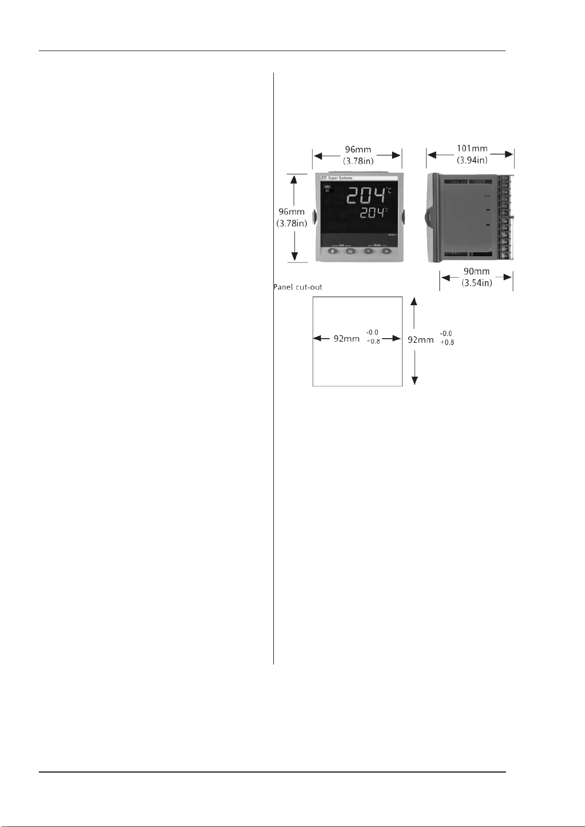
1.2 Dimensions
General views of the controller are shown below together
with overall dimensions.
6
Page 7
Series 3 Operations Manual
1.3 Step 1: Installation
This instrument is intended for permanent installation, for
indoor use only, and to be enclosed in an electrical panel
Select a location which is subject to minimum vibrations the
ambient temperature is within 0 and 55oC (32 - 131
humidity 5 to 95% RH non condensing.
The instrument can be mounted on a panel up to 15mm
thick.
To ensure IP65 and NEMA 4 front protection, mount on a
non-textured surface.
Please read the safety information in section 3 before
proceeding.
1.3.1 Panel Mounting the Controller
1. Prepare a cut-out in the mounting panel to the size
shown. If a number of controllers are to be mounted in
the same panel observe the minimum spacing shown.
2. Fit the sealing gasket behind the front bezel of the
controller
3. Insert the controller through the cut-out
4. Spring the panel retaining clips into place. Secure the
controller in position by holding it level and pushing both
retaining clips forward.
5. Peel off the protective cover from the display.
o
F) and
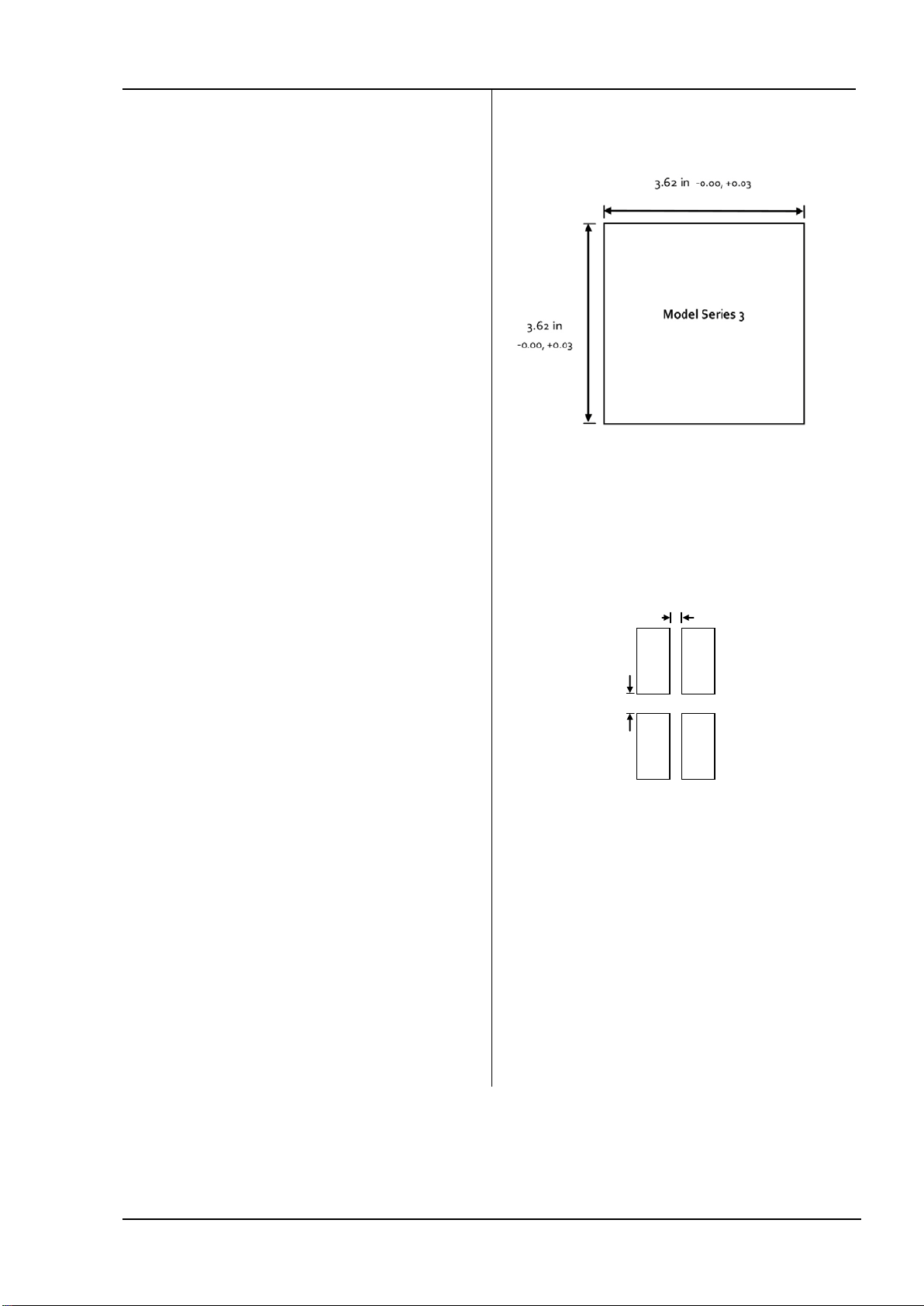
1.3.2 Panel Cut Out Sizes
1.3.3 Recommended minimum spacing of
controllers
10mm (0.4 in)
38mm (1.5 in)
(Not to scal e)
1.3.4 To Remove the Controller from its Sleeve
The controller can be unplugged from its sleeve by easing
the latching ears outwards and pulling it forward out of the
sleeve. When plugging it back into its sleeve, ensure that
the latching ears click back into place to maintain the sealing
7
Page 8
Operations Manual Series 3
!
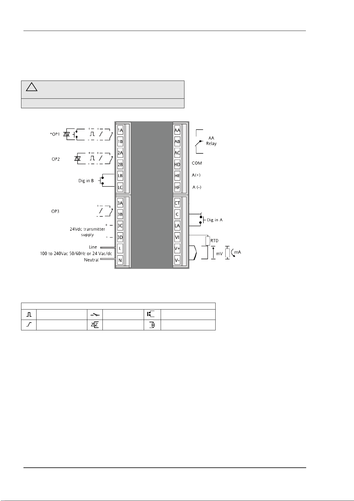
2. Step 2: Wiring
2.1 Terminal Layout Series 3 Controller
Ensure that you have the correct supply for your indicator
Key to symbols used in wiring diagrams
Logic ( SSR drive) out put
mA analogue output
Relay output
Triac output
Contact input
Current t ransformer input
8
Page 9
Series 3 Operations Manual
-
2.2 Wire Sizes
The screw terminals accept wire sizes from 0.5 to 1.5 mm (16
to 22AWG). Hinged covers prevent hands or metal making
accidental contact with live wires. The rear terminal screws
should be tightened to 0.4Nm (3.5lb in).
2.3 Precautions
• Do not run input wires together with power cables
• When shielded cable is used, it should be grounded at
one point only
• Any external components (such as zener barriers, etc)
connected between sensor and input terminals may
cause errors in measurement due to excessive and/or
un-balanced line resistance or possible leakage currents
• Not isolated from the logic outputs & digital inputs
• Pay attention to line resistance; a high line resistance
may cause measurement errors
2.4 Sensor Input (Measuring Input)
2.4.1 Thermocouple Input
+
Positive
V+
V-
Negative
-
• Use the correct compensating cable preferably shielded
2.4.2 RTD Input
VI
PRT
V+
PRT
V-
Lead compensation
• The resistance of the three wires must be the same.
The line resistance may cause errors if it is greater than
22Ω
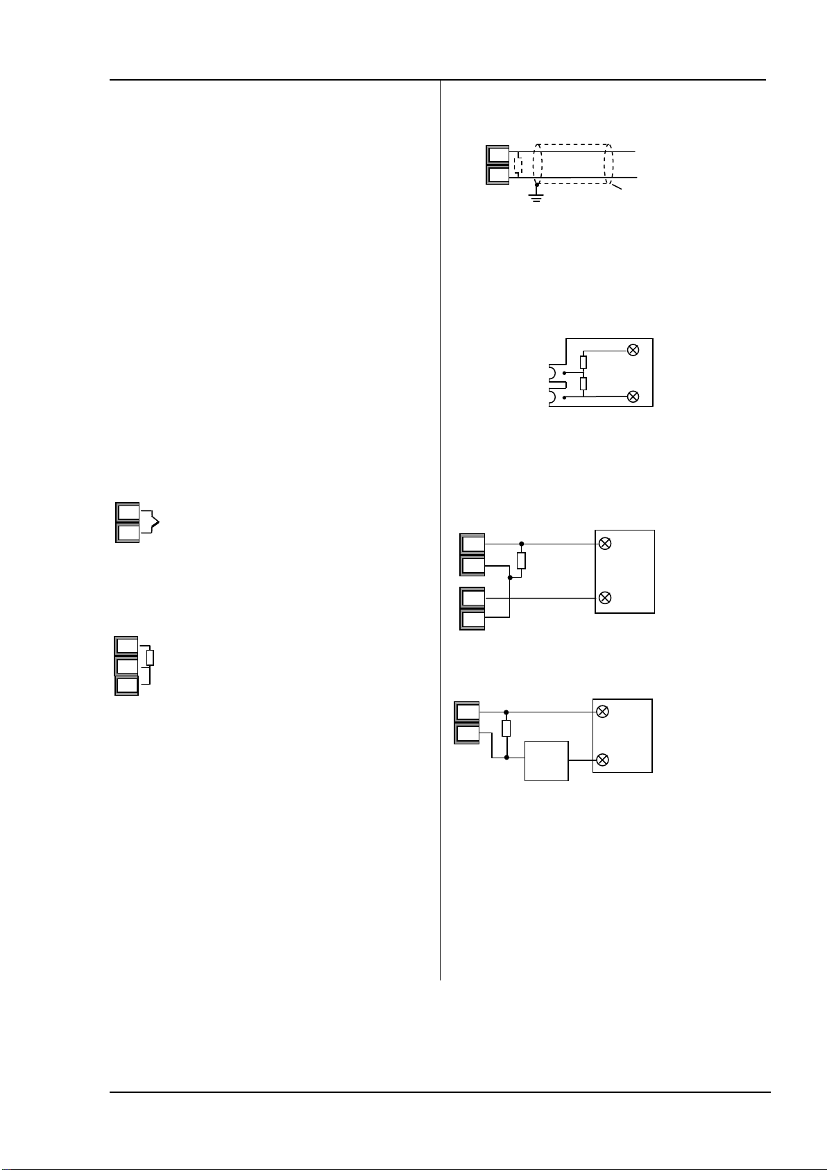
2.4.3 Linear Input (mA or mV)
V+
V-
2.49Ω
+
+
mA / mV input
-
Shield
• If shielded cable is used it should be grounded in one
place only as shown
• For a mA input connect the 2.49Ω burden resistor
supplied between the V+ and V- terminals as shown
• For a 0-10Vdc input an external input adapter is required
(not supplied).
+
-
100KΩ
806Ω
+
0-10V
Input
-
Sensor break alarm does not operate with this adaptor
fitted.
2.4.4 Two-Wire Transmitter Inputs
Using internal 2 4V power supply ( Series 3)
+
V+
-
V-
3C
3D
2.49Ω
+
-
Using external pow er supply
+
V+
-
V-
2.49Ω
-
Extern al power
supply
+
-
2-Wire
Transmitter
+
-
2-Wire
Transmitter
+
9
Page 10
Operations Manual Series 3
2.5 Input/Output 1 & Output 2
OP3
Non-isolated
OP4
Non-isolated
1A
2A
+
-
+
-
1A
+
-
+
-
+
-
These outputs can be logic (SSR drive), or relay, or mA dc. In
addition the logic output 1 can be used as a contact closure
input.
For input/output functions, see Quick Start Code in section
4.1.1.
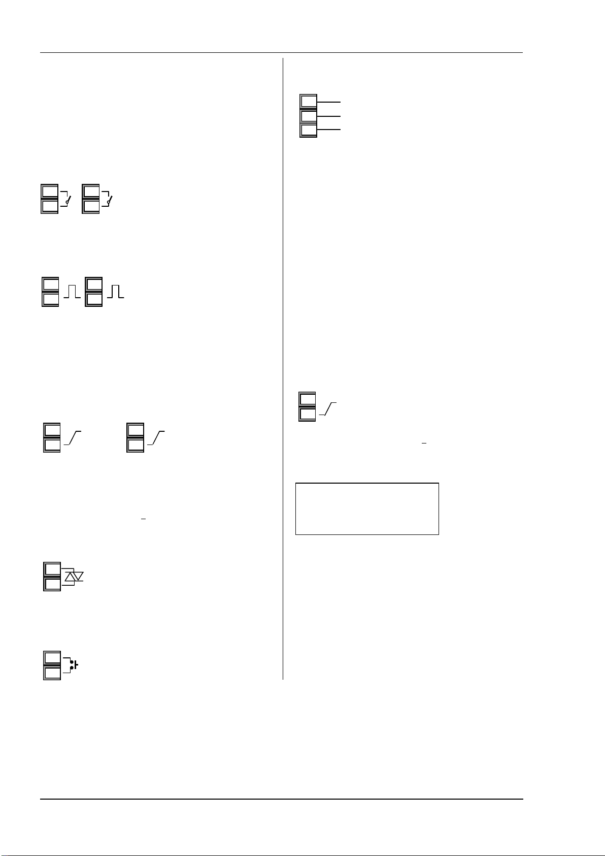
2.5.1 Relay Output (Form A, normally open)
Isolated output 240Vac CAT II
OP1 OP2
1B
2B
2.5.2 Logic (SSR drive) Output
OP1
1A
1B
OP2
2A
2B
• The output switching rate must be set to prevent
damage to the output device in use. See parameter
1.PLS or 2.PLS in section 5.
2.5.3 DC Output
OP1
1A
1B
• Not isolated from the sensor input
• Software configurable: 0-20mA or 4-20mA.
• Max load resistance: 500Ω
• Calibration accuracy: +(<1% of reading + <100µA)
2.5.4 Triac Output
•
Isolated output 240Vac CATII
1(2) A
• Rating: 0.75A rms, 30 to 264Vac resistive
1(2)B
•
• Contact rating: 2A 264Vac
resistive
Not isolated from the sensor
•
input
• Output ON state: 12Vdc at
40mA max
• Output OFF state: <300mV,
<100µA
OP2
2A
2B
2.6 Remote Setpoint Input
• There are two inputs; 4-20mA and 0-10 Volts which can be
HD
HE
HF
0-10 Volts
4-20 mA
Common
fitted in place of digital
communications
• It is not necessary to fit an
external burden resistor to the
4-20mA input
• If the 4-20mA remote setpoint input is connected and
valid (>3.5mA; < 22mA) it will be used as the main
setpoint. If it is not valid or not connected the controller
will try to use the Volts input. Volts sensor break occurs at
<-1; >+11V. The two inputs are not isolated from each
other
• If neither remote input is valid the controller will fall back
to the internal setpoint, SP1 or SP2 and flash the alarm
beacon. The alarm can also be configured to activate a
relay or read over digital communications.
• To calibrate the remote setpoint, if required, see section
15.3.5
• A local SP trim value is available in access level 3.
2.7 Output 3
Output 3 will be a mA output.
DC Output
OP3
3A
3B
• Isolated output 240Vac CAT II
• Software configurable: 0-20mA or 4-
20mA
• Max load resistance: 500Ω
• Calibration accuracy: 0.5%, +100µA
2.8 Summary of DC Outputs
OP1 Non-isolated
OP2 Non-isolated
2.5.5 Logic Contact Closure Input (I/O 1 only)
Not isolated from the sensor input
•
OP1
• Switching: 12Vdc at 40mA max
• Contact open > 500Ω. Contact closed <
1B
10
150Ω
Page 11
Series 3 Operations Manual
2.9 Output 4 (AA Relay)
Output 4 is a relay..
For output functions, see Quick Start Code in section 4.1.1.
OP4
AA
AB
AC
Relay Output (Fo rm C)
• Contact rating: 2A 264Vac resistive
2.10 General Note About Relays and
Inductive Loads
High voltage transients may occur when switching inductive
loads such as some contactors or solenoid valves. Through
the internal contacts, these transients may introduce
disturbances which could affect the performance of the
instrument.
For this type of load it is recommended that a ‘snubber’ is
connected across the normally open contact of the relay
switching the load. The snubber recommended consists of a
series connected resistor/capacitor (typically 15nF/100Ω). A
snubber will also prolong the life of the relay contacts.
A snubber should also be connected across the output
terminal of a triac output to prevent false triggering under
line transient conditions.
WARNING
When the relay contact is open or it is connected to a high
impedance load, the snubber passes a current (typically
0.6mA at 110Vac and 1.2mA at 240Vac). You must ensure
that this current will not hold on low power electrical
loads. If the load is of this type the snubber should not be
connected.
• Isolated output 240Vac CAT II
• Output: 24Vdc, +/- 10%. 28mA max.
• inside the controller
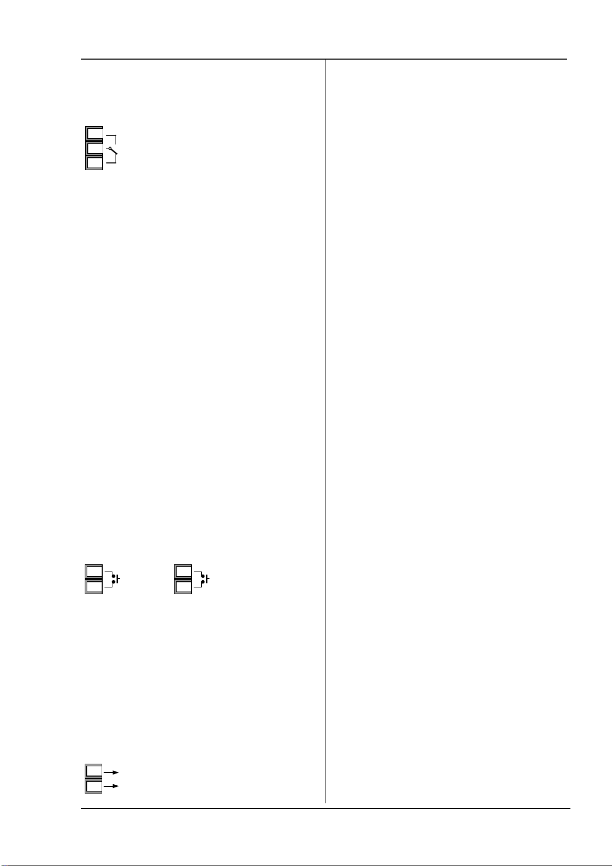
2.11 Digital Inputs A & B
Digital input A is an optional input in model Series 3. Digital
input B is always fitted in model Series 3.
Dig in A
C
LA
Dig in B
LB
LC
• Not isolated from the current transformer input or the
sensor input
• Switching: 12Vdc at 40mA max
• Contact open > 500Ω. Contact closed < 200Ω
• Input functions: Please refer to the list in the quick
codes.
2.12 Transmitter Power Supply
The Transmitter is fitted as standard in model Series 3.
Transmi tter Supply
3C
3D
24Vdc
11
Page 12
Operations Manual Series 3
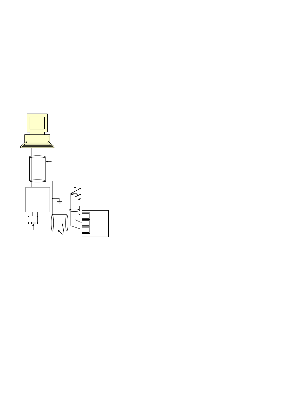
2.13 Digital Communications
Optional.
Digital communications uses the Modbus protocol. The
interface comes standard as EIA485 (2-wire).
Digital communications is not available if Remote
Setpoint is fitted
Cable screen should be grounded at one point only to
prevent earth loops.
• Isolated 240Vac CAT II.
EIA485 Connections
Rx Tx Com
Tx Rx Com
RxB/
TxB
*
RxA/
TxA
220Ω termination
resist or
Com
* EIA2 32/EIA485 2-wire
communicat ions convert er eg
Type K D485
Screen
220Ω termination
resistor on last
controller in the line
Twis ted pair
Daisy Chain to
further
controllers
HD
Common
HE
Rx A(+)
HF
Tx B(-)
12
Page 13

Series 3 Operations Manual
AA
2.14 Controller Power Supply
1. Before connecting the instrument to the power line,
make sure that the line voltage corresponds to the
description on the identification label.
2. Use copper conductors only.
3. For 24V the polarity is not important
4. The power supply input is not fuse protected. This
should be provided externally
Power Supply
L
Line
N
• High voltage supply: 100 to 240Vac, -15%, +10%, 48 to
• Recommended external fuse ratings are as follows:
Neutral
62 Hz
For 100-240Vac, fuse type: T rated 2A 250V.
2.15 Example Heat/Cool Wiring Diagram
This example shows a heat/cool temperature controller
where the heater control uses a SSR and the cooling control
uses a relay.
L
Heater
fuse
Solid State Relay
(e.g. TE10)
N
Heater
Controller fuse
1A
1B
2A
2B
L
N
J
CT
AB
C
AC
LA
VI
HD
V+
HE
V-
HF
J
+
-
T/C
Relay
output
fuse
Snubber*
Cooling or
alarm relay
Safety requirements for permanently connected equipment
state:
• A switch or circuit breaker shall be included in the
building installation
• It shall be in close proximity to the equipment and
within easy reach of the operator
• It shall be marked as the disconnecting device for the
equipment
A single switch or circuit breaker can drive more than
one instrument
13
Page 14

Operations Manual Series 3
3. Safety and EMC Information
This controller is intended for industrial temperature and
process control applications when it will meet the
requirements of the European Directives on Safety and
EMC. Use in other applications, or failure to observe the
installation instructions of this handbook may impair safety
or EMC. The installer must ensure the safety and EMC of
any particular installation.
Safety
This controller complies with the European Low Voltage
Directive 73/23/EEC, by the application of the safety
standard EN 61010.
Electromagnetic compatibility
This controller conforms with the essential protection
requirements of the EMC Directive 89/336/EEC, by the
application of a Technical Construction File. This instrument
satisfies the general requirements of the industrial
environment defined in EN 61326. For more information on
product compliance refer to the Technical Construction File.
GENERAL
The information contained in this manual is subject to
change without notice. While every effort has been made to
ensure the accuracy of the information, your supplier shall
not be held liable for errors contained herein.
Unpacking and storage
The packaging should contain an instrument mounted in its
sleeve, two mounting brackets for panel installation and an
Installation & Operating guide.
If on receipt, the packaging or the instrument are damaged,
do not install the product but contact Super Systems, Inc. If
the instrument is to be stored before use, protect from
humidity and dust in an ambient temperature range of -30oC
o
to +75
C.
SERVICE AND REPAIR
This controller has no user serviceable parts. Contact Super
Systems, Inc. for repair.
Caution: Charged capacitors
Before removing an instrument from its sleeve, disconnect
the supply and wait at least two minutes to allow capacitors
to discharge. It may be convenient to partially withdraw the
instrument from the sleeve, then pause before completing
the removal. In any case, avoid touching the exposed
electronics of an instrument when withdrawing it from the
sleeve.
Failure to observe these precautions may cause damage to
components of the instrument or some discomfort to the
user.
Electrostatic discharge precautions
When the controller is removed from its sleeve, some of the
exposed electronic components are vulnerable to damage by
electrostatic discharge from someone handling the
controller. To avoid this, before handling the unplugged
controller discharge yourself to ground.
Cleaning
Do not use water or water based products to clean labels or
they will become illegible. Isopropyl alcohol may be used to
clean labels. A mild soap solution may be used to clean
other exterior surfaces of the product.
3.1 Installation Safety Requirements
Safety Symbols
Various symbols may be used on the controller. They have
the following meaning:
Caution, (refer to
!
accompanying documents )
Equipm ent protect ed
throughout by DOU BLE
INSULATION
Helpful hints
Personnel
Installation must only be carried out by suitably qualified
personnel in accordance with the instructions in this
handbook.
Enclosure of Live Parts
To prevent hands or metal tools touching parts that may be
electrically live, the controller must be enclosed in an
enclosure.
Caution: Live sensors
The controller is designed to operate if the temperature
sensor is connected directly to an electrical heating element.
However you must ensure that service personnel do not
touch connections to these inputs while they are live. With a
live sensor, all cables, connectors and switches for
connecting the sensor must be mains rated.
Wiring
It is important to connect the controller in accordance with
the wiring data given in this guide. Take particular care not
to connect AC supplies to the low voltage sensor input or
other low level inputs and outputs. Only use copper
conductors for connections (except thermocouple inputs)
and ensure that the wiring of installations comply with all
local wiring regulations. For example in the UK use the
latest version of the IEE wiring regulations, (BS7671). In the
USA use NEC Class 1 wiring methods.
Power Isolation
The installation must include a power isolating switch or
circuit breaker. This device should be in close proximity to
the controller, within easy reach of the operator and marked
as the disconnecting device for the instrument.
Overcurrent protection
The power supply to the system should be fused
appropriately to protect the cabling to the units.
14
Page 15

Series 3 Operations Manual
Voltage rating
The maximum continuous voltage applied between any of
the following terminals must not exceed 264Vac:
• relay output to logic, dc or sensor connections;
• any connection to ground.
The controller must not be wired to a three phase supply
with an unearthed star connection. Under fault conditions
such a supply could rise above 264Vac with respect to
ground and the product would not be safe.
Conductive pollution
Electrically conductive pollution must be excluded from the
cabinet in which the controller is mounted. For example,
carbon dust is a form of electrically conductive pollution. To
secure a suitable atmosphere in conditions of conductive
pollution, fit an air filter to the air intake of the cabinet.
Where condensation is likely, for example at low
temperatures, include a thermostatically controlled heater in
the cabinet.
This produ ct has been designed to conform to BS EN61010
installat ion category II, pol lution degree 2 . These are defined as
follows:
Installation Category II (CAT II)
The rated impulse voltage for equipment on nominal 230V supply
is 2500V.
Pollution Degree 2
Normally only non conductive pollution occurs. Occasionally,
independent temperature sensor, which will isolate the
heating circuit.
Please note that the alarm relays within the controller will
not give protection under all failure conditions.
Routing of wires
To minimise the pick-up of electrical noise, the low voltage
DC connections and the sensor input wiring should be routed
away from high-current power cables. Where it is
impractical to do this, use shielded cables with the shield
grounded at both ends. In general keep cable lengths to a
minimum.
however, a temporary conductivity caused by condensation shall
be expected.
Grounding of the temperature sensor shield
In some installations it is common practice to replace the
temperature sensor while the controller is still powered up.
Under these conditions, as additional protection against
electric shock, we recommend that the shield of the
temperature sensor is grounded. Do not rely on grounding
through the framework of the machine.
Over-temperature protection
When designing any control system it is essential to consider
what will happen if any part of the system should fail. In
temperature control applications the primary danger is that
the heating will remain constantly on. Apart from spoiling
the product, this could damage any process machinery being
controlled, or even cause a fire.
Reasons why the heating might remain constantly on
include:
• the temperature sensor becoming detached from the
process
• thermocouple wiring becoming short circuit;
• the controller failing with its heating output constantly
on
• an external valve or contactor sticking in the heating
condition
• the controller setpoint set too high.
Where damage or injury is possible, we recommend fitting a
separate over-temperature protection unit, with an
15
Page 16
Operations Manual Series 3
4. Switch On
!
The way in which the controller starts up depends on factors
described below in sections 4.1, 4.2 and 4.3.
4.1 New Controller
If the controller is new AND has not previously been
configured it will start up showing the ‘Quick Configuration’
codes. This is a built in tool which enables you to configure
the input type and range, the output functions and the
display format.
Adjust these as follows:.
1. Press any button. The characters will change to ‘-‘, the
first one flashing.
or
2. Press
to change the flashing character to the
required code shown in the quick code tables – see
below. Note: An
x indicates that the option is not
fitted.
3. Press to scroll to the next character.
You cannot scroll to the next character until the current
character is configured.
Incorrect configuration can result in damage to the
process and/or personal injury and must be carried out by a
competent person authorised to do so. It is the
responsibility of the person commissioning the controller to
ensure the configuration is correct
To return to the first character press
4. When all five characters have been configured the
display will go to Set 2.
5. When the last digit has been entered press
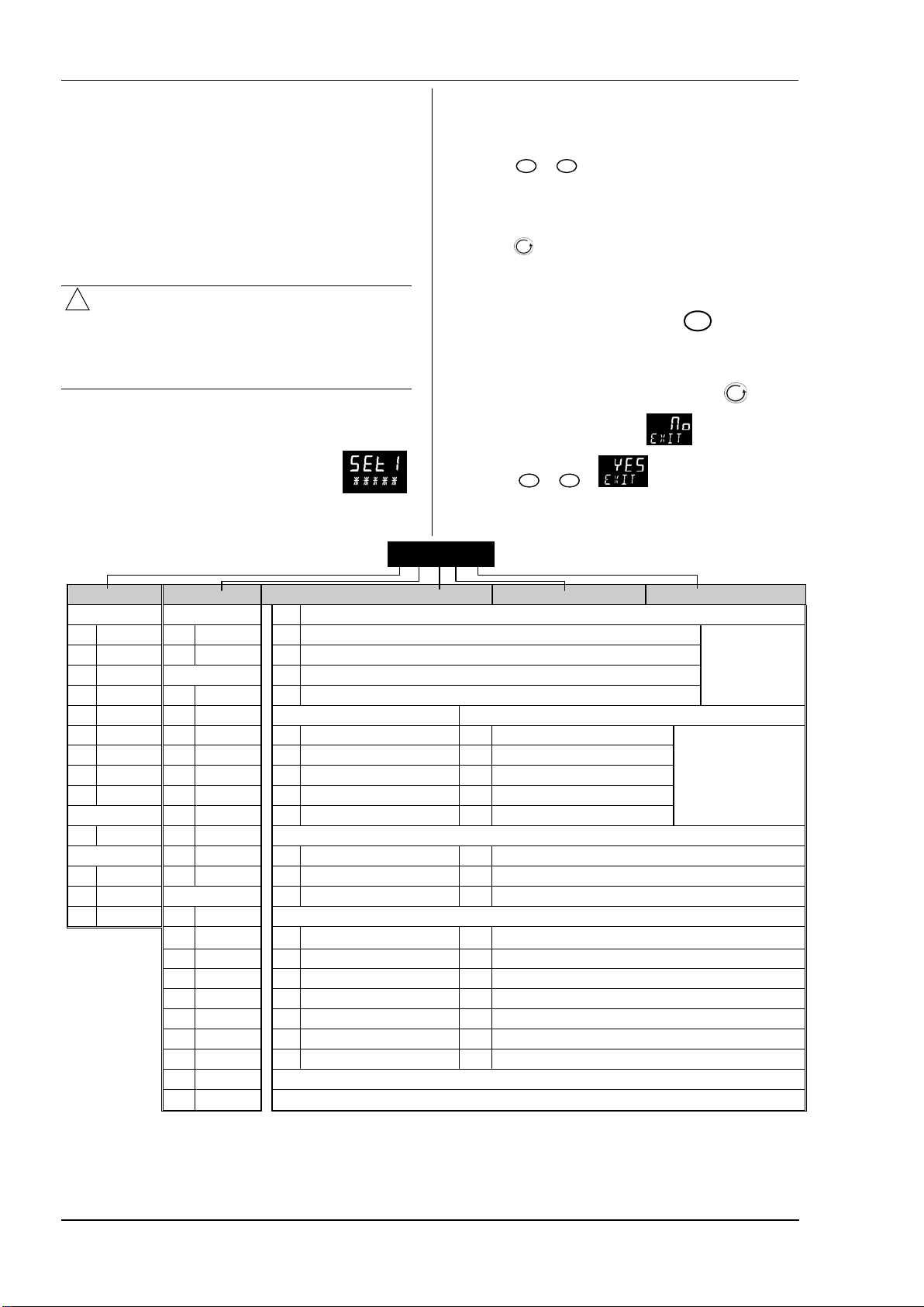
4.1.1 Quick Start Code
The quick start code consists of two ‘SETS’ of
five characters. The upper section of the
display shows the set selected, the lower
section shows the five digits which make up
the set.
SET 1
Input ty pe Range Input/O utput 1 Output 2 Output 4
Thermocouple Full range X Unconfigured
B Ty pe B C
J Type J F
K Type K Centigra de J ON/OF F Heating [logic or relay (1)], or PI D 0-20mA heating
L Type L 0 0-100 K ON/OF F Cooling [logic or relay (1)], or P ID 0-20mA cooling
N Type N 1 0-200 Alarm (2): energised in alarm Alar m (2): de-energised in alarm
R Type R 2 0 -400 0 High alarm 5 High alarm Note (2)
S Type S 3 0-600 1 Low alarm 6 Low alarm
T T ype T 4 0-800 2 Deviation high 7 Dev iation high
C Custom 5 0-1000 3 Deviation low 8 Deviat ion low
RTD 6 0-1200 4 D eviation band 9 Deviat ion band
P Pt100 7 0-1400 DC Retransmission (no t O/P4)
Linear 8 0-1600 D 4-20mA Setpoint N 0-20mA Setpoint
M 0-80mV 9 0-1800 E 4-20mA Temperature Y 0-20m A Temperatu re
2 0-20mA Fahrenheit F 4-20mA output Z 0 -20mA output
4 4-20mA G 32-212 Logic input functions ( Input/Output 1 only)
H 32-392 W Alarm acknowledge V Recipe 2/1 select
J 32-752 M Manual select A Remote UP button
K 32-1112 R FEATURE UNAVAILABLE B Remote DOWN button
L 32-1472 L K eylock G FEATURE UNAVAILABLE
M 32-1832 P Setpoint 2 s elect I FEATURE UNAVAILABLE
o
o
N 32-21 92 T FEATURE UNAVAILABLE Q Standby select
P 32-2552 U Remot e SP enable
R 32-2912
T 32-3272
C H PID H eating [ logic, relay (1) or 4-20mA] or motor valve open [VC and VP only] Note (1) O/P4 is relay
F C PID Cooling [logic, relay (1) or 4-20mA] or motor valve close [VC and VP only]
KCHC0
again, the display will show
6. Press
The controller will then automatically go to the operator
level.
or
to .
OP1 = alarm 1
OP2 = alarm 2
OP3 = alarm 3
OP4 = alarm 4
only.
16
Page 17
Series 3 Operations Manual
SET 2
1 WRDT
Input CT Scaling Digital In put A Digita l Input B (2) Output 3 (2) Lo wer Display
Unconfigured
X
10 Amps
1
25 Amps
2
50 Amps
5
100 Amps
6
Note (1)
X
W Alarm acknowledg e H PI D heating or motor valve open (3) P Output
M M anual select C PID cooling or motor valve close (3) R Time remaining
R FEATURE UNAVAILABLE J ON/OFF heating (not show n if VC or VP) E Elapsed time
L Keylock K ON/OFF cooling (not shown if VC or VP) 1 Alarm setpoint
P Setpoint 2 select Alarm Outputs (1) A Load Amps
T FEATURE UNAVAILABLE Energised in alarm De-energised in alarm D D well/Ramp
OP1 = alarm 1 (I/O1)
OP2 = alarm 2
V Recipe 2 /1 select 1 Low alarm 6 Low alarm N None
OP3 = alarm 3
B Remote DOWN button 3 Dev L ow 8 Dev L ow Output meter (2)
OP4 = alarm 4 (AA)
Note (3)
VP, VC o nly
G FEATURE UNAVAILABLE 4 D ev Band 9 Dev Band M Setpoint with
I FEATURE UNAVAILABLE DC outputs Am meter (2)
Q St andby select H 4-20mA heating
C 4-20mA cooling
K 0-20mA cooling
Retransmission output
D 4-20 Setp oint
E 4-20 Measured Temperat ure
F 4-20mA output
N 0-20 Setpoint
Y 0-20 M easured Temp erature
Z 0-20mA output
4.2 To Re-Enter Quick Code mode
If you need to re-enter the ‘Quick Configuration’ mode this
can always be done as follows:
1. Power down the controller
Unconfigured
U Rem ote SP enable 0 High alarm 5 High alarm T ime/Target
A Remote UP button 2 Dev High 7 Dev High C Setpoint with
X Unconfigured T Setpoint (std)
J 0-20mA heating
4.3 Pre-Configured Controller or
Subsequent Starts
A brief start up sequence consists of a self test during which
the software version number is shown followed briefly by the
quick start codes.
2. Hold down the
controller again.
3. Keep the button pressed until code is displayed.
4. Enter the configuration code (this is defaulted to 4 in a
new controller)
5. The quick start codes may then be set as described
previously
Parameters may also be configured using a deeper level
of access. This is described in later chapters of this
handbook.
If the controller is started with the
down, as described above, and the quick start codes are
shown with dots (e.g. J.C.X.X.X), this indicates that the
controller has been re-configured in a deeper level of access
and, therefore, the quick start codes may not be valid. If the
quick start codes are accepted by scrolling to then
the quick start codes are reinstated.
button, and power up the
button held
It will then proceed to Operator Level 1..
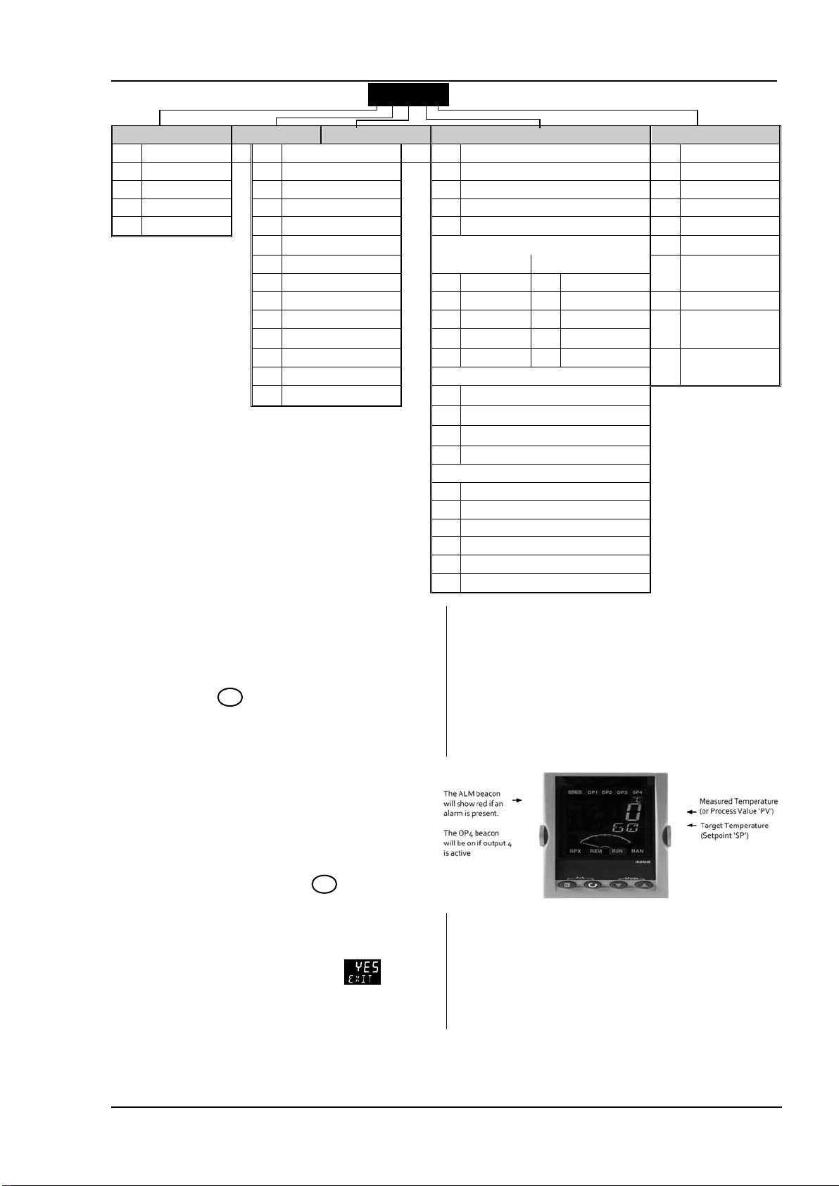
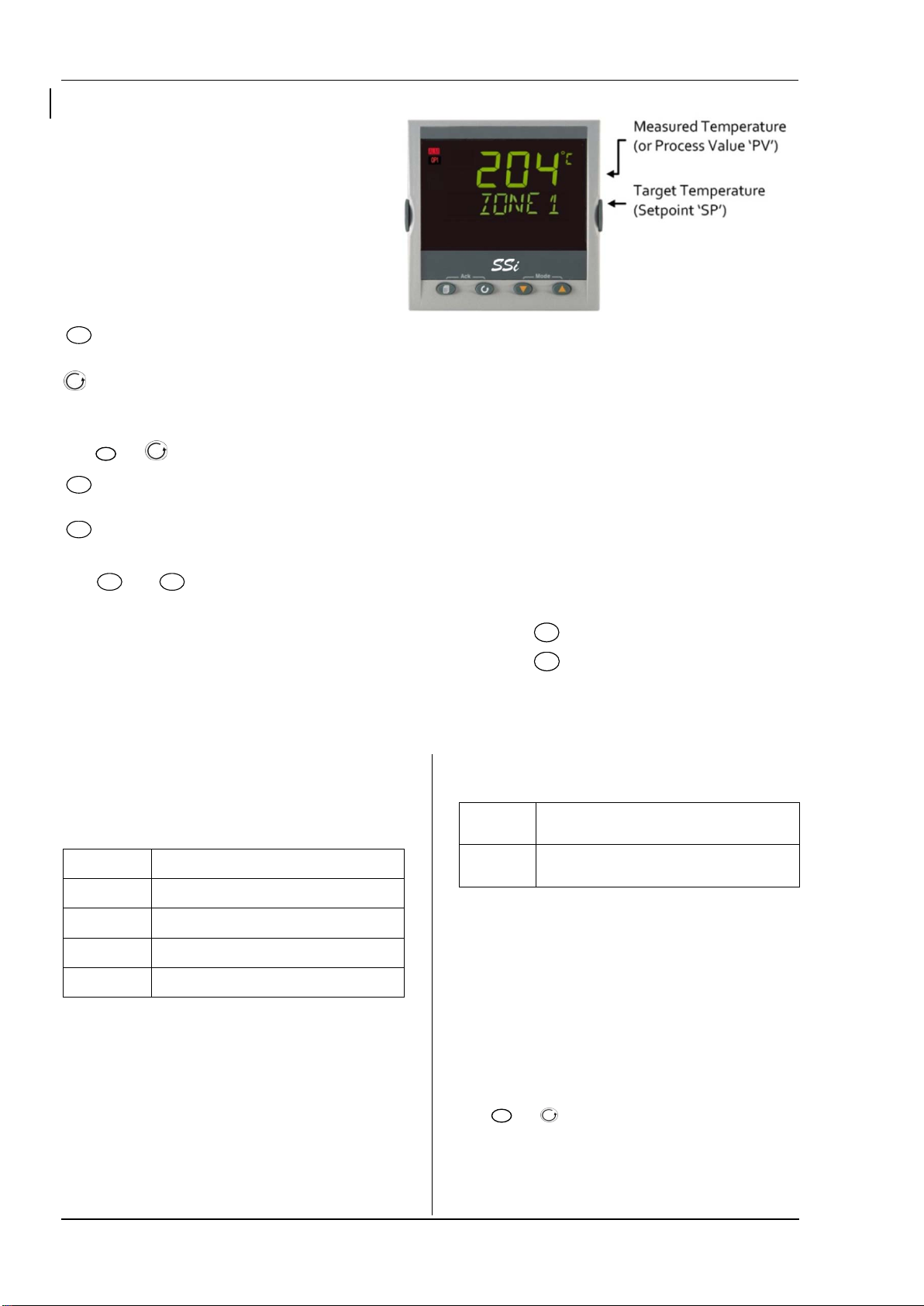
You will see the display shown below. It is called the HOME
display.
If the quick start codes do not appear during this start up,
it means that the controller has been configured in a deeper
level of access, see the note in section 4.2. The quick start
codes may then not be valid and are therefore not shown.
17
Page 18
Operations Manual Series 3
4.4 Front Panel Layout
ALM Alarm active (Red)
OP1 lit when output 1 is ON
OP2 lit when output 2 is ON
OP3 lit when output 3 is ON
OP4 lit when output 4 relay is ON
SPX Alternative setpoint in use (e.g. setpoint 2)
REM Remote digital setpoint. Also flashes when digital
communications active
MAN Manual mode selected
Operator Buttons:
Referred to as the ‘page’ button. From any view -
press to return to the HOME display
Referred to as the ‘scroll’ button. Press to select a new
parameter. If held down it will continuously scroll through
parameters.
Press
decrease a value
a value
Press
and Manual mode.
and (ACK) together to acknowledge an alarm.
Referred to as the ‘arrow down’ button. Press to
Referred to as the ‘arrow up’ button. Press to increase
and
(MODE) together to toggle between Auto
4.4.1 To Set The Target Temperature.
From the HOME display:
Press
Press
The new setpoint is entered when the button is released
and is indicated by a brief flash of display.
to raise the setpoint
to lower the setpoint
4.4.2 Alarms
Process alarms may be configured using the Quick Start
Codes. Each alarm can be configured for:
Full Scale Low The alarm is shown if the proces s value falls below a
set t hreshold
Full Scale High The alarm is shown if t he process value rises above a
set t hreshold
Deviation Low The alarm is shown if the process value deviates below
the setpoint by a set threshold
Deviation High The alarm is s hown if the process valu e deviates above
the setpoint by a set threshold
Deviation Band The alarm is s hown if the process value deviates abov e
or below t he setpoint by a set threshold
If an alarm is not configured it is not shown in the list of
level 2 parameters.
Additional alarm messages may be shown such as
CONTROL LOOP BROKEN. This occurs if the controller
does not detect a change in process value following a
From firmware version 2.11 two further alarm types
have been made available. These are:
Rising rat e of
change
Falling rat e of
change
These alarms cannot be configured by the Quick Start Code
– they can only be configured in Configuration Mode..
4.4.3 Alarm Indication
If an alarm occurs, the red ALM beacon will flash. A
scrolling text message will describe the source of the alarm.
Any output (usually a relay) attached to the alarm will
operate. An alarm relay can be configured using the Quick
Start Codes to be energised or de-energised in the alarm
condition. It is normal to configure the relay to be deenergised in alarm so that an alarm is indicated if power to
the controller fails.
An alarm will be det ected if the rat e of change
(unit s/minute) in a positive direct ion exceeds the alarm
threshold
An alarm will be det ected if the rat e of change
(units/m inute) in a negativ e direction exceeds the alarm
threshold
change in output demand after a suitable delay time.
Another alarm message may be INPUT SENSOR BROKEN
(SBr). This occurs if the sensor becomes open circuit; the
output level will adopt a ‘SAFE’ value which can be set up in
Operator Level 3..
Press
If the alarm is still present the ALM beacon will light
continuously otherwise it will go off.
The action which takes place depends on the type of alarm
and (ACK) together to acknowledge an alarm.
configured:
18
Page 19

Series 3 Operations Manual
Non
latching
A non latching alarm will reset itself when
the alarm condition is removed. By default
alarms are configured as non-latching, deenergised in alarm.
Auto
Latching
An auto latching alarm requires
acknowledgement before it is reset. The
acknowledgement can occur BEFORE the
condition causing the alarm is removed.
Manual
Latching
The alarm continues to be active until both
the alarm condition is removed AND the
alarm is acknowledged. The
acknowledgement can only occur AFTER
the condition causing the alarm is
removed.
By default alarms are configured as non-latching, deenergised in alarm. To configure latched alarms, refer to
section 12.3.1.
19
Page 20
Operations Manual Series 3
4.4.4 Auto, Manual and Off Mode
!
The controller can be put into Auto, Manual or Off mode –
see next section.
Auto mode is the normal operation where the output is
adjusted automatically by the controller in response to
changes in the measured temperature.
In Auto mode all the alarms and the special functions (auto
tuning, soft start) are operative
Manual mode means that the controller output power is
manually set by the operator. The input sensor is still
connected and reading the temperature but the control
loop is ‘open’.
In manual mode the MAN beacon will be lit, Band and
deviation alarm are masked
The power output can be continuously increased or
decreased using the
Manual mode must be used with care. The power
level must not be set and left at a value that can damage
the process or cause over-heating. The use of a separate
‘over-temperature’ controller is recommended.
Off mode means that the heating and cooling outputs are
turned off. The process alarm and analogue retransmission
outputs will, however, still be active while Band and
deviation alarm will be OFF.
or
buttons.
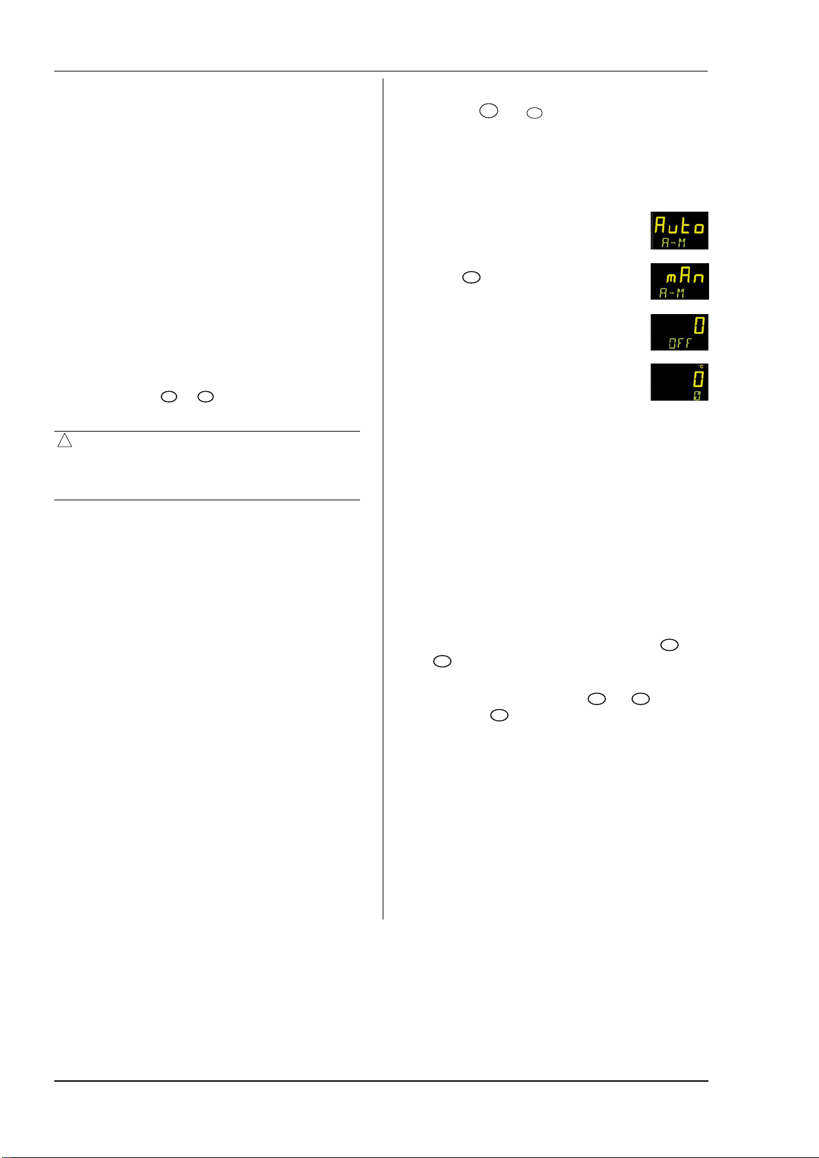
4.4.5 To Select Auto, Manual or Off Mode
Press and hold
second.
This can only be accessed from the HOME display.
1. Auto’ is shown in the upper display.
After 5 seconds the lower display will
scroll the longer description of this
parameter. ie ’ loop mode – auto
manual off’
2. Press
to select ‘OFF’. This is shown in the
upper display.
3. When the desired Mode is selected, do
not push any other button. After 2
seconds the controller will return to the
HOME display.
4. If OFF has been selected, OFF will be
shown in the lower display and the heating and cooling
outputs will be off
5. If manual mode has been selected, the MAN beacon
will light. The upper display shows the measured
temperature and the lower display the demanded
output power.
and
(Mode) together for more than 1
to select ‘mAn’. Press again
+
+
The transfer from Auto to manual mode is ‘bumpless’.
This means the output will remain at the current value
at the point of transfer. Similarly when transferring
from Manual to Auto mode, the current value will be
used. This will then slowly change to the value
demanded automatically by the controller.
6. To manually change the power output, press
to lower or raise the output. The output power is
continuously updated when these buttons are pressed
7. To return to Auto mode, press
Then press
to select ‘Auto’.
and
or
together.
20
Page 21
Series 3 Operations Manual
4.4.6 Level 1 Operator Parameters
A minimal list of parameters are available in operator Level
1 which is designed for day to day operation. Access to
these parameters is not protected by a pass code.
Press to step through the list of parameters. The
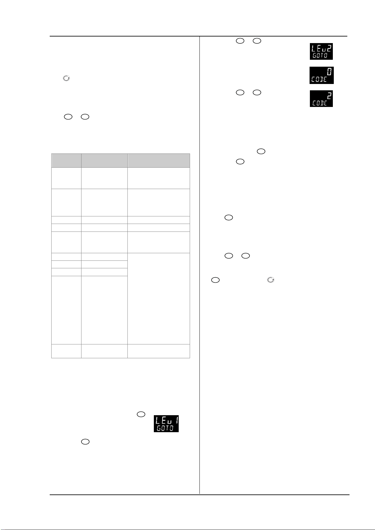
4. Press
choose Lev 2 (Level 2)
5. After 2 seconds the
display will show
or
to
mnemonic of the parameter is shown in the lower display.
After five seconds a scrolling text description of the
parameter appears.
The value of the parameter is shown in the upper display.
Press
for 30 seconds the controller returns to the HOME display
or
to adjust this value. If no key is pressed
The parameters that appear depend upon the functions
configured. They are:
Parameter
Mnemonic
WRK.OP WORKING OU TPUT
WKG.SP WORKING
SP1 SETPOINT 1 Alterable
SP2 SETPOINT 2 Alterable
T.REMN TIME REM AINING
A1.xxx ALARM 1 SETPOINT Read only.
A2.xxx ALARM 2 SETPOINT
A3.xxx ALARM 3 SETPOINT
A4.xxx ALARM 3 SETPOINT
LD.AMP LOAD CURRENT Read only. On ly shown if CT
Scrolling Display
and Description
The active output
value
SETPOINT
The active setpoint
value.
Time to end of set
period
Alterability
Read only.
Appears when the controller
is in AUTO or OFF mode.
Read only.
Only shown when the
controller is in MAN or OFF
mode.
Read only
0:00 to 9 9.59 hh:mm or
mm:ss
Only shown if the alarm is
configured.
xxx = alarm type as follows:
HI = High alarm
LO = Low alarm
d.HI = Deviatio n high
d.LO = Deviation low
d.HI = Deviatio n high
rrc = Rising ra te of change
(unit s/minute)
Frc = Falling rate of chan ge
(unit s/minute)
is configured
6. Press
or
to enter the
pass code. Default = ‘2’
• If an incorrect code is entered the controller reverts to
Level 1.
5.2 To Return to Level 1
1. Press and hold
2. Press
to select LEv 1
The controller will return to the level 1 HOME display.
Note: A security code is not required when going from a
higher level to a lower level.
5.3 Level 2 Parameters
Press
mnemonic of the parameter is shown in the lower display.
After five seconds a scrolling text description of the
parameter appears.
The value of the parameter is shown in the upper display.
Press
for 30 seconds the controller returns to the HOME display
Backscroll is achieved when you are in this list by pressing
The following table shows a list of parameters available in
Level 2.
to step through the list of parameters. The
or
to adjust this value. If no key is pressed
while holding down .
5. Operator Level 2
Level 2 provides access to additional parameters. Access to
these is protected by a security code.
5.1 To Enter Level 2
1. From any display press and hold
2. After a few seconds the display will
show
3. Release
.
(If no button is pressed for about 45 seconds the display
returns to the HOME display)
21
.
Page 22

Operations Manual Series 3
Mnemonic Scrolling Display and description Range
WKG.SP
WORKING SETPOINT is the active setpoint value and appears when the controller is
SP.HI to SP.LO
in Manual mode. It may be derived from SP1 o r SP2, or, if t he cont roller is ramp ing
(see SP.RAT), it is the current ramp value.
WRK.OP WORKING OUTPUT is the output from the controller expressed as a percentage of
full output. It ap pears when the controller is in Auto mode.
For a time proportioning output, 50% = relay or logic output on or off for equal
lengths of time.
For On/Off control: OFF = <1%. ON = >1 %
Read only value
0 to 100% for heatin g
0 to –100% for cooling
-100 (max c ooling) to 100% (max
heating
T.STAT FEATURE UNAVAILABLE Reset rES
Running run
Hold hoLd
End Timed out
UNITS DISPLAY UNITS Temperature display units. ‘Percentage’ is provided for linear
input s
O
C Degrees C
O
F Degrees F
O
k Degrees K
nonE
PErc
None
Percentage
SP.HI SETPOINT HIGH High set point limit applied to SP1 and SP2. Alterable between range limits
SP.LO SETPOINT LOW Low setpoint limit applied to SP1 and SP2
By default the remote setpoint is scaled between SP.HI and SP.LO. Two further parameters (REM.HI and REM.LO) are
available in access level 3 to limit the Remote SP range if req uired.
SP1 SETPOINT 1 allows control setpoint 1 value to be adjusted Alterable: SP.HI to SP.LO
SP2 SETPOINT 2 allows cont rol setpoint 2 value to be adjusted
Alterable: SP.HI to SP.LO
SP.RAT SETPOINT RATE LIMIT Rate of change of setpoint value. OFF to 3000 display units per
minute
The next section applies to the Timer only.
TM.CFG FEATURE UNAVAILABLE none None
Dwel
DeLy
sfst
Dwell
Delayed switch on
Soft start
TM.RES FEATURE UNAVAILABLE Hour
min
THRES FEATURE UNAVAILABLE
OFF or 1 to 3000
END.T FEATURE UNAVAILABLE OFF
Dwel
SP2
Hours
Minutes
Control OP goes to zero
Control continues at SP1
Go to SP2
SS.PWR FEATURE UNAVAILABLE -100 to 100%
SS.SP FEATURE UNAVAILABLE
DWELL FEATURE UNAVAILABLE
T.REMN FEATURE UNAVAILABLE
Between SP.HI and SP.LO
0:00 to 9 9.59 hh :mm: or mm:ss
0:00 to 99.59 hh:mm: or mm:ss
The following parameters are available when the timer is configured as a programmer.
SERVO FEATURE UNAVAILABLE SP
PV
SP.rb
PV.rb
Setpoint
Process variable
Ramp back to SP
Ramp back to PV
TSP.1 TARGET SETPOINT 1. To set the target value for the first setpoint
RMP.1 FEAT URE UNAVAILABLE OFF, 0:01 to 3000 units per min or
hour as set by
TM.RES
22
Page 23

Series 3 Operations Manual
!
Mnemonic Scrolling Display and description Range
DWEL.1 FEATURE UNAVAILABLE OFF, 0:01 to 99:59 hh:mm or
The above three parameters are repeated for the next three program segments, i.e. TSP.2 (3 & 4), RMP.2 (3 & 4), DWEL.2 (3 & 4)
This section applies to Alarms only If an alarm is not configured the parameters do not appear
A1.--- - to A4.-
--
A.TUNE AUTOTUNE automatically sets the control parameters to match the process
PB PROPORTIONAL BAND sets an output which is proportional to the size of the error
TI INTEGRAL TIME removes steady state control offsets by ramping the output up or
TD DERIVATIVE TIME determines how strongly the controller will reac t to the rate of
MR MANUAL RESET applies to a PD on ly controller i.e. the integral term is turned off.
R2G RELATIVE COOL GAIN adjusts the cooling proportional band relative to the heating
HYST.H HEATING HYSTERESIS Sets the difference in temperature units between heating
HYST.C COOLING HYSTERESIS Sets the difference in temperature units between cooling
D.BAND CHANNEL 2 DEADBAND adjusts a zone between heating and cooling outputs when
OP.HI OUTPUT HIGH limits the maximum heating power applied to the process or a
1. (2, 3 or 4)
PLS.
LD.AMP LOAD CURRENT is the measured load current when the power demand is on CT Range
LK.AMP LEAK CURRENT is the measured leakage current when the power demand is off.
LD.ALM LOAD CURRENT THRESHOLD Sets a low alarm on the load current measured by
LK.ALM LEAK CURRENT THRESHOLD sets a high alarm on the leakage current measured by
HC.ALM OVERCURRENT THRESHOLD Sets a high alarm on the load current measured by
ADDR ADDRESS - communications address of the controller. 1 to 254
HOME HOME DISPLAY Defines the parameter which appears in the lower section of the STD Standard
ALARM 1 (2, 3 or 4) SETPOINT sets the threshold value at which an alarm occurs.
Up to four alarms are available and are only shown if configured.
The last three characters in the mnemonic specify the alarm type:
Lo Full Scale Low Hi Full Scale High
dHi Deviation H igh dLo Deviation Low Bnd Deviation Band
rrc Rising rate of
change
This section applies to control the parameters. A further description of theses parameters is given in section 11
characteristics.
signal. Units may be % or display units.
down in proportion to the amplitude and duration of the error signal.
change in the process value. It is used to prevent overshoot and undershoot and to
restore the PV rapidly if there is a sudden change in demand.
Set this to a value of power output (from +100% heat, to -100% cool which removes
any steady state error between SP and PV.
proportional band. Particularly necessary if the rate of heating and rate of cooling are
very different. (Heat/Cool only)
turning off and turning on when ON’OFF control is used. Only appears if channel
1(heating) control action is On/Off
turning off and turning on when ON/OFF control is used. Only appears if channel 2
(cooling) control action is On/Off
neither output is on. Off = no deadband. 100 = heating and cooling off.
Only appears if On/Off control configured.
minimum cooling output.
OUTPUT 1 (2, 3 or 4) MINIMUM PULSE TIME Sets the minimum on an d off time for
the control output.
Ensure this parameter is set to a value that is suitable for the output
switching device in use. For example, if a logic output is used to switch a small
relay, set the value to 5.0 seconds or greater to prevent damage to the device due
to rapid switching.
This section applies to current transformer input only. The CT option is not available on the Series 3.
the CT. Used to detect partial load failure.
the CT.
the CT
Frc Falling rate of
change
mm:ss as set by
SP.HI to SP.LO
1 to 9999 units/minute
Off
On
1 to 9999 display units
Default 20
Off to 9999 seconds
Default 36 0
Off to 9999 seconds
Default 60 for PID control
Default 0 for VP control
-100 to 100%
Default 0
0.1 to 10. 0
Default 1. 0
0.1 to 200.0 d isplay units
0.2 D efault 1.0
0.1 to 200.0 d isplay units
Default 1. 0
OFF or 0.1 to 100.0% of the
cooling proportional band
+100% to OP.LO
Relay outputs 0.1 to 150.0 seconds
– default 5.0.
Logic outputs Auto to 150.0 -
Default
CT Range
CT Range
CT Range
CT Range
1 to 25 4
TM.RES
Disable
Enable
Auto = 55ms
23
Page 24

Operations Manual Series 3
Mnemonic Scrolling Display and description Range
HOME display .
ID CUSTOMER ID Sets a number from 0 to 9999 used as a custom defined identification
number for th e contro ller.
REC.NO FE ATURE UNAVAILABLE none or 1 to 5 or
STORE FEATURE UNAVAILABLE none or 1 to 5
OP Output power
Tr Time remaining
ELAP Time elapsed
AL First alarm setpoint
CT Load c urrent
CLr Clear (blank)
TMr Combined setpoint and
time display
0 to 9999
FaiL if no recipe set stored
done when stored
Press
at any time to return immediately to the HOME screen at the top of the list.
Hold down to continuously scroll through the above list
24
Page 25

Series 3 Operations Manual
6. Access to Further Parameters
Parameters are available under different levels of security
and are defined as Level 1 (Lev1), Level 2 (Lev2), Level 3
(Lev 3) and Configuration (Conf).
Level 1 has no passcode since it contains a minimal set of
parameters generally sufficient to run the process on a daily
basis.
Level 2 allows access to parameters which may used in
commissioning a controller or settings between different
products or batches.
Level 1 and Level 2 operation has been described in the
previous sections.
Level 3 and Configuration level parameters are also
available as follows:
6.1.1 Level 3
Level 3 makes all operating parameters available and
alterable (if not read only). It is typically used when
commissioning a controller.
Examples of parameters available in Level 3 are:
Range limits, setting alarm levels, communications
address.
The instrument will continue to control when in Levels 1, 2
or 3.
6.1.2 Configuration Level
This level makes available all parameters including the
operation parameters so that there is no need to switch
between configuration and operation levels during
commissioning. It is designed for those who may wish to
change the fundamental characteristics of the instrument
to match the process.
Examples of parameters available in Configuration level
are:
Input (thermocouple type); Alarm type; Communications
type.
WARNING
Configuration level gives access to a wide range of
parameters which match the controller to the process.
Incorrect configuration could result in damage to the
process being controlled and/or personal injury. It is the
responsibility of the person commissioning the process
to ensure that the configuration is correct.
In configuration level the controller is not controlling the
process or providing alarm indication. Do not select
configuration level on a live process.
Operating
Level
Level 1
Level 2
Level 3
Conf
Home
List
Full
Operator
Yes
Yes
Configuration Control
Yes
No
25
Page 26
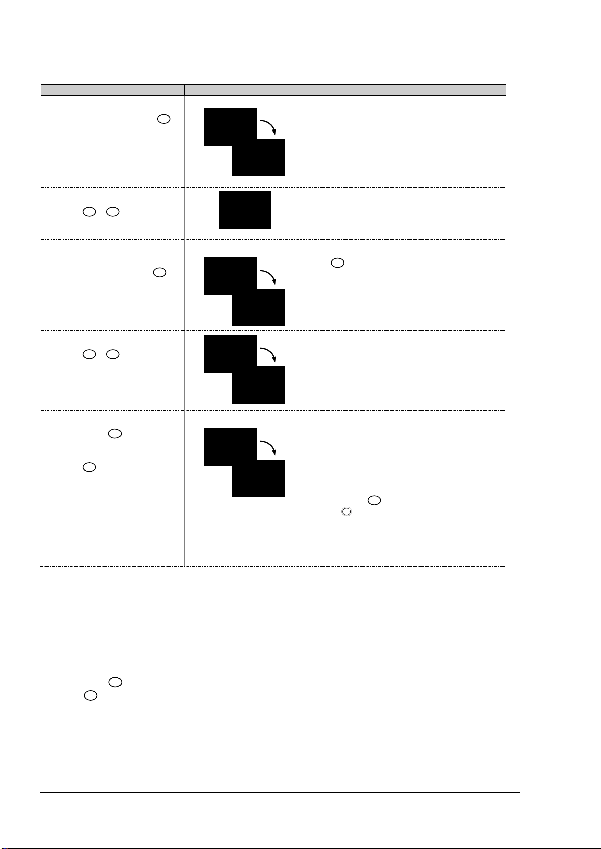
Operations Manual Series 3
6.1.3 To Select Access Level 3 or Configuration Level
Lev 3
goto
0
CODE
3
code
Conf
goto
0
CODE
4
code
Conf
Conf
goto
Lev1
goto
controller will then go through its start up sequence, starting in the
Do This The Displa y You Shoul d See Additional Notes
1. F rom any display press and hold
for more than 5 seconds
2. Press
passcode for L evel 3
or
to ent er the
3. W hen the LEV3 GOTO view is shown,
as in paragraph 1 above, press
select ‘Conf’
4. Press
passcode for Configurat ion level
or
to ent er the
to
To Select Level 3
To Select Configuration level
The display will pass from the current operating level, for ex ample,
Lev 1 to Lev 3 as the button is held down.
(If no button is then pressed for about 50 seconds the display
returns to the HOME display)
The default code is 3 :
If an in correct code is entered the display revert s to ‘goto’.
The cont roller is now in t he level 3 will then revert to the HOME
display
Note:
the code for level 3
The default co de is 4:
If an in correct code is entered the display revert s to ‘goto’.
The cont roller is now in Configurat ion level will now show Conf
mus t be pressed quickly before t he controller requ ests
To Retur n to a Lower Level
5. Press and hold
seconds
6. Press
eg LEV 1
for more t han 3
to s elect the required level
A special case exists if a security code has been
configured as ‘0’. If this has been done it is not necessary to
enter a code and the controller will enter the chosen level
immediately.
When the controller is in configuration level the
ACCESS list header can be selected from any view by
holding down the
Then press
button for more than 3 seconds.
again to select ‘ACCES’
The choices are:
LEV 1 L evel 1
LEV 2 L evel 2
LEV 3 L evel 3
ConF Configuratio n
It is not necess ary to enter a code when going f rom a higher level
to a low er level.
Alternatively, press
then press
The display will t hen flash ‘ConF’ for a few seconds and the
level select ed.
Do not power down w hile Conf is flashing. If a power down does
occur an error message w ill appear – see ‘Diagnostic Alarms’
and scroll to the Acces list header,
to s elect the required level.
26
Page 27
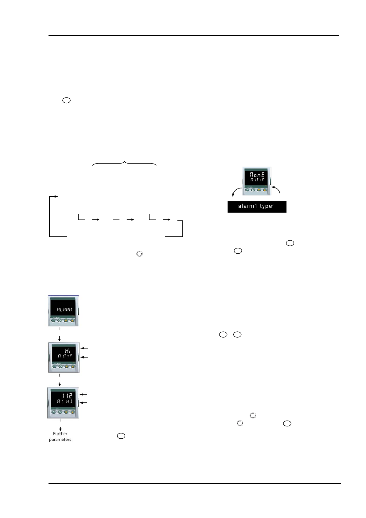
Series 3 Operations Manual
6.2 Parameter lists
Parameters are organised in lists. The top of the list shows
the list header only. The name of the list header describes
the generic function of the parameters within the list. For
example, the list header ‘ALARM’ contains parameters
which enable you to set up alarm conditions.
6.2.1 To Choose Parameter List Headers
Press
this key is pressed.
The name of the list header appears in the lower display,
followed, after a few seconds, by a scrolling longer
description of the name.
The following example shows how to select the first two list
headers.
6.2.2 To Locate a Parameter
Choose the appropriate list, then press . Each parameter
in the list is selected in turn each time this button is
pressed. The following example shows how to select the
first two parameters in the ALARM List. All parameters in
all lists follow the same procedure.
. Each list header is selected in turn every time
Scrolling parameter name
Configu ration IO- 1 LIST
PROCESS
INPUT LIST
Keep pres sing to select further lis t headers
The list is continuous
Alarm List Header
Parameter ‘Value’. In this case set to
Full Scale High Alarm
Parameter mnemonic ‘a1.typ’
followed by a scrolling message
‘alarm1 type’
Parameter ‘Value’. In this case an
’numerical’ value, set to ‘112’
Parameter mnemonic ‘a1.HI’ followed
by a scrolling message ‘alarm 1
setpoint’
Press
to jump back to the list
header
6.2.3 How Parameters are Displayed
As shown above. whenever a parameter is selected it is
displayed as a mnemonic, of four or five characters, for
example ‘A1.TYP’.
After a few seconds this display is replaced by a scrolling
banner which gives a more detailed description of the
parameter. In this example ‘A1.TYP’ = ‘alarm 1 type’. The
scrolling banner is only shown once after the parameter is
first accessed.
The name of the list header is also displayed in this way.
The upper part of the display shows the value of the
parameter.
The lower part shows its mnemonic followed by the
scrolling name of the parameter
6.2.4 To Change a Parameter Value
With the parameter selected, press
value, press
to decrease the value. If either key is held
down the analogue value changes at an increasing rate.
The new value is entered after the key is released and is
indicated by the display blinking. The exception to this is
output ‘Power’ when in manual. In this case the value is
entered continuously.
The upper display shows the parameter value the lower
display shows the parameter name.
to increase the
6.2.5 To Return to the HOME Display
Press
On release of the keys the display returns to the HOME list.
The current operating level remains unchanged.
+
.
6.2.6 Time Out
A time out applies to the ‘Go To’ and ‘Control Mode’
parameters. If no key presses are detected within a period
of 5 seconds the display will revert back to the HOME list.
Press and hold to scroll parameters forward through
the list. With depressed, press
backward.
to scroll parameters
27
Page 28
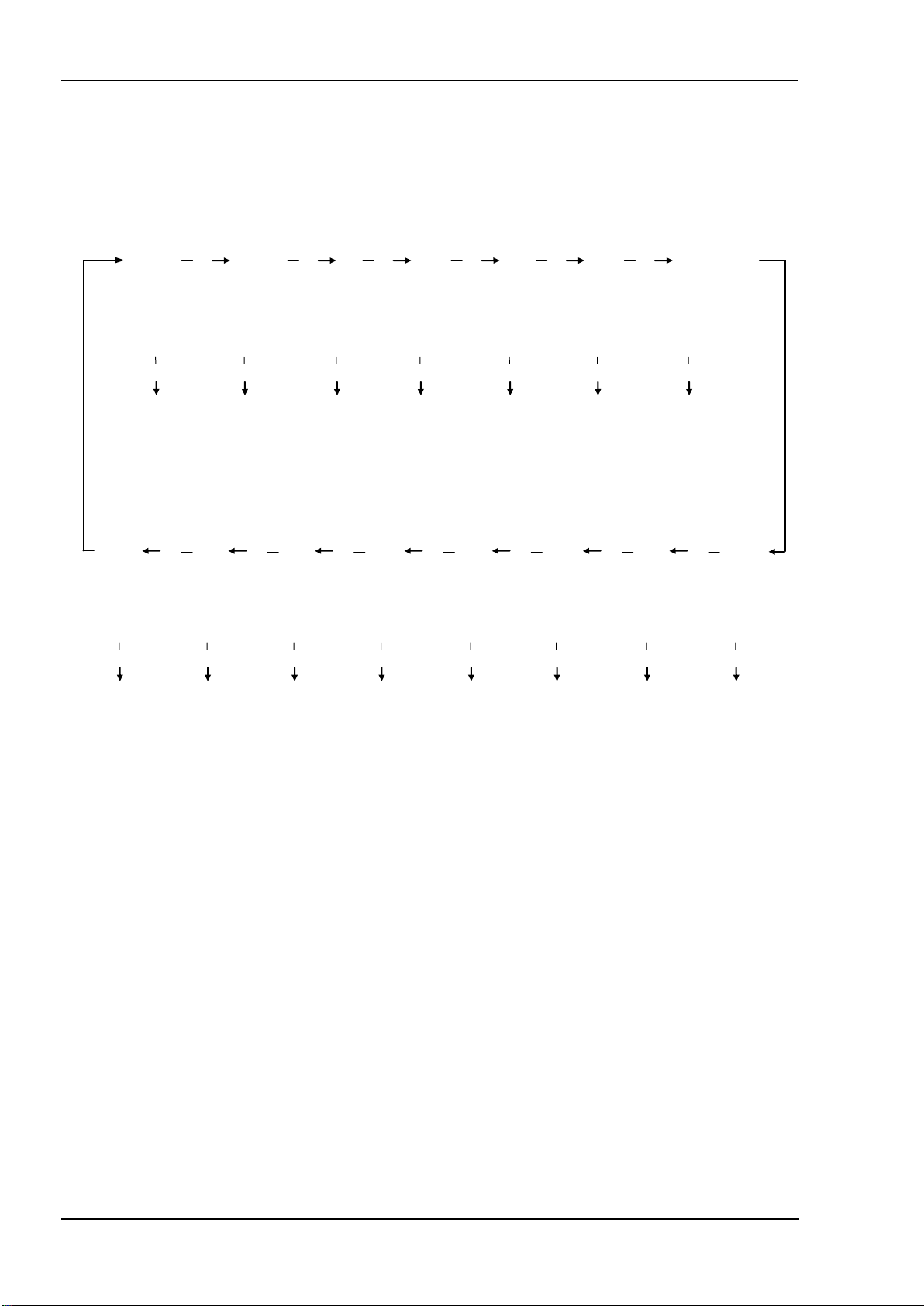
Operations Manual Series 3
6.3 Navigation Diagram
The diagram below shows the all list headings available in configuration level for Series 3 controllers.
The parameters in a list are shown in tables in the following sections of this manual together with explanations of their meanings
and possible use.
Paramet ers see
For Series 3 controllers additional lists are available, for example Output 3 and Digital Input B
Configu ration
Level 2
Paramet ers
Section 5.3
Access
Paramet ers see
Section 6.4
PROCESS
INPUT
Calibration
Section 16
LIST
Sensor Input
Paramet ers see
Section 8
Commu nications
Paramet ers see
IO1 LIST Output 2 List AA Relay List Logic Input a
Output 1 or
Input 1
Paramet ers see
Section 9
Paramet ers see
Section 15
Paramet ers see
Recipe
Section 14
Output 2
Section 9
AA Relay
(Output 4)
Paramet ers see
Section 9
Timer
Paramet ers see
Section 13
Digital Input
Paramet ers see
Section 9
Alarm
Paramet ers see
Section 12
List
Cont rol List Recipe List Comms List Timer List Alarms List Setpoint List Calibration List Access List
Control
Paramet ers see
Section 11
current
transformer List
CT Input
Paramet ers
Not Supported
Setpoint
Paramet ers see
Section 10
28
Page 29

Series 3 Operations Manual
!
Std
OP
Tr
ELAP
AL
Ct
CLr
tmr
none
ALL
Edit
Mod
Man
No
Abs.a
OFF
HEAT
Op
C.OP
err
amps
LCur
6.4 Access Parameters
The following table summarizes the parameters available under the ACCESS list header
The Access List can be selected at any time when in configuration level by holding
press
ACCESS LIST
Name Scrolling Display Parameter Des cription Values Allowed Default Acces s Level
GOTO
LEV2.P
LEV3.P
CONF.P
ID
HOME
K.LOC
COLD
stby.t
meter
or
with
SELECT A CCESS
LEVEL
LEVEL 2 PASSCODE The Level 2 passcode
LEVEL 3 PASSCODE The Level 3 passcode
CONFIG P ASSCODE T o set a Configu ration level pass code
CUSTOMER I D To set t he identification of the controller
HOM E DISPLAY See
Note 1
KEYBOARD LOCK To limit operation of the front panel buttons
COLD START
ENABLE/ D ISABLE
STANDBY TYPE Turn ALL outputs off when the controller is
METER
CONFIG URATION
See Note 4
still held down.
‘ ACCS’
Allows you to change the access level of t he
controller. P asswords prevent unauthorised
change
To configure t he parameter t o be displayed
in the low er line of the HOM E display
when in operator levels.
If ALL has been selected, t hen to
restore access to the keyboard, pow er up
the controller with the
down and ent er the configuration level
passcode. This will t ake you to the Quick
Code mode. Pres s
YES. The front panel buttons can then be
operated as normal.
Use this parameter with care.
When s et to yes t he controller will return to
factory settings on the next power up
in standby m ode. Typical use when event
alarms are used to int erlock a process.
To configure t he analogue met er to indicate
any one of the p arameters listed.
to EXIT an d select
button held
Lev.1
Lev.2
Lev.3
Conf
0-9999
0 = no pas scode will be request ed
0-9999
t.sp
no.PV
Stby
Stby
tmr
YES
Off
COOL
w.sp
pV
Operator level 1
Operator level 2
Operator level 3
Configuration lev el
Setpoin t
Output demand
Time remaining
Time elapsed
Alarm 1 setpoint
Current t ransformer
No parameter
Time remaining
Target setpoint
PV is not displayed
PV is not displayed when t he
controller is in standby m ode
Unlocked
All buttons locked
Edit keys locked See Note 2
Mode keys locked See Note 3
Manual mode locked
Press
between norm al operation and
standby mode
FEATURE UNAVAILABLE
Disable
Enable
Absolute alarms to remain activ e
All alarms off in standby
Meter dis play disabled
Heat Output demand
Cool output demand
Working s etpoint
Process value
Heat output demand
Cool output demand
Error (SP – PV)
Output current
Load current from CT
and
key down for 3 seconds, then
Lev.1
2
3
4
Conf
Std
none
to toggle
No
abs.a
Conf
Conf
Conf
Conf
Conf
Conf
Conf
Conf
Conf
Note 1
Home Display Configuration
The upper display always shows PV, the lower display is
configurable.
Std In automatic control the lower display shows setpoint.
In manual mode output power is shown.
OP Output power is shown in both automatic and manual
modes.
Ct CT current
CLr Blank display
no.pv The upper display is blank
Stby The upper display blanks when the controller is in
standby mode.
Note 2
Edit keys locked. Parameters cannot be changed but
viewed only.
AL1 First configured alarm setpoint
29
Page 30

Operations Manual Series 3
Note 3
Mode key locked. Auto/Manual cannot be operated from
the Mode key.
The following sections in this handbook describe the
parameters associated with each subject. The general
format of these sections is a description of the subject,
followed by the table of all parameters to be found in the
list, followed by an example of how to configure or set up
parameters.
Note 4
Meter Configuration
HEAT The meter shows a representation of the heat
output being applied by the control loop to the load. It is
scaled between 0 and 100% full scale deflection.
Op The meter displays the current Control Output setting
scaled between the low and high output power limits.
COOL The meter shows a representation of the cool
output being applied by the control loop to the load. It is
scaled between 0 and 100% full scale deflection.
C.OP The meter displays the current output power setting
scaled between -100 and 100%, so that a value of zero is
centred in the display. This indicates whether the controller
is currently applying heating or cooling.
w.sp The meter shows a representation of the current
working setpoint, scaled between the setpoint high and low
limits. It may be used to indicate at what point in the
setpoint range the instrument is currently operating.
PV The meter displays the current Process Variable scaled
between the range high and low values. Provides an
indication of the current temperature relative to the range
of a process.
Err The meter displays the process error (i.e. the difference
between the current temperature and the setpoint), scaled
between +10 degrees and -10 degrees. This provides a
visual indication of whether the process is close to setpoint.
Amps The meter shows a representation of the
instantaneous current through a load monitored using a
current transformer, scaled between 0 Amps and the
configured range of the Current Transformer. It may be
used to visually indicate the health of the heating elements,
since in normal use it will tend to flick from a low reading
when the heating is off, to a higher reading when the
heating is on. If the needle does not return to a low value,
the SSR may be conducting regardless of the logic signal
driving it. If the needle does not reach the expected level it
is likely that one or more of the heater elements has burned
out.
Lcur The meter displays a representation of the On State
Current in a load monitored by the current transformer
option. In normal operation it will tend to remain static and
provides an alternative means of monitoring the health of a
heating element to the 'Amps' option.
.
30
Page 31

Series 3 Operations Manual
7. Controller Block Diagram
The block diagram shows the simple building blocks which make up the controller. Each block has a list of parameters headed by
a list name. For example the ‘Input List’ contains parameters which define the input type.
The quick start code automatically sets the parameters to match the hardware.
Sensor
eg therm ocouple
Inputs Control
Sensor Input
Input List
(sect ion 8)
Setpoin t
SP List
(sect ion 10)
Digital I nput A
LA List
(sect ion 9)
Processes
Control
CTRL List
PID/on-off/Tune/Aut oMan
(section 11)
Alarm(s)
ALARM List
(section 12)
Digital I nput B
LB List
(sect ion 9)
Current
Transformer
Input
CT List
Not Supported
Timer
TI MER List
(section 13)
CT Alarm setting
CT List
Not Supported
Digital
Commu nications
COMMS List
(sect ion 15)
The Temperature (or Process Value, PV) is measured by the
sensor and compared with a Setpoint (SP) set by the user.
The purpose of the control block is to reduce the difference
between SP and PV (the error signal) to zero by providing a
compensating output to the plant via the output driver
blocks.
The timer blocks may be made to operate on a number of
parameters within the controller, and digital
communications provides an interface to data collection
and control.
The way in which each block performs is defined by its
internal parameters. Some of these parameters are
available to the user so that they can be adjusted to suit the
characteristics of the process which is to be controlled.
These parameters are found in lists and the name of each
list corresponds with the name of the function block shown
in the above diagram.
Outputs
Input/Output 1
Eg Heat
I O-1 List
(sect ion 9)
Output 2
Eg Cool
OP-2 List
(sect ion 9)
Output 3
Eg Cool
OP-3 List
(sect ion 9)
Output 4 (AA
Relay)
Eg Alarm
AA List
(sect ion 9)
To plant
actuato r
devices
RS485
31
Page 32

Operations Manual Series 3
8. Temperature (or Process) Input
From the low limit of the selected input type to the ‘High
Parameters in the input list configure the input to match your sensor. These parameters provide the following features:
Input Type and
linearisation
Display units and
resolution
Input filter First order filter to provide damping of the input signal. This may be necessary to prevent the
Fault detection Sensor break is indicated by an alarm message ‘Sbr’. For thermocouple it detects when the
User calibration Either by simple offset or by slope and gain. See section 8.2. for further details.
Over/Under range When the input signal exceeds the input span by more than 5% the PV will flash indicating under
8.1 Process Input Parameters
INPUT LIST
Name Scrolling Display Param eter Descript ion V alue Default Acces s Level
IN.TYP
UNITS
DEC.P
RNG.HI
RNG.LO
PV.OFS
FILT.T
CJ.typ
SB.typ
CJC.i n
Pv.i n
mv.i n
I NPUT
INPUT TYPE Selects input linearisation and range See section 8.1.1. for input types available Conf
DISPLAY UNITS D isplay units shown on t he
DISPLAY POINTS Decim al point posit ion
RANGE HIGH
LIMIT
RANGE LOW
LIMIT
PV O FFSET A simple offset applied to all input
FILTER TIME Input filter time OFF to 100.0 seconds
CJC TYPE Configuration of the CJC type
SENSOR BREAK
TYPE
CJC
TEMP ERATURE
PV INPUT VALUE
MILLIVOLT
INPUT VALUE
Thermocouple (TC) and 3-wire resistance thermometer (RTD) temperature detectors
Linear input (-10 to +80mV). 0-10V using external voltage divider. mA assumes a 2.49Ω external
shunt.
See the table in section 8.1.1. for the list of input types available
The change of display units and resolution will all the parameters related to the process variable
effects of excessive process noise on the PV input from causing poor control and indication. More
typically used with linear process inputs.
impedance is greater than pre-defined levels; for RTD when the resistance is less than 12Ω.
or over range. If the value is too high to fit the number of characters on the display ‘HHHH’ or
‘LLLL’ will flash. The same indications apply when the display is not able to show the PV, for
example, when the input is greater than 999.9
none No unit s - only for cust om linearisation
instrument
Range high lim it for thermocouple
RTD and mV inputs
Range low limit for thermocouple
RTD and mV inputs
values .
See section 8.2.
Defines the action which is applied
to the control output if the sensor
breaks ( open circuit).
See also section 8.1.2
Temperature measu red at the rear
terminal block. Us ed in the CJC
calculation
Current measured tem perature
Millivolt s measured at the rear PV
Input term inals
o
o
o
PErc %
nnnn
nnn.n
nn.nn
From the high limit of the selected input type to the
‘Low Range Limit’ param eter minus one display u nit.
Range Limit’ param eter minus one display u nit.
Generally one decimal point more than PV L3
Auto
o
0
C
o
50
C
oFF
on
Lat
Read
only
Minimu
m
display
to
maximu
m
display
range
xx.xx mV - read only Conf
o
C with one decimal point.
Celsius C
Fahrenheit F
Kelvin k
No DP
One DP
Two DP
o
Fixed at 50
No sens or break will be det ected
Open circu it sensor w ill be detected
Latchin g
C
o
C
nnnn
Conf
Conf
1.6
Automa
tic
Fixed at
o
0
on
Conf
L3 R/O
and if
T/C
Conf
L3 R/O
L3 R/O
L3
Conf
L3 R/O
L3 R/O
L3 R/O
L3
Auto
C
Conf and if
T/C
L3 R/O
Conf
L3 R/O
L3 R/O
32
Page 33

Series 3 Operations Manual
INPUT LIST
Name Scrolling Display Param eter Descript ion V alue Default Acces s Level
Rc.ft
RC.PV
I NPUT
ROC FILTER TIME T his provides a first order filt er for
the rat e of change filtering function
and can be used t o avoid nuisance
oFF to 0.1 to 999.9 minut es
Off means no f iltering applied
1.6
alarm triggers due to short duration
noise on the calculated rate of
change,
PV DERIVATIVE Prov ides a measure of the calculated
L3
rate of change of the temperat ure or
measu rement input as used by the
Rate of Change Alarm functions.
Usefu l when commissioning to
determine the lev el of filtering
required on the Rate of Change
alarm.
L3
8.1.1 Input Types and Ranges
Input Type Min Range Max Range Units Min Range Max Range Uni ts
Thermocouple type J -210 1200
J.tc
Thermocouple type K -200 1372
k.tc
Thermocouple type L -200 900
L.tc
Thermocouple type R -50 1700
r.tc
Thermocouple type B 0 1820
b.tc
Thermocouple type N -200 1300
n.tc
Thermocouple type T -200 400
t.tc
Thermocouple type S -50 1768
S.tc
Pt1 00 resist ance thermometer -200 850
Rtd
mV or m A linear input -10.00 80.00
mv
Value received over digital
Cms
communications ( modbus address
203).
This value m ust be updated ev ery 5
seconds or the controller w ill show
sensor break
o
o
o
o
o
o
o
o
o
-346 C 2192
-328 C 2502
-328 C 1652
-58 C 3092
32 C 3308
-328 C 23 72
-328 C 752
-58 C 3215
-328 C 1562
o
F
o
F
o
F
o
F
o
F
o
F
o
F
o
F
o
F
33
Page 34

Operations Manual Series 3
8.1.2 Operation of Sensor Break
Sensor break type (SB.TYP) can be set to operate in three different modes:
1. Off
2. On
3. Latching
SB.TYP = Off
Type of Output Output in Sensor Brea k Alar m State
For heat + cool, OP.HI and OP.LO can be set
100%
betw een +
For heat only OP.H I and OP.L O can be set bet ween
0.0% and +100%
For cool only OP.H I and OP.LO can be s et between
-100.0% and 0%
SB.TYP = on
Type of Output Output in Sensor Brea k Alar m State
For heat + cool, OP.HI and OP.LO can be set
100%
betw een +
For heat only OP.HI an d OP.LO can be set betw een
0.0% and +100%
For cool only OP.HI and OP.LO can be set between
-100.0% and 0%
SB.TYP = Lat (Alarm latching)
Type of Output Output in Sensor Brea k Alar m State
For heat + cool, OP.HI and OP.LO can be set
100%
betw een +
For heat only OP.H I and OP.L O can be set bet ween
0.0% and +100%
For cool only OP.HI and OP.LO can be set between
-100.0% and 0%
Note: When the SAFE output value is outside the OP.LO and OP.HI limits it will be clipped into range and the controller will use
the value (i.e. adjusting OP.LO or OP.HI changes the SAFE value so that it is in range).
It could take either the lower or higher OP limit depending on its value and which limit has changed. Therefore, if SAFE = 0 and
OP.LO is changed to 10, SAFE will also be set to 10. If SAFE = 50 and OP.HI is changed to 40, SAFE will change to 40.
OP.HI (100%)
Safe value has no effect
OP.HI (100%)
Safe value has no effect
OP.HI (0%)
Safe value has no effect
‘SAFE’ value provided it is not s et outside the output
limits, otherwise it will adopt OP.HI
‘SAFE’ value provided it is not set outside the output
limits .
i.e. the same as Sbrk = on
No alarm indication w ill be displayed
ALM beacon flashes when an alarm occurs . Output
alarm relay activates. ACK has no effect.
When the sensor break condition is no longer
applicable the alarm indicat ion and outpu t cancel.
ALM beacon flashes when an alarm occurs . Output
alarm relay activates. ACK has no effect.
When the sensor break condition is no longer
applicable it is necessary to press ACK to cancel the
alarm.
34
Page 35

Series 3 Operations Manual
input
mv
Rng.lo
8.2 PV Offset
All ranges of the controller have been calibrated against
traceable reference standards. This means that if the input
type is changed it is not necessary to calibrate the controller.
There may be occasions, however, when you wish to apply
an offset to the standard calibration to take account of
known errors within the process, for example, a known
sensor error or a known error due to the positioning of the
sensor. In these instances it is not advisable to change the
reference (factory) calibration, but to apply a user defined
offset.
PV Offset applies a single offset to the temperature or
process value over the full display range of the controller and
can be adjusted in Level 3. It has the effect of moving the
curve up a down about a central point as shown in the
example below:
Display
Reading
8.2.1 Example: To Apply an Offset:
Connect the input of the controller to the source device
which you wish to calibrate to
Set the source to the desired calibration value
The controller will display the current measurement of the
value
If the display is correct, the controller is correctly calibrated
and no further action is necessary. If you wish to offset the
reading:
Do This Display Additio nal Notes
1. Select Level 3 or
Conf. Then press
to select ‘I NPUT’
2. Press to
scroll to ‘PV/OFS’
3. Press
to adjust the
offset to the reading
you require
It is also possible to apply a two point offset which adjusts
both low and high points. This is done in Level 3 using the
CAL List, and the procedure is described in the Calibration
section 15.
Fixed offset
(e.g. 2)
or
pv.ofs
2.0
Factory
calibration
Electrical Input
Scrolling display
‘process input
list’
Scrolling display ‘pv
offset’
In this case an offset of
2.0 u nits is applied
8.3 PV Input Scaling
Input scaling applies to the linear mV input range only. This
is set by configuring the INPUT TYPE parameter to mV and
has an input range of –10 to 80mV. Using an external burden
resistor of 2.49Ω, the controller can be made to accept 420mA from a current source. Scaling of the input will match
the displayed reading to the electrical input levels from the
transducer. PV input scaling can only be adjusted in
Configuration level and is not provided for direct
thermocouple or RTD inputs.
The graph below shows an example of input scaling, where it
is required to display 2.0 when the input is 4mV and 500.0
when the input is 20mV .
If the input exceeds +5% of the mV.Lo or mV.Hi settings,
sensor break will be displayed.
Display
Reading
RNG.HI
eg 500.0
eg 2.0
mv.lo
eg 4 mV
mv.hi
eg 20 m V
8.3.1 Example: To Scale a Linear Input
Select Configuration level as described in section 6.1.3.
Then:
Do This Display Addition al Notes
1. T hen press
to select ‘I NPUT’
2. Press to
scroll to ‘IN.T YP’
3. Press
to ‘mV’
4. Press to
scroll to ‘MV.HI’
5. Press
to ’20.00’
6. Press to
scroll to ‘MV.LO’
7. Press
to ‘4.00’
8. Press to
scroll to ‘RHG.HI’
9. Press
to ‘500.0’
10. Press to
scroll to ‘RNG.LO’
11. Press
to ‘2.0’
Scrolling display
or
in.typ
or
20.00
mv.hi
4.00
or
mv.lo
In operat or level the
500.0
or
or
rhg.hi
In operat or level the
rhg.lo
For mA inputs
4-20mA = 9.96-49.8mV with
2.49Ω load res istor
0-20mA = 0-49.8mV with
2.49Ω load res istor
mA inpu t will detect s ensor
break if mA < 3mA
Use a cu rrent source t o remove
shunt resistor errors
Electrical Input
‘process input
list’
Scrolling disp lay ‘input
type’
Scrolling disp lay ‘linear
input hi gh’
Scrolling disp lay ‘linear
input l ow’
controller w ill read 500.0
for a mV input of 20.00
2.0
controller w ill read 2.0 for
a mV input of 4.00
35
Page 36

Operations Manual Series 3
9. Input/Output
This section refers to:
• Digital Inputs
• Relay/Logic Outputs.
The availability of these is shown in the following table:
Name Output Input Output Function I/O Sense Beacon
(lit when
active)
I/O-1
OP-2
OP-3
OP4
(AA
Relay)
LA
LB
Digital
Comms
HD, HE, HF
Heat
Cool
Alarm
Heat
Cool
Alarm
Heat
Cool
Retransmission
(setpoint,
temperature, output)
Heat
Cool
Alarm
Normal
Normal
Normal
Inverted
Normal
Inverted
OP3 3A, 3B
Normal
Inverted
Inverted
Inverted
OP1 1A, 1B
OP2 2A, 2B
OP4 AA, AB, AC
C, LA
LB, LC
Terminal
36
Page 37

Series 3 Operations Manual
AL3
AL4
ALL.A
nw.AL
Sbr
t.End
t.run
mAn
rmt.F
Pwr.f
prg.e
9.1 Input/Output Parameters
9.1.1 Input/Output 1 List (IO-1)
May be configured as relay, logic ON/OFF. Connections are made to terminals 1A and 1B. OP1 beacon is operated from the IO-1
channel when it is configured as an output.
INPUT/OUTPUT LIST 1 ‘IO-1 ’
Name Scrolling Display Parameter Description Value Defaul t Access Level
1.id
I/O 1 TYPE I/O chan nel 1 hardware t ype
defined by the hardware
fitted
As
ordered
Read only
1.FUNC
1.SRC.A
1.SRC.B
1.SRC.C
1.SENS
I/O 1 F UNCTION I/O channel function.
If the inst rument is ordered
as valv e positioner ( codes VC
or VP) , only options available
are , none, d.out, UP, or
dwn
Note: If output 1 is set to
Up ensure the other valve
positio n output is set to
dwn and vice versa
I/O 1 SOURCE A These param eters only
I/O 1 SOURCE B
I/O 1 SOURCE C
I/O 1 SENSE To configure t he sense of t he
appear when the channel
funct ion is a Digital ou tput,
i.e. 1.FUNC = d.out
Selects an event status to be
connected to the output
channel.
The output status is the
result of an OR of Src A, Src
B, Src C, an d Src D
Up to four ev ents can,
therefore, operat e the
output
input or output channel
none
d.out
Heat
CooL
none
AL1
AL2
Ct.AL
Lbr
nor
Inv
Note 1:
A DC output may require calibration. This is described in section 15.
Disabled. If disabled no further
paramet ers are shown
Digital outpu t
Heat output
Cool output
No event connected to the output
Alarm 1
Alarm 2
Alarm 3
Alarm4
All alarms
Any new alarm
CT alarm, load, leak & ov ercurrent
Loop break alarm
Sensor break alarm
FEATURE UNAVAILABLE
FEATURE UNAVAILABLE
Manual status
Remote fail
Power fail
FEATURE UNAVAILABLE
Normal
Inverted
As
ordered
none
nor
Conf
Conf
Conf
37
Page 38

Operations Manual Series 3
9.1.2 Remote Digital Setpoint Select and
reLy
d.out
Remote Fail
These parameters were added in software version 1.11, and
subsequent versions, and are associated with the
retransmission of remote setpoint through master comms.
‘rmt’ allows the remote setpoint to be selected via a digital
input and ‘rmt.F’ is a flag which is set if no comms activity is
detected for 5 seconds or more when writing to the remote
setpoint. The flag is reset when writing to the remote
setpoint resumes.
9.1.3 Sense
If the module is an output, ‘normal’ means a relay output is
energised for 100% PID demand. For a heating or cooling
output, set this parameter to ‘nor’.
‘Inverted’ means a relay output is energised for 0% PID
demand
For an alarm output set this parameter to ‘Inv’ so that it de-
energises to the alarm state.
If the module is an input, ‘normal’ means the function is
activated when the input contact is closed, and ‘inverted’
means the function is activated when the input contact is
open.
9.1.4 Source
The four parameters SOURCE A, SOURCE B, SOURCE C,
and SOURCE D appear when the output is configured as a
digital output i.e. ‘-.FUNC’ = ‘d.Out’ and provide the facility
to connect up to four alarms or events to operate a single
output (normally configured as a relay). If any one of the
events becomes true then the output relay will operate.
SRC.A
SRC.B
SRC.C
SRC.D
OR
SEnS
Nor
Output
(relay)
Inv
9.1.6 Example: To Configure IO-1 Relay to
Operate on Alarms 1 and 2:
Do This Di splay Additio nal Notes
1. From any display,
press
times as necessary to
select ‘IO-1’
2. Press to
scroll to ‘1. ID’
as many
T his is the ident ification
Scrolling disp lay ‘io-
1 list’
of the hardware fitt ed
and cannot be adjust ed.
1.id
3. Press to
scroll to
‘1.FU NC’
4. Press
to s elect ‘d.out’
5. Press t o
scroll to ‘1.SRC.A’
6. Press
to s elect the
event which you want
to operate the output,
eg ‘AL.1’
7. If a second event
is required to operate
the same output , press
to s elect
‘1.SRC.B’
8. Press
to s elect the
second event which you
want to operate the
output, eg ‘AL.2’
The output is
1.func
or
or
or
configured as a digit al
output function.
Scrolling display ‘io
1 function’
The output will activate
if either alarm 1 or
alarm 2 occur .
Scrolling disp lay ‘io
1 source a’
Scrolling display ‘io
1 source b’
Continue to select up to
four events if required
using 1.SRC.C and
1.SRC.D
9.1.5 Power Fail
An output, configured as a digital output, can be made to
operate following a power fail. It can be acknowledged in
the same manner as an alarm but no alarm message is given.
9. Press to
scroll to ‘1.SENS’
10. Press
to s elect ‘Inv’
or
‘Inv erted’ means a relay
outp ut is energis ed for
0% PID demand
‘Normal’ means a relay
outp ut is energis ed for
100% PID demand
Scrolling display ‘io 1
sense’
38
Page 39

Series 3 Operations Manual
9.1.7 Output List 2 (OP-2)
This is an optional normally open relay and is available on terminals 2A and 2B. The way in which this output operates is
determined by parameters in the OP- 2 List. OP2 beacon is operated from this output channel.
OUTPUT LIST 2 ‘op-2’
Name Scrolling
2.id
2.FUNC
2.SRC.A
2.SRC.B
2.SRC.C
2.SRC.D
2.SENS
Display
OUTPUT 2
TYPE
FUNCTI ON Output channel 2 function
I/O 2 SOURCE A T hese parameters only appear
I/O 2 SOURCE B
I/O 2 SOURCE C
I/O 2 SOURCE D
SENSE To configure the polarity of
* The mnemonic for the alarm will change depending upon the alarm configuration.
Parameter Description Value Default Access Level
Outpu t channel 2 hardware
type
If the inst rument is ordered as
valve positioner (codes VC or
VP) , only options available are ,
none, d.out, UP, or dwn
Note: If output 2 is set to Up
ensure the other valve
positio n output is set to dwn
and vice ver sa
when the channel function is a
Digital O P,
i.e. 2.FUNC = d.Out
Selects an event status to be
connected to the output
channel.
The output status is the result
of an OR of Src A, Src B, Src C,
and Src D
Up to four ev ents can,
therefore, operat e the outpu t
output channel 2
reLy
none
d.out
Heat
CooL
none
AL1
AL2
AL3
AL4
ALL.A
nw.AL
Ct.AL
Lbr
Sbr
mAn
rmt.F
Pwr.f
prg.e
nor
Relay output
Disabled. If disabled no further parameters are
shown
Digital outpu t
Heat output
Cool output
No event connected to the output
Alarm 1 *
Alarm 2 *
Alarm 3 *
Alarm4 *
All alarms
Any new alarm
CT alarm, load, leak & ov ercurrent
Loop break alarm
Sensor break alarm
Manual status
Remote fail
Power fail
FEATURE UNAVAILABLE
Normal
As
ordered
As
ordered
none
nor
Read only
Conf
Conf
Conf
9.1.8 Output List 3 (OP-3)
This is a normally 4-20 or 0-20mA isolated dc output. The way in which this output operates is determined by parameters in the
OP- 3 List. OP3 beacon is operated from this output channel.
OUTPUT LIST 3 ‘op-3’
Name Scrolling
3.id
3.FUNC
3.rng
Display
OUTPUT 3
TYPE
FUNCTI ON Output channel 3 function
DC OUTPUT
RANGE
Note 1: A DC output may require calibration.
Parameter Description Value De fault Access Level
Outpu t channel 3 hardware
type
If the inst rument is ordered as
valve positioner (codes VC or
VP) , only options available are ,
none, d.out, UP, or dwn
Note: If output 3 is set to Up
ensure the other valve
positio n output is set to dwn
and vice ver sa
DC out put calibration.
Only shown if
3.id= dC.Op
nonE
dC.Op
none
Heat
CooL
w.sp
pV
Op
Inv
4.20
0.20
Output not fitted As ordered Read only
0-20mA out put See note 1
Disabled. If disabled no further
paramet ers are shown
Heat output
Cool output
Working s etpoint re-transmission
Process variable re-transmission
Output re-transmission
Inverted
4-20mA
0-20mA
d.out
Shown if I/O 3 TYPE = dc.OP
Retransmission
4.20
Conf
Conf
39
Page 40

Operations Manual Series 3
9.1.9 AA Relay (AA) (Output 4)
This is a changeover relay. Connections are made to terminals AA, AB, and AC. The way in which this relay operates is
determined by parameters in the AA List. OP4 beacon is operated from the AA relay output channel.
AA RELAY ‘aa’
Name Scrolling
4.TYPE
4.FUNC
4.SRC.A
4.SRC.B
4.SRC.C
4.SRC.D
4.SENS
Display
OUTPUT 4
TYPE
FUNCTI ON Output channel 4 function
I/O 4 SOURCE A T hese parameters only appear
I/O 4 SOURCE B
I/O 4 SOURCE C
I/O 4 SOURCE D
SENSE To configure the polarity of
* The mnemonic for the alarm will change depending upon the alarm configuration.
Parameter Description Value De fault Access Level
Outpu t channel 4 hardware
type
If the inst rument is ordered as
Valve Position (codes VC or
VP) , only values none, d.out,
UP, or dwn are available
Note: If output 4 is set to up
ensure the other valve
positio n output is set to dwn
and vice ver sa
when the channel function is a
Digital O P,
i.e. 4.FUNC = d.Out
Selects an event status to be
connected to the output
channel.
The output status is the result
of an OR of Src A, Src B, Src C,
and Src D
Up to four ev ents can,
therefore, operat e the outpu t
output channel 4
reLy
none
d.OUt
Heat
CooL
none
AL1
AL2
AL3
AL4
ALL.A
nw.AL
Ct.AL
Lbr
Sbr
mAn
rmt.F
Pwr.f
prg.e
nor
Inv
Relay output
Disabled
Digital outpu t
Heat output
Cool output
No event connected to the output
Alarm 1 *
Alarm 2 *
Alarm 3 *
Alarm4 *
All alarms
Any new alarm
CT alarm, load, leak & ov ercurrent
Loop break alarm
Sensor break alarm
Manual status
Remote fail
Power fail
FEATURE UNAVAILABLE
Normal
Inverted
reLy
d.OUt
none
nor
Read only
Conf
Conf
Conf
40
Page 41

Series 3 Operations Manual
9.1.10 Digital Input Parameters
Digital Input A. This is an optional input wired to terminals C and LA. The input is typically from a voltage free contact, which
can be configured to operate a number of functions as determined by parameters in the LA List.
Note: Terminal C is common to the CT input and is, therefore, not isolated from the CT.
Digital Input B. This is wired to terminals LB and LC.
The parameter lists for LB are identical as shown below:
LOGIC INPUT LIST ‘la’ / ‘LB’
Name Scrolling Dis play Parameter Description Val ue Default Access Level
L.TYPE
L.d.in
L.SENS
LOGIC INPUT
TYPE
LOGIC INPUT
FUNCTI ON
LOGIC INPUT
SENSE
Input channel type
To configure the function of the
digital input
To configure the polarity of the
input channel
L.IP
none
Ac.AL
SP2
Loc.b
Man
Sby
rmt
UP
dwn
nor
Inv
Logic inpu t Conf
Read only
Input not used
Alarm ackn owledge
Setpoint 2 s elect
Front keypad disable
Manual status
Standby mode. In this mode control
outputs go to zero demand
To allow a remote setpoint to be
selected t hrough the LA digital input.
Remote key ‘Up’
Remote key ‘Down’
Normal
Inverted
Ac.AL
nor
Conf
Conf
41
Page 42

Operations Manual Series 3
9.2 Current Transformer Input Parameters (Current Transformer is not available)
This is not available on Series 3 controllers.
Measures, via an external current transformer, the current flowing through the electrical load when the heat output is ‘on’ (load
current) and also when it is ‘off’ (leakage current).
Alarm If the load current is lower than a threshold limit or the leakage current is higher than a threshold limit,
then an alarm triggers. The hysteresis to exit from either of these alarm conditions is fixed at 2% of the
current transformer span.
Full scale value Selectable from 10 to 1000A
CURRENT TRANSFORMER LIST ‘CT- iNP’
Name Scrolling Display Parameter Description Value Defa ult Access Level
Ct.Id
CT.SRC
CT.RNG
CT.LAT
Ld.alm
LK.ALM
Hc.alm
LD.AMP
LK.AMP
CT.MTR
MODULE TYPE CT m odule identity
CT SOURCE Selects the output controlling the
CT RANGE Set s the CT inputs range
CT ALARM
LATCH TYPE
LOAD CURRENT
THR ESHOL D
LEAK CURRENT
THR ESHOL D
OVER
CURRENT
THR ESHOL D
LOAD CURRENT Meas ured load current L3 if CT input
LEAK CURRENT CT input leakage current L 3 if CT input
CT METER RANGE To set the range of the meter. 0 to 1000 L3
current measured by t he CT input .
The source can only be s elected if
the ou tput has been conf igured for
Heat or Cool
To configure t he latch mode of the
CT inpu t alarm.
A descript ion of alarm latchin g is
given in t he alarm section
Load open circuit alarm threshold –
low alarm
Leakage cu rrent in the off state
alarm threshold – high alarm
Overcurrent threshold – high alarm
Ct.In
none
IO-1
OP-2
aa
0 to CT full scale value (1000)
nonE
Auto
man
Off to CT fu ll scale value (set table to
3000)
Off to CT fu ll scale value (set table to
3000)
Off to CT fu ll scale value (set table to
3000)
CT inpu t circuit fitt ed Conf read only
None
Input/output 1
Output 2
AA Relay
No latching
Latch ed with automatic
reset
Latched wit h manual reset
Conf
no
Read only
Read only
Conf if CT alarm
enabled
enabled
enabled
42
Page 43

Series 3 Operations Manual
Limits the rate of change of the setpoint.
10. Setpoint Generator
The setpoint generator provides the target value at which it
is required to control the process. It is shown in the
controller block diagram. The following functions are
available:
Number of
setpoints
Two - setpoint 1 (SP1) and setpoint 2 (SP2).
Each may be selected by a dedicated
parameter or externally switched via a digital
input suitably configured.
An application example might be to use SP1
Setpoint
limits
Set point
rate limit
Direct
setpoint
access
High and low limits can be pre-set to prevent
inadvertent adjustment of the setpoint
beyond that allowable for the process
Allows the setpoint to change from its
current level to a new level at a fixed rate.
The selected setpoint is accessible directly
from the HOME display by pressing the raise
or lower buttons
for normal operation and SP2 to maintain a
low overnight temperature.
10.1 Setpoint Parameters
SETPOINT LIST ‘SP’
Name Scrolling Display Parameter Description Val ue Defaul t Access Level
SP.SEL
SP1
SP2
SP.HI
SP.LO
rEm.sp
l - r
SP.RAT
rampu
loc.t
REM.HI
REM.lo
Rop.hi
Rop.lo
SETPO INT
SELECT
SETPO INT 1 Main or normally selected s etpoint Low t o high setpoint limits
SETPO INT 2 Secondary or standby setpoint Low to high setpoint limits
SETPO INT HIG H
LIMIT
SETPOINT LOW
LIMIT
REMOT E
SETPO INT
REMOT E
SETPO INT
SELECT
SETPO INT RATE
LIMIT
SETPO INT RAMP
UNITS
LOCAL SETPOINT
TRIM
REMOT E INPUT
HIGH SCALAR
REMOT E INPUT
LOW SCALAR
SETPO INT
RETRANS HIG H
SETPO INT
RETRANS LOW
This enables t he main or seco ndary
setpoint t o be selected form th e front
panel buttons
Maxim um allowable set point sett ing Setpoin t low limit ( SP.LO ) to high range lim it.
Minimu m allowable setpoint s etting L ow range limit t o Setpoint high limit ( SP.HI ).
Reads t he current remote set point value
when rem ote setpoint is in use
To select the remot e digital
commu nications set point
Operat es on both SP 1 and SP2
To set the units for the setpoint rate limit
Local trim on remote set point. Applies a
fixed offset to the remote set point
Sets t he maximum s cale limit for the
remote setpoint
Sets t he minimum scale limit for the
remote setpoint
Sets the upper limit for the setpoint
retransmission
Sets the lower limit for the setpoint
retransmission
SP1
SP2
Also limited by t he rng.hi and rng.lo
paramet ers
Also limited by t he rng.hi and rng.lo
paramet ers
Read only
No
YES
Step chan ge (OFF) or 0.1 to 3000 dis play
units per minute.
Resolution one decimal place more than P V
min
Hour
SEC
-199.9 to 300.0
Between Setpoint High and Low Limits up to
firmware v ersion 2.11.
From 2.11 the values can be v aried within t he
entire ins trument rang e. This allows, for
example, a 0-5V device to be us ed with a 010V input such that the 5V can correspond to
the fu ll setpoint range.
These two paramet ers have been added from
firmware v ersion 2.11.
They replace Set point High and Low Limits as
the outer limits for a retransmitted setpoint.
In versions prior to 2.11 the transmitted
setpoint is scaled against it s full range.
Setpoint Retrans High & Low allow t he
retransmitted setpoint to be scaled against a
sub-range. The values correspond t o the
setpoint transmitted at 4 and 20mA – if the
setpoint is outs ide this range then it is clipped.
Setpoint 1 selected
Setpoint 2 s elected
Not s elected
Selected
Minutes
Hours
Seconds
SP1
0
0
Range
High
Limit
Range
Low
Limit
no
Off
min
0.0
L3
L3
L3
L3
L3
L3
L3
L3
Conf
L3
L3
L3
43
Page 44
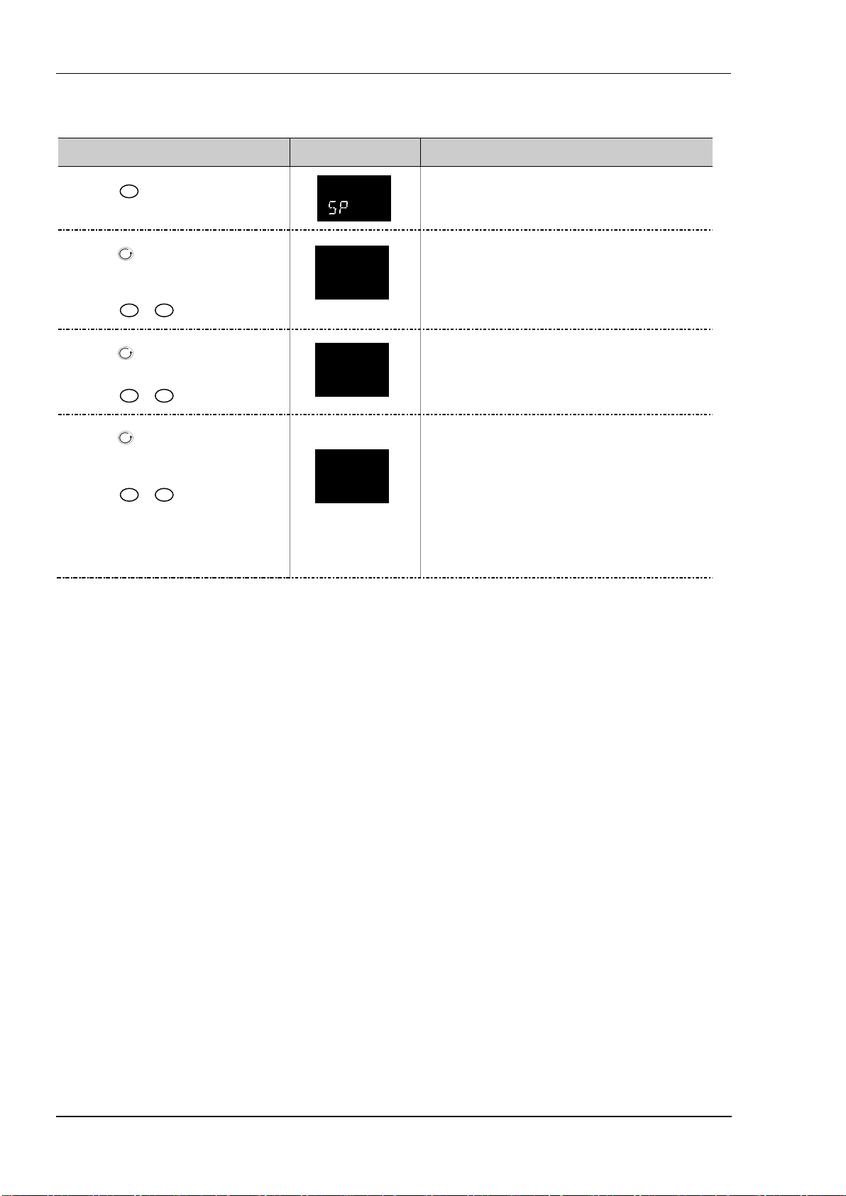
Operations Manual Series 3
10.2 Example: To Set Ramp Rate
6.000
This is available in Level 3.
1. Press
Do This The Display You Should
as many times as necessary to
select ‘SETPOINT LIST’
See
Additional Notes
2. Press as many times as necessary to
scroll to ‘SP1’
3. Press
or
to adjust setpoint 1
4. Press to scroll to ‘SP2’
5. Press
or
to adjust setpoint 2
6. Press as many times as necessary to
scroll to ‘SP.RAT’
7. Press
or
to set the rate at
which you require the setpoint to change
This step can be repeated for the lower setpoint limit
73.00
sp1
‘SP.LO’
50.00
sp2
Whenever the setpoint is changed, the controller will ramp
Sp.rat
from its current setpoint to the new value at the rate set in
units per second, minute or hours as set by the ‘RAMPU’
parameter.
It will also change at the same rate when switching
between SP2 and SP1 (but not between SP1 and SP2)
The setpoint rate resolution is g enerally one decimal p oint
more than setpoint/PV resolution
44
Page 45

Series 3 Operations Manual
Measu red
11. Control
Parameters in this section allow the control loop to be set up for optimum control conditions. An example of a temperature
control loop is shown below:
Control Output
Power
Regulat or
Heater
Setpoin t
Control
Meth od
Error
PV
Control
Loop
temperature
11.1 Types of Control
Three types of control loop may be configured. These are On/Off control or PID control.
11.1.1 On/Off Control
On/Off control is the simplest means of control and simply turns heating power on when the PV is below setpoint and off when it
is above setpoint. As a consequence, On/Off control leads to oscillation of the process variable. This oscillation can affect the
quality of the final product and may be used on non-critical processes. A degree of hysteresis must be set in On/Off control if the
operation of the switching device is to be reduced and relay chatter is to be avoided.
If cooling is used, cooling power is turned on when the PV is above setpoint and off when it is below.
It is suitable for controlling switching devices such as relays, contactors, triacs or digital (logic) devices.
The actual temperature measured at the process (PV) is connected to
the input of the controller. This is compared with a setpoint (or
required) temperature (SP). If there is an error between the set and
measured temperature the controller calculates an output value to call
for heating or cooling. The calculation depends on the process being
controlled but normally uses a PID algorithm. The output(s) from the
controller are connected to devices on the plant which cause the
heating (or cooling) demand to be adjusted which in turn is detected by
the temperature sensor. This is referred to as the control loop or closed
loop control.
11.1.2 PID Control
PID, also referred to as ‘Three Term Control’, is an algorithm which continuously adjusts the output, according to a set of rules, to
compensate for changes in the process variable. It provides more stable control but the parameters need to be set up to match
the characteristics of the process under control.
The three terms are:
Proportional band PB
Integral time TI
Derivative time TD
The output from the controller is the sum of the contributions from these three terms. The combined output is a function of the
magnitude and duration of the error signal, and the rate of change of the process value.
It is possible to turn off integral and derivative terms and control on proportional only (P), proportional plus integral (PI) or
proportional plus derivative (PD).
PI control might be used, for example, when the sensor measuring an oven temperature is susceptible to noise or other electrical
interference where derivative action could cause the heater power to fluctuate wildly.
PD control may be used, for example, on servo mechanisms.
In addition to the three terms described above, there are other parameters which determine how well the control loop performs.
These include Cutback terms, Relative Cool Gain,and Manual Reset and are described in detail in subsequent sections.
45
Page 46

Operations Manual Series 3
11.2 Control Parameters
The control loop is configured by the parameters listed in the following table:
CONTROL LIST
Parameter
Name
CTRL.H
CTRL.C
CTRL.A
PB.UNT
ATUNE
AT.R2G
PB
TI
TD
R2G
CBHi
CBLo
MR
LBT
OP.HI
‘CTRL’
Parameter Description
Value Default Access
(Scrolling Display)
HEATING TYPE
Selects the chan nel 1 control algorithm.
Different algorithms may be selected
for channels 1 and 2. In temperature
control applications, Ch1 is usually t he
Pid PID Conf
off Heating off
on.of On/Off
MTr Valve position control (n/a)
heating channel, Ch2 is the cooling
channel.
COOLING TYPE
Selects the channel 2 Control
algorithm. Different algorithms may be
selected for channels 1 and 2.
oFF Cooling disable Conf
pid PID
on.of On/Off
This is not available if t he instrument is
a valve posit ion controller
CONTROL ACTION
Selects the direction of the control. i.e
reverse or direct acting.
rev Reverse acting. Output decreases as
PV increases
dir Direct acting. Output increases as PV
decreases
PROPORTIONAL BAND UNITS enG In engineering units
Perc In percent
AUTO-TUNE ENABLE OFF Auto-tune off OFF L3
On Set to ‘on’ to start auto-tuning
FaiL Displayed if Autotune cannot be
completed
AUTOTUNE CONFIGURES R2G YES R2G will be set by Auto-tune yes Conf
No Allows a value for R2G to be entered
manually
PROPORTIONAL BAND 0.1 to 9999 display units or
1 to 999.9% if proportional band expressed as %
INTEGRAL TIME
Off to 9999 seconds 360 sec L3
DERIVATIVE TIME
RELATIVE C OOL GAIN
Off to 9999 seconds
TD defaults to OFF for valve position control
0.1 to 10.0 1.0 L3
CUTBACK HIGH
Auto or 1t o 3000 display units Auto =
CUTBACK LOW
Auto or 1 to 3000 display units Auto =
MANUAL RESET 0.0 to 1 00.0% (heat only)
-100.0 to 100.0% ( heat/cool)
LOOP BREAK TIME
The loop break alarm attempts to
detect loss of restoring action in the
Off Setting loop Break Time to OFF
disables the Loop Break Alarm
1 to 9999 minutes
control loop by checking the control
output, the process value and its rate of
change.
Loop break detection works for all
control algorithms: PID, VP and ONOFF.
Note: This is not to be confused with
load failure and partial load failure.
OUTPUT HIGH
Adjust to limit the maximum heating
+100.0%
power applied to the process
Level
rev Conf
20 L3
60 sec
L3
L3
3xPb
L3
3XPb
0.0% L3
OFF L3
100.0% L3
46
Page 47

Series 3 Operations Manual
CONTROL LIST
Parameter
Name
OP.LO
D.BAND
‘CTRL’
Parameter Description
(Scrolling Display)
OUTPUT LOW
Adjust to limit the maximum cooling
power applied to the process or to
apply a minimum heating power
CHANNEL 2 DEAD BAND
Period when no output is demanded
Value Default Access
Level
+100.0%
0.0 (he at
only)
L3
-100
(cool)
Off or 0.1 to 100.0% of the cooling proportional
OFF L3
band
from either channel 1 or channel 2
Adjust, for example, to increase the
period when no heating o r cooling
power is applied
HYST.H
HYST.C
SAFE
HEATING HYSTERESIS 1 to 9999 display units 1 L3 On/off
COOLING HYSTERESIS 1
SAFE OUTPUT POWER
-100.0 to 100.0% limited b y OP.HI an d OP.LO 0.0% L3
only
To set the output level in a sensor break
(open circuit) condition
F.MOD
FORCED MANUAL OUTPUT MODE
Selects how the loop behaves on
transfer from Auto to Manua l.
Transfer from Manual to Auto is always
bumpless.
none Transfer between Auto /Manual/Auto is
bumpless
SteP Transfer from Aut o to Manual, t he
output goes to a pre-set value (F.OP)
Last Transfe r from Auto to Manual, t he
none L3
output goes to the previously set
manual value
Cool.t
F.OP
NON-LINEAR COOLING TYPE
This selects an algorithm most suited to
the type of cooling. Ty pically used in
extruders.
FORCED OUTPUT
Lin Linear Conf
OIL Oil coolin g
H20 Water cooling
Fan Forced air cooling
-100.0 to 100.0% limited by OP.HI and OP.LO 0.0 L3
To pre-set a value for th e Manual output
when F.MOD = STEP
A- M
LOOP MODE – AUTO MANUAL OFF
Auto To select automatic operation L3
Man To select man ual operation
OFF Con trol outputs inhibited
lbr
TU.HI
TU.LO
LOOP BREAK STATUS No Shows the current status of loop break. Read
only
TUNE HIGH LIMIT. Set this to limit the
maximum h eating outp ut during
autotune
YES
Range between OP .HI and OP.LO
+
100.0
L3
TUNE LOW LIMIT. Set this to limit the
maximum c ooling output during
autotune
Parameters are further described in the following sections.
47
Page 48

Operations Manual Series 3
11.2.1 Proportional Band ‘PB’
The proportional band, or gain, delivers an output which is proportional to the size of the error signal. It is the range over which
the output power is continuously adjustable in a linear fashion from 0% to 100% (for a heat only controller). Below the
proportional band the output is full on (100%), above the proportional band the output is full off (0%) as shown in the diagram
below.
The width of the proportional band determines the magnitude of the response to the error. If it too narrow (high gain) the system
oscillates by being over responsive. If it is too wide (low gain) the control is sluggish. The ideal situation is when the proportional
band is as narrow as possible without causing oscillation.
The diagram also shows the effect of narrowing proportional band to the point of oscillation. A wide proportional band results in
straight line control but with an appreciable initial error between setpoint and actual temperature. As the band is narrowed the
temperature gets closer to setpoint until finally becoming unstable.
The proportional band may be set in engineering units or as a percentage of the controller range.
Output
100%
50%
0%
Proportional band
wide
narrow
Setpoin t
Temp erature
Temp erature
Setpoin t
Increasingly narrower
proportional band
Time
11.2.2 Integral Term ‘TI’
In a proportional only controller, an error between setpoint and PV must exist for the controller to deliver power. Integral is used
to achieve zero steady state control error.
The integral term slowly shifts the output level as a result of an error between setpoint and measured value. If the measured
value is below setpoint the integral action gradually increases the output in an attempt to correct the error. If it is above setpoint
integral action gradually decreases the output or increases the cooling power to correct the error.
The diagram below shows the result of introducing integral action.
The units for the integral term are measured in time (1 to 9999 seconds in Series 3 controllers). The longer the integral time
constant, the more slowly the output is shifted and results in a sluggish response. Too small an integral time will cause the
process to overshoot and even oscillate. The integral action may be disabled by setting its value to Off.
Temp erature
Setpoin t
Proportional
only control
Proport ional + Integral
control
Time
48
Page 49

Series 3 Operations Manual
Temp erature
Time
Temp erature
11.2.3 Derivative Term ‘TD’
Derivative action, or rate, provides a sudden shift in output as a result of a rapid change in error. If the measured value falls
quickly, derivative provides a large change in output in an attempt to correct the perturbation before it goes too far. It is most
beneficial in recovering from small perturbations.
SP
SP
Proportional + Integral response
Response with deriv ative action
included
Time
The derivative modifies the output to reduce the rate of change of error. It reacts to changes in the PV by changing the output to
remove the transient. Increasing the derivative time will reduce the settling time of the loop after a transient change.
Derivative is often mistakenly associated with overshoot inhibition rather than transient response. In fact, derivative should not
be used to curb overshoot on start up since this will inevitably degrade the steady state performance of the system. Overshoot
inhibition is best left to the approach control parameters, High and Low Cutback.
Derivative is generally used to increase the stability of the loop, however, there are situations where derivative may be the cause
of instability. For example, if the PV is noisy, then derivative can amplify that noise and cause excessive output changes. In these
situations it is often better to disable the derivative and re-tune the loop.
If set to Off(0), no derivative action will be applied.
In Series 3 controllers, derivative is calculated on change of PV. For applications such as furnace temperature control, it is
common practice to use Derivative on PV to prevent thermal shock caused by a sudden change of output as a result of a change in
setpoint.
11.2.4 Relative Cool Gain ‘R2G’
The proportional band parameter ‘PB’ adjusts the proportional band for the heating output. Relative cool gain adjusts the cooling
proportional band relative to the heating proportional band. If the rate of heating and rate of cooling are widely different, it may
be necessary to manually adjust Relative Cool Gain to achieve the optimum settings for the cooling proportional band. A nominal
setting of around 4 is often used.
Note, this parameter is set automatically when Auto-tune is used unless the parameter ‘AT.R2G’ is set to ‘No’.
49
Page 50

Operations Manual Series 3
11.2.5 High and Low Cutback
Cutback high ‘CBHI’ and Cutback low ‘CBLO’ are values that modify the amount of overshoot, or undershoot, that occurs during
large step changes in PV (for example, under start-up conditions). They are independent of the PID terms which means that the
PID terms can be set for optimal steady state response and the cutback parameters used to modify any overshoot which may be
present.
Cutback involves moving the proportional band towards the cutback point nearest the measured value whenever the latter is
outside the proportional band and the power is saturated (at 0 or 100% for a heat only controller). The proportional band moves
downscale to the lower cutback point and waits for the measured value to enter it. It then escorts the measured value with full
PID control to the setpoint. In some cases it can cause a ‘dip’ in the measured value as it approaches setpoint, as shown in the
diagram below, but generally decreases the time needed to bring the process into operation.
The action described above is reversed for falling temperature.
If cutback is set to Auto the cutback values are automatically configured to 3*PB.
Temp erature
Setpoin t
Upper cutback point, CBH
0% out put level
100 % output level
Lower cut back point, CBL
Time
11.2.6 Manual Reset
In a full three-term controller (that is, a PID controller), the integral term automatically removes the steady state error from the
setpoint. If the controller is set as a PD controller, the integral term will be set to ‘OFF’. Under these conditions the measured
value may not settle precisely at setpoint. The Manual Reset parameter (MR) represents the value of the power output that will
be delivered when the error is zero. You must set this value manually in order to remove the steady state error.
11.2.7 Control Action
When set to reverse (REV) the output increases when the PV is below setpoint. This is the best setting for heating control.
For cooling control only set Control Action to direct (DI R).
11.2.8 Loop Break
The loop is considered to be broken if the PV does not respond to a change in the output. Since the time of response will vary
from process to process the Loop Break Time parameter allows a time to be set before a Loop Break Alarm is initiated. In these
circumstances the output power will drive to high or low limit. For a PID controller, if the PV has not moved by 0.5 x Pb in the
loop break time the loop is considered to be in break. The loop break time is set by the Auto-tune, a typical value is 12 x Td. For
an On/Off controller Loop Break Time is not shown and loop break alarm is inhibited.
11.2.9 Cooling Algorithm
The method of cooling may vary from application to application.
For example, an extruder barrel may be cooled by forced air (from a fan), or by circulating water or oil around a jacket. The
cooling effect will be different depending on the method. The cooling algorithm may be set to linear where the controller output
changes linearly with the PID demand signal, or it may be set to water, oil or fan where the output changes non-linearly against
the PID demand. The algorithm provides optimum performance for these methods of cooling.
11.3 Tuning
In tuning, you match the characteristics (PID parameters) of the controller to those of the process being controlled in order to
obtain good control. Good control means:
• Stable, ‘straight-line’ control of the PV at setpoint without fluctuation
• No overshoot, or undershoot, of the PV setpoint
50
Page 51

Series 3 Operations Manual
• Quick response to deviations from the setpoint caused by external disturbances, thereby rapidly restoring the PV to the
setpoint value.
Tuning involves setting the following parameters:
Proportional Band ‘PB’, Integral Time ‘TI’, Derivative Time ‘TD’, Cutback High ‘CBHI’, Cutback Low ‘CBLO’, and Relative Cool
Gain ‘R2G’ (applicable to heat/cool systems only).
The controller is shipped with these parameters set to either the customer’s specifications or default values. In many cases the
default values will give adequate stable straight line control, however, the response of the loop may not be ideal. Because the
process characteristics are fixed by the design of the process it is necessary to adjust the parameters in the controller to achieve
best control. To determine the optimum values for any particular loop or process, it is necessary to carry out a procedure called
loop tuning. If significant changes are later made to the process that affect the way in which it responds, it may be necessary to
retune the loop.
Users have the choice of tuning the loop automatically or manually. Both procedures require the loop to oscillate and both are
described in the following sections.
11.3.1 Loop Response
If we ignore the situation of loop oscillation, there are three categories of loop performance:
Under Damped - In this situation the terms are set to prevent oscillation but do lead to an overshoot of the Process Value
followed by decaying oscillation to finally settle at the Setpoint. This type of response can give a minimum time to Setpoint but
overshoot may cause problems in certain situations and the loop may be sensitive to sudden changes in Process Value. This will
result in further decaying oscillations before settling once again.
Critically Damped
- This represents an ideal situation where overshoot to small step changes does not occur and the process
responds to changes in a controlled, non oscillatory manner.
Over Damped
- In this situation the loop responds in a controlled but sluggish manner which will result in a loop performance
which is non ideal and unnecessarily slow.
The balancing of the P, I and D terms depends totally upon the nature of the process to be controlled.
In a plastics extruder, for example, a barrel zone will have a different response to a die, casting roll, drive loop, thickness control
loop or pressure loop. In order to achieve the best performance from an extrusion line, all loop tuning parameters must be set to
their optimum values.
11.3.2 Initial Settings
In addition to the tuning parameters listed above, there are a number of other parameters which can have an effect on the way in
which the loop responds. Ensure that these are set before either manual or automatic tuning is initiated. Parameters include, but
are not limited to:
Setpoint. Set this as closely as practicable to the actual setpoint in normal operation.
Load Conditions. Set the load conditions as closely as possible to those which will be met in practice. For example, in a furnace
or oven application a representative load should be included, an extruder should be running, etc.
Heat/Cool Limits. The minimum and maximum power delivered to the process may be limited by the parameters ‘OUTPUT
LOW’ and ‘OUTPUT HIGH’ both of which are found in the Control list. For a heat only controller the default values are 0 and
100%. For a heat/cool controller the defaults are -100 and 100%. Although it is expected that most processes will be designed to
work between these limits there may be instances where it is desirable to limit the power delivered to the process. For example, if
driving a 220V heater from a 240V source the heat limit may be set 80% to ensure that the heater does not dissipate more than its
maximum power.
The measured value must oscillate to some degree for the tuner to be able to calculate values. The limits must be set to
allow oscillation about the setpoint.
51
Page 52

Operations Manual Series 3
Channel 2 Deadband. In controllers fitted with a second (cool) channel a parameter ‘D.BAND’ is also available in the Control list,
which sets the distance between the heat and cool proportional bands. The default value is 0% which means that heating will
turn off at the same time as cooling turns on. The deadband may be set to ensure that there is no possibility of the heat and cool
channels being on together, particularly when cycling output stages are installed.
Minimum Pulse Time. If either or both of the output channels is fitted with a relay, triac or logic output, the parameter ‘-.PLS’
will appear in the relevant output list (IO-1 list, OP-2 list, OP-3 list or AA Relay Output list). This is the cycling time for a time
proportioning output and should be set correctly before tuning is started.
Input Filter Time Constant. The parameter ‘FILTER TIME’ should be set before tuning the loop. It is found in the INPUT List.
Valve Travel Time. If the output is a motor valve positioner the parameter ‘MTR.T’ (Control List) should be set to the time that it
takes for the motor to travel from its fully closed to its fully open position.
Other Considerations
• If a process includes adjacent interactive zones, each zone should be tuned independently.
• It is always better to start a tune when the PV and setpoint are far apart. This allows start up conditions to be measured and
cutback values to be calculated more accurately.
52
Page 53

Series 3 Operations Manual
For autotune to set the cutback values, CBHI and CBLO must be set to a value (other than Auto)
11.3.3 Automatic Tuning
Auto Tune automatically sets the following parameters:
Proportional Band ‘PB’
Integral Time ‘Ti’
Derivative Time ‘Td’
Cutback High ‘CBHI’ If CBH and/or CBL is set to ‘Auto’ these terms will remain at Auto after an autotune, i.e. 3*PB.
Cutback Low ‘CBLO’
Relative Cool Gain ‘R2G’ R2G is only c alculated if the controller is co nfigured as heat/cool.
Loop Break Time ‘LBT’ Following an autot une, ‘LBT’ is set to 2*Ti (assuming the int egral time is not set t o OFF). If ‘Ti’
If ‘Ti’ and/or ‘Td’ is set to OFF, because you wish to use PI, PD or P only control, these terms will
remain off after an autotune.
before autotune is started.
Autotune will never return cutback values which are less than 1.6 *PB.
Following an autotune, ‘R2G’ is always limited to between 0.1 and 10. If the calculated value is
outside this limit a ‘Tune Fail’ alarm is given.
is set to OFF then ‘LBT’ is set to 12*Td.
Auto tune uses the ‘one-shot’ tuner which works by switching the output on and off to induce an oscillation in the process value.
From the amplitude and period of the oscillation, it calculates the tuning parameter values. The autotune sequence for different
conditions is described in section 11.
11.3.4 To Start Autotune
In operator levels 2 or 3, set the ‘AUTO-TUNE ENABLE’ parameter to ‘On’.
Press the Page and Scroll buttons together to return to the Home display. The display will flash ‘Tune’ to indicate that tuning is in
progress.
A One-shot Tune can be performed at any time, but normally it is performed only once during the initial commissioning of the
process. However, if the process under control subsequently becomes unstable (because its characteristics have changed), it may
be necessary to tune again for the new conditions.
The auto tune algorithm reacts in different ways depending on the initial conditions of the plant. The explanations given in this
section are for the following conditions:
1. Initial PV is below the setpoint and, therefore, approaches the setpoint from below for a heat/cool control loop
2. Initial PV is below the setpoint and, therefore, approaches the setpoint from below for a heat only control loop
3. Initial PV is at the same value as the setpoint. That is, within 0.3% of the range of the controller if ‘PB.UNT’ is set to
‘percent’ or +1 engineering unit (1 in 1000) if the ‘PB.UNT’ is set to ‘Eng’. Range is defined as ‘Range High Limit’ to
‘Range Low Limit’ for process inputs or the range defined for temperature inputs.
If the PV is just outside the range stated above the autotune will attempt a tune from above or below SP.
If the controller is autotuning and sensor break occurs, the autotune will abort. Autotune must be re-started when the
sensor break condition is no longer present.
If an Autotune cannot be performed an error message, Etun, will be flashed in the display
53
Page 54

Operations Manual Series 3
11.3.5 Autotune from Below SP – Heat/Cool
The point at which Automatic tuning is performed (Tune Control Point) is designed to operate just below the setpoint at which
the process is normally expected to operate (Target Setpoint). This is to ensure that the process is not significantly overheated or
overcooled. The Tune Control Point is calculated as follows:
Tune Control Point = Initial PV + 0.75(Target Setpoint – Initial PV).
The Initial PV is the PV measured at ‘B’ (after a 1 minute settling period)
Examples: If Target Setpoint = 500OC and Initial PV = 20OC, then the Tune Control Point will be 380
If Target Setpoint = 500
O
C and Initial PV = 400OC, then the Tune Control Point will be 475
O
C.
This is because the overshoot is likely to be less as the process temperature is already getting close to the target setpoint.
The sequence of operation for a tune from below setpoint for a heat/cool control loop is described below:
Target Setpoint
Tune Control Point
First
overshoot
Peak
to
Peak
Hysteresis
High Output
Zero Output
Low Output
B
A - Start of
Autotune
A – B = 1 min.
E F C D
G
H
H - End of
Autotune
Period Action
A Start of Autotune
A to B Both heating and cooling power remains off for a period of 1 minute to allow the algorithm to establish steady state
conditions.
B to D First heat/cool cycle to establish first overshoot.
‘CBLO’ is calculated on the basis of the size of this overshoot (assuming it is not set to Auto in the initial conditio ns).
B to F Two cycles of oscillation are produced from which the peak to peak response and the true period of oscillation are measured.
PID terms are calculated
F to G An extra heat stage is provided and all heating and cooling power is turned off at G allowing the plant to respond naturally.
Measurements made during this period allow the relative cool gain ‘R2G’ to be calculated.
‘CBHI’ is calculated from CBLO*R2G.
H Autotune is turned off at and the process is allowed to control at the target setpoint using the new control terms.
Autotune can also occur when the initial PV is above SP. The sequence is the same as tuning from below setpoint except that the
sequence begins with full cooling applied at ‘B’ after the first one minute settling time.
O
C.
54
Page 55

Series 3 Operations Manual
11.3.6 Autotune From Below SP – Heat Only
The sequence of operation for a heat only loop is the same as that previously described for a heat/cool loop except that the
sequence ends at ‘F’ since there is no need to calculate ‘R2G’.
At ‘F’ autotune is turned off and the process is allowed to control using the new control terms.
Relative cool gain, ‘R2G’, is set to 1.0 for heat only processes.
Target Setpoint
First
overshoot
Peak to
Peak
PV
Tune Control Point
Hysteresis
High Output
Zero Output
B
A - Start of
Autotune
A – B = 1 min.
calculate
E
D to F -
PID
C D F
C to D -
calculate CBL
F - End of
Autotune
For a tune from below setpoint ‘CBLO’ is calculated on the basis of the size of the overshoot (assuming it was not set to Auto in
the initial conditions). CBHI is then set to the same value as CBLO.
Note: As with the heat/cool case, Autotune can also occur when the initial PV is above SP. The sequence is the same as tuning
from below setpoint except that the sequence starts with natural cooling applied at ‘B’ after the first one minute settling time.
In this case CBHI is calculated – CBLO is then set to the same value as CBHI.
55
Page 56

Operations Manual Series 3
11.3.7 Autotune at Setpoint – Heat/Cool
It is sometimes necessary to tune at the actual setpoint being used. This is allowable in Series 3 series controllers and the
sequence of operation is described below.
Target Setpoint
Hysteresis
High Output
Zero Output
Low Output
B
A - Start of
Autotune
A – B =1 min
Period Action
A Start of Autotune.
A test is done at the start of autotune to establish the conditions for a tune at setpoint.
The conditions are that the SP must remain within 0.3% of the range of the controller if ‘PB.UNt’ is set to ‘Percent’. If
‘PB.UNT’ is set to ‘Eng’ then the SP must remain within +1 engineering unit (1 in 1000). Range is defined as ‘RNG.HI’ –
‘RNG.LO’ for process inputs or the range defined in section 8.1.1 for temperature input s.
A to B The output is frozen at the current value for one minute and the conditions are continuously monitored during this
period. If the conditions are met during this period autotune at setpoint is initiated at B. If at any time during this period
the P V drifts outside the condition limits a tune at setpoint is abandoned. Tuning is then resumed as a tune from above
or below setpoint depending on which way the PV has drifted.
Since the loop is already at setpoint there is no need to calculate a Tune Control Setpoint – the loop is forced to oscillate
around the Target Setpoint
C to G Initiate osc illation - the process is forced to oscillate by switching the output between the output limits. From this the
period of oscillation and the peak t o peak response is measured. PID terms are calculated
G to H An extra heat stage is provided and all heating and cooling power is turned off at H allowing the plant to respond
naturally.
Measurements made during this period allow the relat ive cool gain ‘R2G’ to be calculated.
I Autotune is turned off and the process is allowed to control at the target setpoint using the new control terms.
For a tune at setpoint autotune does not calculate cutback since there was no initial start up response to the application of
heating or cooling. The exception is that the cutback values will never be returned less than 1.6*PB.
Pk to Pk
I C D E F G H
I - End of
Autotune
11.3.8 Manual Tuning
If for any reason automatic tuning gives unsatisfactory results, you can tune the controller manually. There are a number of
standard methods for manual tuning. The one described here is the Ziegler-Nichols method.
Adjust the setpoint to its normal running conditions (it is assumed this will be above the PV so that heat only is applied)
Set the Integral Time ‘TI’ and the Derivative Time ‘TD’ to ‘OFF’.
Set High Cutback ‘CBHI’ and Low Cutback ‘CBLO’ to ‘Auto’.
56
Page 57

Series 3 Operations Manual
Ignore the fact that the PV may not settle precisely at the setpoint.
If the PV is stable, reduce the proportional band so that the PV just starts to oscillate. Allow enough time between each
adjustment for the loop to stabilise. Make a note of the proportional band value ‘PB’ and the period of oscillation ‘T’. If PV is
already oscillating measure the period of oscillation ‘T’, then increase the proportional band until it just stops oscillating. Make a
note of the value of the proportional band at this point.
Set the proportional band, integral time and derivative time parameter values according to the calculations given in the table
below:
Type of control Proportional band (PB) Integral time (TI) seconds Derivative time (TD) seconds
Proportional only 2xPB OFF OFF
P + I control 2.2xPB 0.8xT OFF
P + I + D co ntrol 1.7xP B 0.5xT 0.12xT
11.3.9 Manually Setting Relative Cool Gain
The cool channel should be enabled before the PID values calculated from the table above are entered.
Observe the oscillation waveform and adjust R2G until a symmetrical waveform is observed.
Then enter the values from the table above.
Temp erature
Setpoin t
T
R2G is correct
R2G is too large
R2G is too small
57
Time
Page 58

Operations Manual Series 3
11.3.10 Manually Setting the Cutback Values
Enter the PID terms calculated from the table in section 11.3.8 before setting cutback values.
The above procedure sets up the parameters for optimum steady state control. If unacceptable levels of overshoot or undershoot
occur during start-up, or for large step changes in PV, then manually set the cutback parameters.
Proceed as follows:
Initially set the cutback values to one proportional bandwidth converted into display units. This can be calculated by taking the
value in percentage that has been installed into the parameter ‘PB’ and entering it into the following formula:
PB/100 * Span of controller = Cutback High and Cutback Low
For example, if PB = 10% and the span of the controller is 0 -1200
Cutback High and Low = 10/100 * 1200 = 120
If overshoot is observed following the correct settings of the PID terms increase the value of ‘CBLO’ by the value of the overshoot
in display units. If undershoot is observed increase the value of the parameter ‘CBHI’ by the value of the undershoot in display
units.
Display Units
Setpoin t
PV approaching SP from below
– adjust CBLO
Initial overshoot
O
C, then
PV approaching SP from above –
adjust CBHI
Initial undershoot
Time
58
Page 59

Series 3 Operations Manual
11.4 Auto-tune Configures R2G
In a system which controls both heating and cooling the parameter R2G sets the cooling proportional band to compensate for
differences between the power available to heat, and that available to cool a process.
There are certain load conditions where auto-tune may set an incorrect value for R2G. This will be seen as instability in the
control of the process after an auto-tune has been completed. In these circumstances check the value of R2G. If it is low
(approaching 0.1) AND the process is unstable it is necessary to manually determine a value of R2G and enter this before carrying
out a second auto-tune.
Note: it is only necessary to do this if the process causes the condition described above.
A parameter has been added (in Series 3 controllers) which provides the option to suppress the auto tuning of R2G allowing it to
be set manually. The parameter is called AT.R2G (Auto-tune R2G) and may be set to YES or NO. YES is the default which means
that R2G will be set automatically. NO requires a value for R2G to be entered manually.
The sequence is as follows:
1) Set AT.R2G to NO.
2) Enter a value for R2G. See the example below.
3) Calculate and enter a value for the TUNE LOW LIMIT from ‘TU.LO’ = -TU.HI x R2G. See Note 2.
4) Start Auto-tune
Example - To establish a value for R2G.
One way to approximate a suitable value for R2G is to measure the heating and cooling rates around the normal operating
temperature of the system.
1) Measure the heating and cooling rates of the process:
a) Put the controller into Manual mode and turn heating power ON (limited by OP.HI).
b) Allow the process to heat from below normal operating setpoint and for the actual temperature to pass through the
normal operating setpoint. When the actual temperature is (say 10%) above normal working temperature turn off the
heat.
c) Allow the temperature to settle then turn cooling power ON (limited by OP.LO). Allow the temperature to fall below
normal working setpoint.
A graphical example of the results is shown below:
Normal operating setpoint
OP.HI
Heating power on
Temperature
Cooling rate ‘C’
OP.LO
Heating rate
‘H’
Cooling power on
2) Calculate R2G from R2G = (H/C) * (OP.LO/OP.HI)
For example Heating rate ‘H’ = 10oC per minute, Cooling rate ‘C’ = 25
o
C per minute, OP.HI = 80%, OP.LO = 40% then R2G = 0.2
Enter a value of 0.2 for R2G
Note 1: This calculation will compensate for the different output limits set by OP.HI and OP.LO.
Note 2: If the calculated value for TU.LO is greater than the output limit set by OP.LO, continue to enter the calculated value.
Note 3: It is envisaged that this procedure would normally be carried out by the equipment manufacturer. However, once the
value of R2G has been determined and AT.R2G has been set to NO, autotuning your process from then on can be repeated by
simply selecting ATUNE = On (assuming, of course, that the characteristics of the process have not changed significantly).
59
Page 60

Operations Manual Series 3
11.5 Example: To Configure Heating and Cooling
Enter configuration level as described. Then
1. Press
select ‘CTRL’
Do This The Display You Should
as many times as necessary to
See
Additional Notes
2. Press to scroll to ‘CTRLH’
or
3. Press
to select the Heating
Type
4. Press to select ‘CTRL.C’
or
5. Press
to select the Cooling
Type
6. Press to select ‘CTRL.A’
or
7. Press
to ‘rev’
8. Press to scroll to ‘PB.UNT’
or
9. Press
to choose units
10. Continue to select parameters using
for example ‘OP.HI’
11. Press
or
to change their values
Heating Type choices are:
Pid PID (3 term) control
on.of On/Off control
oFF No heating output c onfigured
Cooling Ty pe choices are:
oFF No cooling output configured
PId PID (3 term) control
on.of On/Off control
Control Action choices are:
rev Reverse - heating control
Dir Direct - cooling only control
Proportional Band Units choices are:
EnG Engineering units
Perc Percentage
When PID control is selected, this places a limit on t he
output demand from the PID which can be applied to the
heating circuit.
‘OP.LO’ can be set up in the same way if required.
If on/off control is selected these parameters do not apply.
They are replaced by ‘HYST.H’ and ‘HYST.L’ to set the
difference between the output switching off to switching
on.
60
Page 61

Series 3 Operations Manual
11.5.1 Effect of Control Action, Hysteresis and Deadband
For temperature control ‘CONTROL ACTION’ will be set to ‘rev’. For a PID controller this means that the heater power decreases
as the PV increases. For an on/off controller output 1 (usually heat) will be on (100%) when PV is below the setpoint and output 2
(usually cool) will be on when PV is above the setpoint
Hysteresis applies to on/off control only. It defines the difference in temperature between the output switching off and
switching back on again. The examples below shows the effect in a heat/cool controller.
Deadband can operate on both on/off control or PID control where it has the effect of widening the period when no heating or
cooling is applied. However, in PID control its effect is modified by both the integral and derivative terms. Deadband might be
used in PID control, for example, where actuators take time to complete their cycle thus ensuring that heating and cooling are not
being applied at the same time. Deadband is likely to be used, therefore, in on/off control only. The second example below adds
a deadband of 20 to the above example.
In an on/off controller, if CONTROL ACTION = rev then OP2 will be on when PV is below SP. OP1 will be on when the PV is above
SP. The outputs are, therefore, reversed in the above example.
Deadband OFF
Deadband ON
HYST.C
SP 30 0oC
OP1 On Heating
100%
No OP
OP2 O n Cooling
100%
HYST.C
D.BAND
SP 30 0oC
HYST.H
OP1 On Heating
100%
No OP
OP2 O n Cooling
100%
Heating off
at SP
o
C)
(300
Heating off
at SP
o
C)
(300
Cooling on at
SP + H YST.C
o
C)
(310
Cooling on at
SP + H YST.C
o
C)
(310
Cooling off
at SP
o
C)
(300
Power deadband
Cooling off at
D.BAND
o
C)
(305
HYST.H
Heating on at
SP – HYST.H
o
C)
(292
Heating on at
SP – HYST.H
o
C)
(292
Heating and Cooling Type both on/off
o
Setpoint = 300
Control Action = reverse
Heating Hysteresis = 8
Cooling Hysteresis = 10
Deadband = OFF
Heating and Cooling Type
both on/off
Setpoint = 300
Control Action = reverse
Heating Hysteresis = 8
Cooling Hysteresis = 10
Deadband 50% of cooling hyst eresis = 5
C
o
C
o
C
o
C
o
C
o
C
o
C
61
Page 62

Operations Manual Series 3
12. Alarms
Alarms are used to alert an operator when a pre-set level has been exceeded. They are indicated by a scrolling message on the
display and the red ALM beacon. They may also switch an output– usually a relay to allow external devices to be operated when
an alarm occurs. Alarms only operate if they have been ordered and configured.
Up to eight different alarms are available:
• Alarm 1: configurable as full scale high or low, band or deviation high or low
• Alarm 2: configurable as full scale high or low, band or deviation high or low
• Alarm 3: configurable as full scale high or low, band or deviation high or low
• Alarm 4: configurable as full scale high or low, band or deviation high or low
• Sensor Fault alarm. An alarm condition - INPUT SENSOR BROKEN (S.br) is indicated if the sensor or the wiring between
sensor and controller becomes open circuit. the output level will adopt a ‘SAFE’ value which can be set up in Operator Level
2.
• For a PRT input, sensor break is indicated if any one of the three wires is broken.
For mA input sensor break will not be detected due to the load resistor connected across the input terminals.
For Volts input sensor break may not be detected due to the potential divider network connected across the input terminals.
• Loop Break alarm. Displayed as CONTROL LOOP BROKEN. This occurs if the controller does not detect a change in
process value following a change in output demand after a suitable delay time.
• Current Transformer alarms – Leak, Load Fail, Overcurrent
• Remote Fail Alarm This alarm operates on the remote setpoint input. If a value is not received after a period of 5 seconds,
then the Remote Fail Alarm is shown.
12.1 Types of Alarm
This section shows graphically the operation of different types of alarm used in the controller. The graphs show changes in
temperature plotted against time. (Hysteresis set to zero)
Hysteresis Hysteresis is the difference between the point at which the alarm switches ‘ON’ and the point at which it
Alar m Type
PV
Full Scale High
Deviation High
Setpoint (SP)
Deviation Low
Full Scale Low
Output State
Full Scale Low On On
Deviation Low On On
Deviation High On
Deviation Band On On On
Full Scale High On
Deviat ion
Band
Temp erature
switches ‘OFF’. It is used to provide a definite indication of the alarm condition and to prevent alarm relay
chatter.
Time
62
Page 63

Series 3 Operations Manual
Latching
Alarm
Latching is used to maintain the alarm condition once an alarm has been detected. It may be configured as:
none Non latching A non latching alarm will reset itself when the alarm condition is removed
Auto Automatic An auto latching alarm requires acknowledgement before it is reset. The
acknowledgement can occur BEFORE the condition causing the alarm is removed.
Man Manual The alarm continues to be active until both the alarm condition is removed AND the
alarm is acknowledged. The acknowledgement can only occur AFTER the condition
causing the alarm is removed.
Evt Event ALM beacon does not light but an output associated with this parameter will activate.
Blocking
Alarms
The alarm may be masked during start up. Blocking prevents the alarm from being activated until the process
has first achieved a safe state. It is used to ignore start up conditions which are not representative of running
conditions.
A blocking alarm is re-initiated after a setpoint change.
From firmware version 2.11, two rate of
change alarms are available. These are:
Rising rate of
change
(units/minute)
An alarm will be detected
if the rate of change in a
positive direction
exceeds the alarm
PV
Rate of change
> set rate
Hysteresis
Posit ive rate of chan ge in set in
engineering units per minute
Rate of change
< set rate
threshold
Alarm ON
Alarm OF F
Time
Falling rate of
change
(units/minute)
An alarm will be detected
if the rate of change in a
negative direction
exceeds the alarm
threshold
PV
Rate of
change
> set rate
Alarm ON
Hysteresis
Rate of change
< set rate
Alarm OF F
Negativ e rate of change in set in
engineering units per minute
Time
63
Page 64

Operations Manual Series 3
12.1.1 Alarm Relay Output
Alarms can operate a specific output (usually a relay). Any
individual alarm can operate an individual output or any
combination of alarms, up to four, can operate an individual
output. They are either supplied pre-configured* in
accordance with the ordering code or set up in configuration
level
.
* When supplied pre-configured, the default is:
IO1 is always Heat
OP2 is always AL2
OP3 is always Heat 4-20 mA
OP4 (AA) is always AL4
Each sou rce (SRC)
may be chosen
from:
Alarm 1
Alarm 2
Alarm 3
Alarm 4
All alarms
Any new alarm
Loop break alarm
Remote fail
SRC.A
SRC.B
SRC.C
SRC.D
OR
Nor
SEnS
Output
Inv
12.1.2 Alarm Indication
ALM beacon flashing red = a new alarm
•
(unacknowledged)
• This is accompanied by a scrolling alarm message. A
typical default message will show the source of the
alarm followed by the type of alarm. For example,
‘ALARM 1 FULL SCALE HIGH’
• If more than one alarm is present further messages are
flashed in turn in the main display. The alarm
indication will continue while the alarm condition is
present and is not acknowledged.
• ALM beacon on continuously = alarm has been
acknowledged
12.1.3 To Acknowledge An Alarm
Press
and together.
The action, which now takes place, will depend on the type
of latching, which has been configured
Non-Latched Alarms
Alarm condition present when the alarm is acknowledged.
• ALM beacon on continuously.
• The alarm message(s) will continue to scroll
This state will continue for as long as the alarm condition
remains. When the alarm condition disappears all indication
also disappears.
If a relay has been attached to the alarm output, it will deenergise when the alarm condition occurs and remain in this
condition until acknowledged or the alarm is no longer
present.
If the alarm condition disappears before it is acknowledged
the alarm resets immediately.
Latched Alarms
See description in section 12.
64
Page 65

Series 3 Operations Manual
12.2 Behaviour of Alarms After a Power
Cycle
The response of an alarm after a power cycle depends upon
the latching type, whether it has been configured to be a
blocking alarm, its state and the acknowledge status of the
alarm.
The response of active alarms after a power cycle is as
follows:
For a non-latching alarm or an event alarm blocking will be
re-instated, if configured. If blocking is not configured the
active alarm will remain active. If the alarm condition has
gone safe during the down time the alarm will return
inactive.
For an auto-latching alarm blocking will be re-instated, if
configured, only if the alarm had been acknowledged prior to
the power cycle. If blocking is not configured or the alarm
had not been acknowledged the active alarm will remain
active. If the alarm condition has gone safe during the
downtime the alarm will return inactive if it had been
acknowledged prior to the power cycle else it will return safe
but not acknowledged. If the alarm was safe but not
acknowledged prior to the power cycle the alarm will return
safe but not acknowledged.
For a manual-latching alarm blocking will not be re-instated
and the active alarm will remain active. If the alarm
condition has gone safe during the downtime the alarm will
return safe but not acknowledged. If the alarm was safe but
not acknowledged prior to the power cycle the alarm will
return safe but not acknowledged.
The following examples show graphically the behaviour
under different conditions:
12.2.1 Example 1
Alarm configured as Absolute Low; Blocking: No Latching
Alarm
SP
Alarm ON
Alarm
OFF
PV
Power
on
Power
off/on
Power
off/on
12.2.2 Example 2
Alarm configured as Absolute Low; Blocking: Manual
Latching
Power
on
PV
Power
off/on
Ack Ack Ack
Power
off/on
Alarm
SP
Alarm
ON
Alarm
OFF
Note: T he alarm will only cancel when t he alarm condition
is no longer current AND then it is acknowledged
12.2.3 Example 3
Alarm configured as Absolute Low; Blocking: Auto Latching
PV
Alarm
SP
Alarm
ON
Alarm
OFF
Alarm
ON
Alarm
OFF
Power
on
Power
off/on
Ack 1 Ack 2 Ack 3 Ack 4
Ack 2 - alarm
output remains in
alarm condit ion
but ALM
indication goes
stead y
Ack 3 - alarm output
remains active until the
condition causing the alarm
disappears
Power
off/on
Ack 4 - alarm out put
remains active until
acknowled ged
Ack
65
Page 66

Operations Manual Series 3
12.3 Alarm Parameters
Four alarms are available. Parameters do not appear if the Alarm Type = None. The following table shows the parameters to set
up and configure alarms.
ALARM LIST
Name Scrolling Display Parameter Description Value Default
A1.TYP ALARM 1 TYPE Selects the type of alarm none Alarm n ot configured
A1.---
A1.sts ALARM 1 OUTPUT Indicates the status of the alarm OFF Alarm off
A1.HYS ALARM 1
A1.LAT ALARM 1
A1.BLK ALARM 1
The above parameters are repeated for Alarm 2, A2; Alarm 3, A3; Alarm 4, A4
ALARM 1 SETPOINT Alarm 1 threshold value.
HYSTERESIS
LATCHING TYPE
BLOCKING
‘ALARM’
The last three characters show the
type of alarm con figured from t he
above list
See description at the beginning of
this section
See description at the beginning of
this section
See description at the beginning of
this section
Hi Full Scale High
Lo Full Scale Low
d.Hi Deviation High
d.Lo Deviation Low
bnd Deviation band
rrc Rising rate o f change,
set in 1-9999 eng
units/min
Frc Falling rate of change
set in 1-9999 eng
units/min
Instrument range 0
On Alarm on
0 to 9999
none Non-latching
Auto Latching with
automatic resetting
Man Latching wit h manual
resetting
Evt Event (no alarm
flashing beacon but
messages can be
displayed)
No No blocking No
yes Blocking
Access
Level
Conf
L3
Read only
Conf
Conf
Conf
66
Page 67

Series 3 Operations Manual
Hi
12.3.1 Example: To Configure Alarm 1
Enter configuration level as described. Then
1. Press
select ‘ALARM’
Do This The Display You Should
See
as many times as necessary to
Additional Notes
2. Press to select ‘A1.TYP’
3. Press
or
to select the required
alarm type
4. Press to select ‘A1.- - -‘
5. Press
or
to set the alarm trip
level
6. Press to select ‘A1 STS’
7. Press to select ‘A1 HYS’
8. Press
or
to set the hyst eresis
Alarm Type choice s are
none Alarm n ot configured
Hi Full Scale High
a1.typ
Lo Full Scale Low
d.Hi Deviation High
d.Lo Deviation Low
Bnd Deviation Band
This is the alarm threshold set ting for. The last three
characters (- - -) will show the t ype of alarm configured
from the above list.
The alarm threshold is shown in the upper display.
215
a1.hi
In this example the high alarm will be detected when the
measured value exceeds 215
This is a read only parameter which shows the status of the
alarm o utput
In this example the alarm will cancel when the measured
value decreases 2 units below the trip level (at 213 units)
9. Press to select ‘A1 LAT’
10. Press
or
to select the latching
type
11. Press to select ‘A1 BLK’
12. Press
or
to ‘Yes’ or ‘ No’
13. Repeat the above to configure alarms 2,
3 and 4 if required
Latching Type choices are:
none No latching
Auto Automatic
Man Manual
Evt Event
See the introduction to the alarm section for an
explanation
67
Page 68

Operations Manual Series 3
12.4 Diagnostic Alarms
Diagnostic alarms indicate a possible fault within the controller or connected devices.
Display shows What it means What to do about it
E.Conf A change made to a parameter takes a finite time to be
entered. If the power to the controller is turned off
before the change has been entered then this alarm will
occur.
Do not turn the power off to the controller while ConF
is flashing
E.CaL Calib ration erro r Re-instate Factory calibration
E2.Er EEPROM error Return to Super Systems, Inc . for repair
EE.Er Non-vol memory error Note the error and contact Super Systems, Inc.
E.Lin Invalid in put type. This refers to custom linearisation
which may not have been applied correctly or may have
been corrupted.
Emod IO1, OP2, or OP3 has been c hanged If this has been field changed by the installation of a
12.4.1 Out of Range Indication
If the input is too high HHHHH will be displayed
If the input is too low LLLLL will be displayed
Enter configuration mode then return to the required
operating mode. It may be necessary to re-enter the
parameter change since it will not have been entered in
the previous configuratio n.
Go to the INPUT list in configuration level and set a
valid thermocouple or input type
new board, enter config level, then exit back to
operator level.
If the message occurs at any other time return to Super
Syst ems, Inc. for repair.
68
Page 69

Series 3 Operations Manual
13. Digital Communications
Digital Communications (or ‘comms’ for short) allows the
controller to communicate with a PC or a networked
computer system.
This product conforms to MODBUS RTU protocol a full
description of which can be found on www.modbus.org.
Two ports are available both using MODBUS RTU
communication facilities:
1. a configuration port - intended to communicate with a
system to download the instrument parameters and to
perform manufacturing tests and calibration
2. an EIA485 port on terminals HD, HE and HF - intended
for field communications using, for example, a PC
running a SCADA package.
The two interfaces cannot operate at the same time.
Each parameter has its own unique Modbus address. A list
of these is given at the end of this section.
13.1 Digital Communications Wiring
13.1.1 EIA485 (2-wire)
To use EIA485, buffer the EIA232 port of the PC with a
suitable EIA232/EIA485 converter. The use of a EIA485
board built into the computer is not recommended since
this board may not be isolated, which may cause noise
problems, and the RX terminals may not be biased correctly
for this application.
To construct a cable for EIA485 operation use a screened
cable with one (EIA485) twisted pair plus a separate core for
common. Although common or screen connections are not
necessary, their use will significantly improve noise
immunity.
The terminals used for EIA485 digital communications are
listed in the table below.
Standard Cable
Colour
White Receive, RX+ HF (B) or (B+) Transmit, TX
Red Transmit, TX+ HE (A) or (A+) Receive, RX
Green Common HD Common
Screen Grou nd
• These are the functions normally assigned to socket
pins. Please refer to your PC manual.
PC Function * In strument
Termin al
Instrumen t
Functi on
69
Page 70

Operations Manual Series 3
13.2 Digital Communications Parameters
The following table shows the parameters available.
DIGITAL COMM UNICATIONS LIST ‘comms’
Name Scrolling
Display
ID MODULE
IDENTITY
ADDR COMMUNICA
TIONS
ADDRESS
BAUD COMMUNICA
TIONS BAUD
RATE
PRTY COMMUNICA
TIONS
PARITY
DELAY
RX/TX DELAY
TIME
retran
COMMS
RETRANSMIS
SION
reg.ad
COMMS
RETRANSMIS
SION
ADDRESS
Parameter Description Value Default Access
Comms iden tity Conf
Communications address
1 to 254 1 L3
of the instrument
Communications baud
rate
1200 1200 9600 Conf
2400 2400
4800 4800
9600 9600
19.20 19,200
Communications parity none No parity none Conf
Even Even parity
Odd Odd parity
To insert a delay between
Rx and Tx to ensure that
drivers have sufficien t time
to switch over.
Master comms broadcast
parameter.
Off No delay
on Fixed delay applied
none None
W.SP Working setpoint
PV Process Variable
OP Outp ut demand
Err Error
Parameter added in the
0 to 9999
Slave address to which the
master communications
value will be writt en
none
0
Level
L3 R/O
L3 R/O
L3 R/O
Conf
L3 R/O
70
Page 71

Series 3 Operations Manual
13.3 Example: To Set Up Instrument
Address
This can be done in operator level 3
Do This Display View Additional Notes
Scrolling display
1. Press
many t imes as
necessary to
select ‘COMMS
LIST’
2. Press to
scroll to ‘ID’
3. Press to
scroll to ‘ADDR’
4. Press
to select
the address for
this controller
as
or
‘comms list’
Scrolling display
‘id’. This display s
the type of
communications
board fitted
Up to 254 can be
chosen but note
that no more than
33 instruments
should be
connected in series.
Scrolling display
‘address’
13.4 DATA ENCODING
Modbus data is normally encoded into a 16 bit signed integer
representation.
Integer format data, including any value without a decimal
point or represented by a textual value (for example ‘off’, or
‘on’), is sent as a simple integer value.
For floating point data, the value is represented as a ‘scaled
integer’, in which the value is sent as an integer which gives
the result of the value multiplied by 10 to the power of the
decimal resolution for that value. This is easiest to
understand by reference to examples:
FP Value Integer Representation
FP Value Integer Representation
9. 9
-1.0 10
123.5 1235
9.99 999
It may be necessary for the Modbus master to insert or
remove a decimal point when using these values.
It is possible to read floating point data in a native 32 bit
IEEE format.
For time data, for example, the length of a dwell, the integer
representation depends on the resolution. For ‘hours’
resolution, the value returned is the number of minutes the
value represents, so for example a value of 2:03 (2 hours and
three minutes) would be returned as an integer value of 123.
For ‘minutes’ resolution, the value used is the number of
seconds the value represents, so that 12:09 (12 minutes and
9 seconds) would be returned as 729.
It is possible to read time data in a native 32 bit integer
format, in which case it returns the number of milliseconds
the variable represents regardless of the resolution.
13.5 Parameter Modbus Addresses
Parameter
Mnemonic
PV.IN PV (T emperature) Input V alue (see also Modbu s address 2 03 which allows writes over Modbu s to this variable). 1
TG. SP Target Setpoint.
NB – do not wr ite continuously changing values to this variable. The memory technology used in this product has a limited
(100,000) number of write cycles. If ramped setpoints are required, consider using the internal ramp rate function or the
remote comms setp oint (Modbus address 26 )in preference.
MAN.OP Manual Output Value 3
WRK.OP Working Output 4
WKG .SP Working Set point (Read Only) 5
PB Proportional Band 6
71
Parameter Name Modbus Address
Decima l
2
Page 72

Operations Manual Series 3
Parameter
This parameter is not saved when the instrument is switched off. It may be written to continuously over communications
Mnemonic
CTRL.A
Ti Integral T ime
Td D erivative Time
RNG.LO I nput Range Low Lim it 11
RNG.HI Input Range High Limit 12
A1.--- Alarm 1 Threshold 13
A2.--- Alarm 2 Threshold 14
SP.SEL Active Setpoint Select
D.BAND Channel 2 Deadband 16
CB.Lo Cutback Low 17
CB.HI Cutback High 18
R2G Relativ e Cool/Ch2 Gain 19
MTR.T M otor Trav el Time 21
SP1 Setpoint 1
SP2 Setpoint 2
Rm.SP
Control Action
0 = Rev erse Acting
1 = D irect Acting
(0 = No Int egral Action)
(0 = No Derivat ive Action)
0 = Setpoint 1
1 = Setpoint 2
NB – do not wr ite continuously changing values to thi s variable. The memory technology used in this pr oduct has a limited
(100,000) number of write cycles. If ramped setpoints are requir ed, consider using the internal ramp rate function or the
remote comms setp oint (Modbus address 26 )i n preference.
NB – do not wr ite continuously changing values to thi s variable. The memory technology used in this product has a limited
(100,000) number of write cycles. If ramped setpoints are required, consider using the internal ramp rate function or the
remote comms setp oint (Modbus address 26 )i n preference.
Remote (comms) setpoint . If selected using the remote s etpoint selection ( address 276 below, may also be controlled usin g
the instrum ent HMI or a digital inp ut) then t his is used as a setpoint providing a value has been received within a window of
about 5 seconds. If no v alue is received then the controller falls back to the currently selected setpoint (SP 1 or SP 2) with an
error indication. The Remote Setpoint may have a local trim (SP Trim, address 2 7) added to it t o compensate for variat ions in
temperature in a particular zone.
Parameter Name Modbus Address
Decima l
7
8
9
15
24
25
26
without risk of damage to the instrument non-volatile memory.
LOC.t Local Trim – added to the rem ote setpoin t to compen sate for local tem perature variations in a control zone. 27
MR M anual Reset 28
OP.HI Outpu t High Limit 30
OP.LO Output Low Limit 31
SAFE Safe Output Value for Sensor Break or other fault conditions. 34
SP.RAT Setpoint Rate Limit Value (0 = no rate limit) 35
P.Err Calculated Error ( PV-SP) 39
A1.HYS Alarm 1 Hysteresis 47
A2.HYS Alarm 2 Hysteresis 68
A3.HYS Alarm 3 Hysteresis 69
A4.HYS Alarm 4 Hysteresis 71
StAt
Instrument Status. This is a bitmap:
B0 – Alarm 1 Status
B1 – Alarm 2 Status
B2 – Alarm 3 Status
B3 – Alarm 4 Status
B4 – Auto/Manual St atus
B5 – Sensor Break Status
B6 – Loop Break Stat us
B7 – CT Low load current alarm status
B8 – CT High leakage current alarm s tatus
B9 – FEATURE NOT AVAI LABLE
B10 – PV Over-range (by > 5% of span)
B11 – CT Overcurrent alarm s tatus
B12 – New Alarm Status
B13 – FEATURE NOT AVAILABLE
B14 – Remote (comms) SP Fail
B15 – Auto-tune Status
In each cas e, a setting of 1 signifies ‘Active’, 0 signifies ‘Inact ive’.
75
72
Page 73

Series 3 Operations Manual
Parameter
Mnemonic
- Inverted Instrument Status. This is an invert ed (bit wise) version of the preceding parameter and is prov ided so that s crolling
LL.AMP Load Leakage Current 79
LD.AMP Load ON Current 80
A3.--- Alarm 3 Threshold 81
A4.--- Alarm 4 Thres hold 82
LBT Loop Break Time 83
F.OP Forced manual output value 84
F.MOD Forced manual output mode
HYST.H Ch1 On/Off Hysteresis in Eng Units 86
Di.IP Digital Inputs Stat us. This is a bitm ap:
HYST.C Ch2 On/Off Hysteresis in Eng Units 88
FILT.T Input F ilter Time 101
RC.FT Filter time constant for the rate of change alarm. 102
RC.PV Calculated rate of change of the temperat ure or process variable in engineering units per minut e. 103
Home Home Display.
- Ins trument v ersion number. Should be read as a hexadecimal number, for exam ple a value of 01 11 hex is instrum ent V1.11 107
SP.HI Setpoint High Limit 111
SP.LO Setpoint Low L imit 112
- Ins trument t ype code. 122
ADDR Instrument Comms Address 131
PV.OFS PV Offset 141
C.Adj
IM Instrument Mode
MV.IN Input value in millivolt s 202
PV.CM Comms PV Value. This may be used t o write to the Process Variable (tem perature) parameter over Modbus when a
CJC.IN CJC Tem perature 215
SBR Sensor Break Statu s (0 = Off, 1 = Active) 258
NEW.AL New Alarm Status (0 = Off, 1 = Active) 260
LBR Loop Break ( 0 = Off, 1 = Active) 263
A.TUNE Auto-tu ne Enable (0 = O ff, 1 = Enabled) 270
A-M Mode of the Loop (0 = Auto, 1 = Manual) 273
Ac.All Acknowledge all alarm s (1 = Acknowledge 274
L-R L ocal Remote (Comms ) Setpoint Select 276
mess ages can be triggered when a condition is not active. Bit m appings are as the “ Instrument Status” , Modbus address 75
0 – None
1 - Step
2 - Last
B0 – Logic input 1A
B1 – Logic input LA
B2 – Logic in put LB
B7 – Power has failed s ince last alarm acknowledge
A value of 1 signifies t he input is clos ed, otherwise it is zero. Values are undefined if options are not fitt ed or not configured as
input s.
0 – Standard PV and SP display
1 – PV and Output Power display
2 – PV and Time remaining display
3 – PV
4 – FEATURE NOT AVAILABLE
5 – PV and Load Current
6 – PV only
7 – PV and Composite SP/Time remaining
8 – Target setpoint
9 – No PV
10 – PV is not displayed w hen controller in Standby
Calibration Adjust 146
0 – Operat ing mode - all algorithms and I/O are active
1 – Standby - control output s are off
2 – Config Mode - all outputs are inactive
linearisation typ e of ‘Com ms’ is selected, allowin g the instrument to cont rol to externally derived values.
If sensor break is t urned on, it is necessary t o write to t his variable once every 5 s econds. Ot herwise a sensor break alarm w ill be
triggered as a failsafe. If t his is not required, turn sensor break off.
Parameter Name Modbus Address
Decima l
76
85
87
106
199
203
73
Page 74

Operations Manual Series 3
Parameter
Mnemonic
Rem ote setpoin t in percent 277
REM.H I Remote inpu t high scalar – sets high range for setpoint input, corresponding to 20mA or 10V depending on the input type. 2 78
REM.L O Remote inpu t low scalar – sets low range for setpoint input, corresponding to 4mA or 0V depending on the input type. 279
ROP.HI Sets the high range limit for the retransmitted setpoint. Allows a subset of the setpoint range to be retransmitted, and also
ROP.LO Sets the low range limit for the retransmitted setpoint. Allows a subset of the setpoint range to be retransmitted, and also
A1.ST S Alarm 1 Status (0 = Off, 1 = Active) 294
A2.ST S Alarm 2 Status (0 = Off, 1 = Active) 295
A3.ST S Alarm 3 Status (0 = Off, 1 = Active) 296
A4.ST S Alarm 4 Status (0 = Off, 1 = Active) 297
LD.ALM Low L oad Current Threshold 304
LK.ALM H igh Leakage Current Alarm (0 = Off, 1 = Active) 305
HC.ALM Over Current Alarm Thres hold 306
LOAD.A Load Alarm Stat us (0 = Off, 1 = Active) 307
LEAK .A Leak alarm Status . 308
HILC.A Over Cu rrent alarm Status (0 = Off, 1 = Active) 309
REC.NO FEATURE NOT AVAILABLE 313
StOrE FEATU RE NOT AVAILABLE 314
TM.CF G FEATURE NOT AVAILABLE 320
TM. RES FEATURE NOT AVAILABLE 321
SS.SP Soft Start Setpoint 322
SS.PWR Soft Start Power Limit 323
DWELL FEATURE NOT AVAILABLE 324
T.EL AP FEATURE NOT AVAI LABLE 325
T.REM N FEATURE NOT AVAILABLE 326
THR ES FEATURE NOT AVAILABLE 327
End.T FEATURE NOT AVAILABLE 328
SERVO FEATURE UNAVAILABLE 329
EVENT FEATURE NOT AVAILABLE 331
P.CYCL F EATURE NOT AVAILABLE 332
CYCLE FEATURE NOT AVAILABLE 333
CTRL.H Heat/Ch1 Control Type
CTRL.C Cool/Ch2 Control Type
PB.UNT Proport ional Band Units
Lev2 .P Level 2 Code 51 5
UNITS
Lev3 .P Lev el 3 Code 517
Conf.P Config Code 518
Cold If set to 1 inst rument will reset to factory default s on next reset or power cycle. 519
PASS.C Feature passcode C 520
PASS.2 Feat ure passcode 2 521
COOL.t Cooling Algorithm Type: 524
allows the set point range met er to display a range indication other than full scale. By default t his is set t o the setpoint high
limit.
allows the Series 3 setpoint ran ge meter to display a range indication other than full s cale. By default this is set t o the setpoint
low limit .
0 – Off
1 – On/Off Control
2 – PID Control
3 – mtr Valve Position Control
0 – Off
1 – On/Off Control
2 – PID Control
0 – Engineering Units
1 – Percent of Span
Display Units
0 – Degrees C
1 – Degrees F
2 – Kelvin
3 – None
4 – Percent
Parameter Name Modbus Address
280
281
512
513
514
516
Decima l
74
Page 75

Series 3 Operations Manual
Parameter
Mnemonic
0 – Linear
1 – Oil
2 – Water
3 – Fan
DEC.P Decimal Point Pos ition
0 – XXXX.
1 – XXX.X
2 – XX.XX
STBY.T Standby Type
0 – Absolute Alarm Outputs Active – others off
1 – All outputs inactive
RAMP
UNITS
Meter Am meter configu ration
uCAL User Calibration Enable 533
A1.T YP
A2.TYP Alarm 2 Type
A3.TYP
A4.TYP Alarm 4 Type
A1.LAT
A2.LAT Alarm 2 L atching Mode
A3.LAT
A4.LAT Alarm 4 L atching Mode
A1.BLK Alarm Blocking Mode Enable ( 0 = OFF, 1 = BLOCK ) 544
A2.BLK Alarm Blocking Mode Enable (0 = OFF , 1 = BLOCK ) 545
A3.BLK Alarm Blocking M ode Enable (0 = OFF, 1 = BLOCK) 54 6
A4.BLK Alarm Blocking Mode Enable (0 = OFF , 1 = BLOCK ) 547
Di.OP
OFS.HI Adjust High Offset 560
OFS.LO Adjust Low Offs et 561
PNT.HI Adjust High Point 562
0 – Ramp per Minute
1 – Ramp per Hour
2 – Ramp per Second
0 – No amm eter
1 – Heat Output (0-100%)
2 – Cool Output ( 0-100% cooling)
3 – Working Setpoint (scaled within SP limit s)
4 – PV ( scaled within ran ge)
5 – Output Power (scaled wit hin Op Low and OP H igh limits)
6 – Out put centered between –100% and 100%
7 – Error (PV -SP) ( scaled between +/- 10 degrees )
8 – Inst antaneous Amps (scaled 0 to CT Span)
9 – Load Current (scaled 0 to CT Span)
Alarm 1 Type
0 – Off
1 –Absolute High
2 – Absolute Low
3 – Deviat ion High
4 – Deviat ion Low
5 – Deviat ion Band
(as Alarm 1 Type)
Alarm 3 Type
(as Alarm 1 Type)
(as Alarm 1 Type)
Alarm 1 Latchin g Mode
0 – No latchin g
1 – Latch - Automatic Reset
2 – Latch – M anual Reset
(as Alarm 1 Latching Mode)
Alarm 3 Latching Mode
(as Alarm 1 Latching Mode)
(as Alarm 1 Latching Mode)
Digital O utputs Statu s. This is a bitmap:
B0 – Output 1A
B1 – Output 2A
B3 – Output 4/AA
It is possible to write to this status word to use the digital outputs in a telemetry output mode. Only outputs whose function is
set to ‘none’ are affected, and the setting of any bits in the Digital Output Status word will not affect outputs used for heat (for
example) or ot her function s. Thus it is not necessary to m ask in the settin gs of thes e bits when writing to this v ariable.
Parameter Name Modbus Address
Decima l
525
530
531
532
536
537
538
539
540
541
542
543
551
75
Page 76

Operations Manual Series 3
Parameter
Mnemonic
PNT.LO Adjust Low Point 563
CT.RNG CT Range 572
Sb.ty P
Id Cust omer ID – May be set to any value between 0-999 9 for identification of ins truments in applications. Not used by t he
PHASE
GO Calibration Start
- Analogu e Output Calibration Value 775
K.LOC Allow s instrum ent to be locked via a key/digital input
Dwel. 1 FEATURE NOT AVAI LABLE 1280
TSP. 1 FEATURE NOT AVAILABLE 1 1281
RMP.1 FEATU RE NOT AVAILABLE 1282
Dwel. 2 FEATURE NOT AVAILABLE 1283
TSP. 2 F EATURE NOT AVAILABLE 1284
RMP.2 F EATURE NOT AVAILABLE 1285
Dwel. 3 FEATURE NOT AVAILABLE 1286
TSP. 3 FEATURE NOT AVAILABLE 3 1287
RMP.3 FEATURE NOT AVAILABLE 3 1288
Dwel. 4 FEATURE NOT AVAILABLE 1289
TSP. 4 F EATURE NOT AVAILABLE 4 1290
RMP.4 F EATURE NOT AVAILABLE 1291
AT.R2G Auto-tune Configu res R2G
IN.TYP Input Sensor Type
Sensor Break Type
0 – No Sensor Break
1 – Non-Latching Sensor Break
2 – Latch ing Sensor Break
instrument itself.
Calibration Phase
0 – None
1 – 0 mv
2 – 50 mv
3 – 150 Ohm
4 – 400 Ohm
5 – CJC
6 – CT 0 mA
7 – CT 70 mA
8 – Factory Defaults
9 – Output 1 mA low cal
10 – Output 1 mA high cal
11 – Output 2 mA low cal
12 – Output 2 mA high cal
13 – Output 3 ma low cal
14 – Output 3 ma high cal
15 – Remote setpoint input low volts
16 - Remote setpoint input high volts
17 - Remote set point input low current
18 - Remot e setpoint input high current
0 – No
1 – Yes (start cal)
2 – Cal Busy
3 – Cal Pass
4 – Cal Fail
Note values 2 -4 cannot be written but are status returns only
0 - unlocked ,
1 – all keys locked
2 – Edit keys (raise and lower) disabled
3 – Mode key disabled
4 – Manual mode disabled
5 – Enter s tandby mode when M ode combinat ion pressed
0 - YES
1 - No
0 – J Type Thermocouple
1 – K Type Thermocou ple
2 – L Type Therm ocouple
3 – R Type Therm ocouple
Parameter Name Modbus Address
578
629
768
769
1104
4176
12290
Decima l
76
Page 77

Series 3 Operations Manual
Parameter
Mnemonic
4 – B Type Thermocouple
5 – N Type Therm ocouple
6 – T Type Thermocouple
7 – S Type Thermocouple
8 – RTD
9 – millivolt
10 – Comms Input (see Modbus address 203)
11 – Custom I nput (Downloadable)
CJ.tyP CJC Type
0 – Auto
1 – 0 Degrees C
2- 50 Degrees C
mV.HI Linear Input High 12306
mV.LO Linear Input Low 12307
L.TYPE Log ic Input A channel hardware type
0 – None
1 – Logic Inputs
L.D.IN Logic input A function
40 – None
41 – Acknow ledge all alarms
42 – Select SP1/2
43 – Lock All K eys
44 – FEATURE UNAVAILABLE
45 – FEATURE UNAVAILABLE
46 – FEATURE UNAVAILABLE
47 – FEAT URE UNAVAILABLE
48 – Auto/Manual Select
49 – Standby Select
50 – Remot e setpoint
51 – Recipe s elect through IO1
52 – Remot e key UP
53 – Remote key DOWN
L.SENS Configures t he polarity of the logic input channel A (0 = Normal, 1 = I nverted) 12361
L.T YPE (LB) Logic Input B channel hardware type
0 – None
1 – Logic Inputs
L.D.IN (LB) Logic input B function
40 – None
41 – Acknow ledge all alarms
42 – Select SP1/2
43 – Lock All K eys
44 – FEATURE UNAVAILABLE
45 – FEATURE UNAVAILABLE
46 – FEAT URE UNAVAILABLE
47 – FEATURE UNAVAILABLE
48 – Auto/Manual Select
49 – Standby Select
50 – Remot e setpoint
51 – Recipe s elect through IO1
52 – Remot e key UP
53 – Remote key DOWN
L.SENS (LB) Configures the polarity of the logic input channel B (0 = Normal, 1 = Inverted) 12377
BAUD Baud Rate
0 – 9600
1 – 19200
2 – 4800
3 – 2400
4 – 1200
PRTY Parity setting
0 – None
1 – Even
2 – Odd
DELAY
RETRN Comms Retrans mission Variable selection:
RX/TX Delay – (0 = n o delay, 1 = delay) Select if a delay is required betw een received and transmitted comms messages.
Sometimes required when int elligent EIA232 adaptors are us ed.
0 – Off
Parameter Name Modbus Address
Decima l
12291
12352
12353
12368
12369
12548
12549
12550
12551
77
Page 78

Operations Manual Series 3
Parameter
Mnemonic
1 – Working Setpoint
2 – PV
3 – Output Power
4 – Error
REG.AD Modbus register address t o broadcast retransmission to. For example if you wish to retransmit the working setpoint from one
Ct.Id Current T ransformer 12608
CT.SRC CT Source
CT.LAT CT Alarm Latch Type
1.ID IO channel 1 hardware type
1.D.IN IO1 Digital inpu t function
1.Func
1.RNG
1.SRC.A IO Channel 1 Source A
Series 3 t o a group of s laves, and receiv e the master workin g setpoint into the slaves’ remote setpoint, set this variable to 26
(the address of the remot e setpoint in the slave unit s).
0 – None
1 – IO1
2 – OP2
8 – AA (OP4)
0 – No latchin g
1 – Latch – Automatic Reset
2 – Latch – M anual Reset
0 – None
1 – Relay
2 – Logic I/O
3 – DC OP
4 – Triac ( SSR)
Logic inpu t function
40 – None
41 – Acknow ledge all alarms
42 – Select SP1/2
43 – Lock All K eys
44 – FEATURE NOT AVAILABLE
45 – FEATURE NOT AVAILABLE
46 – FEATURE NOT AVAILABLE
47 – FEATURE NOT AVAILABLE
48 – Auto/Manual Select
49 – Standby Select
50 – Remot e setpoint
51 – Recipe s elect through IO1
52 – Remot e key UP
53 – Remote key DOWN
I/O Channel Function
0 – None (or Telemetry Output)
1 – Digital Output
2 – Heat or UP if v alve position
3 – Cool or DO WN if valve position
4 – Digital Input
10 – DC Output no function
11 – DC Output Heat
12 – DC Output Cool
13 – DC Output WSP retransmission
14 – DC Output PV retransmission
15 – DC Output OP retransmission
IO Channel 1 DC Output Range
0 – 0-20mA
1 – 4-20mA
0 – None
1 – Alarm 1
2 – Alarm 2
3 – Alarm 3
4 – Alarm 4
5 – All Alarms (1-4)
6 – New Alarm
7 – CT Alarm (Load, Leak or Overcurrent)
8 – Loop Break Alarm
9 – Sensor Break Alarm
10 – FEATURE NOT AVAILABLE
11 – FEATURE UNAVAILABLE
Parameter Name Modbus Address
12552
12609
12610
12672
12673
12675
12676
12678
Decima l
78
Page 79

Series 3 Operations Manual
Parameter
Mnemonic
12 – Auto/Manual
13 – Remot e fail
14 – Pow er fail
15 – FEATURE UNAVAILABLE
1.SRC.B IO Channel 1 Source B
As IO Channel 1 Source A (Modbus address 12678)
1.SRC.C IO Channel 1 Source C
As IO Channel 1 Source A (M odbus address 12678)
1.SRC.D IO Channel 1 Source D
As IO Channel 1 Source A (M odbus address 12678)
1.SENS Configures the polarity of the input or output channel (0 = Normal, 1 = Inverted) 1 2682
1.PLS IO1 Time proport ioning Output m inimum pulse time 12706
2.ID Output 2 T ype
0 – None
1 – Relay
2 – Logic Output
3 – DC OP
4 – Triac ( SSR)
2.FUNC Output 2 Channel function
0 – None (or T elemetry Out put)
1 – Digital Output
2 – Heat or UP if v alve position
3 – Cool or DO WN if valve position
10 – DC Output no function
11 – DC Output Heat
12 – DC Output Cool
13 – DC Output WSP retransmission
14 – DC Output PV retransmission
15 – DC Out put OP retransmission
2.RNG
2.SRC.A Output 2 source A
2.SRC.B Output 2 source B
2.SRC.C Output 2 source C
2.SRC.D Output 2 source D
2.SENS Output 2 Polarity (0 = Normal, 1 = Inverted) 12746
2.PLS Output 2 Time proportioning Outpu t minimum pulse t ime 12770
3.ID
3.FU NC Output 3 Channel function
3.RNG
3.SRC.A Output 3 source A
3.SRC.B Output 3 source B
IO Channel 2 DC Output Range
0 – 0-20mA
1 – 4-20mA
As IO Channel 1 Source A (M odbus address 12678)
As IO Channel 1 Source A (M odbus address 12678)
As IO Channel 1 Source A (M odbus address 12678)
As IO Channel 1 Source A (M odbus address 12678)
Output 3 Type
0 – None
1 – Relay
2 -
3 – DC OP
0 – None (or Telemetry Output)
1 – Digital Output
2 – Heat or UP if v alve position
3 – Cool or DO WN if valve pos ition
10 – DC Output no function
11 – DC Output Heat
12 – DC Output Cool
13 – DC Output WSP retransmission
14 – DC Output PV retransmission
15 – DC Output OP retransmission
IO Channel 3 DC Output Range
0 – 0-20mA
1 – 4-20mA
As IO Channel 1 Source A (M odbus address 12678)
As IO Channel 1 Source A (M odbus address 12678)
Parameter Name Modbus Address
Decima l
12679
12680
12681
12736
12739
12740
12742
12743
12744
12745
12800
12803
12804
12806
12807
79
Page 80

Operations Manual Series 3
Parameter
Mnemonic
3.SRC.C Output 3 source C
As IO Channel 1 Source A (M odbus address 12678)
3.SRC.D Output 3 source D
As IO Channel 1 Source A (M odbus address 12678)
3.SENS Output 3 Polarity (0 = Normal, 1 = Inverted) 12810
3.PLS O utput 3 Time proportioning Output minimum pu lse time 12834
4.TYPE
4.FUNC
4.SRC.A Output AA source A
4.SRC.B Output AA s ource B
4.SRC.C Output AA source C
4.SRC.D Output AA source D
4.SENS Output Polarity (0 = Normal, 1 = Inverted) 13066
4.PLS Output AA Time proportioning Output minimum pulse time 13090
Output AA T ype
0 – None
1 – Relay
Output 4 Channel function
0 – None (or Telemetry Output)
1 – Digital Output
2 – Heat or UP if v alve position
3 – Cool or DO WN if valve position
As IO Channel 1 Source A (M odbus address 12678)
As IO Channel 1 Source A (M odbus address 12678)
As IO Channel 1 Source A (M odbus address 12678)
As IO Channel 1 Source A (M odbus address 12678)
Parameter Name Modbus Address
12808
12809
13056
13059
13062
13063
13064
13065
Decima l
80
Page 81

Series 3 Operations Manual
Thermocouple Compens ating
mV Source
14. Calibration
The controller is calibrated during manufacture using
traceable standards for every input range. It is, therefore,
not necessary to calibrate the controller when changing
ranges. Furthermore, the use of a continuous automatic
zero correction of the input ensures that the calibration of
the instrument is optimised during normal operation.
To comply with statutory procedures such as the Heat
Treatment Specification AMS2750, the calibration of the
instrument can be verified and re-calibrated if considered
necessary in accordance with the instructions given in this
chapter.
For example AMS2750 states: "Instructions for calibration
and recalibration of "field test instrumentation" and "control
monitoring and recording instrumentation" as defined by the
NADCAP Aerospace Material Specification for pyrometry
AMS2750D clause 3.2.5 (3.2.5.3 and sub clauses), including
Instruction for the application and removal of offsets defined
in clause 3.2.4.”
14.1 To Check Input Calibration
The PV Input may be configured as mV, mA, thermocouple
or platinum resistance thermometer.
14.1.1 Precautions
Before checking or starting any calibration procedure the
following precautions should be taken:
1. When calibrating mV inputs make sure that the
calibrating source output is set to less than 250mV
before connecting it to the mV terminals. If
accidentally a large potential is applied (even for
less than 1 second), then at least one hour should
elapse before commencing the calibration.
2. RTD and CJC calibration must not be carried out
without prior mV calibration.
3. A pre-wired jig built using a spare instrument
sleeve may help to speed up the calibration
procedure especially if a number of instruments
are to be calibrated.
4. Power should be turned on only after the controller
has been inserted in the sleeve of the pre-wired
circuit. Power should also be turned off before
removing the controller from its sleeve.
5. Allow at least 10 minutes for the controller to
warm up after switch on.
14.1.2 To Check mV Input Calibration
The input may have been configured for a process input of
mV, Volts or mA and scaled in Level 3. The example
described in section 8.3.1 assumes that the display is set up
to read 2.0 for an input of 4.000mV and 500.0 for an input of
20.000mV.
To check this scaling, connect a milli-volt source, traceable
to national standards, to terminals V+ and V- using copper
cable as shown in the diagram below.
Contro ller
VI
V+
V-
Figur e 1: Connections for mV Input Calibration
Copper cab le
+
-
☺ Ensure that no offsets have been set in the controller.
Set the mV source to 4.000mV. Check the display reads 2.0
+0.25% + 1LSD (least significant digit).
Set the mV source to 20.000mV. Check the display reads
500.0 +0.25% + 1LSD.
14.1.3 To Check Thermocouple Input Calibration
Connect a milli-volt source, traceable to national standards,
to terminals V+ and V- as shown in the diagram below. The
mV source must be capable of simulating the thermocouple
cold junction temperature. It must be connected to the
instrument using the correct type of thermocouple
compensating cable for the thermocouple in use.
Contro ller
VI
V+
V-
Figur e -2: Connections for Thermocouple Calibration
cable
Set the mV source to the same thermocouple type as that
configured in the controller.
Adjust the mV source for to the minimum range. For a type
J thermocouple, for example, the minimum range is -210
However, if it has been restricted using the Range Low
parameter then set the mV source to this limit. Check that
the reading on the display is within +0.25% of reading +
1LSD.
Adjust the mV source for to the maximum range. For a type
J thermocouple, for example, the minimum range is 1200
However, if it has been restricted using the Range High
parameter then set the mV source to this limit. Check that
the reading on the display is within +0.25% of reading +
1LSD.
Intermediate points may be similarly checked if required.
Therm ocouple
simulator set to
T/C type
+
-
O
C.
O
C.
81
14.1.4 To Check RTD Input Calibration
Connect a decade box with total resistance lower than 1K
and resolution to two decimal places in place of the RTD as
indicated on the connection diagram below before the
instrument is powered up. If at any instant the instrument
was powered up without this connection then at least 10
minutes must elapse from the time of restoring this
connection before RTD calibration check can take place.
Page 82

Operations Manual Series 3
Low offset (e.g.
Contro ller
VI
V+
V-
Matched impedance copper
leads
Figur e -3: Connections for RTD Calibration
Decade
Box
O
The RTD range of the instrument is -200 to 850
C. It is,
however, unlikely that it will be necessary to check the
instrument over this full range.
Set the resistance of the decade box to the minimum range.
For example 0
O
C = 100.00Ω. Check the calibration is within
+0.25% of reading + 1LSD.
Set the resistance of the decade box to the maximum range.
For example 200
O
C = 175.86Ω. Check the calibration is
within +0.25% of reading + 1LSD.
14.2 Offsets
The process value can be offset to take into account known
errors within the process. The offset can be applied to any
Input Type (mV, V, mA, thermocouple or RTD).
A single offset can be applied - the procedure is carried out in
the INPUT list..
It is also possible to adjust the low and high points as a two
point offset. This can only be done in Level 3 in the ‘Cal’
list and is described below.
14.2.1 Two Point Offset
A two point offset adjusts both a low point and a high point
and applies a straight line between them. Any readings
above and below the calibration points will be an extension
of this straight line. For this reason it is best to calibrate with
the two points as far apart as possible as shown in the
example below:
Display Reading
Display Reading
Low offset
Figure 4 Two Point Offset Applied to Linear and Non-linear Inputs
High offset
(e.g. 10.0)
8.0)
High offset
Factory
calibration
Electrical
Input
Factory
calibration
Electrical
Input
82
Page 83

Series 3 Operations Manual
cal
I dLe
ucal
Lo
ucal
8 .0
c.adj
CAL
I dLe
ucal
Hi
ucal
508.0
c.adj
490
.0
c.adj
cal
I dLe
ucal
r set
ucal
14.2.2 To Apply a Two Point Offset
Assume the instrument is set up to display 0.0 for an input of 4.00mV and 500.0 for an input of 20.00mV. Assume that a
particular sensor in use has known errors such that the instrument is required to read 8.0 for an input of 4.00mV and 490.0 for an
input of 20.00mV. To compensate for these errors in the process a low point offset of 8.0 and a high point offset of 10.0 can be
set as follows
Operatio n Do This Display View Additional No tes
Select Calibration list header
Set mV input to 4.00mV
Select User Calibration
Select Low calibration point
Set the low of fset value
6. The controller t hen reverts t o the CAL list
1. Select Level 3. Then press
‘CAL’
2. Press
3. Press
4. Press
5. Press
value eg 8.0
header
to scroll to ‘U.CAL’
or
to ‘LO’
to scroll to ‘C.ADJ’
or
to set the low offset
to select
Two pint offs et can only be carried out in Level 3
Scrolling 2m essage
This applies an offset over the w hole range in the
same way as a simple offset.
user cali bration
This is the same as 1 above
Set mV input to 20.00mV
Select User Calibration
Select the high calibration
point
Select the high calibration
offset param eter
Set the high offset value
Under norm al operating conditions the controller will now read 8.0 for an input of 4.000mV and 490.0 for an input of 20.000mV.
7. Press
8. Press
9. Press
10. Press
value t o read 490.0
to scroll to ‘U.CAL’
to scroll to ‘C.ADJ’
or
to ‘HI’
or
to set the high offset
This is the same as 2 above
The reading will show 50 8.0
14.2.3 To Remove the Two Point Offset
Operatio n Do This Display View Additional No tes
In level 3 select the
Calibration list header
Select User Calibration
1. In Level 3, press
2. Press
to scroll to ‘U.CAL’
to select ‘CA L’
Two point offset can o nly be carried out in Level
3
Scrolling mes sage
user cali bration
Reset t o no offset
The dis play will revert to 2 above an d the two p oint offset s will be removed.
3. Press
or
to select ‘r .set ’
83
Page 84

Operations Manual Series 3
14.3 Input Calibration
none
phase
If the calibration is not within the specified accuracy follow the procedures in this section
In Series 3 series instruments, inputs which can be calibrated are
• mV Input. This is a linear 80mV range calibrated at two fixed points. This should always be done before calibrating either
thermocouple or resistance thermometer inputs. mA range calibration is included in the mV range.
• Thermocouple calibration involves calibrating the temperature offset of the CJC sensor only. Other aspects of
thermocouple calibration are also included in mV calibration.
• Resistance Thermometer. This is also carried out at two fixed points - 150Ω and 400Ω.
14.3.1 To Calibrate mV Input
Calibration can only be carried out in configuration level.
Calibration of the mV range is carried out using a 50 milli-volt source. mA calibration is included in this procedure.
For best results 0mV should be calibrated by disconnecting the copper wires from the mV source and short circuiting the input to
the controller
To calibrate the mV Input, select Conf Level, set the controller input to mV range, then:
Operatio n Do This Display View Additio nal Notes
Select the Calibration
List header
Select the Calibration
Phase
Set mV source for 0mV
Select th e low
calibration point
Calibrate the
instrument to the low
calibration point ( 0mV)
1. From any display press
necessary until th e ‘CAL’ page header is disp layed.
2. Press
3. P ress
4. Press
5. P ress
to s elect ‘PHASE’
or
to s elect ‘GO’
or
as many times as
to choose ‘0’
to choose ‘YES’
Scrolling disp lay ‘
Scrolling display ‘
Scrolling disp lay ‘
The cont roller automatically calibrates to t he
injected input mV. The dis play will show
pass, (if calibration is successful.) or ‘FAIL’ if not . Fail
may be du e to incorrect in put mV
CALIBRATION LIST’
CALIBRATION phase’
CALIBRATION start’
busy t hen
Set mV source for 50mV
Select th e high
calibration point
6. Press
7. Pres s
8. Repeat 5 and 6 above t o calibrate the high point
to s elect ‘PHASE’
or
to choose ‘50’
The cont roller will again automatically calibrate t o
the inj ected input mV.
If it is not successful then ‘
FAIL’ will be displayed
84
Page 85

Series 3 Operations Manual
none
phase
14.3.2 To Calibrate Thermocouple Input
Thermocouples are calibrated, firstly, by following the previous procedure for the mV ranges, then calibrating the CJC.
Connect a mV source. Set the mV source to ‘internal compensation’ for the thermocouple in use and set the output for 0mV.
Then
Operatio n Do This Display View Additional Notes
Select the Calibration L ist
header
Select the calibration phase
Select CJC calibrat ion
Calibrate CJC
1. From any display press
as many
times as necessary until the ‘CAL’ page header
is displayed.
2. Press
3. Press
4. Press
5. P ress
to s elect ‘PHASE’
or
to s elect ‘CJC’
to s elect ‘GO’
or
to choose ‘YES’
Scrolling display ‘
phase’
CALIBRATION
The cont roller automatically calibrates to
the CJC input at 0mV. T he display will show
busy t hen pass, (if calibration is success ful)
FAIL’ if not. Fail may be due to an
or ‘
incorrect input m V
85
Page 86

Operations Manual Series 3
14.3.3 To Calibrate RTD Input
none
phase
The two points at which the RTD range is calibrated are 150.00Ω and 400.00Ω.
Before starting RTD calibration:
• A decade box with total resistance lower than 1K must be connected in place of the RTD as indicated on the connection
diagram in section 15.1.4 before the instrument is powered up. If at any time the instrument was powered up without this
connection then at least 10 minutes must elapse from the time of restoring this connection before RTD calibration can take
place.
• The instrument should be powered up for at least 10 minutes.
• Before calibrating the RTD input the mV range must be calibrated first
Operatio n Do This Display View Additional Notes
Scrolling display ‘
LIST’
Scrolling disp lay ‘
phase’
Scrolling display ‘
start’
CALIBRATION
CALIBRATION
CALIBRATION
Select t he Calibration List
header
Select the calibration phase
Set the decade box for 150.00Ω
Select the low calibrat ion
point ( 150Ω)
Calibrate t he low point
1. From any display press
times as necessary until the ‘CAL’ page header
is displayed.
2. Press
3. Press
4. Press
5. P ress
to s elect ‘PHASE’
or
to s elect ‘GO’
or
as many
to choose ‘150r
to choose ‘YES’
The cont roller automatically calibrates to t he injected 150.00Ω input. The display will s how busy then pass (if calibration is successful) or ‘FAIL’ if not. Fail may be due
to an incorrect input resistance
Set the decade box for 400.00Ω
Select the high calibration
point ( 400Ω)
Calibrate t he high point 8. Repeat 5 and 6 above to calibrate the high
The cont roller will again automatically calibrate t o the injected 400. 00Ω input . If it is not su ccessful then ‘FAIL’ will be dis played
7. Pres s
point
or
to choose ‘400r
86
Page 87

Series 3 Operations Manual
2.00
Digital ammeter
14.3.4 To Calibrate mA Outputs
Output 3 is supplied as mA outputs. The output may be adjusted as follows
Connect an ammeter to the output – terminals 3A/3B as appropriate.
Then, in configuration level
Operatio n Do This Display View Additio nal Notes
Select low point calibration phase for
the mA output to be calibrated (eg
OP3)
Set the low point output
Select high point calibrat ion phase
for the mA output to be calibrated
(eg OP 3)
Set the high point output
1. From t he ‘CAL’ list header pres s
‘PHA SE’
or
2. Press
3. Press
4. Pres s
to choose ‘1ma.L’
to s elect ‘VALUE’
or
to adjust this value so that it
reads t he same value as shown on the ammeter.
For example if the meter reads 2.06 then set the
controller reading for 2 06. The decimal point is
not displayed on the controller so that 200
represent s 2.00.
5. Press
6. Pres s
7. Press
8. Pres s
to go back to ‘PHASE’
or
to choose ‘1ma.H’
to s elect ‘VALUE’
or
to adjust this value so that it
reads t he same value as shown on the ammeter.
The value repres ents 18.00m A
to s elect
Contro ller
A +ve
B -ve
Scrolling mes sage ‘calibration
phase’
Scrolling message ‘dc output
reading’
Scrolling mes sage ‘calibration
phase’
Scrolling mes sage ‘dc output
reading’
87
Page 88

Operations Manual Series 3
14.3.5 To Calibrate Remote Setpoint Input
none
phase
r m.CL
phase
r m.CH
phase
Connect a milli amp source to terminals HD and HE as shown.
Select Conf Level, then:
Operatio n Do This Display View Additio nal Notes
Select the Calibration
List header
Select the Calibration
Phase
Set mA source fo r 4mA
Select th e low
calibration point
Calibrate the
instrument to the low
calibration point ( 4mA)
1. From any display press
necessary until th e ‘CAL’ page header is disp layed.
2. Press
3. Press
4. Press
5. P ress
to s elect ‘PHASE’
or
to s elect ‘GO’
or
as many times as
to choose ‘rm.CL’
to choose ‘YES’
Contro ller
HD
HE
HF
Copper cab le
+
-
Scrolling disp lay ‘
Scrolling display ‘
Scrolling disp lay ‘
The cont roller automatically calibrates to t he
injected input . The display w ill show
pass, (if calibration is s uccessful.) or ‘FAIL’ if not.
Fail may be due to incorrect input. mA
Current
Source
+
-
CALIBRATION LIST’
CALIBRATION phase’
CALIBRATION start’
busy t hen
Set mV source for 20mA
Select th e high
calibration point
9. Press
10. Press
11. Repeat 4 and 5 above t o calibrate the high point
to s elect ‘PHASE’
or
to choose ‘rm.CH’
The cont roller will again automatically calibrate t o
the inj ected input mV.
If it is not successful then ‘
FAIL’ w ill be displayed
To calibrate the voltage input, connect a volts source to terminals HD (negative) and HF (positive). The procedure is the same as
described above but the calibration points are
Parameter Calibration Voltage
rm.VL 0 Volts
rm.VH 10 Volts
88
Page 89

Series 3 Operations Manual
none
phase
14.3.6 To Return to Factory Calibration
It is always possible to revert to the factory calibration as follows
Operatio n Do This Display View Additional Notes
Select the calibration phase
Select factory calibration
values
Confirm
1. From t he ‘CAL’ list header pres s
select ‘PHA SE’
or
2. Press
3. Press
4. Pres s
to choose ‘FAct’
to s elect ‘GO’
or
to choose ‘yes’
to
The controller automatically returns to the
factory v alues stored during manufacture
89
Page 90

Operations Manual Series 3
14.4 Calibration Parameters
The following table gives the parameters available in the Calibration List.
The User Calibration is available in Level 3 only and is used to calibrate ‘Offset’
CALIBR ATION PARAME TER LIST
Name Scrolling
ucal
The following parameters appear when calibrating the controller ie U CAL = Lo or Hi
c.adj
Input and Output calibration can only be done in Conf level.
CALIBR ATION PARAME TER LIST
Name Scrolling
phase
GO
Parameter
Display
USER
CALIBRATION
CALIBRATION
ADJUST
Description
To select low and high
offset state or reset to no
offsets.
To set an offset value. -1999 to 9999 L3 only
Parameter
Display
CAL PHASE T o calibrate low and high
To start the calibration
Description
offset
sequence
‘cAL’
Value Default Access Level
IdLe
Lo
Hi
rEST
‘cAL’
Normal operating state
Low offset
High offset
Remove high and low of fsets
Value Default Access
none
0 Select mV low calibrat ion point
50 Select mV high calibration point
150r Select PRT low cal point
400r Select PRT high cal point
CJC Select CJC calibration
Ct 0 Select CT low cal point
Ct 70 Select CT high cal point
Fact Return to factory settings
Ima.L Low mA output from I/O 1
Ima.H High mA output from I/O 1
2ma.L Low mA output from output 2
2ma.H High mA output from output 2
3ma.L Low mA output from output 3
3ma.H High mA output from output 3
NO NO
Yes St art
Busy Calibratin g
Pass Calibration succes sful
faiL Calibration unsuccessful
Not s elected
IdLE
Level
none
L3 only
Conf only
Conf only
90
Page 91

Series 3 Operations Manual
15. Appendix A TECHNICAL SPECIFICATION
General
Temperature limits Operation: 0 to 55°C (32 to 131°F),
Storage: -10 to 70°C (14 to 158°F)
Humidity limits Operation: RH: 5 to 90% non-condensing
Storage: RH: 5 to 90% non-condensing
Panel sealing IP 65, Nema 4X
Shock BS EN61010
Vibration 2g peak, 10 to 150H z
Altitude <2000 metres
Atmospheres Not suitable for use above 2000m or in explosive
or corrosive atmospheres.
Electromagnetic
compatibility (EMC)
EN61326 -1 Suitable for domestic, c ommercial
and light industrial a s well as heavy industrial
environments. (Class B emissions, Industrial
Environment immunity).
Low supply voltage versions are suitable for
industrial environments o nly.
Installation cat egory
II
The rated impulse voltage for equipment on
nominal 230V supply is 2500V
Pollution degree 2 Normally only n on conductive pollution oc curs.
Occasionally, however, a temporary
conductivity caused by condensation shall be
expected.
Physical Series 3
Panel mounting 1/4 DIN
Weight grams 420
Operator interface
Type LCD TN with backlight
Main PV display 4 digit s green
Lower display Series 3
5 charact er starburst green
Staus beacon Units, outputs, alarms, active setpoint
Power requirements
Series 3 100 to 240Vac , -15%, +10%
48 to 62Hz, max 8W
Approvals
CE, cUL listed (file ES7766)
Suitable for use in Nadcap and AMS2750D
applications under Systems Accuracy Test
calibration conditions
Transmitter PSU
Isolation 264Vac double insulated
Output Voltage 24Vdc, >28mA, <33mA
Communications: serial c ommunications option
Protocol Modbus RTU slave
Isolation 264Vac double insulated
Transmission EIA485 2-wire
standard
Process Variable Input
Calibration accuracy <+0.25% of reading +1LSD
Sample rate
4Hz (250mS)
(1)
Isolation 264Vac double insulated from the PSU and
communications
Resolution (µV) < 0.5µV when using a 1.6 sec ond filter
Resolution (effective
>17 bits
bits)
Linearisation accuracy <0.1% of reading
Drift with temperature <50ppm (typical) <100ppm (worst case)
Common mode rejection 48 - 62 Hz, >-120db
Series mode rejection 48 - 62 Hz, >-93db
Input impedanc e
Cold junctio n
100MΩ
>30 to 1 rejection of ambient temperature
compensation
External co ld junction Reference of 0
Cold junction accuracy C <+1oC at 25
Process Linear
-10 to 80mV, 0 to 10V with external potential
O
o
C ambient
divider module 100KΩ/806Ω
Thermocouple Typ es K, J, N, R, S, B, L, T, C
RTD/PT100 Type 3-wire, Pt100 DIN43760
Bulb current 0.2mA
Lead compensation No error for 22 ohms in all 3 leads
Input filter Off to 59.9 seconds
Zero offset User adjustable over the full display range
User calibration 2-point gain & offset
Notes
(1) Calibration accuracy quoted over full ambient operating range
and for all in put linearisation types.
AA relay
Type Form C changeover
Rating Min: 12V, 100mA dc Max: 2A, 264Vac resistive
Functions Con trol, alarms or events
91
Page 92

Operations Manual Series 3
Digital input (DigIn A/B)
Contact
Contact open >600Ω Contact closed <300Ω
closure
Input current <13mA
Isolation None from PV or system
264Vac double insulated from PSU and communications
Functions Include alarm acknowledge, SP2 select, manual
keylock, standby select, RSP select
Logic I/O module Out put
Rating On/High 12Vdc at <44mA
Off/Low <300mV at 100µA
Isolation None from PV or system
264Vac double insulated from PSU and communications
Functions Con trol, alarms or events
Logic I/O module Dig ital input
Contact
Contact open >500Ω Contact closed <150Ω
closure
Isolation None from PV or system
264Vac double insulated from PSU and communications
Functions Include alarm acknowledge, SP2 select, manual
keylock, standby select, RSP select
Relay output channels
Type Form A (normally open)
Rating Min: 12V, 100mA dc Max: 2A, 264Vac resistive
Functions Con trol, alarms or events
Triac output
Rating 0.75A rms 30 t o 264V rms (resistive load)
Isolation 264Vac double insulated
Functions Con trol, alarms or events
Analogue output
Rating
Accuracy
(3)
OP1, OP2 and OP3
0-20mA into <500Ω
+ (<1% of reading + <100μA) [<50μA for OP3]
Resolution 13.5 bits [13.6 bits for OP3]
Isolation 264Vac double insulated from PSU and
communications.
Module code C and OP3 provides full 264V double
insulated
Functions Con trol, retra nsmission
Note (3) Voltage output can be achieved by external adaptor
Remote SP input
Calibration Accuracy <+ 0.25% of reading + 1LSD
Sample Rate 4Hz ( 250mS)
Isolation 264Vac double insulated from instrument
Resolution <0.5mV for 0-10V input, or <2μA for 4-
20mA
Resolution (effective bits) >14 b its
Drift with temperature <50ppm typical, <150ppm worst case
Common mode rejection 48 - 62 Hz, >-120db
Series mode rejection 48 - 62 Hz, >-90db
Input Impedanc e >222Ko hm (Volts) 2.49R (Curren t)
Normal input range 0 – 10V and 4 – 20mA
Max input range -1V to 11V and 3.36mA to 20.96mA
Software features
Control
Number of loops 1
Loop update 250mS
Control types PID, ON/OFF, VP
Cooling types Linear, fan, oil, water
Modes Auto, manual, standby, forced manual
Overshoot in hibition High, low
Alarms
Number 3
Type Absolute high and low, deviation hig h, low or
band, rate of change
Latching Auto or manual latc hing, non-latc hing, event
only
Output assignment Up to four conditions can be assigned to one
output
Custom messages
Number 15 sc rolling text messages
No. of cha racters 127 characters per message max
Languages English
Selection Active on any parameter status using
condit ional command
92
 Loading...