

Page 1
Operations Manual Series 3L
Series 3L Limit Alarm
OPERATIONS MANUAL
P/N 31334
Super Systems Inc.
7205 Edington Drive
Cincinnati, OH 45249
Ph : 513-772-0060, 800-666-4330
Fax: 513-772-9466
www.supersystems.com
Series 3L Process Indicators and Alarm Units
Page 2

Operations Manual Series 3L
2
Contents
1. Installation and Basic Operation ............................................................................................ 4
1.1 Unpacking Your Indicator ...................................................................................................................... 4
1.2 Dimensions Front Views ....................................................................................................................... 4
1.3 Dimensions – Side Views ....................................................................................................................... 4
1.4 Step 1: Installation ................................................................................................................................. 5
1.4.1 Panel Mounting the Indicator ....................................................................................................................................... 5
1.4.2 Panel Cut-out Sizes ..................................................................................................................................................... 5
1.4.3 Recommended Minimum Spacing of Indicators........................................................................................................... 5
1.4.4 To Remove the Indicator from its Sleeve ..................................................................................................................... 5
1.5 Step 2: Wiring ......................................................................................................................................... 6
1.6 Terminal Layout Series 3L Indicators ................................................................................................... 6
1.7 Wire Sizes ................................................................................................................................................ 7
1.8 Sensor Input (Measuring Input) ............................................................................................................. 7
1.9 Outputs .................................................................................................................................................... 7
1.9.1 Output 1 & Output 3 ..................................................................................................................................................... 7
1.9.2 AA Relay Form C (FM Approved) ................................................................................................................................ 7
1.9.3 Transmitter Supply ....................................................................................................................................................... 7
1.9.4 Digital Inputs A and B ................................................................................................................................................... 8
1.10 Indicator Power Supply .......................................................................................................................... 8
1.11 Digital Communications (Optional) ....................................................................................................... 8
2. Safety and EMC Information ................................................................................................... 9
2.1 Installation Safety Requirements .......................................................................................................... 9
3. Switch On .................................................................................................................................. 11
3.1 New Indicator .......................................................................................................................................... 11
3.1.1 To Re-Enter Quick Code Mode .................................................................................................................................. 13
3.2 Pre-Configured Indicator or Subsequent Starts ................................................................................... 13
3.3 Front panel layout ................................................................................................................................... 13
3.3.1 Alarm Indication ......................................................................................................................................................... 14
3.3.2 Out of Range Indication ............................................................................................................................................. 14
3.3.3 Sensor Break Indication ............................................................................................................................................. 14
3.4 Operator Parameters in Level 1 ............................................................................................................. 14
4. Operator Level 2 ....................................................................................................................... 15
4.1 To Enter Level 2 ...................................................................................................................................... 15
4.1.1 To Return to Level 1 ................................................................................................................................................... 15
4.2 Level 2 Parameters ................................................................................................................................. 15
4.3 FM and Alarm Units ................................................................................................................................ 17
4.4 Recipes .................................................................................................................................................... 17
5. Access to Further Parameters ................................................................................................ 18
5.1 Level 3 ...................................................................................................................................................... 18
5.2 Configuration Level ................................................................................................................................ 18
5.2.1 To Select Access Level 3 or Configuration Level ...................................................................................................... 19
5.3 Parameter lists ........................................................................................................................................ 20
5.3.1 To Choose Parameter List Headers........................................................................................................................... 20
5.3.2 To Locate a Parameter .............................................................................................................................................. 20
5.3.3 How Parameters are Displayed ................................................................................................................................. 20
5.3.4 To Change a Parameter Value .................................................................................................................................. 20
5.3.5 To Return to the HOME Display ................................................................................................................................. 20
5.3.6 Time Out .................................................................................................................................................................... 20
5.4 Navigation Diagram ................................................................................................................................ 21
5.5 Access Parameters ................................................................................................................................. 22
6. Process Input ............................................................................................................................ 23
6.1 Process Input Parameters ...................................................................................................................... 23
6.1.1 Input Types and Ranges ............................................................................................................................................ 24
6.1.2 Units ........................................................................................................................................................................... 24
6.1.3 PV Offset .................................................................................................................................................................... 25
6.1.4 PV Input Scaling ......................................................................................................................................................... 25
7. Input/Output Channels ............................................................................................................. 26
7.1 Output Channel 1 (OP-1) – Series 3L Indicators .................................................................................. 26
7.1.1 Sense ......................................................................................................................................................................... 27
7.1.2 Source ........................................................................................................................................................................ 27
7.1.3 Power Fail .................................................................................................................................................................. 27
7.1.4 Example: To Configure OP-1 Relay to Operate on Alarms 1 and 2:- ....................................................................... 27
7.2 Output Channel 3 (OP-3) – Series 3L Indicators .................................................................................. 28
7.2.1 Sense ......................................................................................................................................................................... 29
Page 3

Operations Manual Series 3L
3
7.2.2 Source ......................................................................................................................................................................... 29
7.2.3 Power Fail ................................................................................................................................................................... 29
7.2.4 Example: To Configure OP-3 Relay to Operate on Alarms 1 and 2:- ........................................................................ 29
7.3 AA Relay Channel (AA) (Output 4 FM Relay) ........................................................................................ 30
8. Digital Inputs ............................................................................................................................. 31
8.1 Digital Input Parameters ........................................................................................................................ 31
9. Alarms ........................................................................................................................................ 32
9.1 Types of Alarm ........................................................................................................................................ 32
9.1.1 Alarm Relay Output..................................................................................................................................................... 33
9.1.2 Alarm Indication .......................................................................................................................................................... 33
9.1.3 To Acknowledge An Alarm ......................................................................................................................................... 33
9.2 Behavior of Alar ms After a Pow er C ycle .............................................................................................. 34
9.2.1 Example 1 ................................................................................................................................................................... 34
9.2.2 Example 2 ................................................................................................................................................................... 34
9.2.3 Example 3 ................................................................................................................................................................... 34
9.3 Alarm Parameters ................................................................................................................................... 35
9.3.1 Example: To Configure Alarm 1 ................................................................................................................................. 36
9.4 Diagnostic Alarms .................................................................................................................................. 37
10. Recipe ........................................................................................................................................ 38
11. Digital Communications .......................................................................................................... 39
11.1 Digital Communications Wiring ............................................................................................................. 39
11.1.1 EIA 485 .................................................................................................................................................................. 39
11.2 Digital Commu nications Parameters .................................................................................................... 40
11.2.1 Broadcast Communications ................................................................................................................................... 41
11.2.2 Broadcast Master Communications ....................................................................................................................... 41
11.2.3 Wiring Connections ................................................................................................................................................ 41
11.3 Example: To Set Up Instrument Address ............................................................................................. 42
11.4 DATA ENCODING ................................................................................................................................... 42
11.5 Parameter Modbus Addresses .............................................................................................................. 43
12. Calibration ................................................................................................................................. 46
12.1 To Check Input Calibration .................................................................................................................... 46
12.1.1 Precautions ............................................................................................................................................................ 46
12.1.2 To Check mV Input Calibration .............................................................................................................................. 46
12.1.3 To Check Thermocouple Input Calibration ............................................................................................................ 46
12.1.4 To Check RTD Input Calibration ............................................................................................................................ 47
12.2 Offsets ..................................................................................................................................................... 47
12.2.1 Five Point Offset .................................................................................................................................................... 47
12.3 Input Calibration ..................................................................................................................................... 48
12.3.1 To Calibrate mV Range ......................................................................................................................................... 48
12.3.2 To Calibrate Thermocouple Ranges ...................................................................................................................... 48
12.3.3 To Calibrate RTD Ranges...................................................................................................................................... 49
12.4 Calibration P ar ameters .......................................................................................................................... 50
13. TECHNICAL SPECIFICATION .................................................................................................. 51
14. Parameter Index ........................................................................................................................ 53
15. Revision History ....................................................................................................................... 54
Page 4
Operations Manual Series 3L
4
1. Installation and Basic Operation
Thank you for choosing this Series 3L Process
Indicator.
This unit comes in a single 1/4DIN size with three relay
outputs.
Relay outputs can be configured for al ar m and events.
2-wire Modbus digital communications are available in
this unit.
The indicator may have been ordered to a hardware
code only or pre-configured using an opt ional ‘Quick
Start’ code. The label fitted to the side of the sleeve
shows the ordering code of the indicator. If the Quick
Code shows ***** the indicator will need to be
configured when it is first switched o n.
1.1 Unpacking Your Indicator
The following items are included in the box:
• Indicator mounted in its sleeve
• Two panel retaining clips
• AN IP65 sealing gasket mounted on the sleeve
• Component packet containing a s nubber for each
relay output and a 2.49Ω resistor for current inputs
(see section 2)
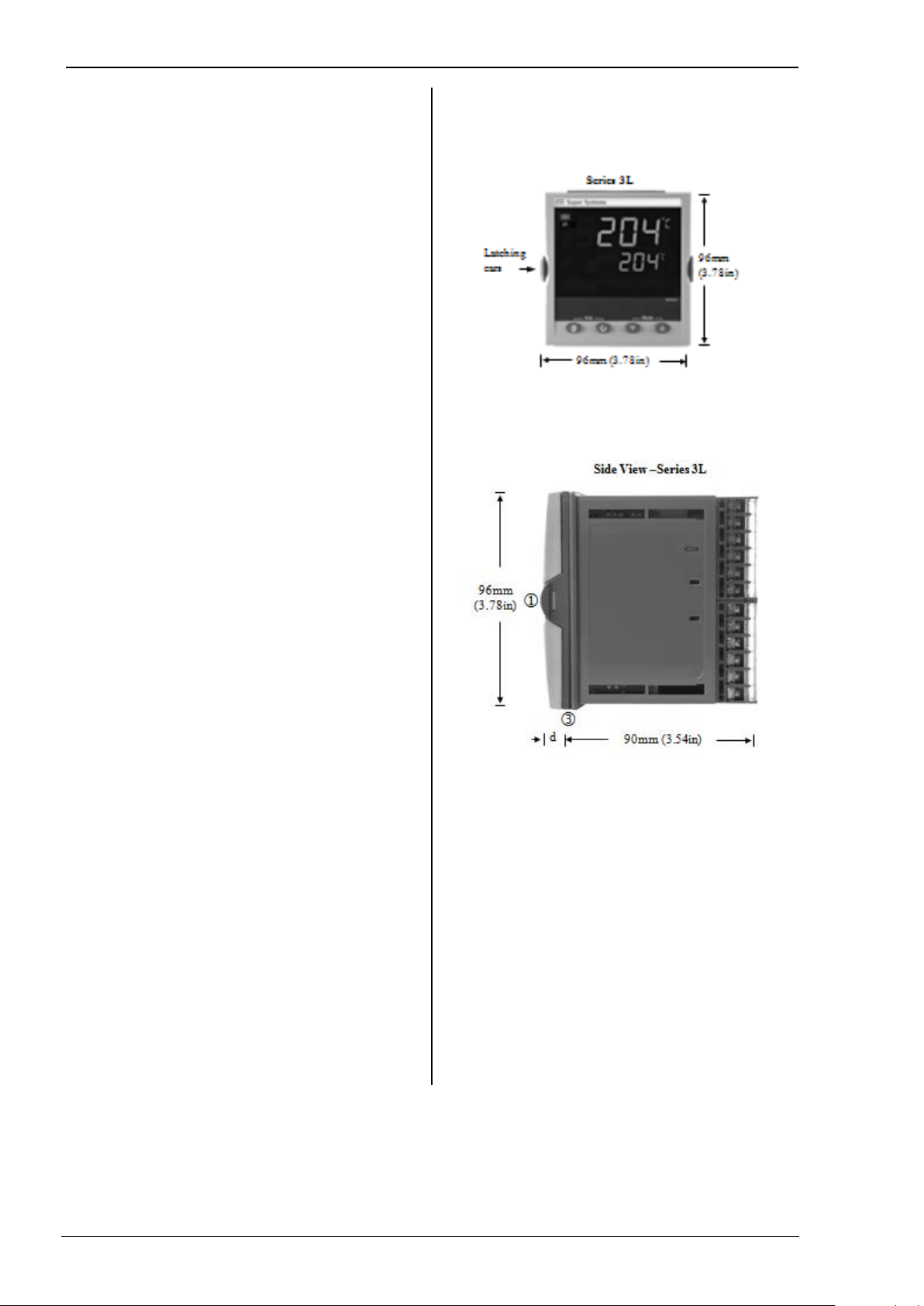
1.2 Dimensions Front Views
1.3 Dimensions – Side Views
Page 5
Series 3L Indicators
5
1.4 Step 1: Installation
10mm (0.4 inch)
This indicator is intended for permanent installation, for
indoor use only, and enclosed in an elect r i c al panel
Select a location which is subject to minimum
vibrations, the ambient temperatur e is within 0 and
o
C (32 - 131oF) and humidity 5 to 95% RH non
55
condensing.
The indicator can be mounted on a panel up to 15mm
thick
To ensure IP65 and NEMA 4 front sealing a gainst dust
and water, mount on a non-textured surface.
Please read the safety information in section 2 before
proceeding.
1.4.1 Panel Mounting the Indicator
1. Prepare a cut-out in the mo unting panel to the size
shown. If a number of instruments are t o be
mounted in the same panel, observe the minimum
spacing shown.
2. Fit the IP65 sealing gasket behind the front bezel of
the indicator.
3. Insert the indicator through the cut-out.
4. Spring the panel retaining clips into place. Secure
the indicator in position by holdin g i t level and
pushing both retaining clips forward.
5. Peel off the protective cover from the display
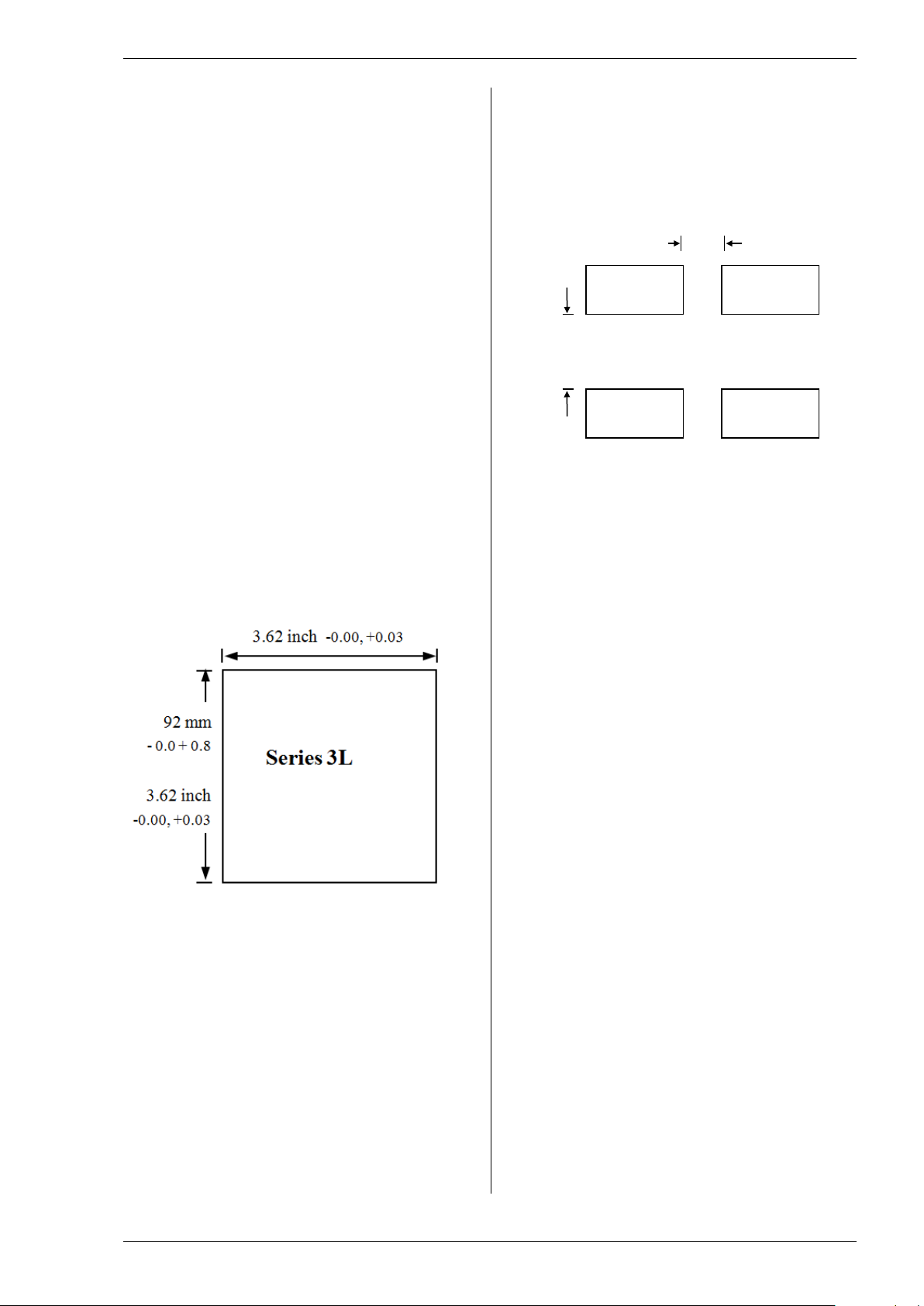
1.4.2 Panel Cut-out Sizes
1.4.3 Recommended Minimum Spacing of Indicators
Applies to all Model sizes
38mm (1.5 inch)
(Not to scale)
1.4.4 To Remove the Indicator from its Sl eeve
The indicator can be unplugged from its sleeve by
easing the latching ears outwards and pulling it forward
out of the sleeve. When plugging it back i nto its
sleeve, ensure that the latching ears click back into
place to maintain the IP65 sealing.
Page 6
Operations Manual Series 3L
6
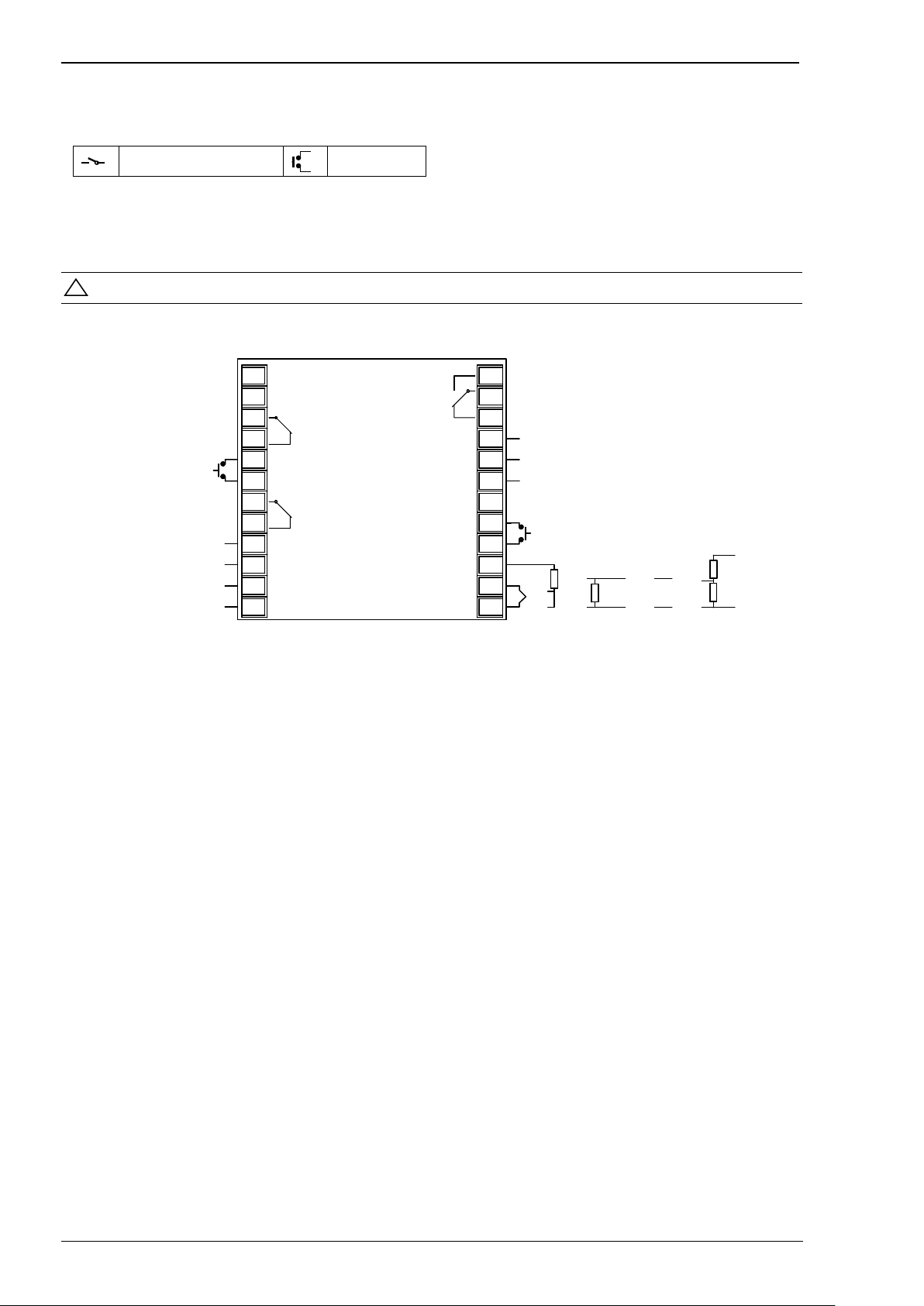
1.5 Step 2: Wiring
!
1A
1B
LB
LC
3A
3B
3C
3D
L
N
AA
AB
AC
HD
HE
HF
CT
C
LA
VI
V+
V-
Series 3L
+
24V
_
COM
A(+)
B(-)
Output 1 (OP1)
Digital Input B
Output 3 (OP3)
24V Transmitter Supply
Line Supply
100 to 230Vac ±15%
48 to 62 Hz
+
-
AA Relay (OP4)
FM RElay
Digital
Communications
EIA 485
Digital Input A
2.49
Ω
+
-
+
-
100K
Ω
806
Ω
+
-
10V Input
T/C Pt100 mA mV Vots
Sensor Input
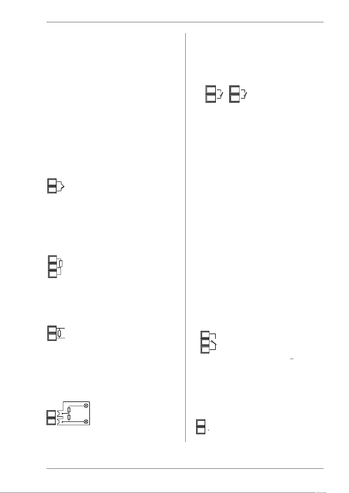
Key to Symbols used in the wiring diagrams
Relay Output
Contact Input
1.6 Terminal Layout Series 3L Indicators
Ensure that you have the correct supply for your indicator. Check order code of the indicator supplied
Page 7
Series 3L Indicators
7
1.7 Wire Sizes
100KΩ
+
V+
+
-
3C
VI
V+
2.49Ω
-
V+
OP4
AA
OP1
OP3
1A
3A
The screw terminals accept wire siz es from 0.5 to 1.5
mm (16 to 22AWG). Hinged covers prevent hands or
metal making accidental contac t with live wires. The
rear terminal screws should be tight ened to 0.4Nm (3.5
in-lbs).
1.8 Sensor Input (Measuring Input)
• Do not run input wires with power cables
• When shielded cable is used, it should be
grounded at one point only
• Any external components (such as zener barriers)
connected between sensor and input terminals
may cause errors in measurement due to
excessive and/or un-balanced line r esistance, or
leakage currents.
• Not isolated from the logic outputs & digital inputs
Thermocouple Input
+
Positive
V-
-
Negative
• Use the correct compensating cable, preferably
shielded.
• It is not recommended to connect two or more
instruments to one thermocouple.
RTD Input
V+
V-
• The resistance of the three wires mus t be the
PRT
PRT
Lead compensation
same. The line resistance may cause err ors if it
exceeds 22Ω.
Linear mA, or mV Inputs
+
V-
Positive
Negative
• For a mA input, connect the 2.49Ω bur den resistor
supplied between the V+ and V- ter m i nals as
shown. For mV, omit this resistor.
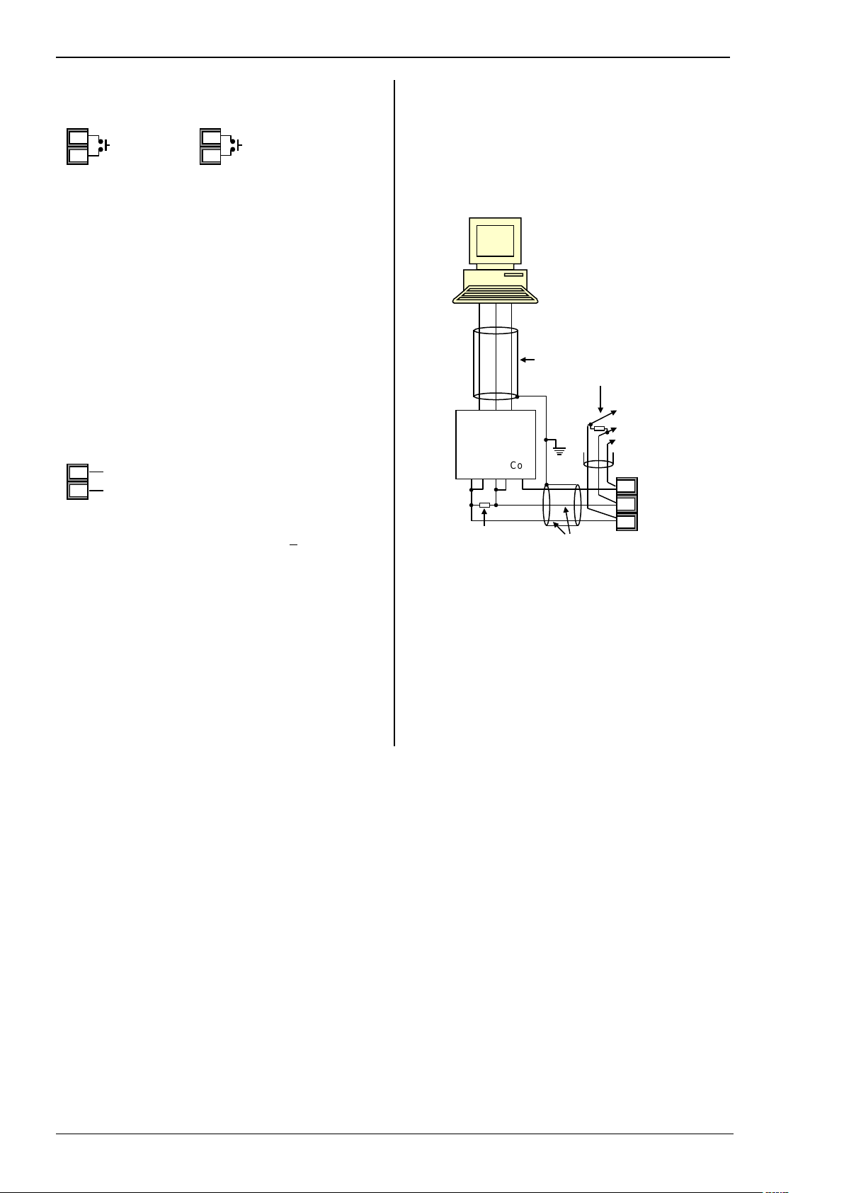
Linear Voltage Inputs
An external potential
0-10V
V-
806Ω
Input
-
Sensor break alarm does not operate if this adaptor is
fitted.
divider is required for the
Series 3L
1.9 Outputs
The indicators are supplied as standard with two
changeover relay outputs as follows:.
1.9.1 Output 1 & Output 3
Relay (Form A)
1B
3B
• Isolated output 300Vac CATII
• Contact rating:: 2A 264Vac resis tive
• Output functions: Alarm/Event
* General Notes about Relays and Inductive Loads
High voltage transients may occur when switching
inductive loads such as some contact ors or solenoid
valves. Through the internal contact s , these transients
may introduce disturbances which could affect the
performance of the instrument.
For this type of load it is recommended that a ‘snubber’
be connected across the normally open contact of the
relay switching the load. The snub ber recommended
consists of a series connected resistor/capacitor
(typically 15nF/100Ω). A snubber will also prolong the
life of the relay contacts.
A snubber should also be connected acr oss the output
terminal of a triac output to prevent f alse triggering
under line transient conditions.
WARNING
When the relay contact is open, or it is connected
to a high impedance load, it passes a current
(typically 0.6mA at 110Vac and 1.2mA at 230Vac).
You must ensure that this current will not hold on
low power electrical loads. If the load is of this
type, the snubber should not be connected.
1.9.2 AA Rela y Form C (FM Approved)
o Isolated output 300Vac CATII
o Software configurable: 0-20mA or 4-
20mA plus 0-5V, 0-10V, 1-5V and 2-
AB
AC
1.9.3 Transmitter Supply
A fixed 24Vdc supply is available to power an external
transducer
• Isolated output 300Vac CATII
3D
10V.
o Max load resistance: 500Ω
o Calibr ation accuracy: +(<0.25% of
reading + <50µA
Page 8
Operations Manual Series 3L
8
1.9.4 Digital Inputs A and B
Dig In A
LA
Dig In B
LB
* EIA232/ EIA485 2-
Com
Twisted pairs
Tx Rx Com
Rx Tx Com
Screen
RxB/
RxA/
*
HD Common
Line
L
C
LC
• Not isolated from the sensor input
• Switching: 12Vdc at 40mA max
• Contact open > 500Ω. Contact closed < 200Ω
• Input functions: Please refer to the l ist in the quick
codes.
1.10 Indicator Power Supply
1. Before connecting the indicator to the power line,
make sure that the line voltage corresponds to the
description on the identification label.
2. Use copper conductors only.
3. The power supply input is not fuse pr otected. This
should be provided externally.
4. For 24V, the polarity is not important.
N
• High voltage supply: 100 to 230Vac, +15%,
• Recommended external fuse ratings are as
Neutral
48 to 62 Hz
follows:
For 100 - 230Vac, fuse type: T rated 2A
250V.
1.11 Digital Communications (Optional)
Digital communications uses the Modbus protocol.
The interface is EIA485 (2-wire).
• Isolated 300Vac CATII.
EIA 485 Connections
TxB
220Ω termination
resistor
TxA
wire communications
converter eg Type
KD485
220Ω termination
resistor on last
instrument in the line
Daisy Chain
to further
instruments
HE Rx
HF Tx
Page 9

Series 3L Indicators
9
2. Safety and EMC Information
!
Caution (refer to accompanying documents)
This indicator is intended for industrial temperature and
process applications when it will m eet the
requirements of the European Direct ives on Safety and
EMC. Use in other applications, or failure to observe
the installation instructions of this handbook, may
impair safety or EMC. The installer must ensure the
safety and EMC of any particular installation.
Safety
This indicator complies with the E uropean Low Voltage
Directive 2006/95/EC, by the application of the safety
standard EN 61010.
Electromagnetic compatibility
This indicator conforms with the es s ential protection
requirements of the EMC Directive 2004/108/EC by the
application of a Technical Constr uction File. This
instrument satisfies the general requirements of the
industrial environment defined in EN 61326. For more
information on product compliance, refer to the
Technical Construction File.
GENERAL
The information contained in this manual is subject to
change without notice. While every effor t has been
made to ensure the accuracy of the information, your
supplier shall not be held liable f or errors contained
herein.
Unpacking and storage
The packaging should contain an inst rument mounted
in its sleeve, two mounting brackets for panel
installation and an Installation & Operating guide.
Certain ranges are supplied with an input adapter.
If on receipt, the packaging or the instrument is
damaged, do not install the product but c ontact your
supplier. If the instrument is to be stor ed before use,
protect from humidity and dust in an ambient
temperature range of -10OC to +70OC.
Service and repair
This indicator has no user serviceable parts. Contact
your supplier for repair.
Caution: Charged capacitors
Before removing an instrument f rom its sleeve,
disconnect the supply and wait at least two minutes to
allow capacitors to discharge. I t may be convenient to
partially withdraw the instrument from the sleeve, then
pause before completing the removal. In any case,
avoid touching the exposed elect r oni c s of an
instrument when withdrawing it from the sleeve.
Failure to observe these precautions m ay cause
damage to components of the instrume nt or some
discomfort to the user.
Electrostatic discharge precautions
When the indicator is removed from it s sleeve, some of
the exposed electronic components are vulnerable to
damage by electrostatic discharge from someone
handling the indicator. To avoid this, before handling
the unplugged indicator, disch ar ge yourself to a
ground.
Cleaning
Do not use water or water based products to clean
labels, or they will become illegible. Isopropyl alcohol
may be used to clean labels. A mild soap solution may
be used to clean other exterior surfaces of the product.
2.1 Installation Safety Requirements
Safety Symbols
Various symbols may be used on the in dicator. They
have the following meaning:
Equipment protected throughout by DOUBLE
INSULATION
Helpful hints
Personnel
Installation must only be carried out by suitably
qualified personnel in accordance with the instructions
in this handbook.
Enclosure of Live Parts
To prevent hands or metal tools from touc hi ng parts
that may be electrically live, the indicator must be
enclosed in an enclosure.
Caution: Live sensors
The indicator is designed to operate if the temperature
sensor is connected directly to an el ec trical heating
element. However, you must ensure that service
personnel do not touch connections t o these inputs
while they are live. With a live sensor, al l cables,
connectors and switches for connec ting the sensor
must be mains rated for use in 230Vac +15% CATII.
Wiring
It is important to connect the indicator in accordance
with the wiring data given in this guide. Take particular
care not to connect AC supplies to the low voltage
sensor input or other low level inputs and outputs.
Only use copper conductors for conn ec tions (except
thermocouple inputs) and ensure that the wiring of
installations comply with all local wiring regulations.
For example, in the USA, use NEC Class 1 wi ring
methods. In the UK, use the latest vers ion of the IEE
wiring regulations (BS7671).
Power Isolation
The installation must include a power isolating switch
or circuit breaker. This device should be in close
proximity to the indicator, within easy reach of the
operator and marked as the disconnecting device for
the instrument.
Overcurrent protection
The power supply to the system should be f used
appropriately to protect the cabli ng to the units.
Page 10

Operations Manual Series 3L
10
Voltage rating
The maximum continuous voltage applied between any
of the following terminals must not exceed 230Vac:
• relay output to logic, dc or sensor connections;
• any connection to ground.
The indicator must not be wired to a three phase
supply with an unearthed star connec tion. Under fault
conditions, such a supply could ri s e above 240Vac
with respect to ground, and the produc t would not be
safe.
Conductive pollution
Electrically conductive pollut ion must be excluded from
the cabinet in which the indicator is mount ed. For
example, carbon dust is a form of elect rically
conductive pollution. To secure a suitable atmosphere
in conditions of conductive pollution, fit an air filter to
the air intake of the cabinet. Where con densation is
likely—for example, at low temperatures—include a
thermostatically controlled heater in the cabinet.
This product has been designed to conform to
BSEN61010 installation category II, pollution degree 2.
These are defined as follows:
Installation Category II (CAT II)
For equipment on nominal 230V supply, the maximum
rated impulse voltage is 2500V.
Pollution Degree 2
Normally only non-conductive pollution occurs.
Occasionally, however, a temporary conductivity caused
by condensation shall be expected.
Grounding of the temperature sensor shield
In some installations, it is common practice to replace
the temperature sensor while the indicator is still
powered up. Under these conditions, as additional
protection against electric shoc k, we recommend that
the shield of the temperature sensor be grounded. Do
not rely on grounding through the f ramework of the
machine.
Over-temperature protection
When designing any control system, it is essential to
consider what will happen if any part of the system
should fail. In temperature control applications, the
primary danger is that the heating will remain
constantly on. Apart from spoiling the product, this
could damage any process machinery being
controlled, or even cause a fire.
Reasons why the heating might remain c onstantly on
include:
• the temperature sensor becoming detac hed from
the process
• thermocouple wiring becoming short circuit
• the controller failing with its heating output
constantly on
• an external valve or contactor sticking in the
heating condition
• the controller setpoint being set too high.
Where damage or injury is possible, we recommend
fitting a separate over-temperature protection unit, with
an independent temperature sensor , which will isolate
the heating circuit.
This indicator can be used in addition t o a controller as
an over-temperature device. It is recommended that
the relay used to indicate the alarm condition should
be set to high alarm configured with sensor break and
inverse ‘Inv’ operation so that it relax es to the alarm
condition when power is removed.
Installation requirements for EMC
To ensure compliance with the Europea n E MC
directive certain installation precautions are necessary
as follows:
• When using relay outputs it may be necessary to
fit a filter suitable for suppressing the emissions.
The filter requirements will depend on the type of
load.
• If the unit is used in table top equipment which is
plugged into a standard power socket, then it is
likely that compliance to the commerc i al and light
industrial emissions standard i s required. In this
case to meet the conducted emissions
requirement, a suitable mains filter should be
installed.
Routing of wires
To minimize the pick-up of electrical noise, the low
voltage DC connections and the sensor input wiring
should be routed away from high-current power cables.
Where it is impractical to do this, us e s hi elded cables
with the shield grounded at both ends. In general,
keep cable lengths to a minimum.
Page 11
Series 3L Indicators
11
3. Switch On
!
K C H C 0
o
(1)
(1)
(1)
(1) Up to 2 decimal places on Series 3L
3.1 New Indicator
If the indicator is new and has not previously been
configured, or following a ‘Cold Start’ (section 5.5), it
will start up showing the ‘Quick Configuration’ codes.
This is a built in tool which enables you to configure
the input type and range, the output functions, and the
display format.
Incorrect configuration can result in damage
to the process and/or personal injury and must be
carried out by a competent person authorized to
do so. It is the responsibility of the person
commissioning the instrument to ensure the
configuration is correct.
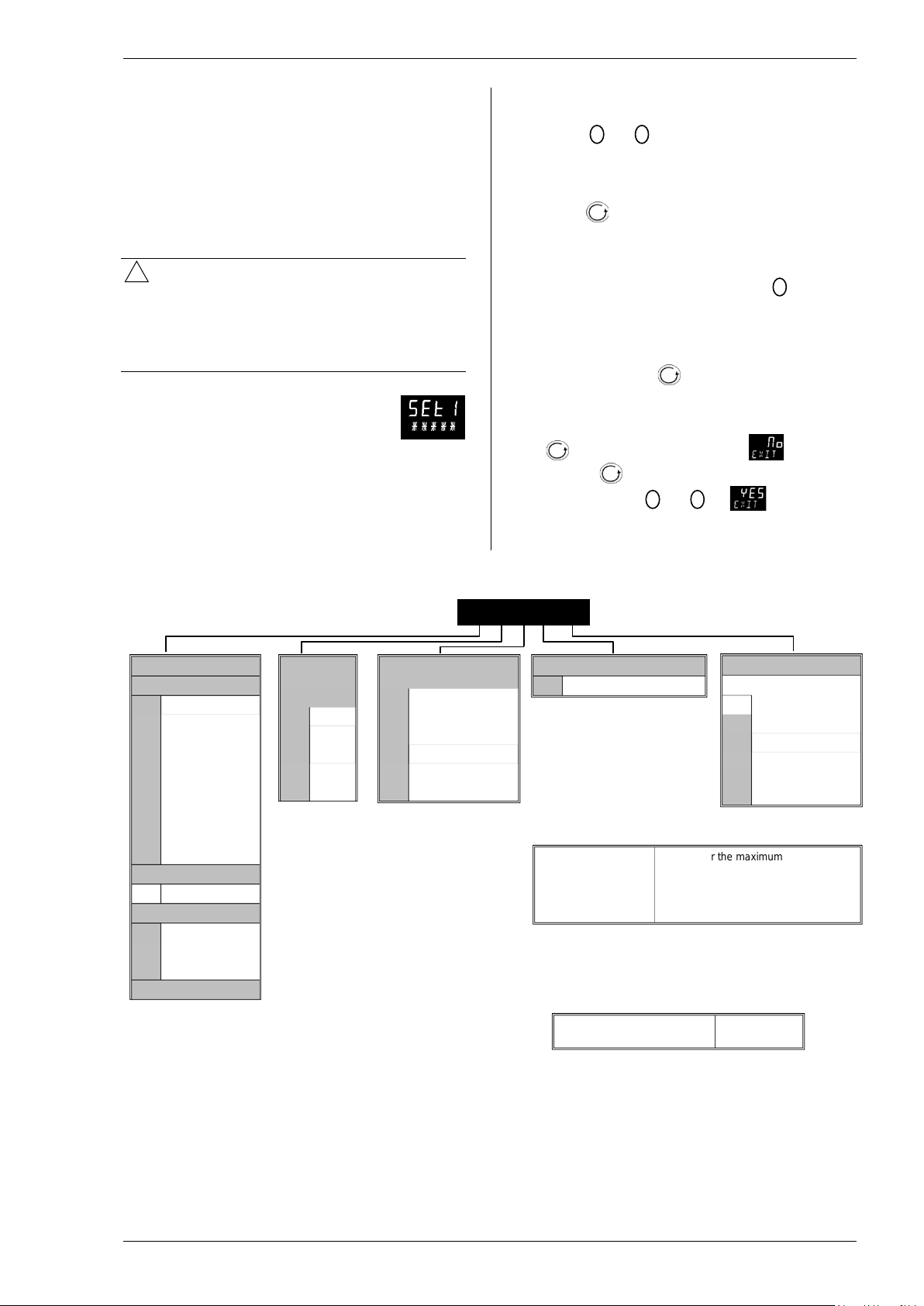
The quick code consists of two ‘SETS’
of five characters.
The upper section of the display shows the set
selected. The lower section sho ws the fi v e digits which
make up the set.
Adjust these as follows:
SET 1
Input Type
Thermocouple
B Type B
J Type J
K Type K
L Type L
N Type N
R Type R
S Type S
T Type T
C Custom C
RTD
P Pt100
Linear (all units)
M 0-80mV
2 0-20mA
4 4-20mA
Display
units
Temperature
X None 1 nnnn.n
C
F oF 3 nn.nnn
K K 4 n.nnnn
P %
Decimal point
0 nnnnn
C 2 nnn.nn
(1)
1. Press any button. The first charac ter will change
to a flashing ‘-‘.
2. Press
or
to change the flashing character
to the required code shown in the quick c ode
tables –see next page. Note: An
x indicates that
the option is not fitted.
3. Press to scroll to the next ch aracter.
You cannot scroll to the next character until the
current character is configured.
To return to the first character press
4. When all five characters have been conf i gured the
display will change to rng.hi followed by rng.lo
which allows range high and low limits to be set.
5. The next press of will select Set 2. Adjust
each character as described for Set 1.
6. When the last character has been entered press
again; the display will show . Continue
to press if you wish to repeat the above quick
or
codes or press
satisfied with the quick codes. The indicator will
then automatically go to the operator level
Not Applicable
(1)
X Not applicable
Set 1 is followed Set this for the maximum
with RNG.HI display range required
Then Set this for the minimum
RNG.Lo display range required
Set 2 follows these
parameters
to if you are
Home display
N PV only
A First Alarm SP only
1 PV + Alarm SP
2 PV + Alarm SP
See next page
.
(Read only)
Page 12
Operations Manual Series 3L
12
Page 13
Series 3L Indicators
13
3.1.1 To Re-Enter Quick Code Mode
If you need to re-enter the ‘Quick Configuration’ m ode
this can always be done as follows:
1. Power down the indicator.
3.3 Front panel layout
2. Hold
button down and power up the indicat or
again. Keep the button pressed until you are
requested to enter a passcode.
3. Enter a passcode using the
or
buttons. In
a new indicator the passcode defau l ts to 4. If an
incorrect passcode is entered, you must repeat
the whole procedure.
Parameters may also be configured using a
deeper level of access as described in subsequent
chapters of this manual. If this has been done and the
Quick Code Mode is re-entered as descri bed above,
then the quick codes are shown with full stops (e.g.
G.S.2.G.A.) to indicate that the conf iguration has been
changed.
3.2 Pre-Configured Indicator or Subsequent Starts
A brief start up sequence consists of a self test in
which all elements of the display are illuminated and
the software version number is shown.
The indicator will briefly displa y the quick codes during
start up and then proceed to Operator Level 1.
You will see the display shown below. It is called the
HOME display.
If the Quick Codes do not appear during start up,
this means that the indicator has been configured in a
deeper level of access, as stated opposite. The quick
codes may then not be valid and are therefore not
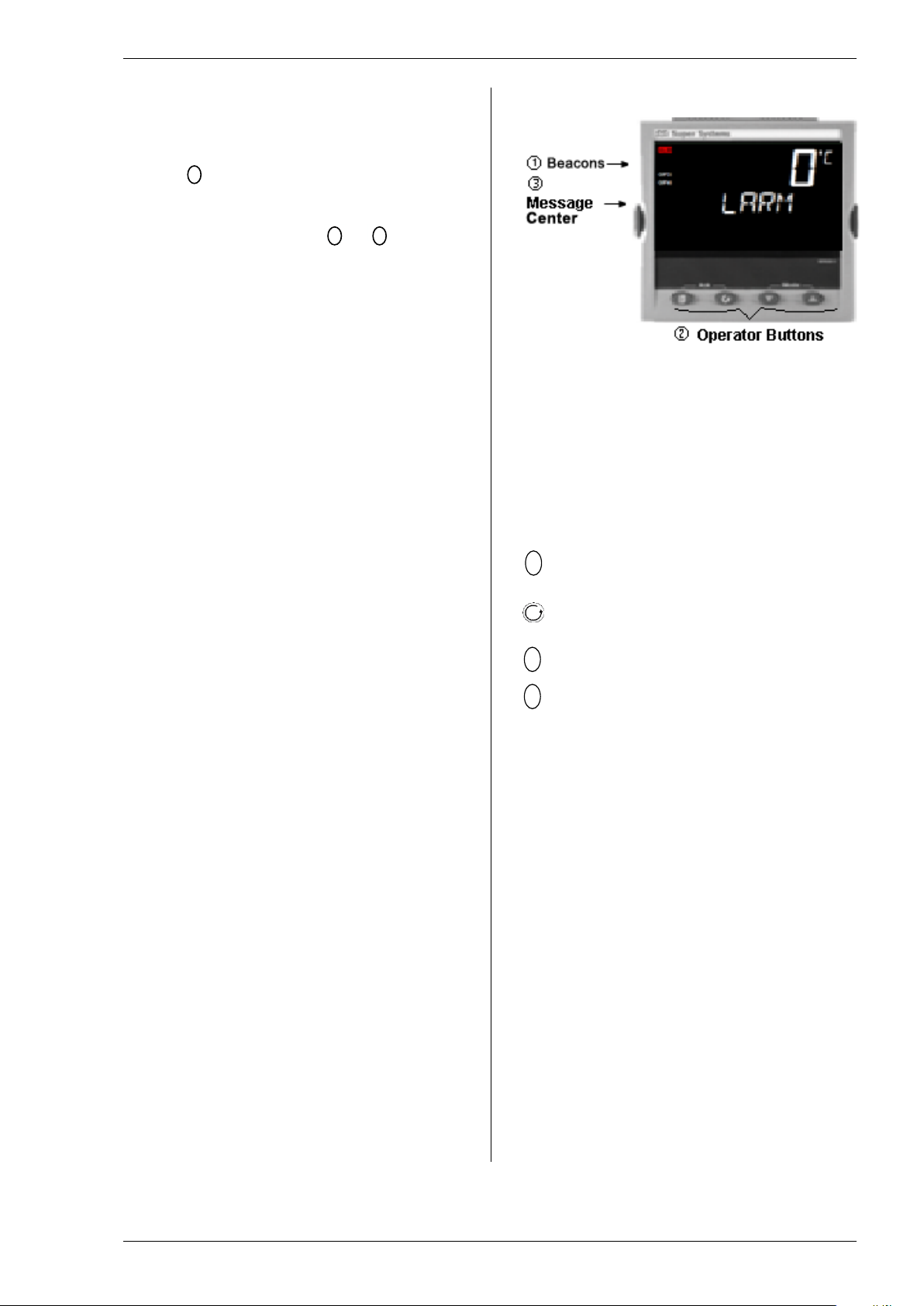
shown.
Beacons
ALM Alarm active (Red)
OP1 Lit when output 1 is ON
OP3 Lit when output 3 is ON
OP4 Lit when output 4 (AA relay) is ON
REM Communications active
Operator Buttons:
From any display - press to return to the HOME
display.
Press to select a new parameter. Hold down to
continuously scroll through parameters.
Press to change or decrease a value.
Press to change or increase a value.
Message Center
A scrolling message may appear in this section. For
example, if a high alarm is configured to operate output
1, and a low alarm is configured to operate output 4,
the scrolling messages ‘ALARM 1 HIGH’ and ‘ALARM
4 LOW’ are shown together with the beac ons ‘ALM’,
‘OP1’ and ‘OP4’. ‘ALM’ flashes if the alarm has not
been acknowledged.
If the input sensor is broken ‘S.br’ appear s in the top
display and the scrolling message ‘INPUT SENSOR
BROKEN’ appears in the message center.
Page 14

Operations Manual Series 3L
14
3.3.1 Alarm Indication
Parameter
Scrolling
Description
Availability
HIGH
PEAK HIGH
This is the highest reading
LOW
PEAK LOW
This is the lowest reading
or since it was reset
SETPOINT
SETPOINT
ALARM 3
SETPOINT
A4 (----)
ALARM 4
SETPOINT
Up to three alarms can be configured. If any alarm
occurs, the red ALM beacon will flas h. A scrolling text
message will describe the source of the alarm (for
example, ALARM 1 HIGH). Any output attached to the
alarm will operate.
Press
and (Ack) together to acknowledge the alarm
If the alarm is still present, the ALM beacon will light
continuously.
By default alarms are configured as non-latching, deenergized in alarm. If you require lat ched alarms,
please refer to the engineering handbook.
3.3.2 Out of Range Indication
If the input is too high, HHHHH will be displayed.
If the input is too low, LLLLL will be displayed.
3.3.3 Sensor Break Indication
An alarm condition (S.br) is indicated if the sensor or
the wiring between sensor and indicator becomes
open circuit.
For a PRT input, sensor break is indicated if any one of
the three wires is broken.
For mA input, sensor break will not be detected due to
the load resistor connected across the input terminals.
For Volts input, sensor break may not be detected due
to the potential divider network connec ted across the
input terminals.
3.4 Operator Parameters in Level 1
Operator level 1 is designed for day to day operation of
the indicator, and access to these parameters is not
protected by a pass code.
Press
to step through the list of parameters. The
mnemonic of the parameter is sho wn in t he lower
display. After five seconds, a scrolling text description
of the parameter appears.
The value of the parameter is shown in the u pper
display. In level 1 the value is read onl y.
The parameters that appear depend upon the
functions configured. They are:
Mnemonic
A1 (----) ALARM 1
A2 (----) ALARM 2
A3 (----)
text and
that the indicator has
recorded since switch on
or since it was reset
that the indicator has
recorded since switch on
(----) shows the type of
alarm configured. For
example: HI, LO, ROC.
This parameter sets the
alarm thresholds.
Page 15
Series 3L Indicators
15
4. Operator Level 2
Level 2 provides access to additional parameters. It is
protected by a security code.
4.1 To Enter Level 2
1. From any display press and hold
2. After a few seconds the
display will show:-
3. Release
.
(If no button is pressed for 45 seconds the
display returns to the HOME display)
4. Press
or
to
choose Lev 2 (Level 2)
5. After 2 seconds the
dis play will show:-
6. Press
pass code. Default = ‘2’
or
to enter the
7. If an incorrect code is entered the indicator reverts
to Level 1.
4.1.1 To Return to Level 1
1. Press and hold
.
4.2 Level 2 Parameters
As in Level 1, press to step throu gh the list of
parameters.
in the message center. After five seconds, a scrolling
text description of the parameter appears.
The value of the parameter is shown in the upper
display. Press
If no key is pressed for 30 seconds, the indicator
returns to the HOME display.
Backscroll is achieved when you are in this list by
pressing
To return to the HOME display at any time, press
The following table shows a list of parameters
available in Level 2.
The mnemonic of the parameter is shown
or
to adjust this value.
while holding down .
.
2. Press
to select LEv 1
The indicator will return to the level 1 HOME display.
Note: A pass code is not required when goi ng from a
higher level to a lower level.
Page 16

Operations Manual Series 3L
16
Mnemonic Scrolling Display and description Range
has recorded since switch on or since it was reset
Read only
has recorded since switch on or since it was reset
A1 (----)
ALARM 1 SETPOINT
(----) shows the type of alarm configured. For example
A2 (----)
ALARM 2 SETPOINT
ALARM 3 SETPOINT
A4 (----)
ALARM 4 SETPOINT
ADDR
ADDRESS Digital communications address for the
instrument (if digital communications fitted)
1 to 254
HOME
HOME DISPLAY This configures the parameter which
Process variable
PV + Alarm SP
PV + Alarm SP read only
number
O
O
O
PRST
PEAK RESET Select On to reset the HIGH and LOW peak
values. The display automatically returns to OFF
OFF
ON
HIGH PEAK HIGH This is the highest reading that the indicator
LOW
PEAK LOW This is the lowest reading that the indicator
Read only
HIGH, LOW,
A3 (----)
will be displayed in the HOME display in normal
operation
ALm
pv.aL
p.a.ro
PV
ID CUSTOMER ID Customized instrument identification
0 to 9999
UNITS DISPLAY UNITS The display units are shown in the top right hand
corner of the display in normal operation. Units available are:-
O
C
none
C
No units displayed
O
F
Perc
F
Percentage
Press
at any time to return immediately to the HOME screen at the top of the list.
Hold down to continuously scroll through the above list
Alarm setpoint
k
Kelvin
Page 17

Series 3L Indicators
17
4.3 FM and Alarm Units
!
Series 3L indicators supplied to Function code FM are
FM approved.
Series 3L indicators supplied to Function code DN are
approved to EN14597.
The instrument label is marked accordingly.
In these instruments, the alarm operating the AA relay
output is set to inverted and latching. This function
cannot be altered.
When the instrument is configured using the Quick
Start codes (section 3.1), Alarm 1 is used to operate
both Outputs 1 and 4 (AA relay). The Quick Start
configuration for the AA relay will enable and configure
Alarm 4 but Alarm 4 will not be used to operate Output
4.
If Quick Start is used to configure Alarm 1 as
a high alarm and Alarm 4 as a low alarm, then the
resulting configuration will be t hat the high alarm 1 is
used to drive both outputs 1 and 4. The low alarm 4
will not be connected to any output.
Further details on latching and blocking alarms can be
found in section 9.1.
4.4 Recipes
Not Applicable to this Instrument
Page 18

Operations Manual Series 3L
18
5. Access to Further Parameters
Parameters are available under different levels of
security and are defined as Level 1 (Lev1), Level 2
(Lev2), Level 3 (Lev 3) and Configuration (Conf).
Level 1 has no pass code since it contains a minimal
set of parameters generally sufficient to run the
process on a daily basis. Level 2 allows access t o
parameters which may used in commissioning an
indicator or settings between different products or
batches. This has been described in the previous
section.
Level 3 and Configuration level parameters are also
available as follows:
5.1 Level 3
Level 3 makes all operating parameters available and
alterable (if not read only). It is typically used when
commissioning an indicator.
Examples are:
Range limits, setting alarm levels, communications
address.
5.2 Configuration Level
This level makes available all par ameters including the
operation parameters so that there is no need to switch
between configuration and operati on levels during
commissioning. It is designed for those who may wish
to change the fundamental characteristics of t he
instrument to match the process.
Examples are:
Input (thermocouple type); Alarm type;
Communications type.
WARNING
Configuration level gives access to a wide range of
parameters which match the indicator to the
process. Incorrect configuration could result in
damage to the process and/or person al injury. It is
the responsibility of the person commissioning the
process to ensure that the configuration is correct.
In configuration level, the indicator is not providing
alarm indication.
Do not select configuration level on a live process.
Operating
Level
Level 1
Level 2
Level 3
Conf
Home
List
Full
Operator
Yes RW
Yes RO
Configuration Alarms
Yes
No
Page 19

Series 3L Indicators
19
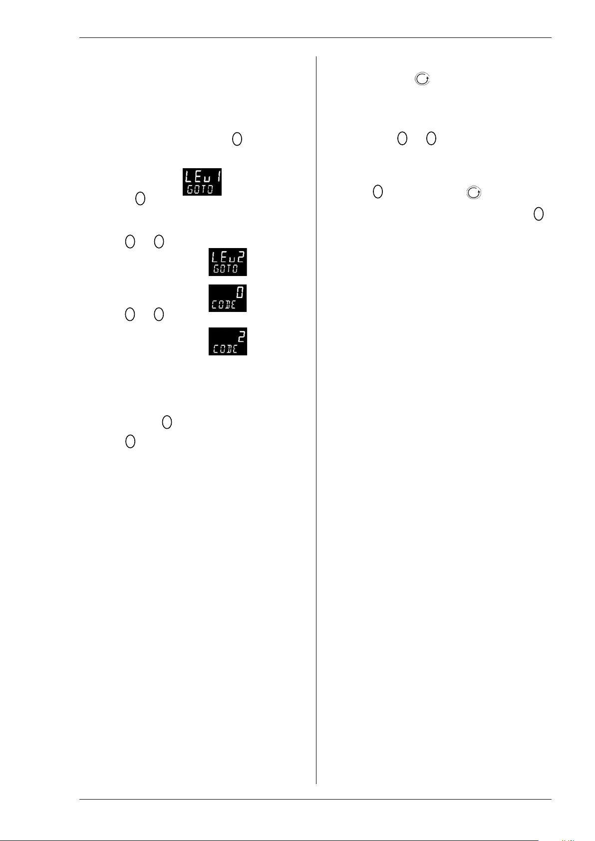
5.2.1 To Select Access Level 3 or Configuration Level
Do This
The Display You Should See
Additional Notes
To Select Level 3
The default code is 3:
appear – see section 9.4 ‘Diagnostic Alarms’
3
Lev 3
0
Conf
0
Conf
4
Conf
Lev1
1. From any display press and
hold
seconds
2. Press
passcode for Level 3
3. When the LEV3 GOTO view is
shown, as in paragraph 1
above, press
‘Conf’
4. Press
passcode for Configuration
level
5. Press and hold
than 3 seconds
6. Press
required level—for example,
LEV 1
for more than 5
or
to enter the
to select
or
to enter the
to select the
for more
goto
code
To Select Configuration
code
level
goto
code
code
To Return to a Lower Level
goto
goto
The display will pass from the current operating
level, for example, Lev 1 to Lev 3 as the button
is held down.
(If no button is then pressed for about 50 seconds
the display returns to the HOME display)
If an incorrect code is entered the display reverts to
‘goto’.
If a correct code is entered the indicator is now in the
level 3 will then revert to the HOME display
Note:
indicator requests the code for level 3
The default code is 4:
If an incorrect code is entered the display reverts to
‘goto’.
If a correct code is entered the indicator is now in
Configuration level will now show Conf
The choices are:
LEv 1 Level 1
LEv 2 Level 2
LEv 3 Level 3
ConF Configuration
It is not necessary to enter a code when going from
a higher level to a lower level.
Alternatively, press
header, then press to select the required level.
The display will then flash ‘ConF’ for a few seconds
and the indicator will then go through its start up
sequence, starting in the level selected.
Do not power down while Conf is flashing. If a
power down does occur an error message will
must be pressed quickly before the
and scroll to the Acces list
A special case exists if a security code has been
configured as ‘0’ If this has been done i t is not
necessary to enter a code and the indicat or will enter
the chosen level immediately.
When the indicator is in configuration level the
ACCESS list header can be selected from any view by
holding down the
Then press
button for more than 3 seconds.
again to select ‘ACCES’
Page 20
Operations Manual Series 3L
20
5.3 Parameter lists
Parameters are organized in lists. The top of the list
shows the list header only. The name of the list
header describes the generic funct i on of the
parameters within the list. For example, the list header
‘ALARM’ contains parameters which enable you to set
up alarm conditions.
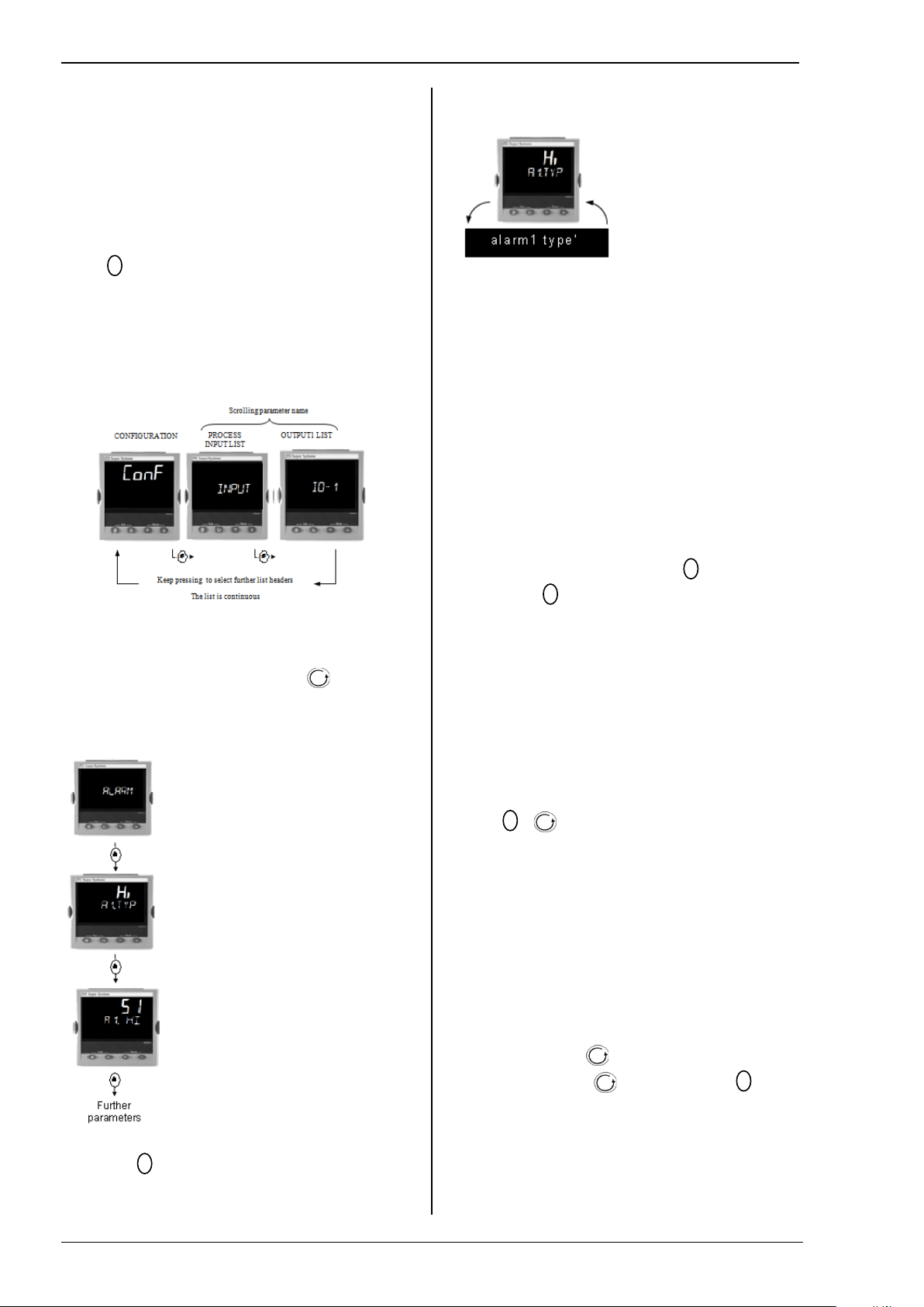
5.3.1 To Choose Parameter List Headers
Press
time this key is pressed.
The name of the list header appears in the lower
display, followed, after a few seconds, by a scrolling
longer description of the name.
The following example shows how to select the first
two list headers.
. Each list header is selected in turn every
5.3.3 How Parameters are Displayed
As shown above. Whenever a
parameter is selected it is displaye d as a mnemonic, of
four or five characters, for example ‘A1.TYP’.
After a few seconds this display is replaced by a
scrolling banner which gives a mor e detailed
description of the parameter. In thi s example ‘A1.TYP’
= ‘alarm 1 type’. The scrolling banner is onl y shown
once after the parameter is first acc essed.
The name of the list header is also displayed in this
way.
The upper part of the display shows the value of the
parameter.
The lower part shows its mnemonic foll owed by the
scrolling name of the parameter
5.3.4 To Change a Parameter Value
5.3.2 To Locate a Parameter
Choose the appropriate list, then press . Each
parameter in the list is selected in tur n each time this
button is pressed. The following example shows how
to select the first two parameters in t he ALARM List.
All parameters in all lists follow the same procedure.
With the parameter selected, press
value, press
held down the analogue value changes at an
to decrease the value. If either key is
to increase the
increasing rate.
The new value is entered after the key is released and
is indicated by the display blinking. The exception to
this is output ‘Power’ when in manual. In this case the
value is entered continuously.
The upper display shows the paramet er value the
lower display shows the parameter name.
5.3.5 To Return to the HOME Display
Press
+ .
On release of the keys the display returns to the
HOME list. The current operating level r emains
unchanged.
5.3.6 Time Out
A time out applies to the ‘Go To’ and ‘Control Mode’
parameters. If no key presses are detec ted within a
period of 5 seconds the display will rev ert back to the
HOME list.
Press and hold to scroll parameters forward
through the list. With depressed, press
scroll parameters backward.
Press
to jump back to the list header.
to
Page 21
Series 3L Indicators
21
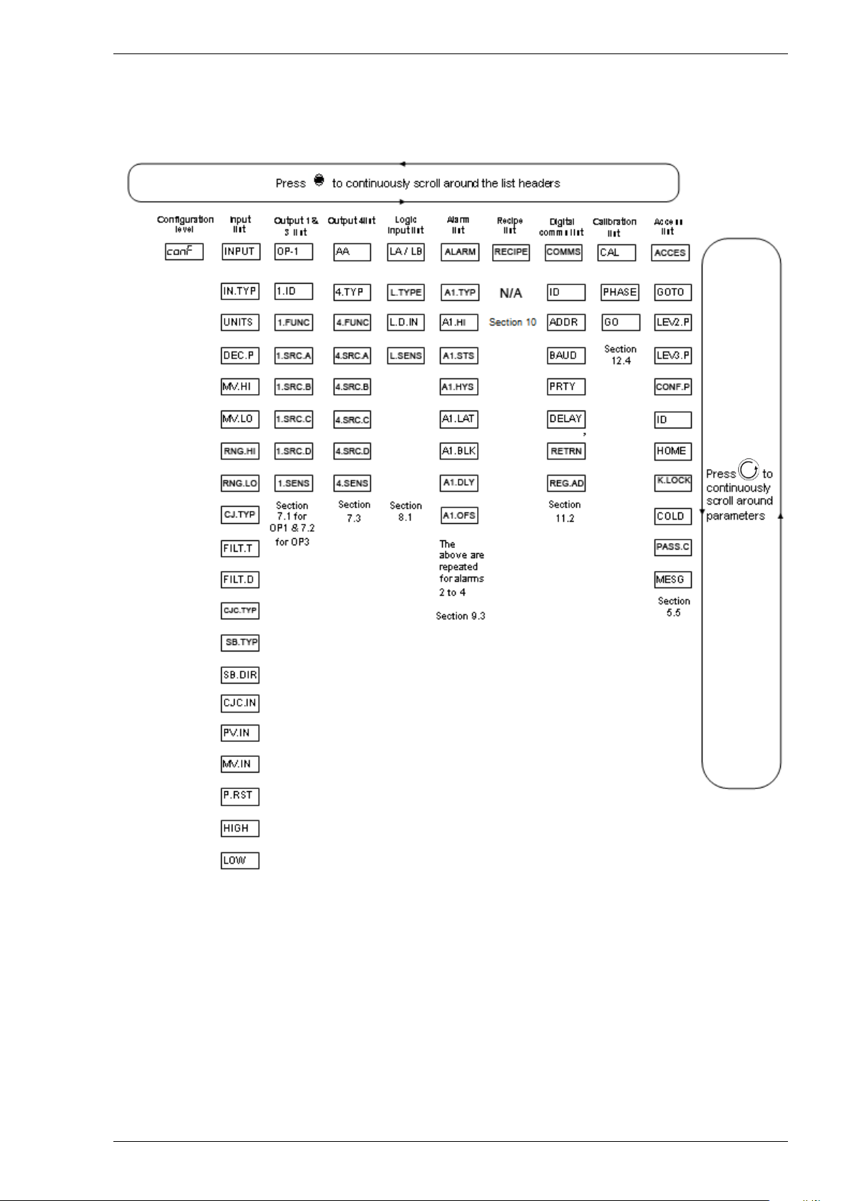
5.4 Navigation Diagram
The diagram below shows the all list h eadings available in configuration level for Series 3L indicator.
The parameters in a list are shown in t ables in the following sections of t his manual together with explanati ons of their
meanings and possible use.
Lists may vary depending on the type of input and options configured. For example CJC.TYP and CJC.IN only
appear if the Input Type is a thermocouple.
Page 22
Operations Manual Series 3L
22
5.5 Access Parameters
!
ACCESS LIST
‘ACCS’
Name
Scrolling
Display
Parameter Description
Values Allowed
Default
Access
Level
GOTO
GOTO
Allows you to change the access level
Operator level 1
Conf
Operator level 2
Operator level 3
Configuration level
LEV2.P
LEVEL 2
PASSCODE
The Level 2 passcode
Conf
LEV3.P
LEVEL 3
PASSCODE
The Level 3 passcode
Conf
CONF.P
CONFIG
PASSCODE
To set a Configuration level passcode
Conf
ID
CUSTOMER
ID
To set the identification of the indicator
Conf
HOME
HOME
To configure the parameters to be
Process Value – top display
Conf
section
PV - top display
only in lower section
K.LOCK
KEYBOARD
To limit operation of the front panel
normal.
Unlocked
Conf
All buttons locked
Edit keys locked
COLD
COLD START
Use this parameter with care.
power up
Disable
Conf
Enable
PASS.C
FEATURE
To enable chargeable options
Conf
MESG
STATIC HOME
Up to 15 messages can be configured.
The HOME display is
Conf
Message 15
The following table summarizes the par ameters available under the ACCESS list header
The Access List can be selected at any tim e when in configuration level by holding
seconds, then press
DISPLAY See
Note 1
or
with
still held down. Use the button to sc roll through the menu options.
of the indicator. Passwords prevent
unauthorized change
displayed in the HOME display
Lev.1
Lev.2
Lev.3
Conf
0-9999
0 = no passcode will be requested
0-9999
pV
Blank lower display
aLm
First configured alarm – top
Blank lower display
pV.aL
PV - top display
First configured alarm in lower
p.a.ro
First configured alarm read
key down for 3
Le
v.
1
2
3
4
St
d
LOCK
ENABLE/
DISABLE
PASSCODE
MESSAGE
The following sections in this handb ook describe the parameters associated with each subject. The general format of
these sections is a description of the subject, followed by the table of all parameters to be found in the list, followed by
an example of how to configure or set up parameters.
buttons when in operator levels.
If ALL has been selected, then to
restore access to the keyboard, cycle
power to High Limit with the
button held down and enter the
configuration level passcode as
described in section 3.1.1
take you to the Quick Code mode.
Press to scroll to the EXIT option
and select YES. The front panel
buttons can then be operated as
When set to yes the indicator will
return to factory settings on the next
This parameter calls up messages 1 to
15.
. This will
none
ALL
Edit
No
YES
OFF
1 to
15
none
Off
configured according to the
parameter HOME above
Message 1
Page 23

Series 3L Indicators
23
Input Type and
Thermocouple (TC) and 3-wire resistance thermometer (RTD) temperature detectors
See the table in section 6.1.1. for the list of input types available
Display units and
resolution
The change of display units and resolution will all the parameters related to the process
variable
Input filter
First order filter to provide dampin g of the input signal. This may be necessary to prevent
indication. More typically used with linear process inputs.
Fault detection
Sensor break is indicated by an alarm message ‘Sbr’. For thermocouple i t detects when
than 12Ω.
User calibration
Either by simple offset or by slope and gain. See section 12.2. for further details.
Over/Under range
When the input signal exceeds the input span by more than 5% the PV will flash
decimal point.
INPUT LIST
I NPUT
L3 R/O
UNITS
DISPLAY
Display units shown on the
No units - only for custom
linearisation
L3
For a full list of units see section 6.1.2.
DEC.P
DISPLAY
Decimal point position
Conf
INP.LO
LINEAR
INPUT LOW
Low limit for mV (mA) inputs
-10.00 to +80.00mV
Conf
RNG.HI
RANGE HIGH
Range high limit for
inputs
From the high limit of the selected input
minus one display unit.
Conf
RNG.LO
RANGE LOW
Range low limit for
From the low limit of the selected input
Conf
See section 6.1.3.
FILT.T
FILTER TIME
Input filter time constant
(first order digital filter)
OFF to 100.0 seconds
L3
FILT.D
DISPLAY
Provides a filter for the
No display filter
L3
Zero the least significant digit
Zero the two least significant digits
CJ.TYP
CJC TYPE
Configuration of the CJC
thermocouple inputs)
Automatic
Conf and if
Fixed at 50oC
No sensor break will be detected
Open circuit sensor will be
Latching
SB.DIR
SENSOR
BREAK
Defines the direction in
which the PV will range.
Up scale. Output goes to
maximum
Conf
6. Process Input
Parameters in the input list configure the input to match your sensor. These parameters provide the foll owing
features:-
linearization
Linear input (-10 to +80mV) through external shunt or voltage divider, m A assumes a
2.49Ω external shunt.
the effects of excessive process noise on the PV input from causing poor c ontrol and
the impedance is greater than pre-def ined levels; for RTD when the resistance is less
indicating under or over range. If the value is too high to fit the number of characters on
the display ‘HHHH’ or ‘LLLL’ will fl as h. The same indications apply when the display is
not able to show the PV, for example, when the input is greater than 999.9oC with one
6.1 Process Input Parameters
Name Scrolling
Display
IN.TYP INPUT TYPE Selects input linearization
UNITS
Parameter Description Value Default Access
and range
instrument
See section 6.1.1. for input types available
none
Level
o
C
Conf
POINTS
INP.HI LINEAR
INPUT HIGH
LIMIT
LIMIT
(1) See section 6.1.3 for an example of how to adjust the above four parameters.
PV.OFS PV OFFSET A simple offset applied to all
FILTER
SB.TYP SENSOR
BREAK TYPE
High limit for mV (mA) inputs
(1)
(1)
thermocouple RTD and mV
(1)
thermocouple RTD and mV
(1)
inputs
input values.
displayed value
type
(only shown for
Defines the action which is
applied to the output if the
sensor breaks (open circuit)
nnnnn - No decimal point to n.nnnn - four
decimal points
-10.00 to +80.00mV
type to the ‘Low Range Limit’ parameter
type to the ‘High Range Limit’ parameter
minus one display unit.
Generally one decimal point more than PV
Off
1
2
Auto
0oC
50oC
oFF
on
Lat
up
Fixed at 0oC
detected
nnnnn
80.00
-10.00
1.6
Off
Auto
on
up
L3 R/O
Conf
L3 R/O
L3 R/O
L3
T/C
L3 R/O
Conf
L3 R/O
Page 24

Operations Manual Series 3L
24
DIRECTION
Dwn
Down scale. Output goes to
minimum
CJC.IN
CJC
Temperature measured at
thermocouple inputs)
Read only
Conf
PV.IN
PV INPUT
VALUE
Current measured
temperature
Minimum display to maximum display range
Conf
MV.IN
MILLIVOLT
INPUT VALUE
Millivolts measured at the
rear PV Input terminals
xx.xx mV - read only
P.RST
PEAK RESET
Select ON to reset the HIGH
since it was reset
HIGH
PEAK HIGH
This is the highest reading
Read only
L1
o
o
o
o
o
o
o
o
o
o
o
C
o
F
Kelvin
No units displayed
Percentage
TEMPERATUR
E
the rear terminal block.
Used in the CJC calculation
(only shown for
and LOW peak values. The
display automatically returns
to OFF
LOW PEAK LOW This is the lowest reading
that the indicator has
recorded since switch on or
that the indicator has
recorded since switch on or
since it was reset
6.1.1 Input Types and Ranges
Input Type Min
J.tc
k.tc
L.tc
r.tc
b.tc
n.tc
t.tc
S.tc
rtd
mv
Cms
Thermocouple type J -210 1200
Thermocouple type K -200 1372
Thermocouple type L -200 900
Thermocouple type R -50 1700
Thermocouple type B 0 1820
Thermocouple type N -200 1300
Thermocouple type T -200 400
Thermocouple type S -50 1768
Pt100 resistance thermometer -200 850
mV or mA linear input -10.00 80.00
Value received over digital communications (modbus address 203).
This value must be updated every 5 seconds or the indicator will show sensor break
6.1.2 Units
O
C
none
O
F
Perc
OFF
On
Read only
Range
O
k
Max
Range
peak
Values
reset
Unit
s
o
C -238 2192
Min
Range
C -238 2498
C -238 1652
o
C -58 3124
o
C -32 3308
C -238 2372
C -238 752
o
C -58 3214
C -238 1562
Max
Range
L3 R/O
and if T/C
L3 R/O
OFF
L1
Unit
s
o
F
F
F
o
F
o
F
F
F
o
F
F
Page 25
Series 3L Indicators
25
Notes
Scrolling display
to ‘
Scrolling display
to ‘
Scrolling display
In operator level
to ‘
2.0
mv
500.0
2.0
For mA inputs
inp.lo eg
Electrical Input
Display
RNG.HI
Rng.lo
inp.hi
Electrical Input
Display
Fixed offset
Factory
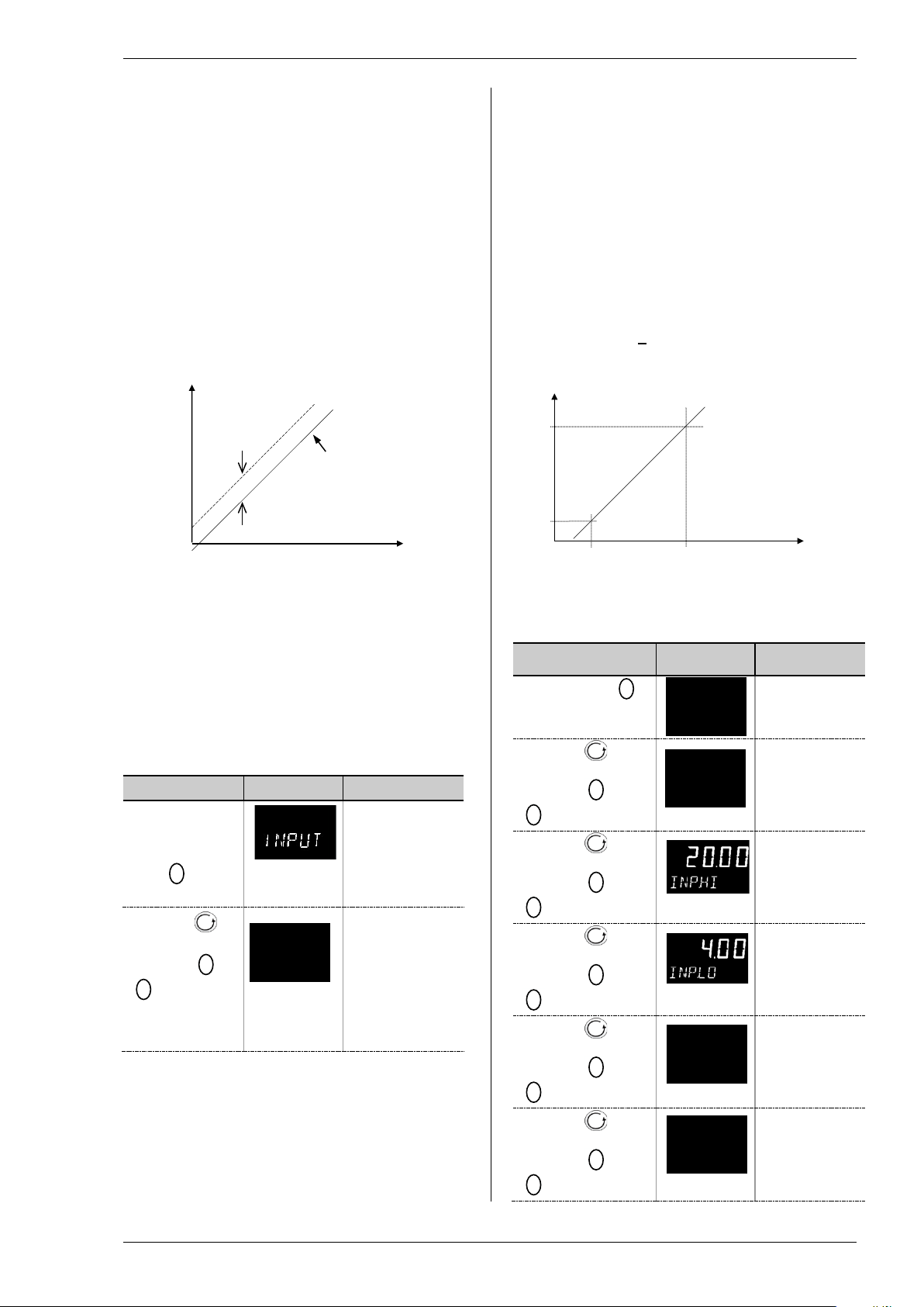
6.1.3 PV Offset
All ranges of the indicator have been calibrated against
traceable reference standards . This means that if the
input type is changed it is not necessary to calibrate the
indicator. There may be occasions, however, when you
wish to apply an offset to the standard calibration to
take account of known errors within th e pr ocess, for
example, a known sensor error or a known error due to
the positioning of the sensor. In these i ns tances it is
not advisable to change the referenc e ( factory)
calibration, but to apply a user defined offset.
PV Offset applies a single offset t o the temperature or
process value over the full display range of the indicator
and can be adjusted in Level 3. It has the effect of
moving the curve up a down about a central point as
shown in the example below:-
Reading
(e.g. 2)
calibration
6.1.3.1 Example: To Apply an Offset :-
Connect the input of the indicator t o the source device
which you wish to calibrate to
Set the source to the desired calibr ation value
The indicator will display the current measurement of
the value
If the display is correct, the indicator i s correctly
calibrated and no further action is necessary. If you
wish to offset the reading:-
Do This Display Additional Notes
1. Select Level
3 or Conf as
described in
Chapter 2. Then
press
select ‘INPUT’
2. Press to
scroll to ‘PV/OFS’
3. Press
offset to the
reading you
require
to
or
to adjust the
Scrolling display
pv.ofs
Scrolling display
‘process
input list’
‘pv offset’
In this case an
offset of 2.0 units
is applied
It is also possible to apply a five point offset which
adjusts both low and high points. T his is done in Level
3 using the CAL List, and the procedure is described in
the Calibration section 1212.2.1.
6.1.4 PV Input Scaling
Input scaling applies to the linear m V and volts input
ranges only. This is set by configuring the INPUT
TYPE parameter to mV or VoLt, mV has an input range
of –10 to 80mV. Using an external burden resistor of
2.49Ω, the indicator can be made to accept 4-20mA
from a current source. Scaling of the input will match
the displayed reading to the electri c al input levels from
the transducer. PV input scaling can only be adjusted
in Configuration level and is not pr ovided for direct
thermocouple or RTD inputs.
The graph below shows an example of input scaling,
where it is required to display 2.0 when the input is 4mV
and 500.0 when the input is 20mV .
If the input exceeds +5% of the inp.Lo or inp.Hi
settings, sensor break will be displayed.
Reading
eg 500.0
eg 2.0
4 mV
6.1.4.1 Example: To Scale a Linear Input
Select Configuration level as described in Chapter 2.
Then:-
Do This Display Additional
1. Then press
to select ‘input’
2. Press to
scroll to ‘in.typ’
3. Press
4. Press to
scroll to ‘inp.hi’
5. Press
to ’20.00’
6. Press to
scroll to ‘inp.lo’
7. Press
8. Press to
scroll to ‘rng.hi’
9. Press
to ‘500.0’
10. Press to
scroll to ‘rng.lo’
11. Press
or
mV’or VoLt
or
or
4.00’
or
or
2.0’
eg 20 mV
input
in.typ
rhg.hi
In operator level
rhg.lo
4-20mA = 9.96-49.8mV with
2.49Ω load resistor
0-20mA = 0-49.8mV with
2.49Ω load resistor
mA input will detect sensor
break if mA < 3mA
Use a current source to
remove shunt resistor errors
‘process
input list’
‘input type’
Scrolling display
‘linear input
high’
‘linear input
low’
the indicator will
read 500.0 for a
mV input of
20.00
the indicator will
read 2.0 for a
mV input of 4.00
Page 26

Operations Manual Series 3L
26
7. Input/Output Channels
OUTPUT LIST 1 ‘op-1 ’
Name
Scrolling Display
Parameter
Description
Value
Default
Access
Level
1.ID
I/O 1 TYPE
Displays the type of
output
Relay output
Read
only
1.FUNC
I/O 1 FUNCTION
The function may be
set to
Disabled. If disabled no further
parameters are shown
Conf
Digital output
output
Alarm 1
shown
Alarm 2
Alarm 3
1.SRC.D
I/O 1 SOURCE D
All alarms. Logical AND of
alarms 1 to 4.
Any new alarm
Power fail. See also section
7.1.3.
Output relay operates if the
indicator input is over range
Sensor break alarm
1.SENS
I/O 1 SENSE
To configure the
See also section 7.1.1
Normal
Conf
Indicators are ordered with two form A relays and one form C relay. These form A relays can be configured for a variety
of process applications and the form C relay is typically an FM approved high limit alarm output.
7.1 Output Channel 1 (OP-1) – Series 3L Indicators
Output 1 is always a form A relay in the indicator and is connected to terminals 1A and 1B. It is typically used to
provide external indication of alarms. OP1 beacon is operated from this out put.
Output 1 is configured using the parameters in the following table:-
turned off, otherwise
d.out
1.SRC.A I/O 1 SOURCE A Selects the source of
1.SRC.B I/O 1 SOURCE B
1.SRC.C I/O 1 SOURCE C
an event which will
operate the output
relay
The output status is
the result of an OR of
Src A, Src B, Src C,
and Src D
Up to four events can,
therefore, operate the
output
See section 7.1.2.
sense of the output
channel.
ReLy
none
d.out
none
1.---
2.---
3.---
4.---
ALL.A
nw.AL
Pwr.f
O.rng
sbr
nor
Inv
No event connected to the
The --- indicates the
alarm type. If the
alarm is not
Alarm4
Inverted
configured
AL.(Alarm no) is
ReLy
none
none
nor
Conf
Page 27

Series 3L Indicators
27
Do This
Display
Additional
Notes
S
reLy
d.out
SRC.A
SEnS
Output
Nor
Inv
Each source
OR
7.1.1 Sense
For an alarm output set this parameter t o ‘Inv’ so that
it de-energizes to the alarm state.
7.1.2 Source
The four parameters SOURCE A, SOURCE B,
SOURCE C, and SOURCE D appear when the output
is configured as a digital output i.e. ‘-.FUNC’ = ‘d.Out’
and provide the facility to connect up to four alarms to
operate a single relay output. If any one of the events
becomes true then the output relay will operate.
(SRC) may be
chosen from:-
Alarm 1
Alarm 2
Alarm 3
Alarm 4
All alarms
Any new alarm
Power Fail
SRC.B
SRC.C
SRC.D
7.1.3 Power Fail
An output, configured as a digital output, can be made
to operate following a power fail. It can be
acknowledged in the same manner as an alarm but no
alarm message is given.
7.1.4 Example: To Configure OP-1 Relay to Operate on Alarms 1 and 2:-
1. From any
display, press
as many times as
necessary to select
‘O p -1’
2. Press to
scroll to ‘1.id’
3. Press to
scroll to
‘1.FUNC’
4. Press
‘d.out’
5. Press to
scroll to ‘1.SRC.A’
6. Press
event which you
want to operate the
output
7. If a second
event is required to
operate the same
output, press to
select ‘1.SRC.B’
8. Press
second event which
you want to operate
the output, eg ‘AL.2’
9. Press
scroll to ‘1.sens’
10. Press
or
to select
or
to select the
or
to select the
to
or
to select ‘Inv’
1.id
1.func
Scrolling display
‘oP-1 list’
This is the
identification of
the hardware
fitted and cannot
be adjusted.
The output is
configured as a
digital output
function.
Scrolling display
‘op 1
function’
The output will
activate if either
alarm 1 is
triggered.
Note:- 1.
indicates the
alarm number,
Hi indicates the
alarm type.
Scrolling display
‘output 1
source a’
Scrolling display
‘output 1
source b’
Note:- ‘2’.
indicates the
alarm number,
AL is displayed
if the alarm type
is not
configured.
Continue to
select up to four
events if
required using
1.SRC.C and
1.SRC.D
‘Inverted’ means
a relay output is
energized for
0% PID demand
‘Normal’ means
a relay output is
energized for
100% PID
demand
Scrolling display
‘io 1 sense’
Page 28

Operations Manual Series 3L
28
7.2 Output Channel 3 (OP-3) – Series 3L Indicators
OUTPUT LIST 3 ‘op-3 ’
Name
Scrolling Display
Parameter
Description
Value
Default
Access
Level
3.ID
I/O 3 TYPE
Displays the type of
Relay output
Read
Disabled. If disabled no further
Digital output
output
Alarm 1
shown
3.SRC.D
I/O 3 SOURCE D
All alarms. Logical AND of
alarms 1 to 4.
Any new alarm
Power fail.
Output relay operates if the
indicator input is over range
Sensor break alarm
3.SENS
I/O 3 SENSE
To configure the
See also section 7.2.1
Normal
Conf
Output 3 is alwa ys a form A relay in the i ndicator and is connected to termi nals 3A and 3B. It is typically used to
provide external indication of alarms.
Output 3 is configured using the parameters in the following table:-
output
3.FUNC I/O 3 FUNCTION The function may be
3.SRC.A I/O 3 SOURCE A Selects the source of
3.SRC.B I/O 3 SOURCE B
3.SRC.C I/O 3 SOURCE C
turned off, otherwise
set to d.out
an event which will
operate the output
relay
The output status is
the result of an OR of
Src A, Src B, Src C,
and Src D
Up to four events can,
therefore, operate the
output
See section 7.2.2.
sense of the output
channel.
ReLy
none
d.out
none
1.---
2.---
3.---
4.---
ALL.A
nw.AL
Pwr.f
O.rng
sbr
nor
Inv
parameters are shown
No event connected to the
The --- indicates the
Alarm 2
Alarm 3
Alarm4
Inverted
alarm type. If the
alarm is not
configured
AL.(Alarm no) is
ReLy
none
none
nor
only
Conf
Conf
Page 29

Series 3L Indicators
29
Do This
Display
Additional
Notes
reLy
d.out
SRC.A
SEnS
Output
Nor
Inv
Each source
OR
7.2.1 Sense
For an alarm output set this parameter t o ‘Inv’ so that
it de-energizes to the alarm state.
7.2.2 Source
The four parameters SOURCE A, SOURCE B,
SOURCE C, and SOURCE D appear when the output
is configured as a digital output i.e. ‘-.FUNC’ = ‘d.Out’
and provide the facility to connect up to four alarms to
operate a single relay output. If any one of the events
becomes true then the output relay will operate.
(SRC) may be
chosen from:-
Alarm 1
Alarm 2
Alarm 3
Alarm 4
All alarms
Any new alarm
Power Fail
SRC.B
SRC.C
SRC.D
7.2.3 Power Fail
An output, configured as a digital output, can be made
to operate following a power fail. It can be
acknowledged in the same manner as an alarm but no
alarm message is given.
7.2.4 Example: To Configure OP-3 Relay to Operate on Alarms 1 and 2:-
11. From any
display, press
as many times as
necessary to select
‘Op-3’
12. Press to
scroll to ‘3.id’
13. Press to
scroll to
‘3.FUNC’
14. Press
‘d.out’
15. Press to
scroll to ‘3.SRC.A’
16. Press
event which you
want to operate the
output
17. If a second
event is required to
operate the same
output, press to
select ‘3.SRC.B’
18. Press
second event which
you want to operate
the output, eg ‘AL.2’
19. Press to
scroll to ‘3.sens’
20. Press
or
to select
or
to select the
or
to select the
or
to select ‘Inv’
3.id
3.func
Scrolling display
‘oP-3 list’
This is the
identification of
the hardware
fitted and cannot
be adjusted.
The output is
configured as a
digital output
function.
Scrolling display
‘op3
function’
The output will
activate if either
alarm 1 is
triggered.
Note:- 3.
indicates the
alarm number,
Hi indicates the
alarm type.
Scrolling display
‘output 3
source a’
Scrolling display
‘output 3
source b’
Note:- ‘2’.
indicates the
alarm number,
AL is displayed
if the alarm type
is not
configured.
Continue to
select up to four
events if
required using
3.SRC.C and
3.SRC.D
‘Inverted’ means
a relay output is
energized for
0% PID demand
‘Normal’ means
a relay output is
energized for
100% PID
demand
Scrolling display
‘op3 sense’
Page 30

Operations Manual Series 3L
30
7.3 AA Relay Channel (AA) (Output 4 FM Relay)
OUTPUT AA LIST ‘aa’
Name
Scrolling
Display
Parameter
Description
Value
Default Access
Level
4.TYPE
OUTPUT 4
TYPE
Displays the type of
output
Relay output
Read only
4.FUNC
OUTPUT 4
The function may be
set to
Disabled. If disabled no further
parameters are shown
Conf
Digital output
4.SRC.A
OUTPUT 4
SOURCE A
Selects the source of
No event connected to the
output
Conf
4.SRC.B
OUTPUT 4
Alarm 1
The --- indicates the
shown
Alarm 2
4.SRC.C
OUTPUT 4
Alarm 3
Alarm4
4.SRC.D
OUTPUT 4
All alarms
Any new alarm
Sensor break alarm
Power fail
indicator input is over range
4.SENS
OUTPUT 4
To configure the
See also section 7.2.1
Normal
Conf
This is a changeover relay. Connections are made to terminals AA, AB, and AC. OP4 beacon is operated from the AA
relay output channel. Output AA (4) has the same functionality as OP-1 and OP-3 – the parameter s are repeated here
for clarity.
FM Relay
reLy
FUNCTION
SOURCE B
SOURCE C
SOURCE D
SENSE
turned off, otherwise
d.out
an event which will
operate the output
relay
The output status is
the result of an OR of
Src A, Src B, Src C,
and Src D
Up to four events can,
therefore, operate the
output
See section 7.1.2.
sense of the output
channel.
none
d.out
none
1.---
2.---
3.---
4.---
ALL.A
nw.AL
sbr
Pwr.f
O.rng
nor
Inv
alarm type. If the
alarm is not
configured
AL.(Alarm no) is
Output relay operates if the
Inverted
reLy
none
nor
Page 31

Series 3L Indicators
31
8. Digital Inputs
LOGIC INPUT LIST ‘LA’ / ‘LB’
Name
Scrolling
Display
Parameter Description
Value
Default
Access
Level
L.TYPE
LOGIC INPUT
Input channel type
Logic input
As order
Conf
Read only
L.D.IN
LOGIC INPUT
To configure the function
Input not used
Conf
Alarm acknowledge
Alarm inhibit. See note 1
Peak value reset
Freezes the current displayed
value
Keylock
Recipe select
Remote key ‘Up’
Remote key ‘Down’
L.SENS
LOGIC INPUT
To configure the polarity of
Normal
Conf
Inverted
The Series 3L comes with two digital inputs, LA and LB.
8.1 Digital Input Parameters
The input is typically from a voltage fr ee c ontact, which can be configured t o operate a number of functions as
determined by parameters in the LA and LB Lists:-
TYPE
FUNCTION
SENSE
of the digital input
the input channel
L.IP
none
Ac.AL
aL.in
p.rst
free
Loc.b
rec
UP
dwn
nor
Inv
code
Ac.AL
nor
Note 1:
This input may be used, for example, in part of an automated process where it is required to prevent alarms from being
displayed during a particular part of the process. It should be used with care – blocking alarms or delayed alarms may
be an alternative.
Page 32

Operations Manual Series 3L
32
9. Alarms
Rate of change
Negative rate of change in set in
Hysteresis
Alarm ON
Alarm OFF
Rate of
PV
Time
Alarm OFF
Time
Positive rate of change in set in
Hysteresis
Alarm ON
Rate of change
Rate of change
PV
Alarms are used to alert an operator when a pre-set level has been exceeded. They are indicated by a scrolling
message on the display and the red ALM beacon. They may also switch an output – usually a relay (see section 7) to
allow external devices to be operated when an alarm occurs.
9.1 Types of Alarm
Up to six different alarms are available:-
1. Alarm 1 Configurable as any of:-
2. Alarm 2
3. Alarm 3
4. Alarm 4
5. Sensor
Fault Alarm
6. Power Fail An alarm is ind icated after a power cycle. It is acknowledged and cancelled using ‘Ack’ buttons.
Hysteresis is the difference between the point at which the alarm switches ‘ ON’ and the point at which it
Latching Alarm is used to hold the alarm condition once an alarm has been detected. It may be configured as:-
Blocking Alarms The alarm may be masked during start up of a process. Blocking prevents the alarm from being
Full scale High Hi – the alarm is triggered if the PV exceeds a maximum value
Full s cale Low Lo – the alarm is triggered if t he PV exceeds a minimum value
Rising Rate of Cha nge r.roc - the alarm is triggered if the rate of increase in PV exceeds
the set level
Falling Rate of Change F.roc. - the alarm is triggered if the rate of decrease in PV exceeds
the set level
The alarm is triggered if the sensor is open circuit
This may be useful to indicate that a power failure has occurred and the peak values will only
apply since return of the power.
switches ‘OFF’. It is used to provide a definite indication of the alarm cond ition and to prevent alarm
relay chatter.
none
Auto
Non latching A non latching alarm will reset itself when the alar m condition is removed
Automatic An auto latching alarm requires acknowledgement before it i s reset. The
acknowledgement can occur BEFORE the condition causing the alarm is
removed.
Man
Manual The alarm continues to be active until both the alarm condition is removed
AND the alarm is acknowledged. T he ac knowledgement can only occur
AFTER t he condition causing the alarm is removed.
Evt
Event ALM beacon does not light but an output associated with this parameter
will activate. An ‘Event’ is not acknowledged.
activated until the process has first achieved a safe state. It is used to ignore start up conditions
which are not representative of running conditions.
A blocking alarm is re-initiated after a set point change.
See section 9.12 for an explanation of the behaviour of blocking alarms under different conditions.
Rising rate of
change
(units/minute)
An alarm will be
detected if the rate of
change in a positive
direction exceeds the
alarm threshold
engineering units per minute
> set rate
< set rate
Falling rate of
change
(units/minute)
An alarm will be
detected if the rate of
change in a negative
direction exceeds the
alarm threshold
change
> set rate
< set rate
engineering units per minute
Page 33

Series 3L Indicators
33
9.1.1 Alarm Relay Output
Alarms can operate relay outputs 1, 3 or 4. Any
individual alarm can operate an in dividual output or any
combination of alarms, up to four, can op er ate an
individual output. They are either supplied preconfigured in accordance with the or der ing code or set
up in the Quick Codes or in configur ation level.
Section7.1. describes how to configure the alarm
outputs using the ‘SOURCE’ parameters.
9.1.2 Alarm Indication
• ALM beacon flashing red = a new alarm
(unacknowledged)
• This is accompanied by a scrolling alarm
message. A typical default message will show the
source of the alarm followed by the t ype of alarm.
For example, ‘ALARM 1 HIGH’
• If more than one alarm is present further
messages are flashed in turn in the main display.
The alarm indication will continue while the alarm
condition is present and is not acknowledged.
• ALM beacon on continuously = alarm has been
acknowledged.
9.1.3 To Acknowledge An Alarm
Power Fail Alarm
Alarm condition is indicated when the indicator is
switched on.
It is reset using ‘Ack’ buttons.
Press and
‘Ack’ together.
The action, which now takes place, will depend on the
type of latching, which has been configured
Non-Latched Alarms
Alarm condition present when the alarm is
acknowledged.
• ALM beacon on continuously.
• The alarm message(s) will continue t o scroll
This state will continue for as long as the alarm
condition remains. When the alarm condition
disappears all indication also di s appears.
If a relay has been attached to the alarm output, it will
de-energize when the alarm condition occurs and
remain in this condition until ack nowledged or the alarm
is no longer present.
If the alarm condition disappears bef or e i t is
acknowledged the alarm resets immediately.
Latched Alarms
See description in section 9.1.
Page 34
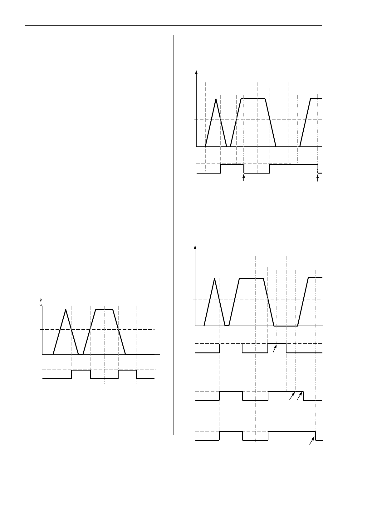
Operations Manual Series 3L
34
9.2 Behavior of Alarms After a Power
P
Alarm
Power
Power Powe
Alarm
PV
Alarm
Power
Power
Power
Alarm
Ack
Ack
Ack
Ack
Note: The alarm will only cancel when the alarm
PV
Alarm
Power
Power
Power
Alarm
Ack
Ack 2
Ack
Ack 4
Ack 2 - alarm
Ack 3 - alarm output
Ack 4 - alarm output
Alarm
Cycle
The response of an alarm after a power cycle depends
upon the latching type, whether it has been configured
to be a blocking alarm, it's state and the acknowledge
status of the alarm.
The response of active alarms after a power cycle is as
follows:
For a non-latching alarm or an event alarm blocking will
be re-instated, if configured. If bl oc king is not
configured the active alarm will remain active. If the
alarm condition has gone safe during the down time the
alarm will return inactive.
For an auto-latching alarm blocking will be re-instated, if
configured, only if the alarm had been acknowledged
prior to the power cycle. If blockin g i s not configured or
the alarm had not been acknowledged the active alarm
will remain active. If the alarm condi tion has gone safe
during the downtime the alarm will return inactive if it
had been acknowledged prior to t he power cycle else it
will return safe but not ac knowledged. If the alarm was
safe but not acknowledged prior to the power cycle the
alarm will return safe but not acknowledged.
For a manual-latching alarm blocki ng will not be reinstated and the active alarm will rem ai n active. If the
alarm condition has gone safe during the downtime the
alarm will return safe but not acknowledged. If the
alarm was safe but not acknowledged pr ior to the power
cycle the alarm will return safe but not acknowledged.
The following examples show grap hically the behaviour
under different conditions:-
9.2.1 Example 1
Alarm configured as Absolute Low; Blocking: No
Latching
SP
ON
Alarm
OFF
on
r
9.2.2 Example 2
Alarm configured as Absolute Low; Blocking: Manual
Latching
on
off/on
off/on
SP
ON
Alarm
OFF
condition is no longer current AND then it is
acknowledged
9.2.3 Example 3
Alarm configured as Absolute Low; Blocking: Auto
Latching
on
off/on
off/on
1
3
SP
ON
Alarm
OFF
output remains
in alarm
condition but
ALM indication
goes steady
remains active until the
condition causing the
alarm disappears
ON
Alarm
OFF
remains active until
acknowledged
Page 35

Series 3L Indicators
35
9.3 Alarm Parameters
ALARM L IST
‘ALARM’
Name
Scrolling Display
Parameter Description
Value
Default
Access
Level
A1.TYP
ALARM 1 TYPE
Selects the type of alarm
Alarm not configured
As order
Conf
Full Scale High
Full Scale Low
Rising rate of
change
Falling rate of
change
A1.---
ALARM 1
Alarm 1 threshold value.
Instrument range
L3
automatic resetting
Latching with
manual resetting
Event (no alarm
No blocking
Blocking
seconds
A1.OFS
ALARM
Applies a fixed offset to a full scale
different parts of a process.
Instrument range
L3
The above parameters are repeated for Alarm 2, A2; Alarm 3, A3; Alarm 4, A4
Four alarms are available. Parameters do not appear if the Alarm Type = None. The following table shows the
parameters to set up and configure alarms.
A1.STS ALARM 1
A1.HYS ALARM 1
A1.LAT ALARM 1
A1.BLK ALARM 1
A1.DLY DELAY TIME The alarm will not be indicated
SETPOINT
OUTPUT
HYSTERESIS
LATCHING TYPE
BLOCKING
The last three characters show the
type of alarm configured from the
above list
Indicates the status of the alarm
See description at the beginning of
this section
See description at the beginning of
this section
See description at the beginning of
this section
until the set time has elapsed
none
Hi
Lo
r.roc
F.roc
OFF
On
0 to 9999 Conf
none
Auto
Man
Evt
No
yes
0:00 to 99:59 mm:ss
0:59 = 59 seconds
99:59 = 99 minutes 59
Alarm off Read
Alarm on
Non-latching As order
Latching with
flashing beacon but
messages can be
displayed)
code
0
code
No
0:00
only
Conf
Conf
SETPOINT
OFFSET
high or full scale low alarm
setpoint. This may be useful when
used in conjunction with digital
communications, where a variable
value may be downloaded during
0
Page 36

Operations Manual Series 3L
36
9.3.1 Example: To Configure Alarm 1
Do This
The Display You
Should See
Additional Notes
Hi
215
Enter configuration level as des c ribed. Then:-
1. Press
necessary to select ‘ALARM’
2. Press to select ‘A1.TYP’
3. Press
required alarm type
as many times as
or
to select the
Alarm Type choices are:-
none Alarm not configured
Hi Full Scale High
a1.typ
Lo Full Scale Low
r.roc Rate of change rising
F.roc Rate of change falling
4. Press to select ‘A1.---‘
or
5. Press
to set the alarm
trip level
6. Press to select ‘A1 STS’
7. Press to select ‘A1 HYS’
or
8. Press
to set the
hysteresis
9. Press to select ‘A1 LAT’
or
10. Press
to select the
latching type
This is the alarm threshold setting for Alarm 1.
Characters (---) shown after the alarm number
indicate the type of alarm configured from the above
a1.hi
list.
The alarm threshold is shown in the upper display.
In this example the high alarm will be detected when
the measured value exceeds 215
This is a read only parameter which shows the status
of the alarm output
In this example the alarm will cancel when the
measured value decreases 2 units below the trip level
(e.g. at 213 units in this example)
Latching Type choices are:-
none No latching
Auto Automatic
Man Manual
Evt Event
See section 9.1 for an explanation of latching alarms
11. Press to select ‘A1 BLK’
or
12. Press
to ‘Yes’ or ‘No’
13. Repeat the above to configure alarms
2, 3 and 4 if required
14. Continue to press to set up a
delay before the alarm is indicated
Page 37

Series 3L Indicators
37
9.4 Diagnostic Alarms
Diagnostic alarms indicate a poss ible fault within the indicator or c onnec ted devices.
Display shows What it means What to do about it
E.Conf
E.CaL
E2.Er
EE.Er
E.Lin
A change made to a parameter takes a finite time
to be entered. If the power to the indicator is
turned off before the change has been entered
then this alarm will occur.
Do not turn the power off to the indicator while
ConF is flashing
Calibration error Re-instate Factory calibration
EEPROM error Return to factory for repair
Non-vol memory error Note the error and contact your supplier
Invalid input type. This refers to custom
linearisation which may not have been applied
correctly or may have been corrupted.
Enter configuration mode then return to the
required operating mode. It may be necessary to
re-enter the parameter change since it will not have
been entered in the previous configuration.
Go to the INPUT list in configuration level and set a
valid thermocouple or input type
Page 38

Operations Manual Series 3L
38
10. Recipe
Not Applicable
Page 39

Series 3L Indicators
39
11. Di gital Communications
Digital Communications (or ‘comms’ for short) allows
the indicator to communicate with a PC or a networked
computer system.
This product conforms to MODBUS RTU protocol a
full description of which can be found on
www.modbus.org.
Two ports are available both using MODBUS RTU
communication facilities:
1. a configuration port - intended to communicate
with a system to download the instrument
parameters and to perform manufactur i ng tests
and calibration
2. an optional EIA 485 port on terminals HD, HE and
HF - intended for field communicati ons using, for
example, a PC running a SCADA package.
The two interfaces cannot operate at the same time.
Each parameter has its own unique ModB us address.
A list of these is given at the end of this sect ion.
11.1 Digital Communications Wiring
11.1.1 EIA 485
To use EIA 485, buffer the EIA 232 port of the PC with
a suitable EIA 232/RS485 converter. The use of an
EIA 485 board built into the computer is not
recommended since this board may not be isolated,
which may cause noise problems, and the RX
terminals may not be biased correctly for this
application.
To construct a cable for EIA 485 operati on use a
screened cable with one (EIA 485) twiste d pair plus a
separate core for common. Althoug h common or
screen connections are not necessary, their use will
significantly improve noise immunity.
The terminals used for EIA 485 digital communications
are listed in the table below.
Standard
Cable
Colour
White Receive,
Red Transmit,
Green Common HD Common
Screen Ground
PC Function * Instrument
RX+
TX+
Terminal
HF (B) or
(B+)
HE (A) or
(A+)
Instrument
Function
Transmit, TX
Receive, RX
• These are the functions normally assigned to
socket pins. Please check your PC manual to
confirm.
See section 1.11 for wiring diagrams .
Page 40

Operations Manual Series 3L
40
11.2 Digital Communications Parameters
DIGITAL COMMUNICATIONS LIST ‘comms’
The following table shows the param eters available.
Name Scrolling
Display
ID MODULE
IDENTITY
ADDR ADDRESS Communications
BAUD BAUD RATE Communications
PRTY PARITY Communications
DELAY RX/TX DELAY
TIME
RETRN TRANSMITTED
PARAMETER
REG.AD DESTINATION
ADDRESS
Parameter
Description
Comms identity
address of the
instrument
baud rate
parity
To insert a delay
between Rx and Tx
to ensure that drivers
have sufficient time to
switch over.
Master
communications
broadcast parameter.
See section 11.2.1.
Parameter added in
the Slave address to
which the master
communications
value will be written
See section
11.5.
Value Default Access
none
r232
r485
1 to 254
1200
2400
4800
9600
19.20
none
Even
Odd
Off
On
none
PV
0 to 9999
No module fitted As order
EIA 232 Modbus interface
EIA 485 Modbus interface
1200
2400
4800
9600
19,200
No parity
Even parity
Odd parity
No delay
Fixed delay applied
None
Process Variable
code
1
9600
none
none
0
Level
Conf
L3 R/O
L3
Conf
L3 R/O
Conf
L3 R/O
Conf
L3 R/O
Page 41

Series 3L Indicators
41
11.2.1 Broadcast Communications
!
Series
Slave 1 Slave 2 Slave
Series 3L
B
A
Slave 1
B A Com
Com
Broadcast master communications, as a simple master,
allows the Series 3L indicator to send a single value to
any number of slave instruments. Modbus broadcast
using function code 6 (Write single v alue) must be
used. This allows the Series 3L to link with other
products, without the need for a supervisory PC, to
create a small system solution. The f acility provides a
simple and precise alternative t o anal ogue
retransmission.
The retransmitted parameter is P r ocess Variable. The
indicator will cease broadcast when it receives a valid
request from a Modbus master.
Warning
When using broadcast master communications, bear in
mind that updated values are sent man y ti m es a
second. Before using this facility, check that the
instrument to which you wish to send values can accept
continuous writes. Note that the SSI Series 3L does
not accept continuous writes to the temperature
setpoint. Damage to the internal non-volatile
memory could result from the use of this function.
If in any doubt, contact the manufacturer of the
device in question for advice.
When using the 3L series indicator fitted with software
version 1.10 and greater, use the Remot e Setpoint
variable at Modbus address 26 if you need to write to a
temperature setpoint. This has no write restrictions and
may also have a local trim value applied.
11.2.2 Broadcast Master Communications
The Series 3L broadcast master can be c onnected to
up to 31 slaves if no segment repeaters are used. If
repeaters are used to provide additional segments, 32
slaves are permitted in each new segment . The master
is configured by setting the ‘RE TRAN’ parameter to
PV.
Once the function has been enabled, t he instrument will
send this value out over the communications link every
control cycle (250ms).
Notes:-
1. The parameter being broadca s t must be set to the
same decimal point resolution in both master and
slave instruments.
2. If any Modbus master, is connected to the port on
which the broadcast master is enabled, then the
broadcast is temporarily inhibi ted. It will restart
approximately 30 seconds after t he m aster is
removed.
3L
Master
31
11.2.3 Wiring Connecti ons
The Digital Communications module for use as a
master or slave uses terminals HD to H F.
EIA485 2-wire Connections
Connect A in the master to A of the slave
Connect B in the master to B of the slave
This is shown diagrammatically below
Master
EIA485
EIA485
Page 42

Operations Manual Series 3L
42
11.3 Example: To Set Up Instrument
Do This
Display View
Additional Notes
Scrolling display
FP Value
Integer Representation
Address
This can be done in operator level 3:-
1. Press
many times as
necessary to
select ‘COMMS
LIST’
2. Press to
scroll to ‘ID
3. Press
to select
EIA485 comms
4. Press to
scroll to
‘ADDR’
5. Press
to select
the address for
the particular
indicator
as
or
or
‘comms list’
Scrolling display
‘id’
Up to 254 can be
chosen but note
that no more than
33 instruments
should be
connected to a
single
EIA485 link.
Scrolling display
‘address’
11.4 DATA ENCODING
Modbus data is normally encoded into a 16 bit signed
integer representation.
Integer format data, including any value without a
decimal point or represented by a text ual value (for
example ‘off’, or ‘on’), is sent as a simple integer value.
For floating point data, the value is represented as a
‘scaled integer’, in which the value is sent as an integer
which gives the result of the value multiplied by 10 to
the power of the decimal resolution for that value. This
is easiest to understand by refer ence to examples:
FP Value Integer Representation
9. 9
-1.0 10
123.5 1235
9.99 999
It may be necessary for the Modbus master to insert or
remove a decimal point when using these values.
Page 43

Series 3L Indicators
43
11.5 Parameter Modbus Addresses
Parameter
Parameter Name
Modbus
(Decimal)
PV.IN
PV (Temperature) Input Value (see
1
RNG.LO
Input Range Low Limit
11
A1.---
Alarm 1 Threshold
13
A2.---
Alarm 2 Threshold
14 Cal offset 4
26
zone.
A1.HYS
Alarm 1 Hysteresis
47 Cal point 4
66 Cal point 3
67
A3.HYS
Alarm 3 Hysteresis
69
A4.HYS
Alarm 4 Hysteresis
71
StAt
Instrument Status. This is a bitmap:
In each case, a setting of 1 signifies
‘Active’, 0 signifies ‘Inactive’.
75
A3.---
Alarm 3 Threshold
81
A4.---
Alarm 4 Threshold
82
FILT.T
Input Filter Time
101
only
-
Instrument version number. Should
107
-
Instrument type code.
122
HIGH
Peak high
126
LOW
Peak low
127
PV.OFS
PV Offset
141
C.Adj
Calibration Adjust
146
IM
Instrument mode
inactive
199
COLOR
Colour change
Green normal/Red on alarm –
200
MV.IN
Input value in millivolts
202
allowing the instrument to control to
sensor break alarm will be triggered
turn sensor break off.
CJC.IN
CJC Temperature
215
TARE
Tare enable
223
SBR
Sensor Break Status (0 = Off, 1 =
258
NEW.AL
New Alarm Status (0 = Off, 1 =
Active)
260
Alarm latch status
261
Ac.All
Acknowledge all alarms (1 =
274
A1.STS
Alarm 1 Status (0 = Off, 1 = Active)
294
A3.STS
Alarm 3 Status (0 = Off, 1 = Active)
296
A4.STS
Alarm 4 Status (0 = Off, 1 = Active)
297 Alarm 1 inhibit
298
Alarm 3 inhibit
300 Alarm 4 inhibit
301
REC.NO
Recipe to Recall
313
Lev2.P
Level 2 Code
515
UNITS
Display Units
4 – Percent
516
Conf.P
Config Code
518
Cold
If set to 1 instrument will reset to
519
DEC.P
Decimal Point Position
2 – XX.XX
525
0 – Absolute Alarm Outputs Active
Mnemonic
also Modbus address 203 which
allows writes over Modbus to this
variable).
RNG.HI Input Range High Limit 12
LOC.t Local Trim – added to the remote
setpoint to compensate for local
temperature variations in a control
A2.HYS Alarm 2 Hysteresis 68
Address
27
0 – Operating mode - all algorithms
and I/O are active
1 – Standby - control outputs are off
2 – Config Mode - all outputs are
Green –
Red –
PV.CM
204
Comms PV Value. This may be
used to write to the Process
Variable (temperature) parameter
over Modbus when a linearisation
type of ‘Comms’ is selected,
externally derived values.
If sensor break is turned on, it is
necessary to write to this variable
once every 5 seconds. Otherwise a
as a failsafe. If this is not required,
203
Di.IP
Home
B0 – Alarm 1 Status
B1 – Alarm 2 Status
B2 – Alarm 3 Status
B3 – Alarm 4 Status
B5 – Sensor Break Status
B10 – PV Overrange (by > 5% of
span)
B12 – New Alarm Status
Digital Inputs Status. This is a
bitmap:
B0 – Logic input 1A
B1 – Logic input LA
B2 – Logic input LB
B7 – Power has failed since last
alarm acknowledge
A value of 1 signifies the input is
closed, otherwise it is zero. Values
are undefined if options are not
fitted or not configured as inputs.
Home Display.
0 – Standard PV display
4 – PV and Alarm 1 setpoint
6 – PV only
7 – PV and Alarm 1 setpoint read
87
106
Off –
On –
Fail -
Active)
Acknowledge
A2.STS Alarm 2 Status (0 = Off, 1 = Active) 295
Alarm 2 inhibit 299
STORE Recipe to Save 314
0 – Degrees C
1 – Degrees F
2 – Kelvin
3 – None
Lev3.P Level 3 Code 517
be read as a hexadecimal number,
for example a value of 0111 hex is
instrument V1.11
- Static message 108
ADDR Instrument Comms Address 131
STBY.T Standby Type
factory defaults on next reset or
power cycle.
0 – XXXX.
1 – XXX.X
530
Page 44

Operations Manual Series 3L
44
– others off
1 – All outputs inactive
uCAL
User Calibration Enable
533
A1.TYP
Alarm 1 Type
5 – Deviation Band
536
A2.TYP
Alarm 2 Type
(as Alarm 1 Type)
537 A3.TYP
Alarm 3 Type
(as Alarm 1 Type)
538 A4.TYP
Alarm 4 Type
(as Alarm 1 Type)
539
2 – Latch – Manual Reset
A2.LAT
Alarm 2 Latching Mode
(as Alarm 1 Latching Mode)
541 A3.LAT
Alarm 3 Latching Mode
(as Alarm 1 Latching Mode)
542 A4.LAT
Alarm 4 Latching Mode
(as Alarm 1 Latching Mode)
543
OFF, 1 = BLOCK)
A4.BLK
Alarm Blocking Mode Enable (0 =
547
Di.OP
Digital Outputs Status. This is a
when writing to this variable.
551
Alarm 1 delay
552
Alarm 4 delay
555 Alarm 1 offset
556 Alarm 2 offset
557
Alarm 4 offset
559
OFS.HI
Adjust High Offset
560
OFS.LO
Adjust Low Offset
561
PNT.LO
Adjust Low Point
563
SB.TYP
Sensor Break Type
578
2 – Latching Sensor Break
SB.DIR
Sensor break direction
Up –
579
Id
Customer ID – May be set to any
instrument itself.
629
PHASE
Calibration Phase
768
but are status returns only
Allows instrument to be locked via a
IN.TYP
Input Sensor Type
11 – Custom Input (Downloadable)
12290
2- 50 Degrees C
mV.HI
Linear Input High
12306
mV.LO
Linear Input Low
12307
L.TYPE
Logic Input A channel hardware
1 – Logic Inputs
12352
45 – Timer Run
Down –
0 – Off
1 –Absolute High
2 – Absolute Low
3 – Deviation High
4 – Deviation Low
value between 0-9999 for
identification of instruments in
applications. Not used by the
A1.LAT
Alarm 1 Latching Mode
0 – No latching
1 – Latch - Automatic Reset
A1.BLK Alarm Blocking Mode Enable (0 =
A2.BLK Alarm Blocking Mode Enable (0 =
OFF, 1 = BLOCK)
A3.BLK Alarm Blocking Mode Enable (0 =
OFF, 1 = BLOCK)
OFF, 1 = BLOCK)
bitmap:
B0 – Output 1A
B1 – (not used)
B2 – Output 3A
B3 – Output 4/AA
It is possible to write to this status
word to use the digital outputs in a
telemetry output mode. Only
outputs whose function is set to
‘none’ are affected, and the setting
of any bits in the Digital Output
Status word will not affect outputs
used for heat (for example) or other
functions. Thus it is not necessary
to mask in the settings of these bits
540
544
545
546
GO
K.LOC
0 – None
1 – 0 mv
2 – 50 mv
3 – 150 Ohm
4 – 400 Ohm
5 – CJC
6 – CT 0 mA
7 – CT 70 mA
8 – Factory Defaults
Calibration Start
0 – No
1 – Yes (start cal)
2 – Cal Busy
3 – Cal Pass
4 – Cal Fail
Note values 2-4 cannot be written
key/digital input
0 - unlocked,
1 – all keys locked
2 – Edit keys (raise and lower)
disabled
3 – Mode key disabled
4 – Manual mode disabled
5 – Enter standby mode when
Mode combination pressed
6 – Timer keys disabled
0 – J Type Thermocouple
1 – K Type Thermocouple
2 – L Type Thermocouple
3 – R Type Thermocouple
4 – B Type Thermocouple
5 – N Type Thermocouple
6 – T Type Thermocouple
7 – S Type Thermocouple
8 – RTD
9 – millivolt
10 – Comms Input (see Modbus
address 203)
769
1104
Alarm 2 delay 553
Alarm 3 delay 554
CJ.TYP
CJC Type
0 – Auto
1 – 0 Degrees C
12291
Alarm 3 offset 558
PNT.HI Adjust High Point 562
L.D.IN
0 – No Sensor Break
1 – Non-Latching Sensor Break
type
0 – None
Logic input A function
40 – None
41 – Acknowledge all alarms
42 – Select SP1/2
43 – Lock All Keys
44 – Timer Reset
12353
Page 45

Series 3L Indicators
45
46 – Timer Run/Reset
49 – Standby Select
L.SENS
Configures the polarity of the logic
12361
L.TYPE
Logic Input B channel hardware
1 – Logic Inputs
12362
Inverted)
2 – RS232
BAUD
Baud Rate
4 – 1200
12548
2 – Odd
DELAY
RX/TX Delay – (0 = no delay, 1 =
adaptors are used.
12550
4 – Error
units).
Cal 3 offset
12558
Cal 4 offset
12559
1.FUNC
I/O Channel Function
0 – None (or Telemetry Output)
12674
1 – Digital Output
1.SRC.A
IO Channel 1 Source A
9 – Sensor Break Alarm
12677
As IO Channel 1 Source A (Modbus
address 12678)
As IO Channel 1 Source A (Modbus
address 12678)
1.SRC.D
IO Channel 1 Source D
As IO Channel 1 Source A (Modbus
address 12678)
12680
1.SENS
Configures the polarity of the input
Inverted)
12681
IO1 high
12682
IO1 telemetry
12683
3.SRC.A
Output 3 source A
As IO Channel 1 Source A (Modbus
address 12678)
12806
3.SRC.B
Output 3 source B
As IO Channel 1 Source A (Modbus
address 12678)
12807
3.SRC.C
Output 3 source C
As IO Channel 1 Source A (Modbus
address 12678)
12808
3.SRC.D
Output 3 source D
As IO Channel 1 Source A (Modbus
address 12678)
12809
3.SENS
Output 3 Polarity (0 = Normal, 1 =
Inverted)
12810
Output 3 telemetry
12812
4.TYPE
Output AA Type
13056
1 – Digital Output
As IO Channel 1 Source A (Modbus
address 12678)
As IO Channel 1 Source A (Modbus
address 12678)
As IO Channel 1 Source A (Modbus
address 12678)
4.SRC.D
Output AA source D
As IO Channel 1 Source A (Modbus
address 12678)
13065
4.SENS
Output AA sense (0 = Normal, 1 =
Inverted)
13066
47 – Timer Hold
48 – Auto/Manual Select
(LB)
L.D.IN
(LB)
L.SENS
(LB)
ID
input channel A (0 = Normal, 1 =
Inverted)
type
0 – None
Logic input B function)
40 – None
41 – Acknowledge all alarms
42 – Select SP1/2
43 – Lock All Keys
44 – Timer Reset
45 – Timer Run
46 – Timer Run/Reset
47 – Timer Hold
48 – Auto/Manual Select
49 – Standby Select
Configures the polarity of the logic
input channel B (0 = Normal, 1 =
Comms Module Type
0 – None
1 – RS485
0 – 9600
1 – 19200
2 – 4800
3 – 2400
12363
12377
12544
0 – None
1 – Alarm 1
2 – Alarm 2
3 – Alarm 3
4 – Alarm 4
5 – All Alarms (1-4)
6 – New Alarm
1.SRC.B IO Channel 1 Source B
1.SRC.C IO Channel 1 Source C
or output channel (0 = Normal, 1 =
3.ID
Output 3 Type
0 – None
1 – Relay
3.FUNC
Output 3 Channel function
0 – None (or Telemetry Output)
1 – Digital Output
12678
12679
12800
12803
PRTY
Parity setting
0 – None
1 – Even
delay) Select if a delay is required
between received and transmitted
comms messages. Sometimes
required when intelligent RS485
RETRN Comms Retransmission Variable
selection:
0 – Off
1 – Working Setpoint
2 – PV
3 – Output Power
REG.AD Modbus register address to
broadcast retransmission to. For
example if you wish to retransmit
the working setpoint from one
Series 3L to a group of slaves, and
receive the master working setpoint
into the slaves’ remote setpoint, set
this variable to 26 (the address of
the remote setpoint in the slave
1.ID
IO channel 1 hardware type
0 – None
1 – Relay
12549
12551
12552
12672
0 – None
1 – Relay
4.FUNC Output 4 Channel function
0 – None (or Telemetry Output)
4.SRC.A Output AA source A
4.SRC.B Output AA source B
4.SRC.C Output AA source C
13059
13062
13063
13064
Page 46

Operations Manual Series 3L
46
12. Calibration
Copper cable
mV
+
-
Indicator
VI
V-
V+
Thermocouple
Thermocouple
+
-
Indicator
VI
V-
V+
All ranges are calibrated during man ufacture to
traceable standards for every input type. When
changing ranges it is not necessary to calibrate the
indicator. Furthermore, the use of a continuous
automatic zero correction of the input ensures that the
calibration of the instrument is optimized during normal
operation.
To comply with statutory procedures such as the
Heat Treatment Specification AMS2750, the
calibration of the instrument can be verified and recalibrated if considered necessary in accordance
with the instructions given in this chapter.
For example AMS2750 states:-
"Instructions for calibration and recalibration of ‘field test
instrumentation’ and ‘control monitori ng a nd recording
instrumentation’ as defined by the NADCAP Aerospace
Material Specification for pyrometry AMS2750D clause
3.2.5 (3.2.5.3 and sub clauses) including Instruction for
the application and removal of off sets defined in clause
3.2.4”.
12.1 To Check Input Calibration
The PV Input may be configured as mV, mA,
thermocouple or platinum resistance thermometer.
12.1.1 Precautions
Before checking or starting any cal i bration procedure
the following precautions shou ld be taken:-
1. When calibrating mV inputs mak e sure that the
calibrating source output is set to less than
250mV before connecting it to the mV
terminals. If accidentally a large potential is
applied (even for less than 1 second), then at
least one hour should elapse before
commencing the calibration.
2. RTD and CJC calibration must not be carried
out without prior mV calibration.
3. A pre-wired jig built using a spare instrument
sleeve may help to speed up the calibration
procedure especially if a number of
instruments are to be calibrated.
4. Power should be turned on only after the
instrument has been inserted in the sleeve of
the pre-wired circuit. Power shou ld al so be
turned off before removing the instr ument from
its sleeve.
5. Allow at least 10 minutes for the instrument to
warm up after switch on.
12.1.2 To Check mV Input Calibration
The input may have been configured for a process input
of mV, Volts or mA and scaled in Level 3 as des cribed
in section 5. The example described in section 6.1.4
assumes that the display is set up to read 2.0 for an
input of 4.000mV and 500.0 for an input of 20.000mV.
To check this scaling, connect a milli-volt source,
traceable to national standards, to terminals V+ and Vusing copper cable as shown in the diagram below.
Source
Ensure that no offsets (see sections 6.1.3 and 12.2)
have been set in the indicator.
Set the mV source to 4.000mV. Check t he display
reads 2.0 +0.25% + 1LSD (least significant digit).
Set the mV source to 20.000mV. Check t he display
reads 500.0 +0.25% + 1LSD.
12.1.3 To Check Thermocouple Input Calibration
Connect a milli-volt source, traceable to national
standards, to terminals V+ and V- as shown in the
diagram below. The mV source must be capable of
simulating the thermocouple cold junction temperature.
It must be connected to the instrument using the correct
type of thermocouple compensating c able for the
thermocouple in use.
Compensating cable
Set the mV source to the same thermocouple type as
that configured in the indicator.
Adjust the mV source to the minimum range. For a type
J thermocouple, for example, the minimum range is 210OC. However, if it has been restricted using the
Range Low parameter then set the mV source to this
limit. Check that the reading on the display is within
+0.25% of minimum range + 1LSD.
Adjust the mV source for to the maximum range. For a
type J thermocouple, for example, the maximum range
is 1200OC. However, if it has been restricted using the
Range High parameter then set the m V source to this
limit. Check that the reading on the display is within
+0.25% of maximum range + 1LSD.
Intermediate points may be similarly checked if
required.
simulator set to
T/C type
Page 47

Series 3L Indicators
47
12.1.4 To Check RTD Input Calibration
INPUT
Cal
Do This
Display View
Notes
Electrical
Display
High offset
Factory
Low offset
Electrical
Display
High offset
Factory
Low offset
Output Hi
Output Lo
Input Hi
Input Lo
Cal Point 5
Cal Point 4
Cal Point 3
Cal Point 2
Cal Point 1
Matched impedance copper
Decade
Indicator
VI
V-
V+
Connect a decade box with total resist ance lower than
1K and resolution to two decimal places in place of the
RTD as indicated on the connection diagram below
before the instrument is powered up. If at any
instant the instrument was powere d up without this
connection then at least 10 minutes must elapse from
the time of restoring this connect ion before RTD
calibration check can take place.
leads
Box
The RTD range of the instrument is -200 to 850OC. It
is, however, unlikely that it will be necessary to check
the instrument over this full range.
Set the resistance of the decade box to the minimum
range. For example 0
calibration is within +0.25% of 0
Set the resistance of the decade box to the maximum
range. For example 200
calibration is within +0.25% of 200
O
C = 100.00Ω. Check the
O
+ 1LSD.
O
C = 175.86Ω. Check the
O
+ 1LSD.
12.2 Offsets
The process value can be offset to tak e i nto account
known errors within the process. The offset can be
applied to any Input Type (mV, V, mA, thermocouple or
RTD).
A single offset can be applied - the proc edure is carried
out in the
6.1.3.
It is also possible to adjust the low and high points as a
five point offset. This can only be done in Level 3 in the
‘
12.2.1 Five Point Offset
A five point offset may be used to compensate for
transducer or measurement non-linearities. The
diagram shows an example of the type of discontinuity
which might occur in a system.
In this case adjust each point in tur n for the VALUE
WHICH THE INDICATOR SHOULD READ. For
example if the value at point 1 should be 1. 2345 then
set Pnt.1 to this value. The following example shows
how to do this.
list and has been described in section
’ list and is described below.
1. Select Level 3 as
described in Chapter 2.
Then press
to
Scrolling
message
calibration
list
select ‘CAL’
2. Press to scroll
to ‘u.cal’
3. Press
or
to ‘pnt.1’
4. Press to scroll
to ‘C.Adj’
5. Press
or
Scrolling
message
user
calibration
To revert to
the original
values,
select
rSet
Note:- this is
not an offset
value
to the correct value
6. Repeat the above
for points 1 to 5
In some cases it will not be necessar y t o adjust all 5
points. For example, a low and high adjustment may be
all that is necessary as shown in the following
diagrams.
Reading
(e.g. 6)
calibration
(e.g. 1)
Input
Reading
calibration
Input
In this case set Pnt.1 to the required low point value.
For the high point value you may select any point
Pnt.2 to Pnt.5. The instrument applies a straight li ne
between the two points.
Note:The calibration points must be chosen consecutively –
the five point calibration will not work if a higher point is
inserted between other points.
Page 48

Operations Manual Series 3L
48
12.3 Input Calibration
Do This
Display View
Additional Notes
Scrolling display
none
phase
Scrolling display
Do This
Display View
Additional
Notes
Copper cable
50 mV
+
-
Indicator
VI
V-
V+
Thermocouple
Thermocouple
+
-
Controller
VI
V-
V+
If the calibration is not within the specified accuracy
follow the procedures in this sect ion:
In Series 3L series instruments, inputs which can be
calibrated are:
• mV Input. This is a linear 80mV range calibrated
at two fixed points. This should always be done
before calibrating either thermocouple or resistance
thermometer inputs. mA range calibration is
included in the mV range.
• Thermocouple calibration involves calibrating the
temperature offset of the CJC sensor o nly. Other
aspects of thermocouple calibration are also
included in mV calibration.
• Resistance Thermo meter. This is also carried out
at two fixed points - 150Ω and 400Ω.
12.3.1 To Calibrate mV Range
Calibration of the mV range is carried out using a 50
milli-volt source, connected as shown in the diagram
below. mA calibration is included in this procedure.
For best results 0mV should be calibrat ed by
disconnecting the copper wires from the mV source and
short circuiting the input to the indicator
Select Conf Level as described in Chapter 2, set the
indicator input to mV range, then:-
Source
7. Set mV source for 50mV
8. Press to
select ‘PHASE’
9. Press
to choose ‘50’
10. Repeat 5 & 6
above
12.3.2 To Calibrate Thermocouple Ranges
Thermocouples are calibrated, firstly, by following the
previous procedure for the mV ranges, then calibrating
the CJC.
This can be carried out using an external CJC reference
source such as an ice bath or using a thermocouple mV
source. Replace the copper cable shown in the
diagram below with the appropriate compensating cable
for the thermocouple in use.
Set the mV source to internal compensat ion for the
thermocouple in use and set the output for 0mV.
As it calibrates the display will show
busy then pass, assuming a
successful calibration.
If it is not successful then ‘
be displayed. This may be due to
incorrect input mV
The indicator
calibrates to the
high point in the
same way as the
or
Compensating
cable
low point above
simulator set to
T/C type and 0
FAIL’ will
o
C
Then:-
1. From any
display press
as many times as
necessary until the
‘CAL’ page header
is displayed.
2. Press to
select ‘PHASE’
3. Set mV source for 0mV
4. Press
or
to choose ‘0’
5. Press to
select ‘GO’
6. Press
or
to choose
‘YES’
‘CALIBRATION
LIST’
1. From the mV
calibration, press
‘CALIBRATION
phase’
‘CJC’
2. Press to
select ‘GO’
3. Press
Scrolling display
CALIBRATION
‘
start’
The indicator
automatically
calibrates to the
injected input mV.
or
to select
or
to choose ‘YES’
The indicator
automatically
calibrates to
the CJC input
at 0mV.
As it does this
the display will
show
then
assuming a
successful
calibration.
If it is not
successful
then ‘
be displayed.
This may be
due to an
incorrect input
mV
busy
pass,
FAIL’ will
Page 49

Series 3L Indicators
49
Do This
Display View
Notes
3. Set the decade box for 150.00Ω
Matched
Decade Box
Controller
VI
V-
V+
12.3.3 To Calibrate RTD Ranges
The two points at which the RTD range is c alibrated are
150.00Ω and 400.00Ω.
Before starting RTD calibration:
• A decade box with total resistance lower than 1K
must be connected in place of the RTD as
indicated on the connection diagram below before
the instrument is powered up. If at any instant
the instrument was powered up without this
connection then at least 10 minutes must elapse
from the time of restoring this connection before
RTD calibration can take place.
• The instrument should be powered up for at least
10 minutes.
Before using or verifying RTD calibration:
• The mV range must be calibrated first .
impedance
copper leads
1. From any display
press
times as necessary until
the ‘CAL’ page header
is displayed.
2. Press to select
‘PHASE’
4. Press
to choose ‘150r’’
5. Press to select
‘GO’
6. Press
to choose ‘YES’
The indicator automatically calibrates to the injected
150.00Ω input.
As it does this the display will show
assuming a successful calibration.
If it is not successful then ‘
may be due to an incorrect input resistance
7. Set the decade box for 400.00Ω
as many
or
or
busy then pass,
FAIL’ will be displayed. This
Scrolling
display
‘
CALIBRA
TION
LIST’
Scrolling
display
‘
CALIBRA
TION
phase’
Scrolling
display
‘
CALIBRA
TION
start’
8. Press
or
to choose ‘400r’’
9. Repeat 5 and 6
above to calibrate the
high point
The indicator will again automatically calibrate to the
injected 400.00Ω input.
If it is not successful then ‘
FAIL’ will be displayed
Page 50

Operations Manual Series 3L
50
CALI BRAT ION PARAMETER LIS T
‘cAL’
PHASE
CALIBRATION
To calibrate low
Return to factory settings
Factory
Not selected
Conf only
Select mV i/p low calibration point
Select V i/p low calibration point
Select PRT i/p high cal point
Select CJC calibration
Initial state
Start
Calibrating
Calibration successful
Start auto calibration
12.4 Calibration Parameters
The following table lists the parameters available in the Calibration Lis t.
Name Scrolling
Display
UCAL USER
CALIBRATION
PHASE
GO CALIBRATION
START
Parameter
Description
To calibrate the 5
point linerization
table.
and high offset
To start the
calibration
sequence
Value Default Access
IDLE
PnT.1
PnT.2
PnT.3
PnT.4
PnT.5
rset
Fact
none
0
50
0V
150r
400r
CJC
NO
Yes
Busy
Pass
faiL
YES
Lo
Hi
pass
faiL
Select mV i/p high calibration point
Select PRT i/p low cal point
Calibration unsuccessful
These parameters automatically
appear as the calibration takes
place.
Fact
none
NO
Level
L3 only
Conf
Page 51

Series 3L Indicators
51
13. T ECHNICAL SPECIFICATION
Temperature limits
Operation: 0 to 55°C (32 to 131°F),
Storage: -10 to 70°C (14 to 158°F)
Humidity limits
Operation: RH: 5 to 90% non-condensing
Storage: RH: 5 to 90% non-condensing
Shock
BS EN61010
Vibration
2g peak, 10 to 150Hz
Altitude
<2000 metres
Electromagnetic
(EMC)
BS EN61326
Installation
category II
The rated impulse voltage for equipment
on nominal 230V supply is 2500V
Pollution degree 2
Normally only non conductive pollution
condensation shall be expected.
Physical
Series 3L
Panel mounting
1/4 DIN
Weight grams
420
Panel cut-out
dimensions mm
Type
LCD TN with backlight
Main PV display
Series 3L
green
Lower display
Series 3L
100 to 240Vac, -15%, +10%
max 8W
CE, cUL listed (file ES7766), Gost, FM,
Sample time:
9hz (110ms)
Isolation:
264Vac double isolation from the PSU
Excitation:
10Vdc +7%
Sensitivity:
1.4 to 4mV/V
Input span:
-27% to +127% of full scale (approx. –
General
Panel sealing IP 65, Nema 4X
Atmospheres Not suitable for use above 2000m or in
compatibility
Electrical safety BS EN61010 Installation cat. II; Pollution
Dimensions mm
Operator interface
4 digits
Status beacon Units, outputs, alarms, active setpoint
Power requirements
Approvals
Transmitter PSU
Isolation 264Vac double insulated
Output Voltage 24Vdc, 20mA
Communications: serial communications option
Protocol Modbus RTU slave
Isolation 264Vac double insulated
explosive or corrosive atmospheres.
degree 2
occurs. Occasionally, however, a
temporary conductivity caused by
96W x 96H x
90D
92W x 92H
5 character
starburst,
green
48 to 62Hz, max 8W
24Vac, -15%, +10%
24Vdc, -15%, +20%, +5% ripple voltage,
EN14597TW approval number TW1222.
Modbus RTU Master broadcast (1
parameter)
Transmission
EIA485 2-wire
standard
Transmission
standard
EIA485 2-wire
Process Variable Input
Calibration accuracy <+0.25% of reading +1LSD
(1)
Sample rate 9Hz (110mS)
Isolation 264Vac double insulated from the PSU
and communications
Resolution (µV) < 0.5µV with 1.6s filter (mV range)
< 0.25µV with 1.6s filter (Volts range)
Resolution (effective
>17 bits
bits)
Linearisation
<0.1% of reading
accuracy
Drift with
<50ppm (typical) <100ppm (worst case)
temperature
Common mode
48 - 62 Hz, >-120db
rejection
Series mode
48 - 62 Hz, >-93db
rejection
Input impedance
Cold junction
compensation
External cold
100MΩ (200KΩ on volts range C)
>30 to 1 rejection of ambient
temperature
Reference of 0
O
C
junction
Cold junction
<+1oC at 25oC ambient
accuracy
Linear (process)
input range
Thermocouple Types K, J, N, R, S, B, L, T, C, custom
-10 to 80mV, 0 to 10V with external
potential divider module 100KΩ/806Ω
download
(2)
RTD Type 3-wire, Pt100 DIN43760
Bulb current 0.2mA
Lead compensation No error for 22 ohms in all 3 leads
Input filter Off to 100 seconds
Zero offset User adjustable over the full display
range
User calibration 2-point gain & offset
Notes
(1) Calibration accuracy quoted over full ambient operating
range and for all input linearisation types.
(2) Contact SSI for details of availability of custom downloads for
alternative sensors.
and communications
Page 52

Operations Manual Series 3L
52
10mV to +5mV):
Zero balance: + 25% of full scale
Tare:
+ 25% of full scale
Resolution (mV):
0.3mV/V(typical) with 1.6s filter
Resolution
(effective bits):
14.3 bits
temperature:
Common mode
rejection:
48-62Hz, >-120db
Series rejection:
48-62Hz, >-60db
AA relay
Type
Form C changeover
Rating
Min: 100mA @ 12Vdc,
Max: 2A @ 264Vac resistive
Digital input A/B
Contact closure
Open >600Ω Closed <300Ω
Input current
<13mA
Isolation
None from PV or system
Functions
Includes alarm acknowledge, keylock,
zero, peak reset
Type
OP1, OP3
Form A (normally open)
AA
Form C changeover
Rating
Min: 100mA @ 12Vdc, Max: 2A @
Functions
Alarms or events
FM
Drift with
<100ppm/°C of full scale
Alarm 1
configuration:
Absolute hi or lo, de-energized in alarm
Latching output on Form C (AA) Relay
All alarms active on sensor break and
power fail
Alarm setpoint: Adjustment protection via password
Configuration
security
FM option prevents reconfiguration of alarm
config
Input filter: Off to 100s
Functions Alarms or events
264Vac double insulated from PSU and
communications
alarm inhibit, freeze display, tare, auto
Relay output channels
264Vac resistive
Software features
Alarms
Number 4
Type Absolute high and low, rate of change
(rising or falling)
Latching Auto or manual latching, non-latching, event
only
Output
assignment
Up to four conditions can be assigned to
one output
Custom messages
Number 15 scrolling text messages
Number of
127 characters per message max
characters
Languages English, German, French, Spanish, Italian
Selection Active on any parameter status using
conditional command
Recipes
Number 5 with 19 parameters
Selection HMI interface, communications or dig. IO
Other features
Scrolling text Parameter help, cus tom messages
Display filter Off to zero last 2 digits
Peak monitor Stores high and low values
Page 53

Series 3L Indicators
53
14. Par am et er Index
Parameter
Parameter Name
Parameter list &
Section
1.SRC.A
I/O 1 SOURCE A
Output 1 List section 7.1
3.SRC.A
I/O 3 SOURCE A
Output 1 List section 7.2
Parameter
Parameter Name
Parameter list &
Section
HOME
Access List section 6.5
INP.LO
LINEAR INPUT LOW
Input List section 6.1
This is a list of parameters in alpha/numeric order to help
locate the section in which they are applicable.
1.FUNC I/O 1 FUNCTION Output 1 List section 7.1
1.ID I/O 1 TYPE Output 1 List section 7.1
1.SENS I/O 1 SENSE Output 1 List section 7.1
1.SRC.B I/O 1 SOURCE B Output 1 List section 7.1
1.SRC.C I/O 1 SOURCE C Output 1 List section 7.1
1.SRC.D I/O 1 SOURCE D Output 1 List section 7.1
3.FUNC I/O 3 FUNCTION Output 3 List section 7.2
3.ID I/O 3 TYPE Output 3 List section 7.2
3.SENS I/O 3 SENSE Output 1 List section 7.2
3.SRC.B I/O 3 SOURCE B Output 1 List section 7.2
3.SRC.C I/O 3 SOURCE C Output 1 List section 7.2
3.SRC.D I/O 3 SOURCE D Output 1 List section 7.2
4.FUNC I/O 4 FUNCTION
4.SENS I/O 4 SENSE
4.SRC.A I/O 4 SOURCE A
4.SRC.B I/O 4 SOURCE B
4.SRC.C I/O 4 SOURCE C
4.SRC.D I/O 4 SOURCE D
4.TYPE OUTPUT 4 TYPE
A1.--- ALARM 1 SETPOINT Alarm List section 9.3
A1.BLK ALARM 1 BLOCKING Alarm List section 9.3
A1.DLY DELAY TIME Alarm List section 9.3
A1.HYS
A1.LAT
A1.OFS
A1.STS ALARM 1 OUTPUT Alarm List section 9.3
A1.TYP ALARM 1 TYPE Alarm List section 9.3
ADDR ADDRESS
BAUD BAUD RATE
CJ.TYP CJC TYPE Input List section 6.1
CJC.IN CJC TEMPERATURE Input List section 6.1
COLD
CONF.P CONFIG PASSCODE Access List section 5.5
DEC.P DISPLAY POINTS Input List section 6.1
DELAY RX/TX DELAY TIME
E.CaL
ALARM 1
HYSTERESIS
ALARM 1 LATCHING
TYPE
ALARM SETPOINT
OFFSET
COLD START
ENABLE/ DISABLE
Output 4 List (AA Relay)
section 7.3
Output 4 List (AA Relay)
section 7.3
Output 4 List (AA Relay)
section 7.3
Output 4 List (AA Relay)
section 7.3
Output 4 List (AA Relay)
section 7.3
Output 4 List (AA Relay)
section 7.3
Output 4 List (AA Relay)
section 7.3
Alarm List section 9.3
Alarm List section 9.3
Alarm List section 9.3
Digital Communications List
section 11.2
Digital Communications List
section 11.2
Access List section 5.5
Digital Communications List
section 11.2
Diagnostic Alarm List
section 9.4
E.Conf
E.Lin
E2.Er
EE.Er
FILT.D DISPLAY FILTER Input List section 6.1
FILT.T FILTER TIME Input List section 6.1
GO CALIBRATION START Calibration List section 12.4
GOTO GOTO Access List section 5.5
HOME DISPLAY See
Note 1
ID CUSTOMER ID Access List section 5.5
ID MODULE IDENTITY
IN.TYP INPUT TYPE Input List section 6.1
INP.HI LINEAR INPUT HIGH Input List section 6.1
K.LOCK KEYBOARD LOCK Access List section 5.5
L.D.IN
L.SENS LOGIC INPUT SENSE Digital Input List section 8.1
L.TYPE LOGIC INPUT TYPE Digital Input List section 8.1
LEV2.P LEVEL 2 PASSCODE Access List section 5.5
LEV3.P LEVEL 3 PASSCODE Access List section 5.5
MESG
MV.IN
PASS.C FEATURE PASSCODE Access List section 5.5
PHASE CALIBRATION PHASE Calibration List section 12.4
PRTY PARITY
PV.IN PV INPUT VALUE Input List section 6.1
PV.OFS PV OFFSET Input List section 6.1
REG.AD
RETRN
RNG.HI RANGE HIGH LIMIT Input List section 6.1
RNG.LO RANGE LOW LIMIT Input List section 6.1
SB.DIR
SB.TYP SENSOR BREAK TYPE Input List section 6.1
UCAL USER CALIBRATION Calibration List section 12.4
UNITS DISPLAY UNITS Input List section 6.1
LOGIC INPUT
FUNCTION
STATIC HOME
MESSAGE
MILLIVOLT INPUT
VALUE
DESTINATION
ADDRESS
TRANSMITTED
PARAMETER
SENSOR BREAK
DIRECTION
Diagnostic Alarm List
section 9.4
Diagnostic Alarm List
section 9.4
Diagnostic Alarm List
section 9.4
Diagnostic Alarm List
section 9.4
Digital Communications List
section 11.4
Digital Input List section 8.1
Access List section 5.5
Input List section 6.1
Digital Communications List
section 11.4
Digital Communications List
section 11.2
Digital Communications List
section 11.2
Input List section 6.1
Page 54

Operations Manual Series 3L
54
15. Revision Histor y
Rev. Description Date MCO #
New First release
A Second release
B Terminals 2A and 2B deleted and 1A and 1B moved
where 2A and 2B previously were. The pr evious 1A
and 1B locations are now left blank. References to 2A
6/2/2014 2133
and 2B removed.
 Loading...