

Page 1
45.80
50
Page 2

Page 3

3
Table of contents
TANDARD DISPLAY.......................................................................................page 57
Page 4

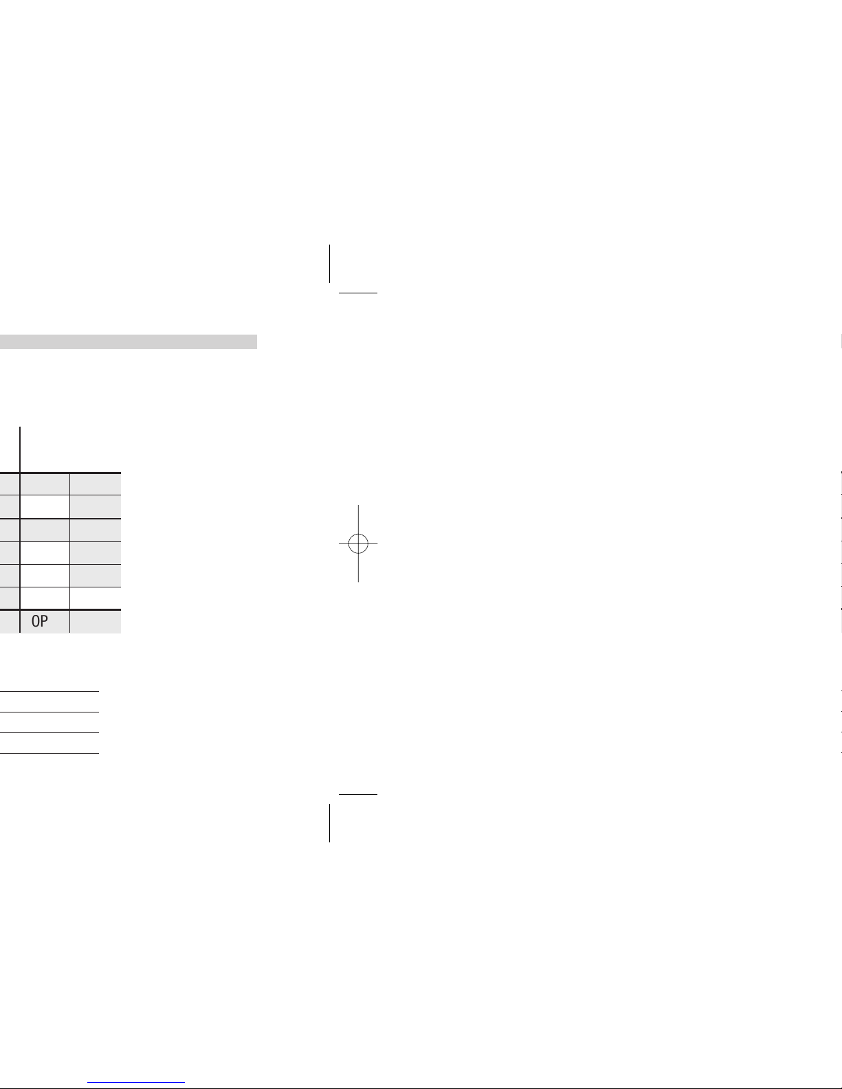
Control Alarms
Retransmission
OP1
OP2
OP3
OP4
OP5
OP6
(option)
Operating mode
2 OP5 OP1 OP2 OP3 OP4 OP6
3 OP1 OP2 OP3 OP4 OP5 OP6
4 OP1 OP5 OP2 OP3 OP4 OP6
5 OP5 OP2 OP1 OP3 OP4 OP6
1 OP1 OP2 OP3 OP4 OP5 OP6
6 OP5 OP6 OP1 OP2 OP3 OP4
7
Valve
OP1 OP2 OP3 OP4 OP5 OP6
PV/SP/MV
Fuzzy tuning
with automatic selection
One shot
Auto tuning
One shot
Natural Frequency
(opt.)
Single
action
Double
action
Page 5
5
1 - Introduction
0
––
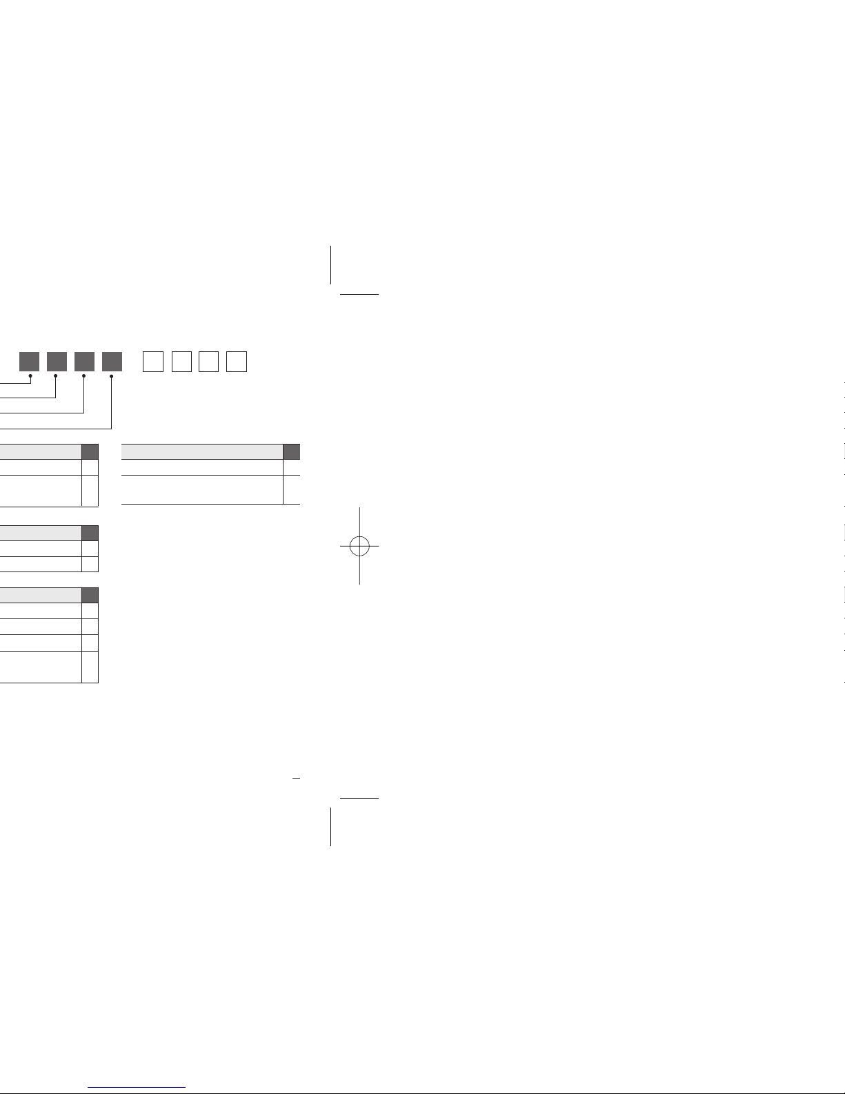
0X5 A B C D 3 0
3
5
5
1
5
0
2ndSSR drive/analog
output (OP6)
4
Options D
None
0
8
7
Page 6
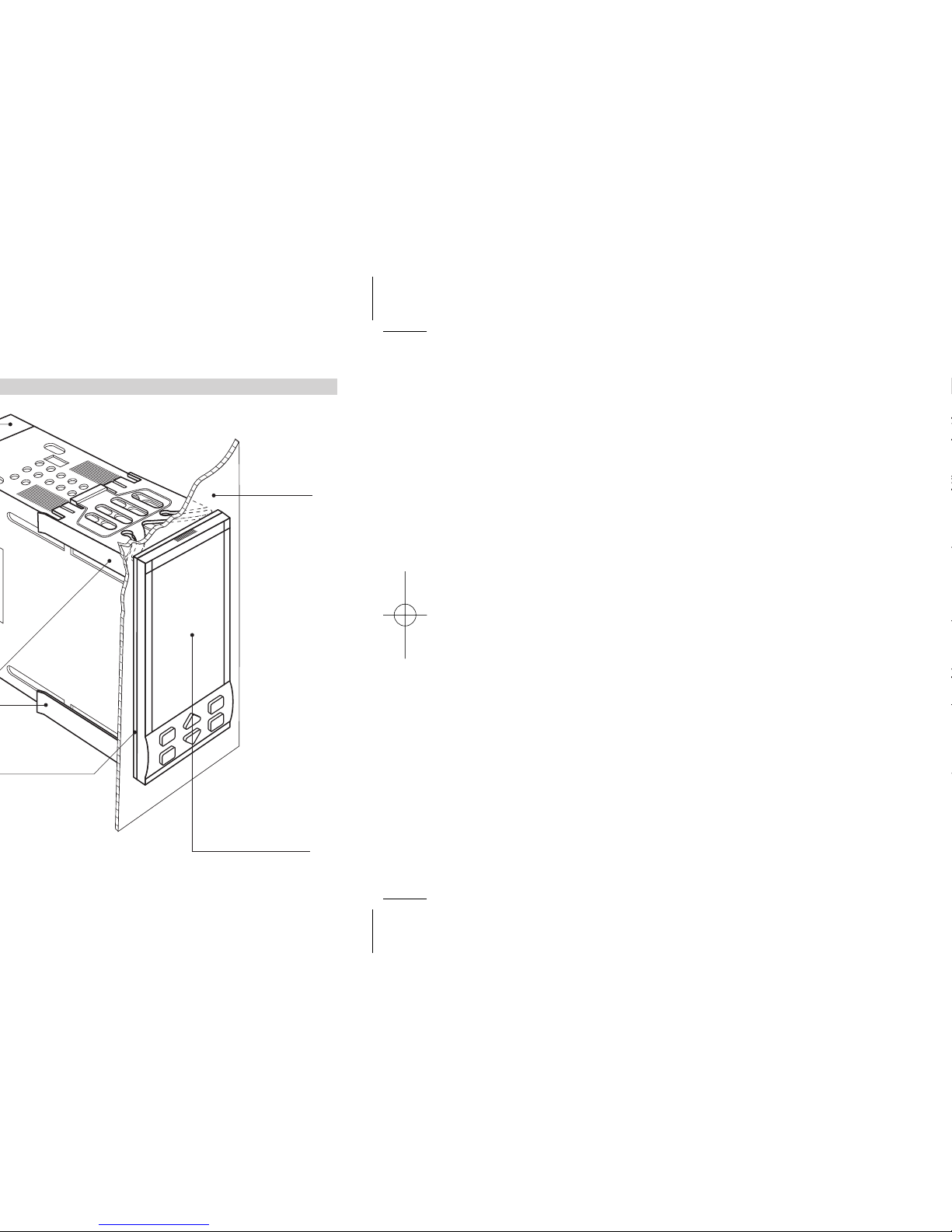
Front panel
IP65 protection
EN 650529 (IEC 529)
Panel
surface
Page 7
7
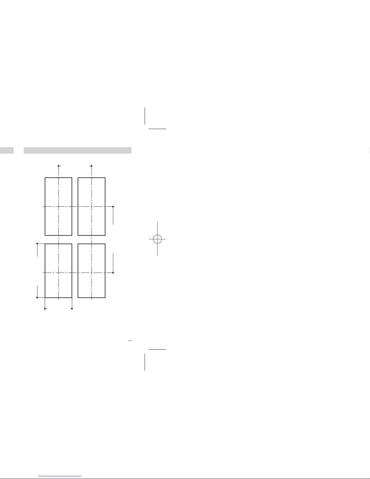
2 - Installation
65 mm min
2.56 in min
45
+0.6
mm
1.78
+0.023
in
92
+0.8
mm
3.62
+0.031
in
113 mm min
4.45 in min
Page 8

B
Use filter
Warm up
Use forced air ventilation
Use 24Vac supply version
Suggestions
Page 9
9
2 - Installation
1
2
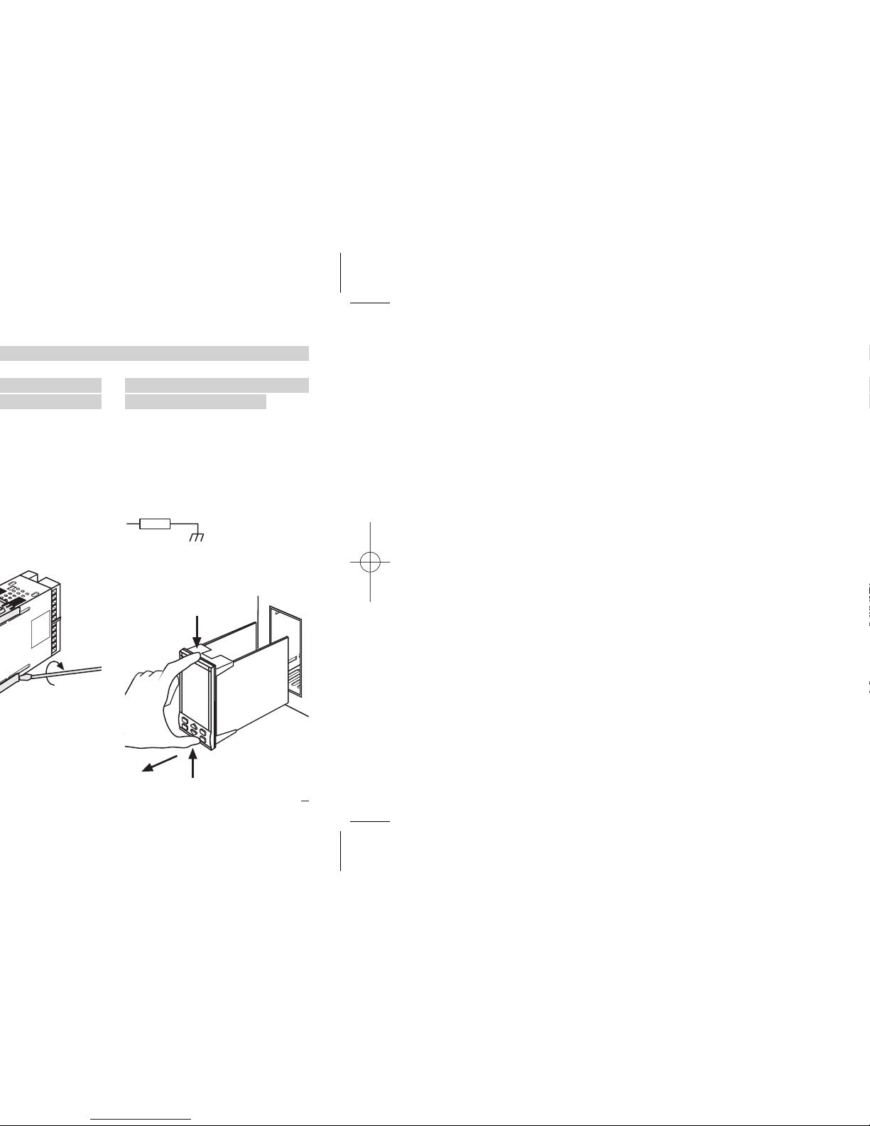
2.3.4 INSTRUMENT
REMOVAL
B
1 Push and
2 Pull to remove the instrument.
Electrostatic discharges can
damage the instrument.
Before removing the instrument
the operator must discharge
himself to ground.
1MΩ
2
1
1
Page 10
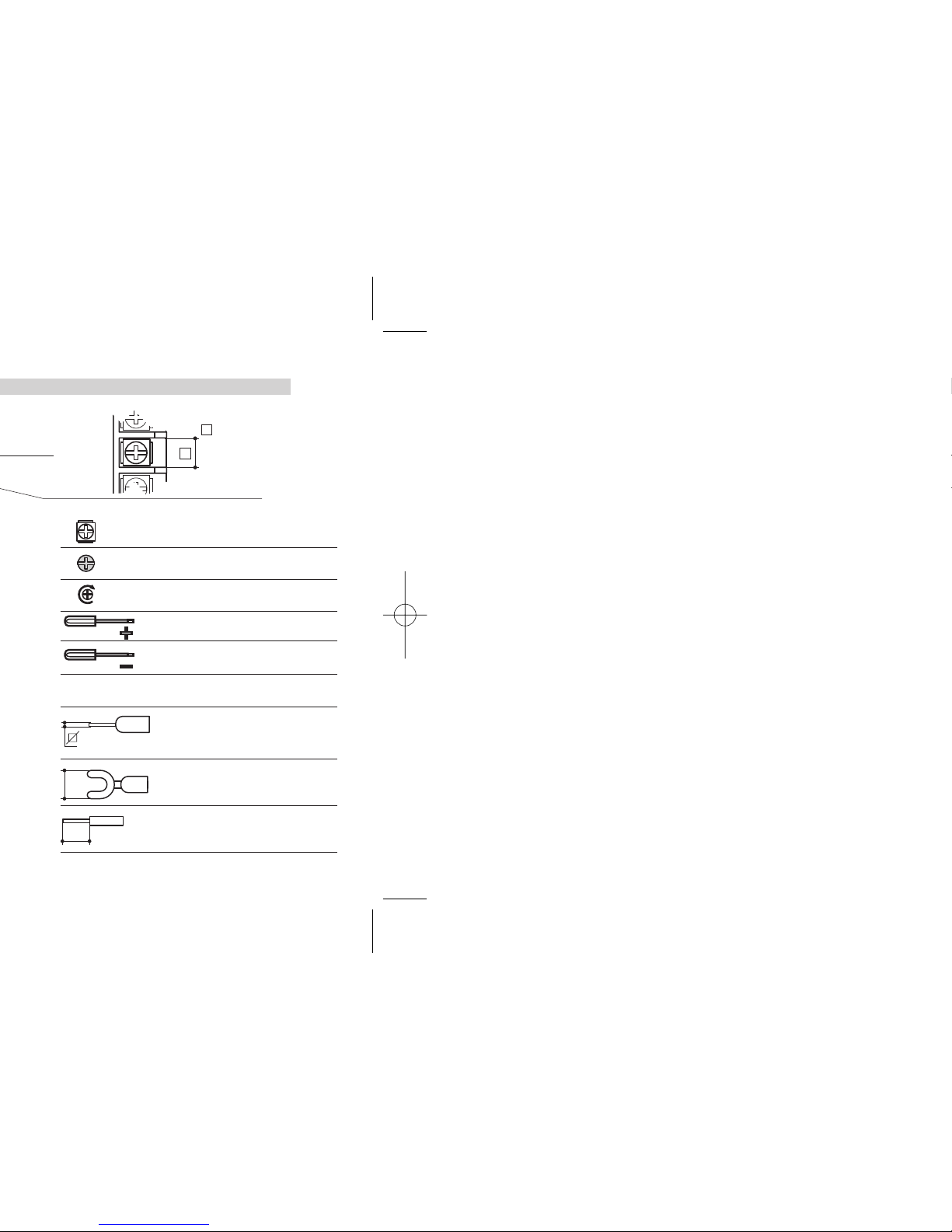
Terminals
Rear
terminal
cover
Cable size
1 mm
2
[2]
5.7 mm
0.22 in
B
35 screw terminals M3
Option terminals
Holding screw 0.5 Nm
Phillips screwdriver PH1
Flat blade screwdriver
0.8 x 4 mm
Pin connector
q 1.4 mm - 0.055 in max.
Ø
Fork-shape AMP 165004
Ø 5.5 mm - 0.21 in
L
Stripped wire
L 5.5 mm - 0.21 in
Page 11
28
27
30
29
26
25
19
31
20
32
33
34
23
35
24
36
16
15
18
17
14
13
21
A B
11
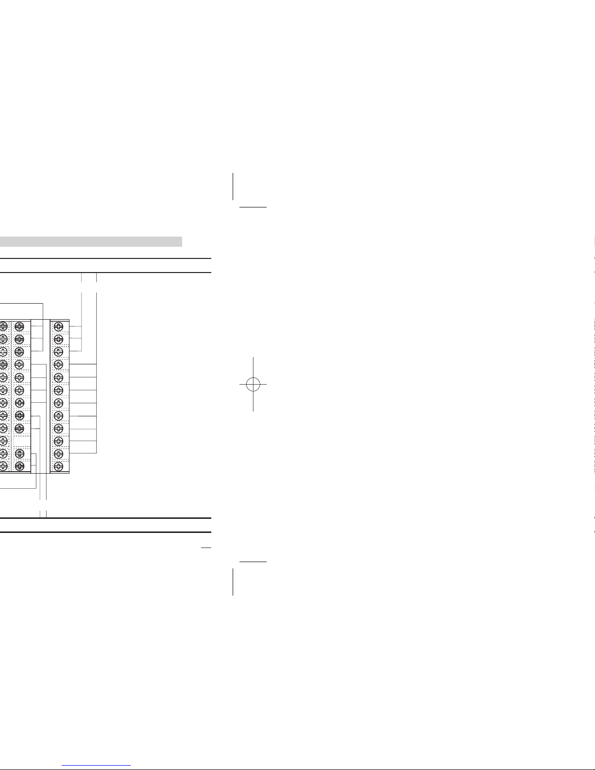
3 - Electrical Connections
B
A = Supply
B = Outputs
C = Analog inputs
D = Analog output
E = Digital input
Serial Comm.s
Page 12

B
Notes:
1] Ensure that the power supply voltage is
the same as that on the instrument label.
2] Switch ON the power supply only after
all electrical connections have been
completed.
3] In accordance with electrical safety reg-
ulations, there must be an easly identifiable and accessable power disconnect.
4] The instrument is PTC protected.
In case of failure, return the instrument to
the manufacturer for repair.
5] To protect internal circuits use:
- 2 A
~ T fuse for Relay outputs (220 Vac)
- 4 A~ T fuse for Relay outputs (110 Vac)
- 1 A~ T fuse for Triac outputs
6] Relay contacts are protected with varis-
tors.
In case of 24 Vac inductive loads, use
model A51-065-30D7 varistors (on
request).
Page 13
13
3 - Electrical Connections
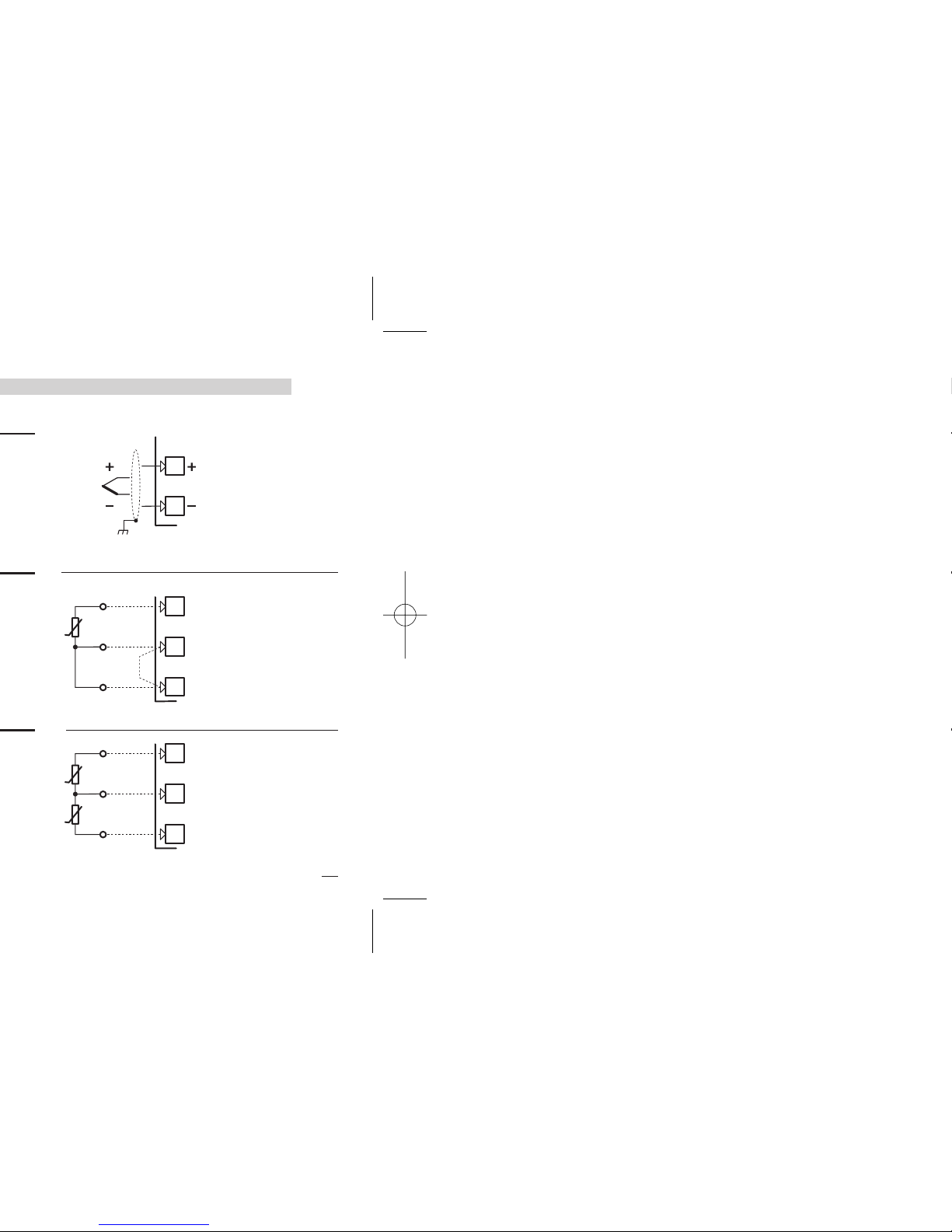
B
Wire resistance
150Ω max.
Only for two wires
system, put a
jumper between terminals 11 and 12.
Use wires of the
same length and 1.5
mm
2
size.
Maximum line resistance 20 Ω/line.
10
11
12
A
B
A
R2
R1
10
11
12
A
b
B
11
12
Page 14

Page 15

15
3 - Electrical Connections
B
3
7
6
TTL
o.c.
Isolated
contact
Com.
IL 3
IL 2
C2
C3
5
NPN
o.c.
IL 1
C1
Page 16
B
OP6
OP6
OP6
OP6
OP6
OP6
Page 17

17
3 - Electrical Connections
B
B
B
Fuse
Coil of the cool
load contactor
32
33
OP2
[1]
Cool
load
Static
Relay
8
9
OP5
8
9
OP5
Cool
load
mA mV,V
Page 18

Notes for pages 17 - 18 - 19
OP1 - OP2 Relay output
• SPST Relay N.O., 2A/250 Vac
(4A/120Vac)
for resistive load,
• Fuse 2A ac T at 250V, 4A ac T at 110V.
OP1 - OP2 Triac output
• N.O. contact for resistive load of up to
1A/250 Vac max.
• Fuse 1A ac T
Isolated digital outputs OP5-OP6
• 0…24Vdc, ±20%, 30 mA max.
Isolated analog outputs OP5-OP6
• 0/4…20mA, 750Ω / 15V max.
0/1…5V, 0…10V, 500Ω / 20mA max.
[1] Varistor for inductive load 24Vac only
Page 19

19
3 - Electrical Connections
3.3.6-G MOTOR POSITIONER OUTPUT
RELAY (TRIAC) / RELAY (TRIAC)
Valve drive PID without potentiometer 3 pole
output with N.O. contacts (raise, lower, stop)
OP1
33
32
31
OP2
V~
Lower
Raise
M
~
Page 20
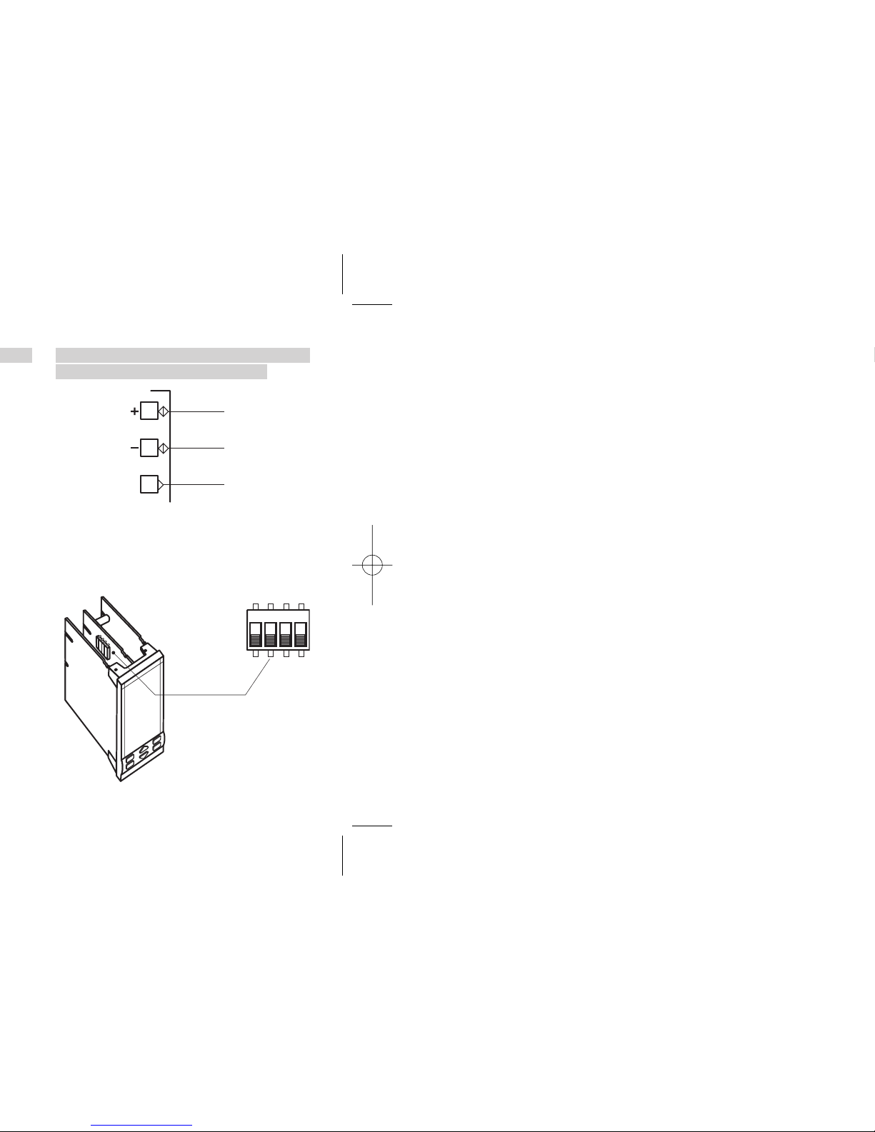
3.3.9 SERIAL COMMUNICATIONS
(OPTION) [2]
B
• Galvanic isolation 500Vac/1 min;
Compliance to the EIA RS485 standard
for Modbus/Jbus;
• Termination setting dip switches.
C
SLAVE
13
14
15
1234
SLAVE
Page 21
B
21
3 - Electrical Connections
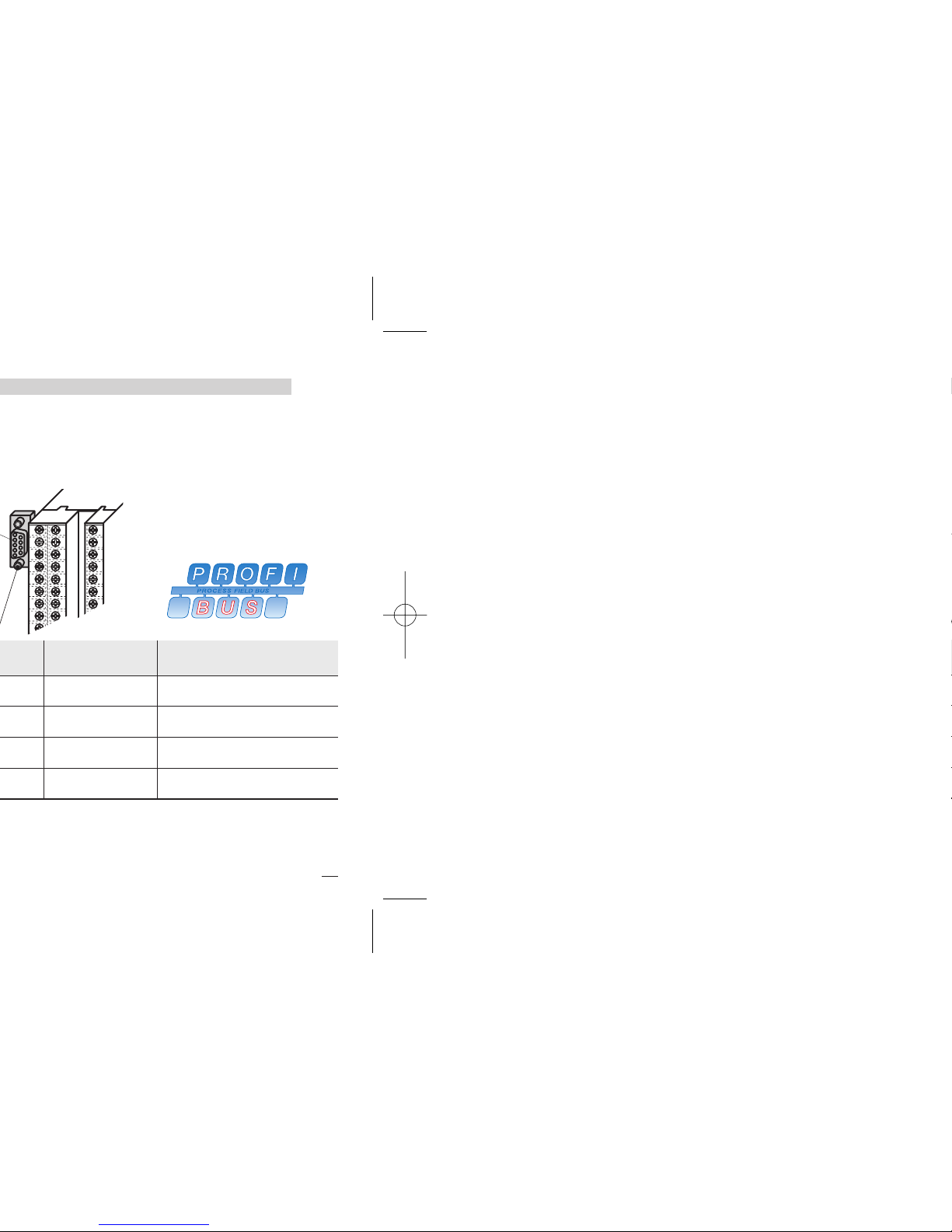
33
Description according to
PROFIBUS specifications
Receive data/transmission
data plus
Receive data/transmission
data negative
VP (VP)
Data transmission potential
(ground to 5V)
Supply voltage of the terminating resistance-P, (P5V)
Page 22

SP operating Setpoint
(Local/Remote or Stored)
% Control output
or Program status (see page 64)
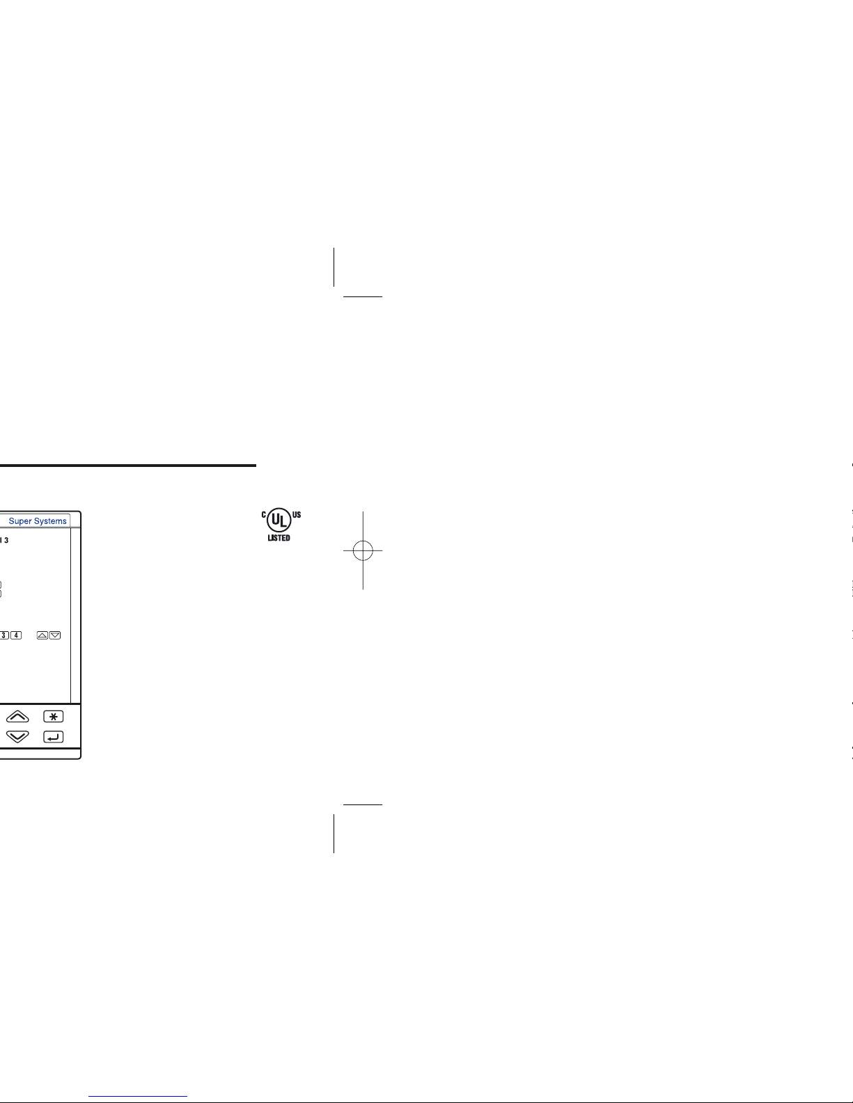
Control output LEDs (red)
å OP1/OP4 ON - ç OP2/OP4 OFF
Run/stop Timer or a program
Entry key for selection and value setting confirmation
Setpoint setting
Menu access
8888____ 8888----
PV control input in engineering units
Over range Under range
Page 23

23
4 - Operation
Parameter value
Value modification
Page 24

Unit
°f
Unit
none
Unit
ph
Engineering
Units
Celsius
Degree
Fahrenheit
Degree
Celsius
Degree
Fahrenheit
no units
defined
Ph
Page 25

25
4 - Operation
33
OK
EHit
Conf
ConfConf
tiMe
Conf
(see page 30... 33)
(see page 34)
NOYES
Back to the operator mode
Enter the configuration
password
Must be equal to the
value
of the parameter
C.Pas (see page.50)
from -999...9999
(33 default from factory)
Alarms
Timer
configuration
Exit the
Configuration
Page 26

Hertz
ph
Hz
PInp.
32…1112°F
Engineering
units
-58.0…122.0°F
-99.9…572.0°F
-328…1112°F
-328…752°F
32…2912°F
32…2912°F
32…2192°F
32…1112°F
Value Description
éUnit
Tab. 2 Engineering units
none
None
rh
°C
Degree centigrade
°f
Degree Fahrenheit
Rh
MA
mA
MU
mV
U
Volt
Ph
bar
bar
psI
PSI
Frequency
(option)
32…3272°F
32…2192°F
32…1112°F
32…3632°F
32…3632°F
éInP.
32…2012°F
Notes:
[1]
NiChroSil-NiSil thermocouple.
[2] Ni-Mo thermocouple.
[3] Factory default for the
custom range is: type K
(32... 2448°F).
Page 27

27
4 - Operation
Tab. 4 Rem. Setpoint
Value Description
0=5
0…5 Volt
1=5
1…5 Volt
0=20
0…20 mA
Tab. 3
4=20
4…20 mA
Setpoint type
0=10
reM.t
Remote - trim
0…10 Volt
érs.In
loc.t
Local - trim
l=r
Local/remote only
reM
Remote only
loc
Local only
Value Description
éS.P.ty
Page 28

rt. 2
énone
O.rt.2
é4=20
rt.L2
é 0
rt.H2
é9999
WITH OPTIONAL OP6 ANALOG
OUTPUT NOT USED AS COOL CON-
TROL OUTPUT
1
st
retransmitted
output selection
none/ P.U./S.P.
1stretransmission
output
see table 8
1
st
retransmission
low range
whole range
1
st
retransmission
high range
whole range
2
nd
retransmitted
output selection
none/P.U/S.P./M.U.
2ndretransmission
output
see table 8
2
nd
retransmission
low range
whole range
2
nd
retransmission
high range
whole range
Page 29

29
4 - Operation
Retransmitted
signal
none/P.U./S.P
/M.U.
Output
range
0=5 /1=5 /0=10
0=20 / 4=20
Retransmission
low
range
Retransmission
high
range
Example:
• T/C S: range 0…1600°C;
• Output range, 4…20 mA;
• Retransmitted signal PV on
800…1200°C range.
#rt.H1
#rt.H2
20
4
800 1200 1600
#retr = 4=20
#rt.H = P.U.
#rt.L1 = 800
#rt.H1 =1200
mA
°C
With rt.lI greater than
rt.H1 it is possible to obtain
a reverse scale.
Page 30

bloc
éno
Ltch
éno
A1.Ou
éOP1
AL. 1
éOFF
donb
éno
AL1 alarm type
see table 11
AL1 addressing
OP1 / OP2 [1]
OP3 / OP4
AL1 latching
no / yeS
AL1 start-up
disabling
no / yeS
Disables AL1 if a sensor break occurs
no / yeS
NOT AVAILABLE
OF
AL. 1 = OFF
Page 31

31
4 - Operation
AL4 alarm type
see table 11
AL4 addressing
OP1 / OP2 [1]
OP3 / OP4
AL4 latching
no / yeS
AL4 start-up
disabling
no / yeS
Disables AL4 if a sensor break occurs
no / yeS
Band
éAl 4
Description
Tab. 11 Alarm type
éAl 1
Value
Off
Not used or used by the
program (AL3/AL4)
fs.H
Active High
Absolute
fs.l
Active Low
deU.H
Active High
Deviation
deU.l
Active Low
bno
Active Out
bni
Active In
lba
Loop break alarm
(AL1 only)
éAl 3
éAl 2
tiMe
Alarm 3 active when
Timer ON
Page 32

Active high
é-fsH
On
Off
High rangeLow range
Active high
On
Off
+ range- range
é-deH
On
Off
SP
Alarm threshold
full scale
hyd hyu
∆SP ∆SP
[B] ALARM ACKNOWLEDGE
FUNCTION
The alarm, once occurred, is
presented on the display until
acknowledged. The acknowledge
operation consists in pressing any
key.
After this operation, the alarm
leaves the alarm state only when
the alarm condition is no longer
present.
Ltch
Yes
Page 33

mA
°C
OP1
275.0
A / M
1 2 3
Ilba
4
33
4 - Operation
LOOP BREAK ALARM (LBA)
When the controller connection to
the sensor is discontinued or
other faults are detected in the
control loop, AL1 alarm becomes
active after a predefined time of
1... 9999 s from the detection of
the failure (see page 37).
When a sensor failure occours,
the LBA interventrion is immediate. The alarm state ceases when
the fault condition is no longer
present.
eIn case of ON-OFF control, the
LBA alarm is not active.
#donb = no
#donb = yes
Page 34

Menu
AL
Menu
time
(see pages 37)
Operator
mode
(see page 41)
Alarm
menu
Time
menu
A
The parameter setting procedure
has a timeout. If no keys are
pressed for, at least, 30 seconds,
the controller switches back, automatically, to the operator mode.
Page 35

35
4 - Operation
Menu
Conf
Menu
AccS
(see page 54)
Access
menu
(see page 25)
Configuration
menu
menu
Page 36

SL. u
SL. d
éOFF
éOFF
S.P. H
éH.réange
S.P. L
éL.réange
Ratio Setpoint
-9.99…99.99
Remote
Setpoint bias
full scale
Setpoint
low limit
full scale
Setpoint
high limit
full scale
Slope up
0ff/1…9999 digit/
[1]
Slop down
0ff/1…9999
digit/..
0ff/1…9999
digit/ [1]
Page 37

37
4 - Operation
Timer
Action
Timer OP
function
std/eHpd
standard/extended
Standard: tdop = 0
OP3 is set to 1 at timer lauch
and reset 0 on time elapsing.
Extended: tdop = 1
OP3 is set to 1 at time
elapsing and set to 0 by reset
command.
P.I.D enable
yes/no
Yes:
PID is enabled when time
function is enabled.
Extended:
PID is disabled and output is
maintained at zero.
#Pid
#tdop
[1] OP3
status
Value
On
4
Off
5
On
6
Off
7
Page 38

C - Counting start time = timer launch
time, end in control mode.
The time counting starts when the timer is
launched. The control action is not affected
by the Timer function.
tdop = 1
tdop = 0
#tiMe
Timer
launch
SP
Process
variable PV
Output OP [2]
#t.Mod = 4
OP3
Reset
OP3
OP = 0
Page 39

39
4 - Operation
F - Control action with stand-by Setpoint
during the counting time.
The time counting starts when the timer is
launched and the control action use the
Stand-by Setpoint. At the end, the control
action use the working Setpoint.
tdop = 1
tdop = 0
#tiMe
Timer launch
#s.p. 2
#t.Mod =7
SP
Process
variable PV
Output OP [2]
OP3
Reset
OP3
OP = 0
Page 40

Page 41

41
4 - Operation
Alarm 3 hysteresis
asymmetric upper
0…5% Span
in engineering units
Alarm 3 hysteresis
asymmetric lower
0…5% Span
in engineering units
Alarm 3 delay
OFF/1...9999
Alarm 4 hysteresis
asymmetric upper
0…5% Span
in engineering units
Alarm 4 hysteresis
asymmetric lower
0…5% Span
in engineering units
Alarm 4 delay
OFF/1...9999
Type and value Mode
No. and
Param.
Absolute
full scale
Active high
-fs.H
Active low
-fs.l
Deviation
full scale
Active high
-de.H
Active low
-de.l
Band
full scale
L.B.A.
1…9999 s
Active high
-lba
Timer
ON on timer
signal
Alarm 3
active on
timer signal
-ton
[1] A code, specifying the No. and the
alarm type that has been configured (see page 31), is displayed. At
this point, the user must enter the
threshold value, according to the
following table.
Active out
-bno
Active in
-bni
Page 42

OK
t.d. C
é 12:0
t.i. C
é 60
P.b. C
é 5:0
Proportional band
Cool channel
0.5…999.9%c.s.
Cool
Integral time
0ff/1
…
9999 s
Cool
Derivative time
0ff/0.1
…
999.9 s
NO
YES
Page 43

43
4 - Operation
Menu
InP
T.SaM
é 0:11
In.Sh
é 0
t.FiL
éOFF
Filter time constant
(user enabled/disabled)
Off/0.2…99.9 seconds
Measure bias
-60…60 digit
Sampling time
0.1…10.0 seconds
Input
menu
Page 44

Op.rC
é Off
OP.C.H
t.c. C
é 10:0
é100:0
d.bnd
é 0:5
Motor travel time
15…600 seconds
Minimum
output step
0.1…5.0%
Dead band
0.0…5.0%
Cool cycle time
(time proportional only)
0.2…100.0 s
Cool control output
high limit
(PID only)
0.0…100.0%
Cool output rate limit
(user enabled/disabled)
0ff/0.01…99.99%s
Heat / Cool
Algorithm
Page 45

45
4 - Operation
Page 46

Target Setpoint
= 350°C
t = 10
#
sL. u = 10
digit/minute
1st stored
Setpoint
2nd stored
Setpoint
3th stored
Setpoint
Values of the three Setpoints,
that are activated by mean of
logic inputs, communication
parameters, and keyboard. The
Setpoint active is indicated by
the ú, ù or û green LED.
See page 56 for further explanation.
Remote Setpoint
Slope enable
To enable or disable slopes when
the remote Setpoint is active.
#rs.sl
#S.P. 3
#S.P. 2
#S.P. 1
Page 47

47
4 - Operation
bias = 20
ratio = 0.1
ratio = –0.1
Range
600
100
20
Remote
Setpoint span
bias = 100
a b
a´ b´
HR
´ ) b (a´ )
PV = Process Variable
LR = PV low limit
HR = PV high limit
SR = Remote Setpoint
a (a´) = SR starting point
b (b´) = SR ending point
Page 48

Asymmetric
upper alarm
hysteresis
Asymmetric
lower alarm
hysteresis
Alarm
delay
Delay time for alarm activation.
OFF: alarm activated immediately
1...9999 seconds: alarm activated only if the condition persists for the set time
#tF1
=
#hy-u
Page 49

49
4 - Operation
Manual
reset
Error
Dead Band
4.5.4 TUNING MENU
(not shown for ON-OFF
main control output)
See page also 57
Two tuning method are provided:
• Initial one shoot Fuzzy-Tuning
• Continuous, self learning
Adaptive Tuning
The Fuzzy-Tuning automatically
determines the best PID term with
behaviour respect to the process.
The controller provides 2 types
of “one shot” tuning algorithms,
that automatically are selected
according to the process conditions when the tune operation
is started.
STEP response
SP
End of the tuning
operating and
setting of the new
calculated terms
Start of autotune
operation
Setpoint change
PV variable
Control output
Page 50

4.5.5 INPUT MENU
Input
filter
Time constant, in seconds, of
the RC input filter on the PV
input. When this parameter is
Off the filter is bypassed.
Measure
Bias
This value is added to the measured PV input value. Its effect
is to shift the whole PV scale of
its value (±60 digits).
Sampling
Time
Sampling time, in seconds, of
the instrument. This parameter
is normally used when controlling slow process, increasing the
sampling time from 0.1... 10 s.
#t.SaM
#In.sh
0
PV
63.2%
Filter time
Time
#t.fil
Page 51

51
4 - Operation
Soft start
time
Travel
time
Minimum
step
#Op.r
Time
Speed in %/s
Heat/Cool
deadband
This parameter specifies the
width of the deadband between
the Cool and the Heat outputs.
#d.bnd
#OpC.H
#
Op.H.
0
100%
100%
0
SP
d.bnd
P.b. / CP.b.
eat / Cool Algorithm
Heat Cool
100%
Cool output
Heat output
Heat
Page 52

Page 53

53
4 - Operation
Page 54

Ac.le
C.pas
Oper
EHec
C.pas
33
Access
to all the levels
[1]
Execute
the following
operations
A/M enable
yes/nO
Operator
level Access
Change the
Configuration
password
Enter
the Configuration
password
Page 55

pot.H
EHec
C.pot
pot.l
O
255
55
4 - Operation
Calibrate
the potentiometer
(if present)
The valve
goes to low scale
The valve
goes to full scale
Download the data
to Memory chip
When the indication
(the valve) is stopped,
confirm the calibra-
tion value using
$ or %
Page 56

The parameters in the access
level
fast are recalled on the
front panel through the procedure of fast parameter
access illustrated in par. 5.2
page 57. The maximum number of fast parameters is 10.
At the end of the parameter list of
the selected group, the controller
exits from the Edit access level.
Therefore, the Edit level must
be selected for each group of
parameters
The access level of groups and
parameters is activated through:
Ac.le
Oper
Access
level operator
Confirm
Page 57

57
5 - Displays
Operator mode
Automatic mode
One shot
tune start
no/yes
Alarm 3 threshold
(high absolute
alarm)
full scale
Stored Setpoint
selection
none/s.LOC/
s.s.p.I/s.s.p.2/
s.s.p.3
5.2 FAST VIEW
(fast access to the parameters)
With this procedure, up to 10
parameters, selected through
the fast view (see par 4.6 page
56) are displayed and can be
modified by the operator
without requiring the standard
parameter setting procedure.
Press
$% in order to
modify the parameters.
The value is entered by
pressing è key.
On left side, please find a
sample list of parameters on
Fast view menu.
Page 58

6.3 SERIAL
COMMUNICATIONS
see the manual on this topic
Page 59

59
6 - Commands
275.0
274.8
63
275.0
274.8
35
275.0
274.8
63
A
Operator
mode
(automatic)
The bumpless action is present
switching between AUTO, MAN
and vice versa.
AUTO AUTO
SP = PV
OPMAN=OPAUTO
SP (PV)
O
Y
0
0
MAN
Op.r
SP
change OP
100%
Setpoint SP
with
100% output OP
OPAUTO=OPMAN
PV
OP
AIn case of power failure, the
AUTO/MAN status and the
output value remain stored in
the controller memory.
Page 60

s.sel
s.sel
S.LOC
s.sel
s.s.p.1
s.s.p.3
The selected Setpoint
becomes operating
pressing the
è key.
The three
ú ù û
leds flag the Setpoint
operating.
Page 61

tune
tune
no
tune
yes
no
61
6 - Commands
Confirm
yes
to start
Confirm
no
to stop
The command start/stop
is executed pressing the
è key.
When the controller is
calculating the PID
parameters, the green
Ä led is ON.
Fuzzy Tune
start-up
After the execution of the tuning, the
calculated values are automatically
presented in the PID menu.
Page 62

Notes
With the keypad locked the commands from digital
inputs and serial communications are still operating
The value of PV is “frozen” at the time the digital input
goes to the close state
The permanent closure forces the chosen stored value.
Setpoint modification is not possible.
The impulsive closure, selects the stored value. Setpoint
modification is allowed. If more than one digital input
is selecting a Setpoint, the last to be activated is the
operating one (see page 43)
When the input is in the on state, the Setpoint is changed
in steps
With ON command the output is equal to the forced
value (see page 28)
The blocking function is activated on closing the command from digital inputs
Page 63

63
8 - Technical Specifications
- the type and functionality of the alarms
- control parameter values
- access levels
Between 100…240Vac
the error is minimal
Max. wire Res: 20Ω max. (3 wires)
Input drift: 0.1°C/10° T
env
<0.1°C/10Ω Wire Res.
Line: 150Ω max.
Input drift: <2µV/°C. T
env.
<5µV/10Ω Wire Res.
—
Input drift: <0.1%/20°C T
env.
<5µV/10Ω Wire Res.
Page 64

Bias in engineering units and ± range
Ratio: -9.99… +99.99
Local + Remote Setpoint
OP2
OP3
Relay
OP4
Relay
OP5
Analog/Digital
OP6
Analog/Digital
OP2
OP3
Relay
OP4
Relay
OP6
Analog/Digital
OP3
Relay
OP4
Relay
OP5
Analog/Digital
OP6
Analog/Digital
OP2
OP3
Relay
OP4
Relay
OP6
Analog/Digital
OP3
Relay
OP4
Relay
OP6
Analog/Digital
OP2
OP3
Relay
OP4
Relay
OP3
Relay
OP4
Relay
OP5
Analog/Digital
OP6
Analog/Digital
Feedback valve position
Page 65

65
8 - Technical Specifications
Single action
PID algorithm
OFF = O
Double action
PID algorithm
(Heat / Cool)
OFF = O
Valve drive PID algorithm
Raise/Stop/Lower
OFF = O
OFF = O
Page 66

0/4... 20mA, 750Ω/15V max.
Page 67

67
8 - Technical Specifications
Power consumption 5W max.
Page 68

Factory default parameters
FACTORY DEFAULT PARAMETERS
Parameter Parameter Name Default value User settings Notes
S.SEL
Setpoint selection NONE
SP.1
1st stored Setpoint 0
SP.2
2nd stored Setpoint 0
S.P.L
Setpoint low limit PV.LO
S.P.H
Setpoint high limit PV.HI
Sl.u
Setpoint ramp up OFF
Sl.d
Setpoint ramp down OFF
rtio
Ratio remote Setpoint 1.00
biaS
Remote Setpoint Bias 0
1
AL1 alarm threshold 0
SSI.fm Page 68 Friday, December 12, 2008 5:04 PM
Page 69

Factory default parameters
tFl1
AL1 delay 1
Hy.2u
AL2 alarm hysteresis Up 1
Hy.2d
AL2 alarm hysteresis Down 1
tFl2
AL2 delay 1
Hy.3u
AL3 alarm hysteresis Up 1
Hy.3d
AL3 alarm hysteresis Down 1
tFl3
AL3 delay 1
Hy.4u
AL4 alarm hysteresis Up 1
Hy.4d
AL4 alarm hysteresis Down 1
tFl4
AL4 delay 1
t.Mod
Timer Operating Mode 0
t.act
Timer Action 4
t.dOP
Timer OP Function 1
Parameter Parameter Name Default value User settings Notes
SSI.fm Page 69 Friday, December 12, 2008 5:04 PM
Page 70

Factory default parameters
t.i.
Integral time 60
t.d.
Derivative time 12.0
d.Err
Error Dead Band OFF
O.C.
Overshoot Control 0.8
O.C.r.b.
Overshoot Control relative band 1.0
MreS
Manual Reset 50
P.b. C
Cool proportional band 3.0
t.i. C
Cool integral time 60
t.d. C
Cool derivative time 12.0
tune
Start/Stop One shot tuning (0=Stop 1=Run) NO
AdPt
Start/Stop Adaptive tuning (0=Stop 1=Run) NO
t.Fil
Input filter 2.0
In.Sh
Input shift OFF
Parameter Parameter Name Default value User settings Notes
SSI.fm Page 70 Friday, December 12, 2008 5:04 PM
Page 71

Factory default parameters
OP.r
Control output maximum speed OFF
St.OP
Soft start output high value OFF
St.tM
Soft start time 10
M.t
Output minimum step Servomotor 60
M.hy
Output minimum step Servomotor 0.5
d.bnd
Heat/Cool Dead band 0.5
tc.C
Cool cycle time 5.0
OP.C.H
Cool output maximum value 100.0
OP.rC
Cool output maximum speed OFF
Add.S
Communication SLAVE address 247
dr.S
SLAVE Baud rate 9600
Pro.S
SLAVE Communication protocol MBUS
Par.y
Parity NONE
Parameter Parameter Name Default value User settings Notes
SSI.fm Page 71 Friday, December 12, 2008 5:04 PM
Page 72

Factory default parameters
A.PAS
Access password 11
In
Input type selection 0 - 10
Unit
Engineering units NONE
SC.dd
Number of decimals (0... 3) 0
SC.lo
Low range 0
SC.Hi
High range 9999
Sqr
Square root (0 = OFF, 1 = ON) NO
Char
Linear input characterization NO
S.P.ty
Setpoint type LOC
S.P.tr
Stored Setpoint tracking NO
S.P.T
Time units and Setpoint slope P.SEC
.In
Remote Setpoint input 4 - 20
Parameter Parameter Name Default value User settings Notes
SSI.fm Page 72 Friday, December 12, 2008 5:04 PM
Page 73

73
Warranty
Page 74

Logic
mA mV
mA
SPDT Relay
Triac
SPST Relay
Output
Setpoint slopes
inhibition
PV hold
Run, Hold, Reset and
program selection
Auto/Manual
Digital input
connected functions
 Loading...