

Page 1

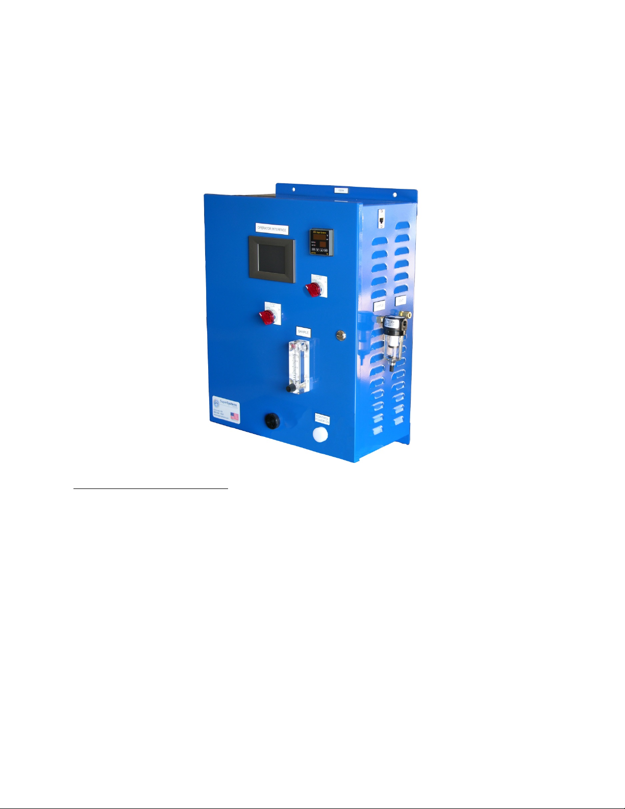
Model 1500 VRSD
Dew Point Analyzer,
9125 Temperature Control System,
and Video Recorder with
Dew Point Sensor
OPERATIONS MANUAL
Super Systems Inc.
7205 Edington Drive
Cincinnati, OH 45249
513-772-0060
Fax: 513-772-9466
www.supersystems.com
Page 2

Model 1500 VRSD Operations Manual
Contents
Introduction ........................................................................................................................................ 4
More About Dew Point Analysis ..................................................................................................... 4
Warnings ......................................................................................................................................... 5
Specifications ..................................................................................................................................... 5
Dew Point Sensor ............................................................................................................................... 6
Factory Calibration ......................................................................................................................... 6
Field Calibration ............................................................................................................................. 6
Controller and Touch Screen .......................................................................................................... 11
Startup .............................................................................................................................................. 11
Operation .......................................................................................................................................... 12
Returning the Unit to SSi ................................................................................................................. 12
Equipment Drawings – Part Number 13599 (Model 1500 VRSD for single-tube generator) ........ 14
Equipment Drawings – Part Number 13671 (Model 1500 VRSD for two-tube generator) ............ 18
Replacement Parts List ................................................................................................................... 22
Warranty ........................................................................................................................................... 23
Revision History ............................................................................................................................... 24
APPENDIX “A” – Determining the Dew Point in °F ......................................................................... 25
APPENDIX “B” – Determining the Dew Point in °C ........................................................................ 26
APPENDIX “C” – Determining the sensor temperature in °F ........................................................ 27
APPENDIX “D” – Determining the sensor temperature in °C ........................................................ 28
Super Systems Inc. Page 2 of 28
Page 3

Model 1500 VRSD Operations Manual
Super Systems Inc.
Super Systems Europe
Super Systems México
Super Systems China
USA Office
Corporate Headquarters
7205 Edington Drive
Cincinnati, OH 45249
Phone: (513) 772-0060
http://www.supersystems.com
Sistemas Superiores Integrales S de RL de CV
Calle 3 Int.: 11.
Zona Ind. Benito Juarez
Querétaro, Qro. Méx.
C.P.: 76120
Phone: +52 (442) 210 2459
http://www.supersystems.com.mx
Units 3 & 4, 17 Reddicap Trading Estate,
Sutton Coldfield, West Midlands
B75 7BU
UNITED KINGDOM
Phone: +44 (0) 121 329 2627
http://www.supersystemseurope.com
No. 335 XianXia Road
Room 308
Shanghai, CHINA
200336
Phone: +86 21 5206 5701/2
http://www.supersystems.com
Super Systems Inc. Page 3 of 28
Page 4
Model 1500 VRSD Operations Manual
Introduction
The 1500 VRSD (Part Number 13599 and 13671) is an SSi Standard System designed to maintain
a consistent atmospheric dew point by monitoring dew point measured by a dew point sensor
and using an SSi 9125 Controller to control the process. A 3.5” color touch screen provides a
control interface and data logging.
More About Dew Point Analysis
A dew point analyzer measures the amount of moisture present in a gas to determine the
theoretical temperature at which the moisture in the gas will condense (the saturation point).
Although dew point is related to the temperature and the pressure of the gas, the dew point of a
gas remains the same regardless of the actual temperature of the gas. Knowing the dew point
of a gas in a heat treating environment can be beneficial in either determining the carbon
potential of the gas, or determining the purity level of the incoming process gases.
The SSi dew point sensor in the 1500 VRSD is considered a high range (“standard”) sensor; it is
designed for gases with temperatures above 0°F (-17.8°C). The sensor uses the relative
humidity (%RH) and the gas temperature to perform a calculation to determine dew point.
On a more technical level, the dew point sensor is a “dielectric ceramic” that varies its electrical
capacitance with changes in relative humidity. The sensor is mounted in a short probe, which is
installed in a T-fitting that allows the sample gas to flow past the sensor. The tip of this probe
contains the dielectric ceramic relative humidity (RH) sensor, as well as a built in temperature
sensor to determine its dry bulb temperature. Information from both of these sensors is used
to compute the resultant dew point.
Super Systems Inc. Page 4 of 28
Page 5

Model 1500 VRSD Operations Manual
IMPORTANT!
Warnings
Although it is intended for use in an industrial environment, this is a sensitive piece of
analysis equipment. Care should be taken not to operate it in a manner inconsistent
with its intended use.
• Moisture (water) cannot be allowed to enter the unit. If water is present in the
sample gas, use an in-line dryer for sample conditioning. In the event that the
sensor becomes wet, use an inert gas (Nitrogen or Argon) to dry the inside of the
instrument. Under no circumstances should Methane (Natural Gas) be used to dry
the unit.
• The analyzer must be stored at ambient temperature (65-80°F) for at least four
hours prior to operation.
• An in-line dryer for sample conditioning should be used for exothermic and
combustion applications.
• This unit is not designed to measure the dew points in corrosive gasses, such as
Ammonia, S0
, Chlorine, and HCL.
3
Failure to comply with these conditions may cause damage to the unit that will not be
covered under the warranty. Super Systems, Inc. is not responsible for damage to this
unit caused by disregard of these warnings, neglect, or misuse.
Specifications
Measurement Range: 0 to +80°F (-17.8 to +27°C)
Temperature Range: 0 to +120°F (-18 to +49°C)
Accuracy: +/- 1°F (+/- 0.5°C)
Zero and Span Drift: +/- 1°F (+/- 0.5°C)
Power Supply: 115 VAC 60Hz (Optional 220VDC)
Display Type: 3.5” Color Touch Screen
Display Resolution: +/- 1°F (+/- 0.1°C)
Digital Communications: (2) RS485, RS232, Ethernet
Control / Retransmission Output: 4 – 20 mA (2 Outputs)
Alarms: Up to 3 Alarm Relays
Dimensions: 20” x 16” x 10” (508mm x 406mm x 254mm)
Weight: 34.4 lbs. (15.6 kg)
Super Systems Inc. Page 5 of 28
Page 6

Model 1500 VRSD Operations Manual
Dew Point Sensor
Factory Calibration
Factory calibration is recommended every six months if the unit is used regularly. SSi’s
calibration is NIST traceable and includes a numbered “Certificate of Calibration”. This
certificate also indicates the accuracy of the analyzer before and after calibration.
Please contact Super Systems at (513) 772-0060 for more information regarding this
service.
Field Calibration
It is also possible to calibrate the VRSD in the field, which will require the optional
calibration kit (Part Number 31030) and a voltmeter that will allow you to measure
between 0 and 1 volt DC. Since there is no temperature display on the instrument itself,
the voltage from the sensor circuit board will have to be translated into a temperature
measurement for the purpose of verifying the calibration. The instructions for doing
this are contained in this document along with reference charts to aid in the
interpretation of the voltages.
The calibration kit consists of two bottles of saturated salt solution in which each bottle
generates a precise relative humidity percentage (R.H.%) value. One bottle is 11.3%
R.H., and the other is 75.3% R.H. These two specific calibration points are already preprogrammed into the microprocessor board.
1.0 Open the unit.
1.1 Undo the latches on the side of the enclosure.
2.0 Locate the key components within the unit.
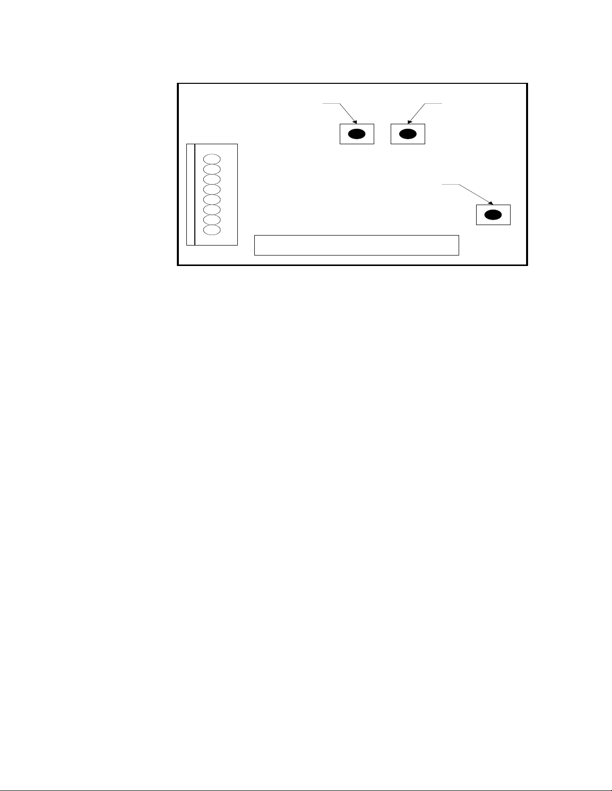
2.1 The microprocessor board is located in the front right side of the unit. This
board contains three very small buttons that are used for calibration. Two
are next to one another, and they are marked “75.3%” and “11.3%”, while the
other has no label. The unmarked button is the “Calibrate” button. The
approximate locations of each button are shown on this diagram:
Super Systems Inc. Page 6 of 28
Page 7
Model 1500 VRSD Operations Manual
SPAN
BUTTON
(75.3)
ZERO
BUTTON
(11.3)
CAL
BUTTON
Dew Point Microprocessor Board
2.2 The sensor-sampling chamber is located in the bottom left of the unit. It is
the gray rectangular box with brass barb fittings on either side and a black
plastic gland protruding from the center.
2.3 The sensor probe is positioned in the sensor sampling chamber. It is held
in place by the nut on the black plastic gland.
3.0 Remove the sensor probe from the sensor-sampling chamber.
3.1 Loosen the black plastic gland nut and slowly slide the sensor probe out
through the airtight seal. Care must be taken when removing this sensor
probe, since the tip is very delicate and can be easily damaged if it is
mishandled. Note that the probe has white mark at the wire entry point,
which must be aligned with corresponding white mark in plastic gland when it
is re-inserted in the sampling chamber.
4.0 Install the sensor probe into the 75.3% salt solution.
4.1 Slip the black sensor gland (supplied in the calibration kit) over the sensor
probe with the sensor tip protruding from the threaded end of the gland and
the sensor wires being flush with the top of the rubber o-ring in the gland.
Tighten the gland around the sensor. This does not need to be done with a
wrench or other tools, but it does need to be tight enough to prevent ambient
air from contaminating the humidity level of the sampling chamber.
4.2 Remove the cap of the 75.3% salt solution and install the sensor gland
(with the sensor) into the salt solution. To increase the life of the calibration
salts, an effort should be made to minimize the amount of time that the salt
solution is exposed to the ambient air.
Super Systems Inc. Page 7 of 28
Page 8

Model 1500 VRSD Operations Manual
5.0 Allow the sensor to reach equilibrium with the calibration salt.
5.1 With the power to the unit still turned off, leave the sensor in the
calibration salt for a minimum of eighteen (18) hours. It is acceptable to leave
the sensor in the salt solution for a longer period of time, even a few days, if
desired.
6.0 Begin the 75.3% (Span) calibration process.
6.1 After leaving the sensor in the salt for at least eighteen (18) hours, turn the
unit on. The reading on the display is not important at this point.
6.2 Simultaneously press the “75.3%” and “Calibration” buttons on the
microprocessor board.
7.0 Verify the 75.3% (Span) calibration.
7.1 Leave the sensor in the 75.3%RH calibration salt.
7.2 Record the temperature and the dew point of the sensor. Since there is no
display on the instrument, you will need to measure the voltage from the
microprocessor board and translate that into the appropriate measurement.
7.2.1 To determine the sensor temperature, measure the DC voltage
between pins 5(+) and 9(-) on the microprocessor board. The
voltage will be between 0 and 1VDC. Use the chart in Appendix C to
determine the temperature in °F, or use Appendix D to determine
the temperature in °C.
7.2.2 Temporarily record the sensor temperature.
7.3 Look up this temperature in Appendix “A” (Determining the Dew Point in
°F) or Appendix “B” (Determining the Dew Point in °C). Appendix A will show
the temperature values in Fahrenheit, and Appendix B will show the
temperature values in Celsius.
7.4 Next to the appropriate sensor temperature, note the number in the
corresponding column titled “75.3%”. This will match the measured dew
point, which can be verified wherever the dew point is displayed.
8.0 Determine the acceptability of the reading.
8.1 The value printed on the chart in Appendix A is a theoretical value, and
some variation can be expected. When a calibration is performed at SSi, we
certify (in writing) that the unit displays within +/- 1 degree of the theoretical
Super Systems Inc. Page 8 of 28
Page 9

Model 1500 VRSD Operations Manual
value after it has been calibrated. We would not consider a calibration to be
successful unless it is within +/- 1 degree; however, in the case of a field
calibration, this degree of accuracy may or may not be required. The degree
of accuracy that is acceptable is determined by the policy of the person
performing the calibration.
NOTE: Keep in mind that the VRSD only displays whole numbers, and not
tenths of a degree. Therefore, a reading of 65°F could be as low as 64.50 or
as high as 65.49.
9.0 Allow the sensor to achieve equilibrium at ambient atmosphere.
9.1 After the 75.3% (Span) calibration has been completed, remove the sensor
from the calibration salt and replace the cap on the salt.
9.2 Leave the sensor probe in the gland and while the unit is still on, allow it to
achieve equilibrium at the ambient atmosphere in the room. This is
accomplished by simply leaving the sensor exposed to ambient air for
between two and three minutes. You will know when this has been
accomplished when the numbers on the display begin to stabilize.
10.0 Install the sensor probe into the 11.3% salt solution.
10.1 Remove the cap of the 11.3% salt solution and install the sensor gland
(with the sensor) into the salt solution. To increase the life of the calibration
salts, an effort should be made to minimize the amount of time that the salt
solution is exposed to the ambient air.
10.2 Turn the unit off.
11.0 Allow the sensor to reach equilibrium with the calibration salt.
11.1 With the power to the unit still turned off, leave the sensor in the
calibration salt for a minimum of twenty-four (24) hours. It is acceptable to
leave the sensor in the salt solution for a longer period of time, even a few
days, if desired.
12.0 Begin the 11.3% (Zero) calibration process
12.1 After leaving the sensor in the salt for at least twenty-four (24) hours, turn
the unit on. The reading on the display is not important at this point.
12.2 Simultaneously press the “11.3%” and “Calibration” buttons on the
microprocessor board.
Super Systems Inc. Page 9 of 28
Page 10

Model 1500 VRSD Operations Manual
13.0 Verify the 11.3% (Zero) calibration
13.1 Leave the sensor in the 11.3%RH calibration salt.
13.2 Record the temperature and the dew point of the sensor. Since there is
no display on the instrument, you will need to measure the voltage from the
microprocessor board and translate that into the appropriate measurement.
13.2.1 To determine the sensor temperature, measure the DC voltage
between pins 5(+) and 9(-) on the microprocessor board. The
voltage will be between 0 and 1VDC. Use the chart in Appendix C to
determine the temperature in °F, or use Appendix D to determine
the temperature in °C.
13.2.2 Temporarily record the sensor temperature.
13.3 Look up this temperature in Appendix “A” (Determining the Dew Point
in °F) or Appendix “B” (Determining the Dew Point in °C). Appendix A will
show the temperature values in Fahrenheit, and Appendix B will show the
temperature values in Celsius.
13.4 Next to the appropriate sensor temperature, note the number in the
corresponding column titled “11.3%”. This will match the measured dew
point, which can be verified wherever the dew point is displayed.
14.0 Determine the acceptability of the reading.
14.1 The value printed on the chart in Appendix A is a theoretical value, and
some variation can be expected. When a calibration is performed at SSi, we
certify (in writing) that the unit displays within +/- 1 degree of the theoretical
value after it has been calibrated. We would not consider a calibration to be
successful unless it is within +/- 1 degree, however in the case of a field
calibration, this degree of accuracy may or may not be required. The degree
of accuracy that is acceptable is determined by the policy of the person
performing the calibration.
NOTE: Keep in mind that the VRSD only displays whole numbers, and not
tenths of a degree. Therefore, a reading of 18°F could be as low as 17.50 or
as high as 18.49.
15.0 Allow the sensor to achieve equilibrium at ambient atmosphere.
15.1 After the 11.3% (Zero) calibration has been completed, remove the sensor
from the calibration salt and replace the cap.
Super Systems Inc. Page 10 of 28
Page 11

Model 1500 VRSD Operations Manual
15.2 Leave the sensor probe in the gland and while the unit is still on, allow it
to achieve equilibrium at the ambient atmosphere in the room. This should
take between two and three minutes. You will know when this has been
accomplished when the numbers on the display begin to stabilize.
16.0 Re-assemble the unit.
16.1 After the calibration process has been completed, remove the sensor
probe from the gland and return it to the sensor-sampling chamber, taking
care to position it properly. The white mark on the sensor probe should face
towards the right of the sensor-sampling chamber (at 3:00 if it were the face
of a clock.). If the white mark is not visible, then it should be placed so the
sample flow directly strikes the face of the mirror on the sensor tip (the
sample flows from right-to-left). In other words, the mirror should face the
incoming gas stream.
16.2 Hand-tighten the black sensor gland to prevent air from leaking out of the
sampling chamber.
16.3 Verify that the system is leak proof by turning on the pump and placing a
finger over the sample inlet port. The flow meter will drop to zero if there are
no leaks. If a leak is detected, make sure that all tubing connections are
tight, especially the black sensor gland.
16.4 After the unit has passed the leak test, the enclosure door can be closed.
17.0 Make sure that all caps are replaced on the calibration salts, and return the
Model1500 VRSD to service.
Controller and Touch Screen
For information on the controller and touch screen operator interface, please reference
the 9125 controller operations manual.
Startup
The 1500 VRSD unit has been calibrated before shipment from Super Systems Inc. You
can begin typical operation as soon as the unit has been allowed to stabilize in a
temperature similar to the temperature in the heat treating department. This is
particularly important for units that may have been sitting overnight in a delivery van in
sub-zero weather, since the rapid temperature change can cause condensation on the
sensor which will cause the unit to temporarily display inaccurate readings.
Super Systems Inc. Page 11 of 28
Page 12

Model 1500 VRSD Operations Manual
Operation
To obtain consistent accurate readings from the unit, be sure that the element in the
bowl filter on the side of the instrument is clean and functional. Not only will this
ensure that the sample reading is not abnormally high (since soot tends to trap
moisture), but it will also prevent soot and other contaminants from entering the unit
and damaging the sensor. The optimum flow rate of the sample gas should be between
1.5 and 2.0 Standard Cubic Feet per Hour (SCFH), although a flow rate as low as 1.0
SCFH is acceptable. If the unit is reading less than 1.0 SCFH, verify that there are no
obstructions to the flow such as a clogged sample line or a poorly adjusted knob on the
1500 VRSD flow meter.
Heat Treat Furnace Sampling:
A gas sample may be extracted from a process using the
built-in pump. The sample tube from which the sample is taken out of the furnace
should extend into the furnace past the HOT face of the refractory. For accurate
results, a designated sample port should be used to extract the sample. SSi offers a
sample port assembly (part number 20263) which is ideal for this purpose.
Endothermic Generator Sampling:
For applications under pressure, the pump should be
switched off and the flow controlled by the small restriction valve on the flow meter. A
flow rate between 1.5 and 2.0 SCFH is ideal. The sample should be taken from the
endothermic gas manifold after the gas has been cooled. NOTE: Allow the sample port
“to blow out any soot” before connecting the sample tube. Failure to do so will
unnecessarily coat the sample tubing assembly and possibly some internal components
with soot, resulting in inaccurate readings and exposing the sensor to potential
damage.
Returning the Unit to SSi
This analyzer contains some components that may require periodic replacement based
on the amount of use that the unit experiences and the methods in which it is used. If
service on the unit is necessary, it should be sent back to Super Systems, Inc. for repair.
To minimize damage to the mounting feet on the enclosure, it is possible to unscrew
them and rotate them 180 degrees (so they point into the enclosure instead of away
from it). This will reduce the likelihood that they will be damaged during shipment. If
the original packaging is not available, the analyzer should be surrounded by impactabsorbing materials and placed in a box. It is the responsibility of the shipper to ensure
that the unit arrives at SSi undamaged.
Super Systems Inc. Page 12 of 28
Page 13

Model 1500 VRSD Operations Manual
Before shipping the analyzer, please call (513) 772-0060 to receive a Return Materials
Authorization (RMA) number. The shipping address that should be used for returns is:
Super Systems, Inc.
ATTN: RMA #XXXX
7205 Edington Drive
Cincinnati, OH 45249
Super Systems Inc. Page 13 of 28
Page 14

Model 1500 VRSD Operations Manual
Equipment Drawings – Part Number 13599 (Model 1500 VRSD for single-tube generator)
Wiring (PN 13599) – Page 1
Super Systems Inc. Page 14 of 28
Page 15

Model 1500 VRSD Operations Manual
Wiring (PN 13599) – Page 2
Super Systems Inc. Page 15 of 28
Page 16

Model 1500 VRSD Operations Manual
Wiring (PN 13599) – Page 3
Super Systems Inc. Page 16 of 28
Page 17

Model 1500 VRSD Operations Manual
Plumbing (PN 13599)
Super Systems Inc. Page 17 of 28
Page 18

Model 1500 VRSD Operations Manual
Equipment Drawings – Part Number 13671 (Model 1500 VRSD for two-tube generator)
Wiring (PN 13671) – Page 1
Super Systems Inc. Page 18 of 28
Page 19

Model 1500 VRSD Operations Manual
Wiring (PN 13671) – Page 2
Super Systems Inc. Page 19 of 28
Page 20

Model 1500 VRSD Operations Manual
Wiring (PN 13671) – Page 3
Super Systems Inc. Page 20 of 28
Page 21

Model 1500 VRSD Operations Manual
Plumbing (PN 13671)
Super Systems Inc. Page 21 of 28
Page 22

Part Number
Item
33097
Circuit Breaker
31135
Power Supply
13658
9125 Temperature Controller
32123
Relay, 4-pole, 24VDC coil
32117
Relay, Base Socket
33027
Cable, DB9M-DB9F
31296
3.5” Touch Screen
31604
SD Card, 2 gigabyte
37137
Valve, 1/8, 2-way, 110VAC
37050
Bowl Filter
37051
Bowl Filter Element
20192
Sample Block
34488
Fitting, Liquid Tight
34444
Tubing, Plastic
20393
Label, System Information Tag
34169
Nipple, 1/8 Close Brass
31038
Standard Range Dew Point Sensor
34325
Standoff, Nylon Hex #4-40 x ½
34326
Nut, Nylon Hex #4-40
20665
Solenoid Valve Bracket
Complete Unit
13599
Model 1500 VRSD (110V) for single-tube generator
1359922
Model 1500 VRSD (220V) for single-tube generator
13671
Model 1500 VRSD (110V) for two-tube generator
1367122
Model 1500 VRSD (220V) for two-tube generator
Replacement Parts List
Model 1500 VRSD Operations Manual
Super Systems Inc. Page 22 of 28
Page 23

Model 1500 VRSD Operations Manual
Warranty
Limited Warranty for Super Systems Products:
The Limited Warranty applies to new Super Systems Inc. (SSI) products purchased direct from
SSI or from an authorized SSI dealer by the original purchaser for normal use. SSI warrants
that a covered product is free from defects in materials and workmanship, with the exceptions
stated below.
The limited warranty does not cover damage resulting from commercial use, misuse, accident,
modification or alteration to hardware or software, tampering, unsuitable physical or operating
environment beyond product specifications, improper maintenance, or failure caused by a
product for which SSI is not responsible. There is no warranty of uninterrupted or error-free
operation. There is no warranty for loss of data—you must regularly back up the data stored on
your product to a separate storage product. There is no warranty for product with removed or
altered identification labels. SSI DOES NOT PROVIDE ANY OTHER WARRANTIES OF ANY KIND,
INCLUDING, BUT NOT LIMITED TO, THE IMPLIED WARRANTIES OR CONDITIONS OF
MERCHANTABILITY AND FITNESS FOR A PARTICULAR PURPOSE. SOME JURISDICTIONS DO
NOT ALLOW THE LIMITATION OF IMPLIED WARRANTIES, SO THIS LIMITATION MAY NOT APPLY
TO YOU. SSI is not responsible for returning to you product which is not covered by this limited
warranty.
If you are having trouble with a product, before seeking limited warranty service, first follow the
troubleshooting procedures that SSI or your authorized SSI dealer provides.
SSI will replace the PRODUCT with a functionally equivalent replacement product,
transportation prepaid after PRODUCT has been returned to SSI for testing and evaluation. SSI
may replace your product with a product that was previously used, repaired and tested to meet
SSI specifications. You receive title to the replaced product at delivery to carrier at SSI shipping
point. You are responsible for importation of the replaced product, if applicable. SSI will not
return the original product to you; therefore, you are responsible for moving data to another
media before returning to SSI, if applicable. Data Recovery is not covered under this warranty
and is not part of the warranty returns process. SSI warrants that the replaced products are
covered for the remainder of the original product warranty or 90 days, whichever is greater.
Super Systems Inc. Page 23 of 28
Page 24

Revision History
Rev.
Description
Date
MCO #
-
First release
3-18-2015
2152
Model 1500 VRSD Operations Manual
Super Systems Inc. Page 24 of 28
Page 25

Model 1500 VRSD Operations Manual
Temp
Temp
Temp
(
o
F)
11.3%
75.3%
(
o
F)
11.3%
75.3%
(
o
F)
11.3%
75.3%
69.00
12.94
60.86
72.70
15.81
64.44
76.40
18.68
68.01
69.10
13.01
60.96
72.80
15.89
64.54
76.50
18.75
68.11
69.20
13.09
61.06
72.90
15.97
64.63
76.60
18.83
68.20
69.30
13.17
61.16
73.00
16.04
64.73
76.70
18.91
68.30
69.40
13.25
61.25
73.10
16.12
64.82
76.80
18.99
68.40
69.50
13.33
61.35
73.20
16.20
64.92
76.90
19.06
68.49
69.60
13.40
61.45
73.30
16.28
65.02
77.00
19.14
68.59
69.70
13.48
61.54
73.40
16.35
65.11
77.10
19.22
68.69
69.80
13.56
61.64
73.50
16.43
65.21
77.20
19.30
68.78
69.90
13.63
61.74
73.60
16.51
65.31
77.30
19.37
68.88
70.00
13.71
61.83
73.70
16.59
65.40
77.40
19.45
68.97
70.10
13.79
61.93
73.80
16.66
65.50
77.50
19.53
69.07
70.20
13.87
62.03
73.90
16.74
65.60
77.60
19.61
69.17
70.30
13.95
62.12
74.00
16.82
65.69
77.70
19.68
69.26
70.40
14.02
62.22
74.10
16.90
65.79
77.80
19.76
69.36
70.50
14.10
62.32
74.20
16.97
65.89
77.90
19.84
69.46
70.60
14.18
62.41
74.30
17.05
65.98
78.00
19.91
69.55
70.70
14.26
62.51
74.40
17.13
66.08
78.10
19.99
69.65
70.80
14.33
62.60
74.50
17.21
66.18
78.20
20.07
69.75
70.90
14.41
62.70
74.60
17.28
66.27
78.30
20.14
69.84
71.00
14.49
62.80
74.70
17.36
66.37
78.40
20.22
69.94
71.10
14.57
62.89
74.80
17.44
66.47
78.50
20.30
70.04
71.20
14.65
62.99
74.90
17.52
66.56
78.60
20.38
70.13
71.30
14.72
63.09
75.00
17.59
66.66
78.70
20.46
70.23
71.40
14.80
63.18
75.10
17.67
66.76
78.80
20.53
70.33
71.50
14.88
63.28
75.20
17.75
66.85
78.90
20.61
70.42
71.60
14.96
63.38
75.30
17.83
66.95
79.00
20.69
70.52
71.70
15.03
63.47
75.40
17.90
67.04
79.10
20.76
70.61
71.80
15.11
63.57
75.50
17.98
67.14
79.20
20.84
70.71
71.90
15.19
63.67
75.60
18.06
67.24
79.30
20.92
70.81
72.00
15.27
63.76
75.70
18.14
67.33
79.40
21.00
70.90
72.10
15.34
63.86
75.80
18.21
67.43
79.50
21.07
71.00
72.20
15.42
63.96
75.90
18.29
67.53
79.60
21.15
71.10
72.30
15.50
64.05
76.00
18.37
67.62
79.70
21.23
71.19
72.40
15.58
64.15
76.10
18.44
67.72
79.80
21.31
71.29
72.50
15.65
64.25
76.20
18.52
67.82
79.90
21.38
71.39
72.60
15.73
64.34
76.30
18.60
67.91
80.00
21.46
71.48
Theoretical Dew Point Values For Calibration Verification (Fahrenheit)
Percent RH
Percent RH
Percent RH
APPENDIX “A” – Determining the Dew Point in °F
Super Systems Inc. Page 25 of 28
Page 26

Model 1500 VRSD Operations Manual
Temp
Temp
Temp
(
o
C)
11.3%
75.3%
(
o
C)
11.3%
75.3%
(
o
C)
11.3%
75.3%
20.56
-10.59
16.03
22.61
-8.99
18.02
24.67
-7.40
20.01
20.61
-10.55
16.09
22.67
-8.95
18.08
24.72
-7.36
20.06
20.67
-10.51
16.14
22.72
-8.91
18.13
24.78
-7.32
20.11
20.72
-10.46
16.20
22.78
-8.87
18.18
24.83
-7.27
20.17
20.78
-10.42
16.25
22.83
-8.82
18.23
24.89
-7.23
20.22
20.83
-10.37
16.31
22.89
-8.78
18.29
24.94
-7.19
20.27
20.89
-10.33
16.36
22.94
-8.73
18.34
25.00
-7.14
20.33
20.94
-10.29
16.41
23.00
-8.69
18.39
25.06
-7.10
20.38
21.00
-10.24
16.47
23.06
-8.65
18.45
25.11
-7.06
20.43
21.06
-10.21
16.52
23.11
-8.61
18.51
25.17
-7.02
20.49
21.11
-10.16
16.57
23.17
-8.56
18.56
25.22
-6.97
20.54
21.17
-10.12
16.63
23.22
-8.52
18.61
25.28
-6.93
20.59
21.22
-10.07
16.68
23.28
-8.48
18.67
25.33
-6.88
20.65
21.28
-10.03
16.73
23.33
-8.43
18.72
25.39
-6.84
20.70
21.33
-9.99
16.79
23.39
-8.39
18.77
25.44
-6.80
20.76
21.39
-9.94
16.84
23.44
-8.35
18.83
25.50
-6.76
20.81
21.44
-9.90
16.89
23.50
-8.31
18.88
25.56
-6.72
20.86
21.50
-9.86
16.95
23.56
-8.26
18.93
25.61
-6.67
20.92
21.56
-9.82
17.00
23.61
-8.22
18.99
25.67
-6.63
20.97
21.61
-9.77
17.06
23.67
-8.18
19.04
25.72
-6.59
21.02
21.67
-9.73
17.11
23.72
-8.13
19.09
25.78
-6.54
21.08
21.72
-9.68
17.16
23.78
-8.09
19.15
25.83
-6.50
21.13
21.78
-9.64
17.22
23.83
-8.04
19.20
25.89
-6.46
21.18
21.83
-9.60
17.27
23.89
-8.01
19.26
25.94
-6.41
21.24
21.89
-9.56
17.32
23.94
-7.96
19.31
26.00
-6.37
21.29
21.94
-9.51
17.38
24.00
-7.92
19.36
26.06
-6.33
21.34
22.00
-9.47
17.43
24.06
-7.87
19.42
26.11
-6.28
21.40
22.06
-9.43
17.48
24.11
-7.83
19.47
26.17
-6.24
21.45
22.11
-9.38
17.54
24.17
-7.79
19.52
26.22
-6.20
21.51
22.17
-9.34
17.59
24.22
-7.74
19.58
26.28
-6.16
21.56
22.22
-9.29
17.64
24.28
-7.70
19.63
26.33
-6.11
21.61
22.28
-9.26
17.70
24.33
-7.66
19.68
26.39
-6.07
21.67
22.33
-9.21
17.76
24.39
-7.62
19.74
26.44
-6.03
21.72
22.39
-9.17
17.81
24.44
-7.57
19.79
26.50
-5.98
21.77
22.44
-9.12
17.86
24.50
-7.53
19.84
26.56
-5.94
21.83
22.50
-9.08
17.92
24.56
-7.49
19.90
26.61
-5.90
21.88
22.56
-9.04
17.97
24.61
-7.44
19.95
26.67
-5.86
21.93
Percent RH
Percent RH
Theoretical Dew Point Values For Calibration Verification (Celsius)
Percent RH
APPENDIX “B” – Determining the Dew Point in °C
Super Systems Inc. Page 26 of 28
Page 27

Model 1500 VRSD Operations Manual
When the DC
voltage
between 5(+)
and 8(-) is:
Then the
sensor
temperature
(°F) is:
When the DC
voltage
between 5(+)
and 8(-) is:
Then the
sensor
temperature
(°F) is:
When the DC
voltage
between 5(+)
and 8(-) is:
Then the
sensor
temperature
(°F) is:
0.3472 67.0 0.3806 79.0 0.4139 91.0
0.3478 67.2 0.3811 79.2 0.4144 91.2
0.3483 67.4 0.3817 79.4 0.4150 91.4
0.3489 67.6 0.3822 79.6 0.4156 91.6
0.3494
67.8
0.3828
79.8
0.4161
91.8
0.3500
68.0
0.3833
80.0
0.4167
92.0
0.3506
68.2
0.3839
80.2
0.4172
92.2
0.3511 68.4 0.3844 80.4 0.4178 92.4
0.3517 68.6 0.3850 80.6 0.4183 92.6
0.3522 68.8 0.3856 80.8 0.4189 92.8
0.3528 69.0 0.3861 81.0 0.4194 93.0
0.3533 69.2 0.3867 81.2 0.4200 93.2
0.3539 69.4 0.3872 81.4 0.4206 93.4
0.3544 69.6 0.3878 81.6 0.4211 93.6
0.3550 69.8 0.3883 81.8 0.4217 93.8
0.3556 70.0 0.3889 82.0 0.4222 94.0
0.3561
70.2
0.3894
82.2
0.4228
94.2
0.3567
70.4
0.3900
82.4
0.4233
94.4
0.3572 70.6 0.3906 82.6 0.4239 94.6
0.3578 70.8 0.3911 82.8 0.4244 94.8
0.3583
71.0 0.3917 83.0 0.4250 95.0
0.3589 71.2 0.3922 83.2 0.4256 95.2
0.3594 71.4 0.3928
83.4 0.4261 95.4
0.3600 71.6 0.3933 83.6 0.4267 95.6
0.3606 71.8 0.3939 83.8 0.4272 95.8
0.3611 72.0 0.3944 84.0 0.4278 96.0
0.3617 72.2 0.3950 84.2 0.4283
96.2
0.3622 72.4
0.3956
84.4 0.4289 96.4
0.3628
72.6
0.3961
84.6
0.4294
96.6
0.3633 72.8 0.3967 84.8 0.4300 96.8
0.3639 73.0 0.3972 85.0 0.4306 97.0
0.3644
73.2 0.3978 85.2 0.4311 97.2
0.3650 73.4 0.3983 85.4 0.4317 97.4
0.3656 73.6
0.3989 85.6 0.4322 97.6
0.3661
73.8 0.3994 85.8
0.4328
97.8
0.3667 74.0 0.4000 86.0
0.4333 98.0
0.3672 74.2 0.4006 86.2 0.4339 98.2
0.3678 74.4 0.4011 86.4 0.4344 98.4
0.3683 74.6 0.4017 86.6 0.4350 98.6
0.3689 74.8 0.4022 86.8 0.4356 98.8
0.3694 75.0 0.4028 87.0 0.4361 99.0
0.3700 75.2 0.4033 87.2 0.4367 99.2
0.3706 75.4 0.4039 87.4 0.4372 99.4
0.3711 75.6 0.4044 87.6 0.4378 99.6
0.3717 75.8 0.4050 87.8 0.4383 99.8
0.3722 76.0 0.4056 88.0 0.4389 100.0
0.3728
76.2 0.4061 88.2 0.4394 100.2
0.3733 76.4 0.4067 88.4 0.4400 100.4
0.3739 76.6 0.4072 88.6 0.4406 100.6
0.3744 76.8 0.4078 88.8 0.4411 100.8
0.3750 77.0 0.4083 89.0 0.4417 101.0
0.3756 77.2 0.4089 89.2
0.4422
101.2
0.3761 77.4 0.4094 89.4 0.4428 101.4
0.3767 77.6 0.4100 89.6 0.4433 101.6
0.3772 77.8 0.4106 89.8 0.4439 101.8
0.3778 78.0 0.4111 90.0 0.4444 102.0
0.3783 78.2 0.4117 90.2 0.4450 102.2
0.3789 78.4 0.4122 90.4 0.4456 102.4
0.3794 78.6 0.4128 90.6 0.4461 102.6
0.3800
78.8
0.4133
90.8
0.4467
102.8
APPENDIX “C” – Determining the sensor temperature in °F
Super Systems Inc. Page 27 of 28
Page 28

Model 1500 VRSD Operations Manual
When the DC
voltage
between 5(+)
and 8(-) is:
Then the
sensor
temperature
(°C) is:
When the DC
voltage
between 5(+)
and 8(-) is:
Then the
sensor
temperature
(°C) is:
When the DC
voltage
between 5(+)
and 8(-) is:
Then the
sensor
temperature
(°C) is:
0.3472
19.4 0.3806 26.1 0.4139
32.8
0.3478
19.6
0.3811
26.2 0.4144
32.9
0.3483 19.7 0.3817 26.3
0.4150 33.0
0.3489 19.8
0.3822 26.4 0.4156
33.1
0.3494
19.9
0.3828
26.6
0.4161
33.2
0.3500 20.0 0.3833
26.7 0.4167 33.3
0.3506 20.1 0.3839 26.8
0.4172 33.4
0.3511
20.2 0.3844 26.9 0.4178
33.6
0.3517 20.3 0.3850
27.0 0.4183 33.7
0.3522 20.4 0.3856
27.1 0.4189 33.8
0.3528 20.6 0.3861
27.2
0.4194
33.9
0.3533 20.7
0.3867 27.3 0.4200 34.0
0.3539
20.8
0.3872
27.4 0.4206 34.1
0.3544 20.9 0.3878
27.6 0.4211 34.2
0.3550
21.0 0.3883 27.7 0.4217
34.3
0.3556 21.1
0.3889 27.8 0.4222 34.4
0.3561 21.2 0.3894
27.9 0.4228 34.6
0.3567 21.3 0.3900 28.0 0.4233
34.7
0.3572 21.4 0.3906 28.1
0.4239 34.8
0.3578 21.6 0.3911 28.2 0.4244 34.9
0.3583 21.7 0.3917
28.3 0.4250 35.0
0.3589 21.8 0.3922 28.4 0.4256
35.1
0.3594 21.9
0.3928 28.6 0.4261 35.2
0.3600 22.0 0.3933
28.7 0.4267 35.3
0.3606 22.1 0.3939 28.8
0.4272 35.4
0.3611
22.2
0.3944 28.9 0.4278 35.6
0.3617 22.3 0.3950 29.0
0.4283 35.7
0.3622 22.4 0.3956
29.1 0.4289 35.8
0.3628
22.6 0.3961 29.2 0.4294
35.9
0.3633 22.7 0.3967 29.3
0.4300
36.0
0.3639 22.8 0.3972 29.4
0.4306 36.1
0.3644
22.9 0.3978 29.6 0.4311
36.2
0.3650
23.0
0.3983 29.7 0.4317 36.3
0.3656 23.1 0.3989 29.8 0.4322 36.4
0.3661
23.2 0.3994 29.9 0.4328 36.6
0.3667 23.3 0.4000 30.0
0.4333 36.7
0.3672 23.4 0.4006 30.1 0.4339 36.8
0.3678 23.6 0.4011 30.2 0.4344
36.9
0.3683 23.7
0.4017 30.3 0.4350 37.0
0.3689 23.8 0.4022 30.4 0.4356 37.1
0.3694 23.9 0.4028 30.6 0.4361 37.2
0.3700 24.0 0.4033 30.7 0.4367
37.3
0.3706 24.1
0.4039 30.8 0.4372 37.4
0.3711 24.2 0.4044 30.9
0.4378 37.6
0.3717 24.3 0.4050
31.0 0.4383 37.7
0.3722
24.4
0.4056 31.1 0.4389 37.8
0.3728 24.6 0.4061 31.2 0.4394 37.9
0.3733 24.7 0.4067 31.3 0.4400 38.0
0.3739 24.8 0.4072 31.4 0.4406 38.1
0.3744 24.9 0.4078 31.6
0.4411 38.2
0.3750 25.0 0.4083 31.7 0.4417 38.3
0.3756 25.1 0.4089
31.8 0.4422 38.4
0.3761 25.2 0.4094 31.9 0.4428 38.6
0.3767 25.3 0.4100 32.0 0.4433 38.7
0.3772 25.4 0.4106 32.1 0.4439 38.8
0.3778 25.6 0.4111 32.2
0.4444 38.9
0.3783 25.7 0.4117 32.3 0.4450 39.0
0.3789 25.8 0.4122 32.4 0.4456 39.1
0.3794 25.9 0.4128 32.6 0.4461
39.2
0.3800 26.0 0.4133 32.7 0.4467 39.3
APPENDIX “D” – Determining the sensor temperature in °C
Super Systems Inc. Page 28 of 28
 Loading...