

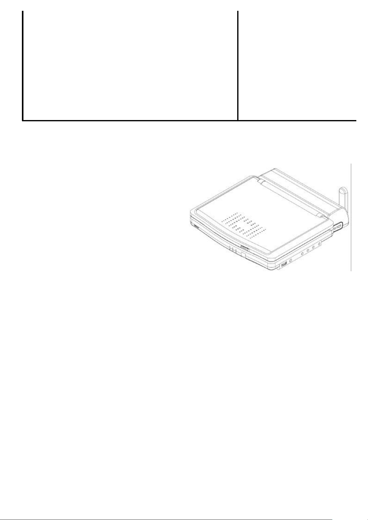
TFT PORTABLE DVB-T/DVD PLAYER
SUNSTECH PLF-77TD
SERVICE MANUAL
2006- PRINTED IN
R598MB
CAUTION: Before servicing the chassis, read the “IMPORTANT SERVICE SAFETY INFORMATION” section on
page 2 of this manual.
SPECIFICATIONS
l GENERAL SPECIFICATION
l 7” ACTIVE- MATRIX TFT TYPE.
l DVD, VCD, CD, CD-R, CD-RW, MP3, DIVX, HDCD
SUPPORTS.
l USB FUNCTION
l 16:9 / 4:3 PICTURE SELECT.
l HIGH BRIGHTENNESS.
l HIGH CONTRAST.
l WITH LOGO OPENING SCREEN.
l SLOW MOTION ½, 1/4, 1/8, 1/16
l F.B / F.F x2, x4, x8, x16 SPEED.
l ANGLE MENU.
l 20 TRACK PROGRAM FOR CD PLAYING.
l ZOOM x 2, 3, 4.
l REMOTE CONTROL.
l S. VIDEO OUTPUT (for Ext. TV Monitor)
l HEADPHONE OUT x 1.
l AUDIO OUTPUT 0.5W x 2/8 ohm.
l LONG BATTERY TIME OF OVER 2 HRS.
l DIMENSION :
212(L) x 170(W) x 4 30(H) mm(excluding battery)
l AC POWER SOURCE:
ADAPTER: 230V
l DC POWER SOURCE: BATTERY PACK: 7.2V
l FEATURES FOR DVB-T TUNER (FREE ON AIR)
l FREQUENCY RANGE :
VHF CH5 – CH12 (174MHZ – 230MHZ)
UHF CH21 - CH69 (470MHZ – 862MHZ)
l 1,000 PROGRAMMABLE FAVORITE CHANNELS
l 9 PICTURES FOR PROGRAM AUTO -SCAN
l EPG FUNCTION SUPPORT (TELE-TEXT OPTION)
l PROGRAM LIST WITH PROGRAM PREVIEW AFTER
TUNER POWER ON
l OSD TRANSPARENT ADJUSTMENT.
l FULL FUNCTION REMOTE CONTROL
CONTENTS
IMPORTANT SERVICE SAFETY INFORMATION................2
DISASSEMBLY FOR REPAIR .................................................3
WIRING DIAGRAM…………… ………………………....……4
BLOCK DIAGRAM....................................................................5
CIRCUIT DESCRIPTION .............................……………...6~14
PARTS LIST ..........................................…………............ 1 5~28
EXPLODED VIEW (CABINET) ............................................. 29
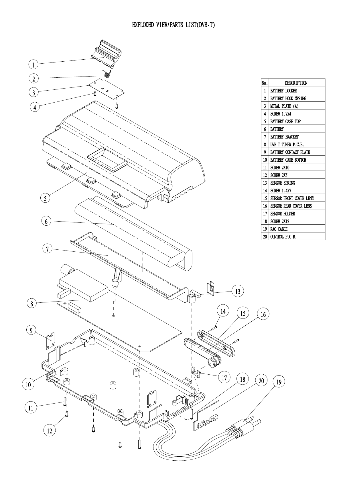
EXPLODED VIEW (DVB-T).................................................. 30
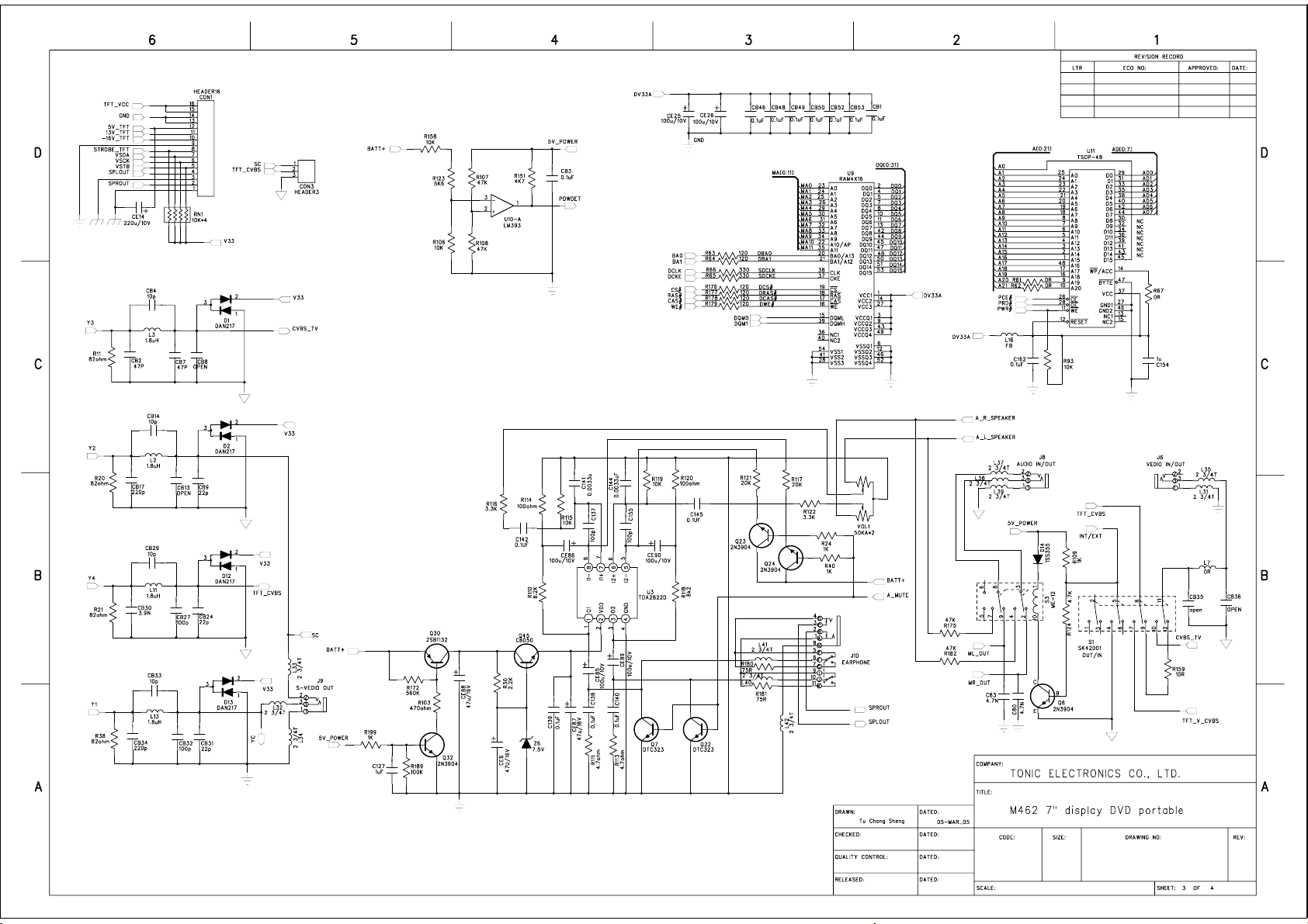
SCHEMATIC DIAGRAMS.................. ...............................31~39
PRINTED CIRCUIT BOARDS.......................................... 4 0~57
Note: Follows a policy of continuous advancements in development. For this reason specifications may be changed without notice.
1. SAFETY PRECAUTIONS
Before returning a unit to the customer, always make a safety check
of the entire unit, including, but not limited to the following items:
a. Be sure that no built -in protective devices are defective and/or have
been defeated during servicing.
(1) Protective shields are provided to protect to protect both the
technician and the customer. Correctly replace all missing protective
shields including any removed for servicing convenience.
(2) When reinstalling the chassis and/or other assemblies in the
cabinet, be sure to put back in place all protective devices, including, but
not limited to, nonmetallic control knobs, insulating fishpapers,
adjustment and compartment covers/shields and isolation resistor
capacitor networks. Do not operate this unit of permit it to be operated
without all protective devices correctly installed and functioning.
b. Be sure that there are no cabinet openings through which an adult
or child might be able to insert their fingers and contact a hazardous
voltage. Such openings include, but are not limited to, excessively wide
cabinet ventilation slots, and an improperly fitted and/or incorrectly
secured cabinet back cover.
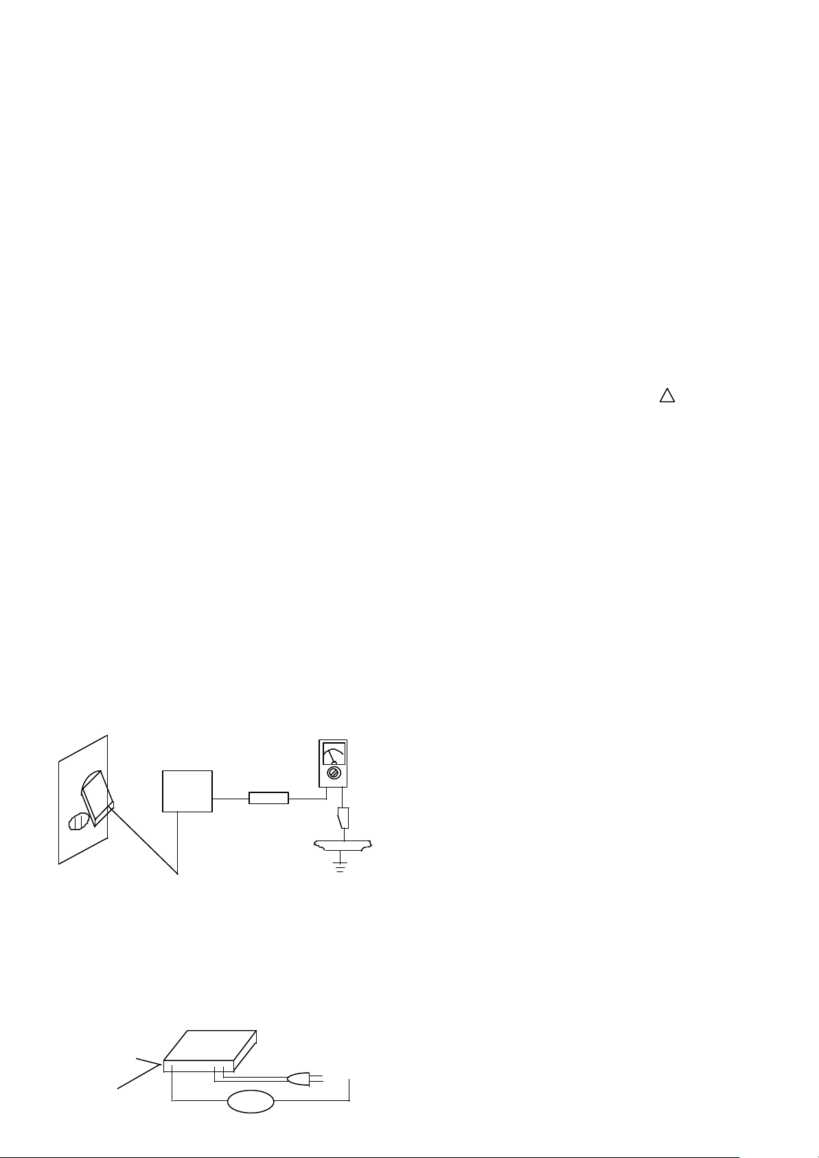
c. Leakage Current Hot Check - With the unit completely
reassembled, plug the AC line cord directly into a AC outlet. (Do not
use an isolation transformer during this test.) Use a leakage current
tester or a metering system that complies with American National
Standards institute (ANSI) C101.1 “Leakage Current for Appliances”
and Underwriters Laboratories (UL) 1410, (50.7). With the unit AC
switch first in the ON position and then in the OFF position, measure
from a known earth ground (metal water pipe, conduit, etc.) to all
exposed metal parts of the unit (antennas, handle bracket, metal cabinet,
screwheads, metallic overlays, control shaft, ect.), especially any
exposed metal parts that offer an electrical return path to the chassis.
Any current measured must not exceed 0.5 milliamp. Reverse the unit
power cord plug in the outlet and repeat test.
ANY MEASUREMENTS NOT WITHIN THE LIMITS SPECIFIED
HEREIN INDICATE A POTENTIAL SHOCK HAZARD THAT
MUST BE ELIMINATED BEFORE RETURNING THE UNIT TO
THE CUSTOMER.
AC LEAKAGE TEST
d. Insulation Resistance Test Cold Check
(1) Unplug the power supply cord and connect a jumper wire
between the two prongs of the plug.
(2) Turn on the power switch of the unit.
(3) Measure the resistance with an ohmmeter between the jumpered
AC plug and each exposed metallic cabinet part on the unit, such as
screwheads, antenna, control shaft, handle brackets, etc. When the
exposed metallic part has a return path to the chassis, the reading
ANTENNA
TERMINAL
2
EXPOSED
IMPORTANT SERVICE SAFETY INFORMATION
(READING
SHOULD
NOT BE
ABOVE
0.5mA)
EARTH
GROUND
METAL
PART
DEVICE
UNDER
TEST
TEST ALL EXPOSED
METAL SURFACES
2-WIRE CORD ALSO
TEST WITH PLUG
REVERSED (USING AC
ADAPTER PLUG A
REQUIRED)
OHMMETER
OM
LEAKAGE
CURRENT
TESTER
should be between 1 and 5.2 Megohm. When there is no return path to
the chassis, the reading must be “infinite”. If it is not within the limits
specified, there is the possibility of a shock hazard, and the unit must
be repaired and rechecked before it is returned to the customer.
2. PRODUCT SAFETY NOTICE
Some electrical and mechanical parts have special safety related
characteristics which are often not evident from visual inspection, nor
can be protection they give necessarily be obtained by replacing them
with components rated for higher voltage, wattage, etc. Parts that have
special safety characteristics are identified by a ¡I on schematic and
parts list. Use of a substitute replacement that does not have the same
safety characteristics as the recommended replacement part might create
shock, fire, and/or other hazards. Product Safety is under review
continuously and new instructions are issued whenever appropriate.
3. SERVICING PRECAUTIONS
CAUTION: Before servicing the unit covered by this service manual
and its supplements, read and follow the SAFETY PRECAUTIONS on
this page. NOTE: If unforeseen circumstances create a conflict between
the following servicing precautions and any of the safety precautions,
always follow the safety precautions. Remember: Safety First.
General Servicing Precautions.
a. Always unplug the unit’s AC power cord from the AC power
source before:
(1) removing or reinstalling any component, circuit board, module, or
any other unit assembly.
(2) disconnecting or reconnecting any unit electrical plug or other
electrical connection.
(3) connecting a test substitute in parallel whit an electrolytic
capacitor in the unit.
Caution: A wrong part substitution or incorrect polarity
installation of electrolytic capacitors may result in an explosion hazard.
b. Do not defeat any plug/socket B+ voltage interlocks with which
the unit covered by this service manual might be equipped.
c. Do not apply AC power to this unit and/or any of its electrical
assemblies unless all solid-state device heat sinks are correctly installed.
d. Always connect a test unit ground lead to the unit chassis ground
before connecting the test unit positive lead. Always remove the test
instrument’s ground lead last.
4. LASER PRECAUTIONS
WARNING!
1. When servicing (in case it is necessary to confirm Laser Beam
Emission), be sure not to place your eyes any closer than 1 ft or 30cm
from the surface of the Object Lens on the Optical Pickup Block.
HANDLING THE LASER PICKUP
2. Laser diodes are extremely susceptible to damage from static
electricity. Even if a static discharge does not ruin the diode, it can
shorten its life or cause it to work improperly. When replacing the
pickup, use a conductive mat on the floor and desk and wear a wrist

band connected to ground through a 1M ohm resistor to protect the
laser diode from static damage. If the lens should get dusty, blow off the
OF PROCEDURES HEREIN MAY RESULT IN HAZARDOUS
dust carefully from the object.
3. There are no adjustable parts in the pickup assembly. If it is
defective, replace the whole pickup assembly.
CAUTION:
USE OF CONTROLS, ADJUSTMENTS OR PERFORMANCE
RADIATION EXPOSURE.
DANGER:
IF INTERLOCK FAILS OR IS DEFEATED, THE LASER LIGHT
IS ABLE TO FUNCTION. THE LASER IS INVISIBLE, AVOID
DIRECT EXPOSURE TO BEAM.
3
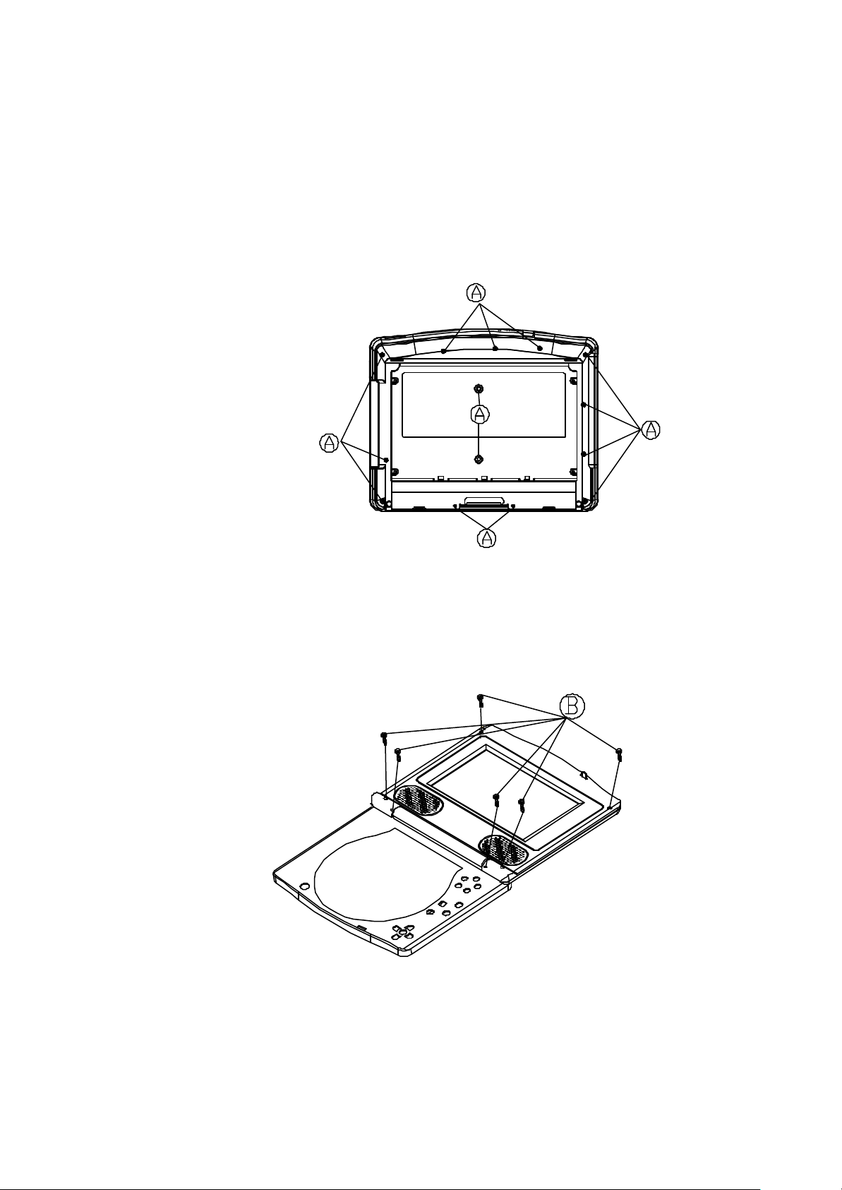
DISASSEMBLY FOR REPAIR
TO DISASSEMBLY THE BOTTOM METAL CABINET
1. Remove the 14 screws (A) from bottom metal cabinet.
TO REMOVE THE INNER PANEL
2. Remove the 6 screws (B) from the inner panel and out panel.
4
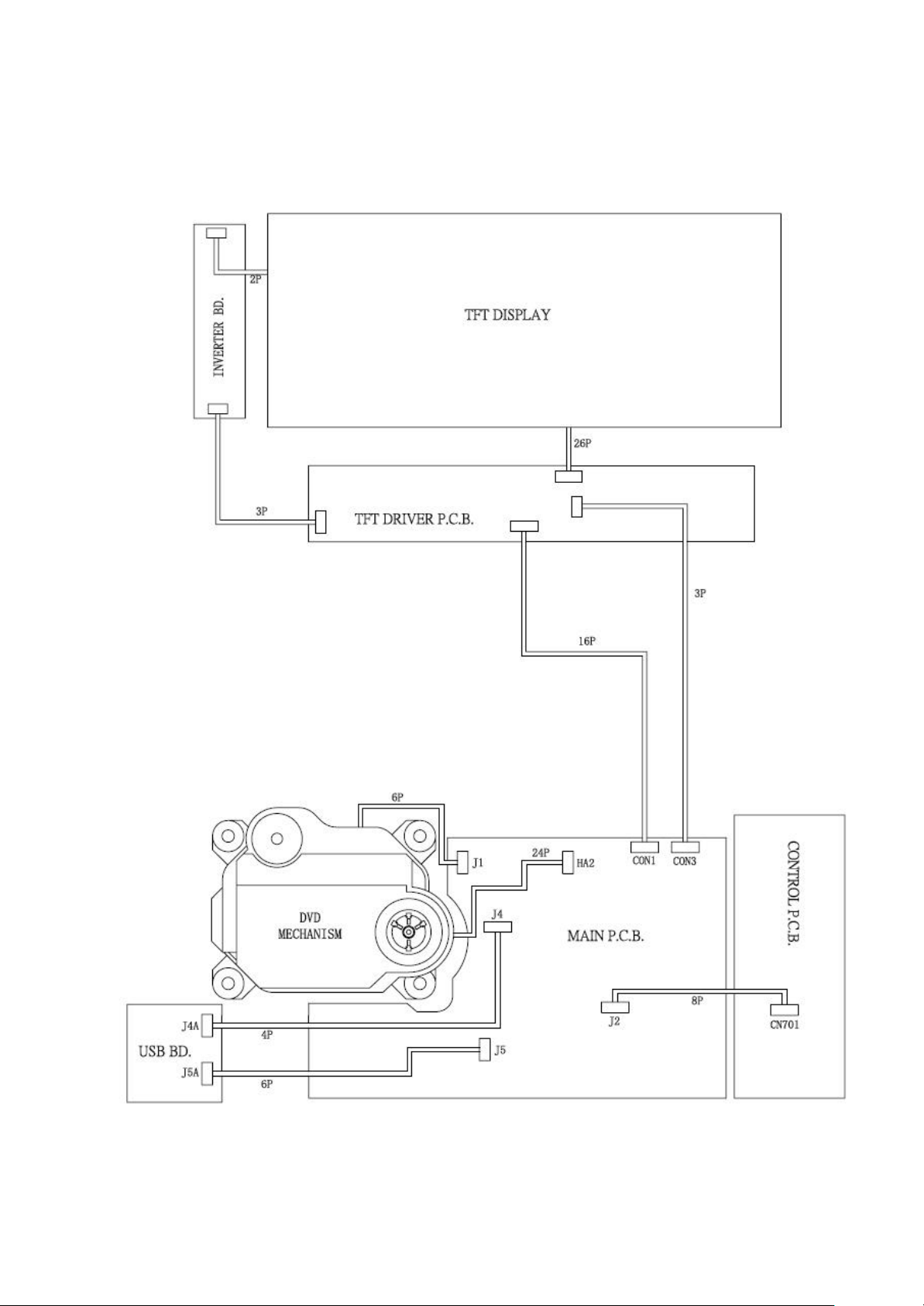
WIRING DIAGRAM
5
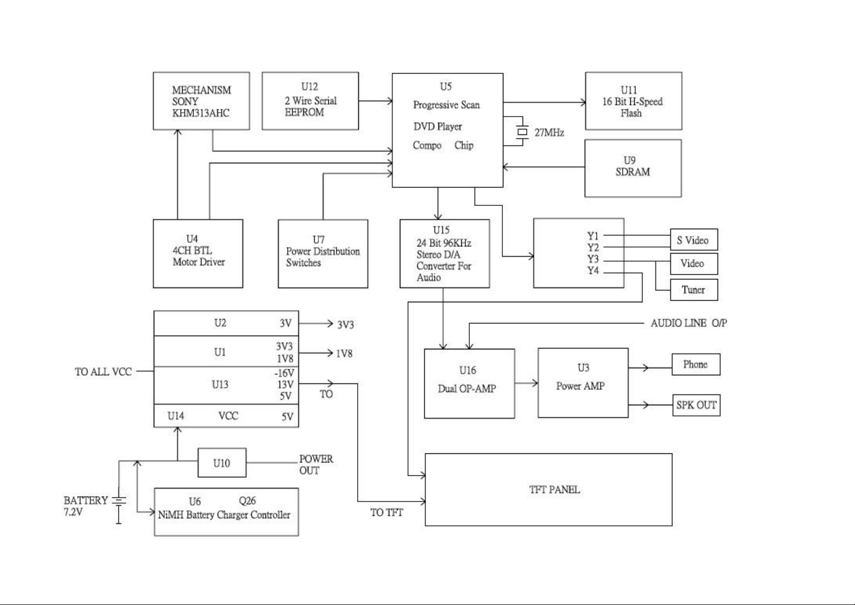
BLOCK DIAGRAM

CIRCUIT DESCRIPTION
100m? Power Distribution Switches: RT9701CB (U7)
NiMH BATTERY CHARGER CONTROLLER: LS2964S (U6)
Timer
LED
OSC
1
2
3
8
7
6
VDD
PWM
Vdet
GND
4
5
Idet
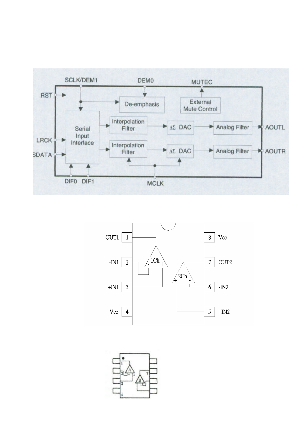
DUAL OPERATIONAL AMPLIFIER: RC4558D (U7,16)
A OUTPUT
1
8
V +
A -INPUT
A +INPUT
V -
2
3
4
7
B OUTPUT
6
B -INPUT
5
B +INPUT
6
CIRCUIT DESCRIPTION
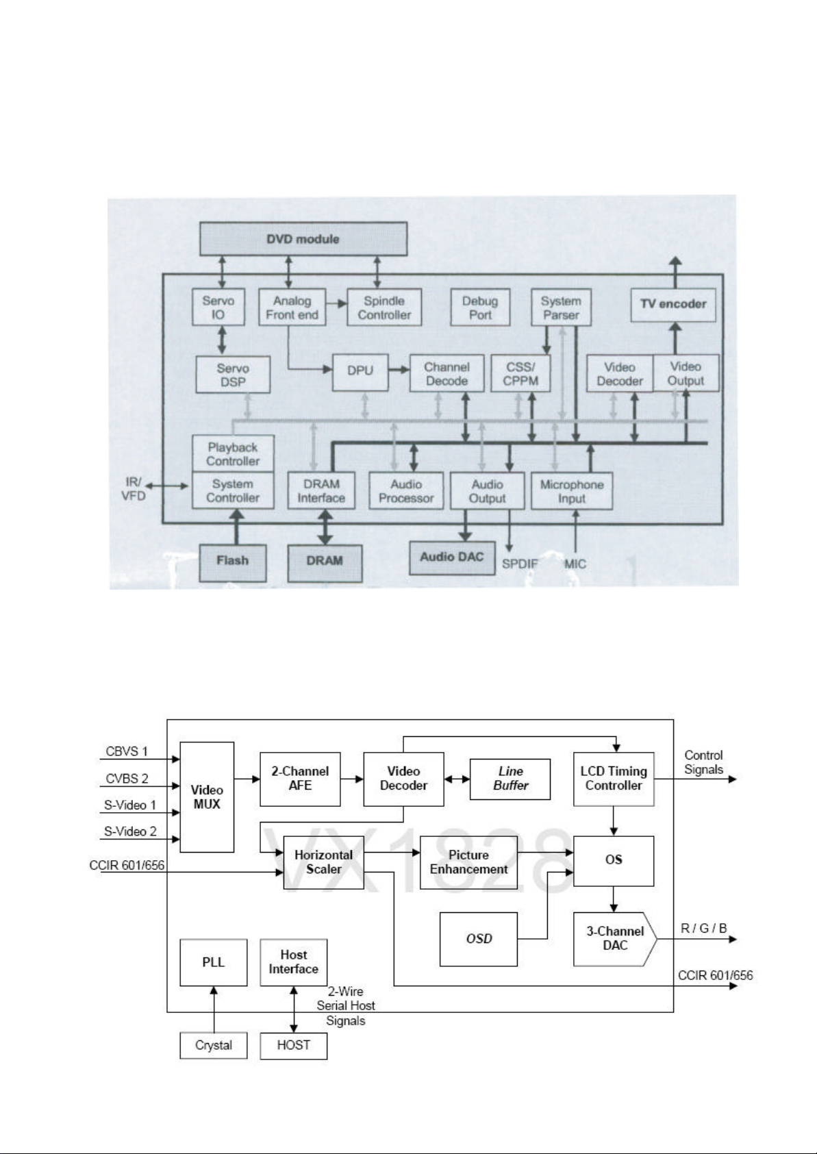
PROGRESSIVE SCAN DVD PLAYER COMBO CHIP: MT1389DE/B-L (U5)
VIDEO PROCESSOR FOR MIDDLE SIZE LCD PANEL: VX1828 (U1)
7
CIRCUIT DESCRIPTION
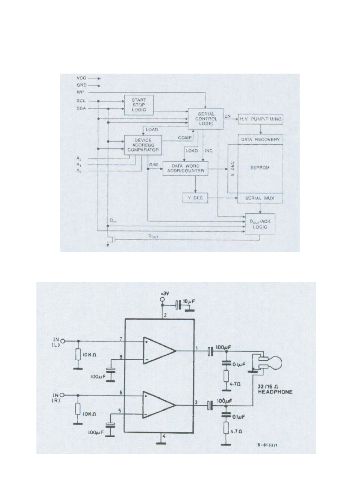
2-WIRE SERIAL EEPROM: AT24C02BN-10SU-1.8 (U6,U12)
DUAL LOW-VOLTAGE POWER AMPLIFIER: NJM2073M (U3)
8
CIRCUIT DESCRIPTION
24-BIT, 96 KHZ STEREO D/A CONVERTER FOR AUDIO: CS4340 (U15)
DUAL COMPARATORS: LM393DR (U10)
SINGLE-SUPPLY DUAL HIGH CURRENT OPERATIONAL AMPLIFIER: NJM3414AM-TE1(U3)
9

CIRCUIT DESCRIPTION
4-CHANNEL BTL MOTOR DRIVER FOR CD-ROM: AT5654H (U4)
300/500MA LOW DROPOUT LINEAR VOLTAGE REGULATOR: RP1101-19CXL( U1), RP110233CGL (Q2)
10
CIRCUIT DESCRIPTION
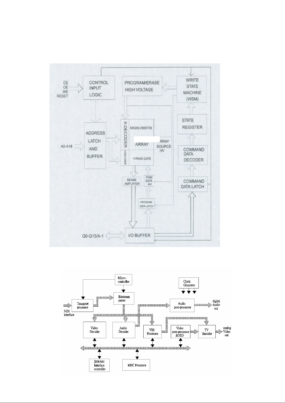
8M/16M-BIT CMOS SINGLE VOLTAGE 3V ONLY HIGH SPEED FLASH: AT49BV163A-70TU
(U11) , S29AL008D70TFI020 (U4)
DIGITAL TV STB BACKEND PROCESSOR: CT212T (U3)
11
CIRCUIT DESCRIPTION
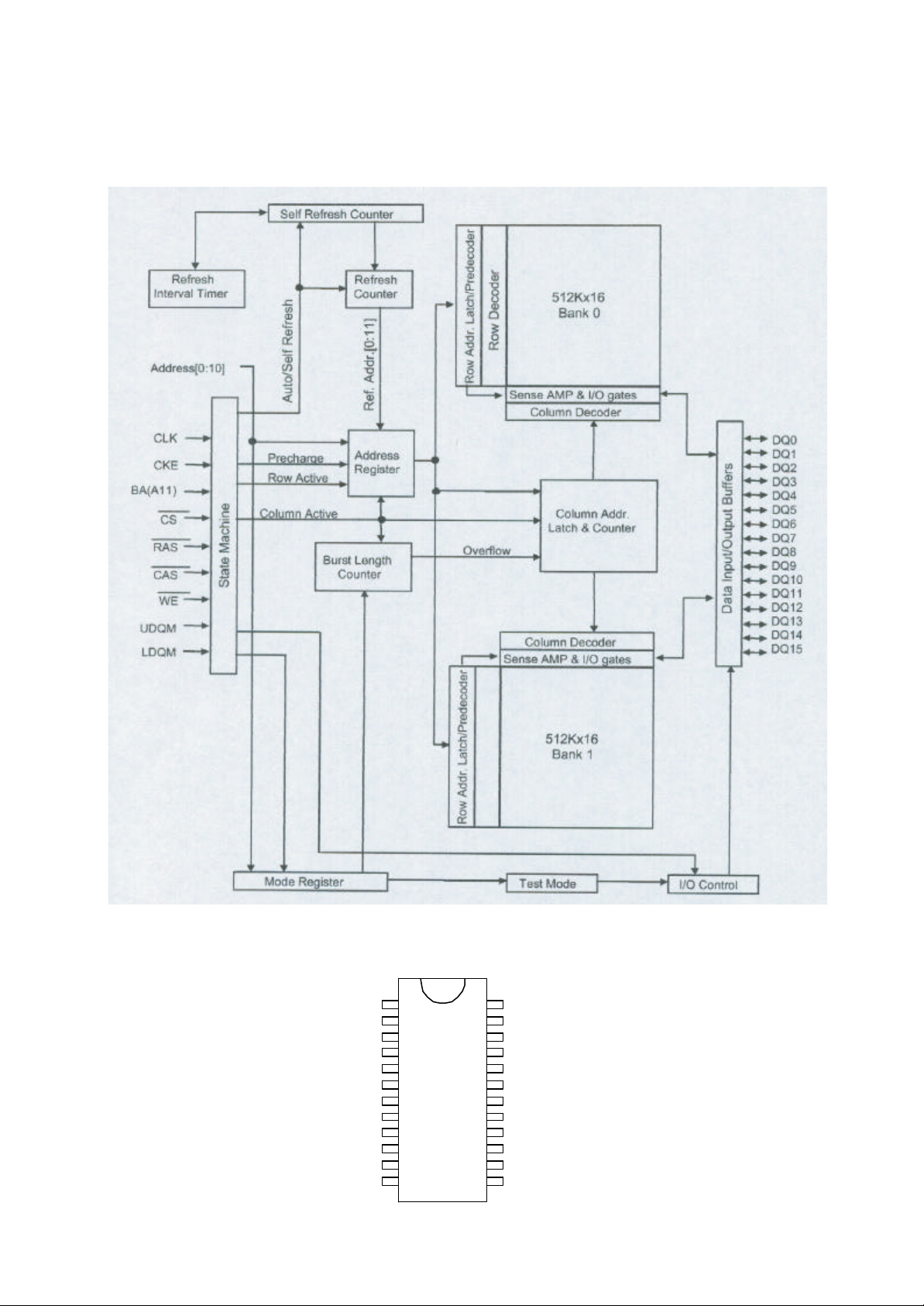
2 BANKS X 512K X 16 BIT SYNCHRONOUS DRAM : K4S641632H-UC75 TSOP-54 (U1,U9)
INFRARED REMOTE CONTROL TRANSMITTER : SC6122-001 (IC1)
KI
KI
KI
KI
KI
REM
V
DD
SEL
OSCO
OSCI
V
2
3
4
5
6
7
SS
1
2
3
4
5
6KI
7
8
9
10
12 13
24
23
22
21
20
18
17
16
15
1411
KI
KI
CCS
KI/O
KI/O
KI/O19
KI/O
KI/O
KI/O
KI/O
KI/O
LMP
1
0
0
1
2
3
4
5
6
7
12
CIRCUIT DESCRIPTION
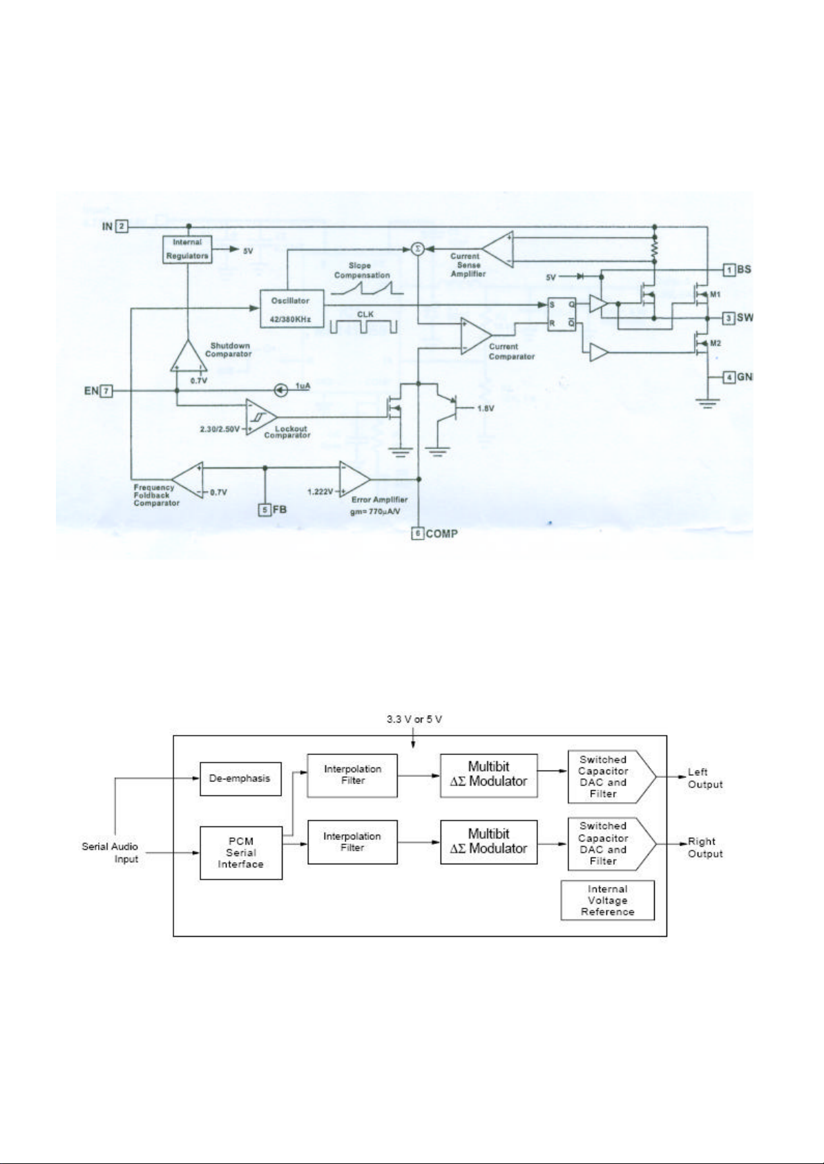
2A STEP DOWN DC TO DC CONVERTER: MP9141ES-LF-Z (U8, 9)
10-pin, 24-Bit, 192 kHz Stereo D/A Converter: CS4345 (U5)
13
CIRCUIT DESCRIPTION
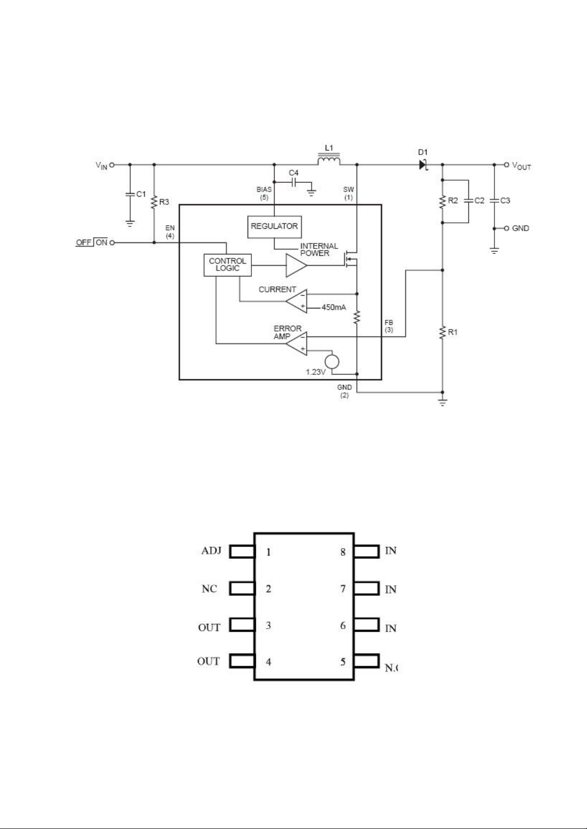
25V STEP-UP CONVERTER IC: MP1522ET (U1)
DIGITAL TV STB BACKEND PROCESSOR: B1117N-ADJ (U10)
14

N405M REMOTE CONTROL P.C.B.
20% 25V
1
5
Ref. No Parts No. Description QTY
2772M-STD-31 2772MB 120-230V VDE APP. STD
ASSY
059-05202-100-
102
HS-R598MB-GY-
410
001-04050-710
IC 1 002-06122-330 IC SC6122-001 (SILAN) SOP-24
Q1 003-24081-140 CHIP TRANSISTOR 2SC4081(RS)-
004-01122-600 INFRARED EMI TTING DIODES
R1 005-52109-301 CHIP RESISTOR 1 OHM +-5%
C2,3 006-72181-250 CERAMIC CHIP CAP 180 PF +-5%
C1 009-10476C510 ELECT CAP 47 UF +80%-20% 10V
X1 028-00455-011 CERAMIC FILTER ZTB455E
041-04051-002 N405 HANDSET BATTERY
041-04052-002 N405 HANDSET BATTERY
104-04050-0956 N405M H/S BOTTOM CAB.
111-04050-0956 N405M H/S BATTERY DOOR
125-04050-004 M593MB H/S
FOR HENDSET 144-11405-402 SCREW 1.4 X 5 KB 7
SW.ADAPTOR(SPEC
LIN)VDE:EN60065;W/M.I.C
SW0901500-W02(GP)
100~240V;TUV/CE;ROHS
R598MB H/S CHASSIS
W/COSMETIC ASSY(ROHS)
L.GY.MN C7-0 "SUNSTECH PLF77TD" (48 KEY)
(48 KEY) (ROHS)
(SMT) (ROHS)
TLB (ROHM) (ROHS)
EL-1L2 (ROHS)
(1608) (ROHS)
50V (1608) (ROHS) NPO
(ROHS) (PIN LENGTH 9MM)
(MEC) (2 PINS) (ROHS)
PLATE (+) (ROHS)
SPRING (-) (ROHS)
(L.GREY MN7-0) (ROHS)
(L.GREY MN7-0) (ROHS)
MEM.SW.PLATE(ROHS)W/RED
032C/ SIL.8001C/GN.375C
2X/SIL.GY.8403C/WH.SK.
Ref. No Parts No. Description QTY
1
R519MB -SIL-
1
127-04625-1974 R519MB POWER KNOB
127-04627-1974 R519MB PANEL OPEN KNOB
1
128-05180-0974 R519MB BUTTON 'A'
1
1
1
1
1
2
1
1
1
1
1
1
1
128-05181-0974 R519MB BUTTON 'B' (UP/DOWN)
128-05182-0974 R519MB BUTTON
128-05183-0974 R519MB BUTTON 'D' (SKIP
128-05184-0974
128-05185-0974 R519MB BUTTON 'F' (PLAY)
128-05189-0974 R519MB DISC.OPEN BUTTON
129-05180-000 M518 DOOR BRACKET;ROHS 2
129-05189-000 M518 DISC DOOR OPEN
M462-CAR-
001-35000-400 3500MC CAR BAT SUPPLY P.C.B.
D1-4 004-05401-300 RECTIFIER IN-5401 (ROHS) 4
R1 005-10152-314 RESISTOR 1.5 K +-5% 1/4W
C1 006-10203-550 CERAMIC CAP 0.02 UF +80%-20%
C2 009-10107-525 ELECT CAP 100 UF +80%-
D10 019-12000-110 L.E.D. DIAMETER 3MM(RED)
031-02600-040- JUMPER WIRE AWG22UL 60MM 1
KNOB
ADAPTOR-09
(D=2.5MM) ;ROHS
R519MB SILVER KNOB VERSION
ASSY(ROHS)
(SP.SIL.SS9-1/ABS) (ROHS)
(SP.SIL.SS9-1/ABS) (ROHS)
(LEFT/RIGHT) (ROHS)
(SP.SIL.SS9-1)
(ROHS) (SP.SIL.SS9-1)
'C'(SETUP/DIS./TITLE/MENU)
(SP.SIL.SS9-1) (ROHS)
F.F./F.R.) (SP.SIL.SS9-1) (ROHS)
R519MB BUTTON 'E' (STOP/PAUSE)
(SP.SIL.SS9-1) (ROHS)
(SP.SIL.SS9-1) (ROHS)
(SP.SIL.SS9-1) (ROHS)
BRACKET;ROHS
R598MB CAR ADAPTOR ASSY
(OUTPUT DC 9V,1.2A)
(ROHS)
(ROHS)
50V (ROHS)
(ROHS)
SEL-2110R (ROHS)
1
1
1
1
1
1
1
PARTS LIST
1
1
1
1
1
1
1
1
1
1

300
1
6
Ref. No Parts No. Description QTY
001 RED (ROHS)
031-10500-100-
001
043-20192-
050-05020-201 2A/250V GLASS FUSE 5X20 FAST
101-97030-010 9703 CAR ADAPTOR FRONT
102-97030-010 9703 CAR ADAPTOR REAR
105-97030-010 9703 CAR ADAPTOR CAP
133-97031-311 GT9839 (9703) CAR ADAPTOR
133-97035-304 9703 CAR ADAPTOR SPRING
133-97036-352 9703 CAR ADAPTOR PLUG
FOR CAR ADAPTOR
FRONT CABINET
20MM X 1(D5) 202-10005-002 TINNED CCS WIRE (DIA.
R572M-DVD-
MAIN PCB (J1) TO
LOADER
037-45251-245 24P FILM CABLE 5+250+5 UL
FOR LOADER 145-69912-100 PVC WASHER W/HOLE (L=9MM
160-00313-001 DVD MECHANISM SONY
144-12608-111 SCREW 2.6 X 8 RT (BLACK)
LOADER
025-10006-149 6P J.WIRE #30UL 100MM (2P
JUMPER WIRE AWG22UL 50MM
BLACK(ONE SIDE 4MM,ONE
SIDE 10MM) (ROHS)
T409 DC CORD 75"#20 WH/BLK
(2P)W/BUSHING &DC PLUG
(Y001-D19102C458505Q)(Y.C.)
(ROHS)
ACTING;ROHS BUSSMANN/S500
UR/VDE/SEMKO/IMQ/BSI APP.
CABINET (BLACK) (ROHS)
CABINET (BLACK) (ROHS)
(BLACK) (ROHS)
SPRING PLATE T=1.0MM (ROHS)
T=0.4MM (ROHS)
(GENERAL TECHNIC) (ROHS)
(ROHS)
0.0000
0.5MM);ROHS (TIN PLATE WIRE
W/STEEL)
R572M LOADER (SONY
KHM313AHC) SUBASS'Y
2MM) JST;ROHS
(P=0.5MM) (ROHS)
W=6.5MM T=1MM DIA.=3.3MM)
(ROHS)
KHM313AHC (ROHS) (SLIM
1
1
1
1
1
1
1
1
1
4
65
1
1
1
2
1
Ref. No Parts No. Description QTY
TYPE/BALL CLAW)
161-03102-001 KHM-310 INSULATOR
(IIR,HARDNESS=40 DEG)
(SILICON RUBBER) ;ROHS
M519M-
CASING -02
029-02808-202-
001
FOR LCD GROUNDING 039-30005-000 SOLIDING LUG 5.5MM (DIA.
041-04621-002 M462 BATTERY CONTACT
041-04622-002 M462 BATTERY CONTACT
041-04623-002 M462 BATTERY PLATE SPRING
049-00706-009 TFT DISPLAY AT070TN07 V.A
129-04629-010 M462 BATTERY CONTACT
129-04629-110 M462 BATTERY CONTACT
129-04629-210 M462 DISC DOOR OPEN SWTICH
130-04624-110 M462 DISPLAY ADAPTOR RING
133-04099-302 T409 HOOK SPRING (ROHS) 1
133-04621-115 M462 METAL PLATE (D) (IRON)
133-04623-115 M462 METAL BRACKET (A)
133-04623-125 M462 METAL BRACKET (B)
FOR CD DOOR SW. X 1 133-04624-306 M462 SW. SPRING (ROHS) 2
M519M CASING ASSY (W/04900706-007) (ROHS)
28MM SPEAKER 8 OHM
NOR.:0.5W;MAX.:1W BLK
CLOTH ON BACK (SMDC
NO.:DS28-39) (ROHS)
1.7MM) ;ROHS
PLATE (+);ROHS
PLATE (-);ROHS
(+/-);ROHS
(INNOLUX);ROHS (7" TFT-LCD
MODULE W/O LED DRIVER BD.)
BRACKET (L)
(BLACK/POM) ;ROHS
BRACKET (R)
(BLACK/POM) ;ROHS
ADAPTOR (BLACK/POM) ;ROHS
(BLACK/POM) (ROHS)
(T=1.5 MM) (ROHS)
(IRON) (T=1.5 MM) (ROHS)
(IRON) (T=1.5 MM) (ROHS)
4
1
2
1
1
1
2
1
1
1
1
1
1
1
1

RUBBER 6 X 10 X 12MM (W/TWO
090)
(SP.MATT.BLACK)
1
7
Ref. No Parts No. Description QTY
FOR TFT SW. X 1
133-04625-360 M462 METAL PIN(A)
(STEEL)(DIA.=6 MM) (ROHS)
FOR BATTERY LOCK 133-04626-103 M462 METAL PLATE (A) (IRON)
(T=0.3 MM) (ROHS)
FOR BOTTOM CAB. 133-04629-305 M462 BATTERY PLATE SPRING
FOR BOTTOM CAB. (ROHS)
FOR MAIN P.C.B.
GROUNDING X 1
FOR CONTROL P.C.B.
GROUNDING X 1
FOR P.C.B. GROUNDING 133-04629-305-
133-05189-305-
133-05589-306 R558 CD DOOR SPRING
FOR BOTTOM CAB. 136-10015-480 RUBBER FOOT (DIA.4.8X1.5) MM
FOR BOTTOM CAB. 136-10020-480 RUBBER FOOT (DIA.4.8X2)MM
FOR BOTTOM BATTERY
CAB. USE
FOR BATTERY USE 136-10530-100 RUBBER 10 X 5 X 3MM (W/ONE
FOR 7" TFT USE 136-10540-100 RUBBER (10*5*4)MM W/ONE
FOR BATTERY SET 136-11501-200 RUBBER 20 X 15 X 1.5MM
FOR BATTERY SET 136-21060-120
FOR 24P FLAT WIRE ON
LOADER
FOR TFT FRONT CAB. 136-80020-040 PANEL RUBBER FOOT
138-04624-010 M462 DISC DOOR HOOK
FOR TFT FRONT CAB. 144-11405-201 SCREW 1.4X5 TB SILVER;ROHS 2
144-11706-402 SCREW 1.7X6 KB;ROHS 12
133-04629-303 M462 P.C.B. SPRING (B) (STEEL
T=0.3)MM(ROHS)
M462 P.C.B. SPRING (A) (STEEL)
002
001
136-10510-050 RUBBER 5 X 5 X 1MM (W/ONE
136-21503-200 RUBBER 15 X 2.5 X
(DIA.=0.5) (ROHS)
M518M DOOR BRACKET SPRING
(DIA.=0.5MM) (ROHS)
(T=0.6MM) (STEEL) (ROHS)
W/ONE SIDE TAPE (ROHS)
W/ONE SIDE TAPE (ROHS)
SIDE TAPE) (ROHS)
SIDE TAPE) (ROHS)
SIDE TAPE (ROHS)
(W/ONE SIDE TAPE) (ROHS)
SIDE TAPE) (ROHS)
20MM(W/TWO SIDE TAPE)
(ROHS)
(DIA.3.6X2.2)MM (GREY) (ROHS)
(BLACK/POM) ;ROHS
1
1
2
2
1
1
1
1
1
2
4
2
4
1
1
2
1
Ref. No Parts No. Description QTY
FOR BATTERY CAB. 144-11706-412 SCREW 1.7X6 KB (BLAC K) ;ROHS 3
FOR TFT SPRING USE 144-12004-511 SCREW 2X4 CWB (BLACK)
HARDEN (D=5MM
T=0.5MM)(E6D8011-0) ;ROHS
FOR DOOR BRACKET 144-12006-300 SCREW 2*6 PWT (A);ROHS 1
FOR HINGE SHAFT 144-12606-111 SCREW 2.6X6 RT (BLACK) ;ROHS 1
FOR DISPLAY 144-21702-201 SCREW 1.7X2 BM;ROHS 1
144-52005-122 SCREW 2X5 STR (TB)
SILVER;ROHS
FOR BOTTOM CAB. 144-52008-112 SCREW 2X8 STR (TB)
BLACK;ROHS
FOR BOTTOM CAB. 144-52010-112 SCREW 2*10 STR (TB) BLACK
(SFBPN20100SM) (ROHS)
145-24620-000 M462 METAL WASHER (A)
(IRON) (T=1.0 MM) (ROHS)
FOR TFT FRONT CAB.
FOR TOP CAB. X 1
M593MB-
103-05930-001 M593MB BATTERY CASY TOP
104-05930-001 M593MB BATTERY CASE
117-05930-0618 M593MB SENSOR FRONT COVER
117-05931-0618 M593MB SENSOR REAR COVER
FOR TUNER-KEY P.C.B. 125-04092-003 T409 X'FORMER PC CUT SHEET
129-05933-010 M593MB SENSOR HOLDER
129-05939-010 M593MB BATTERY BACKET
130-55268-040 M526MB BATTERY LOCKER 1
146-50409-001 T409 MAGNET (NDFEB)
X 1
BATT-ASSY-02
20X3.5X5MM "SMDC" (ROHS)
R598MB DVD BATTERY PACK
CHASSIS ASSY (W/998-00000-
(ROHS)
(BLACK/ABS)
W/SIL.877C SK. ;ROHS
BOTTOM (BLACK/ABS) (ROHS)
LENS (DARK SMOKY
801691/ABS) (ROHS)
LENS (DARK SMOKY
801691/ABS) (ROHS)
(35X22X0.5)MM(ROHS)
(BLACK/ABS) (ROHS)
(BLACK/ABS) (ROHS)
10
2
6
2
7
2
1
1
1
1
1
1
1
1

FOR CD DOOR BRACKET
1
8
PARTS LIST
Ref. No Parts No. Description QTY
(BLK./ABS) (SP.MATT.BLK.)
(ROHS)
133-04629-306-
001
133-05939-306 M593MB SENSOR SPRING
144-11704-411 SCREW 1.7X4 KT (BLACK) ;ROHS 2
FOR SENSOR COVER 144-51407-110 SCREW 1.4*7 STR (TA)
FOR BOTTOM CAB. 144-52005-112 SCREW 2X5 STR (TB) BLACK
FOR BOTTOM CAB. 144-52010-112 SCREW 2X10 STR (TB) BLACK
FOR BOTTOM CAB. 144-52012-112 SCREW 2*12 STR (TB)
998-00000-090 EPT NI-MH RECH.BATT. 7.2V
R598MB-C-0410 R598MB DVD "SUNSTECH"
103-05180-902 R598MB TOP CAB(INJ.GY.MN7-
104-04623-903 M526MB BOTTOM
108-04622-9410 M526 INNER P."SUNSTECH"
108-05180-9410 R598 OUTER
113-05180-004 R598 DVD DOOR
M462 BATTERY HOOK SPRING
(BLACK/STEEL) (DIA.=0.6MM)
(ROHS)
(DIA.:0.6MM) (ROHS)
BLACK;ROHS
(SFBPN205R0SM) ;ROHS
(SFBPN20100SM) ;ROHS
BLACK;ROHS
1500MAH (ROHS) EPT50AA150H6S;2P 120MM
WIRE+JST-XHP-2P
COSMETIC ASSY SPRAY
MATT.BLACK COLOR (ROHS)
0/ABS) (EMI.SP. SIL.SS9-1)
W/D.GY.433C/ENTER(W/USB)RO
HS
CAB.(INJ.BLK./ABS) (W/USB)
ROHS (EMI SP.MATT.BLK.)
W/SIL.877C/AV IN/OUT
(INJ.L.GY.MN7-0) (EMI SP.SIL.SS91/MATT.BK.)426C SK;ROHS
PANEL"SUNSTECH"(INJ.GY.MN7
-0/ ABS)(EMI.SP.SIL.SS9-
1)W/D.GY.433C (ROHS)
(INJ.GY./ABS#PA-777D)
Ref. No Parts No. Description QTY
ROHS(SP.SIL.SS9-1)
W/D.GY.433C(DIVX/DVBT)SK.
1
1
2
3
2
3
2
1
1
1
1
1
1
117-04620-0931 M462 SENSOR LENS (SEMI -
TRANS.WHITE/PMMA) ;ROHS
117-04621-0931 M462 LED LENS (SEMI -
TRANS.WHITE/PMMA) ;ROHS
130-04624-1887 M518MB DISPLAY SWITCH
ADAPTOR (L.GREY MNC7-
0/POM);ROHS
FOR FRONT CAB X 2
X 2
FOR BOTTOM CAB. X 2
FOR ME TAL PLATE X 1
FOR TFT RING X 1
180-04624-010 M462 METAL BOTTOM
R598MB-P-0410 R598MB DVD "SUNSTECH PLF-
015-80593-001 M593 DVB-T ANTENNA TQJ-V/U -
043-26102-541 1P RCA CABLE #26UL 1M (2 SIDE
043-26102-542 2P RCA CABLE #26UL 1M (2P
FOR BATTERY BOTTOM 136-70010-100 RUBBER FOOT (DIA.10X1)MM
998-00000-093 BATTERY CR2025 3V
MI-M598MB-
MI-04620-100-15 R598MB (MI) DVD MAIN 1
144-12005-401 SCREW 2X5 KT;ROHS 4
144-12005-411 SCREW 2X5 KT (BLACK) ;ROHS 4
CABINET (BLACK) ;ROHS
77TD" PACKING TO GERMANY
(ROHS)
BT4 (BOBOTO) VHF174-
230/UHF470-862MHZ;ROHS
RCA PLUG) YELLOW (Y001-
D100U182549B) (YIP
CHUN) ;ROHS
SIDE RCA PLUG) WHITE/RED
(Y001-D10025622637A49B)
(Y.C.) ;ROHS
NITTO 500 TAPE MATERIAL:
PORON #HH48C;ROHS
(YUFENG);(ROHS)
R598MB (MI) DVD
001
MAIN/CONT/TUNER BD. ASSY
(W/LINE SELECT) (ROHS)
1
1
1
1
1
1
1
1
2
1
1

3P #30UL D.SHIELD WIRE 220MM
4P #28UL D.SHIELD WIRE 200MM
19
Ref. No Parts No. Description QTY
BD.CHASSIS ASSY (W/LINE
SELECT SWITCH)(FOR
KHM313AHC)
Q37 003-03906-100 TRANSISTOR 2N3906
(MOTOROLA) (PNP TO-92)
Q45 003-08050-393 TRANSISTOR 8050C (KEC) 1
R200 005-10121-314 RESISTOR 120 OHM +-5% 1/4W
(ROHS)
CE14 009-10477-510 ELECT CAP 470 UF +80%-20% 10V
(ROHS)
CE3,7,9,10,19,46,63,70,71,77
97,98,103, 105,107
CE1,11,12,26,45,47,83,85,86,
89,90
CE2,4,5 009-30107-416 ELECT CAP 100UF +-20% 16V (SS
CE62,73 009-30227-410 ELECT CAP 220 UF +-20% 10V (SS
CE52,57 009-30475-450 ELECT CAP 4.7 UF +-20% 50V (SS
CE8,16,17,18,21,22,58 009-30476-410 ELECT CAP 47 UF +-20% 10V (SS
CE6,87,88 009-30476-416 ELECT CAP 47 UF +-20% 16V (SS
CE13,20,23,25,125,126 009-69107-406 ELECT CAP 100 UF +-20% 6.3V
CE24 009-80107-410-
VOL1 010-20103-161 ROTARY VOL. R1016G21B1-A10K
L40,41 015-00003-101 CHOCK COIL 2 3/4 T NO.:R0157-
L32,34,37,38 015-00011-001 TOROID COIL R142-880928 11T
L19 015-00100-506 CHOKE COIL 10 UH DIA.6
L18 015-00150-106 CHOKE COIL 15 UH DIA.6 1
009-30106-425 ELECT CAP 10 UF +-20% 25V (SS
4X7) (ROHS)
009-30107-410 ELECT CAP 100 UF +-20% 10V (SS
5X7) (ROHS)
6.3X7) (ROHS)
6.3X7) (ROHS)
4X7) (ROHS)
4X7) (ROHS)
5X7) (ROHS)
(SM 5X5) (ROHS)
ELECT CAP 100 UF +-20% 10V
C02
(CEC) LF TAPING 5MM
(K101MBPN0507O) 5*7 (ROHS)
(DOUBLE) 10KA (SAME
PROPIT) ;ROHS
CB33-858688 (ROHS)
(COILS) (ROHS)
(RADIAL TYPE) (CW65-100K)
(ZHONGSHAN) ;ROHS
15
11
Ref. No Parts No. Description QTY
(RADIAL TYPE) (CW65-150K)
(ZHONGSHAN) ;ROHS
L30 015-00331-106 CHOCK COIL 330 UH (CW45-
1
L1,4,15,17 015-00470-106 CHOKE COIL 47 UH DIA.6
1
D25 019-12000-304 LED 3MM (RED) 304H (EVER
1
D22,23 019-15000-340 L.E.D. DIAMETER 3MM (GREEN)
SW1 020-12203-151 SWITCH SK-22D03-VG3 (NS)
S1 020-14204-112 SWITCH SK-42D01EG4 (SEE-
3
S5,6 020-31100-061 DETECTOR SWITCH SPPB512300
2
J9 021-23505-101 STEREO JACK EJS-3-0935B
2
J10 021-23505-106 STEREO JACK ST-35072-02 (SEE-
7
J8 021-23505-107 ST.P/H JACK ST-3531HW
3
6
1
1
2
4
1
J6 021-23506-105 STEREO JACK ST-3531HY (SEE-
J7 021-34503-101 DC JACK 3PINS (DC-014)
MAIN PCB (CON3) TO
TFT PCB (YC)
MAIN PCB (J4) TO USB
BD. J4A
MAIN PCB (J5) TO USB
BD. J5A
MAIN PCB (CON1) TO
TFT PCB (XS03)
J4A 025-20004-109 4P WAFER H-TYPE (1.5MM
025-10003-148
025-10004-154
025-10006-155 6P #28UL J.WIRE 150MM (2P
025-10016-009 16P UL J.WIRE #32*16 230MM (2P
331K) (RADIAL TYPE) ;ROHS
(RADIAL TYPE) (CW65-470K)
(ZHONGSHAN) ;ROHS
CHANNEL) (ROHS)
L-34GDLK KINGBRIGHT(ROHS)
(SEIKO) ;ROHS
PLUS) ;ROHS
(ALPS) ;ROHS
(DAIICHI) BLACK(ROHS)
PLUS) BLACK(ROHS)
(WHITE) (5 PINS) (SEE-PLUS)
(ROHS)
PLUS) YELLOW (ROHS)
SEIKO;ROHS
(2P 1.25MM) JS-1146-03*2
(KARSON 920-333-00) ; ROHS
(2P 1.5MM) (ROHS)
1.5MM) JST (WHITE) ;ROHS
1MM) JST SHR-16V -S-B*2
(HOUSING +/-);ROHS
PITCH) JST(ROHS)
1
4
1
2
1
1
2
1
1
1
1
1
1
1
1
1
1

JUMPER WIRE AWG22UL 150MM
JUMPER WIRE AWG22UL 240MM
JUMPER WIRE AWG26UL 150MM
8P F.WIRE #28UL/2561 120MM (1P
Ref. No Parts No. Description QTY
J4 025-20004-214 4P WAFER V-TYPE (1.5MM
PITCH) (ROHS)
J1 025-20006-102 6P WAFER H-TYPE (2MM PITCH)
JST(ROHS)
J5A 025-20006-108 6P WAFER H-TYPE (1.5MM
PITCH) JST(ROHS)
J5 025-20006-208 6P WAFER V -TYPE (1.5MM
PITCH) W150V06T00(ROHS)
L35 027-00000-004 FERRITE BEAT CORE (RH-
3.5X6X1.0) (COILS NO.: 707866)
AXIAL TYPE (ROHS)
BATT.PLATE SPRING(+)
TO MAIN BD.BATT(+)
BATT.PLATE SPRING(-)
TO MAIN BD BATT(-)
FOR 7" DISPLAY 032-10151-040-
DISPLAY PCB (R+) TO RSPEAKER (+)
DISPLAY PCB(L+) TO
SPEAKER(+)
DISPLAY PCB(L -/R-) TO
SPEAKER(-)
USB1 046-80400-004 M560 USB CONNECTOR 4P USB
Y1 052-27000-000 CRYSTAL: 27MHZ AT -49 TYPE
J3 061-06038-001 INFRARED REMOTE DETECTOR
5MM * 1 CE15 202-10005-002 TINNED CCS WIRE (DIA.
20
MI-04620-700 M462MB (MI) DVD CONT.BD.
001-05180-700 M518MB CONTROL P.C.B.
CONTOR PCB (CN701) 025-10008-090
031-02151-040-
001
031-10241-040-
001
001
033-03700-030-
001
033-04700-030-
001
033-10700-030-
001
RED(ROHS)
BLACK(ROHS)
BLACK(ROHS)
JUMPER WIRE AWG28UL 70MM
ORANGE(ROHS)
JUMPER WIRE AWG28UL 70MM
YELLOW(ROHS)
JUMPER WIRE AWG28UL 70MM
BLACK(ROHS)
AF 90 (WHITE)G -AUASW204GX
(ALRIGHT) ROHS
(MEC) +-50PPM;ROHS
FM-6038LM(ROHS)
0.0000
0.5MM);ROHS(TIN PLATE WIRE
W/STEEL)
CHASSIS ASSY
(T=1MM) (138*35)MM (ROHS)
1.27MM) JS-1146-08 (KARSON
1
1
1
1
1
1
1
1
1
1
2
1
1
1
38
1
1
1
Ref. No Parts No. Description QTY
920-336-00) ;ROHS
048-10006-002 6MM CONNECTION PLATE
(200G) (W/LEAD) (ROHS)
MI-05930-100-02 M593 (MI) DVB-T TUNER BOARD
CHASSIS ASSY (ROHS)
EC10 009-30105-450 ELECT CAP 1 UF +-20% 50V (SS
4X7) (ROHS)
EC11,12,18,19,29,30 009-30106-425 ELECT CAP 10 UF +-20% 25V (SS
4X7) (ROHS)
EC1,2,3,4,8,13,14,15,16,17,22
,25
EC20,24 009-30107-416 ELECT CAP 100UF +-20% 16V (SS
EC32 009-30226-416 ELECT CAP 22 UF +-20% 16V (SS
EC27 009-30227-410 ELECT CAP 220 UF +-20% 10V (SS
EC21,23,26,28 009-30227-416 ELECT CAP 220 UF +-20% 16V (SS
EC31 009-30335-450 ELECT CAP 3.3 UF +-20% 50V (SS
EC5,6,7,9 009-30476-410 ELECT CAP 47 UF +-20% 10V (SS
LED1 019-35000-113 LED 2X5MM L -113GDLK (GREEN)
FOR J12 025-10002-204 2P J.WIRE #20UL 220MM (1P
025-10004-168 4P RAC CABLE 400MM (2P
J10,11,12 025-20002-204 2P WAFER V -TYPE (2.5MM
J3 025-20004-202 4P WAFER V -TYPE (2MM PITCH)
J2 025-20008-203 8P WAFER V -TYPE (2MM PITCH)
FOR DVB-T TUNER PCB
(RED) & BATT (+) *1
FOR DVB-T TUNER PCB
009-30107-410 ELECT CAP 100 UF +-20% 10V (SS
5X7) (ROHS)
6.3X7) (ROHS)
4X7) (ROHS)
6.3X7) (ROHS)
6.3X7) (ROHS)
4X7) (ROHS)
4X7) (ROHS)
KINGBRIGHT(ROHS)
2.5MM) JST (RED/BLACK);ROHS
2MM)JSY A2001H-4P (3.5MM
PLUG*2 MOND & ST.+4P
R/W/GND/Y) ;ROHS
PITCH) JST(ROHS)
JST (ROHS) (B4B-PH-K-S)
JST(ROHS)
027-13060-080 TOROID CORE
(12.70*6.35*7.90)MM (COILS
NO.:M191206079CL5) (ROHS)
14
1
1
6
12
2
1
1
4
1
4
1
1
1
3
1
1
2

JUMPER WIRE AWG22UL 220MM
JUMPER WIRE AWG22UL 150MM
2
1
Ref. No Parts No. Description QTY
(BLK) & BATT (-) *1
DVB-T TUNER PCB TO
BATT (+)
DVB-T TUNER PCB TO
BATTERY (-)
031-02221-040-
001
031-10151-040-
001
RED(ROHS)
BLACK(ROHS)
XTAL1 052-27000-000 CRYSTAL: 27MHZ AT -49 TYPE
(MEC) +-50PPM;ROHS
U2 061-00404-002 DVB-T TUNER DNOS404PH104A
(SAMSUNG) (HORIZONTAL
MOUNT TYPE/DIN-JACK);ROHS
30MM*5 (FOR SHIELD
PLATE TO GND)
202-10005-002 TINNED CCS WIRE (DIA.
0.5MM);ROHS (TIN PLATE WIRE
W/STEEL)
MI-05930-700-01 M593 (MI) DVB CONTROL
P.C.B.CHASSIS ASSY
001-05930-700 M593 CONTROL P.C.B. (94HB)
(22*40*1.6)MM "CHEERTEK"
T212(ROHS)
R1,2 005-10100-306 RESISTOR 10 OHM +-5%
1/16W(ROHS)
C1 009-30107-410 ELECT CAP 100 UF +-20% 10V (SS
5X7) (ROHS)
SW1 020-22204-106 SWITCH SS-22F04 (2P2T) (SEE-
SPLUS) (ROHS)
K1,2 020-31100-058 TACT SWITCH TC -00104C-00
(SEE-PLUG) (ROHS)
FOR INFRARED REMOTE 025-10003-066C 3P J.WIRE #26UL 120MM (1P
2MM) JST
CONTROL PCB (CN1) TO
DVB-T TUNER PCB(J2)
025-10008-019 8P FLAT WIRE 190MM (1 PLUG
2MM) JST;ROHS
061-00138-003 INFRARED REMOTE CONTROL
RECEIVER MODULE HT138BS
(MOBICON) 38KHZ;ROHS
135-05932-201 M593 COPPER SHEET-02
(80*78*0.1)MM;ROHS (1 SIDE
W/TAPE & COATING PAPER)
MI-10550-710-01 R519MB (MI) TFT DRIVER
BD.CHASSIS ASSY ROHS
CE15,16,17,18 009-30106-425 ELECT CAP 10 UF +-20% 25V (SS
4X7) (ROHS)
1
1
1
1
0.0004
14
1
1
2
1
1
2
1
1
1
1
1
4
Ref. No Parts No. Description QTY
FOR TFT DRIVER BD. J5 025-10003-180 3P J.WIRE #28UL 60MM (2P
1.25MM)
JST(RED/WHITE/BLACK) (ROHS)
X1 052-20000-001 CRYSTAL: 20MHZ AT -49 TYPE
(EMC) +-50PPM;ROHS
SMT-R598MB-
001
R598MB (SMT)
MAIN/DRIVER/TUNER BD.
ASSY(W/LINE SELECT) (ROHS)
SMT-04620-100-
15
R598MB (SMT) DVD MAIN
BD.CHASSIS ASSY (W/LINE
SELECT SWITCH)(FOR
KHM313AHC)
001-04620-100 M462 MAIN/PWR/USB
P.C.B.(FR4) (T=1MM)
(113*146)MM (R.6) (ROHS)
U10 002-00393-110 IC LM393DR (T.I.) SMT
SOP08;ROHS
U1 002-01101-002-
170
IC RP1101-19CXL (RICH POWER)
1.9V/300MA SOT-89(L TYPE)SMT;ROHS
U2,13,14 002-01380-000-
101
IC AT1380HP (AIMTRON) SMT
TSSOP8;ROHS
U5 002-01389-854 IC MT1389DE (MEDIATEK) SMT
(5.1 CH/WMA/DIVX/USB) ; ROHS
U3 002-02073-180 IC NJM2073M (JRC) ;ROHS 1
U12 002-02402-451 IC AT24C02A-10SC-207 (SO-8)
(ATMEL) (EEPROM) (ROHS)
U6 002-02964-001-
163
IC LS2964S (LINKAS) SOP-8
(SMT) NIMH BATTERY
CHARGER CONTROLLER IC
(ROHS)
U15 002-04340-410 IC CS4340 (CRYSTAL) (ROHS) 1
U6 002-04558-110 IC RC4558D (T.I.) (SOP08)
SMT(ROHS)
U4 002-05654-101 IC AT5654H (AIMTRON) (SMT)
(ROHS)
U7 002-09701-920 IC RT9701CB (RICHTEK) SMT
SOT25(ROHS)
U9 002-46416-061 IC K4S641632H-UC75 TSOP-54 1
1
1
1
1
1
1
1
3
1
1
1
1
1
1

STE179.1B
2
2
Ref. No Parts No. Description QTY
(SAMSUNG) 64M SDRAM IC
(133MHZ) (ROHS)
U11 002-49163-450 IC AT49BV163A-70TU (ATMEL)
TSOP-48 16M FLASH MEMORY
IC (SMT) LEAD FREE(ROHS)
Q7,22,25,27 003-20323-140 CHIP TRANSISTOR DTC323TU
(UMT3) ROHM (ROHS)
Q4,5,30 003-21132-149 CHIP TRANSISTOR 2SB1132R
(MPT3) (ROHM) (ROHS)
Q1,2 003-23018-140 CHIP TRANSISTOR 2SK3018,SOT-
23 (ROHM) (ROHS)
Q9,16 003-23065-140 CHIP TRANSISTOR 2SK3065
(ROHM) SMALL SWITCHING
(60V,2A) (ROHS)
Q29 003-23400-001-
137
Q10,26 003-23401-001-
137
Q3,6,8,11,12,15,17,18,19,
20,21,23,24,32,34,35,36
Q14,28,31,33 003-23906-001-
Q13 003-27002-100 CHIP TRANSISTOR 2N7002LT1
D15 004-80051-401 SW.DIODES RB051L-40 (ROHM)
Z1,5 004-80056-215 ZENER DIODE UDZ5.6B (ROHM)
Z6 004-80075-215 ZENER DIDOE UDZ7.5B (ROHM)
Z7 004-80091-215 ZENER DIODE UDZS9.1B-TRB
Z3 004-80110-215 ZENER DIODE UDZS11B-TRB
Z4 004-80120-215 ZENER DIODE UDZS12B-TRB
Z2 004-80130-215 ZENER DIODE UDZS13B-TRB 1
003-23904-001-
114
114
CHIP TRANSISTOR AO3400
(ALPHA & OMEGA) SOT-23
(ROHS)
CHIP TRANSISTOR AO3401
(ALPHA & OMEGA) SOT-23
(ROHS)
CHIP TRANSISTOR NPN
FMMT3904 (HSMC) (ROHS)
CHIP TRANSISTOR PNP
FMMT3906 (HSMC) (ROHS)
SOT-23(MOTOROLA) (ROHS)
SMT(ROHS)
5.6V 0.2W SMT(ROHS)
7.5V 0.2W SMT (ROHS)
(ROHM)9.1V 0.2W UDZ(SMT) (ROHS)
(ROHM) 11V 0.2W SMT (ROHS)
(ROHM) 12V 0.2W SMT(ROHS)
17
Ref. No Parts No. Description QTY
(ROHM) 13V 0.2W SMT(ROHS)
D27 004-80154-400 SW. DIODE 1SR154-400-TRB
1
D4,10,11 004-80160-401 SCHOTTKY DIODE RB160L-60
4
3
2
2
1
2
4
1
1
2
1
1
1
1
D19 004-80202-400 SW. DIODE DAN202K (ROHM)
D1,2,5,6,8,12,13 004-80217-400 DIODE DAN 217 (ROHM)
D3,9,14,16,18,20,21 004-80355-400 SW. DIODE 1SS355-TRB (ROHM)
D17 004-80520-401 SW. DIODES RB520S-30 (ROHM)
R100 005-50471-301 CHIP RESISTOR 470 OHM (2012)
R26,27,28,29,31,61,62,67,99,
102,159, 188,L7,D7
R74,81,83,87,90,91,92,154,164 005-52100-301 CHIP RESISTOR 10 OHM +-5%
R114,120,185,195 005-52101-301 CHIP RESISTOR 100 OHM +-5%
R4,5,6,24,33,40,48,109, 116,
122,197,199
R16,32,35,54,126,129,149,
155,165,168,189
R22,42,43,44,45,59 005-52109-301 CHIP RESISTOR 1 OHM +-5%
R2,34,50,52,58,68,69,72,
73,76,77,78, 79,82,84,93,
94,95,106,115,119,127,
130,146,150,152,167,173,
174,196
R20,63,64,176,177,178,179 005-52121-301 CHIP RESISTOR 120 OHM +-5%
R158 005-52123-301 CHIP RESISTOR 12 K +-5% (1608)
R14,46,49,183,187 005-52153-301 CHIP RESISTOR 15 K +-5% (1608)
R17,19 005-52154-301 CHIP RESISTOR 150 K +-5% (1608) 2
005-52000-301 CHIP RESISTOR 0 OHM +-5%
005-52102-301 CHIP RESISTOR 1 K +-5% (1608)
005-52104-301 CHIP RESISTOR 100 K +-5% (1608)
005-52103-301 CHIP RESISTOR 10 K +-5% (1608)
(ROHM) SMT(ROHS)
(ROHM) SMT(ROHS)
SMT (SMD3) SC-59 (DAN202K-
TLB) (ROHS)
SMT(ROHS)
SMT(ROHS)
SMT(ROHS)
(MCR10EZHJ471) (ROHS)
(1608) (ROHS)
(1608) (MCR03EZHJ100) (ROHS)
(1608) (MCR03EZHJ101) (ROHS)
(MCH03EZHJ102)
(ROHS)
(1608) (ROHS)
(ROHS)
(1608) (ROHS)
(MCR03EZHJ123) (ROHS)
(ROHS)
1
3
1
7
7
1
1
14
9
4
12
11
6
30
7
1
5

2
3
Ref. No Parts No. Description QTY
(ROHS)
R47,184 005-52183-301 CHIP RESISTOR 18 K +-5% (1608)
(ROHS)
R125,128 005-52184-301 CHIP RESISTOR 180 K +-5% (1608)
(ROHS)
R60,98,153 005-52202-301 CHIP RESISTOR 2 K +-5% (1608)
(ROHS)
R51,53,56,104,117,121 005-52203-301 CHIP RESISTOR 20 K +-5% (1608)
(ROHS)
R145 005-52220-301 CHIP RESISTOR 22 OHM +-5%
(1608) (ROHS)
R13,23 005-52221-301 CHIP RESISTOR 220 OHM +-5%
(1608) (MCR03EZHJ221) (ROHS)
R30,148 005-52222-301 CHIP RESISTOR 2.2 K +-5% (1608)
(MCH03EZHJ222) (ROHS)
R162 005-52224-301 CHIP RESISTOR 220 K +-5% (1608)
(MCR03EZHJ224) (ROHS)
R75,80,89 005-52302-301 CHIP RESISTOR 3 K +-5% (1608)
(MCH03EZHJ302) (ROHS)
R7,137,141,190 005-52330-301 CHIP RESITOR 33 OHM +-5%
(1608) (ROHS)
R65,66 005-52331-301 CHIP RESISTOR 330 OHM +-5%
(1608) (ROHS)
R37 005-52334-301 CHIP RESISTOR 330 K +-5% (1608)
(MCR03EZHJ334) (ROHS)
R70,85,96 005-52391-301 CHIP RESISTOR 390 OHM +-5%
(1608) (ROHS)
R136,142 005-52393-301 CHIP RESISTOR 39 K +-5% (1608)
(MCR03EZHJ393) (ROHS)
R186 005-52470-301 CHIP RESISTOR 47 OHM +-5%
(1608) (MCR03EZHJ470) (ROHS)
R9,103,139,163 005-52471-301 CHIP RESISTOR 470 OHM +-5%
(1608) (ROHS)
R8,88,105,124,151,157, 166 005-52472-301 CHIP RESISTOR 4.7 K +-5% (1608)
(ROHS)
R101,107,108,143,144,175,18
2,193
005-52473-301 CHIP RESISTOR 47 K +-5% (1608)
(ROHS)
R12,39,41,111,113,138, 161 005-52479-301 CHIP RESISTOR 4.7 OHM +-5%
(1608) (ROHS)
R131,132 005-52512-301 CHIP RESISTOR 5.1 K +-5% (1608) 2
Ref. No Parts No. Description QTY
(ROHS)
2
R25 005-52561-301 CHIP RESISTOR 560 OHM +-5%
1
(1608) (ROHS)
2
R55,123,147 005-52562-301 CHIP RESISTOR 5.6K +-5% (1608)
3
(ROHS)
3
R71,86,97 005-52563-301 CHIP RESISTOR 56 K +-5% (1608)
3
(MCR03EZHJ563) (ROHS)
6
R172 005-52564-301 CHIP RESISTOR 560 K +-5% (1608)
1
(ROHS)
1
R191 005-52680-301 CHIP RESISTOR 68 OHM +-5%
1
(1608) (ROHS)
2
R10,15 005-52684-301 CHIP RESISTOR 680 K +-5% (1608)
2
(ROHS)
2
R1,156,160 005-52689-301 CHIP RESISTOR 6.8 OHM +-5%
3
(1608) (ROHS)
1
R180,181 005-52750-301 CHIP RESISTOR 75 OHM +-5%
2
(1608) (ROHS)
3
R3 005-52754-301 CHIP RESISTOR 750 K +-5% (1608)
1
(ROHS)
4
R11,21,38 005-52820-301 CHIP RESISTOR 82 OHM +-5%
3
(1608) (ROHS)
2
R110,118,133,135,140 005-52822-301 CHIP RESISTER 8.2 K +-5% (1608)
5
(ROHS)
1
R134 005-52912-301 CHIP RESISTOR 9.1 K +-5% (1608)
1
(ROHS)
3
2
1
4
7
8
7
RN1,2,3 005-53103-301 CHIP RESISTOR (MULTPLE) 10 K
+-5% (1608) X 4 (RCML08W103JB)
ARRAY (ROHS)
R57 005-54278-301 CHIP RESISTOR 0.27 OHM+ -5%
(5025) (ROHS)
CB4,14,29,33 006-72100-250 CERAMIC CHIP CAP 10 PF +-5%
50V (1608) (ROHS) NPO
C22,72,137,155,CB27,32 006-72101-250 CERAMIC CHIP CAP 100 PF +-5%
50V (1608) (ROHS) NPO
C15,16,23,24,25,26,27,81,95,
127,154
006-72105-410 CERAMIC CHIP CAP 1 UF +-20%
10V (1608) (ROHS) Y5V
C6 006-72102-350 CERAMIC CHIP CAP 0.001 UF +-
10% 50V (1608) (ROHS) X7R
C19 006-72103-350 CERAMIC CHIP CAP 0.01 UF +-
3
1
4
6
11
1
1
10% 50V(1608) (ROHS) X7R

2
4
Ref. No Parts No. Description QTY
(MCH185CN103KK)
C5,20,66,68,76,78,92,94 006-72105-416 CERAMIC CHIP CAP 1 UF +-%20
16V (1608) (ROHS) Y5V
C49,50,51,54,56,58,60 006-72105-435 CERAMIC CHIP CAP 1 UF +-20%
35V (1608) (ROHS) Y5V
C7,8,12,13,21,29,30,33,34,35,
36,39,43,45, 46,48,61,
64,69,71,73,74,77,79,82,91,93
, 96,102,104,108,111,
112,113,114,115,116, 117,
118,119,120,121,138,139,
140,142,143, 145,162,
CB1,3,15,16,18,19,20,21,
22,23,25,28,46, 47,48,49,
50,51,52,53,60
C41,42 006-72151-250 CERAMIC CHIP CAP 150 PF +-5%
C53 006-72152-350 CERAMIC CHIP CAP 0.0015 UF +-
C40 006-72153-350 CERAMIC CHIP CAP 0.015 UF +-
C28 006-72180-250 CERAMIC CHIP CAP 18 PF +-5%
C4 006-72200-250 CERAMIC CHIP CAP 20 PF +-5%
CB9,24,31 006-72220-250 CERAMIC CHIP CAP 22 PF +-5%
C101,106,CB17,30,34 006-72221-250 CERAMIC CHIP CAP 220 PF +-5%
C3,47,52,55,57,62,63,67, 70,
149
C10,11 006-72270-250 CERAMIC CHIP CAP 27 PF +-5%
C32,65,75 006-72271-250 CERAMIC CHIP CAP 270 PF +-5%
C84 006-72330-250 CERAMIC CHIP CAP 33 PF +-5%
CB37,38 006-72331-250 CERAMIC CHIP CAP 330 PF +-5%
C141,144 006-72332-350 CERAMIC CHIP CAP 0.0033 UF +- 2
006-72104-525 CERAMIC CHIP CAP 0.1 UF +80%-
20% 25V (1608) (MCH182F104ZK)
(ROHS) Y5V
50V (1608) (ROHS) NPO
10% 50V (1608) (ROHS) X7R
10% 50V (1608) (ROHS) X7R
50V (1608) (ROHS) NPO
50V (1608) (ROHS) NPO
50V (1608) (ROHS) NPO
50V (1608) (ROHS) NPO
006-72222-350 CERAMIC CHIP CAP 0.0022 UF +-
10% 50V (1608) (ROHS) X7R
50V (1608) (ROHS) NPO
50V (1608) (ROHS) NPO
50V (1608) (ROHS) NPO
50V (1608) (ROHS) NPO
70
10
Ref. No Parts No. Description QTY
10% 50V(1608) (ROHS) X7R
8
7
2
1
1
1
1
3
5
2
3
1
2
C14,80,83 006-72333-325 CERAMIC CHIP CAP 0.033 UF +-
10% 25V(1608) (ROHS) X7R
(MCH182C333KK)
C1 006-72391-250 CERAMIC CHIP CAP 390 PF +-5%
50V(1608) (ROHS) NPO
CB30 006-72392-350 CERAMIC CHIP CAP 0.0039UF +-
10% 50V (1608) (ROHS) Y5V
CB2,7 006-72470-250 CERAMIC CHIP CAP 47 PF +-5%
50V (1608) (ROHS) NPO
C99,100 006-72472-250 CERAMIC CHIP CAP 0.0047 UF +-
5% 50V (1608) (ROHS) NPO
C17,18 006-72473-350 CERAMIC CHIP CAP 0.047 UF +-
10% 50V(1608) (ROHS) X7R
L2,3,11,13 015-00018-901 CHIP INDUCTOR 1.8 UH (0805)
(COILS) CCSP0805FIR8J;ROHS
L21,22 015-00100-904 CHIP INDUCTOR 10 UH (CCSP
0805F 10RJ) (COILS) ;ROHS
L4 015-00220-916 CHIP INDUCTOR 22UH
(SMT)(EBL2012-220K,M) ;ROHS
CON1 025-20016-503 16P HEADE R D-TYPE WAFER
(1MM PITCH) (NO:990-775-00)
(ROHS)
CON3 025-23003-101 3P WAFER H-TYPE (1.25MM
PITCH) KARSON 990-777-00
(SMT) (ROHS)
J2 025-23008-101 8P WAFER H-TYPE (1.25MM
PITCH) KARSON 990-778-00
(SMT) (ROHS)
HA2 025-50024-205 24P ZIF CONN.V -TYPE (0.5MM
PITCH) SMT (CF2024 IVORO)
(ROHS)
L5,6,8,9,10,12,14,16,20,23,24,
25,26, 27,28,29
FUSE1 050-42410-201 2A/125V (SMT) FUSE (2410)
S3 065-00012-001 RELAY ME12-S-5 (5V) (MASSUSE)
027-01121-002 CHIP FERRITE BEAD
BK2125HM121 (TAI) (ROHS)
SLOW BLOW BEL/TYPE SST2
UL/CE/CSA(ROHS)
(ROHS)
3
1
1
2
2
2
4
2
1
1
1
1
1
16
1
1

2
5
Ref. No Parts No. Description QTY
SMT-10550-710-
01
001-10550-710 I1055 7" TFT DRIVER PCB (4
U2 002-01102-001-
170
U1 002-01828-001-
209
U3 002-03414-180 IC NJM3414AM-TE1 (NJRC)
Q1,2,3 003-23904-001-
114
R41,L4,5 005-52000-301 CHIP RESISTOR 0 OHM +-5%
R46 005-52102-301 CHIP RESISTOR 1 K +-5% (1608)
R2,45,47 005-52103-301 CHIP RESISTOR 10 K +-5% (1608)
R34,35,36 005-52104-301 CHIP RESISTOR 100 K +-5% (1608)
R8 005-52105-301 CHIP RESISTOR 1 M +-5% (1608)
R38,44 005-52153-301 CHIP RESISTOR 15 K +-5% (1608)
R43 005-52201-301 CHIP RESISTOR 200 OHM +-5%
R18,23,28 005-52223-301 CHIP RESISTOR 22 K +-5% (1608)
R19,24,29 005-52271-301 CHIP RESISTOR 270 OHM +-5%
R39 005-52330-301 CHIP RESITOR 33 OHM +-5%
R1,3,4,9,10,13,14,15,16,21,26
,31
R32,33,37 005-52332-301 CHIP RESISTOR 3.3 K +-5% (1608)
R11,12 005-52622-301 CHIP RESISTOR 6.2K +-5% (1608) 2
005-52331-301 CHIP RESISTOR 330 OHM +-5%
R519MB (SMT) TFT DRIVER
BD.CHASSIS ASSY (ROHS)
LAYER) (94V0) (121*23*1)MM
(ROHS)(R.2)
IC RP1102-33CGL(RICH POWER)
3.3V/500MA SOT-223 (L TYPE)SMT;ROHS
IC VX1828 (VXIS) 100-PIN LQFP
(SMT)
(SMT);ROHS
CHIP TRANSISTOR NPN
FMMT3904 (HSMC) (ROHS)
(1608) (ROHS)
(ROHS)
(ROHS)
(ROHS)
(MCR03EZHJ105) (ROHS)
(ROHS)
(1608) (ROHS)
(ROHS)
(1608) (ROHS)
(1608) (ROHS)
12
(1608) (ROHS)
(MCR03EZHJ332) (ROHS)
Ref. No Parts No. Description QTY
1
R20,25,30 005-52683-301 CHIP RESISTOR 68 K +-5% (1608)
1
R6,7,17,22,27 005-52750-301 CHIP RESISTOR 75 OHM +-5%
1
1
1
3
3
1
3
3
1
2
1
3
1
1
3
C1,2,3,6,7,9,10,13,18,19,
20,21,22,23, 25,26,28,29,
30,31,32,33,34,35,36,37,38,39
,40,42,44,46,47,48,49,
50,51,52
C4,5,8,12 006-72220-250 CERAMIC CHIP CAP 22 PF +-5%
C24 006-72330-250 CERAMIC CHIP CAP 33 PF +-5%
C11 006-72473-350 CERAMIC CHIP CAP 0.047 UF +-
C27 006-72820-250 CERAMIC CHIP CAP 82 PF +-5%
VR1 012-18473-101 CHIP SEMI -FIXED EVM3Y-SX30-
L2 015-00100-904 CHIP INDUCTOR 10 UH (CCSP
J4 025-20016-503 16P HEADER D-TYPE WAFER
J6 025-20026-102 26P CONNECTOR H-TYPE
J1,5 025-23003-101 3P WAFER H-TYPE (1.25MM
L1,3,6,7,9,10,11 027-01121-002 CHIP FERRITE BEAD
CE6,7,8,11,12,13,14 047-11106-410-
CE5,10 047-11107-406-
006-72104-525 CERAMIC CHIP CAP 0.1 UF +80%-
E01
K02
(ROHS)
(MCR03EZHJ683) (ROHS)
(1608) (ROHS)
20% 25V(1608) (ROHS) Y5V
50V (1608) (ROHS) NPO
50V (1608) (ROHS) NPO
10% 50V(1608) (ROHS) X7R
50V (1608) (ROHS) NPO
BQ4 B47KB (H-TYPE) (3 PINS)
(PANASONIC);ROHS
0805F 10RJ) (COILS);ROHS
(1MM PITCH) (NO:990-775-00)
(ROHS)
SMT(0.5MM PITCH) W/FLIP
LOOK (LOW CONTACT)(ROHS)
PITCH) KARSON 990-777-00
(SMT) (ROHS)
BK2125HM121 (TAI) (ROHS)
TANTALUM CHIP CAP 10 UF +-
20% 10V (ELAN) (SK6-1A106M-
RC) (3.2X1.6X1.6/CASE A) ;ROHS
TANTALUM CHIP CAP 100UF +-
20% 6.3V KEMET
T491B107M006AS;3.5*2.8*1.9/CA
3
5
38
4
1
1
1
1
1
1
1
2
7
7
2

(167*60*1)MM
2
6
Ref. No Parts No. Description QTY
SE B;ROHS
CE1,4,9 047-11476-406-
K01
TANTALUM CHIP CAP 47 UF +20% 6.3V(ROHS) 3.2*1.6*1.6/CASE
A;KEMET;T491A476M006AS
SMT-76000-400 R600MB 7" INVERTER BOARD
CHASSIS ASSY(IC MP1522ET)
001-76000-400 R600 INVERTER P.C.B. (2 LAYER)
(FR4) (50*12*1)MM (ROHS)
U1 002-01522-001-
167
IC MP1522ET (MPS) SOT23-5
(SMT) 25V STEP-UP CONVERTER
IC (ROHS)
D1 004-80051-402 CHIP SHOTTKY BARRIER DIODE
RSX051VA-30(ROHM) ROHS
D2 004-80355-400 SW. DIODE 1SS355-TRB (ROHM)
SMT (ROHS)
R5 005-52100-301 CHIP RESISTOR 10 OHM +-5%
(1608) (ROHS)
R1 005-52104-301 CHIP RESISTOR 100 K +-5% (1608)
(ROHS)
R4 005-52120-301 CHIP RESISTOR 12 OHM +-5%
(1608) (ROHS)
R7 005-52272-301 CHIP RESISTOR 2.7 K +-5% (1608)
(MCR03EZHJ272) (ROHS)
R2 005-52561-301 CHIP RESISTOR 560 OHM +-5%
(1608) (ROHS)
R3 005-52562-301 CHIP RESISTOR 5.6K +-5% (1608)
(ROHS)
L1 015-00150-901 CHIP INDUCTOR 15 UH
(DRH4D28-150M) COILS(ROHS)
C1,5 006-72104-525 CERAMIC CHIP CAP 0.1 UF +80%-
20% 25V(1608) (ROHS) Y5V
L2 015-00220-910 CHIP INDUCTOR 22 UH
(DRH4D28-220M) COILS (ROHS)
J2 025-20002-114 2P WAFER H-TYPE (3.5MM
PITCH) JST (ROHS) 3502P0210T
(LANDWIN)
J1 025-23003-101 3P WAFER H-TYPE (1.25MM
PITCH) KARSON 990-777-00
(SMT) (ROHS)
L3 027-01121-002 CHIP FERRITE BEAD 1
Ref. No Parts No. Description QTY
BK2125HM121 (TAI) (ROHS)
3
C2 047-11106-425 TANTALUM CHIP CAP 10 UF +-
1
20% 25V(6X3.2/CASE C);ROHS
C3 047-11475-425-E TANTALUM CHIP CAP 4.7 UF +-
1
20% 25V(ELNA) (SK6-1E475M-RB)
1
(3.4X2.8X1.9/CASE B);ROHS
1
C4 047-11476-416-E TANTALUM CHIP CAP 47 UF +-
1
20% 16V (ELNA) (SK6-1C476M-
1
SMT-05930-100-
02
1
001-05930-100 M593 DVB-T TUNER P.C.B. (4
RC)(6.0X3.2X2.5/CASE C);ROHS
R598 (SMT)DVB-T TUNER
BOARD CHASSIS ASSY (ROHS)
1
1
LAYER); R.1;ROHS
1
U3 002-00212-001-
1
183
"CHEERTEK" CT212 VER 1.52
IC CT212T (CHEERTEK) QFP-208
(SMT);ROHS DIGITAL TV STB
1
BACKEND PROCESSOR
1
1
1
1
U10 002-01117-005-
112
IC B1117N-ADJ (BAY LINEAR)
SMT SOT-223 (ADJUSTABLE)
VOLTAGE REGULATOR IC; ROHS
U6 002-02402-452 IC AT24C02BN-10SU-1.8 (SO-8)
(ATMEL) (EEPROM)(ROHS)
U5 002-04345-410 IC CS4345-CZZ (CRYSTAL)
TSSOP-10 (SMT) 24-BIT,192 KHZ
1
1
1
ST. D/A CONVERTER IC;ROHS
1
U7 002-04558-110 IC RC4558D (T.I.) (SOP08)
1
SMT;ROHS
1
2
1
U8,9 002-09141-001-
167
U4 002-29008-001-
184
IC MP9141ES-LF-Z (MPS) SOIC8
SMT 1.8A STEP-DOWN DC TO
DC CONVERTER (ROHS)
IC S29AL008D70TFI020
(SPANSION) TSOP48 8M FLASH
2
1
MEMORY IC (SMT) ;ROHS
1
U1 002-46416-061 IC K4S641632H-UC75 TSOP-54
1
(SAMSUNG) 64M SDRAM IC
(133MHZ) (ROHS)
1
Q1 003-20807-640 CHIP TRANSISTOR PNP BC807-25
1
SOT-23 (FAIRCHILD) (ROHS)
Q3,10,12 003-20847-242 CHIP TRANSISTOR NPN BC847B
3
SOT-23 (PHILIPS) (ROHS)

PARTS LIST
2
7
Ref. No Parts No. Description QTY
Q11 003-20857-242 CHIP TRANSISTOR PNP BC857B
SOT-23 (PHILIPS) (ROHS)
Q2,4,5,9 003-23904-001-
114
Q6,7,8 003-23906-001-
114
D6 004-80051-215 ZENER DIODE UDZS5.1B (ROHM)
D8 004-80154-400 SW. DIODE 1SR154-400-TRB
D7,9 004-80160-401 SCHOTTKY DIODE RB160L-60
D1,2,3,4,5 004-84148-400 SW. DIODE LL4148 (GOOD
FB98 005-50000-301 CHIP RESISTOR O OHM +-5%
R79 005-50150-301 CHIP RESISTOR 15 OHM +-5%
R24,55,83 005-52000-301 CHIP RESISTOR 0 OHM +-5%
R9,73,74,75 005-52101-301 CHIP RESISTOR 100 OHM +-5%
R39,43,50,52,57,66 005-52102-301 CHIP RESISTOR 1 K +-5% (1608)
R1,2,3,11,17,20,25,37,41,
44,46,49,51,58,63,64,67,68,72
,84
R56 005-52104-301 CHIP RESISTOR 100 K +-5% (1608)
R34 005-52105-301 CHIP RESISTOR 1 M +-5% (1608)
R69 005-52153-301 CHIP RESISTOR 15 K +-5% (1608)
R60 005-52182-301 CHIP RESISTOR 1.8 K +-5% (1608)
R36,48 005-52203-301 CHIP RESISTOR 20 K +-5% (1608)
R71 005-52221-301 CHIP RESISTOR 220 OHM +-5%
005-52103-301 CHIP RESISTOR 10 K +-5% (1608)
CHIP TRANSISTOR NPN
FMMT3904 (HSMC) (ROHS)
CHIP TRANSISTOR PNP
FMMT3906 (HSMC) (ROHS)
5.1V (0.2W) UDZS5R1(B)-TRB
(SMT) (ROHS)
(ROHM) SMT(ROHS)
(ROHM) SMT(ROHS)
EXCEL) SMT(ROHS)
(2012) (MCR10EZHJ000) (ROHS)
(2012) (ROHS)
(1608) (ROHS)
(1608) (ROHS)
(ROHS)
(ROHS)
(ROHS)
(MCR03EZHJ105) (ROHS)
(ROHS)
(ROHS)
(ROHS)
(1608) (MCR03EZHJ221) (ROHS)
1
4
3
1
1
2
5
1
1
3
4
6
20
1
1
1
1
2
1
Ref. No Parts No. Description QTY
R61,70,80 005-52222-301 CHIP RESISTOR 2.2 K +-5% (1608)
(ROHS)
R53 005-52223-301 CHIP RESISTOR 22 K +-5% (1608)
(ROHS)
R28 005-52229-301 CHIP RESISTOR 2.2 OHM +-5%
(1608) (ROHS)
R29,47 005-52243-301 CHIP RESISTOR 24 K +-5% (1608)
(MCR03EZHJ243) (ROHS)
R65 005-52303-301 CHIP RESISTOR 30 K +-5% (1608)
(ROHS)
R5,8,10,18,19,22,23,31,32,35,
38,40,42
R6,77 005-52333-301 CHIP RESISTOR 33 K +-5% (1608)
R27 005-52431-301 CHIP RESISTOR 430 OHM +-5%
R54 005-52471-301 CHIP RESISTOR 470 OHM +-5%
R4,7,12,13,14,15,16,30,33,62,
76,78,82
R59 005-52473-301 CHIP RESISTOR 47 K +-5% (1608)
R45 005-52479-301 CHIP RESISTOR 4.7 OHM +-5%
R26 005-52820-301 CHIP RESISTOR 82 OHM +-5%
R81 005-52822-301 CHIP RESISTER 8.2 K +-5% (1608)
RN1,RNM1,RNM2,RNM3 005-53330-301 CHIP RESISTOR (MULTPLE) 33
C21 006-72100-250 CERAMIC CHIP CAP 10 PF +-5%
C22,23 006-72101-250 CERAMIC CHIP CAP 100 PF +-5%
C13,15,17 006-72102-250 CERAMIC CHIP CAP 0.001 UF +-
C64,70 006-72103-250 CERAMIC CHIP CAP 0.01 UF+-5%
C20 006-72105-435 CERAMIC CHIP CAP 1 UF +-20%
005-52330-301 CHIP RESITOR 33 OHM +-5%
(1608) (ROHS)
(ROHS)
(1608) (ROHS)
(1608) (ROHS)
005-52472-301 CHIP RESISTOR 4.7 K +-5% (1608)
(ROHS)
(ROHS)
(1608) (ROHS)
(1608) (ROHS)
(ROHS)
OHM +-5% (1608) X 4(ROHS)
50V (1608) (ROHS) NPO
50V (1608) (ROHS) NPO
5% 50V(1608) (ROHS) NPO
50V (1608) (ROHS) NPO
35V (1608) (ROHS) Y5V
3
1
1
2
1
13
2
1
1
13
1
1
1
1
4
1
2
3
2
1

10%
PARTS LIST
2
8
Ref. No Parts No. Description QTY
C31,61 006-72121-250 CERAMIC CHIP CAP 120 PF +-5%
50V (1608) (ROHS) NPO
C1,2,3,4,5,6,8,9,10,11,12,14,1
6,25,26,27,28,29,30,38,39,40,
41,42,43,44,45,46,4748,49,50,
51,52,53,54,55,5657,58,59,60,
65,68,69,71,7475,76,
CX1,CX2
BC1,BC2
C19,24,32,33 006-72220-250 CERAMIC CHIP CAP 22 PF +-5%
C72 006-72273-350 CERAMIC CHIP CAP 0.027 UF +-
C35,63 006-72470-250 CERAMIC CHIP CAP 47 PF +-5%
C66 006-72473-350 CERAMIC CHIP CAP 0.047 UF +-
C34,62 006-72821-250 CERAMIC CHIP CAP 820 PF +-5%
L5 015-00010-900 CHIP INDUCTOR 1UH (SMT)
L1,2,3,4,FB79,91,100,101,134
,139
L6,7 015-00221-901 CHIP INDUCTOR 220 UH (SMT)
FB1,4,11,13,15,17,18 027-01094-001 CHIP BEADS BK2125 HS750-T +-
FB62,63,64 027-01121-002 CHIP FERRITE BEAD
FB2,3,5,6,8,9,10,14 027-01601-003 CHIP BEAD BLM21A601SPT
006-72104-350 CERAMIC CHIP CAP 0.1 UF +-
50V (1608) (ROHS) X7R
50V (1608) (ROHS) NPO
10% 50V (1608) (ROHS) X7R
50V (1608) (ROHS) NPO
10% 50V (1608) (ROHS) X7R
50V (1608) (ROHS) NPO
(EBL2012-1R0K,M) (ROHS)
015-00220-916 CHIP INDUCTOR 22UH
(SMT)(EBL2012-220K,M) (ROHS)
(DA75NP) (COILS)
(7.0*7.8*5.3)MM (ROHS)
25% (2125) TAPE & REEL "TAIYO
YUDEN" (VTL1094-A-T) (ROHS)
BK2125HM121 (TAI) (ROHS)
(2125) (MURATA) TAPE REEL
(ROHS)
2
53
4
1
2
1
2
1
10
2
7
3
8


123456
REVISION RECORD
LTR
APPROVED:ECO NO:
DATE:
D
C
B
+Vcc
Gnd
EN
J1
3P WAFER
INPUT
L3
HM121
1SS355
D
2K7
R7
4.7u25V
C3
L1
15uH
MP1522
U1
GND
1
SW
2
FB
3
BIAS
5
EN
D2
C1
0.1u
+
C2
10u25V
4
R1
100K
+
22uH
RSX51VA
D1
0.1u
C5
R3
5K6
R2
560 ohm
+
L2
C4
47u16V
10 ohm
R5
8.2 ohm
R4
OUTPUT
2P WAFER
J2
C
B
COMPANY:
TITLE:
DRAWN: DATED:
A
S.W. CHAN
<Checked By>
QUALITY CONTROL: DATED:
<QC By>
<Released By>
26-Apr.,06
DATED:CHECKED:
<Checked Date>
<QC Date>
DATED:RELEASED:
<Release Date>
001-76000-400
DATE:
24-AUGUST,2006
TONIC ELECTRONICS LTD.
R600MB DRIVER BOARD
DRAWING NO:
B
SHEET: OF
1
A
REV:SIZE:CODE:
1

VDD3.3V
1
+3.3VD
+
EC1
10UF16V
R11
D1
10K
GND
+1.8VD
191
190
189
188
187
186
185
184
183
182
181
P5.7
P5.6
VDD
VDDP
Dsplycm1
Dsplycm2
Nimerr
Nimvld
Nimclk
Nimd7
NIMERR +3.3VD
NIMVLD
NIMD6
NIMD7
NIMCLK
R74100
C50
0.1u
P5.5
Dsplyclk
Stbyled#
Lockled#
Dsplycm3
U3
Nimd6
Nimd5
Nimd4
Nimd3
Nimd2
Nimd1
Nimd0
NIMD2
NIMD3
NIMD4
NIMD5
NIMD0
NIMD1
C33
22p
C51
C52
0.1u
0.1u
R4 4.7K
R5 33
IR
GND
GND
K0
AUDIO_MUTE
180
179
178
177
VSS
P5.4
P5.3
VSSP
VDD
S/PDIF
PCMSD3
PCMSD2
+1.8VD
C54
C53
0.1u
0.1u
K1
176
LNB_OVERLD
175
P5.2
PCMSD1
174
173
P5.1
P5.0
PCMSD0
PCMWS
C55
0.1u
+1.8VD
172
171
170
169
P3.7
P3.6
P3.5
P3.4
VDD
PCMCLK
VSSP
ACLK
VDDP
GPA0
+3.3VD
GND
R35 33
R38 33
R40 33,NI
R42 33
J1
123
4
To RS232 Transceiver
VCC5V
P3.1
P3.0
RXD
TXD
168
167
166
165
164
163
P3.2
P3.1
P3.0
P1.7
P3.3/GPB1
GPA1
GPA2
GPA3
VSS
GPA4
GND
R75 100
+3.3V
/RST_FRONT
CON4
GND
+1.8VD
162
161
160
159
VSS
P1.6
P1.5
P1.4/GPB0
GPA5
GPA6
GPA7
VDDDAC
100
101
102
GND
+3.3VD
PCMCLK
PCMWS
PCMSD
FB13 80
EC17
100u/10V
K0
R8 33
K1
R10 33
R13 4.7K
+3.3VD
SA19
158
157
P1.3
VDD
VDDP
VSSDAC
AVDDref
AVSSref
103
104
+3.3VDA
GND
+3.3VDA
+
EMU
LNBC2
TP1
Reset
R1
10K
Q2
R9 100
3904
1N4148(SMT)
199
198
197
196
195
194
193
192
DsplyF
DsplyP
DsplyE
DsplyB
DsplyA
DsplyD
DsplyC
DsplyG
Dsplycm0
/RESET
204
/RESET
GND
203
VSSP
RESET#
202
0.1uF
GND
201
Keydet
C9
200
VSS
CT212T
LNBC3
VDDP
LNBC4
VSSP
VSS
SCL
VDD
SDA
CLKO
PWM
OSCI
OSCO
Nimsyn
SCL_D
SDA_D
NIMSYN
+1.8VD
GND
+3.3VD
GND
R34 1M
R32
R31
33
+
100n,NI
33
C37
C46
0.1u
XTAL1
C32
27MHz
22p
C36
100n,NI
C47
C49
C48
0.1u
0.1u
0.1u
2 20 34 50 58 91 133 157 191 103 108 114 117
MEMORY
1 1
FB1 80
VCC3.3V +3.3VM
+
EC3
100u/10V
+3.3VM
CLOSE SDRAM
C5
C3
C2
C4
0.1u
0.1u
0.1u
0.1u
C6
0.1u
1 3 9 14 27 43 49
U1
35
A11
22
A10
34
A9
33
A8
32
A7
31
A6
30
A5
29
A4
26
A3
25
A2
24
A1
23
A0
21
BS1
20
BS0
17
CAS
18
RAS
19
CS
16
WE
37
CKE
38
CLK
1
VCC
14
VCC
27 54
VCC VSS
9
VCCQ
43
VCCQ
49 52
VCCQ VSSQ
W986416DH
U4
25
A0
24
A1
23
A2
22
A3
21
A4
20
A5
19
A6
18
A7
8
A8
7
A9
6
A10
5
A11
4
A12
3
A13
2
A14
1
A15
48
A16
17
A17
16
A18
15
RDY/BUSYWENC1
28
OE
11
26
CE
47
BYTE
W28J800B
U6
1
E0
2
E1
3
E2
4
VSS
24C02
(04_29) modify OK
MODE
W986416DH
VCC
SCL
SDA
DQ15
DQ14
DQ13
DQ12
DQ11
DQ10
DQ9
DQ8
DQ7
DQ6
DQ5
DQ4
DQ3
DQ2
DQ1
DQ0
UDQM
LDQM
VSS
VSS
VSSQVCCQ
VSSQ
VSSQ
I/O10
I/O11
I/O12
I/O13
I/O14
I/O15/A-1
RESET
NC0
VPP#WP
VCC
GND0
GND1
8
7
6
5
NC
NC
I/O0
I/O1
I/O2
I/O3
I/O4
I/O5
I/O6
I/O7
I/O8
I/O9
GND
53
51
50
48
47
45
44
42
13
11
10
8
7
5
4
2
40
36
39
15
28
41
63
12
46
29
31
33
35
38
40
42
44
30
32
34
36
39
41
43
45
12
9
10
1314
37
27
46
SCL
SDA
MD15
MD14
MD13
MD12
MD11
MD10
MD9
MD8
MD7
MD6
MD5
MD4
MD3
MD2
MD1
MD0
DQMH
DQML
AD0
AD1
AD2
AD3
AD4
AD5
AD6
AD7
SA0
C20
1u
FLASH_POWER
C25
0.1u
VCC5V
C29
0.1u
+
SDCLK
MA11
MA10
MA9
MA8
MA7
MA6
MA5
MA4
MA3
MA2
MA1
MA0
BS1
BS0
/CAS
/RAS
/CS_DRAM
/WE_DRAM
R18 33
+3.3VM
SA1
SA2
SA3
SA4
SA5
SA6
SA7
SA8
SA9
SA10
SA11
SA12
SA13
SA14
SA15
SA16
SA17
SA18
SA19
FLASH_POWER
/PSEN
/FWR
C8
0.1u
FB2 600
CLOSE 212T
EC4
100u/10V
+
VCC1.8V
FB3 600
PLL
GND
+3.3VD
+1.8VD
GND
GND
C19 22p,NI
R22 68
SDCLK
R24 0
+3.3VD
GND
Plcaed near pin25
+3.3VD
R2510K
FB7
EC8
100u/10V
FLASH_POWER
FB6
600
600
VCC3.3V
VCC5V
/WE_DRAM
/CAS
/RAS
/CS_DRAM
VCC1.8V
1
2
3
4
RN1
33*4
FB8 600
FB9 600
+1.8VD
8
7
6
5
GND
GND GND
+3.3VD
+
EC9
47u/10V
CLOSE 212T
VCC1.8V +1.8VD +3.3VD
FB11 80
GND
EC15
100u/10V
+1.8VD
+
C38
0.1u
C39
0.1u
C40
0.1u
C41
0.1u
12 37 63 81 124 159 189
C42
0.1u
C43
0.1u
C44
0.1u
C45
0.1u
MD0
MD1
MD2
MD3
MD4
MD5
MD6
MD7
DQML
MD15
MD14
MD13
MD12
MD11
MD10
MD9
MD8
DQMH
MA11
MA9
MA8
MA7
MA6
MA5
MA4
BS0
BS1
MA10
MA0
MA1
MA2
MA3
C27
0.1u
SCL
SDA
1
2
3
4
5
6
7
8
9
10
11
12
13
14
15
16
17
18
19
20
21
22
23
24
25
26
27
28
29
30
31
32
33
34
35
36
37
38
39
40
41
42
43
44
45
46
47
48
49
50
51
52
C28
0.1u
PLL
ANT_PWR
R30
4.7K
VDD3.3V
VSSP
VDDP
MD0
MD1
MD2
MD3
MD4
MD5
MD6
MD7
DQML
VDD
MD15
VSSP
MD14
MD13
MD12
VSS
MD11
VDDP
MD10
MD9
MD8
DQMH
SDCLKI
SDCLK
VSSP
MA11
MA9
MA8
MA7
MA6
MA5
VDDP
MA4
SWE#
VDD
CAS#
RAS#
SCS#
BS0
VSSP
BS1
VSS
MA10
MA0
MA1
MA2
MA3
VDDP
AVD18
VLFM
R12
4.7K
C10
C11
0.1u
0.1u
EMU
208
207
206
205
VLFA
AVD18
AVSSP
AVSSP
LNBC0
LNBC1
5354555657585960616263646566676869707172737475767778798081828384858687888990919293949596979899
+3.3VD
R33
4.7K
VCC3.3V
EC16
100u/10V
GND GND
NOTE:
Version 1.1
1: Add R74, R75 for EMI
2: P3.2 as IR input port
Version 1.2
1: Exchange Pin 208 , 207 connect
2: Replace NIM 9251 with DNOS204ZH102A
3: Replace Audio DAC CS4334 with CS4345
4: Add Antenna power protect circuit
Version 1.3
1: Add R84 to pull low the MP1410's EN pin
Version 1.4
1: Add J5
2: Exchange J2,J3
Version 1.5
1: Add J6
2: Exchange J3
Version1.51
1: Add FB for EMI
(FB62~FB64,FB79,FB91,FB98,FB100,FB101)
Version1.52
1:AddEC32
P1.2
P1.1
P1.0
P0.0
P0.1
VSSP
P0.2
P0.3
P0.4
P0.5
P0.6
P0.7
PSEN#
VSS
P2.7
P2.6
P2.5
P2.4
P2.3
P2.2
P2.1
P2.0
VDDP
FWR#
VSSP
VDD
GPB2
GPB3
AVSS
AVO3
AVD33
AVSS
AVO2
AVD33
AVSS
AVO1
AVD33
AVSS
AVO0
AVD33
FSADJ
VREF
ALE
SA7
SA6
SA5
SA4
SA3
SA2
SA1
SA0
NC
PCMBCLK
C56
01.u
R2
156
155
154
153
152
151
150
149
148
147
146
145
144
143
142
141
140
139
138
137
136
135
134
133
132
131
130
129
128
127
126
125
124
123
122
121
120
119
118
117
116
115
114
113
112
111
110
109
108
107
106
105
C57
0.1u
+3.3VD
10K
+3.3VD
SA18
SA17
SA16
AD0
AD1
AD2
AD3
AD4
AD5
AD6
AD7
SA15
SA14
SA13
SA12
SA11
SA10
SA9
SA8
(GPA15)
SA7
SA6
SA5
SA4
SA3
SA2
(GPA9)
SA1
SA0
CVBS2
C58
0.1u
R3
10K
R14 4.7K
R15 4.7K
R16 4.7K
GND
R19 33
GND
+3.3VD
R23 33
GND
(GPA14)
(GPA13)
(GPA12)
(GPA11)
(GPA10)
+1.8VD
(GPA8)
GND
(CVBS2)
+3.3VDA
GND
+3.3VDA
+3.3VDA
GND
+3.3VDA
C26
100n
+3.3VDA
C59
0.1u
KEY1
KEY2
R27
200
C60
0.1u
KEY1
KEY2
+3.3VD
+3.3VD
R17
10K
/PSEN
+3.3VD
R20
10K
/FWR
AUDIO
DAC_ML
100uF/10V
DAC_MR
DCIN
NIM
LNB_OVERLD
+
EC29
10u/10V
VCC3.3V
ANT_PWR
0 => ANT POWER ON
1 => ANT POWER OFF
+3.3VD
EC11
10uF/10V
EC18
10uF/16V
4.7K
R7
VCC5V
VCC3.3V
VCC3.3V
LED1
GREEN
R21
150
VIDEO
CVBS2
R26
75,1%
AUD_GND
R29 24K
R36
+
20k
AUD_GND
+
EC13
BC1
0.1uF
AUD_GND
R47 24K
R48
+
20k
AUD_GND
FB15 80
DCIN
AUDIO_MUTE
R76
4.7K
2
L2 22uH
L3 22uH
L4 22uH
VGND
PCMSD
PCMCLK
PCMWS
PCMBCLK
C76
0.1u
EC313.3u/10V
R37
10k
C34
820P
AUD_GND
R49
10k
C62
820P
R53
22K
+
AUD_GND
R57 1K
R80
2.2K
R82
4.7K NI
Q11
3
Q12
1
R81
R83
BC848BL
2
8.2K
0
Q3
BC848B
1 3
Close NIM
+
EC5
47u/10V
Close NIM
+
EC6
47u/10V
Close NIM
+
EC7
47u/10V
33*4
NIMCLK
NIMSYN
6
NIMVLD
7
NIMERR
8
C21 10P
L5 1uH_0805
C22
100P
U5
1
SDATA
2
DEM/SCLK
3
LRCK
4 7
MCLK AOUTR
5 6
VQ FILT+
CS4345
+
C31
120P
2
3
OPREF
R4410K
R46
10K
AUD_GND
C61
120P
6
OPREF
5
D2 1N4148
1 2
D3
1N4148
1 2
R54 470
EC21
47uF/10V
10K
R58
+3.3VD
VCC5VVCC3.3V
R79
14/0.5W
2
BC858BL
3
RNM3
AOUTL
AGND
-
+
8 4
-
+
8 4
OP_VCC
R784.7K
C12
0.1u
C14
0.1u
C16
0.1u
VA
AUD_GND
U7A
NJM4558
SOP8
OP_VCC
BC2
0.1uF
AUD_GND
U7B
NJM4558
SB772
Q1
L1 22uH
3 2
1
R6
33k
1
+
EC28
R77
470u/10V
33K
3
Q10
1
BC848BL
2
C13
1000p
NIM_GND
C15
1000p
NIM_GND
C17
1000p
NIM_GND
BCLKO
45
FSTARTO
3
VALIDO
2
ERRORO
1
CVBS3
C24
C23
100P
22P
VGNDVGND
DAC_ML
10
9
8
DAC_MR
+
10u/10V
EC12
10uF/10V
VCC5V
4.7
EC14
100uF/10V
EC19
AUD_GND
1 2
D4
1 2
D5
AUD_GND
AUD_GND
AUD_GND
+
EC30
1
R45
+
10uF/16V
7
SOP8
Q6
3906
3906
Q7
Title
Size Document Number Rev
A2
Date: Sheet of
+5VANT
C1
+
EC2
0.1u
100u/10V
NIM_GND
/RST_FRONT
ERRORO
FSTARTO
VALIDO
BCLKO
NIMD0O
NIMD1O
NIMD2O
NIMD3O
NIMD4O
NIMD5O
NIMD6O
NIMD7O
SCL
SDA
NIMD0
NIMD1
NIMD2
NIMD3
NIMD4
NIMD6
NIMD7
FB5 600
R28 2
+
C30
1u/10V
0.1u
AUD_GND
R39 1K
R41
10k
A_MUTE
R50 1K
R51
R52
10k
1K
A_MUTE
EC20
100uF/16V
1N4148
R55 0
1N4148
R56 100K
EC10
AUD_GND
AUD_GND
R43
1K
4 5
3
2
1
4 5
3
2
1
VIDEO
VGND
VCC5V
(0805)
Q4
3904
FR
Q5
3904
A_MUTE
U2
1
2
3
4
5
6
7
8
9
10
11
12
13
14
15
16
17
18
19
20
21
22
DNOS204ZH102A
RNM133*4
RNM233*4
FL
AUD_GND
FB14 600
C63
47P
AUD_GND
AUD_GND
CHEERTEK INC.
CT212T For TONIC
1 2Friday, December 16, 2005
VT(TP)
IF-OUT(TP)
VS ANT
5V
3.3V
3.3V
N.C
RST
ERROR
PSYNC
DATE
CLK
D0
D1
D2
D3
D4
D5
D6
D7
SCK
SDA
6
7
8
6
7
8
VIDEO
FB10 600
C35
47P
FB4 80
NIMD0O
NIMD1O
NIMD2O
NIMD3O
NIMD4O
NIMD5ONIMD5
NIMD6O
NIMD7O
AUD_GND
NIM_GND
L
R
1.4
1
PDF created with pdfFactory Pro trial version www.pdffactory.com

R67
10K
1
VCC5V
FB17 80
+
EC22
100u/10V
C68
0.1u
C66
47n
R64
10K
C67
OPEN
KEY1
KEY2
R60
DCIN
GND
1.8K
DCIN
D6
5.6V
R624.7K
R63
1K
R59
47K
R61 2.2K
3
2
1
Q9
2N3904
R84
10K
1
GND
Q8
2
2N3906
3
GND
+
EC32
22u/16V
C65
0.1uF
C64 10n
D7
RB160L
1 2
1
2
3
4 5
L6
15uH
MP1410
BS
SYNC
VIN
VSW
COMP
GND FB
R65
30K
+
EC23
220u/10V
U8
EN
C69
0.1uF
8
7
6
R66
1K
FB79
VCC5V
FB91
J2
1
2
3
4
5
6
7
8
FB64
FB62
6
5
4
3
2
1
FB63
J3
FB101
FB100
GND
VIDEO
IR
FB98
FB134
VIDEO
L
R
GND
GND
6
5
4
3
2
1
J6
1 1
J5
10
9
8
7
6
5
4
3
2
1
GND
DCIN
+
EC24
100u/20V
C71
0.1uF
C70 10n
D9
RB160L
1 2
1
2
3
L7
4 5
15uH
MP1410
BS
SYNC
VIN
VSW
COMP
GND FB
R69
15K
+
EC26
220u/10V
GND
U9
8
7
EN
6
C75
0.1u
R70
2.2K
R72
10K
C72
27n
R68
10K
C73
OPEN
FB18 80
GND
VCC3.3V
+
EC27
100u/10V
GND
U10AIC1117ADJ
3
VI
1
C74
0.1u R73 100
CX2 0.1u
2
VO
GND
R71
220
CX1
0.1u
GND
VCC1.8V
+
EC25
100u/10V
PDF created with pdfFactory Pro trial version www.pdffactory.com
Title
CHEERTEK INC.
Size Document Number Rev
A3
Date: Sheet of
CT212T For TONIC
2 2Friday, December 16, 2005
1.4
1


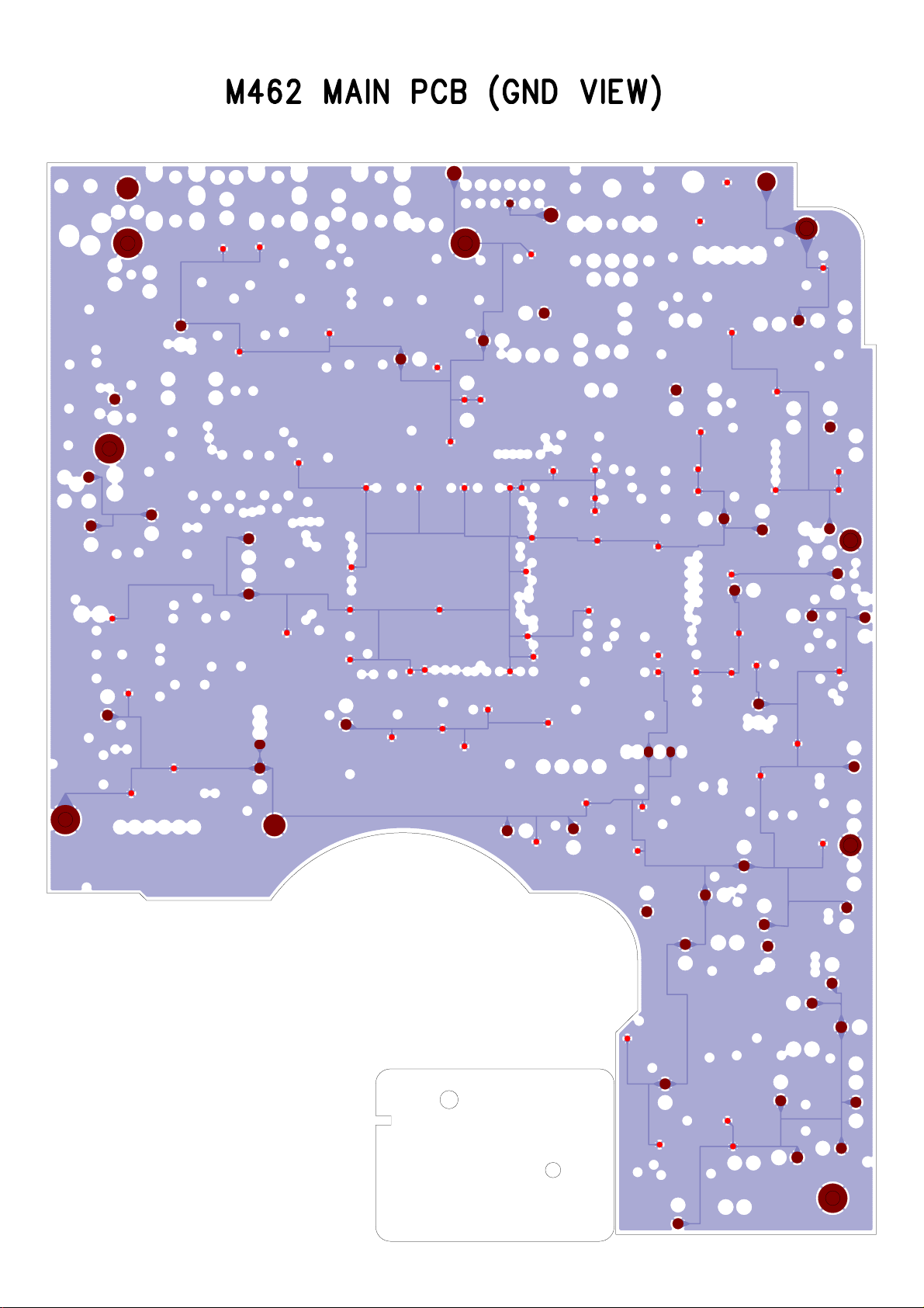


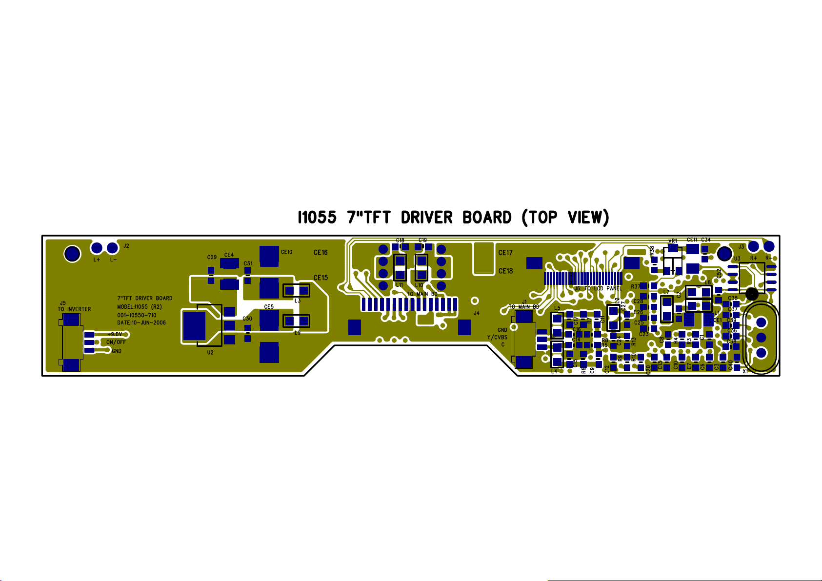


 Loading...