


SPARCstation 5 Service
Manual
Sun Microsystems Computer Company A Sun Microsystems, Inc. Business
901 San Antonio Road Palo Alto, CA 94303-4900 USA 650 960-1300
fax 650 969-9131
Part No.: 801-6396-11
Revision A, August 1994

1994 Sun Microsystems, Inc., 901 San Antonio Road, Palo Alto, California 94303-4900 U.S.A.
All rights reserved.
This product or document is protected by copyright and distributed under licenses restricting its use, copying, distribution, and decompilation. No part of this product or document may be reproduced in any form by any means without prior written authorization of Sun and its licensors, if any.
Portions of this product may be derived from the UNIX® system, licensed from Novell, Inc., and from the Berkeley 4.3 BSD system, licensed from the University of California. UNIX is a registered trademark in the United States and in other countries and is exclusively licensed by X/Open Company Ltd. Third-party software, including font technology in this product, is protected by copyright and licensed from Sun’s suppliers. RESTRICTED RIGHTS: Use, duplication, or disclosure by the U.S. Government is subject to restrictions of FAR 52.227-14(g)(2)(6/87) and FAR 52.227-19(6/87), or DFAR 252.227-7015(b)(6/95) and DFAR 227.7202-3(a).
Sun, Sun Microsystems, the Sun logo, and Solaris are trademarks or registered trademarks of Sun Microsystems, Inc. in the United States and in other countries. All SPARC trademarks are used under license and are trademarks or registered trademarks of SPARC International, Inc. in the United States and in other countries. Products bearing SPARC trademarks are based upon an architecture developed by Sun Microsystems, Inc.
The OPEN LOOK® and Sun™ Graphical User Interfaces were developed by Sun Microsystems, Inc. for its users and licensees. Sun acknowledges the pioneering efforts of Xerox Corporation in researching and developing the concept of visual or graphical user interfaces for the computer industry. Sun holds a nonexclusive license from Xerox to the Xerox Graphical User Interface, which license also covers Sun’s licensees who implement OPEN LOOK GUIs and otherwise comply with Sun’s written license agreements.
THIS PUBLICATION IS PROVIDED “AS IS” WITHOUT WARRANTY OF ANY KIND, EITHER EXPRESS OR IMPLIED, INCLUDING, BUT NOT LIMITED TO, THE IMPLIED WARRANTIES OF MERCHANTABILITY, FITNESS FOR A PARTICULAR PURPOSE, OR NONINFRINGEMENT.
Copyright 1994 Sun Microsystems, Inc., 901 San Antonio Road, Palo Alto, Californie 94303-4900 U.S.A. Tous droits réservés.
Ce produit ou document est protégé par un copyright et distribué avec des licences qui en restreignent l’utilisation, la copie et la décompilation. Aucune partie de ce produit ou de sa documentation associée ne peut être reproduite sous aucune forme, par quelque moyen que ce soit, sans l’autorisation préalable et écrite de Sun et de ses bailleurs de licence, s’il y en a.
Des parties de ce produit pourront être derivées du système UNIX® licencié par Novell, Inc. et du système Berkeley 4.3 BSD licencié par l’Université de Californie. UNIX est une marque enregistrée aux Etats-Unis et dans d’autres pays, et licenciée exclusivement par X/Open Company Ltd. Le logiciel détenu par des tiers, et qui comprend la technologie relative aux polices de caractères, est protégé par un copyright et licencié par des fournisseurs de Sun.
Sun, Sun Microsystems, le logo Sun, et Solaris sont des marques déposées ou enregistrées de Sun Microsystems, Inc. aux Etats-Unis et dans d’autres pays. Toutes les marques SPARC, utilisées sous licence, sont des marques déposées ou enregistrées de SPARC International, Inc. aux Etats-Unis et dans d’autres pays. Les produits portant les marques SPARC sont basés sur une architecture développée par Sun Microsystems, Inc.
Les utilisateurs d’interfaces graphiques OPEN LOOK® et Sun™ ont été développés de Sun Microsystems, Inc. pour ses utilisateurs et licenciés. Sun reconnaît les efforts de pionniers de Xerox Corporation pour la recherche et le développement du concept des interfaces d’utilisation visuelle ou graphique pour l’industrie de l’informatique. Sun détient une licence non exclusive de Xerox sur l’interface d’utilisation graphique, cette licence couvrant aussi les licenciés de Sun qui mettent en place les utilisateurs d’interfaces graphiques OPEN LOOK et qui en outre se conforment aux licences écrites de Sun.
CETTE PUBLICATION EST FOURNIE "EN L’ETAT" SANS GARANTIE D’AUCUNE SORTE, NI EXPRESSE NI IMPLICITE, Y COMPRIS, ET SANS QUE CETTE LISTE NE SOIT LIMITATIVE, DES GARANTIES CONCERNANT LA VALEUR MARCHANDE, L’APTITUDE DES PRODUITS A REPONDRE A UNE UTILISATION PARTICULIERE OU LE FAIT QU’ILS NE SOIENT PAS CONTREFAISANTS DE PRODUITS DE TIERS.
Please
Recycle

Contents
1.Product Description 1-1
1.1Standard Features 1-1
1.1.1 Subassemblies, Boards, and Components 1-2
1.1.2Interior View 1-2
1.1.3 Rear View of SPARCstation 5 System 1-3
1.2Internal Options 1-4
1.3External Options 1-5
2.Troubleshooting Overview 2-1
2.1 |
Factory-Defined Boot Mode |
2-1 |
2.2 |
After Power Is Switched On |
2-4 |
2.3 |
Diagnostic Tools and When to Use Them 2-7 |
|
2.4Power-On Self-Test 2-7
2.5 FORTH-Based PROM Diagnostics 2-8
2.6FORTH Monitor 2-11
2.7 |
SunDiag System Exerciser 2-11 |
2.8SunDiagnostic Executive 2-11
3. Power-On Self-Test (POST) 3-1
3.1 |
Power-On Self-Test (POST) 3-1 |
3.2 |
Normal Mode 3-4 |
Contents iii
3.3 |
Full Diagnostic Mode |
3-4 |
3.4 |
Abbreviated Diagnostic Mode 3-5 |
|
|
3.4.1 Setting Up a tip Connection to Another System 3-5 |
|
3.5 |
Tests the POST Runs |
3-6 |
3.6 |
POST Error Messages |
3-8 |
3.7 |
Status Lights (LEDs) and Indicators 3-8 |
|
4.Troubleshooting Procedures 4-1
4.1 |
No Video Output on the System Monitor 4-2 |
||
4.2 |
Power-On Does Not Succeed 4-2 |
||
|
4.2.1 |
Power Supply Test |
4-3 |
|
4.2.2 |
System Board Test |
4-5 |
4.3 |
Disk Drive Errors 4-6 |
|
|
|
4.3.1 |
Verifying the Built-In SCSI Controller 4-6 |
|
4.4 |
Determining Faulty DSIMM Locations 4-7 |
||
5. Safety and Tools Requirements |
5-1 |
||
5.1Safety Requirements 5-1
5.2Symbols 5-2
5.3System Precautions 5-3
5.4Tools Required 5-4
5.5 |
Electrostatic Discharge (ESD) Precautions 5-4 |
||
6. Power On and Off 6-1 |
|
||
6.1 |
Powering Off the System |
6-1 |
|
|
6.1.1 |
When the System Is Working Normally 6-1 |
|
|
6.1.2 |
When the System Does Not Respond Normally 6-2 |
|
6.2 |
Powering On the System |
6-4 |
|
7.Internal Access 7-1
7.1 Removing the Cover 7-1
iv SPARCstation 5 Service Manual • August 1994
7.2 |
Attaching the Wrist Strap 7-3 |
7.3 |
Replacing the Cover 7-4 |
8.Major Subassemblies 8-1
8.1Power Supply 8-1
8.1.1 |
Removing the Power Supply |
8-1 |
8.1.2 |
Replacing the Power Supply |
8-3 |
8.2Power LED 8-4
8.2.1 |
Removing the Power LED |
8-4 |
8.2.2 |
Replacing the Power LED |
8-5 |
8.3Internal Speaker 8-7
8.3.1 |
Removing the Internal Speaker |
8-7 |
8.3.2 |
Replacing the Internal Speaker |
8-10 |
8.4SCSI Backplane 8-11
8.4.1 |
Removing the SCSI Backplane |
8-11 |
8.4.2 |
Replacing the SCSI Backplane |
8-13 |
9.Storage Devices 9-1
9.1 |
Hard Disk Drive 9-1 |
|
|
|
9.1.1 |
Removing a Hard Disk Drive |
9-2 |
|
9.1.2 |
Replacing a Hard Disk Drive |
9-3 |
9.2CD-ROM Drive 9-5
9.2.1 |
Removing the CD-ROM Drive |
9-5 |
9.2.2 |
Replacing the CD-ROM Drive |
9-6 |
9.3Diskette Drive 9-8
|
9.3.1 |
Removing the Diskette Drive |
9-9 |
|
9.3.2 |
Replacing the Diskette Drive |
9-12 |
9.4 |
Internal SCSI Data Cable 9-15 |
|
|
|
9.4.1 |
Removing the Internal SCSI Cable 9-15 |
|
|
9.4.2 |
Replacing the Internal SCSI Data Cable 9-17 |
|
9.5 |
DC Power Harness 9-20 |
|
|
Contents v
|
9.5.1 |
Removing the DC Power Harness |
9-20 |
||
|
9.5.2 |
Replacing the DC Power Harness |
9-23 |
||
9.6 |
Diskette Data Cable |
9-26 |
|
|
|
|
9.6.1 |
Removing the Diskette Data Cable |
9-26 |
||
|
9.6.2 |
Replacing the Diskette Data Cable |
9-27 |
||
9.7 |
CD-ROM Audio Cable 9-28 |
|
|
||
|
9.7.1 |
Removing the CD-ROM Audio Cable |
9-28 |
||
|
9.7.2 |
Replacing the CD-ROM Audio Cable |
9-29 |
||
10. System Board Overview |
10-1 |
|
|
||
10.1Damage Prevention 10-1
10.2 |
Handling System Boards and Assemblies 10-1 |
|
10.3 |
System Board Layout 10-2 |
|
10.4 |
Replaceable System Board Components |
10-3 |
11. System Board and Component Replacement |
11-1 |
|
11.1SBus Cards 11-1
11.1.1 |
Removing an SBus Card |
11-2 |
|
11.1.2 |
Replacing an SBus Card |
11-5 |
|
11.2 S24 Frame Buffer Card 11-7 |
|
|
|
11.2.1 |
Removing an S24 Frame Buffer Card |
11-8 |
|
11.2.2 |
Replacing an S24 Frame Buffer Card |
11-10 |
|
11.3DSIMMs 11-12
11.3.1 Removing a DSIMM 11-13
11.3.2 Replacing a DSIMM 11-15
11.4System Board 11-17
11.4.1 |
Removing the System Board |
11-17 |
11.4.2 |
Replacing the System Board |
11-19 |
11.4.3 Setting Jumpers 11-21
11.5NVRAM 11-23
11.5.1 Removing the NVRAM Chip 11-23
vi SPARCstation 5 Service Manual • August 1994
|
11.5.2 Replacing the NVRAM Chip |
11-24 |
|||||
12. Illustrated Parts Breakdown |
12-1 |
|
|
|
|||
12.1 |
Illustrations of Selected CRUs |
12-1 |
|
||||
12.2 |
Replacement Parts List |
12-4 |
|
|
|
||
A. System Specifications A-1 |
|
|
|
|
|
||
A.1 |
Physical Specifications |
A-1 |
|
|
|
||
A.2 |
Input Power Requirements |
A-2 |
|
|
|||
A.3 |
Environmental Requirements |
A-2 |
|
||||
B. SPARCstation 5 Input/Output Connectors |
B-1 |
||||||
B.1 |
SCSI Connector (External) |
B-1 |
|
|
|||
B.2 |
Parallel Port Micro-D Connector |
B-2 |
|
||||
B.3 |
Attachment Unit Interface (AUI) Micro-D Connector B-3 |
||||||
B.4 |
Twisted-Pair Ethernet Connector |
B-4 |
|
||||
B.5 |
Serial Connector Ports A and B |
B-5 |
|
||||
B.6 |
Keyboard/Mouse Connector |
B-6 |
|
|
|||
B.7 |
Audio Ports B-6 |
|
|
|
|
|
|
|
B.7.1 |
Headphone Connector |
B-7 |
|
|||
|
B.7.2 |
Audio Line-out Connector |
B-7 |
||||
|
B.7.3 |
Audio Line-in Connector |
B-8 |
|
|||
|
B.7.4 |
Microphone Connector |
B-8 |
|
|||
B.8 |
13W3 Video Connector |
B-8 |
|
|
|
||
C.SCSI Targeting C-1
D.FORTH Diagnostics D-1
D.1 Running the FORTH Diagnostics D-1
D.1.1 |
test <alias name>, test <device path> D-3 |
D.1.2 |
test-all D-4 |
D.1.3 |
watch-clock D-4 |
Contents vii
D.1.4 |
watch-net, watch-aui, watch-tpe, and watch-net-all D-4 |
D.1.5 |
probe-scsi, probe-scsi-all D-7 |
D.1.6 |
module-info D-7 |
D.1.7 |
test-memory D-8 |
D.2 Returning to the Old-Style Sunmon Compatibility Mode Prompt D-8
Glossary Glossary-1
viii SPARCstation 5 Service Manual • August 1994

Figures
FIGURE 1-1 |
Basic SPARCstation 5 System |
1-2 |
|
|
||
FIGURE 1-2 |
Interior View of SPARCstation 5 System |
1-3 |
|
|||
FIGURE 1-3 |
Rear View of SPARCstation 5 System 1-4 |
|
||||
FIGURE 2-1 |
Factory-Defined Boot Sequence—POST Phase Settings and Tests 2-2 |
|||||
FIGURE 2-2 |
Factory-Defined Boot Sequence—OpenBoot PROM Phase Settings and Tests 2-3 |
|||||
FIGURE 3-1 |
Arrangement of Sun Type-5 Keyboard Diagnostic LEDs |
3-2 |
||||
FIGURE 3-2 |
Sun Type-4 Keyboard |
3-2 |
|
|
|
|
FIGURE 3-3 |
Sun Compact 1 Keyboard |
3-3 |
|
|
|
|
FIGURE 3-4 |
SPARCstation System Banner |
3-4 |
|
|
||
FIGURE 3-5 |
Location of System Power LED |
3-8 |
|
|
||
FIGURE 4-1 |
Power Supply Connector |
4-4 |
|
|
|
|
FIGURE 4-2 |
DSIMM Slot Locations |
4-8 |
|
|
|
|
FIGURE 7-1 |
Removing the Rear Panel Cover Screws |
7-2 |
|
|||
FIGURE 7-2 |
Removing the Cover |
7-3 |
|
|
|
|
FIGURE 7-3 |
Grounding the Wrist Strap to the Power Supply 7-4 |
|
||||
FIGURE 7-4 |
Replacing the Cover |
7-5 |
|
|
|
|
FIGURE 7-5 |
Securing the System Unit Cover |
7-6 |
|
|
||
FIGURE 8-1 |
Removing the Power Supply 8-2 |
|
|
|||
FIGURE 8-2 |
Connecting the DC Power Harness to the Power Supply |
8-3 |
||||
Figures ix
FIGURE 8-3
FIGURE 8-4
FIGURE 8-5
FIGURE 8-6
FIGURE 8-7
FIGURE 8-8
FIGURE 9-1
FIGURE 9-2
FIGURE 9-3
FIGURE 9-4
FIGURE 9-5
FIGURE 9-6
FIGURE 9-7
FIGURE 9-8
FIGURE 9-9
FIGURE 9-10
FIGURE 9-11
FIGURE 9-12
FIGURE 9-13
FIGURE 9-14
FIGURE 9-15
FIGURE 9-16
FIGURE 9-17
FIGURE 9-18
FIGURE 9-19
FIGURE 9-20
FIGURE 9-21
FIGURE 9-22
Power LED and In-line Connector 8-5 |
|||
Positioning the LED Cable |
8-6 |
|
|
Removing the Speaker Cover |
8-8 |
||
Removing the Speaker |
8-9 |
|
|
Speaker Connections |
8-10 |
|
|
Removing the SCSI Backplane |
8-12 |
||
Drive Locations 9-2 |
|
|
|
Removing a Hard Disk Drive |
9-3 |
||
Replacing a Disk Drive |
9-5 |
|
|
Removing the CD-ROM Drive |
9-6 |
||
Jumper Settings for SPARCstation 5 CD-ROM Drive 9-7
Replacing the CD-ROM Drive |
9-8 |
|
|
Diskette Drive Location |
9-9 |
|
|
Removing the CD-ROM Filler Panel |
9-10 |
||
Disengaging the Diskette Drive 9-11 |
|||
Removing the Diskette Drive |
9-12 |
|
|
Diskette Drive Switch and Grommets 9-13 |
|||
Replacing the Diskette Drive |
9-14 |
|
|
System Board Cable Connections |
9-16 |
||
Rear Panel Captive Screws |
9-16 |
|
|
Removing the System Board |
9-17 |
|
|
Internal Cable Routing |
9-18 |
|
|
Replacing the System Board |
9-19 |
|
|
Backpanel Captive Screws 9-19 |
|
||
System Board Cable Connections |
9-21 |
||
1 Panel Captive Screws |
9-21 |
|
|
Removing the System Board |
9-22 |
|
|
Internal Cable Routing |
9-23 |
|
|
x SPARCstation 5 Service Manual • August 1994
FIGURE 9-23
FIGURE 9-24
FIGURE 9-25
FIGURE 9-26
FIGURE 9-27
FIGURE 10-1
FIGURE 11-1
FIGURE 11-2
FIGURE 11-3
FIGURE 11-4
FIGURE 11-5
FIGURE 11-6
FIGURE 11-7
FIGURE 11-8
FIGURE 11-9
FIGURE 11-10
FIGURE 11-11
FIGURE 11-12
FIGURE 11-13
FIGURE 11-14
FIGURE 11-15
FIGURE 11-16
FIGURE 11-17
FIGURE 11-18
FIGURE 11-19
FIGURE 11-20
FIGURE 11-21
FIGURE 11-22
Replacing the System Board |
9-24 |
Backpanel Captive Screws |
9-25 |
System Board Cable Routing |
9-27 |
Audio Connector on the CD-ROM Drive 9-28 |
|
CD-ROM Audio Connector on the System Board 9-29
SPARCstation 5 System Board |
10-2 |
|
|
|||
SBus Slot Locations |
11-1 |
|
|
|
|
|
Opening the SBus Card Retainers |
11-2 |
|
||||
Removing the Extractor From the SBus Card |
11-3 |
|||||
Installing the SBus Card Extractor |
11-3 |
|
||||
Removing a Single-Width SBus Card |
11-4 |
|
||||
Removing a Double-Width SBus Card |
11-4 |
|
||||
Inserting the SBus Card 11-6 |
|
|
|
|
||
Closing the SBus Card Retainers |
11-7 |
|
||||
AFX Bus Slot 11-8 |
|
|
|
|
|
|
Opening the Card Retainers |
11-9 |
|
|
|
||
Removing an S24 Frame Buffer Card |
11-10 |
|
||||
Inserting the S24 Frame Buffer Card |
11-11 |
|
||||
Closing the Card Retainers |
11-12 |
|
|
|
||
DSIMM Slot Locations on the System Board |
11-14 |
|||||
Ejecting a DSIMM |
11-14 |
|
|
|
|
|
Orienting a DSIMM |
11-15 |
|
|
|
|
|
Installing a DSIMM |
11-16 |
|
|
|
|
|
System Board Cable Connections |
11-18 |
|
||||
System Board Captive Screws |
11-18 |
|
|
|||
Removing the System Board |
11-19 |
|
|
|||
Installing the System Board |
11-20 |
|
|
|
||
System Board Captive Screws |
11-20 |
|
|
|||
Figures xi
FIGURE 11-23
FIGURE 11-24
FIGURE 12-1
FIGURE 12-2
FIGURE 12-3
FIGURE 12-4
FIGURE B-1
FIGURE B-2
FIGURE B-3
FIGURE B-4
FIGURE B-5
FIGURE B-6
FIGURE B-7
FIGURE B-8
FIGURE B-9
FIGURE B-10
FIGURE B-11
FIGURE B-12
Setting the Serial Port Jumpers |
11-22 |
|||
Locating the NVRAM |
11-23 |
|
|
|
Selected CRUs—System Unit |
12-1 |
|||
Standard External Cables |
12-2 |
|
||
Optional External Cables |
12-3 |
|
||
Microphone and Cable |
12-3 |
|
|
|
External SCSI Connector |
B-1 |
|
||
Parallel Port Micro-D Connector |
B-2 |
|||
Attachment Unit Interface (AUI) Micro-D Connector B-3 |
||||
Twisted-Pair Ethernet Connector |
B-4 |
|||
Serial Connector B-5 |
|
|
|
|
Keyboard/Mouse Connector |
B-6 |
|||
SPARCstation 5 Audio Ports |
B-6 |
|||
Headphone Connector |
B-7 |
|
|
|
Audio Line-out Connector |
B-7 |
|
||
Audio Line-in Connector |
B-8 |
|
|
|
Microphone Connector |
B-8 |
|
|
|
SPARCstation 5 13W3 Video Connector B-9
xii SPARCstation 5 Service Manual • August 1994

Tables
TABLE 1-1
TABLE 1-2
TABLE 2-1
TABLE 2-2
TABLE 2-3
TABLE 2-4
TABLE 3-1
TABLE 4-1
TABLE 4-2
TABLE 4-3
TABLE 4-4
TABLE 5-1
TABLE 12-1
TABLE 12-2
TABLE A-1
TABLE A-2
TABLE A-3
TABLE B-1
TABLE B-2
TABLE B-3
Internal Options 1-4 |
|
|
|
|
|
|
Selected External SCSI Peripheral Options |
1-5 |
|
|
|||
NVRAM Parameters Used During POST and Boot Sequence |
2-5 |
|||||
Summary of Autoboot and Diagnostic Switch Parameter Settings 2-6 |
||||||
Diagnostic Tools |
2-7 |
|
|
|
|
|
Selected FORTH Diagnostic Tests |
2-8 |
|
|
|
||
Interpreting the Keyboard Diagnostic LEDs |
3-3 |
|
|
|||
Troubleshooting Tips |
4-1 |
|
|
|
|
|
Power Supply Connector Pin Assignments |
4-4 |
|
|
|||
Troubleshooting Disk Drive Errors |
4-6 |
|
|
|
||
Physical Memory Address Ranges for Slots 0 Through 7 4-8 |
|
|||||
Safety Precautions |
5-2 |
|
|
|
|
|
Part Number List—Customer Replaceable Units |
12-4 |
|
||||
Part Number List—Miscellaneous Items 12-5 |
|
|
||||
Physical Specifications |
A-1 |
|
|
|
|
|
Input Power Requirements and Power Dissipation |
A-2 |
|
||||
Environmental Requirements A-2 |
|
|
|
|
||
Pinout Signals for External SCSI Connector |
B-1 |
|
|
|||
Pinout for Parallel Port Micro-D Connector |
B-2 |
|
|
|||
Pinout for Attachment Unit Interface (AUI) Micro-D Connector |
B-3 |
|||||
Tables xiii
TABLE B-4 |
Pinout for Twisted-Pair Ethernet Connector |
B-4 |
|
TABLE B-5 |
Pinout for Serial Connector Ports A and B |
B-5 |
|
TABLE B-6 |
Pinout for Keyboard/Mouse Connector B-6 |
|
|
TABLE B-7 |
Signals for the SPARCstation 5 Audio Ports B-7 |
|
|
TABLE B-8 |
13W3 Video Connector Pin Assignments |
B-9 |
|
TABLE C-1 |
SCSI Targeting—Solaris 1.x (SunOS 4.x) Operating Systems |
C-1 |
|
TABLE C-2 |
SCSI Targeting—Solaris 2.x (SunOS 5.x) Operating Systems |
C-2 |
|
xiv SPARCstation 5 Service Manual • August 1994

Preface
This service manual describes how to troubleshoot problems and replace parts in the SPARCstation™ 5 computer system. Technicians, advanced computer system endusers (with experience replacing hardware and troubleshooting), system administrators, or qualified service providers should use this book.
Document Organization
This book is divided into seven parts. A table, at the beginning of each part, lists the chapters, sections, and page numbers.
■Part 1, “System Information,” provides an overview of the SPARCstation 5 standard features, internal options, and external options.
■Part 2, “Troubleshooting,” provides a troubleshooting overview, describes how to run and troubleshoot errors displayed during the Power-On Self-Test (POST), and presents symptoms and corrective actions.
■Part 3, “Preparing for Service,” explains safety requirements, symbols used in this book, tools required, and how to shut down, power off, and power on the system.
■Part 4, “Subassembly Removal and Replacement,” describes how to open and close the system, attach and remove a wrist strap, and remove and replace subassemblies.
■Part 5, “System Board,” provides an overview of the system board, describes how to remove and replace the system board and replaceable parts and components on the system board.
■Part 6, “Illustrated Parts Breakdown,” provides illustrations of the major replaceable parts and lists part numbers.
xv
■Part 7, “Appendixes, Glossary, Index,” provides physical, electrical, and environmental specifications, connector pinouts and signal descriptions, information on SCSI targeting, a glossary of technical terms, and an index.
Related Documentation
The following manuals describe software troubleshooting procedures:
■OpenBoot Command Reference
■SunDiag User’s Guide
■System administration manual for the computer system
■Operating system documentation
Typographic Conventions
The following table describes the type changes and symbols used in this book.
TABLE P-1 Typographic Conventions
Typeface or |
|
|
Symbol |
Meaning |
Example |
AaBbCc123 The names of commands, files, and directories; on-screen computer output
AaBbCc123 What you type, contrasted with on-screen computer output
AaBbCc123 Command-line placeholder: replace with a real name or value
AaBbCc123 Book titles, new words or terms, or words to be emphasized
Edit your .login file. Use ls -a to list all files.
system% You have mail.
system% suPassword:
To delete a file, type rm filename.
Read Chapter 6 in Owner’s Guide. These are called class options. You must be root to do this.
Code samples are included in boxes and may display the following:
xvi SPARCstation 5 Service Manual • August 1994

TABLE P-1 Typographic Conventions
Typeface or |
|
|
Symbol |
Meaning |
Example |
|
|
|
% |
UNIX C shell prompt |
system% |
$ |
UNIX Bourne and Korn shell |
$ |
|
prompt |
|
# |
Superuser prompt, all shells |
# |
|
|
|
Preface xvii
xviii SPARCstation 5 Service Manual • August 1994

C H A P T E R 1
Product Description
This chapter presents a brief overview of the major components of the SPARCstation 5 system. Please acquaint yourself with the overview before servicing and maintaining the hardware for this product.
1.1Standard Features
The SPARCstation 5 system accommodates the following storage devices:
■535-Mbyte single-connector hard disk drive
■1.05-Gbyte single-connector hard disk drive
■Diskette drive
■Internal CD-ROM drive
It also accommodates up to 256 Mbytes of memory using dynamic single in-line memory modules (DSIMMs). The system has four audio ports on the back panel and includes an internal speaker. FIGURE 1-1 shows a typical SPARCstation 5 system.
1-1

FIGURE 1-1 Basic SPARCstation 5 System
1.1.1Subassemblies, Boards, and Components
The SPARCstation 5 system unit accommodates the following subassemblies, boards, and components:
■System board
■DSIMMs (up to 8)
■S24 graphics card
■SBus cards (up to 3)
■Hard disk drives, 3.5-inch, 88.0-mm, single-connector (up to 2)
■CD-ROM drive
■Diskette drive (3.5-inch)
■Power supply (150-watt with 2 fans)
1.1.2Interior View
FIGURE 1-2 shows an interior view of the major subassemblies and the system board for the SPARCstation 5 system.
1-2 SPARCstation 5 Service Manual • August 1994
Diskette drive |
CD-ROM drive |
Hard drives |
(bottom unit) |
(top unit) |
(stacked) |
Power |
|
|
|
|
|
|
|
|
|
|
|
|
|
|
|
|
|
|
DSIMMs |
|
|
|
|
|
|
|
|
|
|
|
|
|
|
|
|
|
|
||
|
|
|
|
|
|
|
|
|
|
|
|
|
|
|
|
|
|
||
|
|
|
|
|
|
|
|
|
|
|
|
|
|
|
|
|
|
||
|
|
|
|
|
|
|
|
|
|
|
|
|
|
|
|
|
|
||
|
|
|
|
|
|
|
|
|
|
|
|
|
|
|
|
|
|
AFX Bus slot |
|
supply |
|
|
|
|
|
|
|
|
|
|
|
|
|
|
|
|
|
|
|
|
|
|
|
|
|
|
|
|
|
|
|
|
|
|
|
|
|
|
SBus slots |
|
|
|
|
|
|
|
|
|
|
|
|
|
|
|
|
|
|
|
|
|
|
|
|
|
|
|
|
|
|
|
|
|
|
|
|
|
|
|
|
|
|
|
|
PROM |
|
|
|
|
|
|
|
|
NVRAM |
||||||
|
|
|
|
|
|
|
|
|
|
|
|
|
|
||||||
FIGURE 1-2 |
Interior View of SPARCstation 5 System |
||||||||||||||||||
1.1.3Rear View of SPARCstation 5 System
FIGURE 1-3 shows the rear view of the system.
Chapter 1 Product Description 1-3

Legend: |
|
|
|
|
1—AC On/Standby switch |
|
7—SCSI |
13—Keyboard |
|
2—AC power outlet |
|
8—Parallel |
14—Audio, headphone |
|
3—Lock block |
|
|
9—AUI Ethernet |
15—Audio, line-out |
4—SBus |
|
|
10—Twisted-pair Ethernet |
16—Audio, line-in |
5—SBus or AFX Bus |
|
11—Serial port B |
17—Audio, microphone |
|
6—AC power receptacle |
|
12—Serial port A |
|
|
1 |
2 |
3 |
4 |
5 |
|
|
|
|
|
|
|
|
|
|
|
|
|
|
|
|
|
|
|
|
|
|
|
|
|
|
|
|
|
|
|
|
|
|
|
|
|
|
|
|
|
|
|
|
|
|
|
|
|
|
|
|
|
|
|
|
|
|
|
|
|
|
|
|
|
|
|
|
|
|
|
|
|
|
|
|
|
|
|
|
|
|
|
|
|
|
|
|
|
|
|
|
|
|
|
|
|
|
|
|
14 |
|
16 |
|
|
|||
|
|
|
|
|
|
|
|
|
|
|
|
|
|
|
|
|
|
|
|
|
|
|||||
6 |
|
7 |
8 9 |
10 |
11 |
12 |
13 |
15 |
|
17 |
||||||||||||||||
FIGURE 1-3 |
Rear View of SPARCstation 5 System |
|
|
|
|
|
|
|
|
|
|
|
|
|||||||||||||
1.2Internal Options
TABLE 1-1 lists the internal options.
TABLE 1-1 Internal Options
Option |
Quantity |
Comments |
|
|
|
S24 card |
1 |
Provides accelerated 24-bit color graphics on |
|
|
the system AFX Bus. |
SBus cards |
Up to 3 |
System board provides up to three SBus slots |
|
|
for additional system functionality. |
Hard disk drives |
1 or 2 |
System supports up to two disk drives of |
|
|
varying capacities. See Chapter 9 for more |
|
|
information. |
|
|
|
1-4 SPARCstation 5 Service Manual • August 1994

TABLE 1-1 Internal Options
Option |
Quantity |
Comments |
|
|
|
CD-ROM drive |
1 |
Internal CD-ROM drive. |
Diskette drive |
1 |
Internal diskette drive for diskette I/O. |
DSIMMs |
Up to 8 |
System supports up to 256 Mbytes of dynamic |
|
|
single in-line memory modules (DSIMMs). |
|
|
|
1.3External Options
TABLE 1-2 lists selected external small computer system interface (SCSI) options.
TABLE 1-2 Selected External SCSI Peripheral Options
Unit |
Description |
|
|
Desktop Backup Pack |
150-Mbyte tape drive or DAT tape drive. |
Desktop Disk Pack |
Disk expansion unit with a variety of SCSI disk drive |
|
capacities. |
Desktop SunCD™ Pack |
Compact CD-ROM disc drive. |
Desktop Storage Module |
1.3-Gbyte disk drive or 5.0-Gbyte tape drive. |
SCSI Expansion Pedestal |
Up to seven SCSI disks, compact CD-ROM drive, tape |
|
drive, other non-disk units. |
Multi-Disk Pack |
Desktop enclosure containing a disk array of SCSI disk |
|
drives. |
20-Gbyte 4-mm Desktop Tape |
Desktop enclosure containing a tape drive with |
Auto-Loader |
multiple magazine cartridges; provides up to 20 Gbytes |
|
of tape backup storage. |
SCSI Expansion Pedestal |
Holds up to eight disk drives and two or three |
|
removable media in the upper tray. Requires a |
|
minimum of two SCSI controllers if all three trays are |
|
used. You cannot have more than seven SCSI devices |
|
on each SCSI bus. |
|
|
Chapter 1 Product Description 1-5
1-6 SPARCstation 5 Service Manual • August 1994

C H A P T E R 2
Troubleshooting Overview
This chapter describes the factory-defined boot sequence. It also describes the different types of SPARCstation 5 diagnostic firmware and software tools that are available to you for troubleshooting; the chapter explains how the tools are related and when to use them.
2.1Factory-Defined Boot Mode
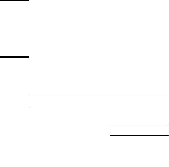
The flowcharts in FIGURE 2-1 and FIGURE 2-2 outline the roles played by various diagnostics during a factory-defined boot operation under the control of the OpenBoot™ PROM (OBP) firmware.
The following sections describe the relationship between the various diagnostic tools, and the role each tool plays during the SPARCstation 5 factory-defined boot sequence. The descriptions in the following sections assume you are using a graphics monitor to view test results.
FIGURE 2-1 (POST phase) and FIGURE 2-2 (OBP phase) graphically depict the flow of OBP processing control, after power is switched on. Each figure depicts the possible paths for processing control, and the switch settings for the factory-defined boot sequence. By examining the two flowcharts you can see where in the processing sequence other diagnostic tests are available or are encountered.
2-1
|
|
|
|
Yes |
Stop |
No |
|
|
Stop-d |
No |
|||||||||||||
Power-on switch |
|
Keyboard |
|
|
key |
|
|
keys |
|
|
|
diag- false (default) |
|||||||||||
|
|
attached |
|
|
pressed? |
|
|
pressed? |
|
|
|
switch? |
|
|
|||||||||
|
|
? |
|
|
|
|
|
|
|
|
|
|
|
|
|
|
|
|
|
|
|
|
|
|
|
|
No |
|
Yes—Skip POST |
|
Yes—Set |
true |
|
||||||||||||||
|
|
|
|
|
|
||||||||||||||||||
|
|
|
|
|
diag-switch? to true |
|
|||||||||||||||||
|
|
|
|
|
|
|
|
|
|
|
|
||||||||||||
|
|
|
|
|
|
|
|
|
|
|
|
|
|
|
|
|
|
|
|
|
|
|
|
|
|
|
|
|
|
|
|
|
|
|
|
|
|
|
|
|
|
Low-level diagnostic: |
|
|
|||
|
|
|
|
|
|
|
|
|
|
|
|
|
|
|
|
|
|
POST phase |
|
|
|||
POST phase |
|
|
|
|
|
|
|
|
Display errors on |
|
|
|
|
|
|
|
|
|
|||||
|
|
|
|
|
|
|
|
|
|
|
|
|
|
|
|
|
|||||||
|
|
|
|
|
|
|
|
|
|
|
|
|
|
|
|
|
|||||||
|
|
|
|
|
|
|
|
|
|
|
|
|
|
|
|
|
|
|
|||||
|
|
|
|
|
|
|
|
|
|
keyboard LEDs |
|
|
|
No POST |
|
||||||||
|
|
|
|
|
|
|
|
|
|
|
and console |
|
|
|
|
||||||||
|
|
|
|
|
|
|
|
|
|
|
|
|
|
|
|
passed |
|
||||||
|
|
|
|
|
|
|
|
|
|
|
|
|
|
|
|
|
|
|
|
|
|||
|
|
|
|
|
|
|
|
|
|
|
|
|
|
|
|
|
|
|
|
Yes |
|
||
|
|
|
|
|
|
|
|
|
|
|
|
|
|
|
|
|
|
|
|
|
|||
|
|
|
|
|
|
|
|
|
|
|
|
|
|
|
|
|
|
|
|
|
|||
|
|
|
|
|
|
|
|
|
|
|
OpenBoot PROM firmware takes control |
||||||||||||
|
|
|
|
|
|
|
|
|
|
|
|
|
|
|
|
|
|
|
|
|
|
|
|
FIGURE 2-1 Factory-Defined Boot Sequence—POST Phase Settings and Tests
If you need to run extended FORTH Diagnostics to take advantage of more extensive tests, see Appendix D.
2-2 SPARCstation 5 Service Manual • August 1994

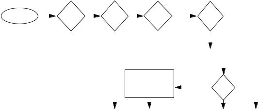
After POST phase, OpenBoot PROM firmware takes control
OpenBoot PROM Phase
System initialization |
|||
Probe memory |
|
||
|
Probe CPU |
|
|
Yes |
Stop-n |
|
|
keys |
|
||
|
pressed? |
|
|
|
|
No |
|
etting nvram defaults |
|
|
|
|
Stop-d |
Yes |
|
|
keys |
||
|
pressed? |
|
|
|
No |
Set diag-switch? |
|
|
|
|
|
true |
use- |
|
|
|
nvramrc? |
|
|
Evaluate the |
|
false |
|
script |
|
|
|
Probe SBus devices and |
|||
interpret their drivers |
|||
Install console |
|
||
System banner |
|||
displayed on screen |
|||
|
Stop-a Yes |
|
|
keys |
|
|
pressed? |
|
|
No |
|
|
false diag- |
true |
|
switch? |
|
Tests |
selftest-#megs |
Tests all memory |
|
|
Press Stop-a |
|
|
to go to ok prompt |
|
mfg- |
true |
|
switch? |
|
|
false |
|
|
auto- |
false |
|
boot? |
|
|
true |
|
|
diag- |
false |
|
|
|
|
switch? |
|
|
true |
|
Booting from diag-device=net |
|
Booting from boot-dev=disk |
|
|
|
|
|
ok prompt |
|
|||||
|
and diag-file |
|
and boot-file |
|
|
|
|
|
|
|
|
|||
|
|
|
|
|
|
|
|
|
|
|
|
|
|
|
|
|
|
|
|
|
|
|
|
||||||
|
|
Press Stop-a to go to ok prompt |
|
|
|
|
|
|||||||
|
|
|
|
|
|
|
||||||||
|
|
|
|
|
|
|
|
|
|
|
|
|
|
|
|
Normal |
|
|
|
Boot <boot-device> |
|
|
On-board |
|
|||||
|
operating system |
|
|
|
<boot-file> |
|
|
diagnostics |
|
|||||
|
|
|
|
|
|
|
|
|
|
|
|
|
|
|
SunDiag System
Exerciser
FIGURE 2-2 Factory-Defined Boot Sequence—OpenBoot PROM Phase Settings and Tests
Chapter 2 Troubleshooting Overview 2-3

2.2After Power Is Switched On
When you turn on the system power, the low-level POST phase is initiated if any of the following circumstances apply:
■diag-switch? NVRAM parameter is set to true.
■Stop-d keys are held down when you turn on the power.
■Keyboard is disconnected, and diag-switch? is set to false.
The low-level POST code, which is stored in the boot PROM, is designed to test the most basic functions of the system hardware. The status of the POST is conveyed by four LEDs on the Sun Type-4, Type-5, and Compact 1 keyboards. The Caps Lock LED blinks to indicate that the tests are in progress. If a failure is detected during low-level POST, one of the other three LEDs will light to indicate the nature of the failure. See Chapter 3 for more information.
Note –You can skip the POST phase by turning on the system while holding down the Stop key.
At the successful completion of the low-level POST phase, the OpenBoot PROM firmware takes control and performs the following initialization sequence:
■Initialize system
■Probe memory, then CPU
■Evaluate Script (if use-nvramrc? is set to true)
■Probe SBus devices and interpret their drivers
■Install the console (see FIGURE 2-2)
After initialization, a system banner appears on the screen, and the high-level testing begins. When the high-level tests are finished, the system checks parameters stored in the NVRAM to determine the next step. Depending on the following parameter settings, the system will:
■Boot the operating system from a specified location, if auto-boot? is set to true
■Suppress the boot sequence and enter the FORTH Monitor (ok prompt), if autoboot? is set to false
■Continually cycle through the OpenBoot PROM sequence, if mfg-switch? is set to true
Note –If you are in the Sunmon compatibility mode (prompt is >) type n to return to the OBP monitor (prompt is ok).
2-4 SPARCstation 5 Service Manual • August 1994

TABLE 2-1TABLE 2-1 contains a list of NVRAM parameters and explains their effect on the power-up sequence. For more detailed information about NVRAM parameters, see the OpenBoot Command Summary.
Note –At any point during the high-level OBP execution, you can abort the OBP sequence and access the FORTH Monitor by pressing the Stop and “a” keys simultaneously.
TABLE 2-1 NVRAM Parameters Used During POST and Boot Sequence
NVRAM Parameter |
Description |
|
|
selftest-#megs |
This parameter determines how many megabytes of |
Default = 1 |
memory to test during high-level OBP testing if diag- |
|
switch? is concurrently set to false. The minimum is |
|
zero; the maximum is the amount actually installed in the |
|
system. The default is a 1-megabyte test. |
diag-switch? |
When set to true, this parameter forces the system to test |
Default = false |
automatically all available memory. It also enables |
|
diagnostic message output to serial port A. If a properly |
|
configured terminal or “tip window” is connected, |
|
diagnostic progress can be monitored through this port. |
|
When auto-boot? is set to true and diag-switch? is set |
|
to false, diag-switch? forces the system to boot from |
|
the device and file specified in boot-dev and boot-file. |
auto-boot? |
If auto-boot? is set to true and diag-switch? is set to |
Default = true |
true, the system boots the operating system from the |
|
device and file specified in the diag-device and diag- |
|
file NVRAM parameter fields. When set to false, this |
|
will suppress the boot sequence. The system halts with the |
|
ok prompt. |
|
|
At the FORTH Monitor prompt, you can direct the system to boot the operating system from a location that you specify, or you can execute a variety of additional FORTH-based tests. See the OpenBoot Command Reference for a complete description of the FORTH Monitor.
Chapter 2 Troubleshooting Overview 2-5

If the auto-boot? parameter is set to true (the default), the system boots a standalone program. To determine which program and device to boot from, the system checks the diag-switch? NVRAM parameter. TABLE 2-2 summarizes the effect of the auto-boot? and diag-switch? parameters.
TABLE 2-2 Summary of Autoboot and Diagnostic Switch Parameter1 Settings
auto-boot? |
diag-switch? |
Result |
|
|
|
false |
false or true |
> or ok prompt |
true |
false |
Boot operating system from |
|
|
device alias “disk” or |
|
|
“net” for SPARCstation 5 |
|
|
system |
true |
true |
Boot operating system from |
|
|
device alias “net” |
|
|
|
1.The boot parameters represented here are default settings. The defaults may be changed by following the procedures listed in the OpenBoot Command Summary.
Once the operating system is running, you can invoke the SunDiag™ System Exerciser if further diagnostic testing is warranted. Refer to Section 2.7, “SunDiag System Exerciser,” for additional information.
Another standalone diagnostic program you can run is the SunDiagnostic Executive. Refer to Section 2.8, “SunDiagnostic Executive,” for further information.
To boot user-specified programs, such as the SunDiagnostic Executive, you must be at the > prompt or ok prompt. See Appendix D for a detailed procedure on how to access the > or the ok prompt.
2-6 SPARCstation 5 Service Manual • August 1994
 Loading...