


Theater Grand Processor

User's Manual
Safety Instructions
1. Read Instructions -– All the safety and operation
instructions should be read before the Sunfire Component
is operated.
2. Retain Instructions — The safety and operating
instructions should be kept for future reference.
3. Heed Warnings — All warnings on the Component and
in these operating instructions should be followed.
10. Cleaning — The Component should be cleaned only
as recommended in this manual.
11. Non-use Periods—The power cord of the Component
should be unplugged from the outlet when unused for a
long period of time.
12. Object and Liquid Entry — Care should be taken so
that objects do not fall into and liquids are not spilled into
the inside of the Component.
4. Follow Instructions — All operating and other instructions should be followed.
5. Water and Moisture — The Component should not be
used near water - for example, near a bathtub, washbowl,
kitchen sink, laundry tub, in a wet basement, or near a
swimming pool, etc.
6. Ventilation — The Component should be situated so
that its location or position does not interfere with its
proper ventilation. For example, the Component should
not be situated on a bed, sofa, rug, or similar surface that
may block any ventilation openings; or placed in a built-in
installation such as a bookcase or cabinet that may
impede the flow of air through ventilation openings.
7. Heat — The Component should be situated away from
heat sources such as radiators, or other devices which
produce heat.
8. Power Sources — The Component should be connected
to a power supply only of the type described in these operation instructions or as marked on the Component.
9. Power Cord Protection — Power-supply cords should be
routed so that they are not likely to be walked upon or
pinched by items placed upon or against them, paying
particular attention to cords at plugs, convenience receptacles, and the point where they exit the Component.
13. Damage Requiring Service — The Component should
be serviced only by qualified service personnel when:
A. The power-supply cord or the plug has been damaged; or
B. Objects have fallen, or liquid has spilled into the
Component; or
C. The Component has been exposed to rain; or
D. The Component does not appear to operate normally
or exhibits a marked change in performance; or
E. The Component has been dropped, or its cabinet damaged.
14. Servicing — The user should not attempt to service
the Component beyond those means described in this
operating manual. All other servicing should be referred to
qualified service personnel.
2
Safety Instructions
User's Manual
15. To prevent electric shock, do not use this polarized
plug with an extension cord, receptacle or other outlet
unless the blades can be fully inserted to prevent blade
exposure.
Pour préevenir les chocs électriques ne pas utiliser cette
fiche polariseé avec un prolongateur, un prise de courant
ou une autre sortie de courant, sauf si les lames peuvent
être insérées à fond sans laisser aucune pariie à
découvert.
16. Grounding or Polarization — Precautions should be
taken so that the grounding or polarization means of the
Component is not defeated.
WARNING – TO REDUCE THE RISK OF FIRE OR ELECTRIC SHOCK,
DO NOT EXPOSE THIS APPLIANCE TO RAIN OR MOISTURE.
CAUTION: TO PREVENT ELECTRIC SHOCK, MATCH WIDE BLADE
OF PLUG TO WIDE SLOT, FULLY INSERT.
ATTENTION: POUR
ÉVITER LES CHOCS ÉLECTRIQUES, INTRO-
DUIRE LA LAME LA PLUS LARGE DE LA FICHE DANS LA BORNE
CORRESPONDANTE DE LA PRISE ET POUSSER JUSQU’AU FOND.
This apparatus does not exceed the Class A/Class B
(whichever is applicable) limits for radio noise emissions
from digital apparatus as set out in the radio interference
regulations of the Canadian Department of Communications.
ATTENTION — Le présent appareil numérique n'émet pas
de bruits radioélectriques dépassant las limites
applicables aux appareils numériques de class A/de class
B (selon le cas) prescrites dans le règlement sur le
brouillage radioélectrique édicté par les ministere des
communications du Canada.
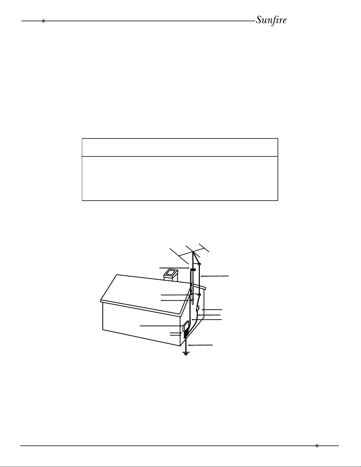
EXAMPLE OF ANTENNA GROUNDING ACCORDING TO NATIONAL
ELECTRICAL CODE INSTRUCTIONS CONTAINED IN ARTICLE
810—“RADIO AND TELEVISION EQUIPMENT”
GROUND CLAMP
ANTENNA
LEAD IN WIRE
GROUND CLAMPS
ANTENNA DISCHARGE UNIT
(NEC SECTION 810-20)
GROUNDING
SERVICE
ENTRANCE
EQUIPMENT
GROUND CLAMPS
CONDUCTORS
(NEC SECTION 810-21)
POWER SERVICE GROUNDING
ELECTRODE SYSTEM
(NEC ART 250, PART H)
NEC NATIONAL ELECTRICAL CODE.
NOTE TO CATV INSTALLER
This reminder is to call the CATV system installer's attention to Article 820-40 of the NEC that provides guidelines for proper grounding and in particular, specifies that the cable ground shall be connected to the grounding
system of the building as close to the point of cable entry as practical.
OUTSIDE ANTENNA GROUNDING
If an outside antenna is connected to the receiver, be sure the antenna system is grounded so as to provide
some protection against voltage surges and built-up static charges. Article 810 of the National Electrical Code,
ANSI/NFPA 70, provides information with regard to proper grounding of the lead-in wire to an antenna-discharge
unit, connection to grounding electrodes, and requirements for the grounding electrode. See Figure above.
Safety Instructions
3
User's Manual
Contents
Safety Instructions..................................................................................... 2-3
Introduction .................................................................................................. 5
Features ....................................................................................................... 6
Unpacking .................................................................................................... 6
Overview ...................................................................................................... 7
Front Panel Features ................................................................................ 8-9
Rear Panel Features ............................................................................. 10-11
Installation .................................................................................................. 12
System Configurations ............................................................................... 13
DVD: analog audio and composite video ................................... 13
DVD: digital and component video............................................. 14
LD: external RF demodulator and S-video.............................. 15
VCR: analog audio and composite video ................................... 16
CD: analog audio and antenna connections............................ 17
Turntable: analog audio and ground connections ............................. 18
Tape Deck: analog audio input and output connections ...................... 19
Processor: analog connections .......................................................... 20
Amplifier: unbalanced RCA connections .......................................... 21
Amplifier: balanced XLR connections............................................... 22
Bass Management ..................................................................................... 23
Speaker Placement ............................................................................... 24-25
Remote Control .....................................................................................26-29
Calibration ............................................................................................. 30-31
Delay Adjustments ..................................................................................... 32
The Surround Modes ................................................................................. 33
Dolby Digital and DTS ........................................................................... 34
Using the Tuner.......................................................................................... 35
Recording ................................................................................................... 36
Holographic Image ..................................................................................... 37
RS-232 Port ............................................................................................... 38
Troubleshooting Guide .......................................................................... 39-41
Specifications ............................................................................................. 42
Limited Warranty ........................................................................................ 43
Service Assistance ..................................................................................... 43
To find out more about this and
other Sunfire products, please
visit our website:
www.sunfire.com
4
Contents
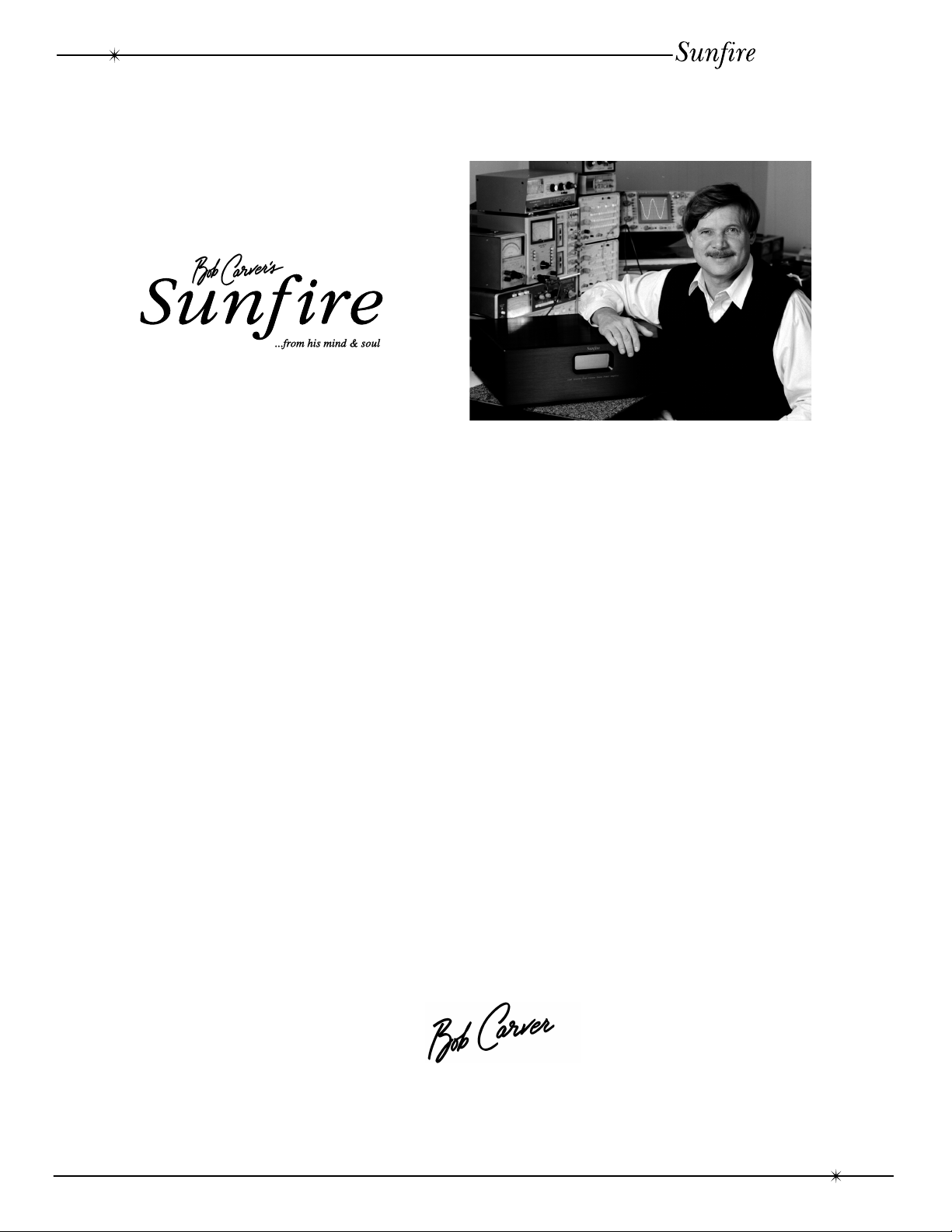
Introduction
Bob Carver, Amplifier Designer, Physicist
Dear Friend,
Thank you for purchasing my Sunfire Theater Grand Processor. I hope that you enjoy it and
the music it makes as much as I have enjoyed creating it for you.
User's Manual
The Sunfire Theater Grand Processor is unlike any home theater product on the market. For
one thing, we have taken special pains to make it as easy to use as possible. As a result, you do
not have to read a manual the size of a large book to figure how to listen to your favorite videotape, DVD or to bring in your favorite FM station. Instead, we’ve designed it to virtually do the
thinking for you.
When you use the “Full Automatic Operation” feature, the correct settings are made by its
sophisticated microprocessors. So, when you turn on your video component, the processor will
choose the proper input for you. All you have to do is adjust the volume the way you want, then
sit back and enjoy. The same holds true if you wish to listen to a CD, watch a DVD and more.
We’ve also made the Theater Grand Processor highly flexible so you can easily adjust it to suit
your taste.
As with our entire line of Sunfire products, the Theater Grand Processor is brimming with
exclusive, high-performance technology that will help you get the highest level of enjoyment from
your home theater system. These include:
• High quality digital signal processors that support sampling rates up to 48kHz.
• FM/AM tuner with 40 station presets
• Holographic Imaging, which gives a greatly enhanced soundstage.
• Automatic 5.1 channel DSP mode selection.
The Theater Grand Processor lets you run all of your audio and video components from a
single easy-to-use control center. So you can experience the extraordinary, dynamic, full-range,
multidimensional, wall-to-wall theater sound.
Introduction
5

User's Manual
Unpacking
Your Theater Grand Processor should
reach you in perfect condition. If you do notice
any shipping damage, please contact your
Sunfire Dealer immediately.
Gently lift out the unit and remove all the
packing material and accessories. It is
important to save all the packing materials
and the box in case your Theater Grand
Processor ever needs to be moved or shipped
for repair.
Make sure that you keep your sales
receipt. It is the only way to establish the
duration of your Limited Warranty and it may
come in useful for insurance purposes.
Please make a note of your serial number
located on the rear panel:
Serial Number:
Purchased at:
Date:
• RS-232 computer control port
• Video screen control port
• Supports all digital sampling rates to
48kHz
• 20-bit Crystal Semiconductor
Digital to Analog converters
• Four microprocessors and two DSP
processors
• DSP “simulated” surround modesfor
two channel sources
• Holographic Imaging for main
channels
• AM/FM tuner with 40 presets
• Gold plated input and output jacks
• Balanced XLR outputs
• Unbalanced RCA outputs
• Three unbalanced subwoofer outputs
Features
• Fully automatic signal-sensing audio
and video input selection
• Dolby Digital, Dolby Pro Logic and
DTS decoding modes
• Five audio/video inputs
• Four audio-only inputs
• One external processor loop
• MM Phono input for records
• Two component video inputs
• Five composite video inputs
• Two S-video inputs
• Two optical digital audio inputs
• Three coaxial digital audio inputs
• Tone controls
• One balanced subwoofer output
• Seven-axis outputs for side speakers
• IEC removable power cord
• Steel chassis with thick milled
aluminum faceplate
• Designed and built in the USA
Remote Features
• Large, ultra-clear, LCD touch panel
display
• Illuminated display
• Learns commands from your other
remote controls
• Macro feature lets you program a
sequence of control steps
• Eight different display views
• Backup battery prevents memory loss
when changing batteries
6
Unpacking and Features
RESET
SURROUND
V.AU X
DAT/TAPE VCR1
+
-
PHONO
TV
VCR CD LD
AMP
TAPE
TUNER
SEL1 SEL2
TUNER CD
LD DBS/BS
DSP
DELETE
DELETE ERROR OK LEARN BAT LOW
LEARN MACRO
VOLUME
CHANNEL
POWER
AMP
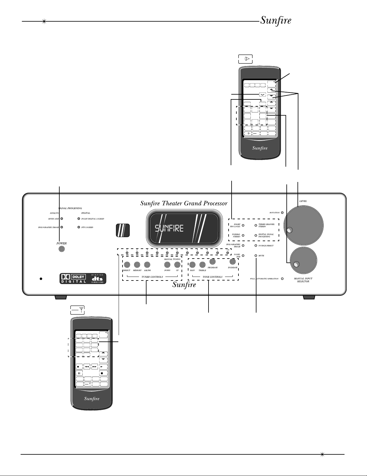
Overview
User's Manual
Most features of the Theater Grand
Processor can be operated by the remote
control’s AMP section. The Tuner station
presets are in the remote’s TAPE/TUNER
section.
For the best home theater performance,
you must first follow the calibration and delay
adjustment procedures.
In stereo use, the calibration can be used
to adjust the balance of the left and right
speakers and to adjust the subwoofer level.
Power
on/off
Mute
Selecting a
surround mode
DSP
Selecting an
input
Power
on/off
Volume
adjustment
TAPE
TUNER
Tuner
controls
Tone
Mute
controls
DELETE ERROR OK LEARN BAT LOW
RESET
DELETE
123
456
789
10 0
REC PLAY
TV
AMP
LEARN MACRO
VCR CD LD
TAPE
SEL1 SEL2
TUNER
POWER
CHANNEL
STOP
Tuner
Presets
Calibration Procedure: Page 30-31
Delay Adjustment: Page 32
Remote Control: Page 26-29
Surround Modes: Page 33-34
Overview
7
User's Manual
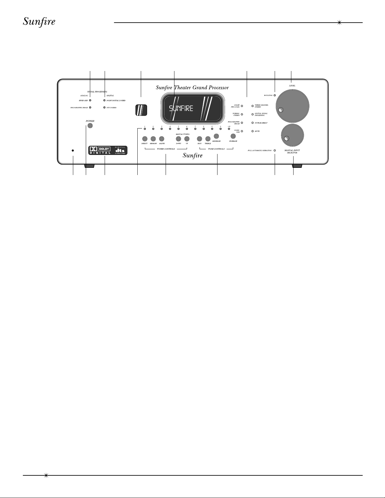
Front Panel Features
12 3 4 5 6 7
910 11 12 13 1415
8
1. Analog Signal Processing
SEVEN AXIS
This light is always on. It indicates that
the Theater Grand Processor is
capable of delivering seven channels of
surround sound. (There are two extra
outputs for side channels).
HOLOGRAPHIC IMAGE
This light is on when the Holographic
Image circuit is engaged.
2. Digital Signal Processing
DOLBY DIGITAL LOCKED
This light is on when a Dolby Digital
signal is being decoded.
DTS LOCKED
This light is on when a DTS signal is
being decoded.
3. Remote Receiver Window
This window should be clean and free
from obstruction for the remote control to
work correctly.
4. Processor Display Window
This display shows which input is selected,
the tuner frequency, volume level and other
useful features during normal use and calibration.
5. Mode Buttons
DOLBY PRO LOGIC
This activates the Dolby Pro Logic
processing, which operates with
surround encoded source material.
NORMAL STEREO
This is the standard two channel stereo
mode.
HOLOGRAPHIC IMAGE
This circuit adds a three dimensional
effect, especially to stereo listening.
PANEL DIM
The front panel lights have three levels:
bright, medium, or low.
THREE CHANNEL STEREO
This mode adds a center channel to the
left and right front channels.
DIGITAL SIGNAL PROCESSING
This adds Jazz, Stadium or Cathedral
ambience to stereo sources.
SOURCE DIRECT
This allows you to bypass the
processor’s tone control settings.
MUTE
This turns off the sound. Press it again
to return to the previous volume level.
8
Front Panel Features

User's Manual
6. Rotation
This light flickers when the volume LEVEL
or the INPUT SELECTOR is being rotated.
7. Level
Rotate this manual control clockwise to
increase the volume. The dB level will appear
in the front panel display. Note that the control
does not rotate when the remote is used.
8. Reset
This is used to Reset the microprocessor
and clear all surround and preset settings. In
normal use, you will not use this feature. See
the Troubleshooting section for details.
9. Power
This turns the Theater Grand Processor on
or off. It is a non-latching momentary button.
10. Illuminated Logo Panel
11. Tuner Presets
13. Tone
To change the Tone, first press BASS or
TREBLE and then press INCREASE or
DECREASE to suit your taste. The display will
show the change in dB level for reference.
Press BASS or TREBLE again to return to
the normal display. The levels are retained.
14. Full Automatic Operation
When this is engaged, the Theater Grand
Processor will automatically switch to the next
input which starts to play. For example, if you
turn on and press Play on your CD player, the
Theater Grand Processor will switch to CD.
When you turn on and press Play on your
VCR, it will select the VCR1 input.
If the Theater Grand Processor is turned
off while the Auto mode is engaged, it will turn
on and select an input whenever an input
becomes active. For example, if you turn on
your CD player and press Play, the Theater
Grand will turn on and select the CD input.
1-10
Selects your favorite stations, previously stored as presets.
+10
Selects presets above 10. Pressing this
a second time accesses station presets
above 20, a third time above 30, the
fourth time to select 40.
12. Tuner Controls
DIRECT
Used to enter a station’s frequency
directly using the 0 - 9 keys.
MEM
Stores the current tuned station into
preset memory.
AM/FM
Selects the AM or FM band.
UP/DOWN
Switch to stations above or below the
frequency of the current station.
Note: We recommend that you turn off
this feature if you are selecting the inputs
manually, or recording.
15. Manual Input Selector
Rotate this to cycle through the different
inputs. The selected input appears in the display.
CD
VAUX1
VCR1
LD/DVD
DBS/BS
PHONO
TUNER
DAT/TAPE
Note: After you have selected an input,
you should check that the Theater Grand
Processor is set to the desired surround
mode (or the stereo mode).
Front Panel Features
9
User's Manual
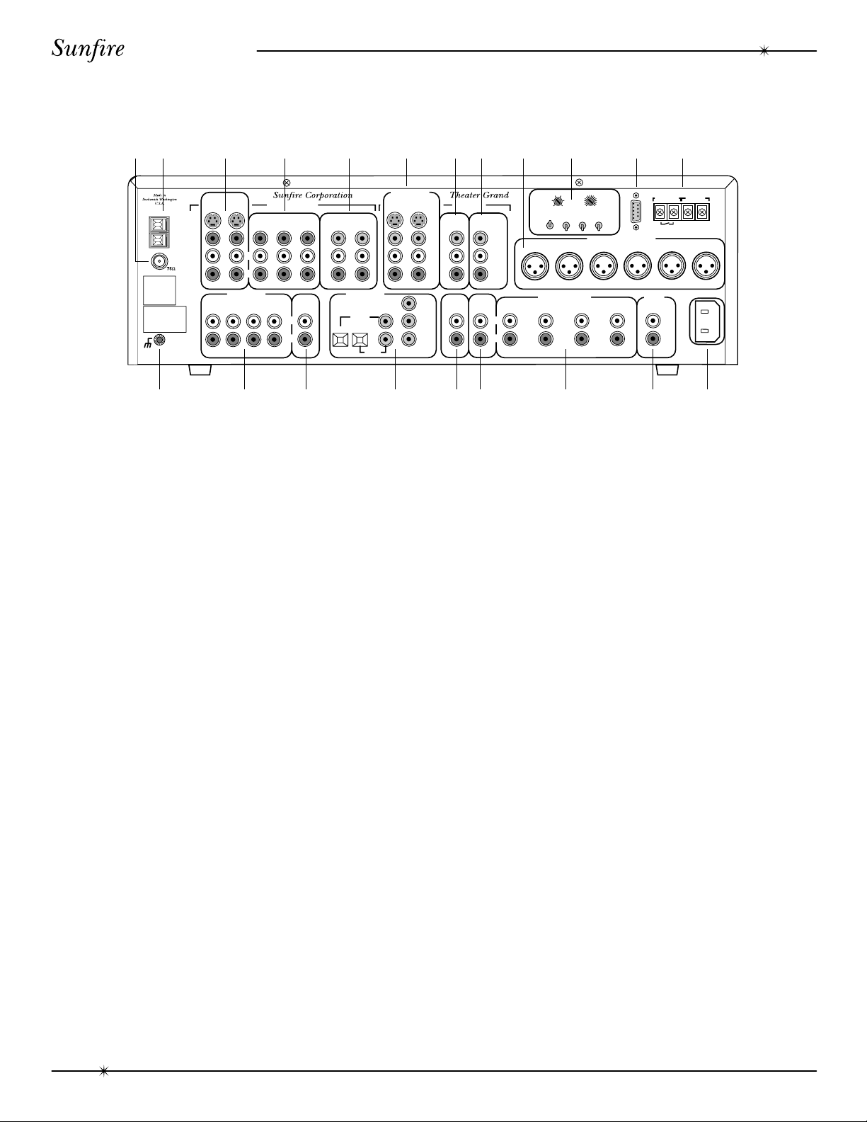
Rear Panel Features
12 3 4 5 6 78 9 10 11 12
R
U
S
O
R
A
U
L
Y
E
D
N
N
E
T
05m
IN
G
E
L
L
A
N
D
D
R
Y
E
D
A
L
510
m
s
015
s
U
S
B
S
R
R
U
O
D
U
N
R
C
N
E
E
T
O
F
F
O
F
F
O
F
F
O
N
O
N
O
N
R
E
T
C
N
E
D
U
S
T
IO
O
U
U
P
T
C
N
R
E
E
T
B
U
1
S
R
-2
2
3
S
A
U
A
N
D
IO
O
B
U
E
A
L
IG
R
R
F
U
D
P
C
T
T
F
E
L
T
H
R
O
N
U
R
U
S
O
D
N
T
S
U
2
S
B
B
U
3
S
V
12
O
F
E
ID
C
U
N
IO
V
T
N
A
R
L
Y
E
D
C
E
O
L
S
M
IL
W
H
N
E
C
A
IV
E
T
S
T
H
IG
R
T
R
O
U
R
U
S
D
N
N
E
V
E
A
IS
X
S
ID
E
S
L
R
V
0
A
2
1
z
H
0
6
N
O
M
A
IN
E
.40
M
A
0
P
E
M
IN
O
M
A
N
IT
O
R
U
O
P
T
S
T
D
/D
V
D
L
B
/B
S
D
S
A
V
O
ID
S
M
G
N
D
M
A
N
IC
E
L
A
L
O
B
O
"PR
D
O
U
A
R
T
D
B
L
A
CO
U
P
N
U
©
992
1
B
A
L
O
R
IG
H
M
A
N
R
F
O
M
IN
C
. U
O
HE
T
IS
S
U
D
IT
IG
R
T
A
D
E
H
A
T
C
O
Y
P
T
S
Y
S
R
S
E
E
A
S
N
IG
G
R
O
U
N
E
O
C
M
O
P
IT
S
E
O
ID
E
V
T
F
E
L
U
IO
A
D
F
M
R
IG
H
T
A
D
U
U
F
NS
R
-L
B
L
E
O
N
B
R
S
T
U
R
E
D
A
E
TE
R
E
R
L
IO
A
C
U
T
N
R
D
D
E
R
U
E
B
L
Y
O
O
M
D
E
FR
A
O
T
R
. "D
IE
S
O
B
L
",
Y
H
N
E
D
O
T
G
IC
' A
M
Y
B
R
S
-D
O
E
E
A
L
M
A
R
S
F
K
O
O
B
D
L
Y
.
S
IE
R
T
O
A
R
L
IA
T
N
E
FID
O
R
K
S.
E
W
ISH
L
D
Y
O
LB
D
97
-19
A
C
O
T
, IN
IE
L
. A
S
L
R
E
S
R
V
E
R
D
E
.
A
F
T
C
R
U
E
D
N
U
D
R
IC
E
E
L
N
E
S
D
D
IG
IT
D
A
T
H
L
A
E
O
. 5,4
A
. N
T
.S
. P
-W
R
D
ID
O
L
W
N
A
D
N
P
E
IN
G
D
U
R
O
U
R
S
L
M
A
K
R
S
O
Y
S
TE
R
S
IG
H
1
IG
D
T
96
9
C
. A
M
S, IN
E
V
.
D
D
C
E
R
T
E
S
T
Y
S
M
S
,
N
1,9
5
A
2
D
4
A
S
T
T
EN
E P
S
T
D
. "
", "D
S
T
R
E
N
D
", A
T
F
E
L
IT
AL
DIG
F
C
.
, IN
M
S
E
T
L
H
IT
A
A
R
E
T
H
IG
S
T
R
LL
R
IG
H
T
A
D
U
IO
V
O
ID
E
IN
U
P
S
T
U
2
A
X
V
1
A
X
V
U
C
V
R
L
R
U
S
IO
T
IN
A
D
U
P
H
P
O
O
N
E
A
P
/T
T
A
R
A
E
T
N
L
X
E
O
O
R
S
C
R
P
S
E
IN
A
T
E
P
L
T
O
N
C
M
O
E
P
N
D
L
/D
B
/B
S
D
S
Y
B
R
Y
Y
IG
IT
A
D
IN
B
/B
D
S
R
U
D
V
R
E
E
IT
O
E
H
S
U
A
U
L
IO
D
S
T
U
P
S
D
L
D
/D
V
U
IO
V
A
O
ID
D
E
O
U
U
P
T
S
T
S
C
O
M
P
O
S
I
T
E
L
R
R
B
O
H
T
C
V
R
C
D
/
D
T
A
E
P
A
T
R
C
E
O
R
D
C
O
M
P
O
N
N
E
T
T
O
U
T
O
U
M
A
IN
V
I
D
Y
B
E
O
R
Y
Y
M
L
R
C
O
O
M
S
P
IT
E
O
E
ID
V
T
F
E
L
T
H
IG
R
C
V
R
O
IT
O
N
R
E
P
A
T
N
L
R
A
E
T
X
E
O
U
T
O
O
R
S
C
R
P
S
E
F
O
T
U
M
L
R
C
M
A
A
L
R
S
M
A
T
F
E
L
R
F
O
T
N
M
A
IN
R
A
E
R
O
T
R
N
O
U
R
U
S
R
A
IN
S
L
R
181716151413 19 20 21
D
.
C
IG
T
R
–+
Y
IF
T
F
M
IA
P
L
S
B
U
S
W
O
R
O
E
F
C
L
E
R
S
1. FM Antenna Connection
The supplied FM antenna fits over the
inner pin of this “F-type” push-on connector.
Other antennas can be fitted if you have a
suitable adaptor.
2. AM Antenna Connection
This is a spring-loaded connection for the
AM loop antenna. Other antennas can be
fitted, including larger diameter loop designs.
3. DBS/BS and LD/DVD Inputs
These audio, composite-video and S-video
inputs connect to the outputs of your DBS/BS or
LD/DVD. When these inputs are selected, the
audio will be heard in your system and the video
will be seen on the TV screen.
4. VCR, VAUX1 and VAUX2 Inputs
These audio and composite-video inputs
connect to the outputs of your VCR machines.
If the VCR input is selected, the audio will be
heard in your system and the video will be seen
on the TV screen.
Note: There is no VAUX2 input selector on
the front panel or remote. If VAUX1 is selected,
the Processor will automatically select either
VAUX1 or VAUX2, whichever one is playing. If
both VAUX1 and VAUX2 are connected, make
sure that only one machine is playing at a time,
otherwise the wrong one may be selected.
5. Component Video Inputs
These component-video inputs connect to
the outputs of your DBS/BS or LD/DVD.
When these inputs are selected, the Processor will automatically route the video signals
going into these jacks to the component video
output (see #7).
6. Main Monitor Outputs
These audio, composite-video and S-video
outputs connect to the corresponding audio
and video inputs of your TV Monitor.
7. Component Video Outputs
These connect to the component video
inputs of your TV monitor. The Processor will
switch the component video signals from any
video equipment connected in #5.
8. VCR Record Outputs
These connect to the inputs of your VCR
to allow recording of the selected input.
9. Balanced XLR Audio Outputs
These connect to the balanced XLR
inputs of your amplifier. If your amplifier has a
choice of inputs, we recommend using the
XLR type for better noise rejection.
10
Rear Panel Features

User's Manual
10. Surround Setup Controls
MAIN: If your front speakers are capable
of good bass performance, set this to
LARGE.
CENTER: If you have a center speaker,
set this to ON.
SURROUND: If you have a pair of sur-
round speakers, set this to ON.
SUB: If you have a Subwoofer, set this
to ON.
CENTER DELAY: This adjusts the time
delay of the center speaker.
SURROUND DELAY: This adjusts the time
delay of the surround speakers.
11. RS-232 Jack
This allows the Processor to be operated by
computer software control. It connects to the
serial jack of a home computer or controller.
12. Video Screen Trigger
15. External Processor Input
This connects to the output of an analog
external processor (see #18).
16. Digital Inputs
These inputs connect to the digital
outputs of your audio/video components. The
DBS/BS and LD/DVD inputs have two options, optical or coaxial. The CD, VCR and
DAT/TAPE digital inputs are coaxial.
Whenever one of these inputs is selected
from the front panel or remote, the Theater
Grand Processor will automatically select the
digital input if there is a signal present,
otherwise it will select the corresponding
analog input.
17. Tape Audio Output
This connects to the input of a Tape Deck
and allows recording of whichever input is
selected.
18. External Processor Output
These are used in custom installations to
trigger video screen deployment. When a
video component is selected, the video
screen will come down after a short delay.
13. Chassis Ground Screw
This is used for the ground connection
wire of a turntable.
14. Audio Inputs
These audio inputs connect to the outputs
of your CD, DAT/TAPE, PHONO and TAPE.
Any standard audio component can be
connected to CD, DAT/TAPE or TAPE, but
only a turntable (Moving Magnet) can be
connected to the PHONO input.
Note: There is no TAPE input selector on
the front panel or the remote control. If you
select DAT/TAPE, the Processor will automatically select either the DAT/TAPE or TAPE
input, whichever is playing. If you have both
DAT/TAPE and TAPE connected, make sure
that only one is playing at a time.
This connects to the input of an analog
external processor. This can then be selected
by holding down the PANEL DIM button until
the message ADPT ON appears in the
display. The two channel analog signal will
then pass through your external processor
and back in through the inputs (see #15).
19. Unbalanced Audio Outputs
These line-level RCA outputs connect to
the inputs of your amplifier and powered
subwoofer(s).
20. Seven-Axis Outputs
These outputs provide two side channels
to complement the left, center, right and
surround channels.
21. IEC Linecord Socket
The Theater Grand Processor comes with
a detachable Linecord which connects here.
Rear Panel Features
11

User's Manual
Installation
Observe the following precautions when
choosing a location for your Theater Grand
Processor:
• Protect it from prolonged exposure to
direct sunlight and other direct
sources of heat, such as heating
vents and radiators.
• Do not expose the unit to rain or
moisture. If fluid or a foreign object
should enter the unit, immediately turn
off the power and contact your Sunfire
Dealer.
• Avoid excessive exposure to
extreme cold or dust.
• Do not place heavy objects on top of
the unit.
AC Power Considerations
Ensure that the unit is plugged into an
outlet capable of supplying the correct voltage
specified for your model.
Care
If you need to clean the front surface, first
turn off the power and then use a slightly
dampened cloth, rubbing with the grain. Be
careful not to scratch the display window.
Connection Tips
Before setting up your new system,
please consider the following :
• Always make sure that your components are all turned OFF before
making or changing any connections.
• Whenever possible, keep the power
cords away from the signal cables
or speaker wires to prevent any hum
or interference being heard in the
speakers.
• Choose reliable hookup cables, also
called patch cords or RCA cables. They
should be fully shielded and as short as
possible for the job.
• Some patch cords can be a very tight
fit and there is usually a preferred
method of getting them off, some have
to be removed with a twisting action.
Be gentle or you may damage the
jacks of the amplifier or your other
components.
• Some special patch cords can only be
hooked up in one direction, these are
usually marked with arrows.
• It is usual for the right patch cord plugs
to be red and the left connections to be
white, grey or black. Video connections
are usually yellow.
Video Connections
The Theater Grand Processor has three
types of video connections: composite video,
S-video, and component video. There are no
internal connections between these three
different types; if you put a composite video
signal in, you will only get composite video out.
Choose component or S-video if your video
system supports it, this will give better picture
quality than composite video.
When an audio/video component is
selected, the audio will play in your system
and the video is switched to a video input of
your TV monitor. This is useful if you have
more than one video source, as the Theater
Grand Processor can do the video switching
for you. If you just have one video source, you
can connect it’s video directly to the TV.
If you want the audio and video of your
TV, cable box or any other component to play
through your system, you can connect it’s
outputs to the VAUX1 or VAUX2 inputs. There
is only one VAUX input selector but the
Theater Grand Processor will automatically
select the one which is playing. You must be
sure that only the desired component is
playing. This is also true for the DAT/TAPE
and TAPE inputs, there is only one input
selector: DAT/TAPE.
12
Installation
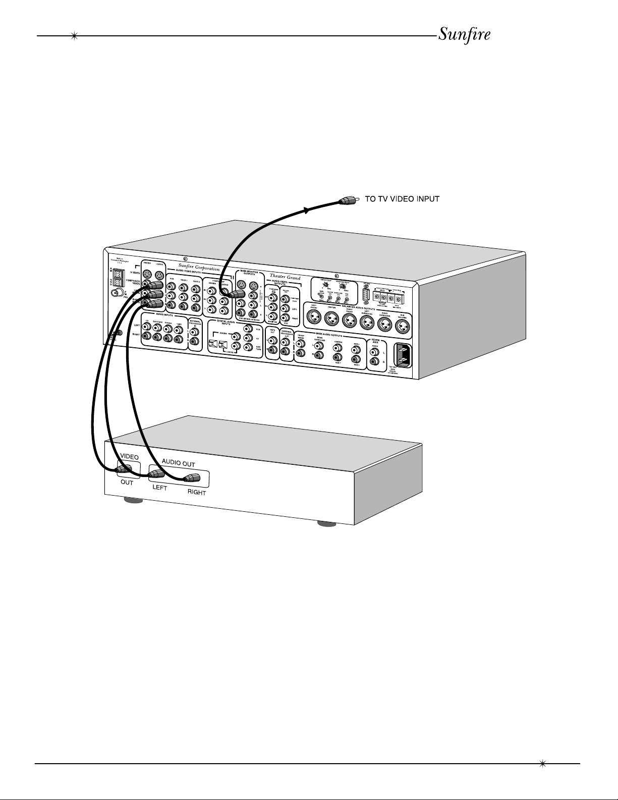
System Configurations
The following pages show some typical
connections that you might make in your installation. They show how the inputs and outputs of
the Theater Grand Processor are connected to
various audio and video components.
User's Manual
When the DVD input is selected on the
front panel or the remote control, the DVD’s
audio will play in your system and the video is
sent to the TV.
As with all the video connections that
follow, you must make sure that your TV
monitor is set to look at it’s correct video input
or you will not see the picture.
DVD Connections-analog audio and composite video
System Configurations
13
User's Manual
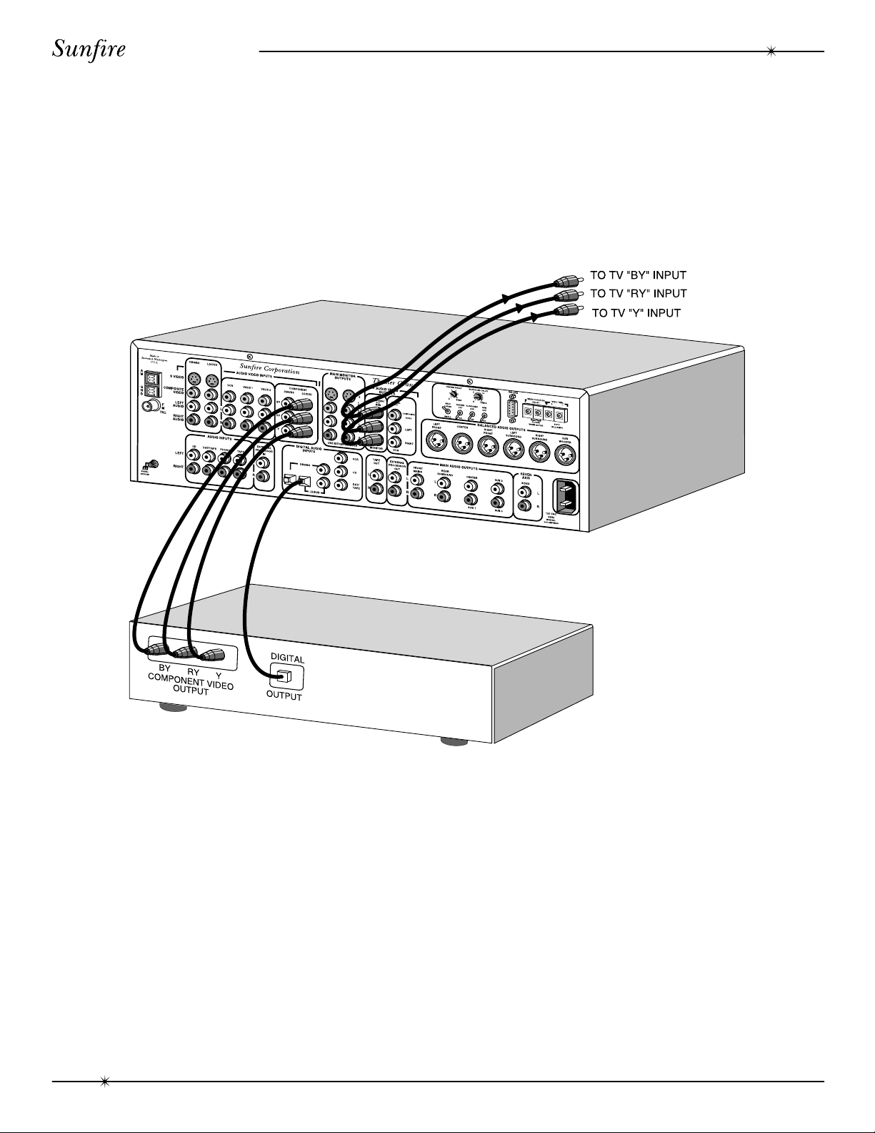
14
If your DVD and TV Monitor both have
component-video, they can be connected as
shown, giving a superior picture.
The digital output from the DVD is connected to the digital inputs of the Theater
Grand Processor, this is the only way it can
receive and decode Dolby Digital or DTS
signals. If you have a choice, use the optical
connection.
DVD Connections-digital audio and component video
System Configurations
 Loading...